

Page 1

Digital Video Recorder
Hardware Technical Reference
Revision 1.1
October 2008
Fast Forward Video
18200-B West McDurmott
Irvine, CA, 92614
USA
Fax: (949) 852-1226
Phone: (949) 852-8404
Page 2

Page 3

CONTENTS
Q HD DVR
CIRCUIT BOARD
Contents
.......................................................................................1
OVERVIEW................................................................................................1
CONFIGURATION.....................................................................................1
ARCHITECTURE.......................................................................................2
HARDWARE BLOCK DIAGRAM .................................................................................................3
SPECIFICATIONS.....................................................................................4
JUMPER AND CONNECTOR LOCATIONS....................................................................................6
CONNECTOR PIN-OUTS..........................................................................6
AUDIO MONITOR OUTPUT.......................................................................................................6
RS-232 – FFV FRONT PANEL PORT J6..................................................................................6
AES3 AND LTC J4 ................................................................................................................7
RS-422 - USER COMMUNICATION J5 - STANDARD...................................................................7
RS-232 – USER COMMUNICATION J5 - ALTERNATE.................................................................7
SATA DATA J21....................................................................................................................8
POWER J23...........................................................................................................................8
JUMPER BLOCK RST, FIRMWARE UPDATE...............................................................................8
APPENDIX.................................................................................................9
MECHANICAL DIMENSIONS......................................................................................................9
ELEVATION............................................................................................................................9
REVISION HISTORY...............................................................................................................10
Q HD DVR Hardware Technical Reference - Rev. 1.1
i
Page 4

Page 5

OVERVIEW
Q HD DVR
CIRCUIT BOARD
Overview
The Q HD is a board level high definition digital video recorder based on J2K compression. With
its broadcast level image quality and near lossless J2K compression, it is ideal for high definition
recording applications that demand only the very best image quality including: high end
surveillance, law enforcement, military and medical.
Q HD is designed with the same cutting-edge digital video recorder technology used in the
Omega HD. It provides outstanding image quality at 1080i, 720p and 480i, records at data rates
up to 100Mbits/s, offers 4:2:2 sampling and a full 10 bit quantization.
High definition recordings are full resolution - 1920 x 1080 (1080i) or 1280 x 720 (720p),
regardless of the compression level used.
With HD-SDI and SD-SDI I/O capabilities the Q HD also features RS-422 control using Sony,
Odetics and FFV serial protocol and an extensive menu of control and configuration options. Q
HD is versatile enough to satisfy a variety of demanding DVR applications.
Configuration
Prior to use, set the configuration to verify operation as expected. Specific settings that should be
checked:
Resolution: 1080i, 720p or 480i; and frame rate: 59.94, and 50.
Disk Format: MOE (Fast Forward Proprietary) or FAT32
File Format: MOE (Fast Forward Proprietary) or QuickTime
Following any change in the Disk or File formats:
“Delete All Video” to prepare the disk for recording.
Other settings as shown in the Serial Control Protocol Document, Section 3.1. The
document, serialxx.pdf, is available from the Technical Support page of www.ffv.com.
Q HD DVR Hardware Technical Reference - Rev. 1.1
1
Page 6

Page 7

ARCHITECTURE
Q HD DVR
CIRCUIT BOARD
Architecture
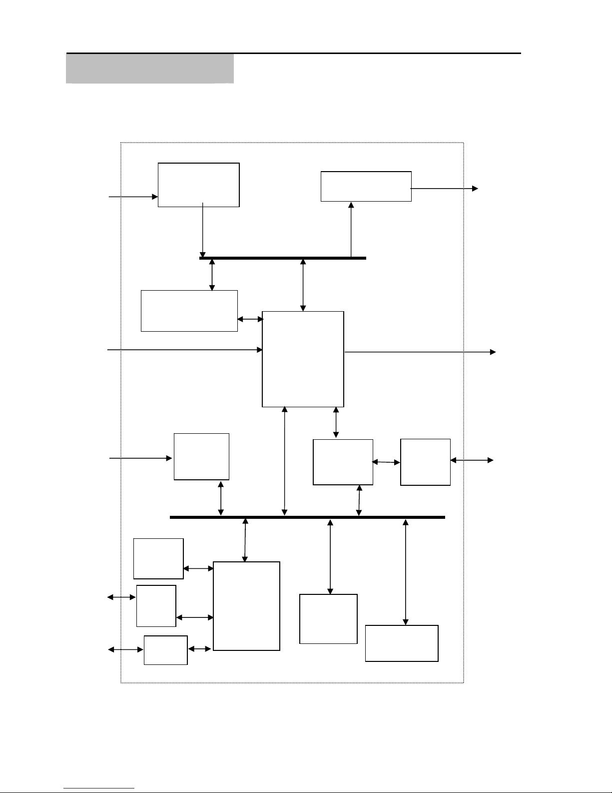
The Q HD DVR’s primary design goal was to maintain video quality at a level suitable for use in
professional video applications. Since image quality is of utmost importance, JPEG2000
compression is used to provide the highest picture quality.
To support a sustained data rate at this level, the designers of the Q HD DVR included a SATA
hard disk controller on the circuit board.
The design includes an on-board ARM processor to oversee the hardware and to provide a
control interface through the serial ports.
All of the Q HD DVR’s subsystems share thirty-two (32) megabytes of dynamic random access
memory. This memory is based on a true multi-port architecture that allows direct access by the
JPEG codec, the disk controller, and the local ARM processor. Direct access to this memory
permits each of the subsystems to perform to their maximum potential without concern for DMA
contention.
Following is a block diagram of the Q HD DVR.
Q HD DVR Hardware Technical Reference - Rev. 1.1
2
Page 8
SPECIFICATIONS
A
/
C
Q HD DVR
CIRCUIT BOARD
HARDWARE BLOCK DIAGRAM
HD-SDI
Video /
Embedded
Audio In
AES Audio
In
LTC In / Out
Video
Equalizer /
De-Serializer
Digital
Video
Bus
JP2K
Compression
Encoder/Decoder
LTC
Codec
32 MB
DRAM, DMA
Subsystem,
and AES
Encoder/
Decoder
IDE Hard
Controller
Video Serializer
Driver
Disk
PATA –
SATA
Bridge
HD-SDI
Video /
Embedded
udio Out
AES Audio
Out
SATA
In / Out
Local
Bus
Real
Time
lock
RS
232
Port
RS232
Port
Q HD DVR Hardware Technical Reference - Rev. 1.1
Micro-
processor
32 MB
Private
SDRAM
16 MB Flash
EPROM
3
Page 9

SPECIFICATIONS
Q HD DVR
CIRCUIT BOARD
Specifications
VIDEO INPUT
Digital Input: Multi-Rate SD/HD–SDI
Standards: SMPTE 274M (1080i)
SMPTE 296M (720p)
SMPTE 347M (NTSC & PAL)
Supported Resolutions: 1080i/29.97
(1920 x 1080I/59.94/2:1 Interlace)
720p/59.94
(1280 x 720/59.94/Progressive)
NTSC (720 x 486/59.94/2:1 Interlace)
PAL (720 x 576/50/2:1 Interlace)
Connections: BNC 75 Ohms
AUDIO INPUT / OUTPUT
Digital Input / Output: 8 Channels embedded HD-SDI
4 Channels embedded SD-SDI
Connections: BNC 75 Ohms
AUDIO SPECIFICATIONS
Resolution: 24 bits
Audio Channels: HD Embedded: 8 in, 8 out
SD Embedded: 4 in, 4 out
4 Channel AES/EBU
these replace embedded channels.
Sampling Rate: 48 KHz
COMMUNICATIONS INTERFACE
RS-422 Interface: 38,400 baud
Protocols: Sony Remote-1 (9-Pin)
Odetics
Fast Forward Native
Firmware update: 57,600 baud, 8 data bits, No parity, 1 stop bit.
DISK CONTROLLER
Protocol: SATA I/II
Maximum Data Rate: 60 Mbit/sec Single Drive
Maximum Hard Drives: 1
Supported Hard Drives: Hitachi, Western Digital, Seagate
Q HD DVR Hardware Technical Reference - Rev. 1.1
4
Page 10

SPECIFICATIONS
Q HD DVR
CIRCUIT BOARD
TIME CODE
SMPTE / EBU Longitudinal (LTC)
VIDEO COMPRESSION
Method: Motion JPEG 2000
Maximum Bit Rate: HD: 100 Mbit / Sec.
SD: 50 Mbit / Sec.
WARRANTY
GENERAL
Physical Dimensions: 4.5” W x 7.0” L x .75” D – D depends on config.
Power Consumption: 10.8 watts not including storage device(s).
Input Voltages: + 3.3 and +5V DC
I Year
Specifications subject to change without notice
Q HD DVR Hardware Technical Reference - Rev. 1.1
5
Page 11
CONNECTORS
JUMPER AND
CONNECTOR
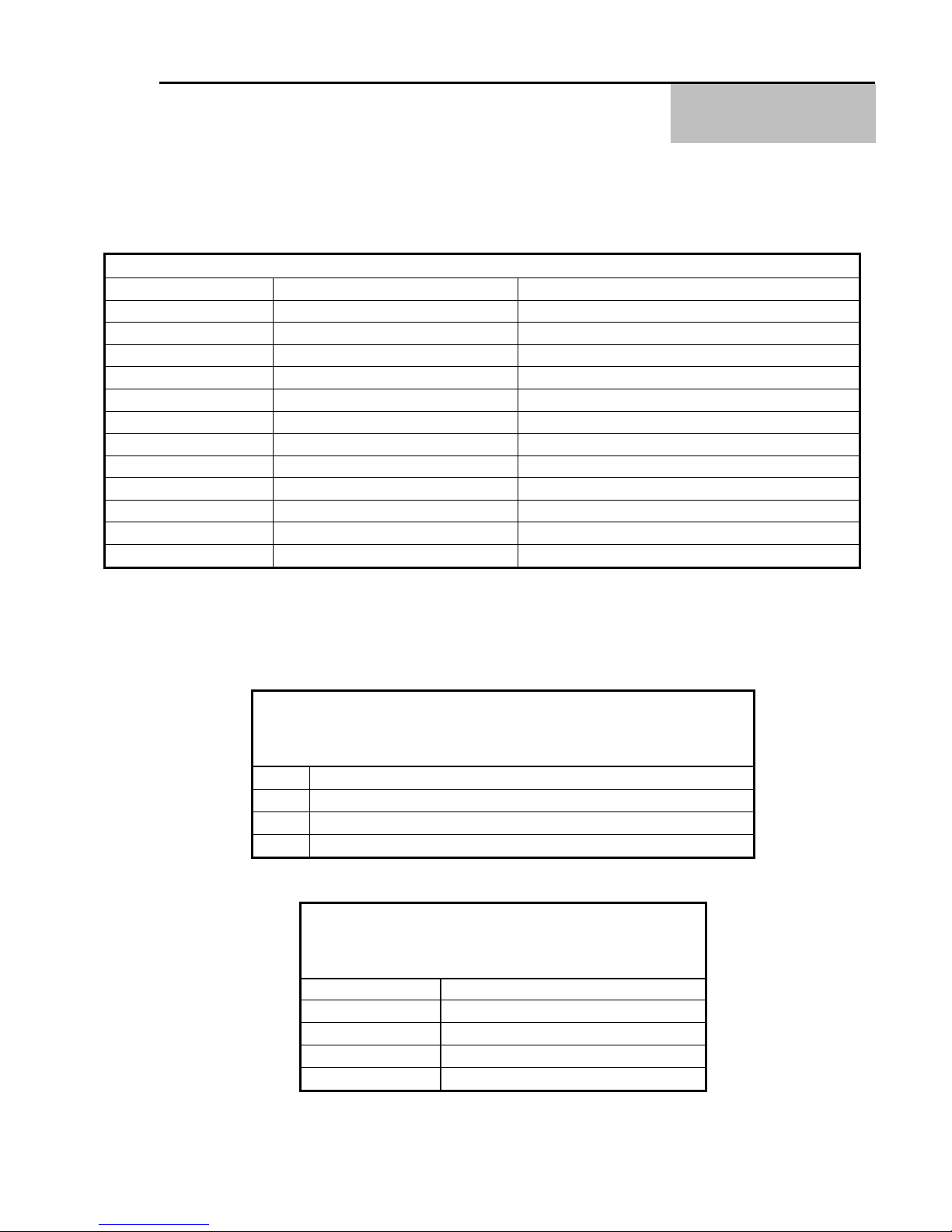
JUMPER AND CONNECTOR LOCATIONS
LEGEND
REF # FUNCTIONAL DESCRIPTION MFR. P/N OR DESCRIPTION
J1 AUDIO MONITOR OUTPUT 3 pin, .1” spacing
J4 AES3 and LTC In / Out 26 pin, 2 row, .1”spacing
J5 RS-422 PORT/ RS-232 OPT. 10 pin, 2 row, .1” spacing
J6 RS-232 Front Panel Port 10 pin, 2 row, .1” spacing
J13 SDI Input BNC – Not Stuffed
J14 SDI Input SMB
J19 SDI OUT BNC – Not Stuffed
J20 SDI OUT SMB
J21 SATA DATA STD. SATA DATA
J23 POWER IN 10 pin, .1” spacing, shrouded
RST RESET STD. 2 PIN IDE, .100 SPACING
FIRMWARE UPDATE FORCE LOAD FIRMWARE STD. 2 PIN IDE, .100 SPACING
LOCATIONS
Pin
1
2
3
Connector Pin-Outs
AUDIO MONITOR OUTPUT
J1
Output
Left Headphone
Right Headphone
Ground
RS-232 – FFV FRONT PANEL PORT
J6
Pin Function
2 DTR
3 Receive Data (RX)
5 Transmit Data (TX)
9 Ground
Q HD DVR Hardware Technical Reference - Rev. 1.1
6
Page 12
CONNECTOR PIN-OUTS
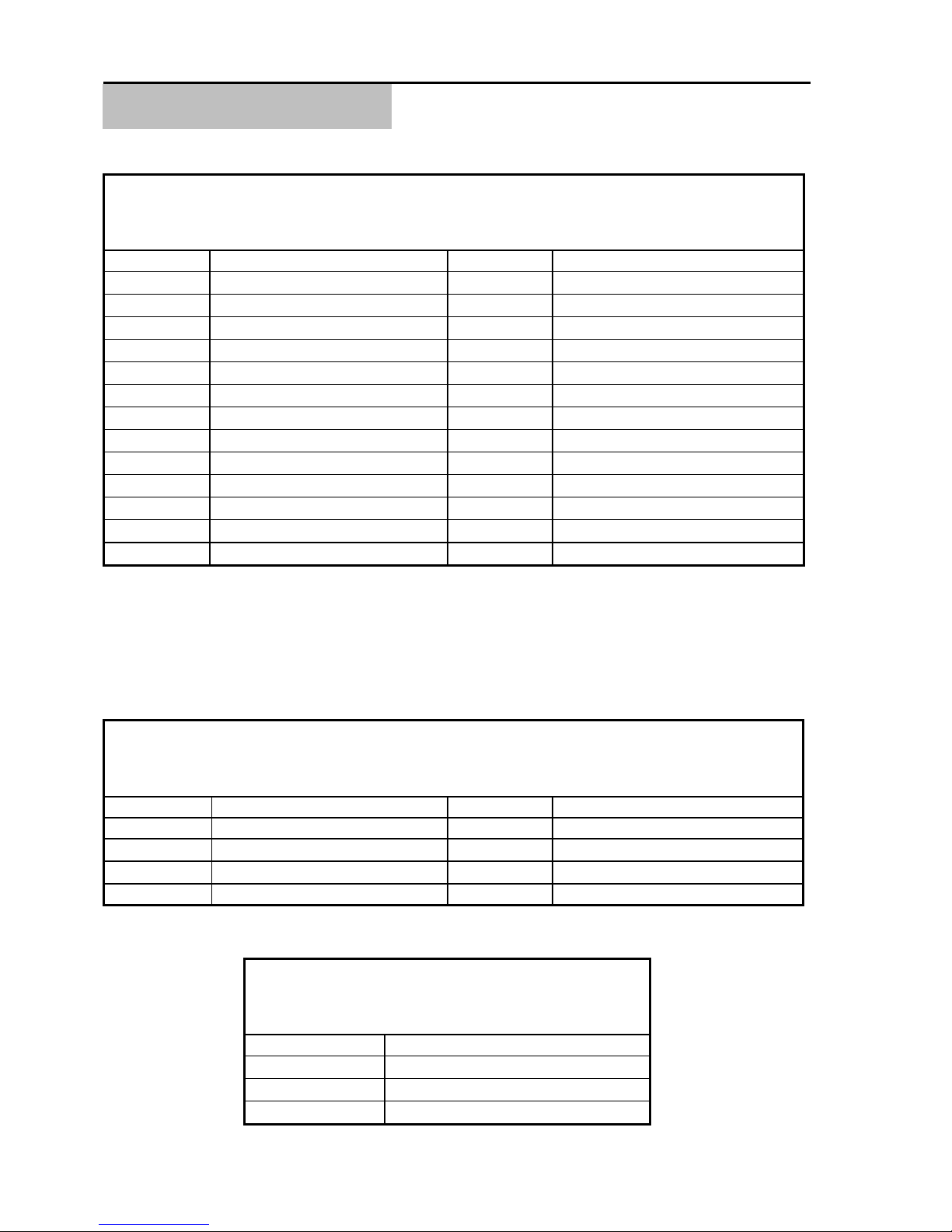
AES3 AND LTC
J4
AES3 AND LTC
J4
Pin Function Pin Function
1 No Connect 2 Ground
3 No Connect 4 Ground
5 No Connect 6 Ground
7 No Connect 8 Ground
9 3 / 4 AES3 IN- 10 3 / 4 AES3 IN+
11 1 / 2 AES3 IN- 12 1 / 2 AES3 IN+
13 1 / 2 AES3 OUT- 14 1 / 2 AES3 OUT+
15 3 / 4 AES3 OUT- 16 3 / 4 AES3 OUT+
17 LTCI- 18 Ground
19 LTCI+ 20 Ground
21 LTCLIK – Sync Clock In* 22 Ground
23 LTCOUT 24 Ground
25 No Connect 26 Ground
Incoming LTC data is loaded into the receive buffer following the receipt of a valid LTC SYNC pattern.
* SMPTE SYNC Sources - A time code generator must have a SYNC input from a stable source in
order to position the LTC code properly on an audio track of video tape or film. Two SYNC sources, click
input, and free running, are available. If some external SYNC source is available it can be input on the
CLICK input. Otherwise, a free running SMPTE SYNC is generated from the oscillator at the selected
frame rate.
RS-422 - USER COMMUNICATION
J5 - STANDARD
Pin Function Pin Function
1 GROUND 2 GROUND
3
5
7 GROUND 8 GROUND
Transmit Data (-)
Receive Data (+)
RS-232 – USER COMMUNICATION
J5 - ALTERNATE
Pin Function
3 Transmit Data (TX)
5 Receive Data (RX)
9 Ground
Q HD DVR Hardware Technical Reference - Rev. 1.1
4
6
Transmit Data (+)
Receive Data (-)
7
Page 13
CONNECTOR PIN-OUTS
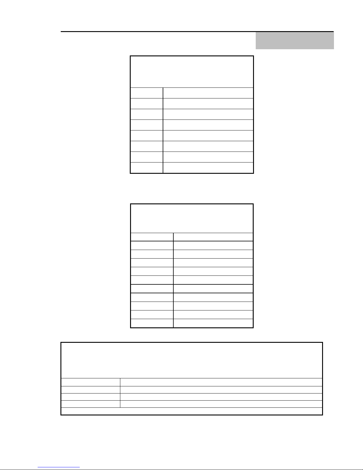
SATA DATA
Pin Function
1 Ground
2 SATA Tx+
3 SATA Tx4 Ground
5 SATA Rx6 SATA Rx+
7 Ground
SATA DATA
J21
J21
POWER
J23
Pin Function
1 +12V – Not Needed
2 +5 Volt / 2 Amp
3 +5 Volt / 2 Amp
4 +3.3 Volt / 0.33Amp
5 +3.3 Volt / 0.33Amp
6 Ground
7 Ground
8 Ground
9 Ground
10 No Connect
JUMPER BLOCK
RST, FIRMWARE UPDATE
Jumper Function
RST Hardware Reset or Initialize DVR
Firmware Update Force DVR into firmware update when shorted during power on.
Default Update Protocol - 57600 baud, 8 data, No parity, 1 stop bits
Q HD DVR Hardware Technical Reference - Rev. 1.1
8
Page 14

Page 15
APPENDIX
MECHANICAL
DIMENSIONS
Appendix
MECHANICAL DIMENSIONS
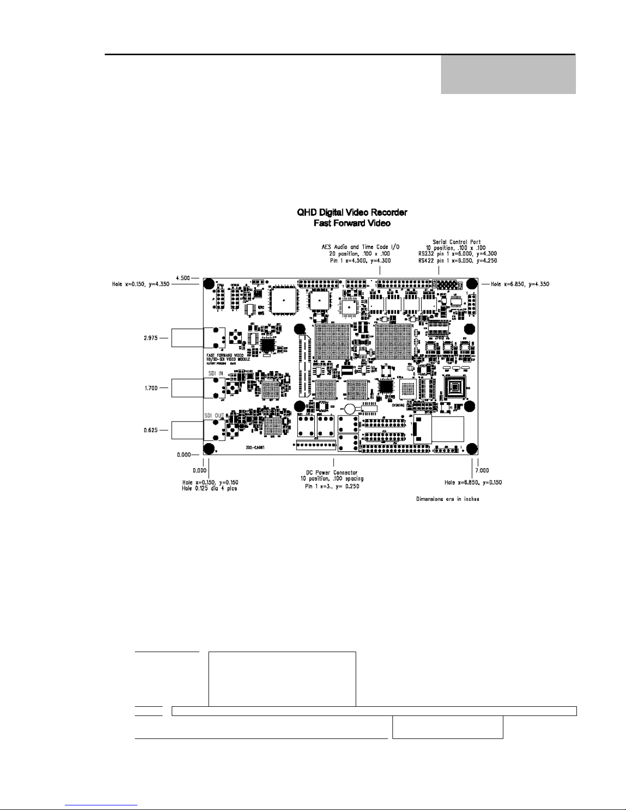
The following dimensional information represents the Rev. C board.
The following dimensions assume all connectors are used. Non-use of connectors will vary total
installed height. Wiring loop may effect space requirements.
.500"
.063"
.100"
Q HD DVR Hardware Technical Reference - Rev. 1.1
ELEVATION
Max Connector Height
Board Thickness
Max Component Height
9
Page 16

Page 17

REVISION HISTORY
Rev. 1.0 – Aug. 28, 2008 - New Release
Rev. 1.1 – Oct. 23, 2008 – Add details for LTC Sync Clock Input.
APPENDIX
REVISION HISTORY
Q HD DVR Hardware Technical Reference - Rev. 1.1
10
 Loading...