

Page 1

FF-8070
Operations Manual
Digital Voice Recorder
Revised December 14, 2002
Copyright © FF Systems 2001, 2002, All Rights Reserved
Page 2

P.O. Box 5533
FFSYSTEMS
Round Rock, TX 78683
512-365-1120 (voice)
" AFFORDABLE REPEATER CONTROL SOLUTIONS "
FF-8070 Digital Voice Recorder V2.24
Table of Contents
Warranty............................................................................................ 1
Introduction........................................................................................ 2
Operation Overview............................................................................... 2
Installation.......................................................................................... 3
DVR Functions .................................................................................... 3
User Commands................................................................................... 4
Configuration Commands........................................................................ 7
FF-800 Interface Programming.................................................................. 10
FF-8070 Command Examples................................................................... 11
Adjustments........................................................................................ 13
APPENDIX A
FF-8070 WIRING....................................................................... 14
APPENDIX B
FF-8070 Track Allocation............................................................... 15
APPENDIX C
Adding DRAM............................................................................ 15
APPENDIX D
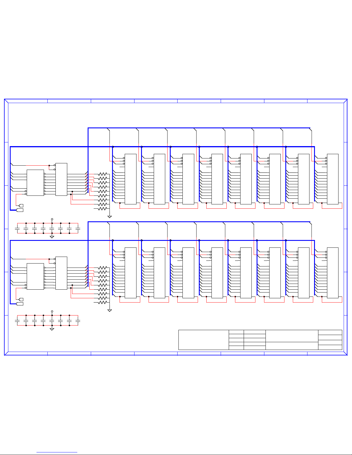
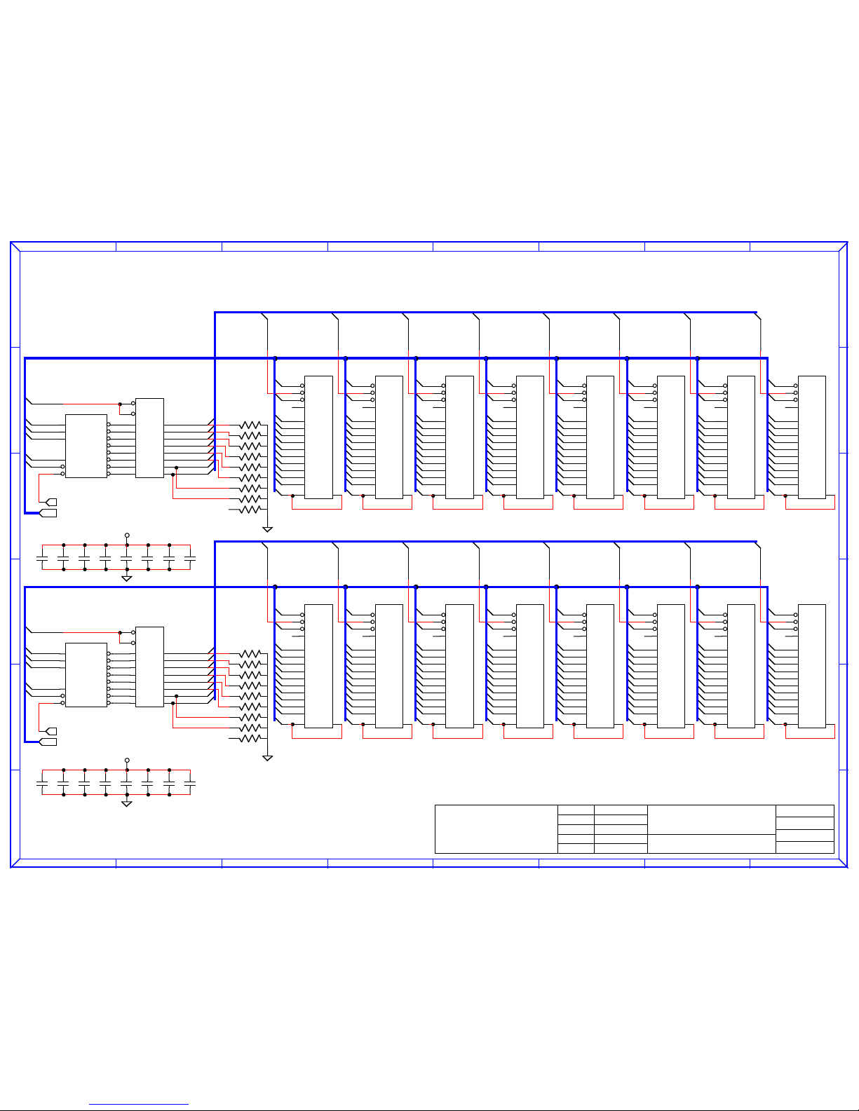
Schematic and Parts List................................................................. 16
Page 3

Warranty
FF Systems warrants its products to be free from defects for one year from the date of shipment.
FF Systems may opt to repair or replace (at our option) any defective product. FF Systems does
not warrant any defect due to lightning or other natural disaster. Any user modifications or repairs
to any product sold by FF Systems shall void this warranty. All returns must be accompanied by a
Return Material Authorization (RMA) number provided by FF Systems prior to shipment.
Shipments that do not have the proper return authorization prominently noted on the outside of the
package will not be accepted. The purchaser is responsible for all shipping charges for any service
procedure(s) performed by FF Systems (including warranty service).
30 Day Money Back Guarantee
FF Systems offers a 30 day trial period on all products. The 30 day trial begins 5 calendar days
after shipment from FF Systems. If the purchaser decides to return a product they must contact FF
Systems for a Return Material Authorization (RMA) number on or before 6:00pm central time
within 35 calendar days of the original shipment date. The purchaser then has fourteen additional
calendar days to return the merchandise to FF Systems. FF Systems claims no liability for lost or
mis-directed shipments. The purchaser is responsible for all shipping charges.
Product Condition
Products must be in new condition or warranty repairable to qualify for refund. If merchandise
incurs damage not covered under warranty, the refund will be delayed until the unit has been
repaired and the cost of that repair shall be deducted from the refund. FF Systems is not
responsible for damages incurred during shipment -- the purchaser should insure the merchandise
for the purchase amount to avoid possible loss due to damage during shipment.
Contact Address
FF Systems
P.O. Box 5533
Round Rock, TX 78683
512-365-1120 (voice)
e-mail:[email protected]
web: http://www.rollanet.org/~joeh/
1
Page 4

Introduction
The FF-8070 DVR (Digital Voice Recorder) is a microprocessor controlled audio record and
playback interface designed for the FF-800 Repeater Controller. The FF-8070 accepts DTMF
commands and audio via the FF-800 and includes provisions for record or playback from the FF800 control autopatch. The recording of messages is divided into three areas: 1) System tracks, 2)
Voice mail, and 3) Audio test. System messages are primarily used by the FF-800 (as assigned by
the user) to play DVR tracks in ID bulletins, function annunciators, tail messages, etc.... The
voice mail and audio test features are primarily for use by repeater users via DTMF commands.
The voice mail feature allows users to record and receive messages. The status of the mail box can
be interrogated manually (allowing users to interrogate the mailbox to see if they have any
messages), or the FF-800 may automatically poll the mailbox status via speech macro commands.
The audio test records a sample of audio up to 20 seconds long on a test track and immediately
replays the test track to provide users with a means of monitoring their signal quality -- this feature
is also useful for adjusting the DVR levels after installation.
It should be noted that the system tracks and the mail box tracks are separate and there are different
command sets to record and play the two types of tracks. NOTE: the audio test and mail box
tracks can not be directly accessed by the FF-800 speech macro commands. Speech macros are
special "words" that are used in FF-800 messages to trigger the DVR play a track.
Operation Overview
The FF-8070 DVR uses Continuously Variable, Slope-Delta (CVSD) modulation to store audio
signals as a stream of single bit values. The system must over-sample to eliminate the carrier
frequency -- in this case the sample frequency is 50KHz. The bit stream is stored on 1 megabit
DRAMS each of which can hold about 20 seconds of sampled audio. The FF-8070 comes
standard with 8 one megabit DRAMS with room for additional memory (up to a maximum total of
32 DRAMS).
The DVR memory architecture is organized as 8 banks of 4 DRAMS each, which means that you
should add memory to the DVR in blocks of 4 devices at a time. The memory expansion connector
(P1) allows the FF-8070EXP memory expansion board to be installed which allows an additional
32 DRAMS for a total of 64 megabits of storage (over 21 minutes of total audio record time). The
DVR separates the banks of memory into "system" and "mailbox" areas. By selecting how many
mailbox tracks you desire (# MAIL Tracks, command suffix <053>), the system will allocate
the number of banks available to the system tracks. Note that the mailbox tracks are selected at the
expense of system track memory. The factory defaults is to select 3 mailbox tracks. This takes
one bank of DRAM, which leaves one bank available for system tracks (given the 8 DRAMs that
are factory standard).
There are 100 system tracks available (7 of which are used as prompts for the voice mail) and these
tracks reside in the system section of the DVR memory. The FF-8070 DVR is a random access
system, which means that tracks can be recorded and rerecorded as often as desired without any
special consideration for any previous record operations. The only stipulation is that the maximum
record time of each track can not be exceeded. Each track is allocated a certain maximum record
time, this time can range from one second up to 83 seconds for an individual track. Each track is
preallocated at the factory but the user can modify the record time allocations for the system tracks
to meet their special needs. Tracks can be reallocated after the DVR has been in service, but all
reallocated tracks must be rerecorded -- appendix B discusses the allocation process in more detail.
The mail box section holds the mail box tracks as well as the DVR test track. Thus, if the user
2
Page 5

turns off the mail box (by selecting 0 mailbox slots), the DVR test feature is also disabled. If the
mail box is turned off, the seven prompt tracks can be used as general system tracks. On power
up, the DVR clears all tracks (but not configuration data like prefixes, record time allocations,
etc..., these are maintained in nonvolitile memory). Thus, the mail box prompt tracks must be
recorded after power up in order for the mail box prompts to function properly. A battery back-up
connector is provided to maintain the DVR speech memory in the event of a power failure. The
installation section discusses the connection of an appropriate battery.
Installation
The wiring of the DVR is accomplished through three connectors on the FF-8070 board. The
following lists those connectors along with their signal descriptions: ~ = Active low signal
P2: Battery * P3a: DVR I/O * P3 (legacy) P5: SPI Bus * P3: DVR I/O
(molex 3 pin) (IDC 10 pin) (molex 9 pin ) (IDC 10 pin) (2 pin header)
1) Battery (-) 1) DVR in (A) 1) DVR in (A) 1) MOSI
2) Battery (+) 2) GND 2) GND 2) GND 2) GND
3) Battery (-) 3) DVR out 3) ~CMD unlock 3) SPCK 3) ~CMD unlock
4) GND 4) n/c 4) GND
5) GND 5) n/c 5) MISO
6) GND 6) DVR in (B) 6) GND
7) DVR in (B) 7) DVR out 7) ~RST1
8) +12V in 8) +12V in 8) n/c
9) GND 9) GND 9) n/c
10) +12V in 10) Reset
* Note: legacy P3 connector supports FF-800 controllers manufactured prior to 2001 and is
generally not installed.
P1 & P4 are for DVR expansion and their pin-outs are detailed in the schematic for user reference.
The battery input (P2) should be connected to a battery for maintaining DVR operation during
power interruptions. The battery must be greater than 9 volts accross its discharge cycle, and less
than the voltage at P3-8 for proper operation. A 3 AHr lead-acid-cell will maintain power for over
30 hours. It is generally recommended that a 12V battery be used with at least 1Ahr of capacity.
Note that the FF-8070 has no provisions for charging the back-up battery, an external
charge/maintenance system must be supplied by the user.
P3a and P5 use factory supplied ribbon cables to connect to the FF-800. P3a on the DVR connects
to P25 on the FF-800, while P5 on the DVR connects to P7 on the FF-800.
The FF-8070 card should be placed in an RF tight enclosure and be placed as close as practical to
the FF-800. It is recommended that the FF-8070 be installed in the same chassis as the FF-800 to
allow the cable lengths to be kept to a minimum.
DVR Functions
The FF-800 SPI interface commands use a prefix-suffix syntax. The user-defined prefixes may be
1 to 4 digits long and are used to access the various interfaces connected to the FF-800 SPI bus.
The SPI protocol assigns a fixed address to each interface that is connected to the bus. These
addresses are factory defined and are used to differentiate the devices (the FF-800 does not have
any specific programming that differentiates one address from another). The DVR address is 6, so
the FF-800 commands for accessing the DVR are the SPI #6 Command (default 130) or the
generic SPI Command plus the address "6" (default 1266). One of these prefixes must precede
3
Page 6

the DVR commands described herein. Note that these prefixes are defined using the FF-800, not
FF-8070 commands. If they have been modified for your system, you must use the new prefix
when entering DVR commands into your system (all examples illustrate the default prefix codes).
The suffix codes form the "tail end" of the DVR command syntax. These are the DTMF digits that
specify which DVR command is to be executed and may include one or more digits of user
specified data. In addition, four of these suffix codes can be user defined as shown below.
User Defined suffixes: Factory Default
Record mail slot *
Erase last played mail slot **
Audio Test ***
List active Mail Slots blank (no digits)
The following list describes the FF-8070 command suffixes. These commands are used to set
system parameters or record system tracks. NOTE: all DVR command digits must be preceded by
a FF-800 SPI prefix digits:
suffix code DESCRIPTION
00 Play system track
01 Record system track.
01* Interrogate system track size.
02 Set input source. Selects main or aux. (phone patch) DVR input.
03* System track erase.
040 Search system track -- short play.
041 Search system track -- long play.
050 lopoff (start) configure.
051 End lopoff (end) configure.
052 Set number of installed DRAMs.
053 Set number of mailbox tracks.
054 Set "Audio Test" suffix.
055 Set "List active slots" suffix
056 Set "Record mail" suffix
057 Set "Erase last played" suffix
0580 Set Voice Mail Auto-play delay time.
0581800 Clear user defined suffixes
0582 Set Voice Mail Auto-erase time.
059 Blank annunciate mode.
05* Set Security code.
060800 Execute BASIC initialization.
061 ADVANCED initialization code.
066 Force mail box message erase
067800 Save configuration flag modes.
069 Set track interrupt mode.
07 Record system track with no play-back
08 Version request. Responds with the interface model and serial number.
09 Security lock/unlock
User Commands
Input Source Set Sets source of record audio to the DVR (main or aux)
<spi prefix> + <02> ; <1 or 2> 1 = main, 2 = aux
default 13002 interrogate
4
Page 7

The auxiliary DVR input is intended for use by the FF-800 control autopatch. This signal is available on
the FF-800 P20. When executing this command, the DVR response will be "In A" if the selected input
source is main, or "In B" if auxiliary. As long as the input source = aux, the normal COS detection for the
DVR is suspended and the DVR looks for a DTMF digit to simulate a COS signal. Any time the DVR
would normally look for a COS, it will now look for any DTMF digit. Recording starts as soon as the
digit is released. Loss of COS is simulated by another DTMF DIGIT (again, it may be any digit) and
recording stops as soon as the digit is detected. Also, as long as source = aux, a DTMF digit press will
interrupt any playback in progress. If no record or playback command is received for 5 minutes, the
source will automatically revert to main. The letter "B" is appended to the "DVR" and "Test" prompts for
the Record system track, and Audio Test functions when source = aux.
Audio Test Record and play-back test track.
<spi prefix> + <Audio Test suffix>
default 130***
This function waits for a COS signal (or any DTMF digit if input = aux.) to begin recording on the
test track. After the loss of COS (or another DTMF digit, if input = aux.), the test track is played
back. The maximum record time for the test track is 20 seconds. There is a time-out limit of 5
seconds after the command entry -- if no COS is engaged within this time, the record operation is
aborted.
Voice Mail Send, Receive, or List voice mail tracks.
List active mail slots <spi prefix> + <List active Mail Slots>
default 130
Record new mail <spi prefix> + <Record mail slot>
default 130*
Erase last-played slot <spi prefix> + <Erase last played mail slot>
default 130**
Play mail slot <spi prefix> + <slot#>
default 130n
There are two parts to a voice mail message, the first is the address header and the second is the
voice message itself. The address header is a brief description of to whom the message is intended
(i.e., the person's call sign, or "TO ALL HAMS", etc...). The maximum time for a mail track is
20 seconds which includes the message and address. The DVR uses system tracks 00 through 06
to prompt the entry of voice mail. If any of these tracks are empty, the FF-8070 will respond "M
P" (Mail Prompt) and the track number for the particular prompt in question. The following list
describes these special system track numbers and their prompt function:
5
Page 8

SYS TRACK # Track function: Examples:
• Track 00 message address prompt "Who is your message for"
• Track 01 record prompt "Record your message"
• Track 02 messages waiting "There are voice messages"
• Track 03 no messages "Sorry, there are no messages"
• Track 04 message clear "Your message has been erased"
• Track 05 message saved "Your message has been saved"
• Track 06 mailbox full "Sorry, the mailbox is full"
These tracks should be recorded after each cold-start (a cold start is when the DVR is powered on
after a full power loss). Note that any DVR recording will be lost if the DVR looses power at both
the normal and battery power connections. The mailbox function will still operate even if these
tracks are not recorded, but the prompting will not be informative to those who are not familiar
with the mail slot recording process.
After entering the record voice mail command, the DVR responds with track#00 ("who..."). The
user simply keys their transceiver, speaks an appropriate address, and then releases their push to
talk. The DVR then responds with track#01 ("record...") at which time the user keys again and
records their message. After the message is recorded (PTT released) the DVR responds with
track#05 ("message saved..."). The record cycle is now complete and the message can be
retrieved at any time by the addressee.
If all the available voice mail message slots are in use, the DVR will respond with track#06
("full...") instead of track#00. If this occurs, no more messages can be stored until one or more of
the active messages is erased. Also, there is a time-out limit of 5 seconds after each prompt -- if
no COS is engaged within this time, the mailbox operation is aborted.
To query the mail box, the "list active messages" command is entered. If there are no active
messages, the DVR responds with track#03 ("no messages..."). If one or more active messages
are present, the DVR reads back the slot number followed by the address header for each active
message. The slot number of the message headers is important in that this corresponds to the
number entered to retrieve the message track. NOTE: The DVR does not count inactive messages
during the list operation. This means that if a message is deleted, any active message numbers that
follow it will be decremented by one on subsequent list queries. Thus, a message track may start
at slot number 3, but end up at slot number 1 if the previous two messages are deleted (and no
other slots are recorded).
When the play message slot function is entered, the DVR looks for the n-th active message. If
active, the header and message are played-back. After the playback is complete, a 60 second timer
is activated during which the message erase function can be entered to clear the message track. If
the erase is successful, the DVR responds with track#04 ("message clear..."). If there is no
response to the erase command, then the erase was not successful.
Version Interrogate the FF-8070 software version.
<spi prefix> + <08>
default 13008
Responds with the interface software revision and serial numbers. This command is useful to
verify that the interface communications are functioning properly. The FF-800 Version
Interrogate command (01800) will also interrogate the FF-8070 version and serial numbers.
6
Page 9

Security Security access command
<spi prefix> + <09> ; <nnn> Unlock security access
default 13009 lock access
13009nnn unlock
This command must be entered prior to accessing the configuration commands if a security code has been
programmed. Entering the prefix with out the code, or with an invalid code, will lock the system (which
should be done after a configuration session is complete). The security access automatically expires 15
minutes after the last entry of a configuration command. It should be noted that this command is totally
unrelated to the FF-800 security commands. NOTE: If the security prefix is set to blank (no prefix), then
security is ALWAYS unlocked, and this command has no affect on the status of security. The factory
default is a blank security code.
Configuration Commands
NOTE: All configuration commands require that the DVR security be unlocked or disabled.
Set security code <spi prefix> + <05*d..d>
default 13005*d..d
response: "P F X" if new prefix is OK
"Abort" if new prefix is a duplicate of an existing prefix or if CMD unlock jumper
removed.
The security code "d..d" can be between 0 (blank) and 3 digits long. Zero digits for "d..d" disables the
security feature (this is the factory default). Note that the CMD unlock jumper (P3) must be installed to set
the security code.
Record system track <spi prefix> + <01nn> Record track #<nn>
<spi prefix> + <01*nn> Interrogate track length
<spi prefix> + <07nn> Record (no play-back)
default 13001nn record
13001*nn interrogate track length
13007nn record w/ no play-back
The record time of the new track can not exceed the allocated time or an error message will result
and the original track will be lost -- refer to appendix B for a listing of the BASIC initialization
allocations. The <01*nn> format allows the user to interrogate the amount of time allocated to the
indicated track. The response is in seconds and provides the user with a means to interrogate the
maximum length allocation for any track. The record protocol is as follows:
• Enter 13001nn (nn = track# to record) and wait for the "DVR" response from the
FF-8070(or "DVR B" if source = auxiliary) -- the DVR waits for a
COS signal (or any DTMF digit if input=B) at which point the recording
operation begins.
• Recording continues until the loss of COR (or any DTMF digit if input=B) or until
the end of track is reached. There is no alert for end of track over-run.
• After the record operation, the track is played back and the record cycle is complete
(this step is skipped for the no play-back command).
There is a time-out limit of 5 seconds after the "DVR" response -- if COS (or DTMF digit if
input=B) is not engaged within this time, the record operation is aborted with no change to the
original track.
7
Page 10

System track erase <spi prefix> + <03*nn>
default 13003*nn
Erases the system track# <nn> from the system. It is not necessary to erase a system message
before rerecording.
Force Mail Erase <spi prefix> + <066nn> Erase Mail box Track(s)
default 130066nn
Forces an erase of mail box message track number <nn> without having to interrogate the contents
of the mailbox slot. If there are not <nn> active messages, this command is ignored. If <nn> =
"0", all of the active messages are erased (leaving the mail box completely empty).
Play system track Play system track.
<spi prefix> + <00nn> Play track number "nn"
<spi prefix> + <041> ; <nn> Search tracks starting at track# "nn"
<spi prefix> + <040> ; <nn> Search tracks -- short play version
default 13000nn Play track
130040nn Search tracks, short
130041nn Search tracks
The search tracks formats are used to sequentially play a range of system tracks. The DVR starts at
track# <nn> (or track# 00 if <nn> is omitted) and sends the track number followed by a playback
of the track for each of the remaining tracks. This format is useful for locating a track if the
number has been forgotten. The search continues until a COS is detected or until the last recorded
track is encountered (blank tracks are skipped). The search long function plays each track in its
entirety, while the search short only plays the first 1 second of each track.
LOPSTART A <spi prefix> + <050> ; <nnn> Start lop-off: input A (milliseconds)
LOPEND A <spi prefix> + <051> ; <nnn> Stop lop-off: input A (milliseconds)
LOPSTART B <spi prefix> + <050*> ; <nnn> Start lop-off: input B (milliseconds)
LOPEND B <spi prefix> + <051*> ; <nnn> Stop lop-off: input B (milliseconds)
default 130050nnn Start, input A
130051nnn Stop, input A
130050*nnn Start, input B
130051*nnn Stop, input B
The "lop-off" values are the amount of time that subtracted from the beginning or end of each
recorded track. This allows the elimination of switching and squelch noise from the beginning
and/or end of tracks which gives a "clean finish" to the DVR tracks. If the system has a long
squelch burst, or some other artifact that is heard at the beginning and/or end of a recorded track,
then these values may be increased to remove the particular artifact. NOTE: it is not necessary to
rerecord tracks for new lop-off values to take affect, this value is used in play-back only, so the
values may be changed any number of times without altering the original track recordings.
LOPSTART A and LOPEND A affect all tracks recorded from the "A" input while
LOPSTART B and LOPEND B affect all tracks recorded from the "B" input. The Audio Test
track does not use the lop-off functions, so squelch noises or DTMF "blips" observed on this track
are normal.
8
Page 11

# DRAMS Installed <spi prefix> + <052> ; <nn> Set number of DRAMs installed
default 130052 interrogate current setting
130052nn set to "nn"
In order to properly store and retrieve tracks, the DVR firmware must know some information
about the hardware configuration of the interface. The number of installed DRAMS is preset at the
factory for the amount of memory that the DVR shipped with -- however, if additional memory is
later added, this value must be changed to reflect the number of DRAMs installed. Refer to
appendix C for details on adding DRAM.
# MAIL Tracks <spi prefix> + <053> ; <nn> Set number of mailbox tracks
default 130053nn interrogate current setting
130053 set to "nn"
This function should not be executed until after the # DRAMS Installed function is updated
(only required if there is a change in the DRAM configuration). The user may allocate mailbox
tracks within the following limits: 0, 3, 7, 11, 15, 19, 23, 27, or 31. If any other number for
<nn> is entered, an error will result. The selection of 0 mailbox tracks turns off the mailbox and
audio test functions. The mailbox allocation is restricted by the number of DRAMS installed. The
maximum number of mailbox tracks = #DRAMs - 5. Selecting a number greater than that given by
this equation will also result in an error. It should also be noted that adding mailbox tracks takes
away system tracks. Thus the user must balance the available memory with the requirements for
system tracks and mailbox tracks. If this balance is difficult to achieve, then it may be necessary to
add more memory.
Set User Defined Prefixes:
Set "Audio Test" suffix <spi prefix> + <054d..d>
Set "List active" suffix <spi prefix> + <055d..d>
Set "Record mail" suffix <spi prefix> + <056d..d>
Set "Erase mail" suffix <spi prefix> + <057d..d>
response: "P F X" if new prefix is OK
"Abort" if new prefix is a duplicate of an existing prefix.
The four mailbox codes can be between 0 (blank) and 3 digits long. These codes should not begin
with a numeric digit (although "0" is generally OK), and users can not duplicate any codes used for
configuration. The firmware compares the new <d..d> code with all of the existing system and mailbox
codes before validating the entry. Thus, none of the mailbox codes can duplicate any of the fixed,
configuration codes. For example: "130054052" would result in an error because the "052" prefix is
already used by the configuration codes. However, "05" is acceptable because this sequence does not
appear in any of the configuration codes (the match must be for all digits).
Blank Annunciate <spi prefix> + <059> ; <1/0> Enable/Disable blank track annunciate
default 130059 interrogate status
1300590 disable blank track announce
1300591 enable blank track announce
The blank annunciate flag allows the user to enable or disable the blank track annunciator. When
enabled, the blank track annunciator simply responds with "T N xx" (where xx = track #) any time
that a blank system track is played. If disabled, a blank track will not generate any response to a
play command. The factory default enables the blank track annunciator feature.
9
Page 12

Track Interrupt Mode <spi prefix> + <069> ; <mode> Enable/Disable play track interrupt
default 130069 interrogate
1300690 no interrupt
1300691 DTMF interrupt
1300692 COS interrupt
There are three interrupt modes available on the FF-8070:
RESPONSE DESCRIPTION
"I N T Cancel" <mode> = 0, No interrupt allowed -- all tracks will play to completion
"I N T D T M F" <mode> = 1, Only interrupt if a DTMF digit is detected
"I N T C O S" <mode> = 2, Interrupt if DTMF or COS detected during play
These modes allow the user to set the play interrupt mode for their DVR. <mode> = 1 is most
generally recommended for users who do not want COS interrupt of DVR tracks because it still
allows an interrupt mechanism that is available (pressing a DTMF digit) to terminate a track play if
desired.
Save Config. Flags <spi prefix> + <067800> Set configuration flags to EEPROM
default 130067800
This command "saves" the status of the configuration flags register. On reset, this register is
recalled from EEPROM so that the contents can continue to reflect the user's desired setting. The
configuration flags save the Blank annunciate flag and the interrupt mode. Changes made to these
settings will not be retained until saved with this command. Also, the auto erase time is saved with
this command.
Clear Mail Codes <spi prefix> + <0581800> Clear mail suffixes
default 1300581800
This command should be executed anytime that the voice mail command codes are to be changed. This
resets the function codes to the factory defaults which can help reduce difficulties that may be encountered
with the FF-8070 code checking procedure.
Auto Play delay <spi prefix> + <0580> ; <t> Set or interrogate the auto play delay
default 1300580t
This command is used to set the auto play delay from <t> = 0 to 9 minutes. The auto play delay
affects tracks 100 and 101 and prevents them from being played if a user enters the "List active
messages" command within the time set by this command. The factory default is 3 minutes.
Auto Erase delay <spi prefix> + <0582> ; <t> Set or interrogate the auto erase delay
default 1300582t
This command is used to set the auto erase delay from <t> = 0 to 255 hours. The auto erase time
is attached to each voice mail message when it is recorded. When the time expires, the message is
automatically erased. <t> = 0 hours disables the auto erase feature -- the factory default time is 255
hours, or a little over 10 days. This parameter must be saved using the Save Config. Flags
command.
FF-800 Interface Programming
The FF-800 allows any of the system tracks to be entered into speech messages on the FF-800 via the
"[SPI]" speech phrase macro (word# 182). When the message is processed by the FF-800, the
10
Page 13

appropriate DVR track is played to the repeater output. DVR tracks may be mixed with CW, repeater
speech, and repeater courtesy tones. Also, there are two special track numbers that can be used to
interrogate the status of the mail box (for ID bulletins, tail messages, etc...). These track numbers are as
follows:
track# Description
100 List all active headers. There is no response if there are no active slots in the mailbox .
101 If there are active mail slots, a play of track#101 responds with system track#02
("messages waiting..."). Otherwise, there is no response.
The syntax for the [SPI] phrase is "[SPI] a t" where "a" is the DVR SPI address (6) and "t" is the track
number to be played. The following examples illustrate speech phrase command entry on the FF-800:
From the terminal interface:
>MES 0 [SPI] 6 7 [SPI] 6 101 [SPI] 6 100 [SPI] S
[SPI] 6 7 [SPI] 6 101 [SPI] 6 100 [SPI] S
>
This message would be suitable for an ID bulletin and would play track 7 first (which would contain a
recording of the repeater ID) and then play track#02 if any mail box slots are active followed by a list of
the active mail box headers. The "[SPI] S" speech macro is used to suppress the repeater ID that follows
all ID bulletins. If the user wants the ID to occur (i.e., there is no ID recorded in the DVR track) then this
phrase macro would be omitted.
A sequence suitable for a tail message is as follows:
>MES 10 [SPI] 6 101
[SPI] 6 101
>
This will play track#02 if there are any mail box messages and can be assigned to a tail message to provide
an additional alert to users of mail box traffic.
The formats are similar if the message is programmed via the DTMF text editor. From the word list the
user can note that the [SPI] phrase macro is word# 182, and this is the number used to enter the phrase
macro.
enter the control security command, followed by the config security command.
enter "<cnfgpfx>580" -- response:"TXT Enter"
enter "182*6*7*182*6*101" -- response:"<track#7> < IF MAIL, then play track#2>"
enter "182*6*100*182*83*" -- response:"<IF MAIL, then list headers>"
Note: the code for "S" = 83, thus "182*83*" = the ID suppress macro. The parameter(s) following the
182 code must be entered in the same transmission of the text or they will not be parsed correctly. Also, if
there are no messages, or if the programmed track is not yet recorded, there will be no response for the
text interrogate functions.
Refer to the FF-800 manual for more information on text message entry and message management.
FF-8070 Command Examples
The FF-8070 is configured at the factory for the amount of memory installed, and the number of
mail box tracks is set to 3. The user may wish to modify the mail box assignments or change the
user defined command codes. The following examples illustrate how to modify the configuration
11
Page 14

and demonstrate the operation of the FF-8070. All examples assume that the FF-800 has its
default prefix designations:
The FF-8070 is configured at the factory for the amount of memory installed, and the number of mail box
tracks (3 mail box tracks is the factory default). The user may wish to modify the mail box assignments or
change the mail box command codes. The following examples illustrate how to modify the configuration
and demonstrate the operation of the FF-8070. All examples assume that the FF-800 has its default prefix
designations:
• Turn off the mail box and test track:
1300530
response: "Set M T Off"
• Set the number of mail box tracks to 3:
1300537
response: "Set M T Three"
• Set lop values
130017 record a test track
response: "D V R" after track is recorded, the 8070 will replay to verify
130051200 set lop end to 200ms (0.2 sec)
response: "Set Stop Two Hundred"
130022 set aux input
response: "Set In B"
13005160 set aux lop end to 60ms (0.06sec)
response: "Set Stop B Sixty"
130021
response: "Set In A"
• Set configuration password code
Ground P3-3
13005*159 set pass code to "159"
response: "P F X"
13009 lock security
response: "O K"
130051 try to interrogate lop end
response: none
130*** do DVR test
response: "Test"
13009159 unlock security
response: "O K"
130051
response: "Stop Two Hundred"
13005* clear pass code
response: "P F X"
Be sure to remove the jumper from P3-3 after the pass code has been programmed -- note that this
connection is not required to unlock security, it is only required to allow the security code to be
changed.
12
Page 15

Adjustments
The FF-8070 is adjusted at the factory to balance the record level between the main and aux.
inputs. Note that the FF-8070 should not require adjustment by the user once the FF-800 and
repeater levels have been adjusted. The following procedure is for reference in the event that
adjustments become necessary.
There are two input level adjustments on the FF-8070: VR1 is the main input level, and VR2 is the aux
input level (VR3 is not installed). Refer to the parts placement diagram in appendix B for locating these
controls. The simplest means for adjusting the DVR is to use the DVR audio test function to record/play
test tracks and an oscilloscope connected to one of the FF-800 audio outputs (P4-1, 3, 5, or 7) or a service
monitor on the controller output -- if neither instrument is available, use an amplified speaker or receiver
tuned to the repeater output. While recording, monitor the signal level on the scope and compare this to
the playback level. If VR1 is properly adjusted, the playback from the DVR will have the same level as the
record operation. Repeat this process while adjusting VR1 until the record and play levels are as close as
possible.
The aux input level (VR2) is slightly more difficult to adjust since the DVR audio is redirected to the phone
during a control autopatch. Also, if a second telephone is not available at the repeater site, another person
must assist from a remote location to provide control commands and test audio over the control autopatch.
For this adjustment use an oscilloscope or an amplified speaker to monitor the DVR audio at P3-7. Adjust
VR1 First and then have the operator that will be on the control autopatch record a test message in one of
the system tracks (use the main input for this track). When the operator establishes the control autopatch
connection, they must issue the Input Source Set command to switch the DVR to the aux input (<spi6
#22>). The operator on the control autopatch will alternately perform an Audio Test and Play system
track of the test track recorded earlier. By comparing the track recorded from the "main" input with the
test track from the "aux" input, the person at the repeater site can adjust VR2 to balance the two inputs.
The operator on the control patch must continuously rerecord the Audio Test track so that the new input
level can be compared to the main input level (via the Play system track command). Also, note that the
aux audio is affected by digital POT#6 on the FF-800, and therefore this adjustment should be completed
prior to adjusting VR2 on the DVR.
13
Page 16
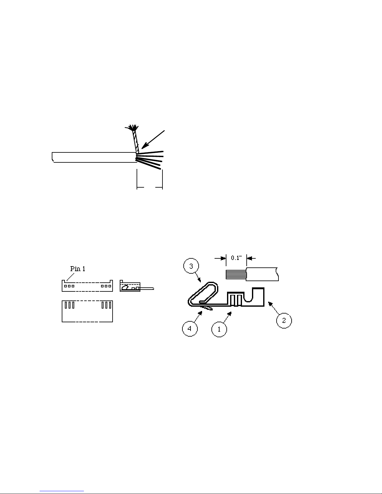
APPENDIX A: FF-8070 WIRING
The connections to the FF-8070 are all accomplished via 10 conductor ribbon cable. There are two
cables provided, one for the power/audio (connects P3 on the DVR to P25 on the FF-800) and one
for SPI communications (connects P5 on the DVR to P7 on the FF-800). The only remaining
connection is that of a back-up battery to P2 of the DVR.
For external connections, use shielded or twisted pair cable along with the provided housings and
crimp pins. Cut the cable to the shortest possible length and strip back the outer sheath 1 inch.
Unravel the braid and twist together as shown below and remove the foil inner shield (if present).
Solder hook-up wire here
1"
Solder a short piece (1 or 2 inches) of hookup wire to the shield as shown above and cut off the
remainder of the shield. Cut this wire even with the others and trim 0.1" of insulation from the end
of each wire. Using a pair of needle-nose pliers, crimp the exposed conductor into a molex pin as
shown at (1) below. Apply a small amount of solder to establish a good connection. If too much
solder is applied, it could wick down to the end of the pin at (4) -- this will make the pin difficult to
insert and it may not retain properly. If this occurs, the pin should be discarded and another
installed in its place. After all pins are secured, crimp at (2) around the insulation for strain relief.
Molex housing
The shield wire should connect to the GND connection of the specific housing. When inserting the
pin into the housing, be sure that the contact loop at (3) is oriented toward the tabs on the housing
as shown above.
Molex pin detail
14
Page 17

APPENDIX B: FF-8070 Track Allocation
The track allocation command <061> is used to more finely define the allocation of DVR memory.
The basic allocation command <060800> is executed at the factory and allocates the 100 system
tracks as 10 banks of 10 tracks each. In each bank, the first six tracks are 5.9 seconds long, while
the remaining four are 11.9 seconds long. With this allocation scheme, the only way to get access
to all 100 tracks is to add the FF-8070EXP expansion memory card. However, most applications
do not require this much memory, so all that is required is to reallocate some or all of the system
memory.
The first step is to determine how many tracks of different lengths are required. Use the
<061*nn> code to de-allocate all tracks starting with and following track number "nn" -- it is
usually advisable to start at track "00" and reallocate all tracks at once, but this is not required. The
<061nn*tt> code is used to allocate <nn> tracks at <tt> seconds each. This continues until all
desired tracks are allocated, or until the 100th track is allocated (at which point the DVR will no
longer accept allocation inputs and an "Abort" response is sent). The "Abort" response simply
means that all of the 100 system tracks have been allocated. The reallocation process should be
done before recording tracks because each reallocated track is erased in the process. The allocation
data is stored in nonvolitile memory which is specified to maintain data for up to 10 years. Thus,
if the DVR looses power, the tracks must be rerecorded, but the time allocations are retained.
APPENDIX C: Adding DRAM
Adding memory to the DVR is relatively simple. However, the process requires that all power be
removed from the DVR board -- this will necessitate that all tracks be rerecorded after the memory
is added. Memory is added in groups of four 1 Megabit DRAMS (411000, 511000, or equivalent)
as follows:
first group: U1, U11, U21, & U31
second group: U2, U12, U22, & U32
::
::
last group: U8, U18, U28, & U38
Any supplier of computer memory is likely to supply the DRAMS used on the FF-8070. The
access time is not critical (anything faster than 120ns is sufficient). FF-Systems can also provide
additional memory if another source is not available.
After the installation, the user must execute the DRAMS Installed and MAIL Tracks
commands to tell the DVR how much memory is installed and to reconfigure the mail box system.
MAIL Tracks must be executed even if there is no change to the number of voice mail tracks.
For systems that require more memory than the 10 minutes available on the FF-8070, a memory
expansion card is available that piggy-backs on to the FF-8070 (part# FF-8070EXP). This card
provides room for an additional 32 DRAMS or about 10 more minutes of record time. Contact FFSystems for more information.
15
Page 18

APPENDIX D: Schematic and Parts List
FF-8070 Parts List
C1 - 32, 37, 41, 61 0.1 µF ceramic capacitor, 50V
C33, 36, 38, 39, 42 1.0 µF nonpolarized electrolytic capacitor, 35V
C34, 35 100 pF ceramic capacitor, 50V
C44, 57, 58, 59 10 µF electrolytic capacitor, 25V
C51 330 µF electrolytic capacitor, 35V
C52, 53, 56 100 µF electrolytic capacitor, 25V
R1 10M Ω, 1/4 watt resistor
R2 510 Ω, 1/4 watt resistor
R3 470 Ω, 1/4 watt resistor
R4 1K Ω, 1/4 watt resistor
R5, 6, 7 20K Ω, 1/4 watt resistor
R8, 10, 15, 16, 19, 20 10K Ω, 1/4 watt resistor
R9 5.1K, 1/4 watt resistor
R13 100 Ω, 1/4 watt resistor
R21 10 Ω, 1/4 watt resistor
R24, 25 330 Ω, 1/4 watt resistor
R17, 36, 37 20K Ω, 1/8 watt SMD resistor, 1206 type package
R38 1M Ω, 1/8 watt SMD resistor, 1206 type package
VR1 - 2 10K Ω potentiometer
RP1 - 4 1.5K x 9 resistor pack, common bus
RP5 - 6 10K x 5 resistor pack, common bus
D1, 2, 6 1N4001 Diode, 50PIV
D7 1N4735, 6.2 V zener diode, 1/2 watt
Q1 PN2907A PNP transistor
Z1 15V tranzorb circuit protector
Y1 4.00MHz ceramic resonator
U1 - 8, 11 - 18, 21 - 28, 31 - 38 411000 1 M x 1 bit DRAM I.C.
U9, 19, 29, 39 74HC244 Octal bus driver I.C.
U10, 20, 30, 40 74HC138 1 of 8 decoder I.C.
U43 TMS3478NL CVSD record/playback I.C.
U44 MC68HC711E9-CFN2 microprocessor I.C.
U45 LM7805 +5V regulator I.C.
U46 MF4-50 switched capacitor filter I.C.
U47 LF353 op-amp I.C.
U49 4002 Dual 4 input NOR gate I.C.
U50 4066 quad analog switch I.C.
U51 ICL7660 dc-dc converter I.C.
U52 MC34064P-5 voltage monitor I.C.
U53 4040 ripple counter I.C.
P2 3 pin Molex header
P3 2 pin jumper header (9 pin Molex on some boards)
P3a 10 pin IDC header
P5 10 pin IDC header
16
Page 19
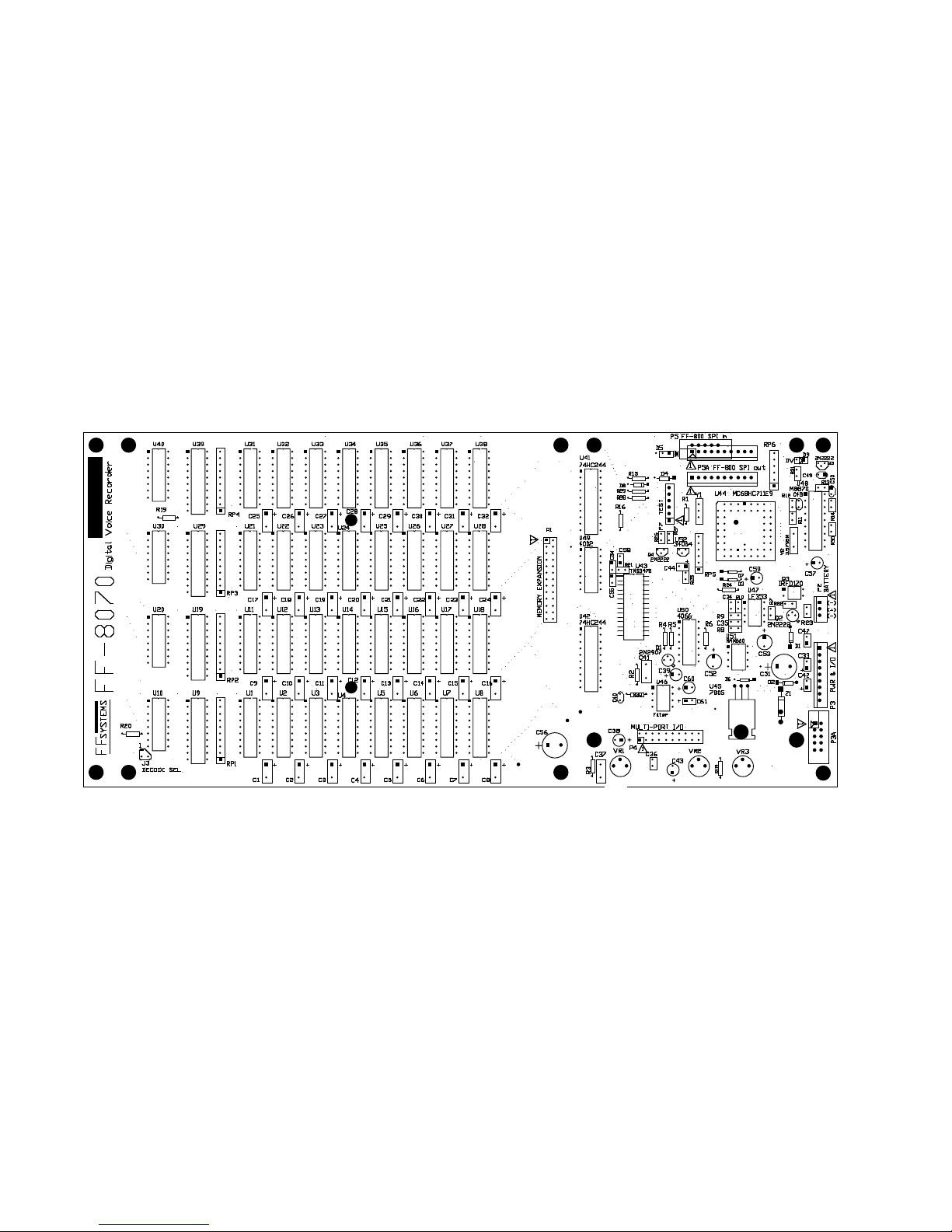
FF-8070 Component Layout
Page 20
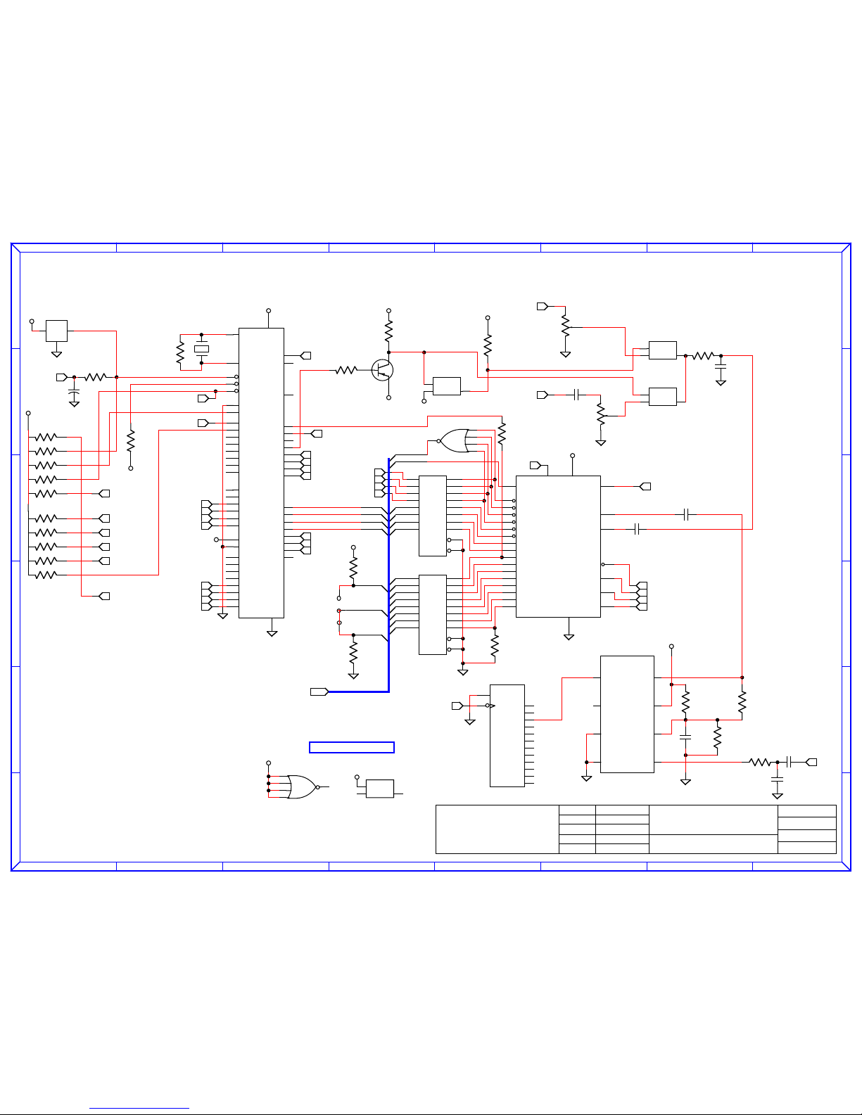
A
A
B
B
C
C
D
D
E
E
F
F
G
G
H
H
1 1
2 2
3 3
4 4
5 5
6 6
jmh
jmh
6/30/95
6/30/95
F
P.O. Box 5533 512-365-1120 (v)
Round Rock, TX 78683
[email protected]
www.rollanet.org/~joeh/
12/14/02
REV:FF-8070 D.V.R.
UNUSED DEVICES
"Affordable Repeater Control Solutions"
SystemsFF
FF Systems
8070.schem
B
Rel. date
chk'd by
Des. chk
Date
Drawn
by
Page
size
TITLE:
SHT 1 OF 4
+5V
Y1
4.00M
R1
10M
+v
rst
gnd
3
21
U52
34064
+5V
C44
10uF
~reset
XTAL
EXTAL
~RESET
~IRQ
~XIRQ
MODA/LIR
MODB/VSTBY
AS
VRH
VRL
PA0
PA1
PA2
PA3
PA4
PA5
PA6
PA7
PB0
PB1
PB2
PB3
PB4
PB5
PB6
PB7
PC0
PC1
PC2
PC3
PC4
PC5
PC6
PC7
E
R/~W
PD0
PD1
PD2
PD3
PD4
PD5
PE0
PE1
PE2
PE3
PE4
PE5
PE6
PE7
Vcc
Gnd
8
7
17
19
18
3
2
52
51
34
33
32
31
30
29
28
27
5
6
42
41
40
39
38
37
36
35
9
10
11
12
13
14
15
16
4
20
21
22
23
24
25
43
45
47
49
44
46
48
50
26
1
68HC711E9
U44
+5V
220
R25
sck
si
so
rst
Ain
Aout
mck
AP0
AP1
AP2
AP3
AP4
AP5
AP6
AP7
AP8
AP9
we
ras
cas4
cas3
cas2
cas1
data
V
c
c
A
V
c
c
G
N
D
TMS3478
8
9
10
5
2
3
6
281
18
19
20
21
22
23
24
25
26
27
15
17
14
13
12
11
16
4
U43
/G
A1
A2
A3
A4
Y1
Y2
Y3
Y4
/G
A5
A6
A7
A8
Y5
Y6
Y7
Y8
19
2
17
4
15
18
3
16
5
1
6
13
8
11
14
7
12
9
74HC244
U41
/G
A1
A2
A3
A4
Y1
Y2
Y3
Y4
/G
A5
A6
A7
A8
Y5
Y6
Y7
Y8
19
2
17
4
15
18
3
16
5
1
6
13
8
11
14
7
12
9
74HC244
U42
2
3
4
5
1
4002
U49a
A8
A9
~W
~R
D
REFCAS
A0
A1
A2
A3
A4
A5
A6
A7
BNK3
BNK2
BNK1
BNK0
SELP0
SELP1
~Drst
~CAS1
~CAS2
~CAS3
~CAS4
~MPT
Dsi
Dck
~RQ0
~RQ1
~RQ2
~RQ3
R16
10K
10K
R15
BNK3b
BNK3a
R19
10K
R20
10K
3
1
2
J3
BNK3
+5V
MISO
MOSI
SPCK
~RST1
2
3
4
5
6
1
RP5
10K
2
3
4
5
6
1
10KRP6
~MPT
~RQ0
~RQ1
~RQ2
~RQ3
~SECUR
+5V
~Sreset
1M
CONT
I/O O/I
12
10 11
dU50
4066
CONT
I/O O/I
13
12
4066
aU50
0.1
C41
530
R2
C42
1.0
DVo
Dck
Dsi
Dso
~Drst
1M
1K
R4
2N2907
Q1
+5V
20K
R5
CONT
I/O O/I
5
43
bU50
4066
-5V
-5V
R6
20K
aaud
470
R3
C37
0.1
+5V
9
10
11
12
13
4002
U49b
+5V
CONT
I/O O/I
6
89
4066
U50c
-5V
+5d
+5V
R17
10K
+5V
busy
"A" Level
10K
VR1
DVi
C36
1.0
"B" Level
VR2
10K
C38
1.0
Dso
+5V
MEMBUS
RP5res
C39
1.0
R37
20K
R36
20K
C45
0.1
Vss
LS
CLKR
CLKIN
Vo
Agnd
Vdd
Vi
MF4
4
3
2
1
5
6
7
8
U46
R38
1M
CLR
CLK
QA
QB
QC
QD
QE
QF
QG
QH
QI
QJ
QK
QL
11
10 9
7
6
5
3
2
4
13
12
14
15
1
U53
4040
1M
RATE32
Page 21
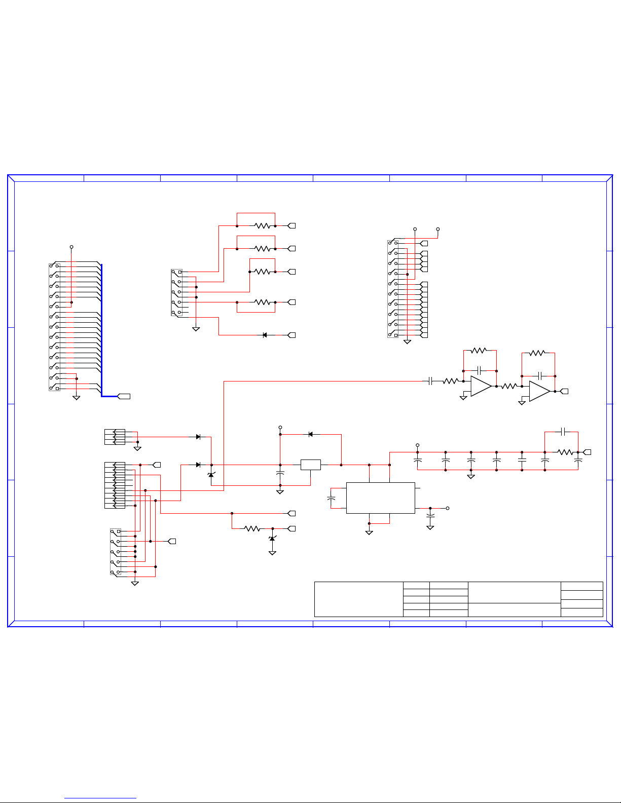
A
A
B
B
C
C
D
D
E
E
F
F
G
G
H
H
1 1
2 2
3 3
4 4
5 5
6 6
FF Systemsjmh
jmh
6/30/95
6/30/95
F
P.O. Box 5533 512-365-1120 (v)
Round Rock, TX 78683
[email protected]
www.rollanet.org/~joeh/
12/14/02
SHT 2 OF 4
REV:
FF-8070 D.V.R.
CW out
"Affordable Repeater Control Solutions"
SystemsFF
8070.schem
B
Rel. date
chk'd by
Des. chk
Date
Drawn
by
Page
size
TITLE:
B(+)
B(-)
B(-)
CMD lock
GND
GND
+12V in
MAIN in
DVR out
AUX in
1
2
3
4
5
6
7
8
9
10
11
12
13
14
15
16
17
18
19
20
21
22
23
24
25
26
P1
MEM EXP
1
2
3
4
5
6
7
8
9
10
11
12
13
14
15
16
17
18
19
20
P4
MULTI-PORT
D
~W
A9
~R
A8
A0
A7
A1
A6
A2
A5
A3
A4
REFCAS
~CAS3
BNK0
~CAS2
BNK1
~CAS0
BNK2
~CAS1
BNK3
+5V
MEMBUS
MOSI
SPCK
MISO
~RST1
SELP0
SELP1
IOA
IOB
IOC
IOD
DVRo
~RQ0
~RQ1
~RQ2
~RQ3
~MPT
+5V -5V
+
6
5
7
bU47
LF353N
R8
10K
R7
20K
R9
5.1K
+
2
3
1
aU47
LF353N
C34
100pF
C35
100pF
C1-
C1+
VO
OSC
VccFC
GND
LV
ICL7660
2
4
81
5
7
36
U51
1
2
3
U45
LM7805
C52
100uF
C51
330uF
T
P6KE15
Z1
D2
1N4001
D1
1N4001
1
2
3
4
5
6
7
8
9
P3
DVR I/O
1
2
3
P2
BATTERY
~SECUR
DVo
C53
100uF
-5V
~Sreset
~RST1
MISO
SPCK
MOSI
aaud
C56
100uF
C57
10uF
C58
10uF
C59
10uF
0.1uF
C55
+5V
1uF
C33
0.1uF
C54
10
R21
0.1uF
C60
+5d
1N4735
D3
330
R24
RP5res
D6
1N4001
C61
10uF
R10
10K
+12V
D4
1N4001
DVi
1
2
3
4
5
6
7
8
9
10
P3a
DVR I/O
100
R32
100
R33
100
R34
R35
n/u
1
2
3
4
5
6
7
8
9
10
SPI Bus
P5
Page 22
A
A
B
B
C
C
D
D
E
E
F
F
G
G
H
H
1 1
2 2
3 3
4 4
5 5
6 6
jmh
jmh
6/30/95
6/30/95
F
P.O. Box 5533 512-365-1120 (v)
Round Rock, TX 78683
[email protected]
www.rollanet.org/~joeh/
12/14/02
REV:
FF-8070 D.V.R.
"Affordable Repeater Control Solutions"
SystemsFF
FF Systems 8070.schem
0.1 µF (x8)
0.1 µF (x8)
* NOTE: PIN 4 OF ALL DRAMS IS TIED TO GND *
* NOTE: PIN 4 OF ALL DRAMS IS TIED TO GND *
SHT 3 OF 4
B
Rel. date
chk'd by
Des. chk
Date
Drawn
by
Page
size
TITLE:
/RAS
/CAS
/W
TF
A0
A1
A2
A3
A4
A5
A6
A7
A8
A9
DQ
3
16
2
4
5
6
7
8
10
11
12
13
14
15
117
511000
U2
A0
A1
A2
A3
A4
A5
A6
A7
A8
A9
D
~W
~R
/RAS
/CAS
/W
TF
A0
A1
A2
A3
A4
A5
A6
A7
A8
A9
DQ
3
16
2
4
5
6
7
8
10
11
12
13
14
15
117
U3
511000
A0
A1
A2
A3
A4
A5
A6
A7
A8
A9
D
~W
~R
/RAS
/CAS
/W
TF
A0
A1
A2
A3
A4
A5
A6
A7
A8
A9
DQ
3
16
2
4
5
6
7
8
10
11
12
13
14
15
117
U4
511000
A0
A1
A2
A3
A4
A5
A6
A7
A8
A9
D
~W
~R
/RAS
/CAS
/W
TF
A0
A1
A2
A3
A4
A5
A6
A7
A8
A9
DQ
3
16
2
4
5
6
7
8
10
11
12
13
14
15
117
U5
511000
A0
A1
A2
A3
A4
A5
A6
A7
A8
A9
D
~W
~R
/RAS
/CAS
/W
TF
A0
A1
A2
A3
A4
A5
A6
A7
A8
A9
DQ
3
16
2
4
5
6
7
8
10
11
12
13
14
15
117
U6
511000
A0
A1
A2
A3
A4
A5
A6
A7
A8
A9
D
~W
~R
/RAS
/CAS
/W
TF
A0
A1
A2
A3
A4
A5
A6
A7
A8
A9
DQ
3
16
2
4
5
6
7
8
10
11
12
13
14
15
117
U7
511000
A0
A1
A2
A3
A4
A5
A6
A7
A8
A9
D
~W
~R
/RAS
/CAS
/W
TF
A0
A1
A2
A3
A4
A5
A6
A7
A8
A9
DQ
3
16
2
4
5
6
7
8
10
11
12
13
14
15
117
U8
511000
A0
A1
A2
A3
A4
A5
A6
A7
A8
A9
D
~W
~R
/RAS
/CAS
/W
TF
A0
A1
A2
A3
A4
A5
A6
A7
A8
A9
DQ
3
16
2
4
5
6
7
8
10
11
12
13
14
15
117
U1
511000
A0
A1
A2
A3
A4
A5
A6
A7
A8
A9
D
~W
~R
A
B
C
G1
/G2A
/G2B
Y0
Y1
Y2
Y3
Y4
Y5
Y6
Y7
1
2
3
6
4
5
15
14
13
12
11
10
9
7
74HC138
U10
2
3
4
5
6
7
8
9
10
1
1.5Kx9
RP1
~CAS00
~CAS01
~CAS02
~CAS03
~CAS04
~CAS05
~CAS06
~CAS07
BNK0
BNK1
BNK2
BK3b
BK3a
/G
A1
A2
A3
A4
Y1
Y2
Y3
Y4
/G
A5
A6
A7
A8
Y5
Y6
Y7
Y8
19
2
17
4
15
18
3
16
5
1
6
13
8
11
14
7
12
9
74HC244
U9
REFCAS
~CAS00
~CAS01
~CAS02
~CAS03
~CAS04
~CAS05
~CAS06
~CAS07
MEMBUS
~CAS1
/RAS
/CAS
/W
TF
A0
A1
A2
A3
A4
A5
A6
A7
A8
A9
DQ
3
16
2
4
5
6
7
8
10
11
12
13
14
15
117
U12
511000
A0
A1
A2
A3
A4
A5
A6
A7
A8
A9
D
~W
~R
/RAS
/CAS
/W
TF
A0
A1
A2
A3
A4
A5
A6
A7
A8
A9
DQ
3
16
2
4
5
6
7
8
10
11
12
13
14
15
117
U13
511000
A0
A1
A2
A3
A4
A5
A6
A7
A8
A9
D
~W
~R
/RAS
/CAS
/W
TF
A0
A1
A2
A3
A4
A5
A6
A7
A8
A9
DQ
3
16
2
4
5
6
7
8
10
11
12
13
14
15
117
U14
511000
A0
A1
A2
A3
A4
A5
A6
A7
A8
A9
D
~W
~R
/RAS
/CAS
/W
TF
A0
A1
A2
A3
A4
A5
A6
A7
A8
A9
DQ
3
16
2
4
5
6
7
8
10
11
12
13
14
15
117
U15
511000
A0
A1
A2
A3
A4
A5
A6
A7
A8
A9
D
~W
~R
/RAS
/CAS
/W
TF
A0
A1
A2
A3
A4
A5
A6
A7
A8
A9
DQ
3
16
2
4
5
6
7
8
10
11
12
13
14
15
117
U16
511000
A0
A1
A2
A3
A4
A5
A6
A7
A8
A9
D
~W
~R
/RAS
/CAS
/W
TF
A0
A1
A2
A3
A4
A5
A6
A7
A8
A9
DQ
3
16
2
4
5
6
7
8
10
11
12
13
14
15
117
U17
511000
A0
A1
A2
A3
A4
A5
A6
A7
A8
A9
D
~W
~R
/RAS
/CAS
/W
TF
A0
A1
A2
A3
A4
A5
A6
A7
A8
A9
DQ
3
16
2
4
5
6
7
8
10
11
12
13
14
15
117
U18
511000
A0
A1
A2
A3
A4
A5
A6
A7
A8
A9
D
~W
~R
/RAS
/CAS
/W
TF
A0
A1
A2
A3
A4
A5
A6
A7
A8
A9
DQ
3
16
2
4
5
6
7
8
10
11
12
13
14
15
117
U11
511000
A0
A1
A2
A3
A4
A5
A6
A7
A8
A9
D
~W
~R
A
B
C
G1
/G2A
/G2B
Y0
Y1
Y2
Y3
Y4
Y5
Y6
Y7
1
2
3
6
4
5
15
14
13
12
11
10
9
7
U20
74HC138
2
3
4
5
6
7
8
9
10
1
RP2
1.5Kx9
~CAS10
~CAS11
~CAS12
~CAS13
~CAS14
~CAS15
~CAS16
~CAS17
BNK0
BNK1
BNK2
BK3b
BK3a
/G
A1
A2
A3
A4
Y1
Y2
Y3
Y4
/G
A5
A6
A7
A8
Y5
Y6
Y7
Y8
19
2
17
4
15
18
3
16
5
1
6
13
8
11
14
7
12
9
U19
74HC244
REFCAS
~CAS10
~CAS11
~CAS12
~CAS13
~CAS14
~CAS15
~CAS16
~CAS17
MEMBUS
~CAS1
C1 C2 C3 C4 C5 C6 C7 C8
+5V
C9 C10 C11 C12 C13 C14 C15 C16
+5V
Page 23
A
A
B
B
C
C
D
D
E
E
F
F
G
G
H
H
1 1
2 2
3 3
4 4
5 5
6 6
jmh
jmh
6/30/95
6/30/95
F
P.O. Box 5533 512-365-1120 (v)
Round Rock, TX 78683
[email protected]
www.rollanet.org/~joeh/
12/14/02
REV:
FF-8070 D.V.R.
"Affordable Repeater Control Solutions"
SystemsFF
FF Systems 8070.schem
0.1 µF (x8)
0.1 µF (x8)
* NOTE: PIN 4 OF ALL DRAMS IS TIED TO GND *
* NOTE: PIN 4 OF ALL DRAMS IS TIED TO GND *
TITLE:
Page
size
Drawn
by
Date
Des. chk
chk'd by
Rel. date
B
SHT 4 OF 4
/RAS
/CAS
/W
TF
A0
A1
A2
A3
A4
A5
A6
A7
A8
A9
DQ
3
16
2
4
5
6
7
8
10
11
12
13
14
15
117
U22
511000
A0
A1
A2
A3
A4
A5
A6
A7
A8
A9
D
~W
~R
/RAS
/CAS
/W
TF
A0
A1
A2
A3
A4
A5
A6
A7
A8
A9
DQ
3
16
2
4
5
6
7
8
10
11
12
13
14
15
117
U23
511000
A0
A1
A2
A3
A4
A5
A6
A7
A8
A9
D
~W
~R
/RAS
/CAS
/W
TF
A0
A1
A2
A3
A4
A5
A6
A7
A8
A9
DQ
3
16
2
4
5
6
7
8
10
11
12
13
14
15
117
U24
511000
A0
A1
A2
A3
A4
A5
A6
A7
A8
A9
D
~W
~R
/RAS
/CAS
/W
TF
A0
A1
A2
A3
A4
A5
A6
A7
A8
A9
DQ
3
16
2
4
5
6
7
8
10
11
12
13
14
15
117
U25
511000
A0
A1
A2
A3
A4
A5
A6
A7
A8
A9
D
~W
~R
/RAS
/CAS
/W
TF
A0
A1
A2
A3
A4
A5
A6
A7
A8
A9
DQ
3
16
2
4
5
6
7
8
10
11
12
13
14
15
117
U26
511000
A0
A1
A2
A3
A4
A5
A6
A7
A8
A9
D
~W
~R
/RAS
/CAS
/W
TF
A0
A1
A2
A3
A4
A5
A6
A7
A8
A9
DQ
3
16
2
4
5
6
7
8
10
11
12
13
14
15
117
U27
511000
A0
A1
A2
A3
A4
A5
A6
A7
A8
A9
D
~W
~R
/RAS
/CAS
/W
TF
A0
A1
A2
A3
A4
A5
A6
A7
A8
A9
DQ
3
16
2
4
5
6
7
8
10
11
12
13
14
15
117
U28
511000
A0
A1
A2
A3
A4
A5
A6
A7
A8
A9
D
~W
~R
/RAS
/CAS
/W
TF
A0
A1
A2
A3
A4
A5
A6
A7
A8
A9
DQ
3
16
2
4
5
6
7
8
10
11
12
13
14
15
117
U21
511000
A0
A1
A2
A3
A4
A5
A6
A7
A8
A9
D
~W
~R
A
B
C
G1
/G2A
/G2B
Y0
Y1
Y2
Y3
Y4
Y5
Y6
Y7
1
2
3
6
4
5
15
14
13
12
11
10
9
7
U30
74HC138
2
3
4
5
6
7
8
9
10
1
RP3
1.5Kx9
~CAS20
~CAS21
~CAS22
~CAS23
~CAS24
~CAS25
~CAS26
~CAS27
BNK0
BNK1
BNK2
BK3b
BK3a
/G
A1
A2
A3
A4
Y1
Y2
Y3
Y4
/G
A5
A6
A7
A8
Y5
Y6
Y7
Y8
19
2
17
4
15
18
3
16
5
1
6
13
8
11
14
7
12
9
U29
74HC244
REFCAS
~CAS20
~CAS21
~CAS22
~CAS23
~CAS24
~CAS25
~CAS26
~CAS27
MEMBUS
~CAS1
/RAS
/CAS
/W
TF
A0
A1
A2
A3
A4
A5
A6
A7
A8
A9
DQ
3
16
2
4
5
6
7
8
10
11
12
13
14
15
117
U32
511000
A0
A1
A2
A3
A4
A5
A6
A7
A8
A9
D
~W
~R
/RAS
/CAS
/W
TF
A0
A1
A2
A3
A4
A5
A6
A7
A8
A9
DQ
3
16
2
4
5
6
7
8
10
11
12
13
14
15
117
U33
511000
A0
A1
A2
A3
A4
A5
A6
A7
A8
A9
D
~W
~R
/RAS
/CAS
/W
TF
A0
A1
A2
A3
A4
A5
A6
A7
A8
A9
DQ
3
16
2
4
5
6
7
8
10
11
12
13
14
15
117
U34
511000
A0
A1
A2
A3
A4
A5
A6
A7
A8
A9
D
~W
~R
/RAS
/CAS
/W
TF
A0
A1
A2
A3
A4
A5
A6
A7
A8
A9
DQ
3
16
2
4
5
6
7
8
10
11
12
13
14
15
117
U35
511000
A0
A1
A2
A3
A4
A5
A6
A7
A8
A9
D
~W
~R
/RAS
/CAS
/W
TF
A0
A1
A2
A3
A4
A5
A6
A7
A8
A9
DQ
3
16
2
4
5
6
7
8
10
11
12
13
14
15
117
U36
511000
A0
A1
A2
A3
A4
A5
A6
A7
A8
A9
D
~W
~R
/RAS
/CAS
/W
TF
A0
A1
A2
A3
A4
A5
A6
A7
A8
A9
DQ
3
16
2
4
5
6
7
8
10
11
12
13
14
15
117
U37
511000
A0
A1
A2
A3
A4
A5
A6
A7
A8
A9
D
~W
~R
/RAS
/CAS
/W
TF
A0
A1
A2
A3
A4
A5
A6
A7
A8
A9
DQ
3
16
2
4
5
6
7
8
10
11
12
13
14
15
117
U38
511000
A0
A1
A2
A3
A4
A5
A6
A7
A8
A9
D
~W
~R
/RAS
/CAS
/W
TF
A0
A1
A2
A3
A4
A5
A6
A7
A8
A9
DQ
3
16
2
4
5
6
7
8
10
11
12
13
14
15
117
U31
511000
A0
A1
A2
A3
A4
A5
A6
A7
A8
A9
D
~W
~R
A
B
C
G1
/G2A
/G2B
Y0
Y1
Y2
Y3
Y4
Y5
Y6
Y7
1
2
3
6
4
5
15
14
13
12
11
10
9
7
U40
74HC138
2
3
4
5
6
7
8
9
10
1
RP4
1.5Kx9
~CAS30
~CAS31
~CAS32
~CAS33
~CAS34
~CAS35
~CAS36
~CAS37
BNK0
BNK1
BNK2
BK3b
BK3a
/G
A1
A2
A3
A4
Y1
Y2
Y3
Y4
/G
A5
A6
A7
A8
Y5
Y6
Y7
Y8
19
2
17
4
15
18
3
16
5
1
6
13
8
11
14
7
12
9
U39
74HC244
REFCAS
~CAS30
~CAS31
~CAS32
~CAS33
~CAS34
~CAS35
~CAS36
~CAS37
MEMBUS
~CAS1
C17 C18 C19 C20 C21 C22 C23 C24
+5V
C25 C26 C27 C28 C29 C30 C31 C32
+5V
Page 24
FF-8070 Legacy Installation Supplement
For FF-8070 units that are manufactured for FF-800 revE or F controllers, the following cables are
provided:
One (1) power/audio cable
One (1) battery backup cable
One (1) SPI cable
One (1) Female DB-9 (solder type) w/ metalized hood
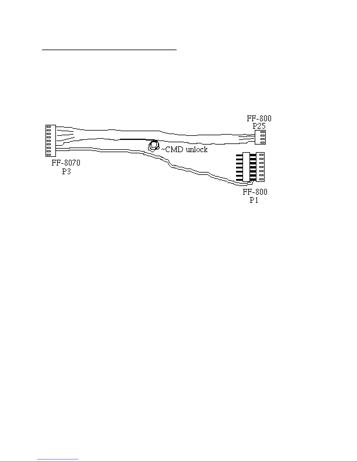
POWER/AUDIO Cable pictorial
The FF-8070 should be installed adjacent to the FF-800 (the P7 side). Install the DVR P3
connector and the FF-800 P25 connector. Remove the existing FF-800 P1 connector and install
the daisy chain connector from the DVR cable. Re-install the existing power connector on the top
of the DVR daisy chain connector.
The FF-8070 ~CMD unlock signal is provided as an unconnected wire that is coiled and secured
near the center of the power/audio cable. The end of this wire has a molex crimp pin installed with
a short section of heat shrink tubing to prevent it from shorting to adjacent circuitry. This wire can
either be connected to the FF-800 P5 connector (one of the logic outputs), to a user supplied
switch, or left as is (if no DVR security code is desired).
If the ~CMD unlock signal is connected to the FF-800 P5, use the associated logic output to allow
programming of the DVR security code. The FF-800 logic output commands should be placed in
sysop secure mode (see the FF-800 manual for details on configuring the FF-800 logic output
commands to require control unlock security).
If there are any connections to the FF-800 P7, remove the existing connection and install the
supplied ribbon cable. Move the existing P7 connection to the DVR P5a connection. The other
end of the DVR ribbon cable goes to FF-8070 P5.
Page 25

The battery backup cable provides a DB-9 connection for an external battery:
DB-9 pinout
1 BATT+ (8-12V)
2 n/c
3 n/c
4 n/c
5 n/c
6 BATT7 BATT8 BATT9 BATT-
 Loading...