

Ffeuk F3K User Manual
End To End
Optical Beam Smoke Detector
User Guide
EN
2
1.General Information
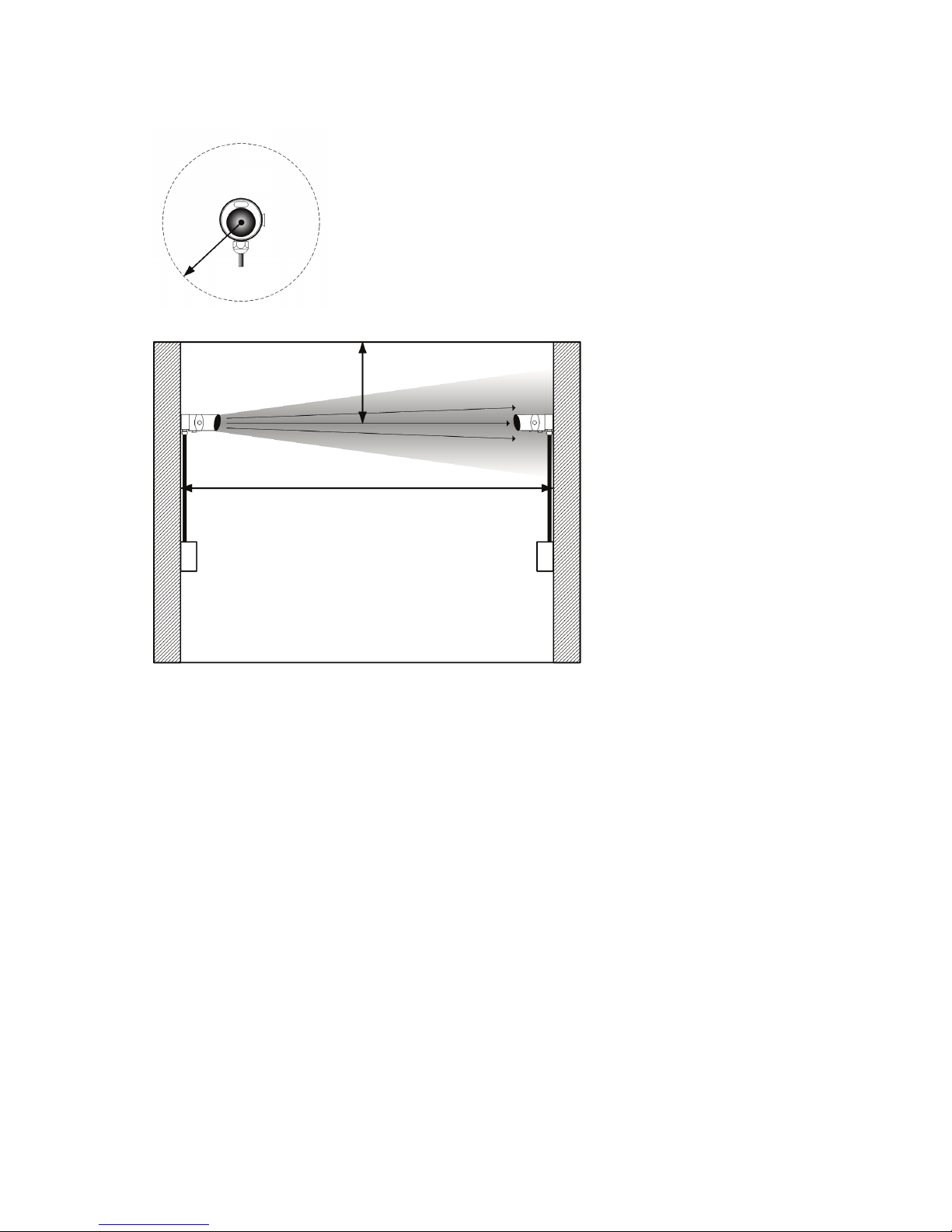
>30cm
>30cm
Transmitter
Receiver
Power
Supply Unit
Controller
5 - 120m
• IMPORTANT NOTE: The infrared beam path MUST be kept clear of obstructions at all
times! Failure to comply may result in the system initiating a Fire or Fault signal.
• All installations should comply with local regulations
• For installations approved to UL 268 refer to NFPA 72 for installation guidance. In such
installations, it is advised that the maximum distance of Transmitter and Receiver from the
ceiling must be 10% of the distance between floor and ceiling
• Ensure a clear line of sight from Receiver to Transmitter
• Mount on solid surfaces (structural wall or girder) and ensure fixing is rigid
• Position beam as high as possible, but with a minimum distance of 30cm from
Receiver/Transmitter to ceiling
• Mount Receiver and Transmitter directly opposite each other
• Do NOT position where personnel or objects can enter the beam path
• Do NOT install the Transmitter or Receiver in environments where condensation or icing are
likely to occur
Ensure clear line of
sight from Receiver
to Transmitter
3
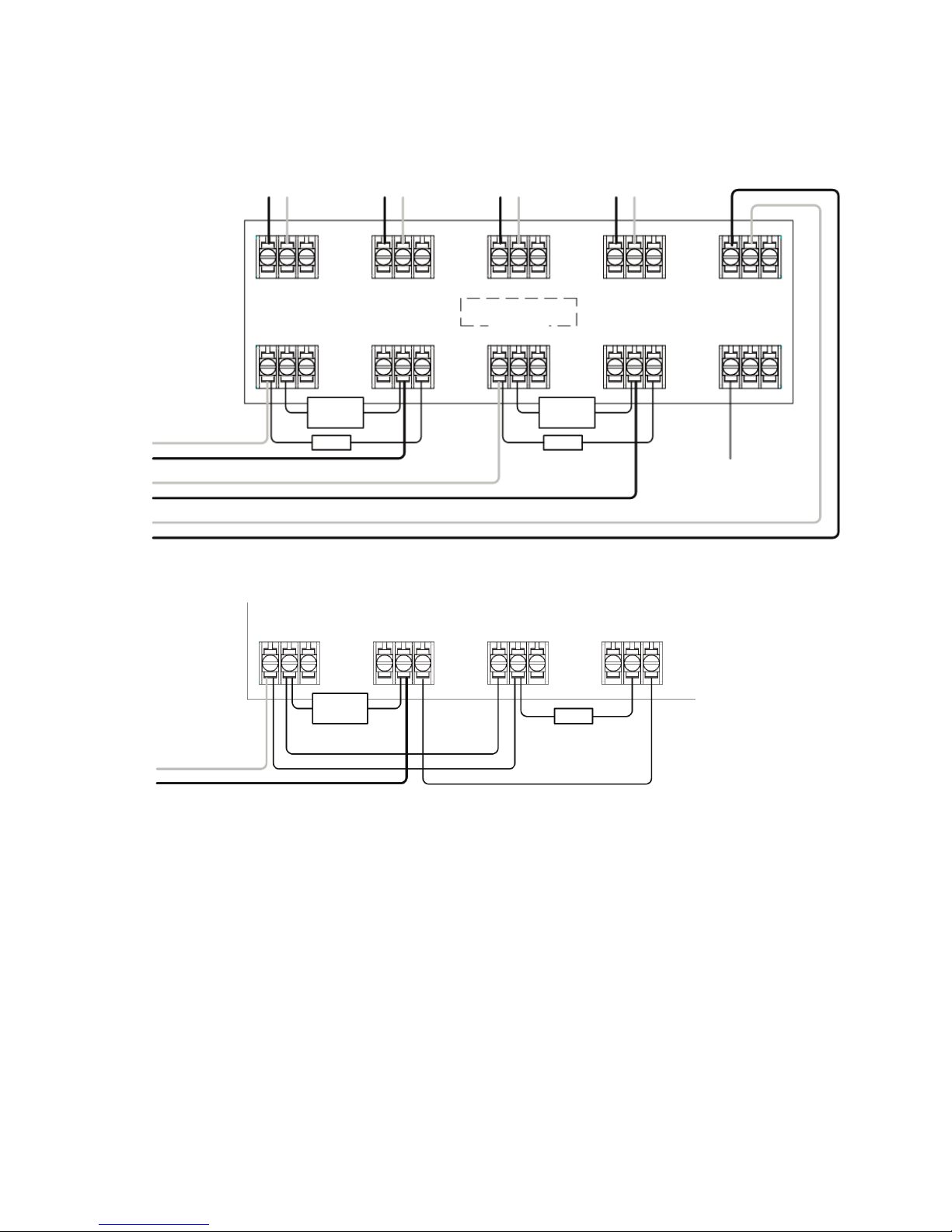
• Note 1: This component is the fire resistor. Its value is specified by the Fire Control Panel
manufacturer. For U.S. installations it is typically a short circuit
• ALWAYS use a separate 2-core cable for each Receiver head
• CAUTION: For system monitoring - Do not use looped wire under any terminals. Break wire
run to provide monitoring of connections
• Components not supplied:
• End Of Line ('EOL') component - supplied by Fire Control Panel manufacturer
• Fire Resistor
• After installation, check operation of Fire and Fault connection on Fire Panel
• Apply a voltage of 5V to 40V to ‘EXT RST’ contact for at least 2 seconds to clear a latched
fire condition
• For wiring to other types of Fire Control Panel, or to wire multiple Controllers onto one Zone,
refer to additional installation instructions supplied with the product
2. Wiring Diagrams
R
ECEIVER 1
OUTPUT
+
-
RECEIVER 2
O
UTPUT
+ -
TRANSMITTER
S
UPPLY
+ -
TRANSMITTER
S
UPPLY
+ -
12V to 36V DC
RECEIVER 1
F
IRE
N/O COM N/C
RECEIVER 1
F
AULT
N/O COM N/C
R
ECEIVER 2
FIRE
N
/O COM N/C
RECEIVER 2
F
AULT
N/O COM N/C
RECEIVER 1
FIRE
N/O COM N/C
RECEIVER 1
FAULT
N/O COM N/C
RECEIVER 2
FIRE
N/O COM N/C
RECEIVER 2
FAULT
N/O COM N/C
see note 1
see note 1
E
OL
EOL
see note 1
EOL
E
XTERNAL
R
ESET
E
XT
R
ST
ZONE 1 Z
ONE 1 +
ZONE 2 ZONE 2 +
SUPPLY S
UPPLY +
ZONE 1 ZONE 1 +
For connection of two Receivers to one zone:
Wiring two Receivers onto two zones:
4
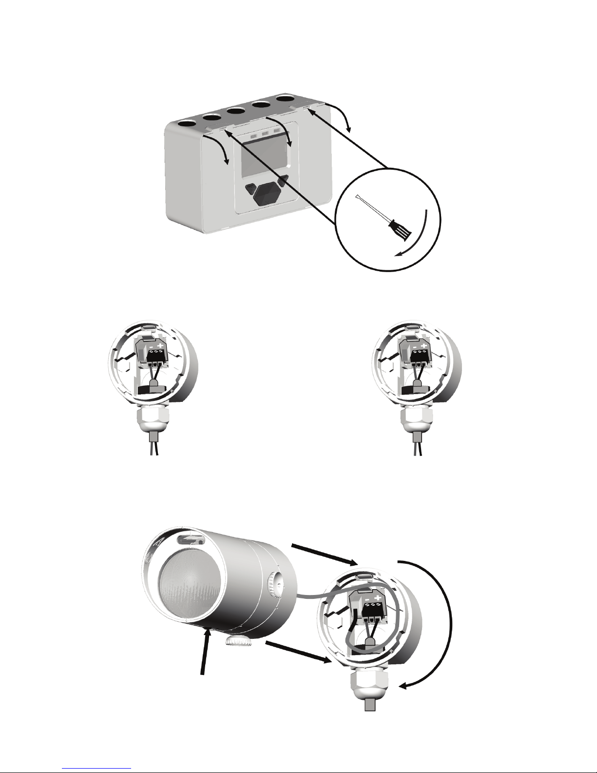
3. Fitting the Product
LED indicator must face
downward
- +
TO ‘RECEIVER
OUTPUT’ ON
CONTROLLER
BOARD
R
ECEIVER:
- +
TO
12 to 36V SUPPLY OR
‘TRANSMITTER SUPPLY’
ON CONTROLLER
BOARD
TRANSMITTER:
5
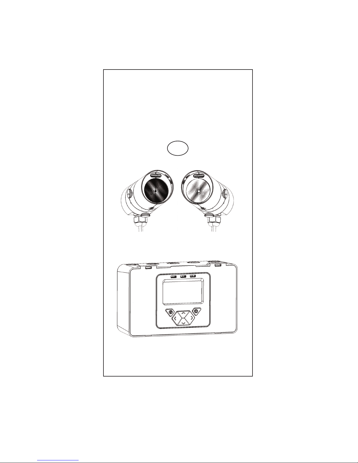
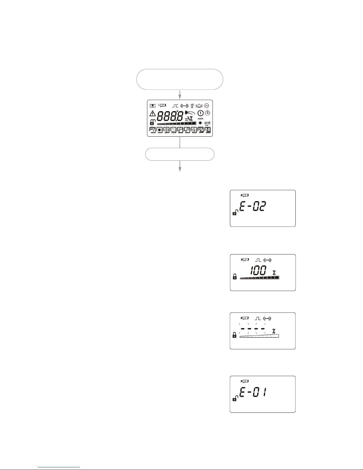
NOTE: One System Controller can be used to control and monitor up to two Receiver
heads. The ‘#’ symbol in this guide is used to represent the number of the Receiver
currently selected (1 or 2).
Apply Power to Controller,
Receiver(s) & Transmitter
4. Apply Power
• Commissioned System:
• Communications fault, or no Receiver connected:
• Receivers are not found (normal at this stage):
• Receivers have been found but not commissioned:
3 seconds
 Loading...