

Ffeuk 3171MR, 3171S Installation And Operating Manual
Weatherproof Vibration Switch
Types 3171MR and 3171S
Installation and Operating
Manual
EN
1. Introduction
The type 3171 is a low-cost, vibration-sensitive, safety switch for the protection of rotating and
reciprocating machinery. It is adjusted to operate above the machine's normal running levels of
vibration, activating machine shut-down circuits and/or alarms and to switch off the machine
before catastrophic failure.
The switch detects vibration in all directions. Unbalanced forces created by failing machinery
contain both the fundamental frequency and harmonics. The switch responds by shutting off the
machine if any components of vibration exceed the set value.
The switch operates as follows:
• Mounted vertically on a vibrating machine, a steel ball is held by a permanent magnet into
a conical seat
• If the vibration of the machine is sufficient to cause the ball to detach from the magnetic
field of the magnet, it trips a latched lever, thus releasing a micro switch plunger so the
machine can be stopped
• In type 3171MR, the ball and lever are latched by pressing the reset button manually
• In type 3171S, the ball and lever are latched by actuating a solenoid remotely, using an
electrical signal or by pressing the reset button manually
• The SET LEVEL of the vibration switch is set by adjusting the gap between permanent
magnet and ball.
Consult the FFE website at www.ffeuk.com for the latest information on applications and any
new warnings that may affect installation or safety.

2
2. Warnings and Cautions
Read all Warnings and Cautions before Installation and Set-up.
2.1 Warnings
2.2 Cautions
WARNING !
• Risk of electric shock
3. Mechanical Installation
3.1 Introduction
The following tools will be needed:
• 3mm hexagon key for lid screws
• 4mm hexagon key to adjust SET LEVEL
• Wire strippers and wire cutters
• 3mm flat blade torque screwdriver for terminal block electrical connections
• 5mm flat blade torque screwdriver for internal protective earth terminal
• Adjustable spanner to fit cable gland
• For electrical safety, the vibration switch must be earthed
• For your own safety, disconnect all electrical power to the vibrating machine and ensure the
vibrating machine cannot operate during installation. Follow all safety warnings of the
machine manufacturer
• For 3171S models, if the solenoid circuit is powered from a separate supply that is not
automatically disconnected by the machine isolation device, then regulations require that
the solenoid supply have its own isolation device and also must be identified both at the
isolation device and vibration switch. The solenoid supply must be fused at a maximum of
5A.
• Installation of the vibration switch shall only be carried out by qualified personnel
• Remove vibration switch from carton
• Vibration switch is factory set to 3 g, unless a preset switch has been ordered
• To reduce the risk of damaging internal components and wiring, installation and wiring must
be performed within a temperature range of -10°C to +50°C
• Do not allow moisture or other airborne contaminants inside the switch as they can cause
corrosion
• When closing the lid, ensure the seal is not lost or damaged.
• To avoid corrosion inside the vibration switch keep enclosure sealed before and after
installation
• The Cable Entry Cap is for transport and storage and is not suitable for resisting ingress of
moisture if a vibration switch is installed in the field and not wired. Unless the switch is
immediately wired using a suitable cable gland, replace the Cable Entry Cap with Blanking
Plug 0051-002-01 (see accessories).
3
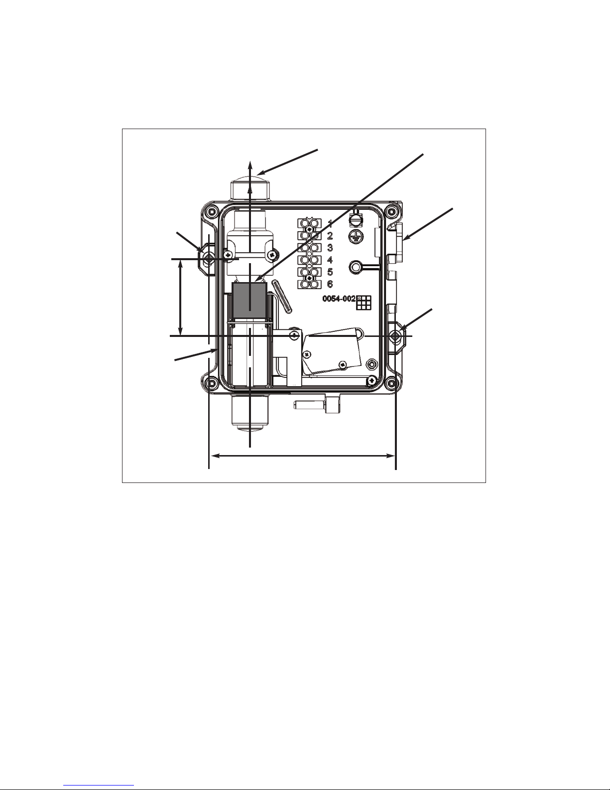
3.2 Mechanical Installation Details
The vibration switch must be fitted on the machine structure so that good transmission is
ensured from the likely source of excess vibration.
The vibration switch shall be firmly fixed in the vertical orientation shown in figure 1 to a vertical
surface of the vibrating machine using M5 fixings suitably resistant to vibration.
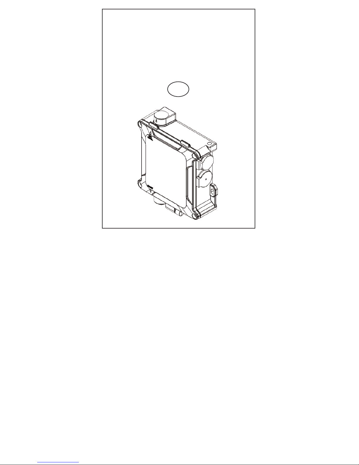
Figure 1: Mechanical installation to the surface of the vibrating machine
VERTICAL
124
51
Set Level Cap
Transport
Plug
M5 fixings
in the two
places
M5 fixings
in the two
places
Cable
Entry
Cap
Switch
Rating
Label
4. Electrical Installation
4.1 Introduction
• Do not exceed the switch contact ratings. The primary switching circuit is rated at 5 Amp
maximum and must be fused appropriately in line with the protected machine’s mains
supply and isolation device
• The DC-operated solenoid has a duty cycle of 25%. It is advised that a time limiter or
mono-stable device be fitted in line to automatically disconnect the solenoid supply after 30
seconds
• When connection is by a cord, the Earth wire connection must be longer than the Live and
Neutral wires, such that failure of the strain relief will cause the Earth wire to be the last
conductor interrupted
• To prevent water running down onto the vibration switch, add a ‘drip loop’ in any external
cabling
• For ambient temperatures below –10°C, use external wiring rated for the minimum ambient
temperature expected
 Loading...