

Page 1
FFES
Service: +48 888-777-053
Office: +48 796-149-338
e-mail: [email protected]
www.ffes.pl/en
Instruction manual
ZXX
Page 2

FFES- FABRYCKI FUTURE ELECTRONIC SOLUTIONS 2016
2
Contents
1. Overview ......................................................................................................................... 3
1.1 Application ................................................................................................................ 4
1.2 Technical data ........................................................................................................... 4
2. Control panel operation ................................................................................................... 5
2.1 Profile choice ............................................................................................................. 6
2.2 Session temperature ................................................................................................. 6
2.3 Session time .............................................................................................................. 6
2.4 Power of vaporizer .................................................................................................... 7
2.5 Aromatherapy ........................................................................................................... 7
2.6 Ventilation ................................................................................................................. 7
2.7 Operation mode ........................................................................................................ 8
2.8 Menu ......................................................................................................................... 8
2.8.1 Light .................................................................................................................... 8
2.8.2 Timer ................................................................................................................... 9
2.8.3 Delay ................................................................................................................... 9
2.8.3 Hysteresis ............................................................................................................ 9
2.8.5 AUX ..................................................................................................................... 9
2.8.6 Language ........................................................................................................... 10
2.9 Musicotherapy ......................................................................................................... 10
2.10 Remote control ........................................................................................................ 10
2.11 Smart home ............................................................................................................. 10
2.12 Service mode ........................................................................................................... 11
2.13 Troubleshooting ...................................................................................................... 11
3. Installation of the controller .......................................................................................... 12
3.1 Block diagram .......................................................................................................... 13
3.2 Electrical diagram .................................................................................................... 14
4. Terms of warranty ......................................................................................................... 19
Page 3
FFES- FABRYCKI FUTURE ELECTRONIC SOLUTIONS 2016
3
1. Overview
This manual is intended to familiarize the user with the operation and installation of the
controller. The third chapter is solely dedicated to authorized persons with electrical
qualifications. The controller should only be used by an adult. In case of failure to comply
with the manual rules and instructions, the product is no longer covered by the warranty.
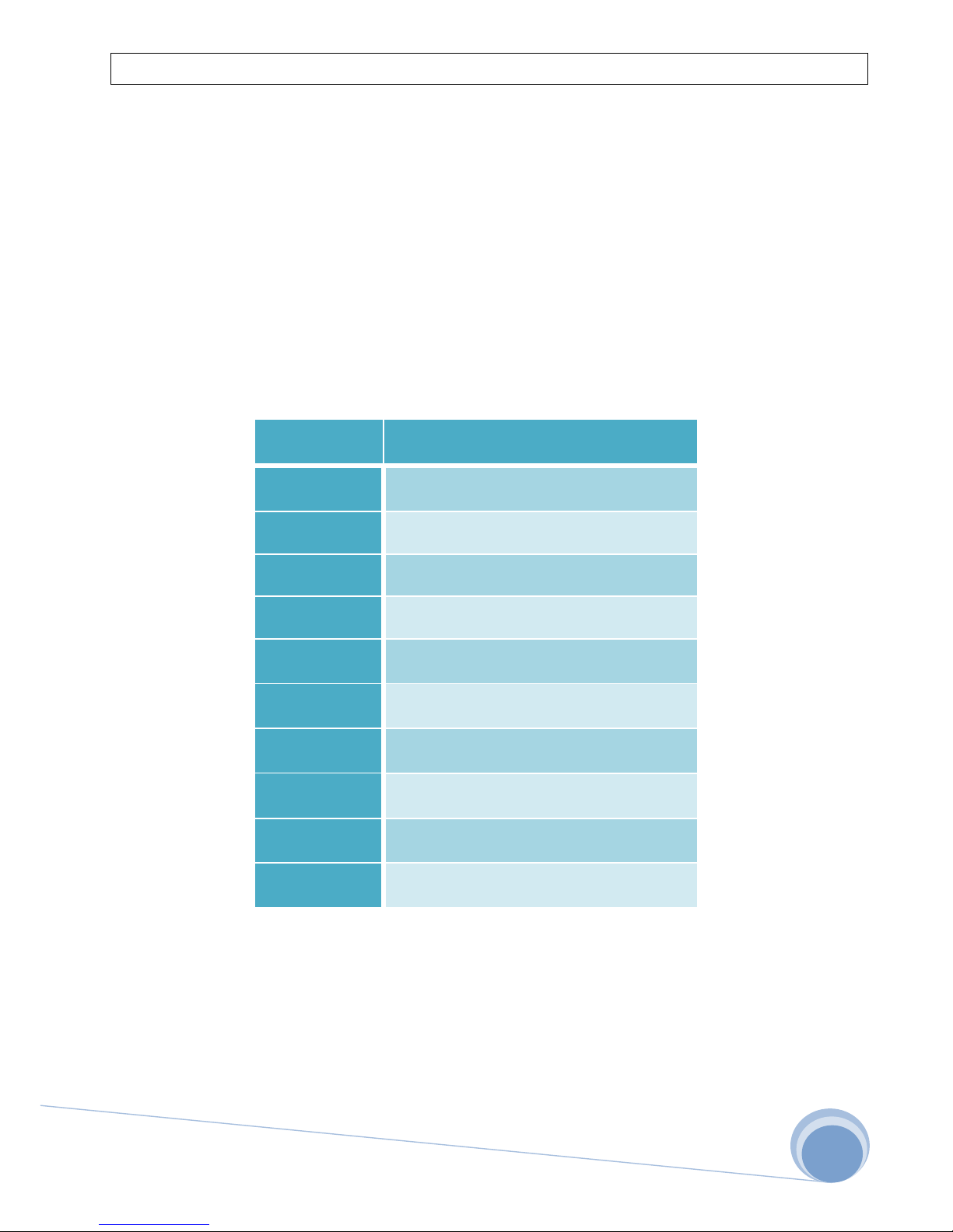
This user manual is universal for the entire series of ZXX controllers, whose explanation is
shown in the table below.
ZXX
Model
Explanation
Z00
Steam room
Z01/Z10
Heater/IR: 9KW
Z11
Heater: 9KW + IR: 5KW
Z02/Z20
Heater/IR: 15KW
Z12
Heater: 15KW + IR: 5KW
Z22
Heater: 15KW + IR: 9KW
Z03/Z30
Heater/IR: 22KW
Z13
Heater: 22KW + IR: 9KW
Z04/Z40
Heater/IR: 30KW
Z24
Heater: 30KW + IR: 15KW
Versions ZXXP support Combi heaters with a vaporizer of power 3KW or 5KW.
Versions ZXXB support audio system
Versions ZXXW support remote control
Page 4
FFES- FABRYCKI FUTURE ELECTRONIC SOLUTIONS 2016
4
1.1 Application
FESS ZXX controller is a Polish product, designed to control the operation of the IR, dry,
wet saunas and a steam bath. It is powered by three-phase voltage, and in the case of
steam and small IR saunas by single-phase voltage. The controller monitors and controls the
devices such as a heater, vaporizer, infrared panels, steam generator, fan, light, and
aromatherapy dispenser. The work of these devices depends on the settings that the user
enters, and on the temperature measurement.
1.2 Technical data
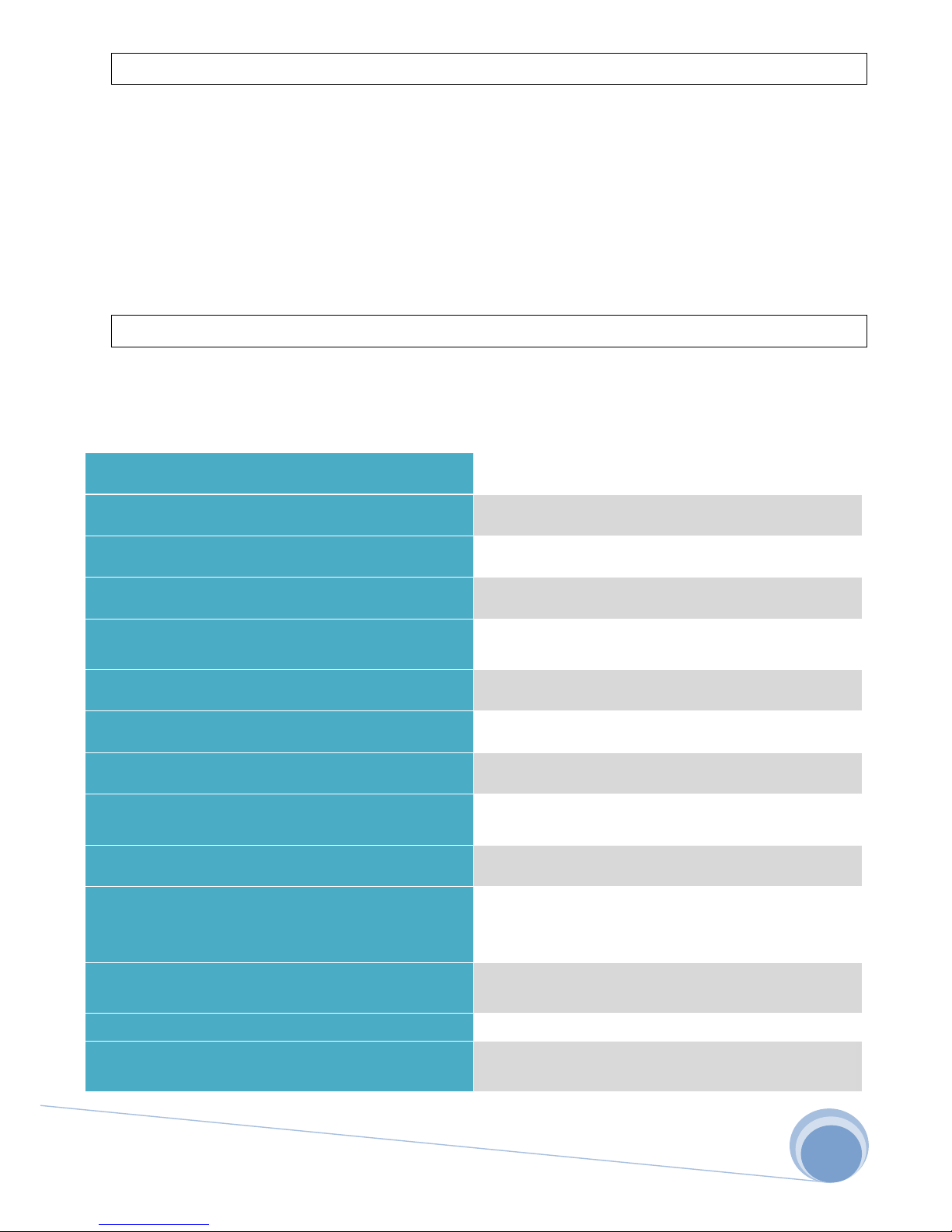
The controller is a set of components consisting of the main unit, control panel and a
temperature sensor. The technical data is shown in the table below.
Supply Voltage
3N~ 400V/50HZ or 1N~ 230V/50Hz
Power consumption module+panels+sensor
5W
Maximum load for the periphery
3x100W
Operating temperature of module, panel
0 -60oC
Set temperature
Baths 20-50 oC IR 30-60oC Heater 30-110oC
Combi heater 30-65 oC
Set operation time
1min-20h
Delay time
1min-24h
Temperature measurement range
0-127oC
Thermal protection
Heater: +125oC IR/Baths/Combi: +80 oC
Thermal fuse: 140 oC
Hysteresis
1-6oC
Dimensions of the main module
Ingress Protection Rating
9KW/15KW: 248 x 198 x 116mm
22KW/30KW: 348 x 228 x 166mm
IP65
Dimensions of the control panel
Ingress Protection Rating
166 x 114 x 33mm
IP40
Dimensions of the temperature sensor
50 x 40 x 28mm
Audio
Class D Amplifier 2x10W RMS 8Ω
Bluetooth 3.0
Page 5

FFES- FABRYCKI FUTURE ELECTRONIC SOLUTIONS 2016
5
2. Control panel operation
The panel is made of tempered glass and a metallic cover. It is operated by five touch
buttons and a two-line alphanumeric OLED display. To activate the controller, button ON
should be pressed for about 2 seconds, to turn it off do the same with button OFF. After
exiting the standby mode, a start-up screen will open, and next a window with profile
selection. The steps are described in the following sections.
Increasing
Next the value
Accept
Turn on
Enter the menu EXIT
Exit the menu Stop operation
Turn off
Decreasing
the value
Page 6
FFES- FABRYCKI FUTURE ELECTRONIC SOLUTIONS 2016
6
2.1 Profile choice
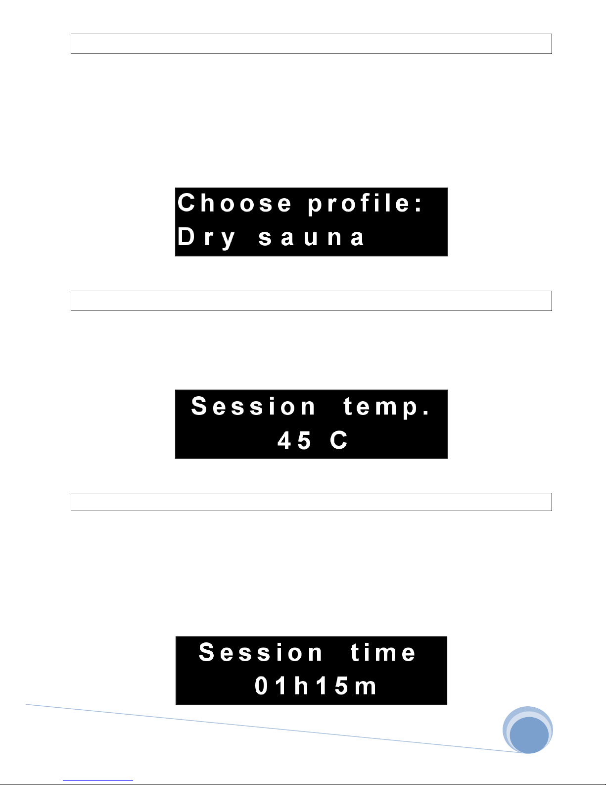
The first step to start the session is to choose a profile. Depending on the controller
model there is a choice of a steam bath, dry sauna, infrared sauna, wet sauna and a
ventilation profile. After selecting a dry sauna, depending on the temperature and time, the
heater will be turned on/off, with IR sauna infrared heaters, and for steam bath a steam
generator. For ventilation, operation time of the fan can be determined.
2.2 Session temperature
The next step is to determine the temperature. In the case of dry sauna it may be 30110oC , for steam bath 20-50 oC, wet sauna 30-65 oC, and for IR sauna 30-60oC .
2.3 Session time
The next step, sets operation time of the sauna session, it is counted from the moment
in which the heater, steam generators or infrared heater are started. First, you have to set
the number of hours, after pressing OK button, determine the number of minutes. When
determining the time, keep in mind the sauna’s heat-up time. Session time can be a
maximum of 20 hours.
Page 7
FFES- FABRYCKI FUTURE ELECTRONIC SOLUTIONS 2016
7
2.4 Power of vaporizer
This stage is available only for the sauna with a combi heater. At this stage, power of
vaporizer is determined. Power of vaporizer is the percentage of the vaporizer’s time cycle,
which lasts for 2 minutes.
Example: The set value is 10%, in this case the vaporizer runs for 12 seconds. And for the
remaining time of 108 seconds it will be turned off. This cycle takes place in a loop that ends
with the end of the session.
2.5 Aromatherapy
The course of this step is analogous to the one above with the addition of cycle
regulation of aromatherapy dispenser. The dispenser cycle may be within the range
from 1 to 10 minutes, an adjustment is made through the MENU.
2.6 Ventilation
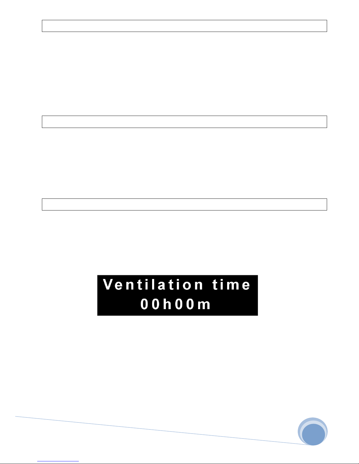
The final step in the transition into operation mode is to provide time of ventilation,
which will be launched after finished session. When you touch the button to increase the
value, minutes also change, and after reaching 59 minutes also hours. Ventilation time
cannot be longer than 2 hours. When choosing 00:00, ventilation will not start.
For wet sauna, auto drying mode is available, in which after finished session, the heater
is activated for 15 minutes at the set temperature of 75 ° C. The user at this stage can select
it or abandon it.
Page 8
FFES- FABRYCKI FUTURE ELECTRONIC SOLUTIONS 2016
8
2.7 Operation mode
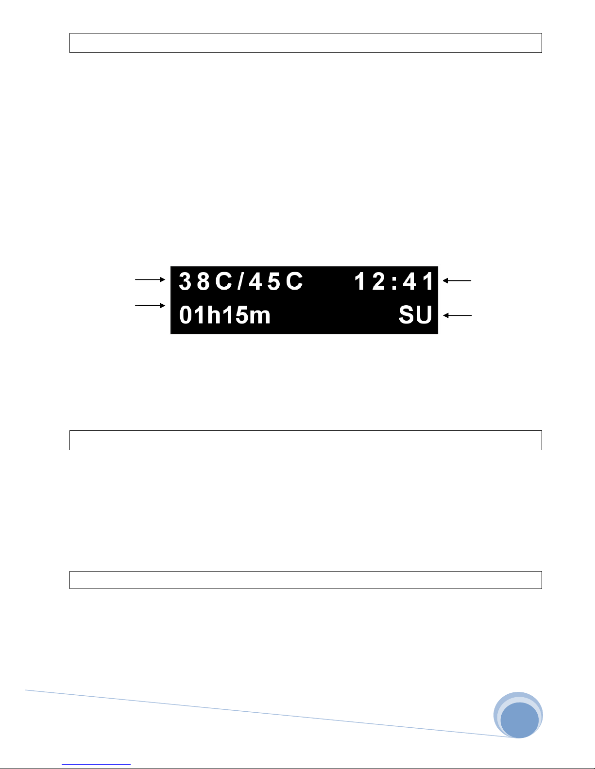
The transition to operation mode switches on the heater, the steam generator or
infrared heaters. After reaching the set temperature, the heater is turned off when the
temperature falls by the hysteresis value, the device is switched on again. In this mode, the
controller controls the temperature, counting down the time set by the user, making sure
that the temperature in the sauna does not exceed the allowable temperature. It also
controls the status of the water level in the case of Combi heater, and displays the current
time. Additionally, in this mode, when you touch the up arrow, you can turn on or off light.
Current/Set
Temperature Current time
Time left to the Profile
end of session
DS- Dry sauna
IR- IR sauna
WS- Wet sauna
SR- Steamroom
2.8 Menu
The menu may be accessed from each level by touching the MENU button, to exit you
should use the MENU or STOP button. In the Menu mode, you can set the current time, the
delay with which the sauna is to start up, turn on / off the lights connected to the main
unit, adjust the value of hysteresis.
2.8.1 Light
The LIGHT option is defined as lighting condition, which may have the value YES which
means the light is on, or NO- the light is off . State lighting is signaled on the display in
operating mode. After turning off the controller, lighting is automatically switched off. The
maximum bulb value may be 100W.
Page 9
FFES- FABRYCKI FUTURE ELECTRONIC SOLUTIONS 2016
9
2.8.2 Timer
After going to timer setting, i.e. a clock, first you can set an hour. After you touch the OK
button, it is accepted, and then you can set minutes. The clock is displayed in a 24-hour
format. After losing power, the clock is reset and returns to 00:00.
2.8.3 Delay
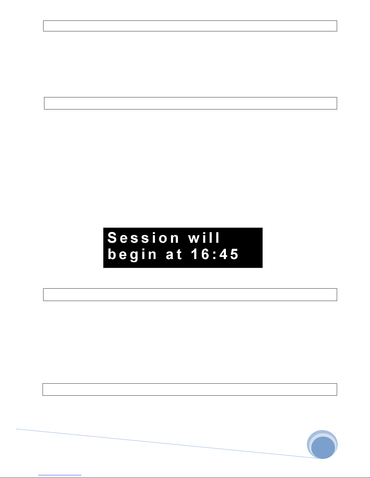
The controller is equipped with a delay function, which allows you to activate the sauna
at a specified time and with the parameters set by the user. Similarly as in a timer, the
number of hours is first set after which the sauna is going to activate, and then the minutes.
In the next steps, a profile is selected, as well as session temperature, session time and
possible ventilation time, and power of the dispenser. After finishing this step, the
controller calculates the time for the sauna to activate, and presents it on the display, and
then it switches off. Starting the driver again, or interrupting the above mentioned process,
resets the delay time.
2.8.3 Hysteresis
Hysteresis is an adjustable parameter, can range from 1-6 °C. This parameter determines
the drop in temperature at which the heat device turns on again.
Example: The set temperature is 90 °C, after reaching this temperature the heater in the
sauna switches off. For a hysteresis of 3 °C, it will turn on again at a temperature of 87 °C.
2.8.5 AUX
When the sauna is not equipped with a fan, this parameter can set the status of an
additional device connected to the main unit in place of the fan.
Page 10
FFES- FABRYCKI FUTURE ELECTRONIC SOLUTIONS 2016
10
2.8.6 Language
The controller supports Polish, English and German language, which can be changed at
any time.
2.9 Musicotherapy
In versions ZXXB, the controller is equipped with a Bluetooth module supports A2DP.
So devices supporting this technology are able to work with the controller and play music
on the speakers mounted in the sauna. For establish communication, you must exit standby
mode. After entering standby mode communication is broken, it is impossible to establish
the connection. The source device first step is the launch of BT, then connect to the "FFES
AUDIO" and start your playlist. After that the devices are paired, if you change the source
device, the process must be repeated. The status of the connection is indicated on the
display in the work mode.
Password: 1234 for devices with Bluetooth 2.1 and lower
2.10 Remote control
Each controller FFES ZXX purchased after 10.09.2016r. is equipped with an additional
slot for the Wi-Fi module "ZXXW." This module acts as the access point to which you can
connect one device. Control of sauna is done using the "FFES Sauna" application, available
in the Google Play store. To start the control of the sauna, in the device with android
system , need to run your Wi-Fi card and connect to the network "FFES Sauna." The
application is a reflection of the control panel with limited service mode.
2.11 Smart home
Controllers FFES version of "Smart home" work with intelligent home systems. This
feature is available for all series ZXX without models for wet saunas, allows for the start of
the last selected program.
For to adapt functions, use potential free contacts smart home controller. One of the
terminals should be connected to the "PC" controller FFES, the second contact to the
neutral mains.
Contact closure starts the last set program, but their opening causing the transition to
standby mode.
Page 11
FFES- FABRYCKI FUTURE ELECTRONIC SOLUTIONS 2016
11
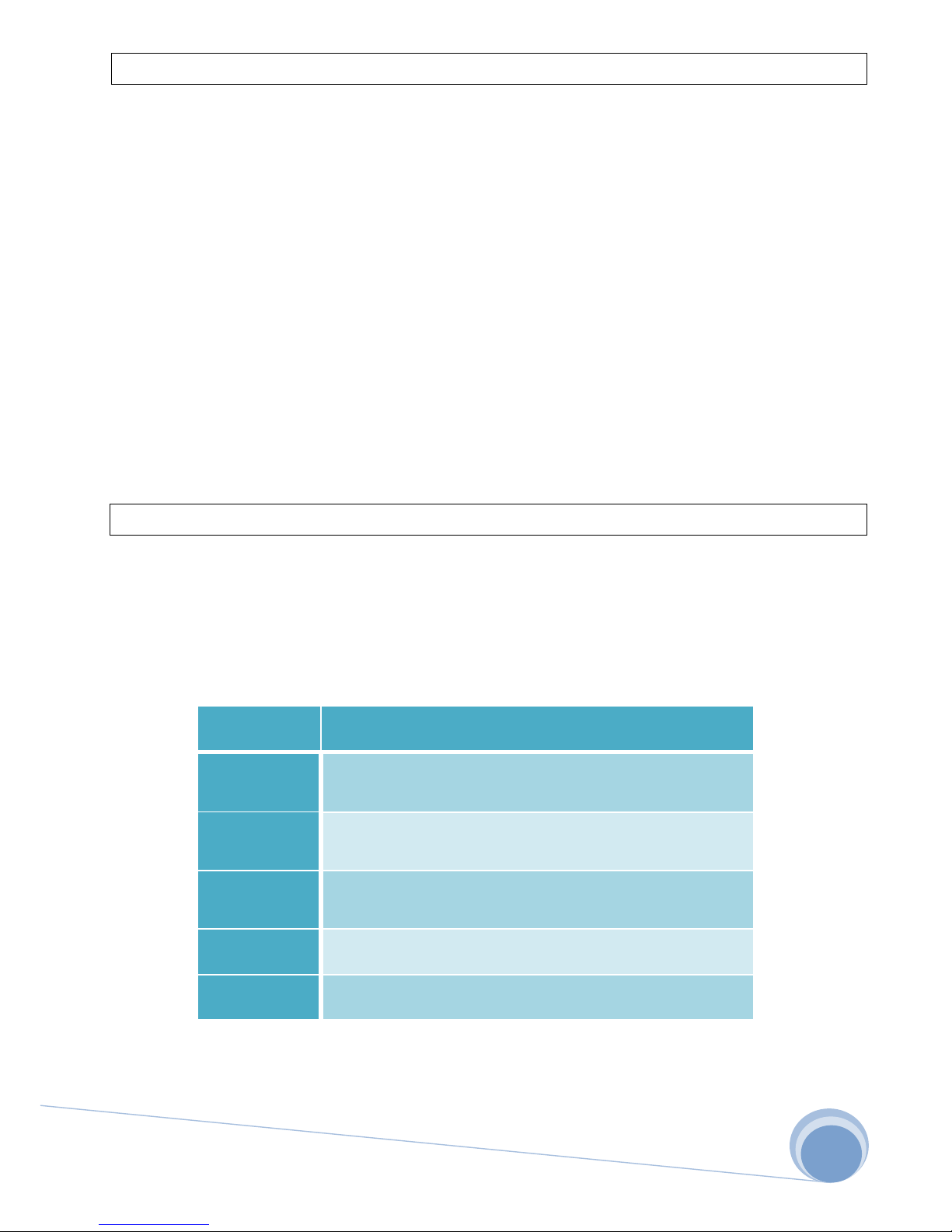
2.12 Service mode
The service mode provides additional features in the menu, that is:
- Adjusting the water sensor, detection of low potential at zero (Zero), for phase (Phase).
- Turning on/off aromatherapy function
- Turning on/off ventilation profile
- Changing the time cycle of the aromatherapy dispenser
- Establishing operation time of the vaporizer at the start of the session for wet sauna.
Deactivation or activation of the service mode is done by touching the MENU button
for 5 seconds in a standby mode.
2.13 Troubleshooting
In order to provide proper function and to ensure safety for sauna users, the controller
is equipped with an emergency mode. If an error occurs, please contact your sauna
supplier, or manufacturer of the controller. Any repairs should be performed by individuals
authorized to do so.
Error code
Description
01
Not plugged in / faulty temperature
sensor or thermal fuse
02
Over temperature of 125 ° C
or 80 ° C for wet / IR / Baths
03
Incorrect reading of the temperature
sensor
04
The rapid rise in temperature
05
Low water level in the heater tank
The controller has a wide range of protection against overvoltage, short-circuit, including
thermal protection causing disconnection of the heating equipment, and even complete
disconnection of power supply. Power cut occurs after 2 minutes of error 01 or 02.
Page 12
FFES- FABRYCKI FUTURE ELECTRONIC SOLUTIONS 2016
12
3. Installation of the controller
Installation of the controller can be performed only by persons with electrical
qualifications. Before installation, check the power of electrical installation, it should be
larger than the power of the heater. You should also equip yourself with appropriate fuses
and a switch to cut off the main power supply. In order to increase safety, a shunt release
should also be used and connected according to the diagram. To connect components,
cables must be used in an insulation resistant to temperatures of 150 °C, as well as crosssections shown in the table below. When installing the panels, a hole should be cut out
measuring 144.5 mm x 92mm. The temperature sensor should be mounted above the
heater, 15 cm from the sauna’s ceiling.
For models with Bluetooth or Wifi Do not use aluminum foil in the range of at least
30cm around the main module.
WARNING!
1. Do not place the temperature sensor wires close to power wires.
2. UTP cable should be used when temperature sensor wires over 10 meters.
3. Do not place the control panel wires close to power wires.
4. Do not install the control panel in the wall at which the heater is placed, if necessary
you should isolate THIS PART.
5. Be careful of rear part of the glass, the layer of paint is not resistant to scratches.
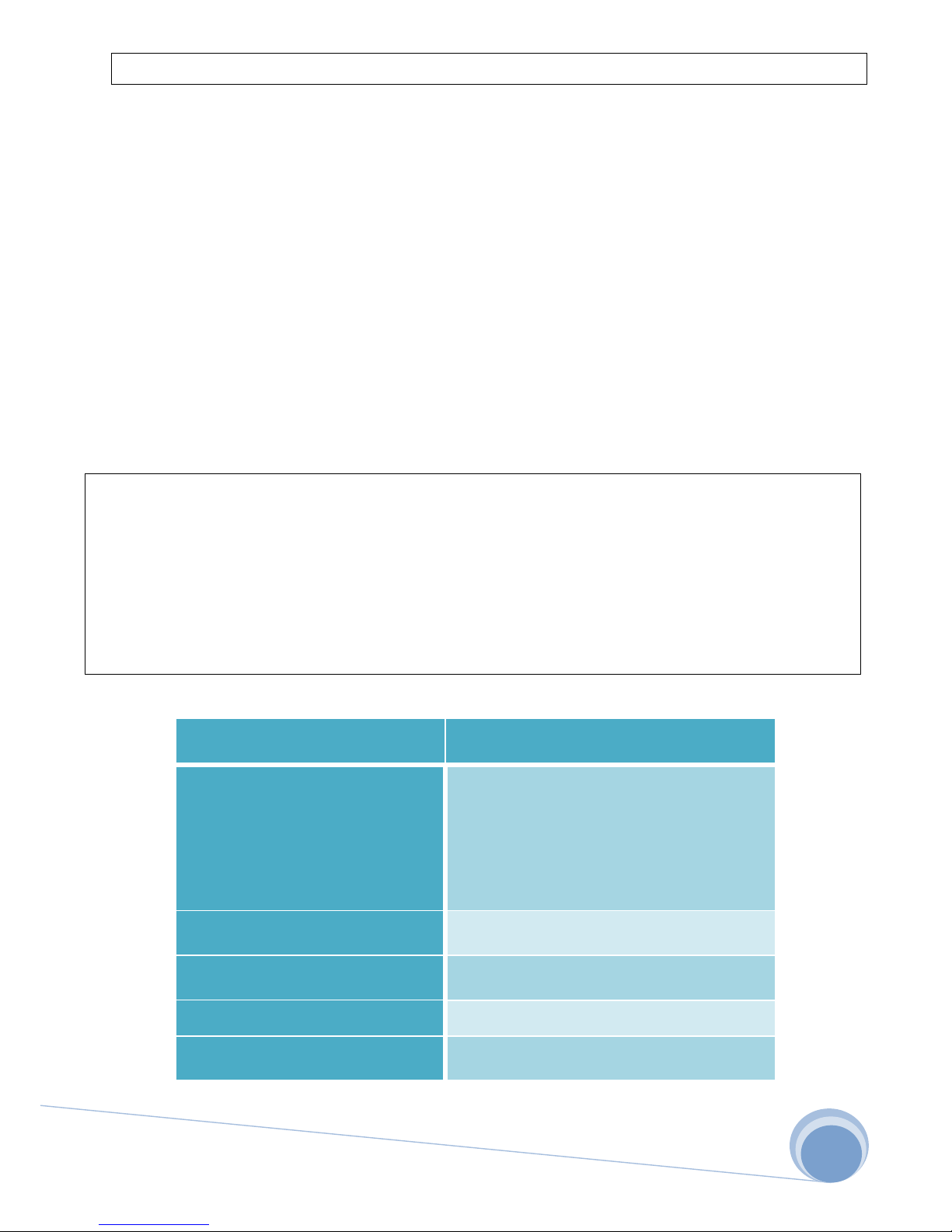
Subassembly
Cable cross sections / cable length
Power/Heater/IR
To 3KW-3x2.5mm2/20m
To 9KW-5x2.5mm2/20m
To 15KW-5x4mm2/20m
To 22KW-5x6mm2/20m
To 30KW-5x10mm2/20m
Control panel
4x0,25mm2/50m(UTP)
Temperature sensor
3x0,25mm2/50m
Periphery
3x1mm2/50m
Speakers
4x1mm2/5m
Page 13
FFES- FABRYCKI FUTURE ELECTRONIC SOLUTIONS 2016
13
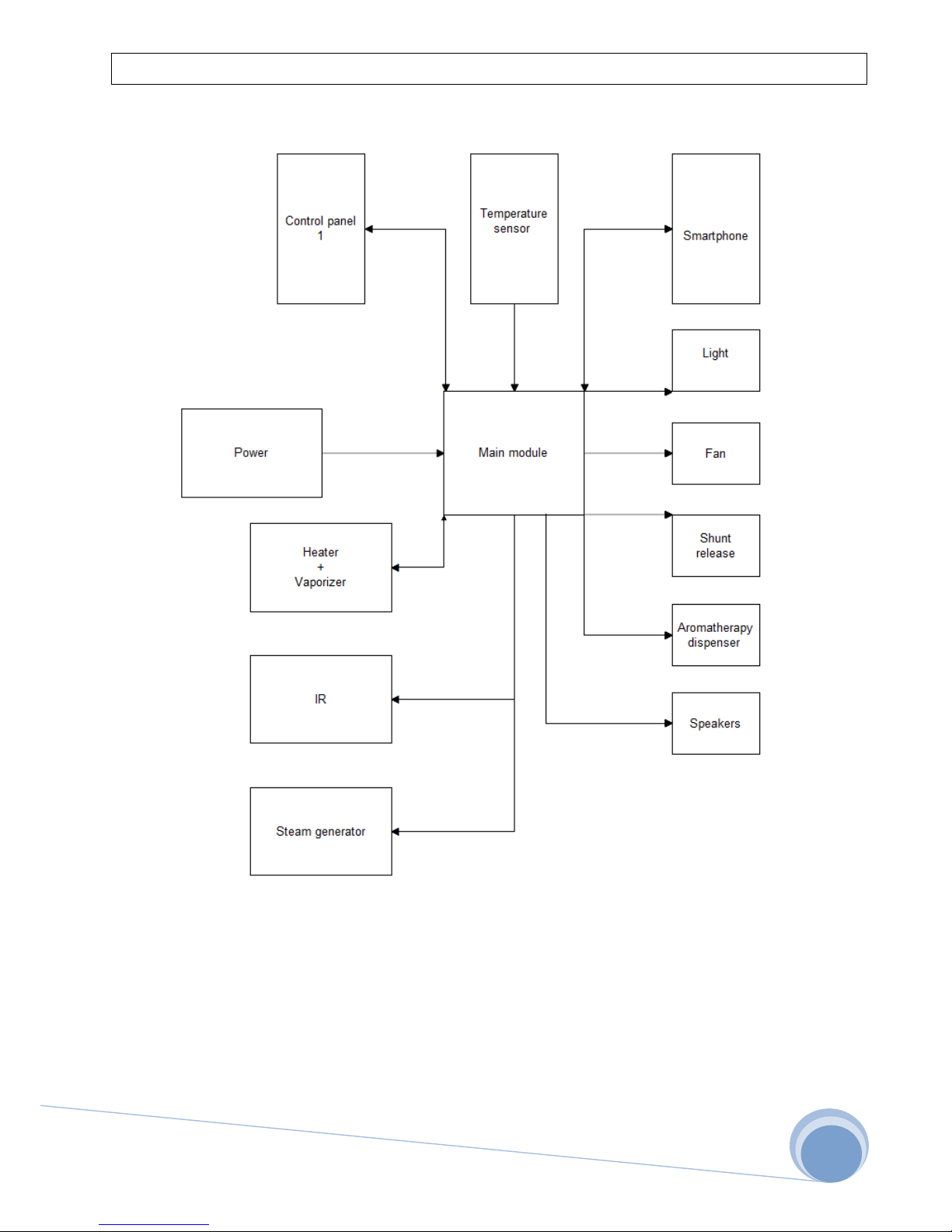
3.1 Block diagram
Page 14
FFES- FABRYCKI FUTURE ELECTRONIC SOLUTIONS 2016
14
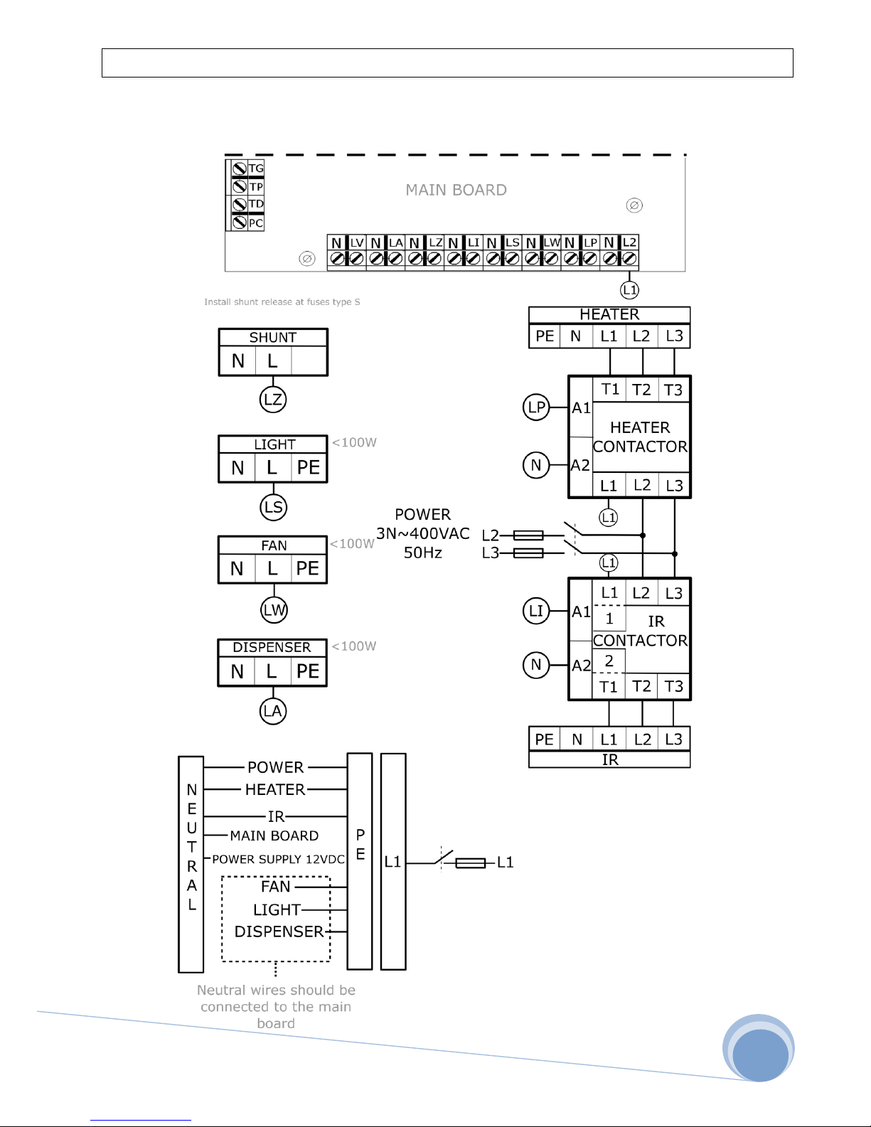
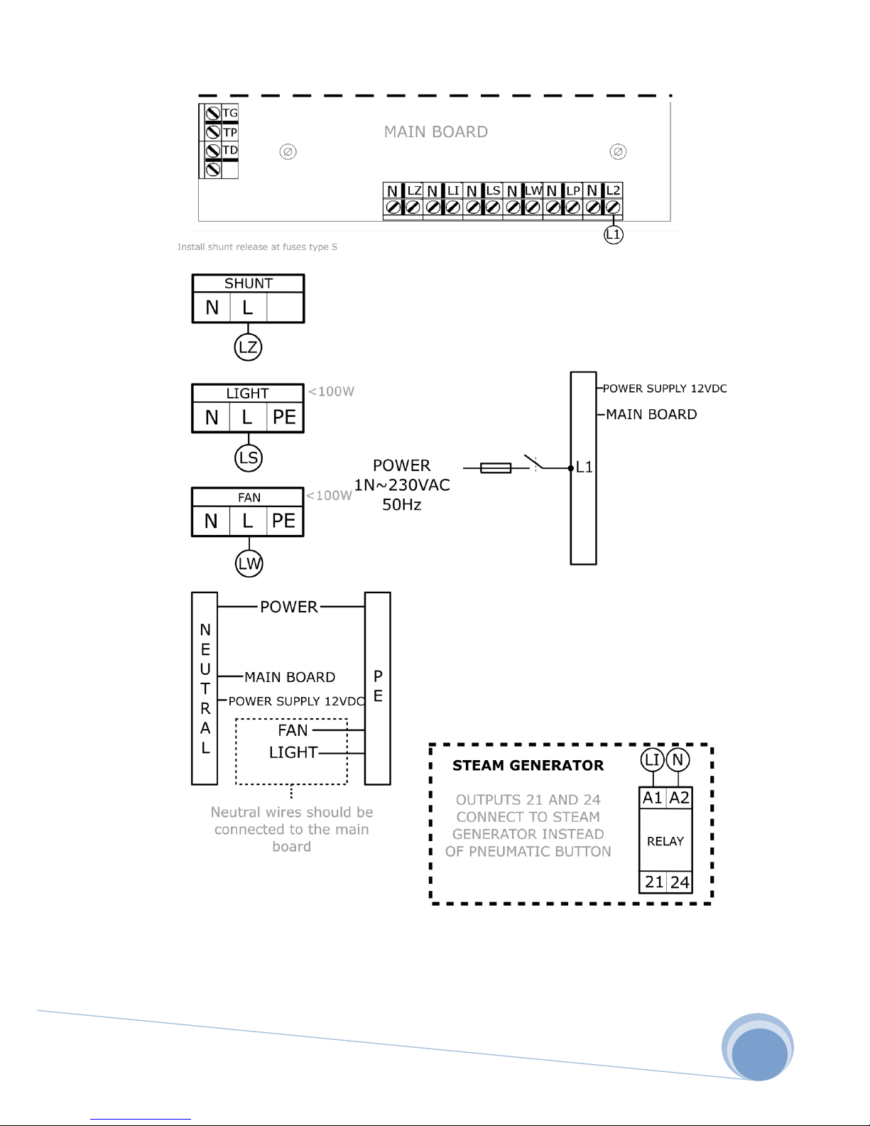
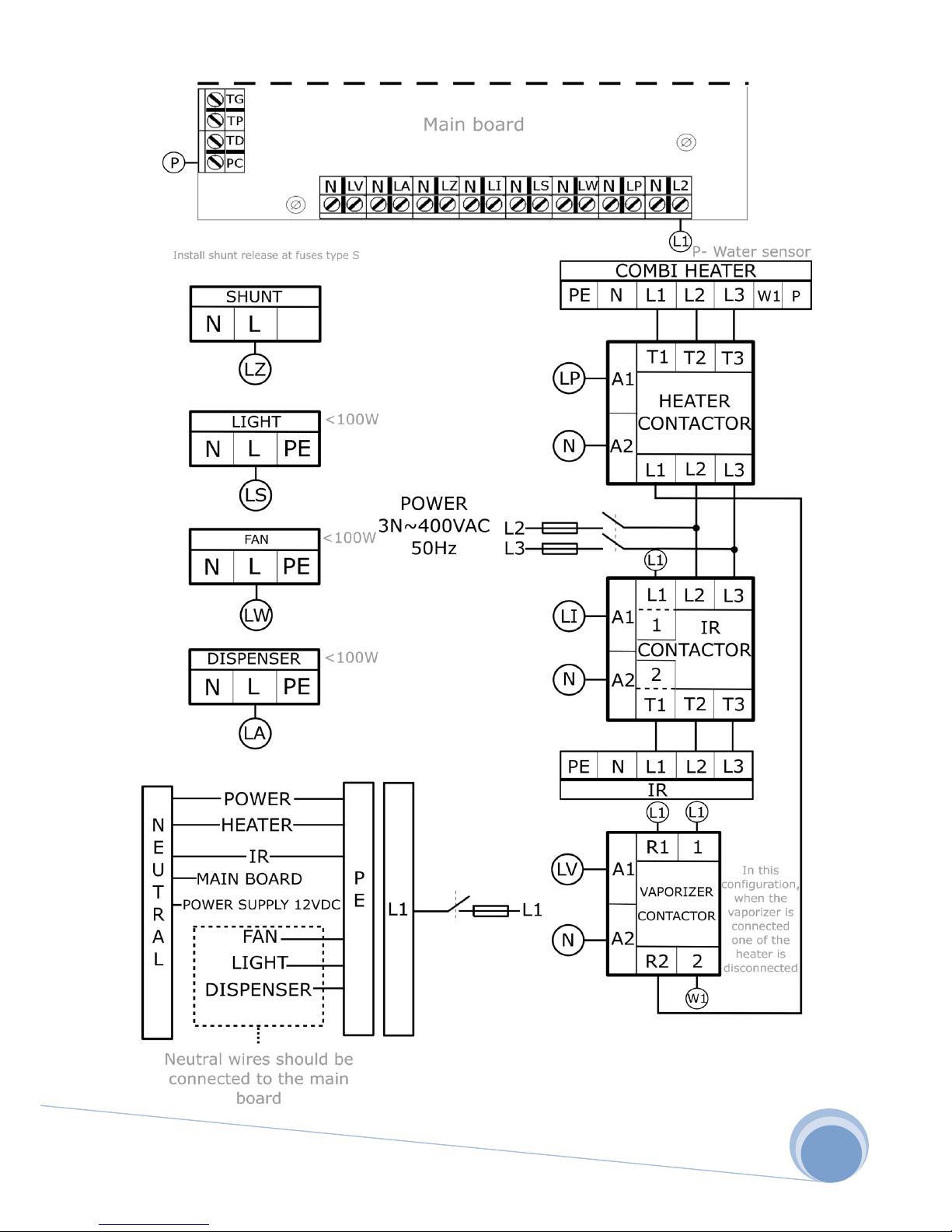
3.2 Electrical diagram
IR/Dry/MIX
Page 15
FFES- FABRYCKI FUTURE ELECTRONIC SOLUTIONS 2016
15
Steam room
Page 16
FFES- FABRYCKI FUTURE ELECTRONIC SOLUTIONS 2016
16
Wet/Wet+Dry+IR
Page 17
FFES- FABRYCKI FUTURE ELECTRONIC SOLUTIONS 2016
17
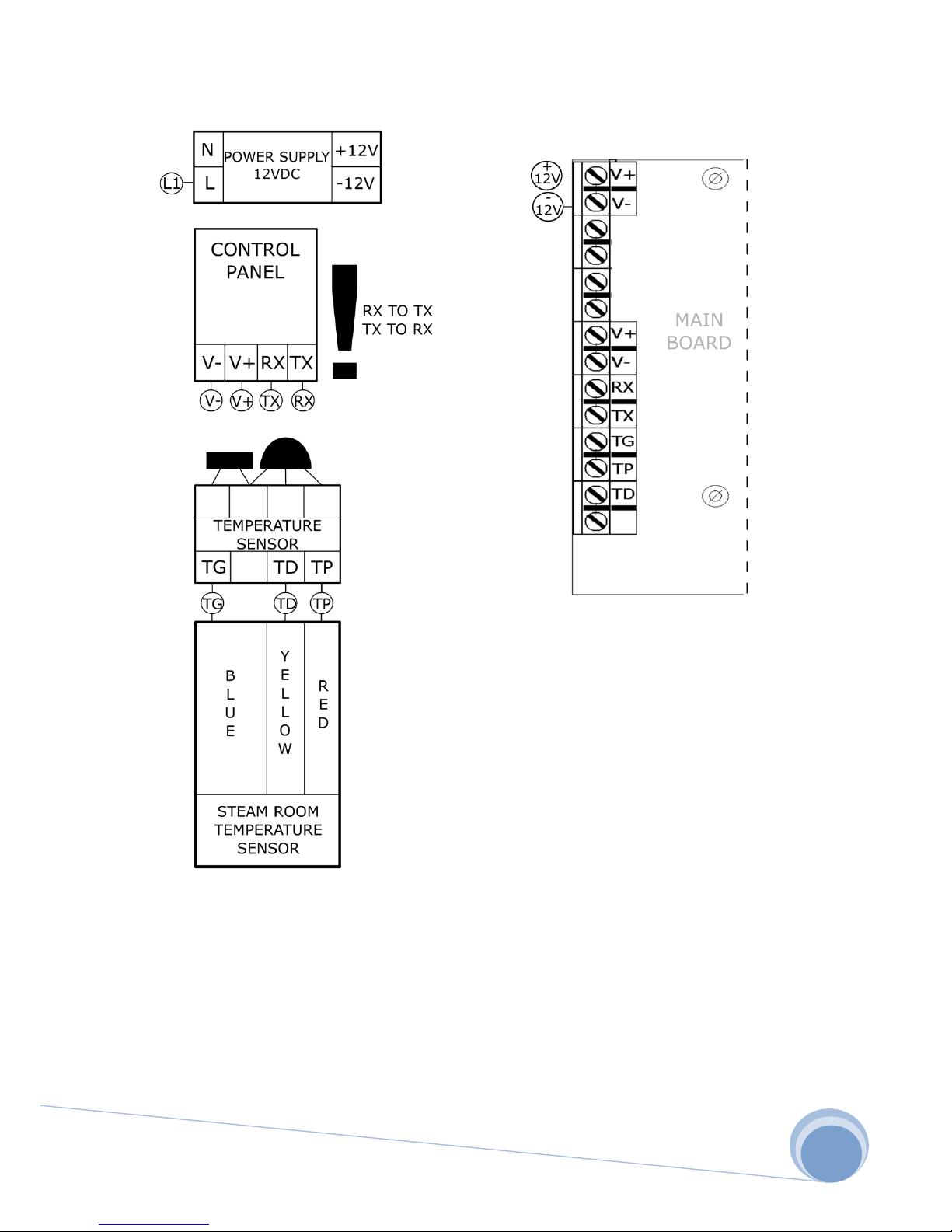
Temperature sensor, control panel
Page 18
FFES- FABRYCKI FUTURE ELECTRONIC SOLUTIONS 2016
18
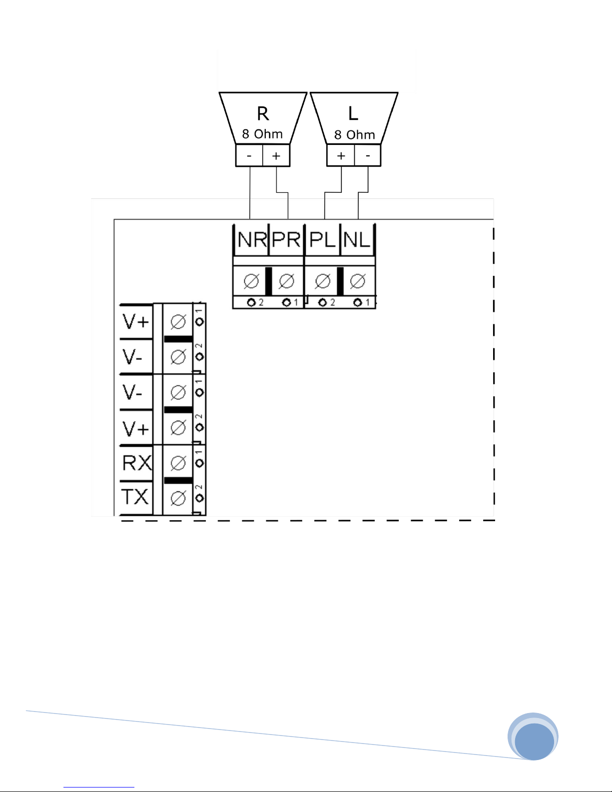
Audio
Page 19

FFES- FABRYCKI FUTURE ELECTRONIC SOLUTIONS 2016
19
4. Terms of warranty
1. The warranty on the correct operation of the controller, confirmed by stamp and
signature of the fitter/seller, is granted for a period of 24 months from the date of
purchase.
2. The warranty does not cover:
a) Removing security seals
b) Incorrect connection of the controller or components
c) The use of components with a higher wattage than recommended
d) Incorrect placement of the controller or components
e) Inappropriate operating conditions of the controller or components.
3. A necessary condition to make a claim is proof of purchase and the completed
warranty card (located on the next page).
4. Range and method of warranty repair is established by the warrantor.
5. After its third repair, a component (main board, control panel, temperature sensor) is
replaced with a new one.
6. Repairs are carried out in the door to door system.
7. The repair time cannot last longer than 7 days from the date of shipment.
8. Complaints should be submitted to the address of the selling company or directly to
the manufacturer.
9. In case the claim proves to be unjustified, the costs associated with shipping are
covered by the applicant.
Page 20

FFES- FABRYCKI FUTURE ELECTRONIC SOLUTIONS 2016
20
Warranty Card
MODEL Z………
Date
Description
Stamp and signature of
the seller
User signature
Page 21

FFES- FABRYCKI FUTURE ELECTRONIC SOLUTIONS 2016
21
FFES controller, series ZXX, is an electronic device. According to the
directives obliging in the European Union, it cannot be disposed of with
other household waste. Such a product should be returned to a special
WEEE facility.
 Loading...