

Page 1
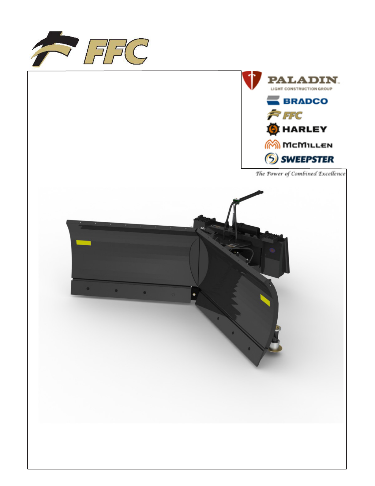
OPERATOR'S & PARTS MANUAL
V-Snow Blade
Model Number_______________________
Serial Number___________________________
800-456-7100 www.paladinlcg.com 2800 N. Zeeb Rd., Dexter, MI. 48130 United States of America
Manual Number: 51-4320
Release Date: December 2010
Serial Number 1052001 and Up
1
Page 2

Notes
2
Page 3

TABLE OF CONTENTS
PREFACE .....................................................................................................................................................4
SAFETY STATEMENTS ...............................................................................................................................5
GENERAL SAFETY PRECAUTIONS........................................................................................................5-7
EQUIPMENT SAFETY PRECAUTIONS ......................................................................................................8
SAFETY DECALS & LABELS ......................................................................................................................9
INSTALLATION .........................................................................................................................................10
OPERATION ..........................................................................................................................................11-19
MAINTENANCE SCHEDULE .....................................................................................................................20
MAINTENANCE RECORD .........................................................................................................................21
MAINTENANCE ...................................................................................................................................22-23
TROUBLESHOOTING ..........................................................................................................................24-28
PRODUCT SPECIFICATIONS ...................................................................................................................47
BOLT TORQUE SPECIFICATIONS ...........................................................................................................48
HYDRAULIC TORQUE SPECIFICATIONS ...........................................................................................49-50
WARRANTY ...............................................................................................................................................51
3
Page 4

PREFACE
GENERAL INFORMATION
This product was carefully designed and manufactured to give you many years of dependable service.
Only minor maintenance (such as cleaning and lubricating) is required to keep it in top working condition.
Be sure to observe all maintenance procedures and safety precautions in this manual and on any safety
decals located on the product and on any equipment on which the attachment is mounted.
WARNING! Never let anyone operate this unit without reading the “Safety Precautions” and
“Operating Instructions” sections of this manual. Always choose hard, level ground
to park the vehicle on and set the brake so the unit cannot roll.
Unless noted otherwise, right and left sides are determined from the operator’s control position when facing
the attachment.
NOTE: The illustrations and data used in this manual were current (according to the information
available to us) at the time of printing, however, we reserve the right to redesign and change the
attachment as may be necessary without notication.
BEFORE OPERATION
The primary responsibility for safety with equipment falls to the operator. Make sure the equipment is
operated only by trained individuals that have read and understand this manual. If there is any portion of
this manual or function you do not understand, contact your local authorized dealer or manufacturer to
obtain further assistance. Keep this manual available for reference. Provide this manual to any new owners
and/or operator’s
SAFETY ALERT SYMBOL
This is the “Safety Alert Symbol” used by this industry. This symbol is used to warn of
possible injury. Be sure to read all warnings carefully. They are included for your safety and
the safety of others working with you.
SERVICE
Use only manufacturer replacement parts. Substitute parts may not meet the required standards.
Record the model and serial number of your unit on the cover of this manual. The parts department
needs this information to insure that you receive the correct parts.
SOUND AND VIBRATION
“Sound pressure levels and vibration data for this attachment are inuenced by many different parameters;
some items are listed below (not inclusive):
• prime mover type, age, condition, with or without cab enclosure and conguration
• operator training, behavior, stress level
• job site organization, working material condition, environment
Based on the uncertainty of the prime mover, operator, and job site, it is impossible to get precise machine
and operator sound pressure levels, or vibration levels for this attachment.”
4
Page 5

SAFETY STATEMENTS
DANGER! THIS SIGNAL WORD IS USED WHERE SERIOUS INJURY OR DEATH WILL RESULT IF
THE INSTRUCTIONS ARE NOT FOLLOWED PROPERLY.
WARNING! THIS SIGNAL WORD IS USED WHERE SERIOUS INJURY OR DEATH COULD RESULT
IF THE INSTRUCTIONS ARE NOT FOLLOWED PROPERLY.
CAUTION! THIS SIGNAL WORD IS USED WHERE MINOR INJURY COULD RESULT IF THE
INSTRUCTIONS ARE NOT FOLLOWED PROPERLY.
NOTICE! NOTICE INDICATES A PROPERTY DAMAGE MESSAGE.
THIS SYMBOL BY ITSELF OR USED WITH A WARNING WORD THROUGHOUT THIS
MANUAL IS USED TO CALL YOUR ATTENTION TO INSTRUCTIONS INVOLVING YOUR
PERSONAL SAFETY OR THE SAFETY OF OTHERS. FAILURE TO FOLLOW THESE
INSTRUCTIONS CAN RESULT IN INJURY OR DEATH.
GENERAL SAFETY PRECAUTIONS
WARNING! READ MANUAL PRIOR TO INSTALL
Improper installation, operation, or maintenance of this equipment could result in serious
injury or death. Operators and maintenance personnel should read this manual as well as
all manuals related to this equipment and the prime mover thoroughly before beginning
installation, operation, or maintenance. FOLLOW ALL SAFETY INSTRUCTIONS IN THIS
MANUAL AND THE PRIME MOVERS MANUAL.
WARNING! READ AND UNDERSTAND ALL SAFETY STATEMENTS
Read all safety decals and safety statements in all manuals prior to operating or working
on this equipment. Know and obey all OSHA regulations, local laws and other professional
guidelines for your operation. Know and follow good work practices when assembling,
maintaining, repairing, mounting, removing or operating this equipment.
KNOW YOUR EQUIPMENT
Know your equipment’s capabilities, dimensions and operations before operating. Visually
inspect your equipment before you start, and never operate equipment that is not in proper
working order with all safety devices intact. Check all hardware to assure it is tight. Make
certain that all locking pins, latches, and connection devices are properly installed and
secured. Remove and replace any damaged, fatigued or excessively worn parts. Make
certain all safety decals are in place and are legible. Keep decals clean, and replace them if
they become worn and hard to read.
WARNING! PROTECT AGAINST FLYING DEBRIS
Always wear proper safety glasses, goggles or a face shield when driving pins in or out or
when operation causes dust, ying debris, or any other hazardous material.
5
Page 6
GENERAL SAFETY PRECAUTIONS
WARNING! LOWER OR SUPPORT RAISED EQUIPMENT
Do not work under raised booms without supporting them. Do not use support material made
of concrete blocks, logs, buckets, barrels or any other material that could suddenly collapse
or shift positions. Make sure support material is solid, not decayed, warped, twisted, or
tapered. Lower booms to ground level or onto blocks. Lower booms and attachments to the
ground before leaving the cab or operator’s station.
WARNING! USE CARE WITH HYDRAULIC FLUID PRESSURE
Hydraulic uid under pressure can penetrate the skin and cause serious injury or death.
Hydraulic leaks under pressure may not be visible. Before connecting or disconnecting
hydraulic hoses, read your prime movers operator’s manual for detailed instructions on
connecting and disconnecting hydraulic hoses or ttings.
• Keep unprotected body parts, such as face, eyes, and arms as far away as possible from
a suspected leak. Flesh injected with hydraulic uid may develop gangrene or other
permanent disabilities.
• If injured by injected uid, see a doctor at once. If your doctor is not familiar with this type
of injury, ask him to research immediately to determine proper treatment.
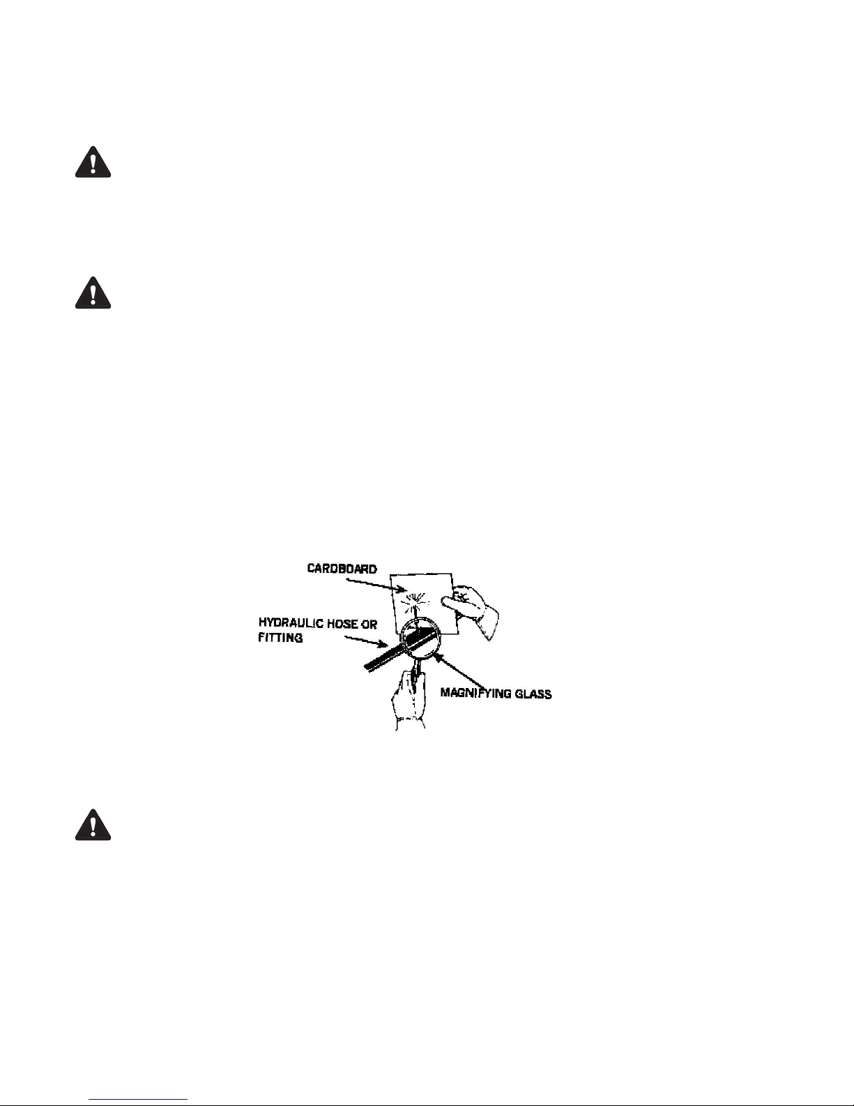
• Wear safety glasses, protective clothing, and use a sound piece of cardboard or wood
when searching for hydraulic leaks.
DO NOT USE YOUR HANDS!
SEE ILLUSTRATION.
WARNING! DO NOT MODIFY MACHINE OR ATTACHMENTS
Modications may weaken the integrity of the attachment and may impair the function,
safety, life and performance of the attachment. When making repairs, use only the
manufacturer’s genuine parts, following authorized instructions. Other parts may be
substandard in t and quality. Never modify any ROPS (Roll Over Protection System)
equipment or device. Any modications must be authorized in writing by the manufacturer.
6
Page 7

GENERAL SAFETY PRECAUTIONS
WARNING! SAFELY MAINTAIN AND REPAIR EQUIPMENT
•Do not wear loose clothing, or any accessories that can catch in moving parts. If you have
long hair, cover or secure it so that it does not become entangled in the equipment.
•Work on a level surface in a well-lit area.
•Use properly grounded electrical outlets and tools.
•Use the correct tool for the job at hand. Make sure they are in good condition for the task
required.
•Wear the protective equipment specied by the tool manufacturer.
WARNING! SAFELY OPERATE EQUIPMENT
Do not operate equipment until you are completely trained by a qualied operator in how to
use the controls, know its capabilities, dimensions, and all safety requirements. See your
prime movers manual for these instructions.
•Keep all step plates, grab bars, pedals, and controls free of dirt, grease, debris, and oil.
•Never allow anyone to be around the equipment when it is operating.
•Do not allow riders on the attachment or the prime mover.
•Do not operate the equipment from anywhere other than the correct operators position.
•Never leave equipment unattended with the engine running or with this attachment in a
raise position.
•Do not alter or remove any safety feature from the prime mover or this attachment.
•Know your work site safety rules as well as trafc rules and ow. When in doubt on any
safety issue, contact your supervisor or safety coordinator for an explanation.
EQUIPMENT SAFETY PRECAUTIONS
WARNING! EXPOSURE TO RESPIRABLE CRYSTALLINE SILICA DUST ALONG WITH OTHER
HAZARDOUS DUSTS MAY CAUSE SERIOUS OR FATAL RESPIRATORY DISEASE.
It is recommended to use dust suppression, dust collection and if necessary personal
protective equipment during the operation of any attachment that may cause high levels of
dust.
WARNING! REMOVE PAINT BEFORE WELDING OR HEATING.
Hazardous fumes/dust can be generated when paint is heated by welding, soldering or
using a torch. Do all work outside or in a well ventilated area and dispose of paint and
solvent properly. Remove paint before welding or heating.
When sanding or grinding paint, avoid breathing the dust. Wear an approved respirator.
If you use solvent or paint stripper, remove stripper with soap and water before welding.
Remove solvent or paint stripper containers and other flammable material from area. Allow
fumes to disperse at least 15 minutes before welding or heating.
WARNING! END OF LIFE DISPOSAL.
At the completion of the useful life of the unit, drain all fluids and dismantle by
separating the different materials (rubber, steel, plastic, etc.). Follow all federal, state
and local regulations for recycling and disposal of the fluid and components.
7
Page 8

EQUIPMENT SAFETY PRECAUTIONS
Operating the V-Snow Blade:
•Do not exceed the lifting capacity of your prime mover.
•Operate only from the operator’s station.
•When operating on slopes, drive up and down, not across. Avoid steep hillside operation
which could cause the prime mover to over turn.
•Reduce speed when driving over rough terrain, on a slope, or turning to avoid overturning
the vehicle.
•An operator must not use drugs or alcohol, which can change his or her alertness or
coordination. An operator taking prescription or over-the-counter drugs should seek
medical advice on whether or not he or she can safely operate equipment.
•Before exiting the prime mover, lower the attachment to the ground, apply the brakes, turn
off the prime mover’s engine and remove the key.
Transporting the V-Snow Blade:
•Travel only with the attachment in a safe transport position to prevent uncontrolled
movement. Drive slowly over rough ground and on slopes.
•When driving on roads use safety lights, reflectors, Slow Moving Vehicle signs etc. to
prevent accidents. Check local government regulations that may affect you.
•Do not drive close to ditches, excavation, etc. cave in could result.
Maintaining the V-Snow Blade:
•Before performing maintenance (unless otherwise specified) lower the attachment to the
ground, apply the brakes, turn off the engine and remove the key.
•Never perform any work on the attachment unless you are authorized and qualified to do
so. Always read the operator service manual’s before any repair is made. After completing
maintenance or repair, check for correct functioning of the attachment. If not functioning
properly, always tag “DO NOT OPERATE” until all problems are corrected.
•Worn, damaged or illegible safety decals must be replaced. New safety decals can be
ordered from FFC.
•Never make hydraulic repairs while system is under pressure. Serious personal injury or
death could result.
•Never work under a raised attachment.
8
Page 9
Serial
Number Tag
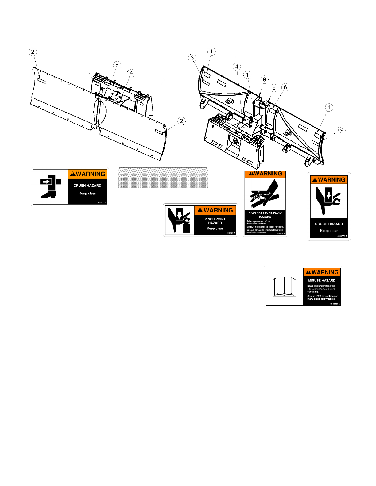
SAFETY DECALS & LABELS
2. & 3. RDL3132 & RDL3131
1. 50-0721
Item Part Qty Description
5. 50-0737
4. 50-0724
9. 50-0775
1. 50-0721 3 Label, Warning, Crush Hazard
2. RDL3132 2 Label,Amber,ReectiveTape,2x6
3. RDL3131 2 Label,Red,ReectiveTape,2x6
4. 50-0724 1 Label, Warning, High Pressure Fluid
5. 50-0737 1 Label,Warning,PinchPointHazard
6. 50-10017 1 Label,Warning,AvoidSeriousInjury
9. 50-0775 2 Label, Warning, Crush Hazard
6. 50-10017
Use part numbers to order replacements for lost or damaged decals. Be sure to read all decals before
operating the attachment. They contain information you need to know for both safety and longevity.
Placement or replacement of Safety Signs
1. Clean the
area of application with nonammable solvent, and then wash the same area with soap and water.
2. Allow the surface to fully dry.
3. Remove the backing from the safety sign, exposing the adhesive surface.
4. Apply the safety sign to the position shown in the diagram above and smooth out any bubbles.
Instructions
1. Keep all safety signs clean and legible.
2. Replace all missing, illegible, or damaged safety signs.
3. Replacement parts, for parts with safety signs attached, must also have safety signs attached.
4. Safety signs are available, free of charge, from your dealer or from SWEEPSTER.
9
Page 10

INSTALLATION
V-Snow Blade Installation
WARNING! Improper attachment of V-Snow Blade could result in injury or death. Do not operate
this machine until you have positive indication that the attachment is securely mounted.
1. Position the blade on a level surface.
2. Enter the prime mover.
3. Fasten the safety restraints.
4. Start the engine.
5. Disengage the parking brake.
6. Align the attachment mechanism with the mounting on the blade and attach it to the prime mover.
Follow the attaching procedure in the prime mover owner’s manual.
7. Engage the parking brake and shut down the prime mover. Relieve all pressure to the auxiliary
hydraulic lines.
8. Unfasten safety restraints and exit the prime mover.
9. Ensure that the hydraulic quick couplers are clean. Connect hydraulic lines for the blade to the prime
mover. Twist the collar of the quick couplers one quarter of a turn, to secure the hydraulic connection.
10. While the loader arms are lowered, visually inspect the attachment mechanism to ensure that it is
securely mounted.
11. Enter prime mover, fasten safety restraints and start prime mover.
12. Carefully raise the loader and cycle the rollback/dump cylinders to check clearances, that limiting
stops make proper contact and verify that all mounting procedures have been successfully completed.
Contact FFC for instructions if the limiting stops do not contact properly.
10
Page 11

INSTALLATION
Removing the V-Snow Blade
WARNING! Serious injury or death may result from disengaging the blade when the blade is
in an unstable position. Place blade on a rm, level surface in a stable position before
disengaging.
NOTICE! HOSES FOR THE BLADE MUST BE REMOVED BEFORE THE QUICK ATTACH IS
DISENGAGED. Pulling the blade with the hoses could result in damage to the prime mover
or to the blade.
1. Position the blade on a level surface.
2. Congure the blade in either the “scoop” or “straight” position (for positions refer to angling instructions
in operations). Never disengage the blade when it is in the “V” position.
3. Lower the blade to the ground.
4. Tilt the blade until the mounting is on the ground.
5. Engage the parking brake and shut off the prime mover. Relieve the pressure to the auxiliary hydraulic
lines.
6. Unfasten safety restraints and exit prime mover.
7. Disconnect the blades hydraulic lines from the prime mover and connect the quick couplers together to
keep them clean.
8. Disengage attachment locking mechanism (consult prime mover manual).
9. Enter prime mover, fasten safety restraints and start the prime mover.
10. Disengage the parking brake and back away the blade.
WARNING! AFTER BACKING AWAY BE SURE BLADE MOUNTING IS CONTACTING THE GROUND.
If not in contact with ground, blade will be unstable and serious injury or death may occur.
11
Page 12

OPERATION
INTENDED USE:
This blade is designed solely for the use in snow removal. This blade is not designed to move dirt, loose
soil or gravel. Use in any other way is considered contrary to the intended use. Compliance with and strict
adherence to operation, service and repair conditions as specied by the manufacturer, are also essential
elements of the intended use.
CAUTION! A V-SNOW BLADE IS A DEMANDING MACHINE. Only fully trained operators or trainee
operators under supervision of a fully trained person should use this machine.
Before operating blade
•Learn blade and prime mover controls in an off-road location.
•Be sure that you are in a safe area, away from trafc or other hazards.
•Check all hardware holding the blade to the host machine, making sure it is tight.
•Replace any damaged or fatigued hardware with properly rated fasteners.
•Make sure all hydraulic hardware and hydraulic ttings are tight.
•Replace any damaged or fatigued ttings or hoses.
•Remove from the plowing area all property that could be damaged by ying debris or impacts from the
blade.
•Be sure all persons not operating the blade are clear of the area being cleared.
•Always wear proper apparel; such as safety glasses, goggles or a face shield and ear protection.
While operating blade:
•When operating the blade, adhere to all government rules, local laws and other professional guidelines
for your plowing application.
•Before leaving the operators area for any reason, lower the blader to the ground. Stop the prime
mover engine, set the brakes and remove the key from the ignition.
•Keep hands, feet, hair and other loose clothing away from all moving parts.
•Leave all shields and safety equipment in place when operating the blade.
•Be aware of extra weight and width a blade adds. Reduce travel speed accordingly.
•When operating on rough terrain, reduce speed to maintain control of steering.
•Never plow toward people, buildings, vehicles or other objects that can be damaged by ying
debris.
12
Page 13
OPERATION
•Only operate the blade while you are in the seat of the prime mover. The seat belt must be
fastened while you operate the prime mover. Only operate the controls while the engine is running.
Protective glasses must be worn while you operate the prime mover and while you operate the
blade.
•While you operate the blade slowly in an open area, check for proper operation of all controls and
all protective devices. Note any repairs needed during operation of the blade. Report any needed
repairs.
Hydraulic Sequencing Model
Adjusting V-Blade:
1. Start the prime mover at idle and raise the blade.
2. Adjust the blade to the desired angle (refer to “angling instructions”) and then lower to the ground.
3. Adjust blade until it is level to the ground ( refer to “leveling instructions”).
4. Increase prime mover engine rpm to operating speed.
Angling Instructions:
Scoop Position:
Hold hydraulic ow until both blades extend
and stop.
SCOOP
Left Angle Position:
LEFT ANGLE
If starting in “V” position, hold hydraulic ow
until right blade extends and stops.
13
Page 14
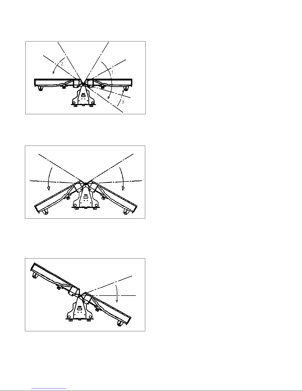
STRAIGHT
OPERATION
Straight Position:
1. If starting from the scoop position, reverse
ow until right blade completely retracts.
2. While still reversing ow, retract left blade
until it is in the straight position.
3. Use normal ow to extend right blade until
it is parallel to left blade.
V Position:
V
Reverse ow until both blades retract and
stop.
Right Angle Position:
If starting from the Scoop position, reverse
ow until right blade retracts and stops.
RIGHT ANGLE
14
Page 15
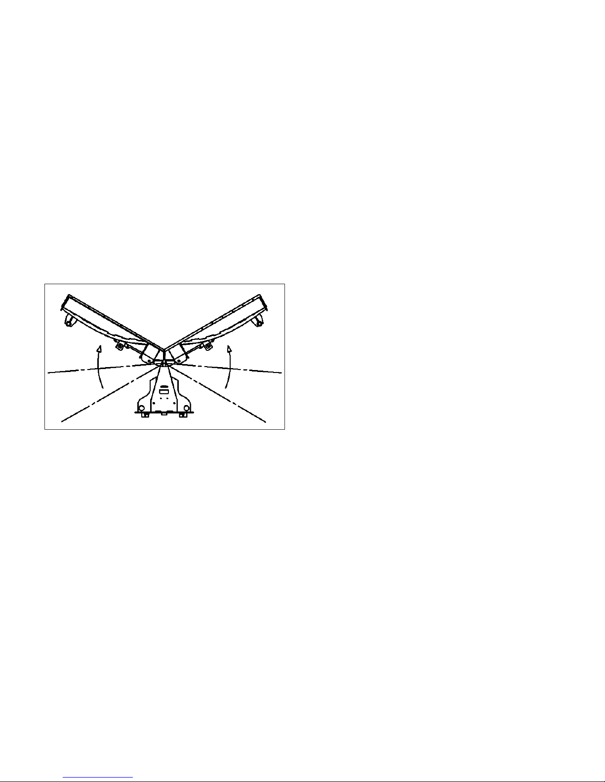
OPERATION
Electro-Hydraulic Model
Adjusting V-Blade:
1. Start the prime mover at idle and raise the blade.
2. Adjust the blade to the desired angle (refer to “angling instructions”) and then lower to the ground.
3. Adjust blade until it is level to the ground ( refer to “leveling instructions”).
4. Increase prime mover engine rpm to operating speed.
Angling Instructions:
1. Press toggle switch and hold ow to move
one blade to the desired position.
2. Release switch and ow.
3. Pull toggle switch and hold ow to move
other blade to the desired position.
4. Release switch and ow.
15
Page 16

OPERATION
Leveling Instructions
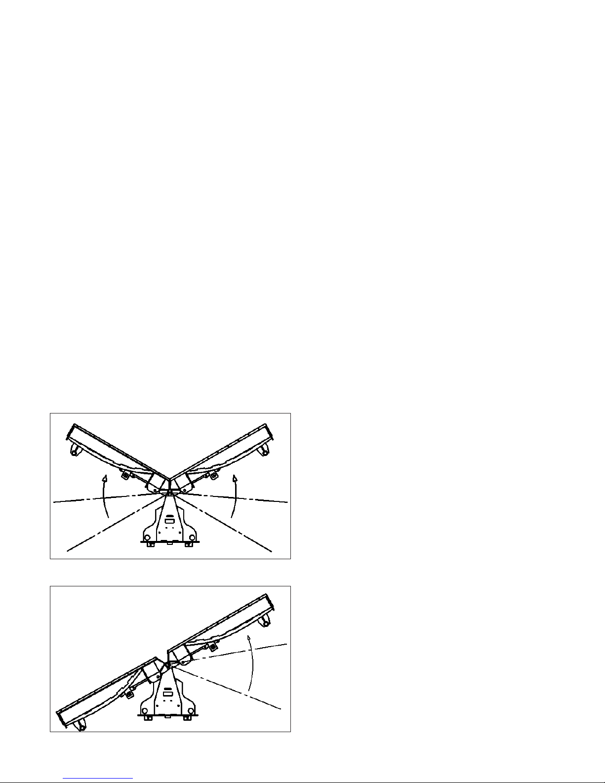
NOTICE! A LEVEL UNIT SHOULD HAVE NO VISIBLE SPACES BETWEEN CUTTING EDGES AND
PLOWING SURFACE.
Scoop Position
If the front corners of the attachment are contacting the plowing surface and a gap is visible towards the
center of the attachment (gure 2):
1. Lift attachment
2. Roll attachment backwards
3. Lower back to ground
4. Continue until level.
If the rear center of the attachment is contacting the plowing surface and a gap is visible towards the outer
sides of the attachment (gure 3):
1. Lift attachment
2. Roll attachment forward
3. Lower back to ground
4. Continue until level
V Position
If the front corner of the attachment is contacting the plowing surface and a gap is visible towards the outer
sides of the attachment (gure 2):
1. Lift attachment
2. Roll attachment backwards
3. Lower back to ground
4. Continue until level.
If the outer sides of the attachment are contacting the plowing surface and a gap is visible towards the
center of the attachment (gure 3):
1. Lift attachment
2. Roll attachment forward
3. Lower back to ground
4. Continue until level
16
Page 17
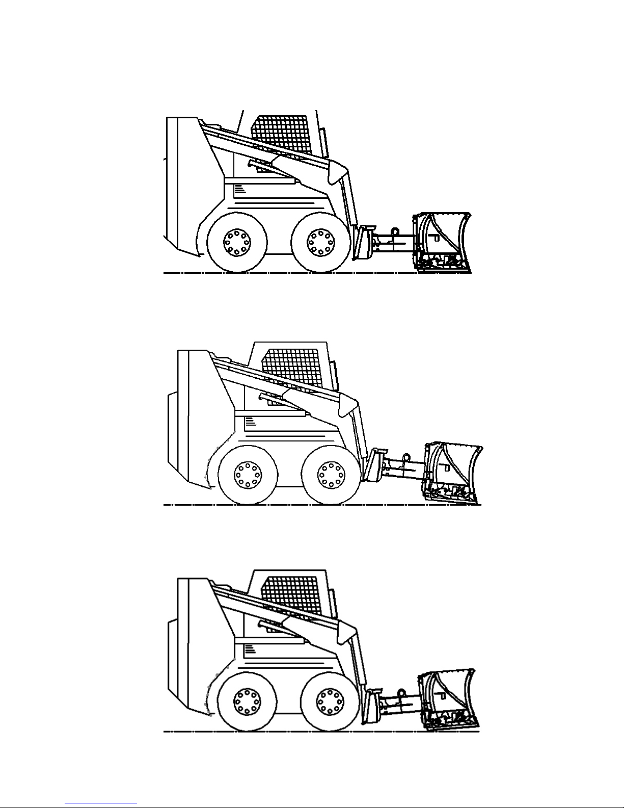
Scoop Position Shown
OPERATION
Level
gure 2
gure 3
17
Page 18
OPERATION
1. Move prime mover to a level surface with the blade properly attached.
2. Place the prime mover in “Park” and engage the parking brake.
3. Lower the blade onto the level surface.
4. Shut off prime mover engine, remove key and relieve all pressure from the hydraulic lines.
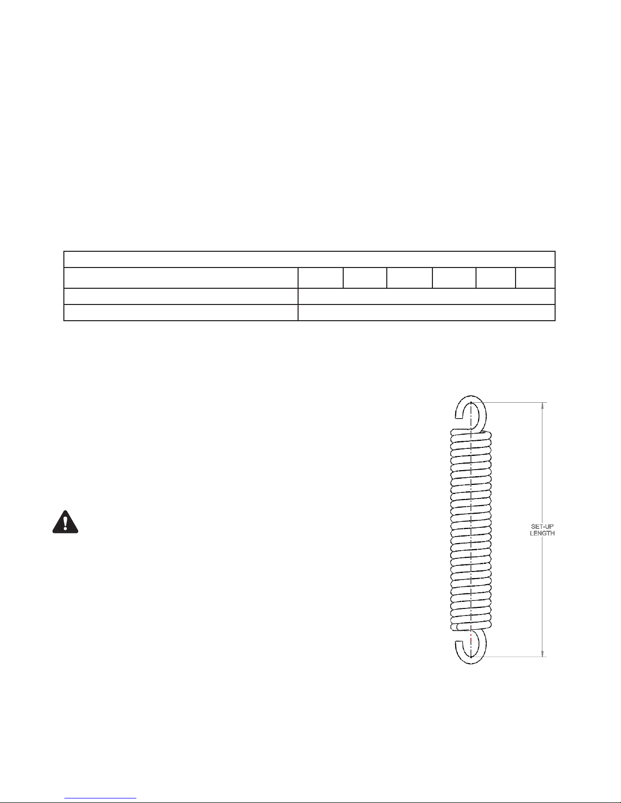
5. Check spring specications on chart below.
RECOMMENDED SPRING SET-UP LENGTHS
Blade Width 60 in 72 in 84 in 96 in 108 in 120 in
Recommended Spring Set-up Length* 14.38 inches
Maximum Length Permitted- 15.33 inches
*NOTE: The Spring set-up lengths are measured from the inside of one hook to the inside of the
other hook. The relaxed length of the spring is 14 inches.
6. Test snow blade. If edges trip too easily, perform the following steps:
a. Repeat the above steps 1 through 4.
b. Tighten the spade (or eye) bolts to lengthen the springs.
WARNING! LENGTHENING THE SPRINGS BEYOND THE MAXIMUM
LENGTH PERMITTED CAN RESULT IN DAMAGE TO THIS
PRODUCT.
c. Test your blade again. If edges still trip too easily contact FFC.
18
Page 19
OPERATION
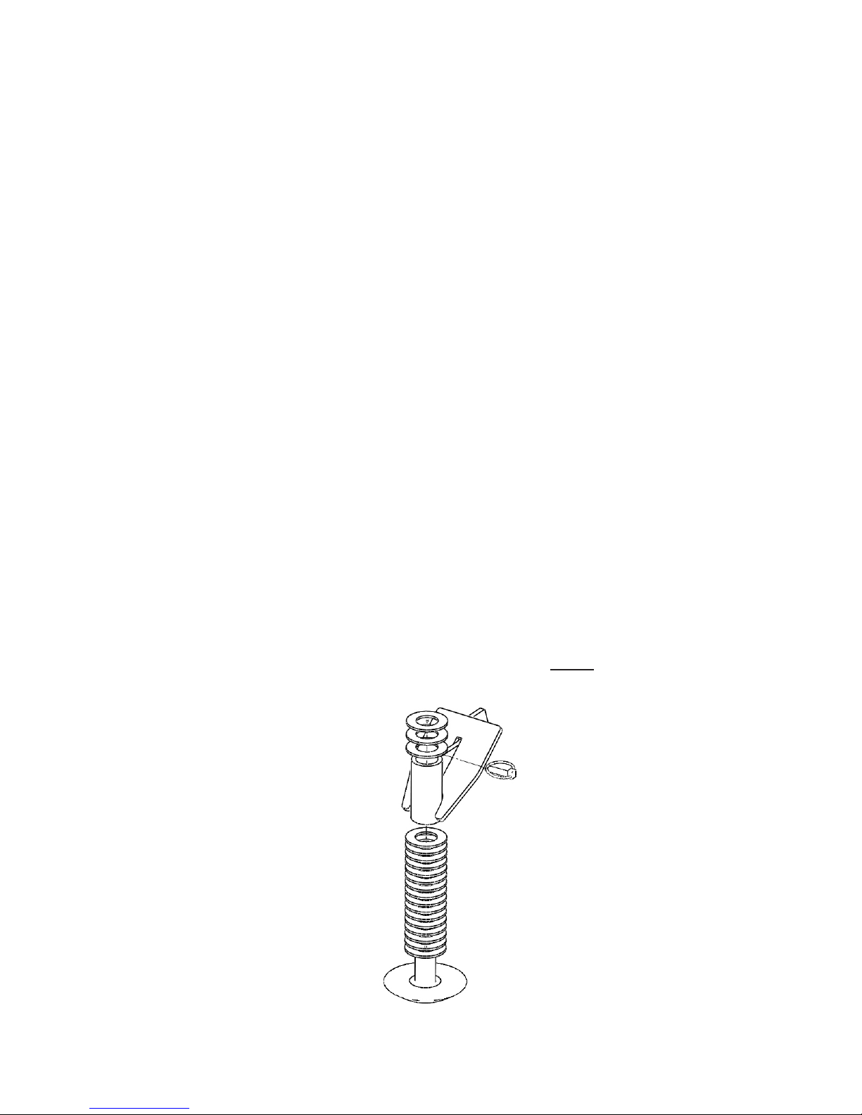
Skid Shoe Set-Up
Determine what type of surface is beneath the snow where your blade is being operated.
If the surface is hard and smooth, like concrete or asphalt, the skid shoe placement as shipped from the
factory is correct. (3 spacers on top, 16 on bottom)
If the surface is soft or uneven, then lower the shoe to the desired position (see directions and diagram
below).
Changing the position of the skid shoe :
1. Park the prime mover on a rm, level surface with blade properly attached
2. Lower the blades cutting edge onto a sturdy wood or metal blocking to safely hold the skid shoes 2.5 to
3 inches off the level surface.
3. Place prime mover in “Park” and engage parking brake.
4. Shut off the prime mover’s engine, remove the key and relieve all pressure from hydraulic lines.
5. Remove the lynch pin securing the skid shoe.
6. Adjust the positioning of the spacers to raise or lower the skid shoe.
7. Re-secure the lynch pin.
8. Repeat for the other skid shoe.
NOTICE! WHEN ADJUSTING THE SKID SHOE, ALL SPACERS MUST BE USED.
Factory Settings
(3 on Top, 16 on Bottom)
19
Page 20

OPERATION
Service & Repair
CAUTION ! DO NOT MODIFY THE V-SNOW BLADE IN ANY WAY. Personal injury could result. If you
have questions, contact your dealer or FFC.
Repair or adjust the blade in a safe area, away from trafc and other hazards.
Before adjusting or servicing, lower the blade to the ground, set parking brake, shut down the prime
mover and remove the key from the ignition.
When working on or around the blade, safely secure it from falling or shifting.
Service & Repair - Hydraulic Safety
Stop the prime mover engine and release hydraulic pressure before servicing or adjusting blade hydraulic
systems.
WARNING! Escaping hydraulic uid can have enough pressure to penetrate the skin, causing
serious personal injury.
Check lines, tubes and hoses carefully. Do not use your hand to check for leaks. Use a board or cardboard
to check for leaks. Tighten all connections to the recommended torque.
Do not bend high pressure lines. Do not strike high pressure lines, Do not install bent lines, bent tubes, or
kinked hoses. Do not install damaged lines, tubes, or hoses.
Repair loose lines, tubes, and hoses. Replace damaged lines, tubes, and hoses. Leaks can cause res.
See your dealer for repair or replacement parts.
Replace the parts if any of the following conditions are present:
• The end ttings are damaged or leaking.
• The outer covering is chafed or cut.
• The reinforcing wire layer is exposed.
• The outer covering is ballooning locally.
• The hose is kinked or crushed.
• The hose has been pulled or stretched.
Make sure that all clamps, guards, and shields are installed correctly.
20
Page 21

OPERATION
General Storage:
NOTICE! Do not store in direct sunlight. Materials will deteriorate prematurely if stored in direct
sunlight. Do not store near intense heat.
Storage:
• Clean the unit thoroughly, removing all mud, dirt and grease.
• Inspect for visible signs of wear, breakage or damage. Order any parts required and make the
necessary repairs to avoid delays upon removal from storage.
• Tighten loose nuts, capscrews and hydraulic connections.
• Coat exposed portions of the cylinder rods with grease.
• Lubricate grease ttings.
• Seal hydraulic system from contaminants and secure all hydraulic hoses off the ground to help prevent
damage.
• Store unit in a dry and protected place. Leaving the unit outside will materially shorten its life.
Additional Precautions for Long Term Storage:
• Touch up all unpainted surfaces with paint to avoid rust.
• Inate tires to recommended tire pressure.
• Fill fuel tank and hydraulic oil tank to maximum.
• Check antifreeze properties and drain uids as appropriate.
Removal from Storage:
• Remove cover.
• Wash unit and replace any damage and/or missing parts.
• Lubricate grease ttings.
• Check hydraulic hoses for damage and replace as necessary.
21
Page 22
OPERATION
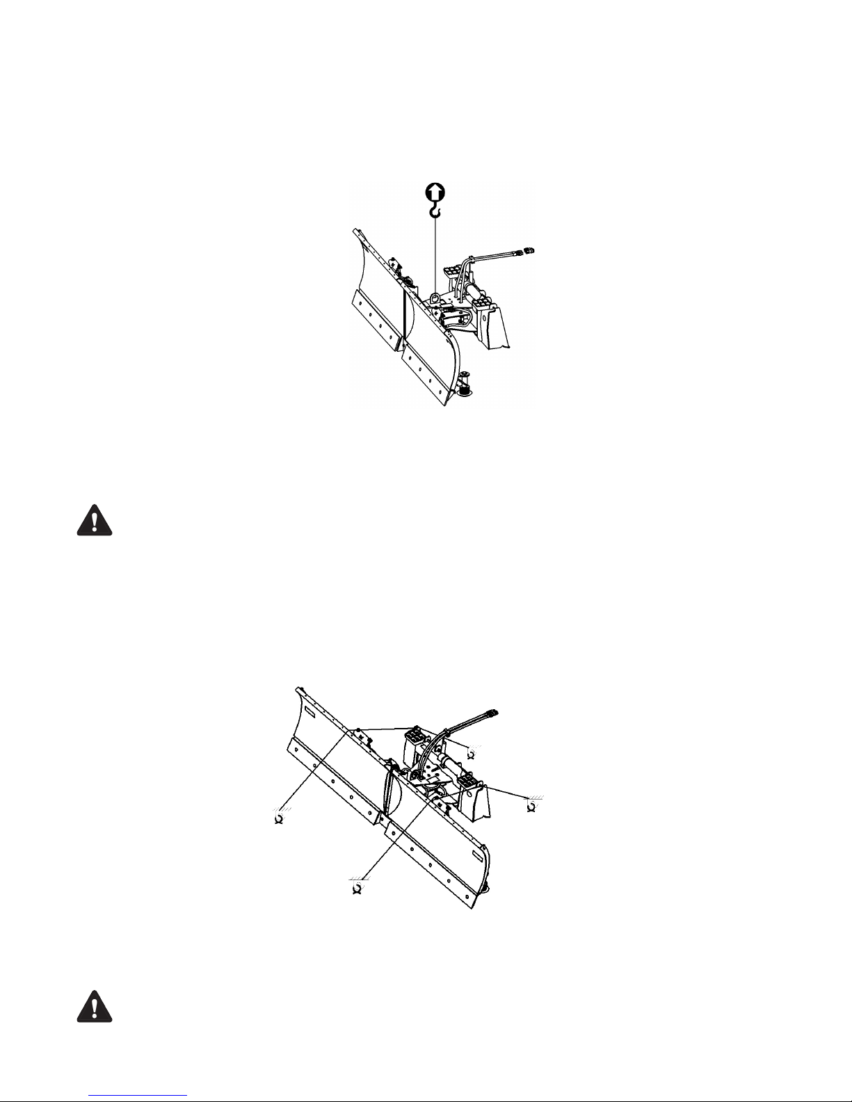
LIFT POINTS
Lifting points are identied by lifting decals where required. Lifting at other points is unsafe and can
damage attachment. Do not attach lifting accessories around cylinders or in any way that may damage
hoses or hydraulic components. See diagram:
• Attach lifting accessories to unit at recommended lifting points.
• Bring lifting accessories together to a central lifting point.
• Lift gradually, maintaining the equilibrium of the unit.
WARNING! USE LIFTING ACCESSORIES (CHAINS, SLINGS, ROPES, SHACKLES AND ETC.) THAT
ARE CAPABLE OF SUPPORTING THE SIZE AND WEIGHT OF YOUR ATTACHMENT.
Secure all lifting accessories in such a way to prevent unintended disengagement.
Failure to do so could result in the attachment falling and causing serious personal
injury or death.
TIE DOWN POINTS
Tie down points are identied by tie down decals where required. Securing to trailer at other points is
unsafe and can damage attachment. Do not attach tie down accessories around cylinders or in any way
that may damage hoses or hydraulic components. See diagram:
• Attach tie down accessories to unit as recommended.
• Check unit stability before transporting.
WARNING! VERIFY THAT ALL TIE DOWN ACCESSORIES (CHAINS, SLINGS, ROPES,
SHACKLES AND ETC.) ARE CAPABLE OF MAINTAINING ATTACHMENT STABILITY
DURING TRANSPORTING and are attached in such a way to prevent unintended
disengagement or shifting of the unit. Failure to do so could result in serious
personal injury or death.
22
Page 23
Maintenance Schedule
MAINTENANCE SCHEDULE
Procedure Before
Each Use
Fittings/Hoses, Hydraulic - Check for leaks/Tighten
Check for damage
Fittings, Zerk - Grease (See lubrication points)
Oil, Hydraulic - Check level
Hardware - Check for tightness
Oil Cleanliness Requirements
NOTICE! All hydraulic uid shall be ltered before use in any FFC product to obtain the ISO
cleanliness standard of 17-14 or better, unless explicitly specied otherwise.
After
Each Use
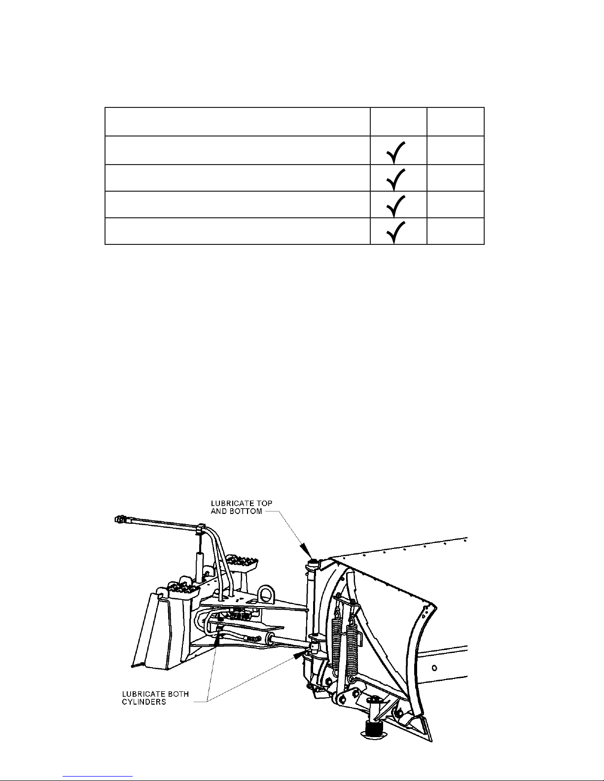
Lubrication Points
The following grease ttings should be greased before each use. See gure for locations.
1. Cylinders (2 ttings per cylinder)
2. Center Pin (2 ttings)
3. Ball Joint (B-Design, 1 tting)
23
Page 24

MAINTENANCE RECORD
Date
Maintenance Procedure Performed
Performed by Comments
24
Page 25
MAINTENANCE
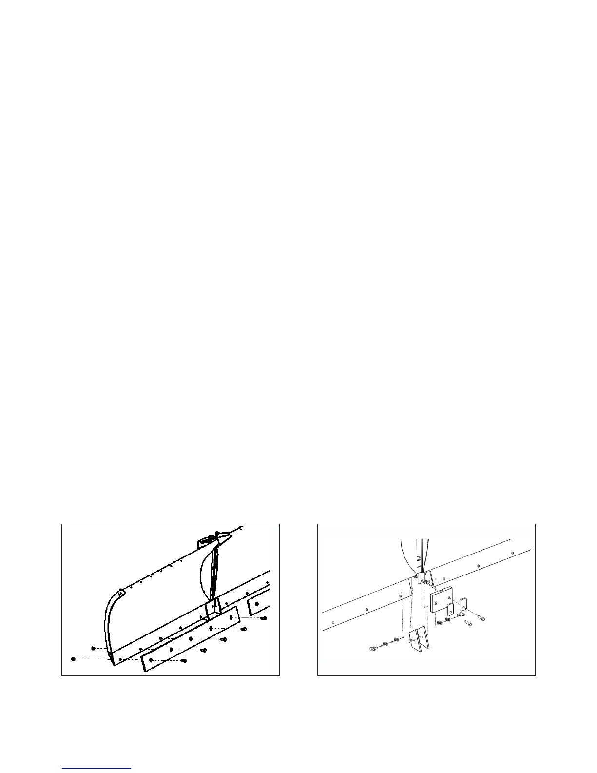
Inverting Front Wear Edges
NOTICE! All nuts and bolts must be installed using proper torque specications (refer to Bolt
Torque Specications).
1. Park prime mover on a rm, level surface with blade properly attached.
2. Lower the blades cutting edge onto a sturdy wood or metal blocking positioned under the pivoting
assembly, to safely hold the wear edge 6 to 8 inches above the level surface.
3. Place primer mover in “Park” and engage parking brake.
4. Remove and retain all nuts and bolts but the ones at each end of the wear edge.
5. Support one end of the wear edge, remove the nut and bolt, then lower it to the level surface.
6. Support the other end, remove the nut and bolt and lower to the level surface.
7. Flip the edge over so the worn side is facing up.
8. Support one end of the wear edge and re-install nut and bolt.
9. Support the other end and re-install nut and bolt
10. Re-install all nuts and bolts.
11. Repeat steps 4-10 for other wear edge.
12. Center rubber wear edge and plates must also be inverted with wear edges.
NOTICE! When installing nuts and bolts on center rubber wear edge, DO NOT tighten to
specied torque. Tighten until the retaining plate has slightly compressed the rubber.
Front Wear Edges Center Wear Edges
25
Page 26
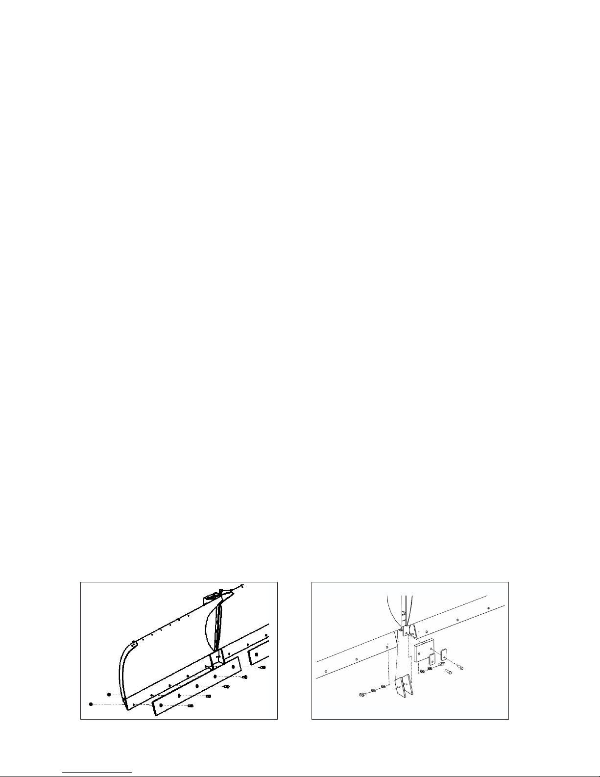
MAINTENANCE
Installing New Front Wear Edges
NOTICE! All nuts and bolts must be installed using proper torque specications (refer to Bolt
Torque Specications).
1. Park prime mover on a rm, level surface with blade properly attached.
2. Place primer mover in “Park” and engage parking brake.
3. Lower the blades cutting edge onto a sturdy wood or metal blocking, positioned under the pivoting
assembly, to safely hold the wear edge 6 to 8 inches above the level surface.
4. Remove and retain all nuts and bolts but the ones at each end of the wear edge.
5. Support one end of the wear edge, remove the nut and bolt, then lower it to the level surface.
6. Support the other end, remove the nut and bolt and lower to the level surface.
7. Discard used wear edge and all nuts and bolts.
8. Support one end of the new wear edge and install with a new nut and bolt.
9. Support the other end and install a new nut and bolt
10. Install all new nuts and bolts.
11. Repeat steps 4-10 for other wear edge.
12. Install center rubber wear edge and plates with new nuts and bolts.
NOTICE! When installing new center wear edges , 2 lock washers must be used on each bolt
for proper spacing to prevent premature wear.
NOTICE! When installing nuts and bolts on center rubber wear edge, DO NOT tighten to
specied torque. Tighten until the retaining plate has slightly compressed the rubber.
Front Wear Edges Center Wear Edges
26
Page 27

MAINTENANCE
Installing New Polyurethane Wear Edges
NOTICE! All nuts and bolts must be installed using proper torque specications (refer to Bolt
Torque Specications).
NOTICE! Improper installation of edges will result in damage to plowing surface and premature
wearing of edges.
1. Park prime mover on a rm, level surface with blade properly attached.
2. Lower the blades cutting edge onto a sturdy wood or metal blocking, positioned under the pivoting
assembly, to safely hold the wear edge 6 to 8 inches above the level surface.
3. Place primer mover in “Park” and engage parking brake.
4. Remove and retain all nuts and bolts but the ones at each end of the wear edge.
5. Support one end of the wear edge, remove the nut and bolt, then lower it to the level surface.
6. Support the other end, remove the nut and bolt and lower to the level surface.
7. Store wear edges and all nuts and bolts for possible future use.
8. Support one end of the new wear edge and install with a new nut and bolt.
9. Support the other end and install a new nut and bolt
10. Install all new nuts and bolts.
11. Repeat steps 4-10 for other wear edge.
12. Install center rubber wear edge and plates with new nuts and bolts.
NOTICE! When installing nuts and bolts on center rubber wear edge, DO NOT tighten to
specied torque. Tighten until the retaining plate has slightly compressed the rubber.
27
Page 28
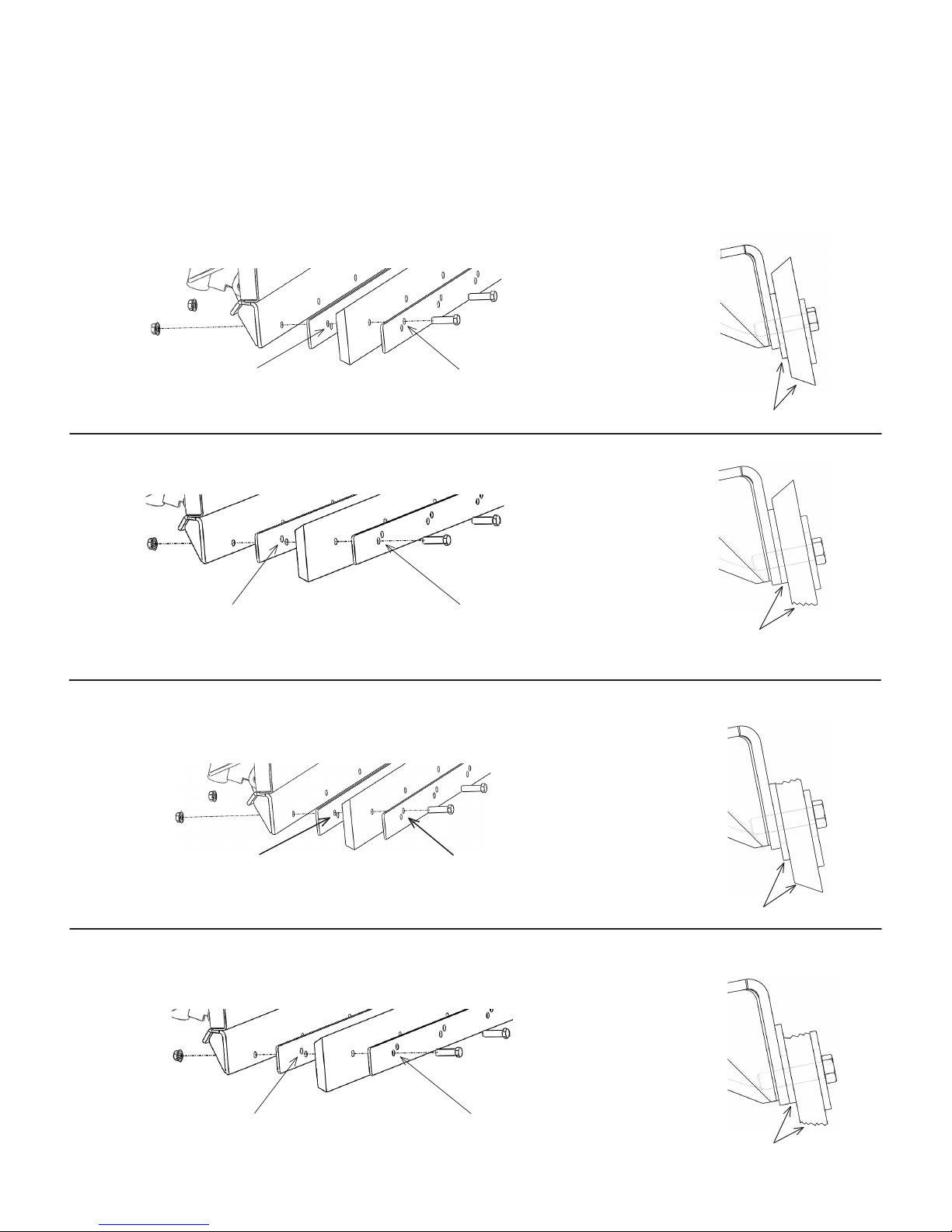
MAINTENANCE
Adjusting and Inverting the Polyurethane Wear Edges
NOTICE! The retaining plate between the polyurethane edge and the blade mounting has the
holes closest to the ground while the front retaining plate has its holes near the top.
Initial Installation Position
Holes are near the bottom with
the bolts in the upper holes.
Adjustment for Worn Edge
Holes are near the bottom with
the bolts in the lower holes.
Note retaining
plate positions
Holes are near the top with the
bolts in the upper holes.
Holes are near the top with the
bolts in the lower holes.
Flipping Worn Edge Over
Flip wear edge over and re-install
Holes are near the bottom with
the bolts in the upper holes.
Adjustment for Worn Edge
Holes are near the bottom with
the bolts in the lower holes.
Holes are near the top with the
bolts in the upper holes.
Holes are near the top with the
bolts in the lower holes.
28
Page 29
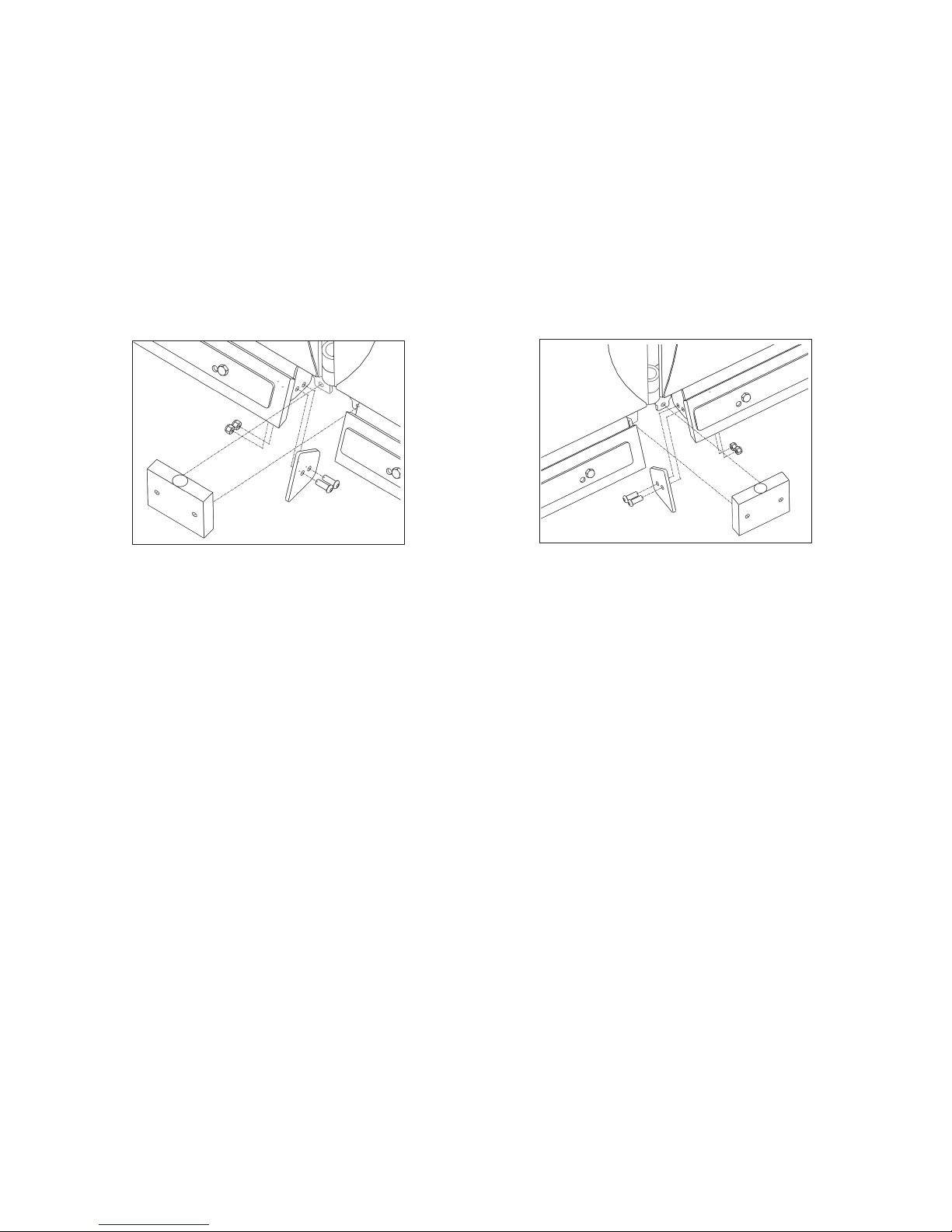
MAINTENANCE
Installing Center Nylon and Rubber Wear Edges
1. Remove all hardware and the original steel center edges and rubber center edge. Retain all for use with
original steel wear edges.
2. Install new center rubber wear edge and nylon center edges.
NOTICE! Use only 20 FT/LBS of torque on button head bolts for nylon center edges.
Inverting the Center Nylon and Rubber Wear Edges
1. Remove hardware from rubber center edge and nylon center edges.
2. Flip over the center rubber edge and center nylon edges.
3. Re-install center rubber and nylon edges.
NOTICE! Use only 20 FT/LBS of torque on button head bolts for nylon center edges.
29
Page 30

Wear Edges
Problem Possible Cause Possible Solution
Steel or Poly edges are wearing
unevenly
A noticeable trail of snow is
being left when plowing.
Trip Edges
TROUBLESHOOTING
Blade is not level during
operation
Blades are not level Level blades
Wear edges are worn Flip or replace wear edge
Center wear edge is worn Flip or replace center wear edge
Make sure blades are level
Problem Possible Cause Possible Solution
Edges trip too easily Tension spring not set
properly
Edges do not trip Tension spring not set
properly
Pivot Assembly
Problem Possible Cause Possible Solution
Blade does not pivot side to side
or back and forth
Debris is not allowing
movement
Pivot assembly is damaged Contact dealer
Refer to “Spring Setup Lengths”
Refer to “Spring Setup Lengths”
Remove debris
30
Page 31

Hydraulic Manifold Only
Problem Possible Cause Possible Solution
Hydraulic cylinder neither
extends nor retracts
Cylinders are ghting each
others movements
While one cylinder moves the
other cylinder also moves
One side moves and the other
does not
Cylinders extend but do not
retract
TROUBLESHOOTING
Hoses or ttings are loose or
disconnected
Restriction in hoses Remove bends in hoses, Remove
Hoses may be installed
improperly
Orice plug in manifold is
missing
Relief is set too low Loosen jam nut and turn set screw
Restriction in hoses Remove bends in hoses, Remove
Hoses may be installed
improperly
Tighten hoses and ttings
obstructions in hoses
Re-install hoses correctly
Obtain replacement
in until it stops, then turn back out
6 turns
obstructions in hoses
Re-install hoses correctly
Electric/Hydraulic Manifold Only
Problem Possible Cause Possible Solution
Both cylinders do not extend nor
retract
While one cylinder moves the
other cylinder also moves
One cylinder moves and the
other does not
Cylinders extend but do not
retract
Hoses or ttings are loose or
disconnected
Restriction in hoses Remove bends in hoses, Remove
Manifold has malfunctioned
and is stuck between
functions
Electrical harness not
connected
Switch has not been
activated
Fuse has been damaged Replace fuse
Restriction in hoses Remove bends in hoses, Remove
Hoses may be installed
improperly
Tighten hoses and ttings
obstructions in hoses
Toggle electrical control switch
Turn off prime mover, relieve
hydraulic pressure and then restart
Check fuse on electrical harness
Check harness and connect
Toggle switch to control other side
obstructions in hoses
Re-install hoses correctly
31
Page 32
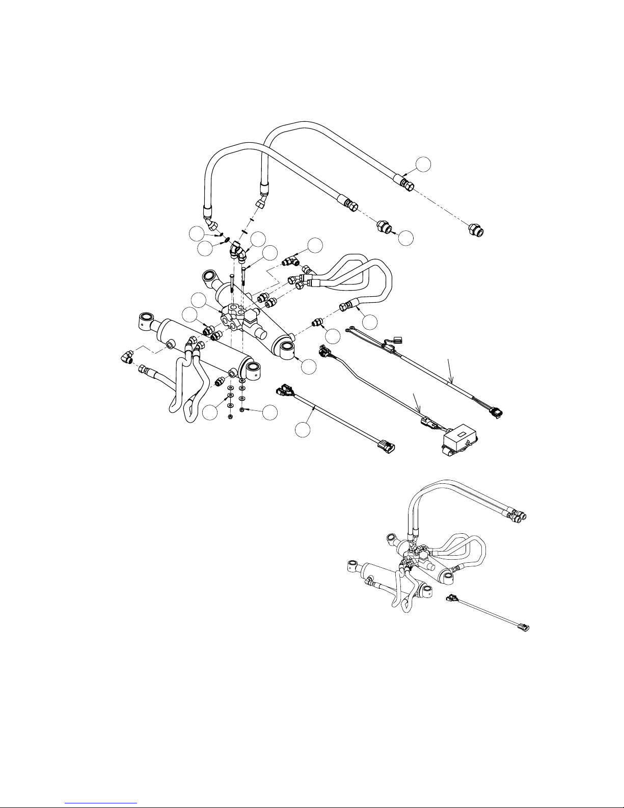
Hydraulic/Electric Hose Routings
HOSE ASSEMBLY
5
4
6
12
2
9 10
Item Part Qty Description
8
15
1
7
14
3
07-7733
13
07-7734
11
1. 03-2092 2 Elbow, 90º, 6MB-6MF
2. 03-2278 4 Fitting, 6MF-8MB
3. 03-3515 2 Fitting, 12MB-8MF
4. 03-3537 2 O-Ring, #8 Face Seal
5. 03-4912 2 Hose, .38 x 72, 8FF-8FF45, 100R2
6. 03-6074 2 Plate, Orice, #8, O-Ring Face Seal
7. 03-6244 4 Hose, .38 x 24, 6FF-6FF45, 3K
8. 03-6293 2 Fitting, Elbow, 45°, 8MB-8MF
9. 07-4032 6 Washer, Flat, Gr8, 1/4
10. 07-4033 2 Nut, Hex, nylock, 1/4-20, Gr8
11. 07-7737 1 Wire, Harness, 108 inches
12. 19687 1 Valve, Electro-Hydraulic Selector
13. 88921 2 Cylinder Assembly
14. LAF4229 2 Fitting, 6MB-6MF
15. RHW1043 2 Screw, HHC, .25-20 x 2.5, Gr8
32
Page 33
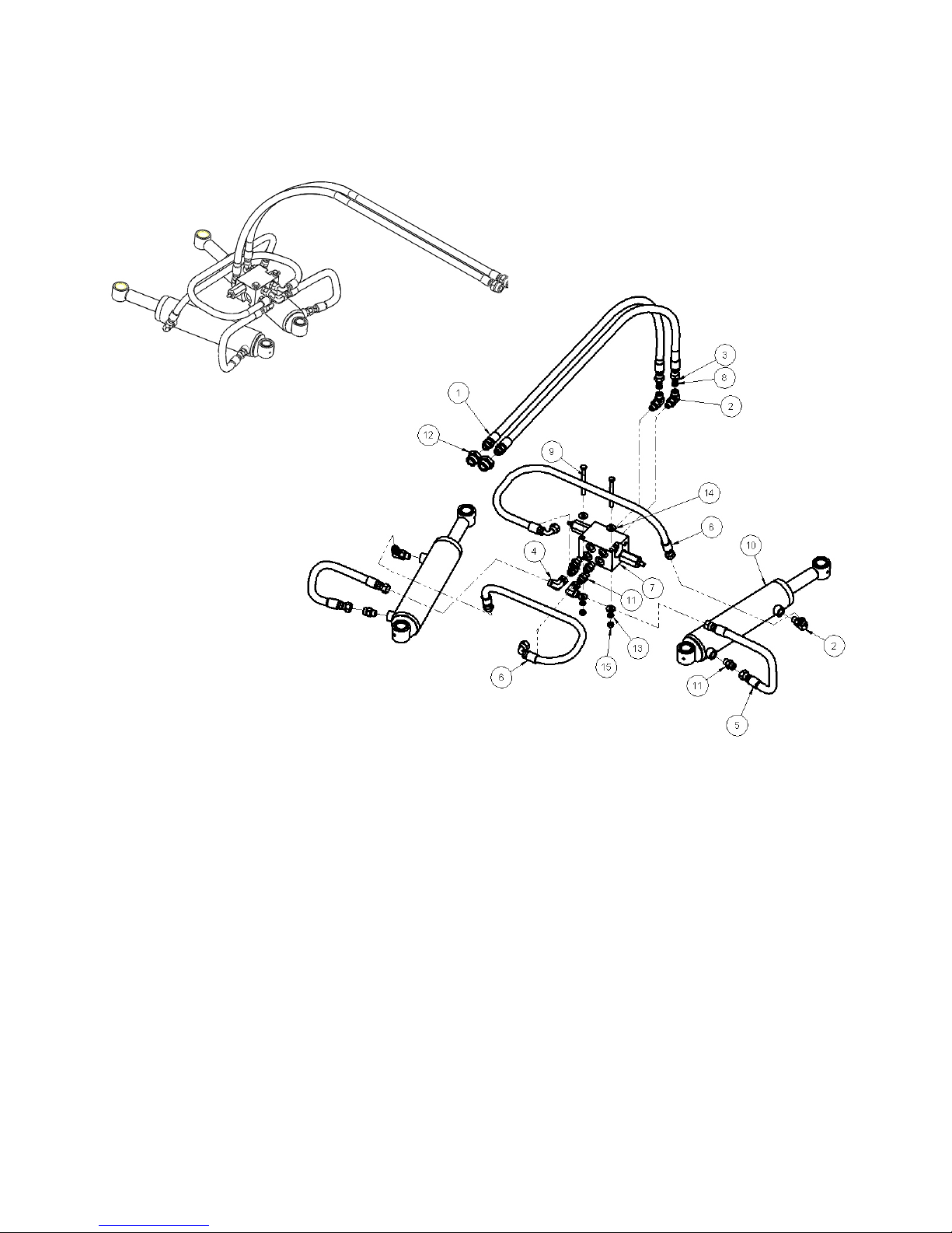
Hydraulic Hose Routings
HOSE ASSEMBLY
Item Part Qty Description
1. 03-10111 2 Hose, .38 x 78, 6FF-8MB, 100R2
2. 03-2092 4 Elbow, 90º, 6MB-6MF
3. 03-3573 2 O-Ring, Face Seal, 3/8, SAE #6
4. 03-3689 2 Elbow, 90º, 6FF-6MF
5. 03-4704 2 Hose, .38 x 27, 6FF-6FF, 3K
6. 03-5236 2 Hose, .38 x 42, 6FF-6FF90, 3K
7. 03-5903 1 Manifold
8. 03-6248 2 Plate, Hydraulic, Orice, #6 ORFS
9. 07-3652 2 Screw, HHC, Gr8, 5/16-18 x 3 1/2
10. 88921 2 Cylinder Assembly
11. LAF4229 6 Fitting, 6MB-6MF
12. LAF4271 2 Fitting, 8FB-12MB
13. P851105 2 Washer, Lock, 5/16
14. RHW5162 4 Washer, Flat, .31, Gr5
15. RHW7101 2 Nut, Hex, .31-18, Gr5
33
Page 34
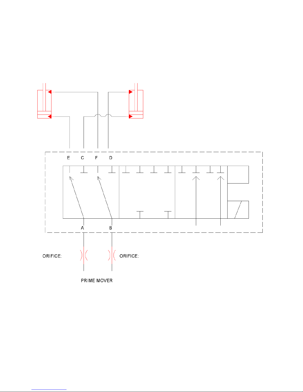
HYDRAULIC/ELECTRIC MANIFOLD SCHEMATIC
34
Page 35
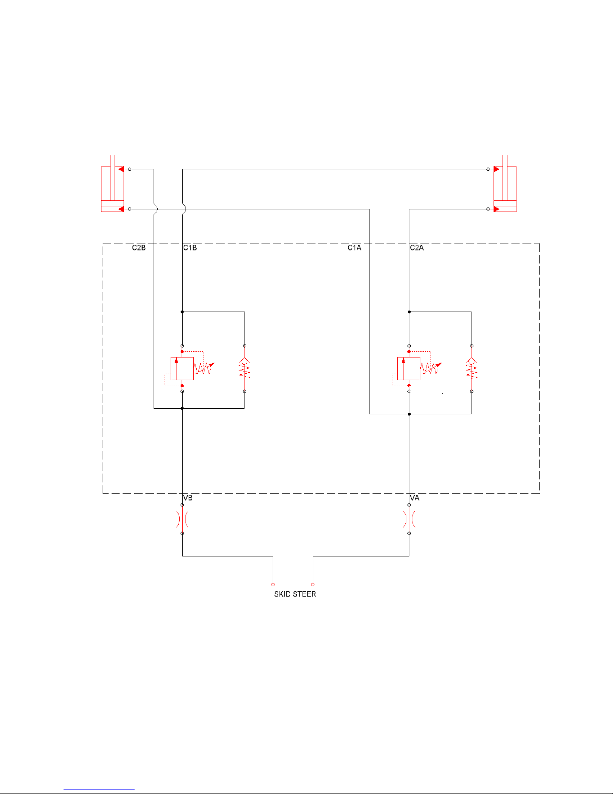
HYDRAULIC MANIFOLD SCHEMATIC
35
Page 36
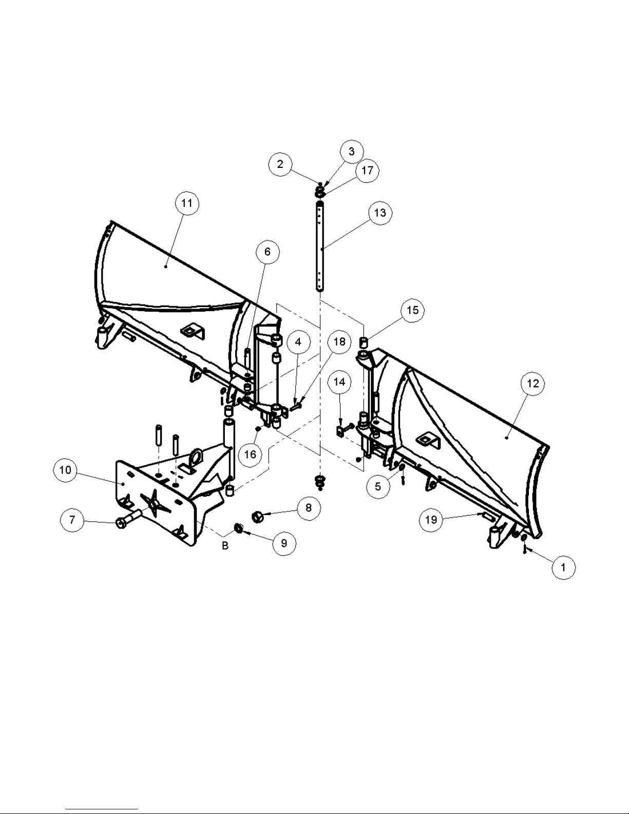
MOLDBOARD ASSEMBLY
36
Page 37

MOLDBOARD ASSEMBLY
Item Part Qty Description
1. 07-0206 6 Pin, Cotter, Gr2, 3/16 x 2 (5 ft)
07-0206 8 Pin, Cotter, Gr2, 3/16 x 2 (6,7,8,9,10 ft)
2. 07-0223 2 Fitting, Zerk, 1/8NPT
3. 07-3268 2 Snap Ring
4. 07-3674 2 Screw, HHC, Gr8, 1/2-13 x 2 3/4
5. 07-4090 6 Washer, 1 1/2 x 1 x .075 (5 ft)
07-4090 8 Washer, 1 1/2 x 1 x .075 (6,7,8,9,10 ft)
6. 07-6889 3 Pin, Clevis, 1 x 5, 4.7 Grip (5 ft)
07-6889 4 Pin, Clevis, 1 x 5, 4.7 Grip (6,7,8,9,10 ft)
7. 07-7838 1 Screw, HHC, Gr8, 1 1/2-6 x 6
8. 07-8083 1 Nut, Gr8, 1 1/2-6
9. 07-8084 1 Washer, Lock, Disk, 1 1/2
10. 13-17420 1 Pivoting Assembly
11. 13-17426-60 1 Weld, Left, Moldboard (5 ft)
13-17426-72 1 Weld, Left, Moldboard (6 ft)
13-17426-84 1 Weld, Left, Moldboard (7 ft)
13-17426-96 1 Weld, Left, Moldboard (8 ft)
13-17426-108 1 Weld, Left, Moldboard (9 ft)
13-17426-120 1 Weld, Left, Moldboard (10 ft)
12. 13-17430-60 1 Weld, Right, Moldboard (5 ft)
13-17430-72 1 Weld, Right, Moldboard (6 ft)
13-17430-84 1 Weld, Right, Moldboard (7 ft)
13-17430-96 1 Weld, Right, Moldboard (8 ft)
13-17430-108 1 Weld, Right, Moldboard (9 ft)
13-17430-120 1 Weld, Right, Moldboard (10 ft)
13. 13-17442 1 Shaft, 1.5 x 27.125
14. 13-17662 2 Plate, 3/8 x 2 x 3.5, with Hole
15. LAF9602 6 Spring Bushing/Bearing, 1.75 x 1/8 x 2
16. P158005 2 Nut, Nylock, 1/2-13
17. P855324 2 Bushing, Machine, 1-1/2 x 14ga
18. RHW5532 2 Washer, Flat, 9/16, Gr5
19. RHW8222 2 Pin, Clevis, 1 x 3 (5 ft)
RHW8222 4 Pin, Clevis, 1 x 3 (6,7,8,9,10 ft)
37
Page 38
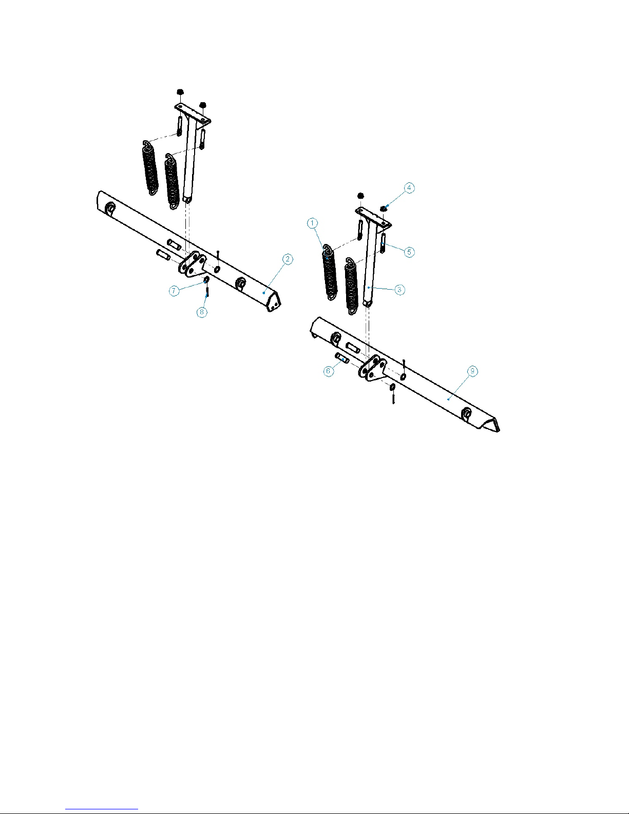
TRIP EDGE ASSEMBLY
Item Part Qty Description
1. LAF6405 4 Trip Spring, .393 x 14 x (26.25)
2. 13-17406-60 1 Weld, Left, Trip Edge (5 ft)
13-17406-72 1 Weld, Left, Trip Edge (6 ft)
13-17406-84 1 Weld, Left, Trip Edge (7 ft)
13-17406-96 1 Weld, Left, Trip Edge (8 ft)
13-17406-108 1 Weld, Left, Trip Edge (9 ft)
13-17406-120 1 Weld, Left, Trip Edge (10 ft)
3. 13-51846 2 Weld, Trip Spring Arm
4. RHW7607 4 Nut, Flange, Top Lock, .63-11, Gr8
5. RHW8065 4 Bolt, Spade, .62 x 3.25
6. RHW8222 4 Pin, Clevis, 1 x 3
7. 07-4090 4 Washer, 1 1/2 x 1 x .075
8. 07-0206 4 Pin, Cotter, Gr2, 3/16 x 2
9. 13-17411-60 1 Weld, Right, Trip Edge (5 ft)
13-17411-60 1 Weld, Right, Trip Edge (6 ft)
13-17411-60 1 Weld, Right, Trip Edge (7 ft)
13-17411-60 1 Weld, Right, Trip Edge (8 ft)
13-17411-60 1 Weld, Right, Trip Edge (9 ft)
13-17411-60 1 Weld, Right, Trip Edge (10 ft)
38
Page 39
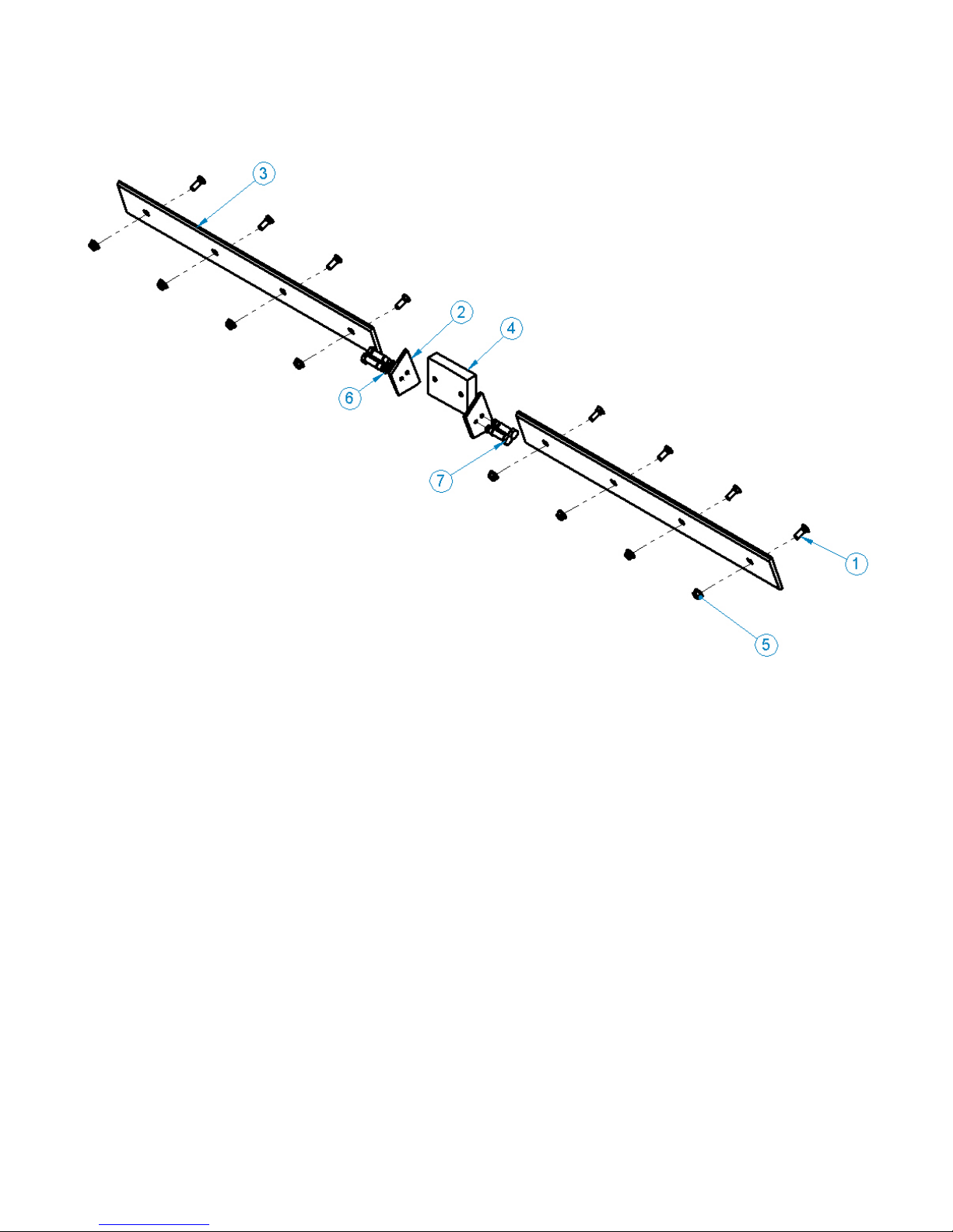
STEEL WEAR EDGE ASSEMBLY
Item Part Qty Description
1. RHW2663 4 Bolt, Plow, .63-11 x 1.75, Gr8 (5 ft)
RHW2663 6 Bolt, Plow, .63-11 x 1.75, Gr8 (6,7 ft)
RHW2663 8 Bolt, Plow, .63-11 x 1.75, Gr8 (8,9 ft)
RHW2663 10 Bolt, Plow, .63-11 x 1.75, Gr8 (10 ft)
2. 13-17488 2 Plate, 3/8 x 3.5 x 6.36
3. 13-17412-60 2 Wear Edge, 6 x .5 (5 ft)
13-17412-72 2 Wear Edge, 6 x .5 (6 ft)
13-17412-84 2 Wear Edge, 6 x .5 (7 ft)
13-17412-96 2 Wear Edge, 6 x .5 (8 ft)
13-17412-108 2 Wear Edge, 6 x .5 (9 ft)
13-17412-120 2 Wear Edge, 6 x .5 (10 ft)
4. 07-7837 1 Rubber, 6.9 x 5.5, with Holes
5. RHW7607 4 Nut, Flange, Top Lock, .63-11, Gr8 (5 ft)
RHW7607 6 Nut, Flange, Top Lock, .63-11, Gr8 (6, 7 ft)
RHW7607 8 Nut, Flange, Top Lock, .63-11, Gr8 (8, 9 ft)
RHW7607 10 Nut, Flange, Top Lock, .63-11, Gr8 (10 ft)
6. P851108 8 Washer, Lock, 1/2
7. P100804 4 Screw, HHC, 1/2-13 x 1, Gr5
39
Page 40
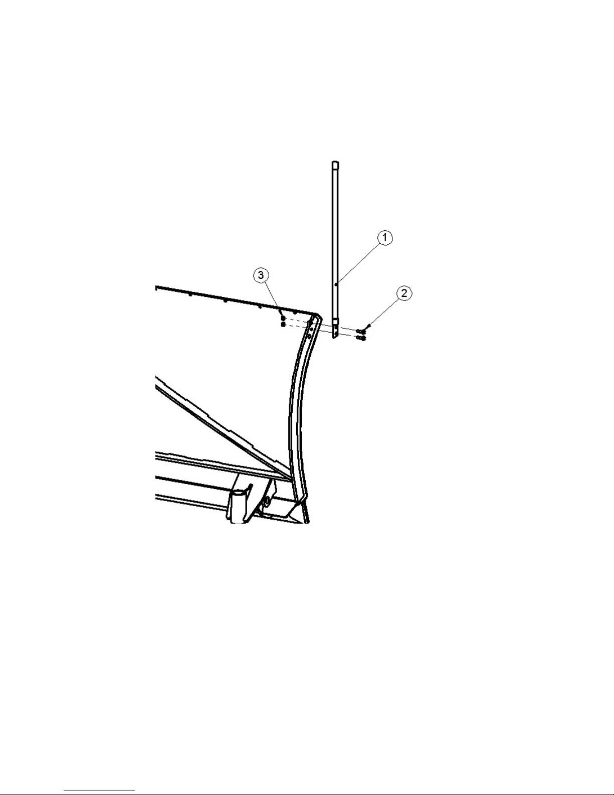
OPTIONAL MARKER KIT
Item Part Qty Description
1. 103006 2 Marker, Orange, 28 inches
2. RHW1105 4 Screw, HHC, Gr5, .31-18 x 1
3. RHW7103 4 Nut, Lock, Gr5, .31-18
40
Page 41

NOTES
41
Page 42
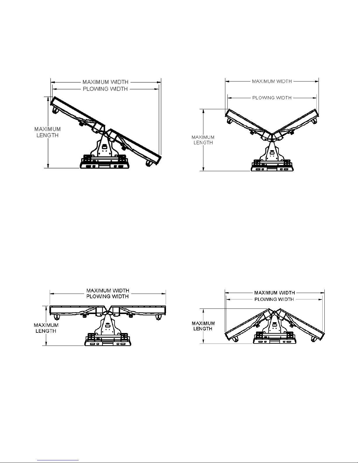
Specications and Model Views
PRODUCT SPECIFICATIONS
Angle Position
Straight Position
Scoop Position
“V” Position
42
Page 43
PRODUCT SPECIFICATIONS
60 inch 72 inch 84 inch 96 inch 108 inch 120 inch
Approximate Weight 865 lbs 920 lbs 975 lbs 1020 lbs 1060 lbs 1110 lbs
Approximate Weight 392 kg 417 kg 442 kg 463 kg 481 kg 503 kg
Maximum Width Straight Position 60 inches 72 inches 84 inches 96 inches 108 inches 120 inches
Plowing Width Straight Position 60 inches 72 inches 84 inches 96 inches 108 inches 120 inches
Maximum Length Straight Position 38 inches 38 inches 38 inches 38 inches 38 inches 38 inches
Maximum Width Scoop Position 54 inches 65 inches 75 inches 85 inches 95 inches 106 inches
Plowing Width Scoop Position 48 inches 58.5 inches 69 inches 79.5 inches 90 inches 100.5 inches
Maximum Length Scoop Position 43 inches 56 inches 59 inches 62 inches 65 inches 68 inches
Maximum Width “V” Position 58 inches 66 inches 76 inches 87 inches 97 inches 108 inches
Plowing Width “V” Position 56 inches 66.5 inches 77 inches 87.5 inches 98 inches 108 inches
Maximum Length “V” Position 36 inches 36 inches 36 inches 36 inches 36 inches 36 inches
Maximum Width Angled Position 55 inches 66 inches 76 inches 87 inches 97 inches 107 inches
Plowing Width Angled Position 52 inches 62.5 inches 73 inches 83.5 inches 94 inches 104 inches
Maximum Length Angled Position 43 inches 56 inches 59 inches 62 inches 65 inches 68 inches
Oscillation 5º
Tilt 5º
Blade Angle ±30º
Prime Mover Specications
DESCRIPTION SPECIFICATIONS
Weight of Primer Mover without Blade
Attachment
Hydraulic Pressure Output 3,500 psi Maximum
Rear Ballast As required to maintain full product stability. (Note the
13,230 lbs maximum
shipping weight on the product specication page, then
see the operator’s manual(s) for your primer mover,
loader and quick attach for your ballasting needs.)
43
Page 44
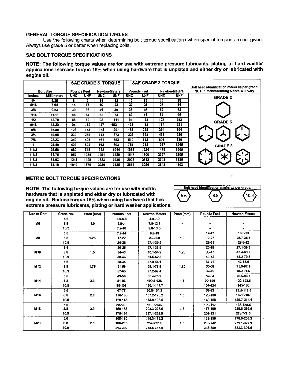
BOLT TORQUE SPECIFICATIONS
NOTE - Nylock nuts are utilized when greater resistance to vibrating loose is required, and greater operating
temperatures are not a factor. In addition, like lock nuts, nylock nuts have a safety feature that if the
bolt does vibrate loose, the nut will remain on the screw. Install nylock nuts to the standard torque
shown above.
44
Page 45

HYDRAULIC TORQUE SPECIFICATIONS
Face Seal: Assembly, Tube to Fitting
NOTICE - Face seal ttings have the most reliable sealing method and therefore,
should be used whenever possible.
Installation
1. Make sure threads and sealing surfaces are free of burrs, nicks, scratches, or foreign materials.
2. Install proper SAE O-ring to end of tting if not already installed. Ensure O-ring is fully seated and
retained properly.
3. Lubricate O-ring with a light coating of clean hydraulic oil.
4. Position tube and nut squarely on face seal of tting and tighten nut nger tight.
5. Using appropriate torquing device, tighten to given torque rating from the table below.
Torque Values
SAE Dash Size
-4 9/16-18 220 ± 10 18±1
-6 11/16-16 320 ± 25 27 ± 2
-8 13/16-16 480±25 40 ± 2
-10 1 - 14 750 ± 35 63±3
-12 13/16-12 1080±45 90 ± 4
-16 17/16-12 1440 ± 90 120±8
-20 111/16-12 1680±90 140±8
-24 2 - 12 1980±100 165±8
NOTE - ft-lb may be converted to Newton Meters by multiplying by 1.35582.
NOTE - in-lbs may be converted to Newton Meters by multiplying by 0.11298.
Tube Side
Thread Size
In-lbs Ft-lbs
45
Page 46
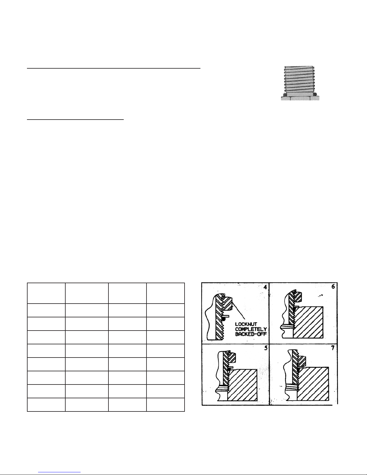
HYDRAULIC TORQUE SPECIFICATIONS
Straight Thread O-ring Fitting: Assembly, Fitting to Port
NOTE - Straight thread o-ring ttings are utilized to adapt hydraulic
systems to motors, pumps, cylinders, and valves.
Installation (Adjustable Fitting)
1. Make sure threads and sealing surfaces are free of burrs, nicks, scratches, or any foreign materials.
2. Install proper SAE O-ring on port end of tting if not already installed. Ensure O-ring is fully seated and
retained properly.
3. Lubricate O-ring with a light coating of clean hydraulic oil.
4. Back off nut as far as possible and push washer up as far as possible. (gure 4 & 5)
5. Screw tting into port. Hand tighten tting until backup washer contacts face of port. (gure 6)
6. To position the tting, unscrew to desired position, but not more than one full turn.
7. Hold tting in position with wrench. Using appropriate torquing device, tighten nut to given torque rating
from table. (gure 7)
Fitting
Size
-4 7/16 - 20 190 ± 10 16 ± 1
-6 9/16 - 18 420 ± 15 35 ± 1
-8 3/4 - 14 720 ± 25 60 ± 2
-10 7/8 - 14 1260 ± 50 105 ± 5
-12 1 1/16 - 12 1680 ± 75 140 ± 6
-16 1 5/16 - 12 2520 ± 100 210 ± 8
-20 1 5/8 - 12 3100 ± 150 260 ± 12
SAE Port
Thread Size
In-lbs Ft-lbs
-24 1 7/8 - 12 3800 ± 150 315 ±12
NOTE - ft-lb may be converted to Newton Meters by multiplying by 1.35582.
NOTE - in-lbs may be converted to Newton Meters by multiplying by 0.11298.
46
Page 47

WARRANTY
Limited Warranty
Except for the Excluded Products as described below, all new products are warranted to be free from defects
in material and/or workmanship during the Warranty Period, in accordance with and subject to the terms and
conditions of this Limited Warranty.
1. Excluded Products. The following products are excluded from this Limited Warranty:
(a) Any cable, part that engages with the ground (i.e. sprockets), digging chain, bearing, teeth, tamping
and/or demolition head, blade cutting edge, pilot bit, auger teeth and broom brush that either constitutes or is part
of a product.
(b) Any product, merchandise or component that, in the opinion of Paladin Light Construction1, has been
(i) misused; (ii) modi ed in any unauthorized manner; (iii) altered; (iv) damaged; (v) involved in an accident; or (vi)
repaired using parts not obtained through Paladin Light Construction.
2. Warranty Period. The Limited Warranty is provided only to those defects that occur during the Warranty
Period, which is the period that begins on the rst to occur of: (i) the date of initial purchase by an end-user, (ii) the
date the product is rst leased or rented, or (iii) the date that is six (6) months after the date of shipment by Paladin
Light Construction as evidenced by the invoiced shipment date (the “Commencement Date”) and ends on the date
that is twelve (12) months after the Commencement Date.
3. Terms and Conditions of Limited Warranty. The following terms and conditions apply to the Limited Warranty
hereby provided:
(a) Option to Repair or Replace. Paladin Light Construction shall have the option to repair or replace
the product.
(b) Timely Repair and Notice. In order to obtain the Limited Warranty, (i) the product must be repaired
within thirty (30) days from the date of failure, and (ii) a claim under the warranty must be submitted to Paladin Light
Construction in writing within thirty (30) days from the date of repair.
(c) Return of Defective Part or Product. If requested by Paladin Light Construction, the alleged
defective part or product shall be shipped to Paladin Light Construction at its manufacturing facility or other location
speci ed by Paladin Light Construction, with freight PRE-PAID by the claimant, to allow Paladin Light Construction
to inspect the part or product.
Claims that fail to comply with any of the above terms and conditions shall be denied.
LIMITATIONS AND EXCLUSIONS.
THIS LIMITED WARRANTY IS IN LIEU OF ALL OTHER WARRANTIES, EXPRESS OR IMPLIED, INCLUDING
WITHOUT LIMITATION THE WARRANTIES OF MERCHANTABILITY, FITNESS FOR A PARTICULAR PURPOSE
AND ANY WARRANTY BASED ON A COURSE OF DEALING OR USAGE OF TRADE.
IN NO EVENT SHALL PALADIN LIGHT CONSTRUCTION BE LIABLE FOR CONSEQUENTIAL OR SPECIAL
DAMAGES.
IN NO EVENT SHALL PALADIN LIGHT CONSTRUCTION BE LIABLE FOR ANY LOSS OR CLAIM IN AN
AMOUNT IN EXCESS OF THE PURCHASE PRICE, OR, AT THE OPTION OF PALADIN LIGHT CONSTRUCTION,
THE REPAIR OR REPLACEMENT, OF THE PARTICULAR PRODUCT ON WHICH ANY CLAIM OF LOSS OR
DAMAGE IS BASED. THIS LIMITATION OF LIABILITY APPLIES IRRESPECTIVE OF WHETHER THE CLAIM
IS BASED ON BREACH OF CONTRACT, BREACH OF WARRANTY, NEGLIGENCE OR OTHER CAUSE AND
WHETHER THE ALLEGED DEFECT IS DISCOVERABLE OR LATENT.
1
Attachment Technologies Inc., a subsidiary of Paladin Brands Holding, Inc. (PBHI) is referred to herein as Paladin Light
Construction.
February 10, 2010
47
 Loading...