

Page 1
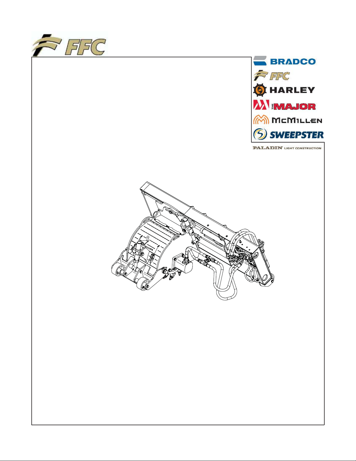
STANDARD FLOW
COLD PLANER
SERIAL NUMBER: ___________________ Manual Number: MR15650
Models: LAF5412 & LAF5413
MODEL NUMBER: ___________________ Release Date: January 30, 2006
800-747-2132 I www.paladinbrands.com 100 East Lee Road, Lee, IL 60530, United States of America
Page 2

Page 3

TABLE OF CONTENTS
Introduction, General Information, Serial Number ……………………………………………..1
Definitions of Safety Terms and Symbols ……………………………………………………… 2
Accident Prevention, Safety Instructions…………………………………………………… 3-4
Safety Signs…………………………………………………………………………………….5-6
Power Unit Specifications …………………………………………………………………………7
Mounting …………………………………………………………………………………………… 7
Hydraulic Connection……………………………………………………………………………… 7
Setup ………………………………………………………………………………………………. 8
Operation ……………………………………………………………………………………………9
Maintenance………………………………………………………………………………………..10
Service ……………………………………………………………………………………………...11
Parts Illustration……………………….……………………………………………………………12
Parts List ………………………………..……………………………………………………..….. 13-14
Cylinder Illustration & Parts List ………………………………………………………………….15
Specifications & Requirements……………………………………………………………………15
Warranty ……………………………………………………………………………………………. i
INTRODUCTION
Congratulations on your purchase of a new FFC Attachments Cold Planer. This product has been designed and built for
planing & milling asphalt. This product may also be used for roughing concrete. You or any other person who will be
assembling, operating, maintaining, or working with this product are required to read and completely understand the
information and instructions contained in this manual. If anyone does not fully understand every part of this manual,
please obtain further assistance by contacting the dealer from which this product was purchased or by contacting FFC
Attachments at the telephone number or address listed on the cover of this manual. Keep this manual available for
reference whenever this product is being handled or used. Provide this manual to any new owners and/or operators.
This manual covers model(s): LAF5412 & LAF5413
GENERAL INFORMATION
The purpose of this manual is to assist in assembling, mounting, operating, and maintaining your Planer: read this manual
carefully to obtain valuable information and instructions that will help you achieve years of safe and dependable service.
The illustrations and data used in this manual were current at the time of printing, but due to possible engineering and/or
production changes, this product may vary slightly in detail. FFC Attachments reserves the right to redesign and/or
change components as necessary without notification to anyone.
Throughout this manual, references may be made to:
Power Unit The engine-driven machine to which this product must be attached.
Right, Left, Front, Rear Directions that are determined in relation to the operator of the equipment when
seated in the normal operating position.
IMPORTANT
NOTICE
Precautions that must be followed to prevent damage to equipment.
Precautions that must be followed to prevent substandard performance.
SERIAL NUMBER LOCATION
Always refer to the model and serial number when ordering parts or requesting information from your dealer. The serial
number plate for this product is located on the upper left of your Planer.
Reference Information
Model Number
Serial Number
Date Purchased
Loader Make
Loader Model
Loader Serial #
1
Page 4

DEFINITION OF SAFETY TERMS AND SYMBOLS
Throughout this manual, the terms DANGER, WARNING, and CAUTION are used to indicate the degree of
hazard to personnel if proper safety procedures are not followed. These words will be used in conjunction with
the Safety Alert Symbol: a dark triangle containing a white exclamation mark.
The Safety Alert Symbol means:
ATTENTION! BECOME ALERT! YOUR SAFETY IS INVOLVED!
DANGER
WARNING
CAUTION
Indicates an imminently hazardous situation which, if not avoided,
WILL result in death or serious injury.
Indicates a potentially hazardous situation which, if not avoided,
could result in death or serious injury.
Indicates a potentially hazardous situation which, if not avoided,
may result in minor or moderate injury;
May also be used to alert against unsafe practices which may result in personal injury.
ACCIDENTS CAN BE PREVENTED WITH
YOUR HELP!
No accident prevention program can be successful
without the wholehearted cooperation of the person
who is directly responsible for the operation of the
equipment.
To read equipment accident reports from all over
the country is to be convinced that a large number
of accidents can be prevented only by operators
who consistently anticipate the results of their
actions and thus prevent accidents from ever
occurring. No power-driven equipment, whether it
is on the highway, in a farm field, or in an industrial
plant, can be any safer than the person who is at
the controls.
If accidents are to be prevented (and accidents can
be prevented), that prevention will come from
equipment operators who accept their complete
responsibility.
The designer, the manufacturer, and the safety
engineer all help create a safe product, but their
combined efforts can be wiped out with a single
careless act by the operator of that product.
OR
ARE THE KEY TO SAFETY BECAUSE:
YOU
YOU
are responsible for the SAFE operation and
maintenance of YOUR
are responsible to familiarize yourself, and
YOU
anyone else who will assemble, operate, maintain,
or work around this product, with the safety
information contained in this manual.
YOU
are responsible to read ALL information
contained in this manual to any operators or
maintenance personnel who are not fully able to
read the written English language. Whether YOU
read the manual as written or translate it into
another language, YOU
operators and maintenance personnel have a
complete understanding of the full and exact
contents of this manual. Translations of this
manual into other languages are available by
submitting a written request to FFC Attachments.
Planer.
must make certain that all
The best safety device is a careful operator. FFC
Attachments and your dealer ask that YOU
careful, responsible equipment operator.
be that
YOU
can reduce the risk of injury or death by
following all safety precautions and by using good
safety practices.
2
Page 5
SAFETY INSTRUCTIONS
WORK SAFELY - A CAREFUL OPERATOR IS THE BEST INSURANCE AGAINST ACCIDENTS !!
SECTION 1
WARNING SECTION
WARNING
Obey all the safety instructions listed in
this section and throughout this manual.
Failure to obey instructions in this
section could result in death or serious
injury.
BEFORE ATTEMPTING ANY TYPE OF ASSEMBLY,
OPERATION, MAINTENANCE, OR OTHER WORK ON
OR NEAR THIS PRODUCT:
x READ AND COMPLETELY UNDERSTAND THIS
MANUAL.
x READ AND COMPLETELY UNDERSTAND THE
MANUALS PROVIDED WITH YOUR POWER
UNIT, LOADER AND QUICK-ATTACH.
x Read and understand all safety signs on this
product and on your power unit, loader, and quickattach.
x Know all your controls and know how to quickly stop
all power unit movement, the planer movement, and
the engine in case of an emergency.
x Know and obey all applicable government rules,
O.S.H.A. regulations, local laws and other
professional guidelines for your operation.
x Make sure that anyone who will be assembling,
mounting, maintaining, repairing, removing, and/or
storing this product:
x has been instructed in the safe operation of this
product and
to which this product is attached.
x is physically and mentally capable of the safe
operation of this type of equipment.
x is not under the influence of drugs or alcohol.
x is carefully supervised from a safe distance,
especially if such person is inexperienced.
x wears appropriate protective equipment (i.e.
hardhat, safety glasses, work gloves, protective
shoes, respirator, ear protection, etc.).
x does not wear loose fitting clothing, loose or
uncovered hair, or any accessories (jewelry,
necktie, scarf, wrist watch, etc.) that can catch in
moving parts.
x has annually reviewed all safety instructions.
x Know and follow good work practices when
assembling, mounting, maintaining, repairing,
removing, and storing this product:
x Work on a level surface in a well lit area.
x Keep the area clean and dry.
x Use properly grounded electrical outlets & tools.
x Use the right tool for the job at hand.
x Make sure that your tools are in good condition for
performing the desired function.
of the power unit and quick-attach
x When using tools, wear the protective equipment
specified by the tool manufacturer. (i.e. hardhat,
safety glasses, work gloves, protective shoes, etc.)
WHEN YOUR POWER UNIT IS USED DURING ANY
TYPE OF ASSEMBLY, OPERATION, MAINTENANCE,
OR OTHER WORK ON OR NEAR THIS PRODUCT:
x Before leaving the operator’s station or before
beginning any type of work on this product, lower
this product to the ground, apply your power unit’s
parking brake, stop the engine, remove the starter
key, wait for all moving parts to stop, and then
relieve all pressure in the hydraulic lines. Refer to
your power unit’s operator’s manual for instructions
on how to relieve hydraulic pressure in lines.
x Know your loader’s safe lifting and operating
capacity and the weight of this product. See the
specifications in this manual for the weight of this
product and refer to your power unit’s and loader’s
operator’s manuals for safe operating limits. Lift
capacity may be reduced if using a quick-attach.
x Never allow anyone, except the operator, to be
around the power unit or this product when either is
in motion. Do not startup unless others are clear of
the work area.
x Do not allow riders on this product or the power unit.
x Do not stand or climb on this product when raised.
x Do not place any part of your body under any part of
this product unless this product is securely resting
on adequate blocking or on the ground.
x Do not use blocking made of concrete blocks, logs,
buckets, barrels or any other material that could
suddenly collapse or shift positions. Do not use
wood or steel blocking that shows any signs of
material decay. Do not use blocking that is warped,
twisted, or tapered.
x Never operate controls from the ground. Operate
the controls only from the operator’s station.
x Never leave equipment unattended with the engine
running or with this product raised on the loader.
x Be aware of the added weight and width of this
product. Reduce travel speeds accordingly,
especially when traveling over rough ground.
x Keep this product close to the ground and under
control when transporting.
3
Page 6
SAFETY INSTRUCTIONS
WORK SAFELY - A CAREFUL OPERATOR IS THE BEST INSURANCE AGAINST ACCIDENTS !!
WARNING SECTION [CONTINUED]
WARNING
Obey all the safety instructions
listed in this section and throughout
this manual. Failure to obey
instructions in this section could
result in death or serious injury.
WHEN DEALING WITH HYDRAULICS DURING ANY
TYPE OF ASSEMBLY, OPERATION, MAINTENANCE,
OR OTHER WORK ON OR NEAR THIS PRODUCT:
x Hydraulic fluid under pressure can penetrate the
skin and cause serious injury or death. Hydraulic
leaks under pressure may not be visible!
x If any fluid penetrates the skin, GET IMMEDIATE
MEDICAL ATTENTION!!
x Wear safety glasses, protective clothing, and use a
sound piece of cardboard or wood when searching
for hydraulic leaks. DO NOT USE YOUR HANDS!
x Before connecting or disconnecting hydraulic hoses,
read your tractor or power unit’s operator’s manual
for detailed instructions on connecting and
disconnecting hydraulic attachments.
x Make certain that all parts meet the specifications for
this product when installing or replacing hydraulic
hoses or fittings.
x After connecting hydraulic lines:
x Slowly and carefully raise the loader and cycle
the rollback / dump cylinders to check hose
clearances and to check for any interference.
x Operate the hydraulics on this product to check
hose clearances and to check for any
interference.
x Make certain that the hoses cannot interfere with
or actuate the quick-attach mechanism.
x Make certain that hoses will not be pinched, or get
tangled, in any equipment.
x Do not lock the auxiliary hydraulics of your power
unit in the “ON” position.
x Refer to your power unit’s operator’s manual and
this manual for procedures and intervals, then
inspect and maintain the entire hydraulic system to
insure that the fluid remains clean, that all devices
function properly, and that there are no fluid leaks.
WHEN MOUNTING THIS PRODUCT TO YOUR
POWER UNIT:
x Refer to the operator’s manuals of your power unit,
your loader, and your quick-attach for special or
detailed mounting instructions.
x This product should fit onto the quick-attach or
loader arms of your power unit the same as the
original products that were designed by your loader /
quick-attach manufacturer.
x If this product does not fit properly, contact FFC
Attachments before operating.
x Never place your finger into the mounting plate or 3-
point hitch or loader holes. A slight movement of the
power unit or this product could cause serious injury.
BEFORE EACH USE, THOROUGHLY INSPECT THIS
PRODUCT AND:
x Make certain that all safety signs are in place and
legible. Refer to the safety sign page in this manual
for the placement of safety signs for this product.
x Replace all damaged or excessively worn parts and
hardware only with genuine FFC Attachments parts
or with properly rated fasteners, hydraulic hoses, or
fittings.
x Make certain that all locking pins, latches, and
connection devices are properly installed and
secured.
x Make certain that all protective guards, canopies,
doors, etc., are in place and secure.
WHEN OPERATING THIS PRODUCT IN
ACCORDANCE WITH DESIGN INTENTIONS:
x Keep everyone at least nine feet away from the unit
when operating.
x Never operate your planer with the cover open.
WHEN ADJUSTING, SERVICING OR REPAIRING THIS
PRODUCT:
x Make no modifications to your planer.
x When making repairs, use only genuine FFC
Attachments parts or, for fasteners, hydraulic hoses,
or hydraulic fittings, use only properly rated parts.
x Replacement parts, for parts with safety signs
attached, must also have safety signs attached.
4
Page 7
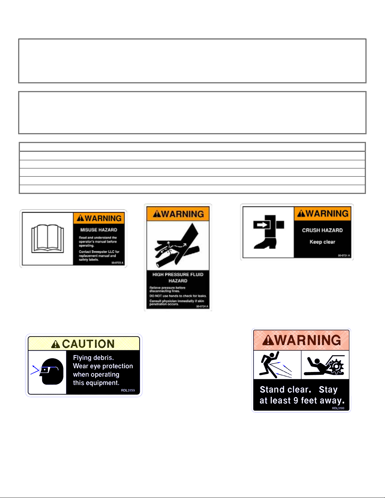
SAFETY SIGN LOCATIONS
INSTRUCTIONS
x Keep all safety signs clean and legible.
x Replace all missing, illegible, or damaged safety signs.
x Replacement parts for parts with safety signs attached must also have safety signs attached.
x Safety signs are available, free of charge, from your dealer or from FFC Attachments.
PLACEMENT OR REPLACEMENT OF SAFETY SIGNS
1. Clean the area of application with non-flammable solvent, then wash the same area with soap and water.
2. Allow the surface to fully dry.
3. Remove the backing from the safety sign, exposing the adhesive surface.
4. Apply the safety sign to the position shown in the diagram above and smooth out any bubbles.
ITEM QTY. PART # DESCRIPTION
1 1 50-0723 READ MANUAL
2 1 50-0724 HYDRAULIC
3 1 50-0721 CRUSH HAZARD
4 2 RDL3159 FLYING DEBRIS
5 2 RDL3100 STAND CLEAR
ITEM # 3
ITEM # 1
ITEM # 2
ITEM # 4
ITEM # 5
5
Page 8
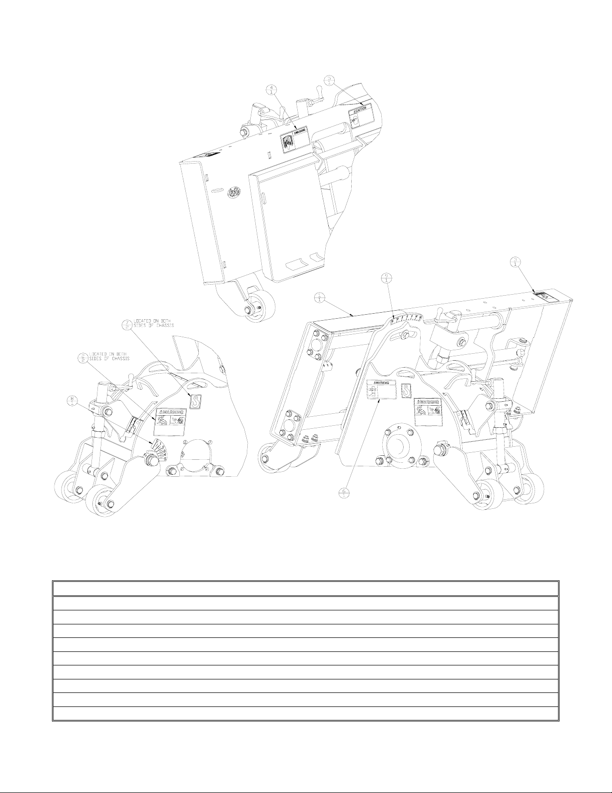
SAFETY SIGN LOCATIONS (CONTINUED)
DECAL PARTS LIST
ITEM QTY. PART # DESCRIPTION
1 1 LAF8231 NON-SKID TAPE
2 2 RDL3100 DECAL, WARNING ROTATING CUTTER
3 1 50-0724 DECAL, WARNING OIL INJ. HAZARD
4 1 50-0723 DECAL, WARNING READ MANUAL
5 1 RDL3159 DECAL, WARNING FLYING OBJECTS
6 1 50-0721 DECAL, WARNING CRUSHING HAZARD
7 2 RDL3179 DECAL, LIFT POINT
8 1 RDL3301 DECAL, DEPTH INDICATOR
9 1 RDL3302 DECAL, TILT INDICATOR
6
Page 9
POWER UNIT SPECIFICATIONS
IMPORTANT Exceeding any of the maximum recommended tractor or power unit specifications
CAN result in damage to this product and
WILL
void all FFC Attachments warranties.
DESCRIPTION SPECIFICATIONS
Weight of Power Unit without Planer 11,000 lbs. maximum
Operating Capacity of Power Unit’s loader 4,500 lbs. maximum
Lift Capacity of Power Unit’s loader 9,000 lbs. maximum
Hydraulic Pressure Output 3,400 psi. maximum
Front or Rear Ballast As required to maintain full power unit stability. (Note
the shipping weight on page 15, then see the operator’s
manual(s) for your power unit, loader, and quick-attach for
ballasting needs.)
PLANER MOUNTING
SAFETY FIRST!! READ AND UNDERSTAND THE SAFETY INSTRUCTIONS (pages 2-4 of this
manual) BEFORE BEGINNING ANY PLANER MOUNTING
1. Place this product on a firm, level surface that is large enough to safely accommodate this product, your
power unit and all workers involved in the mounting process.
2. Refer to the operator’s manual(s) for your power unit, loader, and quick-attach and follow the mounting
instructions contained therein.
3. Carefully raise the loader and cycle the tilt cylinders to check clearances and to verify that all mounting
procedures have been successfully completed.
IMPORTANT Lubricate all grease fittings before connecting this product to your power unit’s hydraulic
system. Refer to PLANER MAINTENANCE on page 10 and follow the instructions.
PLANER HYDRAULIC CONNECTION
SAFETY FIRST!! READ AND UNDERSTAND THE SAFETY INSTRUCTIONS (pages 2-4 of this
manual) BEFORE BEGINNING ANY PLANER HYDRAULIC CONNECTION
1. Disconnect the hydraulic hose quick couplers from one another and attach the quick couplers to your
power unit as per the instructions in your power unit’s operator’s manual.
2. Carefully raise the loader and cycle the tilt cylinders to check hose clearances and to check for any
interference.
3. Cycle the hydraulic cylinder(s) on this product several times from fully retracted to fully extended until all air
has been completely removed from the cylinder.
NOTICE: When shipped, the hydraulic cylinder on this product contained air or an air-fluid mixture.
Failure to remove all the air from the hydraulic cylinder can cause uneven, jerky cylinder movement
when the hydraulic controls are being operated and unwanted cylinder movement when those controls
are not being operated.
WARNING
Do not lock the auxiliary hydraulics of your tractor or power unit in the “ON”
position. Failure to obey this warning could result in death or serious injury.
7
Page 10
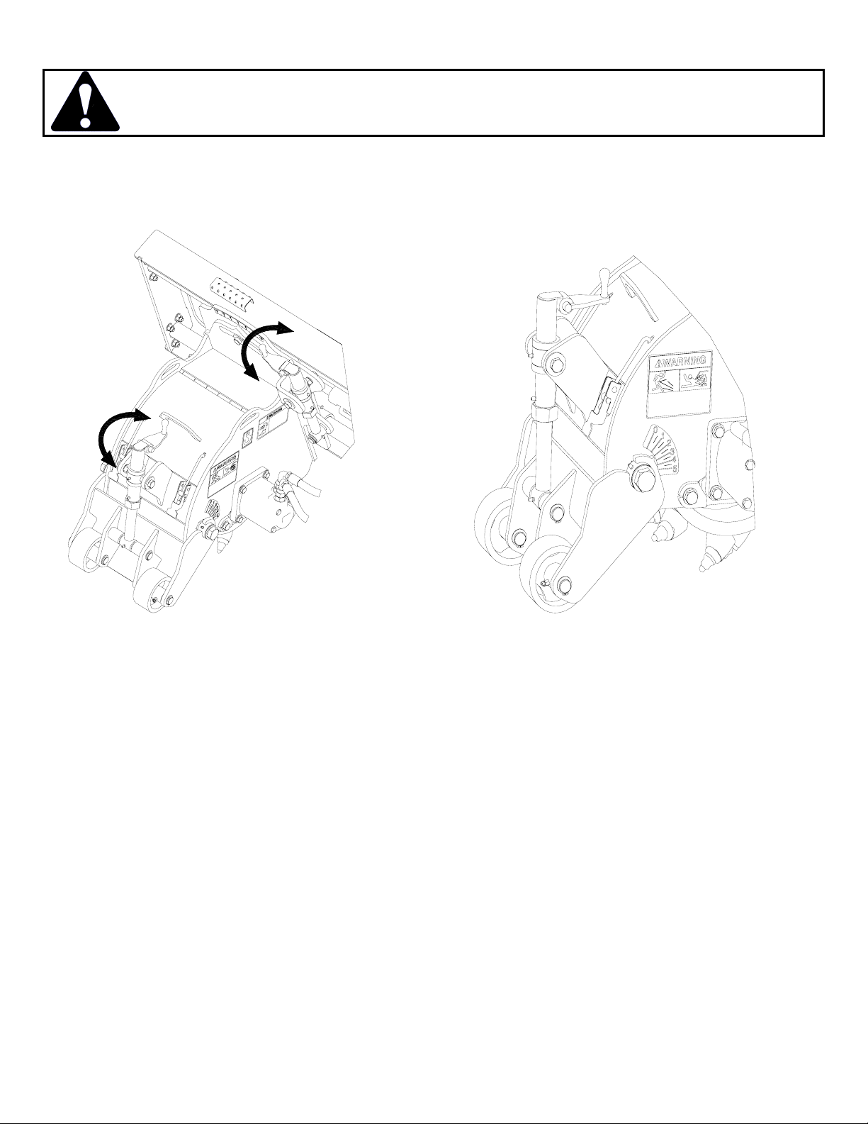
PLANER SETUP
SAFETY FIRST!! READ AND UNDERSTAND THE SAFETY INSTRUCTIONS (pages 2-4 of this
manual) BEFORE BEGINNING ANY PLANER SETUP
Setting planer depth:
i Turn the depth jack (located on the front of the planer) to adjust planing depth.
i A depth indicator decal is located on the left side of the chassis.
Setting planer sideshift:
i To sideshift the planer, actuate the diverter valve (LAF4699). The diverter valve is bi-directional.
i Actuate the hydraulic system of the power unit and the planer will sideshift.
i Return the diverter valve to its original position after sideshift operation is completed.
Setting planer Tilt:
i The planer tilt can be adjusted using the tilt jack located on the left side of the chassis.
i An indicator decal is provided to set the tilt at an approximate angle.
8
Page 11
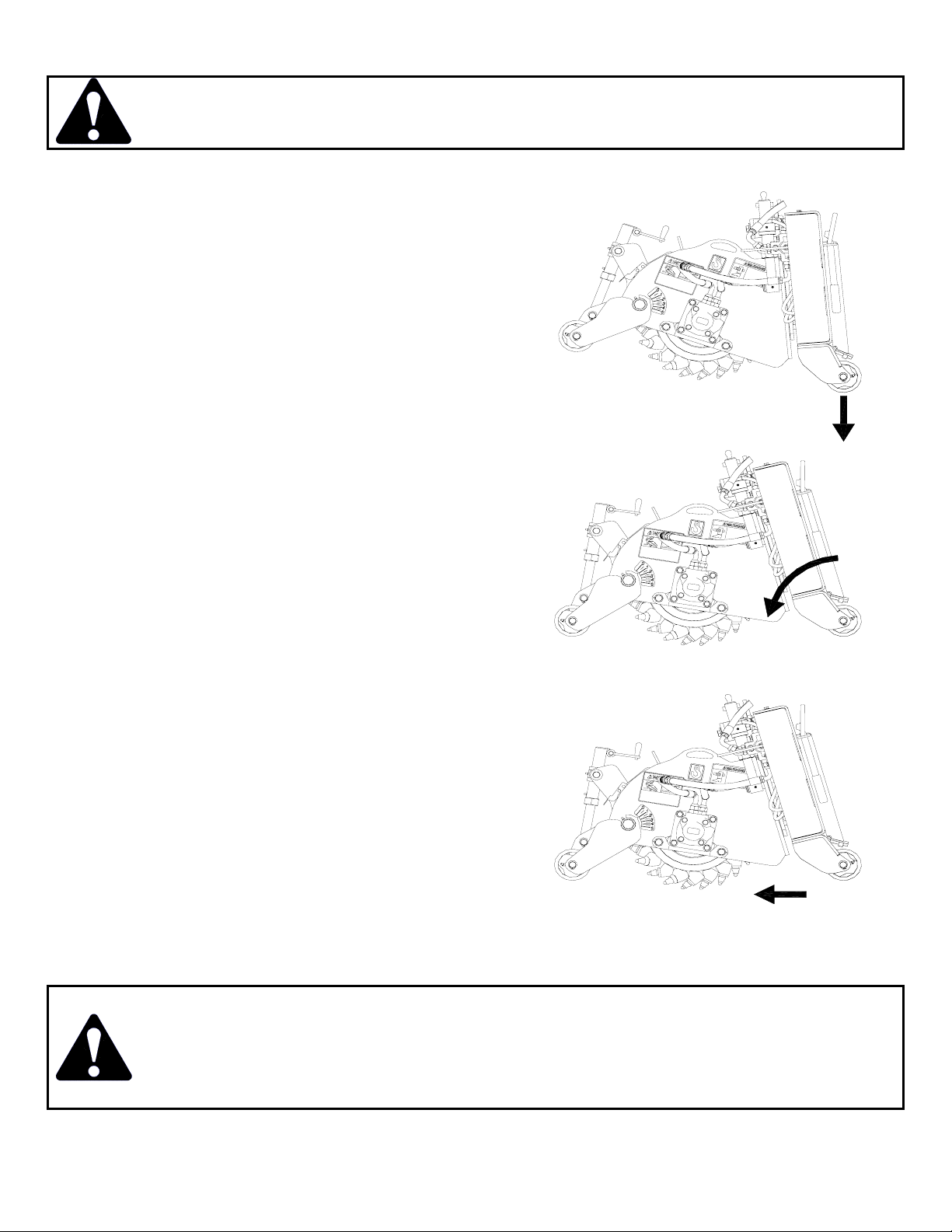
PLANER OPERATION
SAFETY FIRST!! READ AND UNDERSTAND THE SAFETY INSTRUCTIONS (pages 2-4 of this
manual) BEFORE BEGINNING ANY PLANER OPERATION
Starting a Cut:
1. To begin a cut, adjust the tilt and depth jacks to
the desired tilt depth with the planer slightly
above the ground. Engage the hydraulic system
to start the drum.
2. Lower the planer, bringing the rear planer
wheels onto the ground
3. Roll the planer into the cut, until the front
wheels of the planer are on the ground.
4. Slightly lift the front loader wheels to create a
downward force on the planer. Slowly move
forward, planing in a straight line.
NOTE: Materials can vary greatly: it is recommended that cutting depth be limited to 1 inch when roughing
concrete.
WARNING
Failure to obey the following procedures could result in death or serious injury:
x Never lift this product above (a.) the operator’s eye level or (b.) to a height where
visibility is obstructed, whichever is lower.
x Never operate your Planer with the Cover open.
9
Page 12
PLANER MAINTENANCE
SAFETY FIRST!! READ AND UNDERSTAND THE SAFETY INSTRUCTIONS (pages 2-4 of this
manual) BEFORE BEGINNING ANY PLANER MAINTENANCE
WARNING
Failure to obey the following procedures could result in death or serious injury.
x Never walk under or climb on raised liftarms or a raised attachment.
x If the attachment must be raised, block the machine with blocks or jackstands, NOT lift
jacks or hoists.
WARNING
Failure to obey the following procedures could result in death or serious injury.
x Always wear protective equipment including a HARD HAT and EYE PROTECTION when
operating, performing maintenance, or working near this product.
BEFORE EACH USE
x Make sure that all nuts and bolts are in place and properly tightened.
x Make sure that all other fasteners are in place and are performing their specified function.
x Make sure that all hydraulic fittings are tightened to specifications and that there are no leaks in any fittings
or hoses. (see the hydraulic connection section on page 7.)
x Make sure that all safety signs are in place, are clean, and are legible.
(see the safety sign section on pages 5-6)
x Replace any damaged parts and excessively worn parts.
DAILY
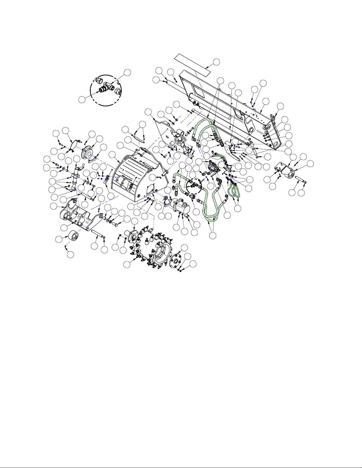
x Grease [9] fittings: [1] on the drum shaft bearing / [4] on the wheels / and [4] on the slider bar bosses (see
parts illustration on page 12).
NOTE: Lubricate all grease fittings with a NLGI #1 or 2 multipurpose grease.
WEEKLY
x Grease [8] fittings: [2] on the depth jack / [1] on the depth pin / [2] on the depth weldment / [2] on the tilt
jack / and [1] on the tilt pin (see parts illustration on page 12).
NOTE: Lubricate all grease fittings with a NLGI #1 or 2 multipurpose grease.
10
Page 13
PLANER SERVICE
SAFETY FIRST!! READ AND UNDERSTAND THE SAFETY INSTRUCTIONS (pages 2-4 of this
manual) BEFORE BEGINNING ANY PLANER SERVICE
1. Park your power unit on a level surface with this product properly attached.
2. Place your power unit’s transmission in “Park” and engage the parking brake.
3. Lower this product onto preplaced blocking.
4. Shut off your power unit’s engine, remove the starter key, wait for all moving parts to come to a stop, and relieve all
pressure in the hydraulic lines.
WARNING
Do not use blocking made of concrete blocks, logs, buckets, barrels or any other material
that could suddenly collapse or shift positions. Do not use wood or steel blocking that
shows any signs of material decay. Do not use blocking that is warped, twisted, or tapered.
Failure to obey this warning could result in death or serious injury.
Pick Removal/Replacement:
Proper pick maintenance is essential to the productive use of your planer. Failure to perform regular pick maintenance
can result in severely decreased performance and expensive repairs to your planer drum.
A missing pick must be replaced immediately, as a missing pick will cause the surrounding picks to wear faster.
Picks must be replaced when their carbide tips become excessively blunt.
Picks must rotate freely in their holders. If picks do not rotate freely, they will develop flat spots. Picks should be removed
and retaining rings cleaned as necessary.
NOTE: the edge picks wear faster and require more frequent replacement.
CAUTION
Picks become hot during operation: Wait for picks to cool before replacing.
Do not hammer on carbide point when replacing picks. The carbide can break and cause
injury.
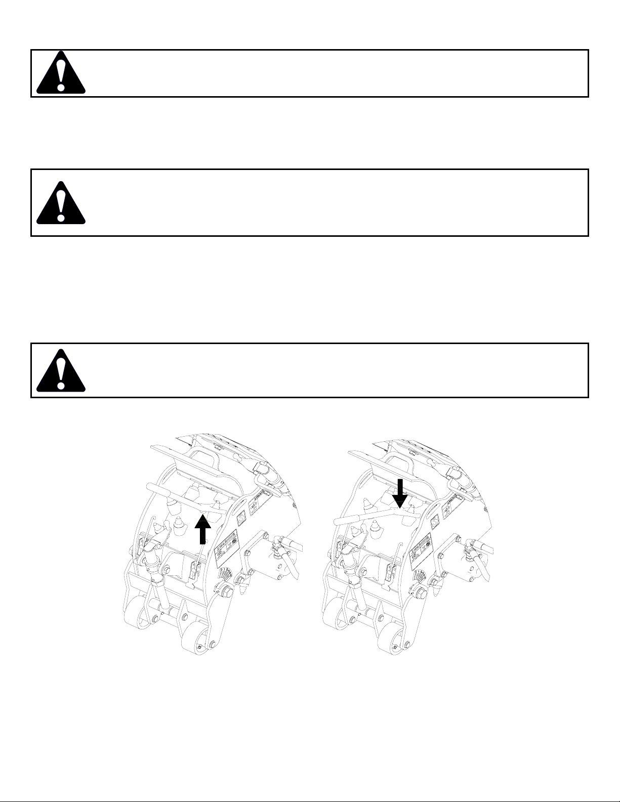
Remove and replace picks using the pick removal tool (LAF9326) and a hammer as shown below.
NOTE: the edge picks wear faster and require more frequent replacement.
NOTE: do not hammer on carbide point of the pick. The carbide can break and cause injury.
11
Page 14
64
STANDARD FLOW COLD PLANER PARTS ILLUSTRATION
19
1
48
51
42
59
72
59
15
75
68
13
8
38
76
71
2
64
24
5
4
73
18
14
12
16
17
47
55
54
55
3
10
A
12
9
56
63
27
57
70
50
6
7
11
62
54
45
55
46
31
37
69
63
56
67
36
35
32
74
33
76
76
61
66
56
3
49
6
14
58
29
64
30
77
76
51
DETAIL A
43
23
20
60
70
44
59
52
65
53
57
28
40
50
63
56
51
76
73
59
34
21
24
26
76
33
74
22
24
26
59
73
25
41
77
54
64
76
51
73
39
76
12
Page 15

STANDARD FLOW COLD PLANER PARTS LIST
r
r
r
r
r
STANDARD FLOW COLD PLANER PARTS LIST
ITEM
No. QTY.
1 2 13-50392 13-50392 Rod, 2 x 47.25" w/ 0.406 Cross Hole
2 6 LAF4076 LAF4076 Hydraulic Fitting 12MFS 12MB Straight
3 6 LAF4229 LAF4229 Hydraulic Fitting 6MFS 6MB Straight
4 1 Hydraulic Quick Coupler, Female
5 1 Hydraulic Quick Coupler, Male
6 2 LAF4694 LAF4694 Hydraulic Tee 12MFS 12FFS 12MFS
7 1 LAF4697 LAF4697 Motor, 24 Cu. In.
8 1 LAF4698 LAF4698 Sideshift Cylinde
9 1 LAF4699 LAF4699 Two Position Diverter Valve
10 1 LAF4700 LAF4700 Cylinder Lock Valve
11 2 LAF4701 LAF4701 Hydraulic Hose, 5/8” dia., 12FFS-12FFS90, 36" Length
12 4 LAF4702 LAF4702 Hydraulic Hose, 1/4” dia., 6FFS-6FFS90, 22" Length
13 2 LAF4703 LAF4703 Hydraulic Hose, 5/8” dia., 12FFS-12FFS90, 60" Length
14 1 LAF4707 LAF4707 Check Valve
15 1 LAF4717 LAF4717 Key, Char Lynn 4K Moto
16 2 LAF4720 LAF4720 Hydraulic Fitting 12MB 6MFS Straight
17 2 LAF4721 LAF4721 Hydraulic Fitting 12MB 12MFS 45q
18 2 LAF4722 LAF4722 Hydraulic Hose, 5/8” dia., 12FFS-12FFS, 12" Length
19 1 LAF8231 LAF8231 Non-Skid Tape 4" x 24"
20 1 LAF9300 LAF9301 Chassis Weldment
21 1 LAF9302 LAF9303 Depth Arm Weldment
22 2 LAF9304 LAF9304 Jack Body Weldment
23 2 LAF9307 LAF9307 Lid Latch
24 4 LAF9309 LAF9309 Boss Pivot Bolt Space
25 1 LAF9310 LAF9310 Deadshaft Bearing
26 1 LAF9311 LAF9311 1” x 7.4” Dual Snap Ring Pin
27 1 LAF9313 LAF9313 Hub Weldment
28 1 LAF9314 LAF9315 Drum Assembly
29 1 LAF9316 LAF9316 Deadshaft Weldment
30 1 LAF9317 LAF9318 Sideshift Weldment
31 1 LAF9319 LAF9319 Mainframe Weldment
32 2 LAF9321 LAF9321 Wheel Bracket Weldment
33 4 LAF9322 LAF9322 Planer Wheel Weldment
34 2 LAF9323 LAF9323 Jack Screw Weldment
35 2 LAF9324 LAF9324 Dual Snap Ring Pin 1” x 5-29/32”
36 1 LAF9325 LAF9325 Dual Snap Ring Pin 1” x 5-17/32”
37 1 LAF9326 LAF9326 Pick Removal Tool
38 1 LAF9335 LAF9335 Valve Mounting Bracket
39 2 LAF9324 (5-29/32") LAF9347 (7-29/32") Dual Snap Ring Pin 1” x Length Noted
40 1 LAF9348 LAF9348 Bearing Guard
41 2 LAF9362 LAF9362 Bearing Mount Space
42 2 LAF9363 LAF9363 Bearing Mount Plate
43 2 LAF9386 LAF9386 Pivot Bushing
44 2 LAF9399 LAF9399 Water Kit Hole Cove
45 2 RHW1011 RHW1011 Grade 5 Hex Head Cap Screw, ¼” x 2”
46 2 RHW1207 RHW1207 Grade 5 Hex Head Cap Screw, 3/8” x 1-1/4””
47 2 RHW1215 RHW1215 Grade 5 Hex Head Cap Screw, 3/8” x 3”
48 2 RHW1217 RHW1217 Grade 5 Hex Head Cap Screw, 3/8” x 3-1/2”
49 6 RHW1406 RHW1406 Grade 5 Hex Head Cap Screw, ½” x 1-3/4”
50 8 RHW1407 RHW1407 Grade 5 Hex Head Cap Screw, ½” x 2”
51 8 RHW1601 RHW1601 Grade 5 Hex Head Cap Screw, 5/8” x 1-1/4”
LAF5412
12"
Contact FFC to obtain the correct item
Contact FFC to obtain the correct item
LAF5413
16" DESCRIPTION
13
Page 16

STANDARD FLOW COLD PLANER PARTS LIST (cont.)
ITEM
No. QTY.
52 3 RHW1604 RHW1604 Grade 5 Hex Head Cap Screw, 5/8” x 2”
53 2 RHW1908 RHW1908 Grade 5 Hex Head Cap Screw, 1” x 2-1/2”
54 8 RHW5062 RHW5062 Grade 5 Flat Washer USS, ¼”
55 8 RHW5232 RHW5232 Grade 5 Flat Washer SAE, 3/8”
56 20 RHW5432 RHW5432 Grade 5 Flat Washer SAE, ½”
57 10 RHW5532 RHW5532 Grade 5 Flat Washer SAE, 9/16”
58 4 RHW5632 RHW5632 Grade 5 Flat Washer SAE, 5/8”
59 10 RHW5662 RHW5662 Grade 5 Flat Washer USS, 5/8”
60 2 RHW5932 RHW5932 Grade 5 Flat Washer SAE, 1”
61 2 RHW6002 RHW6002 Grade 5 Lockwasher, 1/4”
62 4 RHW6202 RHW6202 Grade 5 Lockwasher, 3/8”
63 14 RHW6402 RHW6402 Grade 5 Lockwasher, 1/2”
64 8 RHW6602 RHW6602 Grade 5 Lockwasher, 5/8”
65 2 RHW6902 RHW6902 Grade 5 Lockwasher, 1”
66 2 RHW7001 RHW7001 Grade 5 Hex Nut, ¼”
67 4 RHW7201 RHW7201 Grade 5 Hex Nut, 3/8”
68 2 RHW7203 RHW7203 Grade 5 Lock Nut Center Dent, 3/8”
69 6 RHW7451 RHW7451 Grade 8 Hex Nut, 1/2”
70 10 RHW7502 RHW7502 Grade 8 Hex Nut, 9/16”
71 3 RHW7607 RHW7607 Grade 8 Top Lock Flange Nut, 5/8"
72 1 RHW7906 RHW7906 Castle Nut, 1-1/4” 18 tpi
73 13 RHW8090 RHW8090 Grease Zerk, ¼”–28 tpi, Straight
74 4 RHW8107 RHW8107 Grease Zerk, ¼”–28 tpi, 45 q
75 1 RHW8138 RHW8138 Cotter Pin, 5/32” x 2-3/4”
76 14 RHW8146 RHW8146 Retaining Ring, 1”, Heavy Duty
77 8 RHW9004 RHW9004 Self Tapping Screw, ¼” x ¾”
LAF5412
12"
LAF5413
16" DESCRIPTION
14
Page 17
CYLINDER ILLUSTRATION & PARTS LIST
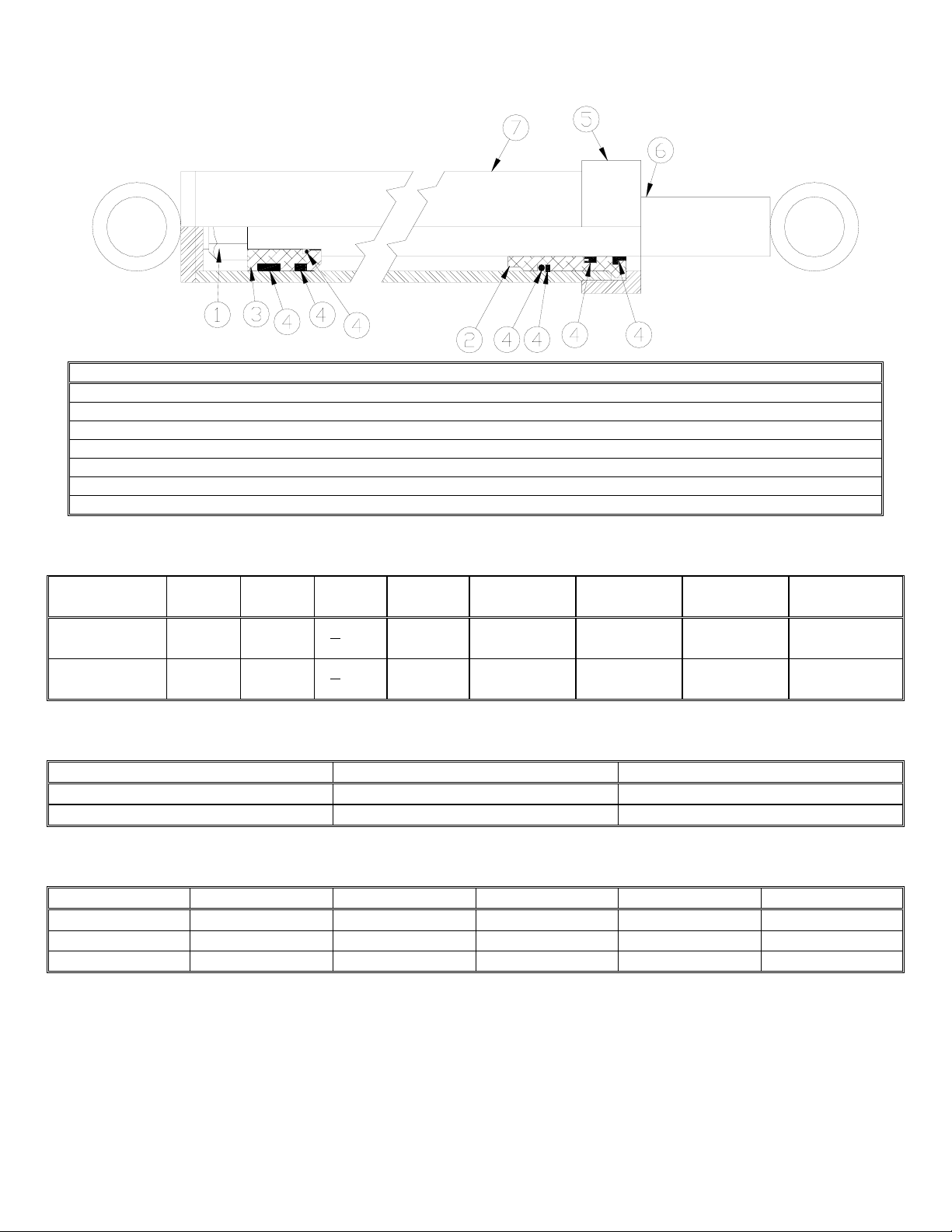
ITEM # Qty Part # DESCRIPTION
1 1 LAF4723 NUT, ¾-16 GRADE C ANTIVIBRATION
2 1 LAF4724 HEAD, 1.0” I.D. NOMINAL
3 1 LAF4725 PISTON 1.5” O.D. X 1” I.D. NOMINAL
4 1 LAF4726 SEAL KIT 1.5” BORE 1.0” ROD
5 1 LAF4727 COLLAR, 1.0 I.D. NOMINAL
6 1 LAF4728 SHAFT, 1” DIAMETER 24” STROKE
7 1 LAF4729 BARREL, 1.5” I.D. 24” STROKE
PLANER SPECIFICATIONS
Model
Number
LAF5412
Cutting
Width
Cutting
Depth
12” 0 – 5”
Tilt Sideshift Overall
Width
+
15q
24” 66” 33” 60” 1033 lbs
Overall
Height
Overall
Depth
Shipping
Weight
SSP12 LF
LAF5413
16 0 – 5”
+
15q
24” 66” 33” 60” 1116 lbs
SSP16 LF
PLANER REQUIREMENTS
Model Number Required Pressure Required Flow
LAF5412 SSP12 LF 2200 psi 13 gpm
LAF5413 SSP16 LF 2200 psi 16 gpm
TORQUE SPECIFICATIONS FOR STANDARD MACHINE HARDWARE
Bolt Size SAE Grade Bolt Torque Ft./Lbs Bolt Size SAE Grade Bolt Torque Ft./Lbs
0.31 - 18 5 17 0.56 - 11 5 120
0.38 - 16 5 30 0.63 - 11 5 150
0.50 - 13 5 75 1.00 - 8 5 580
15
Page 18

PLEASE TRI-FOLD AND AFFIX TAPE HERE
Warranty Registration Form and Delivery Inspection Report
IMPORTANT! Warranty Void if card is not returned with 10 days.
All Applicable sections must be filled in.
This section to be filled out and signed by Dealer at time of delivery.
Warranty Registration
Customer’s Name Dealer’s Name
Address Address
City State Zip City State Zip
Phone CHECK ONE:
Loader / Tractor Model Construction Use
Delivery Date Agricultural Use
Model or Part # Landscape Use
Serial # Other:
Dealer Inspection (check items applicable)
All Decals installed (see operator’s manual) Review Operating and Safety Instructions
Hydraulic fittings tight and free of leaks Guards and covers in place and secure
Fasteners tight Does Product Function Properly
I have thoroughly instructed the buyer on the above described equipment. This review included: The Operator’s manual content,
equipment care, adjustments, safe operation and applicable warranty policy.
Date Dealer’s Rep. signature
This section to be completed and signed by the customer
123 4 5
Excellent Good Average Unsatisfactory Poor
QUALITY ASSURANCE RATING
Question: FFC Local Dealer
Quality of Product: Appearance . . . . . . . . . . . . . . . . . . . . . . . . .
Construction . . . . . . . . . . . . . . . . . . . . . . . . .
Quality of Service . . . . . . . . . . . . . . . . . . . . . . . . . . . . . . . . . . . .
Value (Priced Fairly) . . . . . . . . . . . . . . . . . . . . . . . . . . . . . . . . . .
Does it perform as claimed . . . . . . . . . . . . . . . . . . . . . . . . . . . . .
The above described equipment and Operator’s Manual have been received by me and I have been thoroughly instructed
as to care, adjustments, safe operation and applicable warranty policy.
Date: Owner’s signature
NOTE! Make one copy each for the dealer’s and owner’s records. Mail original to FFC Attachments.
Form MR00000-000 Rev. 09/04
FFC Attachments • 100 E. Lee Road • PO Box 122 • Lee, IL 60530 • 800-747-2132 • Fax 815-824-2071
www.ffcattachments.com
Page 19

FFC LIMITED 12 MONTH WARRANTY
Thank you for purchasing a FFC product. Warranty protection is valid only when this Warranty
Registration is completed and signed by the customer and dealer, and mailed to FFC. I hereby
acknowledge that I have received a copy of the owners Limited Warranty and I accept the terms
therein.
For a period of 12 months from date of delivery of product to the original user, FFC, warrants
each product to be free from manufacturing defects, subject to the limitations contained in this
policy.
This warranty does not apply to defect caused, in whole or in part, by unreasonable use while in
the possession of the user, including, but not limited to: failure to properly set up product; failure
to provide reasonable and necessary maintenance; normal wear; routine tune ups or
adjustments; improper handling or accidents; operation at speed or load conditions contrary to
published specification; improper or insufficient lubrication; improper storage. This warranty is
also not a guarantee that the performance of each product will meet the expectations of the
purchaser.
FFC shall not be liable for consequential damages of any kind, including, but not limited to:
consequential labor costs or transportation charges in connection with the replacement or repair
of defective parts; lost time or expense which may have accrued because of said defects. In no
event shall FFC, Inc.’s total liability hereunder exceed the product purchase price.
FFC makes no warranty with respect to trade accessories or any component or accessory of the
product which was not manufactured by FFC, including any purchased components on any kind.
These are subject to the warranties of their respective manufacturers. The warranty will be
considered void if the product or any part of the product is modified or repaired in any way not
expressly authorized by FFC, or if closed components are disassembled prior to return. Closed
components include, but are not limited to: gearboxes, hydraulic pumps, motors, cylinders, and
actuators.
Our obligation under the warranty is expressly limited, at our option, to the replacement or repair
at FFC, of Lee, Illinois, or at a service facility designated by us, or such part or parts as inspection
shall disclosed to have been defective. We are not responsible for unauthorized repairs or
replacements. Any implied or statutory warranties, including any warranty of merchantability or
fitness for a particular purpose, are expressly limited to the duration of this written warranty. We
make no other express or implied warranty, nor is anyone authorized to make any in our behalf.
This warranty cannot be extended, broadened, or changed except in writing by an authorized
officer of FFC.
 Loading...