

Page 1
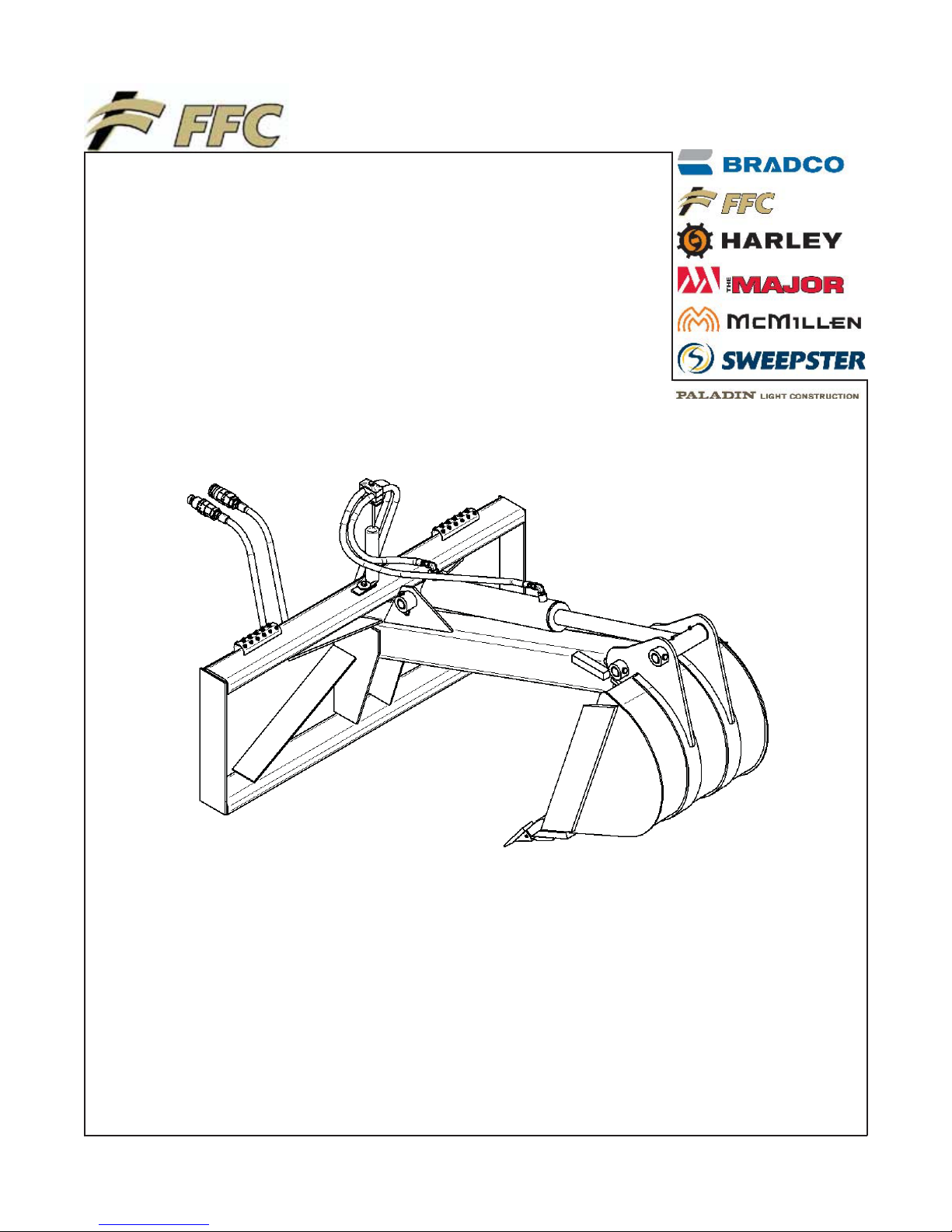
SKID STEER
BACKHOE
SERIAL NUMBER: ___________________ Manual Number: MR25515
Models: LAF2301, LAF2302
MODEL NUMBER: ___________________ & LAF2303
Date: August 2007
800-747-2132 I www.paladinbrands.com 100 East Lee Road, Lee, IL 60530, United States of America
Page 2

Page 3

TABLE OF CONTENTS
Introduction, General Information, Serial Number ……………………………………… 1
Owner and Operator Safety Information ………………………………………………… 2-5
Definitions of Safety Terms and Symbols, Accident Prevention …………… 2
Safety Instructions ...............................……..………………………………… 3-4
Safety Signs ...............................…...................................………………….. 5
Power Unit Specifications…………….…………………………………………………… 6
Installation Instructions...……………………………….…………………………………. 6
Hydraulic Connection...……………………………………………………………………. 6
Operation …………………………………………………………………………………….. 7-8
Maintenance …………………………………………………………………………………. 9
Service ……………………………………………………………………………………….. 9-10
Parts Illustration …………………………………………………………………………….. 11
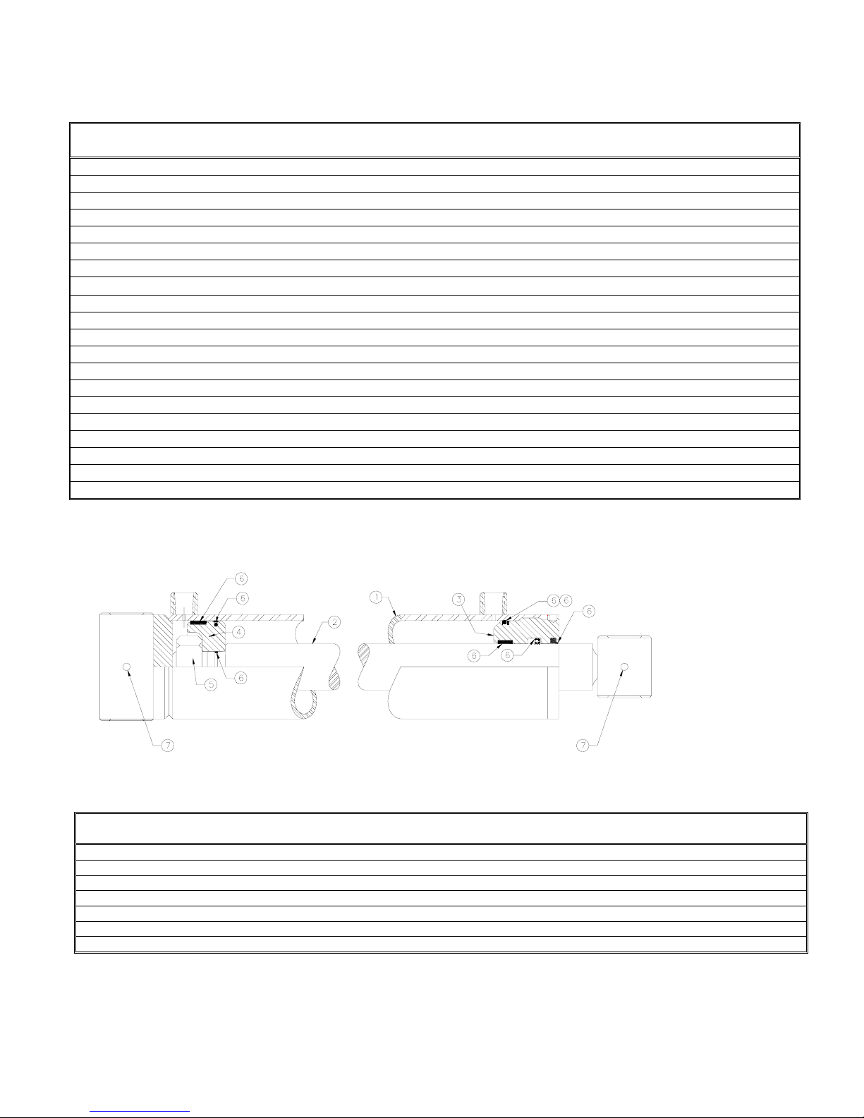
Parts List, Hydraulic Cylinder Illustration ………………………………………………… 12
Supplemental ……………………………………………………………………………….. 13-14
Specifications...………………………………………………………………………………. 15
Warranty ………………………………………………………………………………….. i
INTRODUCTION
Congratulations on your purchase of a new FFC Backhoe. This product has been designed and built to dig holes and
trenches up to 60” deep. You or any other person who will be assembling, operating, maintaining, or working with this
product are required to read and completely understand the information and instructions contained in this manual. If
anyone does not fully understand every part of this manual, please obtain further assistance by contacting the dealer
from which this product was purchased or by contacting FFC at the telephone number or address listed on the cover
of this manual. Keep this manual available for reference whenever this product is being handled or used. Provide
this manual to any new owners and/or operators.
This manual covers model[s] : LAF2301, LAF2302 and LAF2303. The difference between these models is the width
of the backhoe bucket, details of which are covered on the parts list and specification page[s].
GENERAL INFORMATION
The purpose of this manual is to assist in assembling, mounting, operating, and maintaining your Backhoe: Read this
manual carefully to obtain valuable information and instructions that will help you achieve safe and dependable service.
The illustrations and data used in this manual were current at the time of printing, but due to possible engineering
and/or production changes, this product may vary slightly in detail. FFC reserves the right to redesign and/or change
components as necessary without notification.
Throughout this manual, references may be made to:
Power Unit The engine-driven machine to which this product must be attached.
Right, Left, Front, Rear
IMPORTANT
NOTICE
Directions that are determined in relation to the operator of the equipment when seated
in the normal operating position.
Precautions that must be followed to prevent damage to equipment.
Precautions that must be followed to prevent substandard performance.
SERIAL NUMBER LOCATION
Always refer to the model and serial number when ordering parts or requesting information from your dealer. The
serial number plate for this product is located on the upper left rear portion of the loader attachment plate of your
Backhoe .
Reference Information
Model Number Loader Make
Serial Number Loader Model
Date Purchased Loader Serial Number
1
Page 4

DEFINITION OF SAFETY TERMS AND SYMBOLS
Throughout this manual, the terms DANGER, WARNING, and CAUTION are used to indicate the degree of hazard to
personnel if proper safety procedures are not followed. These words will be used in conjunction with the Safety Alert
Symbol: a dark triangle containing a white exclamation mark.
The Safety Alert Symbol means:
ATTENTION! BECOME ALERT! YOUR SAFETY IS INVOLVED!
DANGER
WARNING
CAUTION
Indicates an imminently hazardous situation which, if not avoided,
WILL result in death or serious injury.
Indicates a potentially hazardous situation which, if not avoided,
could result in death or serious injury.
Indicates a potentially hazardous situation which, if not avoided,
may result in minor or moderate injury;
may also be used to alert against unsafe practices which may result in personal injury.
ACCIDENTS CAN BE PREVENTED WITH
YOUR HELP!
No accident prevention program can be successful
without the wholehearted cooperation of the person who
is directly responsible for the operation of the equipment.
To read equipment accident reports from all over the
country is to be convinced that a large number of
accidents can be prevented only by operators who
consistently anticipate the results of their actions and
thus prevent accidents from ever occurring. No powerdriven equipment, whether it is on the highway, in a farm
field, or in an industrial plant, can be any safer than the
person who is at the controls.
OR
YOU
ARE THE KEY TO SAFETY BECAUSE:
YOU
are responsible for the SAFE operation and
maintenance of YOUR
YOU
are responsible to familiarize yourself, and anyone
else who will assemble, operate, maintain, or work
around this product, with the safety information
contained in this manual.
Backhoe.
YOU
If accidents are to be prevented [and accidents can be
prevented], that prevention will come from equipment
operators who accept their complete responsibility.
The designer, the manufacturer, and the safety engineer
all help create a safe product, but their combined efforts
can be wiped out with a single careless act by the
operator of that product.
The best safety device is a careful operator. FFC and
your dealer ask that YOU
equipment operator.
be that careful, responsible
2
are responsible to read ALL information contained
in this manual to any operators or maintenance
personnel who are not fully able to read the written
English language. Whether YOU
written or translate it into another language, YOU must
make certain that all operators and maintenance
personnel have a complete understanding of the full and
exact contents of this manual. Translations of this
manual into other languages are available by submitting
a written request to FFC.
YOU
can reduce the risk of injury or death by following
all safety precautions and by using good safety
practices.
read the manual as
Page 5
SAFETY INSTRUCTIONS
WORK SAFELY - A CAREFUL OPERATOR IS THE BEST INSURANCE AGAINST ACCIDENTS !!
SECTION 1
WARNING SECTION
WARNING
Obey all the safety instructions listed in
this section and throughout this
manual. Failure to obey instructions in
this section could result in death or
serious injury.
BEFORE ATTEMPTING ANY TYPE OF ASSEMBLY,
OPERATION, MAINTENANCE, OR OTHER WORK ON
OR NEAR THIS PRODUCT:
x READ AND COMPLETELY UNDERSTAND THIS
MANUAL.
x READ AND COMPLETELY UNDERSTAND THE
MANUALS PROVIDED WITH YOUR POWER
UNIT, LOADER AND QUICK-ATTACH.
x Read and understand all safety signs on this
product and on your power unit, loader, and quickattach.
x Know all your controls and know how to quickly
stop all power unit movement, the Backhoe
movement, and the engine in case of an
emergency.
x Know and obey all applicable government rules,
O.S.H.A. regulations, local laws and other
professional guidelines for your operation.
x Make sure that anyone who will be assembling,
mounting, maintaining, repairing, removing, and/or
storing this product:
¾ has been instructed in the safe operation of this
product and
to which this product is attached.
¾ is physically and mentally capable of the safe
operation of this type of equipment.
¾ is not under the influence of drugs or alcohol.
¾ is carefully supervised from a safe distance,
especially if such person is inexperienced.
¾ wears appropriate protective equipment (i.e.
hardhat, safety glasses, work gloves, protective
shoes, respirator, ear protection, etc.).
¾ does not wear loose fitting clothing, loose or
uncovered hair, or any accessories (jewelry,
necktie, scarf, wrist watch, etc.) that can catch
in moving parts.
¾ has annually reviewed all safety instructions.
x Know and follow good work practices when
assembling, mounting, maintaining, repairing,
removing, and storing this product:
¾ Work on a level surface in a well lit area.
¾ Keep the area clean and dry.
¾ Use properly grounded electrical outlets &
tools.
of the power unit and quick-attach
¾ Use the right tool for the job at hand.
¾ Make sure that your tools are in good condition for
performing the desired function.
¾ When using tools, wear the protective equipment
specified by the tool manufacturer. (i.e. hardhat,
safety glasses, work gloves, protective shoes,
etc.)
WHEN YOUR POWER UNIT IS USED DURING ANY
TYPE OF ASSEMBLY, OPERATION,
MAINTENANCE, OR OTHER WORK ON OR NEAR
THIS PRODUCT:
x Before leaving the operator’s station or before
beginning any type of work on this product, lower this
product to the ground, apply your power unit’s parking
brake, stop the engine, remove the starter key, wait for
all moving parts to stop, and then relieve all pressure
in the hydraulic lines. Refer to your power unit’s
operator’s manual for instructions on how to relieve
hydraulic pressure in lines.
x Know your loader’s safe lifting and operating capacity
and the weight of this product. See the specifications
in this manual for the weight of this product and refer
to your power unit’s and loader’s operator’s manuals
for safe operating limits. Lift capacity may be reduced
if using a quick-attach.
x Never allow anyone, except the operator, to be around
the power unit or this product when either is in motion.
x
Do not startup unless others are clear of the work area.
x Do not allow riders on this product or the power unit.
x Do not stand or climb on this product when raised.
x Do not place any part of your body under any part of
this product unless this product is securely resting on
adequate blocking or on the ground.
x Do not use blocking made of concrete blocks, logs,
buckets, barrels or any other material that could
suddenly collapse or shift positions. Do not use wood
or steel blocking that shows any signs of material
decay. Do not use blocking that is warped, twisted, or
tapered.
x Never operate controls from the ground. Operate the
controls only from the operator’s station.
x Never leave equipment unattended with the engine
running or with this product raised on the loader.
x Be aware of the added weight and width of this
product. Reduce travel speeds accordingly, especially
when traveling over rough ground.
x Keep this product close to the ground and under control
when transporting.
x When transporting, be sure backhoe does not block
view of vehicle lights or road.
3
Page 6
SAFETY INSTRUCTIONS
WORK SAFELY - A CAREFUL OPERATOR IS THE BEST INSURANCE AGAINST ACCIDENTS !!
x If this product does not fit properly, contact FFC
WARNING SECTION
[CONTINUED]
WARNING
Obey all the safety instructions
listed in this section and throughout
this manual. Failure to obey
instructions in this section could
result in death or serious injury.
WHEN DEALING WITH HYDRAULICS DURING ANY
TYPE OF ASSEMBLY, OPERATION, MAINTENANCE,
OR OTHER WORK ON OR NEAR THIS PRODUCT:
x Hydraulic fluid under pressure can penetrate the
skin and cause serious injury or death. Hydraulic
leaks under pressure may not be visible!
x If any fluid penetrates the skin, GET IMMEDIATE
MEDICAL ATTENTION!!
x Wear safety glasses, protective clothing, and use a
sound piece of cardboard or wood when searching
for hydraulic leaks. DO NOT USE YOUR HANDS!
x Before connecting or disconnecting hydraulic hoses,
read your tractor or power unit’s operator’s manual
for detailed instructions on connecting and
disconnecting hydraulic attachments.
x
Make certain that all parts meet the specifications for
this product when installing or replacing hydraulic
hoses or fittings.
x After connecting hydraulic lines:
¾ Slowly and carefully raise the loader and cycle
the rollback / dump cylinders to check hose
clearances and to check for any interference.
¾ Operate the hydraulics on this product to check
hose clearances and to check for any
interference.
¾ Make certain that the hoses cannot interfere with
or actuate the quick-attach mechanism.
¾
Make certain that hoses will not be pinched, or
get tangled, in any equipment.
x Do not lock the auxiliary hydraulics of your power
unit in the “ON” position.
x Refer to your power unit’s operator’s manual and
this manual for procedures and intervals, then
inspect and maintain the entire hydraulic system to
insure that the fluid remains clean, that all devices
function properly, and that there are no fluid leaks.
WHEN MOUNTING THIS PRODUCT TO YOUR
POWER UNIT:
x Refer to the operator’s manuals of your power unit,
your loader, and your quick-attach for special or
detailed mounting instructions.
x This product should fit onto the quick-attach or
loader arms of your power unit the same as the
original products that were designed by your loader /
quick-attach manufacturer.
before operating.
x Never place your finger into the mounting plate or 3-
point hitch or loader holes. A slight movement of the
power unit or this product could cause serious injury.
BEFORE EACH USE, THOROUGHLY INSPECT THIS
PRODUCT AND:
x Make certain that all safety signs are in place and
legible. Refer to the safety sign page in this manual
for the placement of safety signs for this product.
x Replace all damaged or excessively worn parts and
hardware only with genuine FFC parts or with
properly rated fasteners, hydraulic hoses, or fittings.
x Make certain that all locking pins, latches, and
connection devices are properly installed and
secured.
x Make certain that all protective guards, canopies,
doors, etc., are in place and secure.
WHEN OPERATING THIS PRODUCT IN
ACCORDANCE WITH DESIGN INTENTIONS:
x
Contact utility companies before digging. Know your
digging area! Avoid hitting underground cables and
pipes, overhead wires, and other hazards.
x
Do not drive near the trench. Always back away from
the trench before turning.
x
Never use backhoe on a power unit that is not
equipped with a cab or ROPS, and operator
restraints (seat belts or equivalent devices).
x
Do not use the backhoe to dislodge overhead
objects. Objects could fall and cause injury.
x
Do not attach a jack hammer to the backhoe.
x
Be careful when raising loaded bucket. Objects
could fall from bucket toward bystanders or operator.
x
Know your loader’s safe operating weight limit, and
the weight of loaded attachment.
x
Never dig close to loader’s wheels or under the
loader; this can cause a cave in and vehicle
overturn.
x
Do not drive near the trench. Always back away from
trench before turning.
x
Always dump loaded bucket on uphill side of
backhoe to minimize possibility of upset.
x
Use caution when working close to fences and
ditches, or on uneven ground.
WHEN ADJUSTING, SERVICING OR REPAIRING THIS
PRODUCT:
x Make no modifications to your Backhoe.
x When making repairs, use only genuine FFC parts
or, for fasteners, hydraulic hoses, or hydraulic
fittings, use only properly rated parts.
x Replacement parts, for parts with safety signs
attached, must also have safety signs attached.
4
Page 7
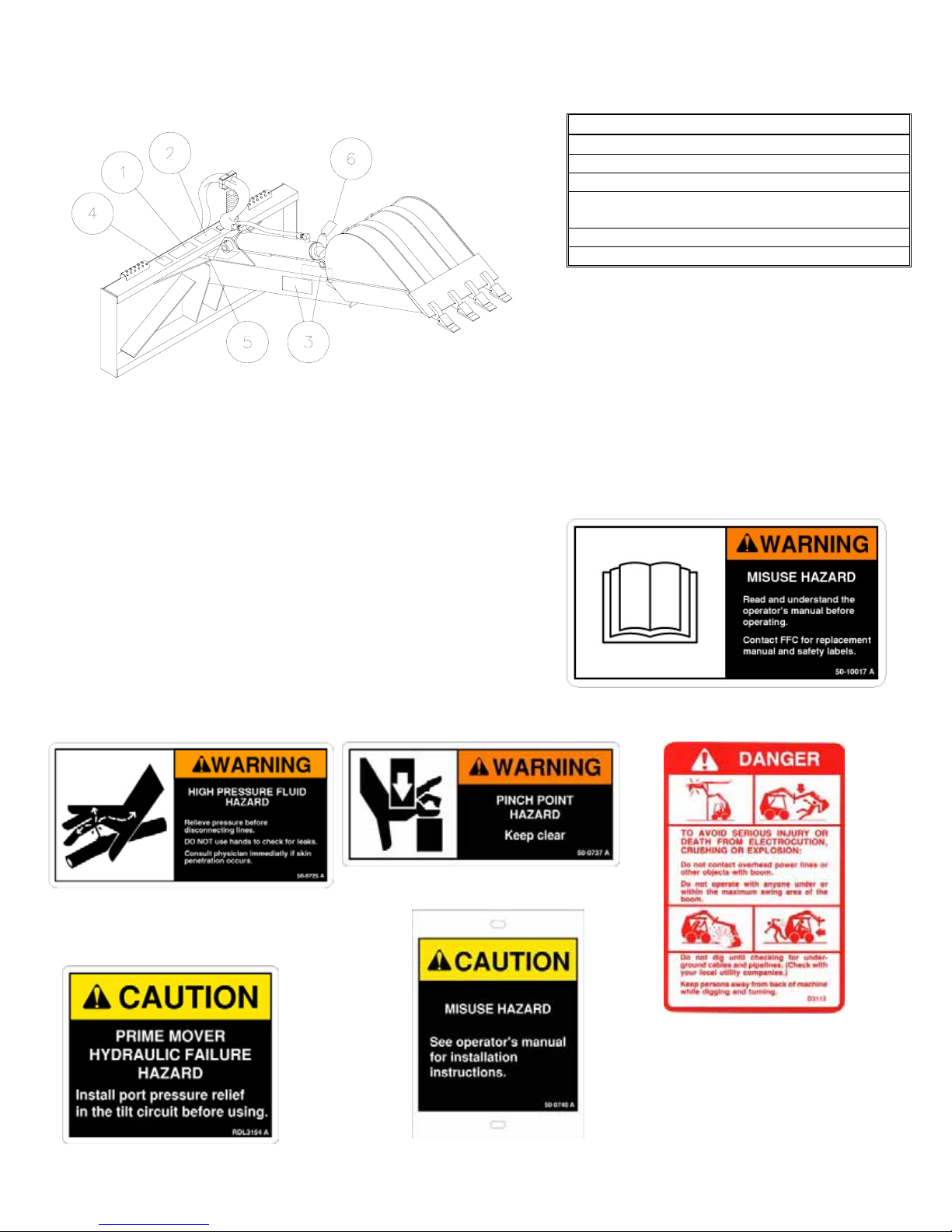
SAFETY SIGN LOCATIONS
ITEM QTY PART # DESCRIPTION
1 1 50-10017 READ MANUAL
2 1 50-0725 HYDRAULIC
3 2 50-0737 PINCH POINT
4 1 RDL3113 DANGER
BACKHOE
5 1 RDL3154 PORT RELIEF
6 1 50-0740 TAG-MISUSE
INSTRUCTIONS
x Keep all safety signs clean and legible.
x Replace all missing, illegible, or damaged
safety signs.
x Replacement parts for parts with safety signs
attached must also have safety signs
attached.
x Safety signs are available free of charge from
your dealer or from FFC.
PLACEMENT OR REPLACEMENT OF
SAFETY SIGNS
1. Clean the area of application with non-flammable
solvent, then wash the same area with soap and
water.
2. Allow the surface to fully dry.
3. Remove the backing from the safety sign, exposing
the adhesive surface.
4. Apply the safety sign to the position shown in the
diagram above and smooth out any bubbles.
ITEM 2 ITEM 3 ITEM 4
ITEM 5
ITEM 1
ITEM 6
5
Page 8
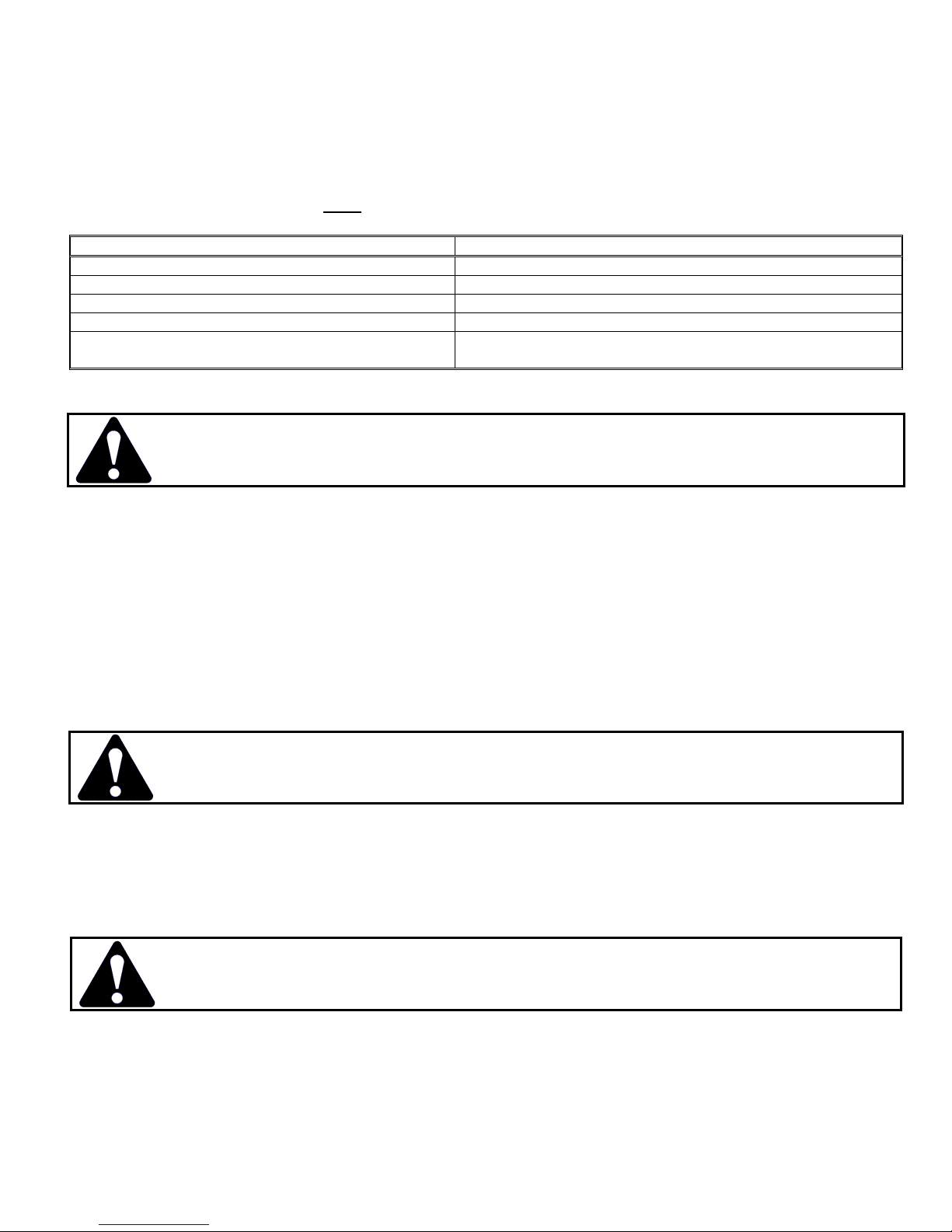
POWER UNIT SPECIFICATIONS
IMPORTANT
LOADER DESCRIPTION MAXIMUM BUCKET SIZE
LESS THAN 25 HORSEPOWER DO NOT USE MINI-HOE
25 – 35 HORSEPOWER 12” BUCKET
35 – 45 HORSEPOWER 18” BUCKET
45 OR GREATER HORSEPOWER 24” BUCKET
POWER UNIT’S TILT CURCUIT HAS NO PORT
RELIEF
Exceeding any of the recommended power unit specifications
CAN result in damage to your power unit and/or this product and
WILL
void all FFC warranties
INSTALL RELIEF VALVE FOR POWER UNIT’S TILT
CIRCUIT
BACKHOE INSTALLATION INSTRUCTIONS
SAFETY FIRST!! READ AND UNDERSTAND THE SAFETY INSTRUCTIONS (pages 2-5 of
this manual) BEFORE BEGINNING ANY BACKHOE MOUNTING
1. Place this product on a firm, level surface that is large enough to safely accommodate this product, your power
unit, and all workers involved in the mounting process.
2. Be sure all connection points are properly secured.
3. Refer to the operator’s manual(s) for your power unit, loader, and quick-attach and follow the mounting instructions
contained therein.
4. Carefully raise the loader arms and cycle the tilt cylinders to check clearances and to verify that all mounting
procedures have been successfully completed.
5. All power units MUST have a port relief installed on its hydraulic tilt circuit. See Supplemental Information starting
at page 13.
BACKHOE HYDRAULIC CONNECTION
SAFETY FIRST!! READ AND UNDERSTAND THE SAFETY INSTRUCTIONS (pages 2-5 of
this manual) BEFORE BEGINNING ANY BACKHOE HYDRAULIC CONNECTION
1. Disconnect the hydraulic hose quick couplers from one another and attach the quick couplers to your power unit as
per the instructions in your power unit’s operator’s manual.
2. Carefully raise the loader arm and cycle the tilt cylinders to check hose clearances and to check for any
interference.
WARNING
Do not lock the auxiliary hydraulics of your tractor or power unit in the “ON” position. Failure to
obey this warning could result in death or serious injury.
6
Page 9

BACKHOE OPERATION
SAFETY FIRST!! READ AND UNDERSTAND THE SAFETY INSTRUCTIONS (pages 2-5 of
this manual) BEFORE BEGINNING ANY BACKHOE OPERATION
DANGER
Failure to obey the following procedures will result in death or serious injury.
x
Avoid contacting overhead wires and underground pipes or cables. Failure to heed may
result in electrocution or explosion.
WARNING
Failure to obey the following procedures could result in death or serious injury.
Never lift this product:
x
above the operator’s eye level OR
x
to a height where visibility is obstructed, whichever is lower
Use caution when raising loaded bucket. Objects could fall from bucket toward bystanders or
operator.
.
NOTICE
TO DIG:
1. Be sure the loader is on solid ground before digging or lifting any load.
2. With the loader arms partially raised and the bucket cylinder partially extended, slowly curl the dipperstick toward
the loader (using the loader’s tilt control). The loader arms may need to be lowered or raised and/or the bucket
cylinder extended to allow the bucket to penetrate the soil.
3. As the bucket fills, extend the bucket cylinder and extend the dipper or raise the loader arms to lift the bucket
clear of the hole.
4. The depth of the hole will be controlled by the amount the dipper is extended and the height of the loader arms.
x
Use extreme care when working on hillsides. Always dump loaded bucket on uphill side of backhoe to
minimize possibility of upset.
x
Exercise caution when working close to fences, ditches, or on uneven ground.
DO NOT:
x
Dig close to the loader’s wheels or under the loader; this could cause a cave-in and vehicle overturn.
TO DUMP ON GROUND:
1. With the bucket raised clear of the hole, slowly back up and pivot the loader rearward about the front wheels. This
will swing the loader away from the trench, and the bucket to the side to dump.
x
Keep loads close to the ground while transporting.
USE OF REAR COUNTERWEIGHTS IS REQUIRED!
Refer to your power unit’s operator’s manual for safe operating limit and use of counterweights.
7
Page 10
BACKHOE OPERATION (continued)
SAFETY FIRST!! READ AND UNDERSTAND THE SAFETY INSTRUCTIONS (pages 2-5 of
this manual) BEFORE BEGINNING ANY BACKHOE OPERATION
DANGER
Failure to obey the following procedures will result in death or serious injury.
x
Avoid contacting overhead wires and underground pipes or cables. Failure to heed may
result in electrocution or explosion.
WARNING
Failure to obey the following procedures could result in death or serious injury.
Never lift this product:
x
above the operator’s eye level OR
x
to a height where visibility is obstructed, whichever is lower
Use caution when raising loaded bucket. Objects could fall from bucket toward bystanders or
operator.
TO CUT A SHALLOW TRENCH
1. With the loader arms partially raised and the bucket cylinder partially extended, slowly curl the dipperstick toward
the loader (using the loader’s tilt control). The loader arms may need to be lowered or raised to allow the bucket
to penetrate the soil.
2. When the bucket is positioned at the desired depth, slowly back up the loader, keeping the bucket height constant
to cut a shallow amount of soil.
IMPORTANT
The tilt circuit of your power unit must be protected with a port relief; ignoring this precaution
CAN result in damage to your power unit and/or this product and
WILL
void all FFC warranties
.
WARNING
Always back away from trenches before turning.
Failure to obey this warning could result in death or serious injury.
TO FILL A TRENCH
1. With the loader arms partially raised, curl the dipperstick (attachment mainframe) forward with the bucket
cylinder extended and the bottom of the bucket flat on the ground. The entire height of the bucket should be
visible.
2. Use the loader’s tilt cylinder only to raise the bucket above the material pile.
3. Pivot the loader to reach over the pile and tilt the backhoe downward so the bottom of the bucket is
approximately 12” below the top of the pile.
4. Pivot the loader toward the trench, using the side of the bucket to move the material into the trench. Repeat this
process, lowering the bucket 6” at a time.
5. Move your power unit forward and repeat the above steps to continue filling the trench.
IMPORTANT
x Always lower the bucket to the ground, set the parking brake, stop engine, remove ignition key and wait for all
moving parts to stop before leaving the operator’s seat.
Make sure the portion of the trench to be driven on is full before moving forward.
Moving on an unstable surface
CAN result in damage to your power unit and/or this product and
WILL
void all FFC warranties
8
Page 11

BACKHOE MAINTENANCE
SAFETY FIRST!! READ AND UNDERSTAND THE SAFETY INSTRUCTIONS (pages 2-5
of this manual) BEFORE BEGINNING ANY BACKHOE MAINTENANCE
BEFORE FIRST USE
x
Inspect the attachment for shipping damage. If damage does exist, do not operate until the damaged parts have
been replaced or repaired.
BEFORE EACH USE
x Make sure that all nuts and bolts are in place and properly tightened.
x Make sure that all other fasteners are in place and are performing their specified function.
x Make sure that all hydraulic fittings are tightened and that there are no leaks in any fittings or hoses.
x Make sure that all safety signs are in place, are clean, and are legible.
(SEE THE SAFETY SIGN SECTION)
x Replace any damaged parts and excessively worn parts.
x Grease all (5) lubrication points.
AFTER EVERY 4 HOURS OF OPERATION
x Grease all (5) lubrication points.
BACKHOE SERVICE
SAFETY FIRST!! READ AND UNDERSTAND THE SAFETY INSTRUCTIONS (pages 2-5
of this manual) BEFORE BEGINNING ANY BACKHOE SERVICE
Tilt Circuit secondary Relief Valve Installation:
x
The purpose of this valve is to relieve high pressure in the loader’s tilt circuit when the loader’s main control valve
does not have port relief for this circuit. Read these instructions and your power unit’s manual(s) before
attempting installation.
WARNING
Hydraulic fluid under pressure can penetrate the skin, resulting in serious injury or death.
Always relieve hydraulic pressure before disconnecting lines.
x Shut off engine, set parking brake, and relieve hydraulic pressure before connecting or disconnecting hydraulic
lines. Refer to your power unit’s manual for instructions on how to relieve hydraulic pressure in lines.
x Before applying pressure to the system, be sure that all connections are tight and be sure there are no damaged
hoses, lines, or fittings.
x Wear safety glasses and use metal or wood when searching for leaks. Do not use your hands.
WARNING
Before servicing the loader, remove the attachment and make certain the lift arms are lowered
to their lowest position or that the arms are supported by the mechanical lock up devices
(if the machine is so equipped).
x Steam clean the power unit before any installation is made to the hydraulic system. Remove any attachment from
the power unit and position on a level surface.
9
Page 12
BACKHOE SERVICE (continued)
SAFETY FIRST!! READ AND UNDERSTAND THE SAFETY INSTRUCTIONS (pages 2-5
of this manual) BEFORE BEGINNING ANY BACKHOE SERVICE
x
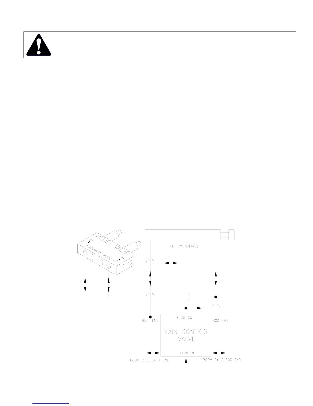
Locate a convenient place to “tee” into the loader’s tilt circuit lines after they have passed through any selfleveling devices or any other devices which may be present on these lines (refer to your loader’s service manual).
Locate a convenient area to “tee” into a return to tank line. Once these areas are located, find an area in close
proximity for mounting the relief valve. The valve can be mounted in any position. Every effort should be made to
ensure accessibility to the valve, its cartridges, fittings and any lines that will be added. Careful consideration
should also be made as to the type and size of the fittings and hoses that will be required before dismantling any
hydraulic circuitry. Keep any added fittings, hoses, or the valve a safe distance from all moving parts of the
machine. 3/8” pipe fittings, ½” SAE o-ring or JIC fittings and 3/8” hydraulic hoses are all adequate for the amount
of flow required. The valve’s ports accept 3/8” NPT pipe fittings or SAE #8 o-ring, depending on the model of
valve. Be sure to differentiate between the two styles before proceeding.
NOTICE
x Install the line from the butt end of the loader’s tilt cylinders into port “B” on the valve. Install the line from the rod
end of the cylinder into port “R” on the valve and the return to tank line into port “T”. Make sure all fittings and
hoses are tightened securely and no hoses are stretched, severely bent, or kinked before mounting the valve.
x Using the valve as a template, mark the location of two 9/32” holes. Remove the three lines connected to the
valve and seal the line ends to keep out contaminants. Drill the previously located holes.
IMPORTANT
x Reassemble the three lines onto the valve and install mounting bolts. Check all connections for proper fit and
tightness.
x Replace all guards, shields, and covers.
x Replace estimated lost hydraulic fluid using your loader’s specifications.
x Start loader; reposition the boom arms and dump cylinders according to the loader manufacturer’s
recommendations for checking fluid levels. Add fluid as needed.
If using NPT pipe fittings (anywhere on the loader’s circuit), it is recommended that you use a eflon
based thread sealant. Do NOT use eflon tape as it may enter the loader hydraulic circuit and cause
relief poppets to stick open.
When drilling holes, be sure that you are not drilling into a reservoir or any other sealed
compartment. Also be careful not to damage any hydraulic lines, fittings, pumps, valves,
manifolds, electric components, batteries, steering linkages, safety devices, etc.
10
Page 13
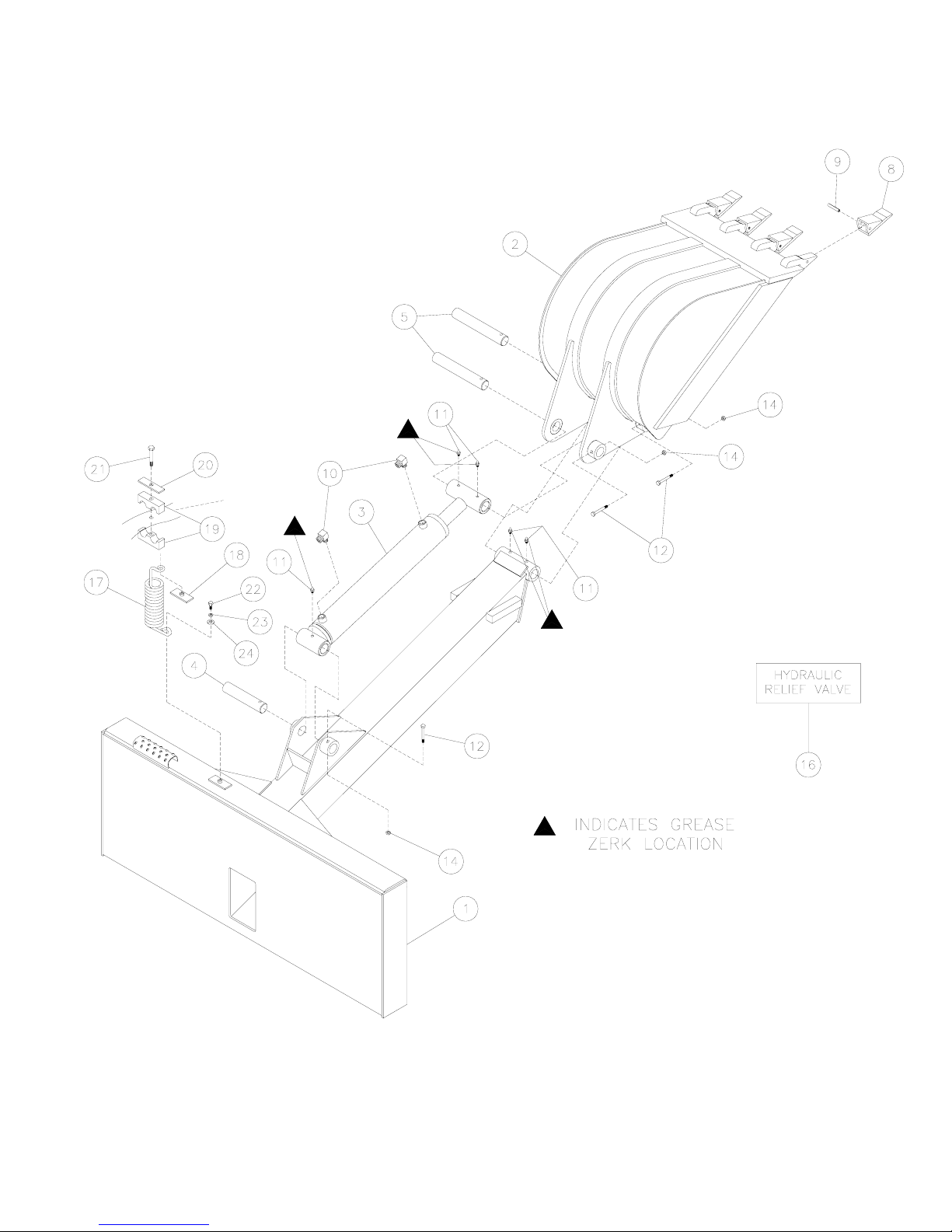
PARTS ILLUSTRATION
11
Page 14
BACKHOE: PARTS LIST
LAF2301 LAF2302 LAF2303
ITEM QTY. 12” 18” 24” DESCRIPTION
1 1 LAF2304 Attachment Mainframe
2 1 LAF2312 LAF2318 LAF2324 Backhoe Bucket
3 1 LAF4562 Hydraulic Cylinder:3” x 1-3/4”, 4000 psi
4 1 LAF9973 Pin: 1-1/4” x 7-1/4”, stressproof
5 2 LAF9972 Pin: 1-1/4” x 8-5/8”, stressproof
8 varies (3) (4) (5) LAF1000 Replaceable Point: 1”
9 varies (3) (4) (5) RHW8026 Roll Pin: 5/16” x 1-3/4”
10 2 LAF4298
11 5 RHW8090 Grease Zerk: ¼”, 28 tpi, self-tapping
12 3 RHW1213 Grade 5 Hex Head Cap Screw: 3/8” x 2-1/2”
14 3 RHW7203 Grade 5 Lock Nut: 3/8”
16 1 Contact FFC to obtain the correct item Hydraulic Relief Valve
17 1 RHW8618 Hose Spring
18 1 RHW8613 Weld Plate: 7/8” OD
19 1 RHW8616 Hose Cradle: 7/8” OD
20 1 RHW8614 Cover Plate: 7/8” OD
21 1 RHW1112 Grade 5 Hex Head Cap Screw: 5/16” x 2-1/2”
22 1 RHW1101 Grade 5 Hex Head Cap Screw: 5/16” x ½”
23 1 RHW6102 Grade 5 Lock Washer: 5/16”
24 1 RHW8098 Grade 2 Fender Washer: 5/16” x 1-1/2” (.08” thick)
NOTE: All parts are the same as the LAF2303 except for those parts numbered under the other model.
Hydraulic Elbow: 90q, 6MB – 6MJ
HYDRAULIC CYLINDER
ILLUSTRATION: LAF4562
NUMBERS FROM HYDRAULIC CYLINDER ILLUSTRATION: LAF4562
ITEM QTY. PART # DESCRIPTION
1 1 LAF4612 Barrel: 3” Tube Assembly
2 1 LAF4611 Shaft: 1-3/4” Shaft Assembly
3 1 LAF4610 Head: 3”
4 1 LAF4609 Piston: 3”
5 1 LAF4608 Nut: Grade 8, 1-1/8”, 12 tpi
6 1 LAF4607 Seal Kit (includes all seals, o-rings, etc.)
7 3 RHW8090 Grease Zerk: ¼”, 28 tpi., self-tapping
12
Page 15
SUPPLEMENTAL
#8
5939
IMPORTANT
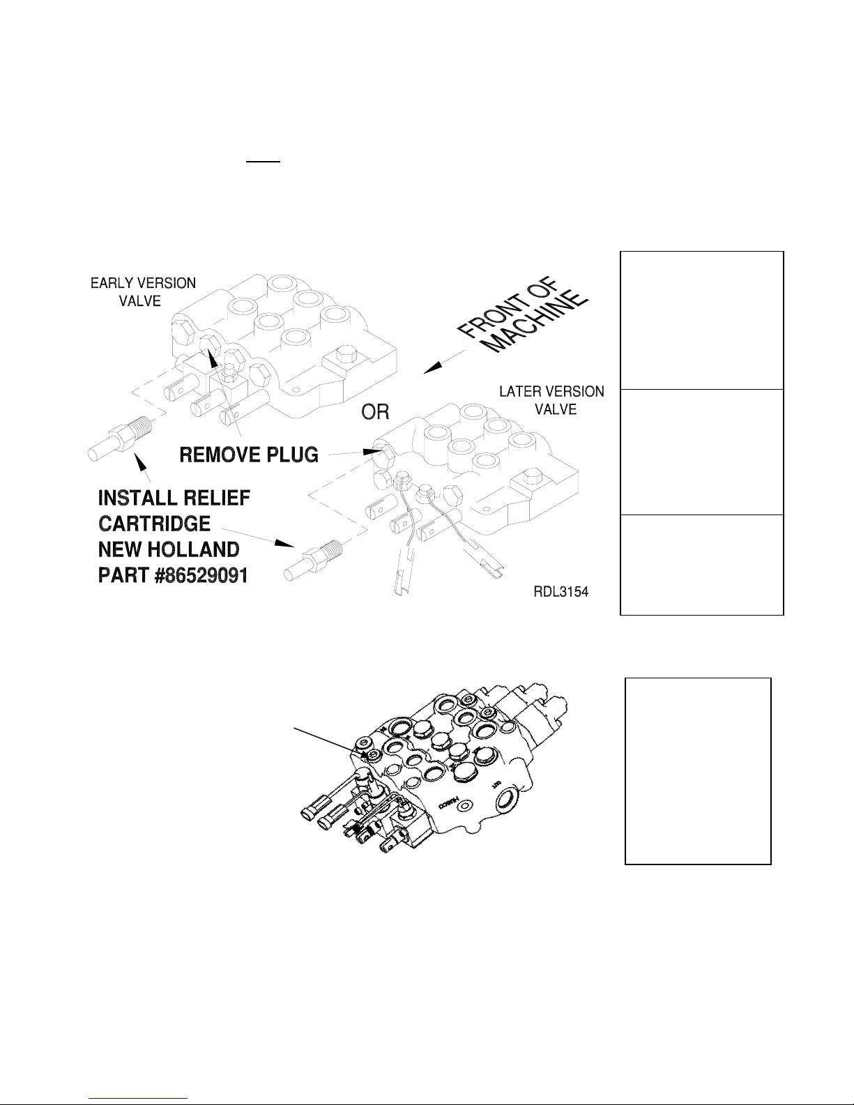
NEW HOLLAND LOADERS:
Install relief cartridge in bucket cylinder base end port of control valve before operating the Mini Hoe.
Failure to install a Relief Cartridge as specified below
CAN result in damage to the power unit and
WILL
void all FFC warranties
EARLY VERSION:
L / LX 465
LX 485
L / LX 565
LX 665
L / LX 865
LX 885
LX 985
EARLY OR LATER:
LS 140
LS 150
LS 160
LS 170
LS 180
LS 190
FOR NH LS.B, LT.B,
L180-L190, C185, C190
MODELS REMOVE
EXISTING CARTRIDGE
AND INSTALL RELIEF
CARTRIDGE
744
LATER VERSION:
L 140
L 150
L 160
L 170
LS 180.B
LS 185.B
LS 190.B
LT 185.B
LT 190.B
L180
L185
L190
C185
C190
13
Page 16
SUPPLEMENTAL (continued)
FOR CASE LOADERS:
CASE 1845C and CASE XT power units require no additional relief.
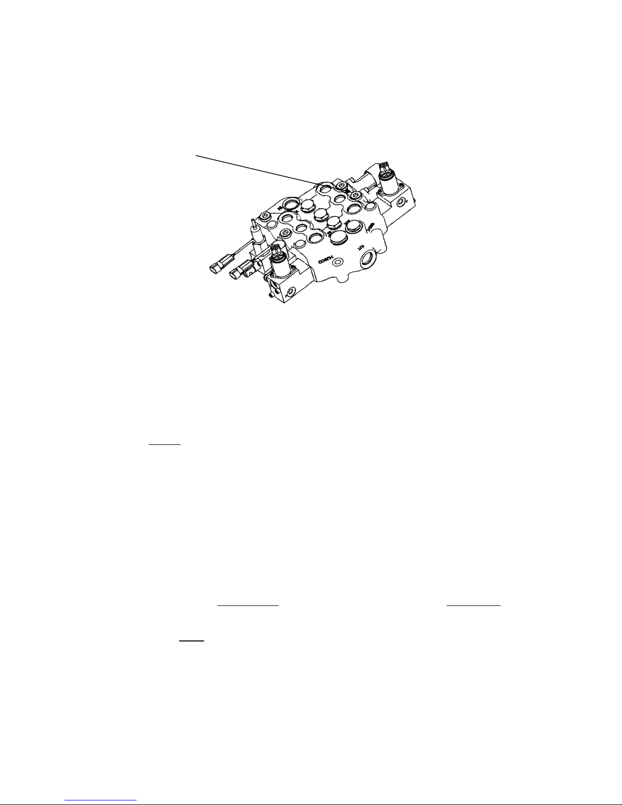
FOR CASE 400-SERIES
MODELS REMOVE
EXISTING CARTRIDGE
AND INSTALL RELIEF
CARTRIDGE #87445935
OTHER LOADERS:
For other makes of machines using a screw-in cartridge relief, the base end (opposite the rod end) of the tilt
cylinder(s) needs to be protected. Contact your dealer to confirm which (plugged) port the cartridge should be
inserted.
Bobcat power units with BICS (Bobcat Interlock Control System) require no additional relief.
Bobcat power units without
cartridge (to replace the plug).
John Deere 4475, 5575, 6675, 7775, and 8875 power units require the JD part # MG86529091 cartridge.
John Deere 240, 250, 260, 270 and 280 power units with serial number lower than 400000 must use FFC part #
LAF4264.
However, 200 series 4th year production models require no additional relief. These may be identified with serial
numbers greater than: 440001 (JD240), 450001 (JD250), 460001 (JD260), 470001 (JD270), and 480001 (JD280).
John Deere 317, 320, 325, 328 and 332 power units also require no additional relief.
Scat Trak 1700 HD power units require no additional relief.
GEHL 7600, 7610, 7800 & 7810 and Mustang 2095, 2099, 2105 & 2109 skidloaders can utilize a relief cartridge
(GEHL part #138703) screwed into their main control valve opposite the existing cartridge on the tilt circuit spool,
eliminating the need for FFC’ dual cross over relief.
IMPORTANT
Contact your skidloader dealer to obtain the correct relief cartridge and instructions for installation.
This cartridge is IN ADDITION to the existing relief cartridge, and is REQUIRED to protect
the circuit of your power unit. Failure to install the extra cartridge
CAN result in damage to your power unit and this product and
BICS but with a plug and a relief on the tilt spool require Bobcat part # 6599161
WILL
void all FFC warranties
Other power units require FFC part # LAF4264.
Contact your dealer to confirm the proper relief is used.
14
Page 17

BACKHOE SPECIFICATIONS
Model
Number
LAF2301 48” 34” 86” 1.25 cu. feet 3 60” 635 lbs
LAF2302 48” 34” 86” 1.97 cu. feet 4 60” 665 lbs
LAF2303 48” 34” 86” 2.69 cu. feet 5 60” 695 lbs
* Struck capacity
** Approximate depth only. Power Unit will also affect depth capabilities.
Overall
Width
All replacement hydraulic hoses must have a minimum rated working pressure of 4,000 psi.
Overall
Height
Overall
Depth
Bucket
Capacity*
Qty. of
Teeth
Digging Depth
(max. to teeth)**
Shipping
Weight
TORQUE SPECIFICATIONS FOR STANDARD MACHINE HARDWARE
(FOR REFERENCE ONLY)
Bolt Size SAE Grade Bolt Torque Ft./Lbs
5/16” - 18 5 17
3/8” - 16 5 30
15
Page 18

Warranty Registration Form and Delivery Inspection Report
IMPORTANT! Warranty Void if card is not returned with 10 days.
All Applicable sections must be filled in.
This section to be filled out and signed by Dealer at time of delivery.
Warranty Registration
Customer’s Name Dealer’s Name
Address Address
City State Zip City State Zip
Phone CHECK ONE:
Loader / Tractor Model Construction Use
Delivery Date Agricultural Use
Model or Part # Landscape Use
Serial # Other:
Dealer Inspection (check items applicable)
All Decals installed (see operator’s manual) Review Operating and Safety Instructions
Hydraulic fittings tight and free of leaks Guards and covers in place and secure
Fasteners tight Does Product Function Properly
I have thoroughly instructed the buyer on the above described equipment. This review included: The Operator’s manual content,
equipment care, adjustments, safe operation and applicable warranty policy.
Date Dealer’s Rep. signature
This section to be completed and signed by the customer
QUALITY ASSURANCE RATING
Question: FFC Local Dealer
Quality of Product: Appearance . . . . . . . . . . . . . . . . . . . . . . . . .
Construction . . . . . . . . . . . . . . . . . . . . . . . . .
Quality of Service . . . . . . . . . . . . . . . . . . . . . . . . . . . . . . . . . . . .
Value (Priced Fairly) . . . . . . . . . . . . . . . . . . . . . . . . . . . . . . . . . .
Does it perform as claimed . . . . . . . . . . . . . . . . . . . . . . . . . . . . .
The above described equipment and Operator’s Manual have been received by me and I have been thoroughly instructed
as to care, adjustments, safe operation and applicable warranty policy.
Date: Owner’s signature
NOTE! Make one copy each for the dealer’s and owner’s records. Mail original to FFC Attachments.
Form MR00000-000 Rev. 09/04
FFC Attachments • 100 E. Lee Road • PO Box 122 • Lee, IL 60530 • 800-747-2132 • Fax 815-824-2071
www.ffcattachments.com
123 4 5
Excellent Good Average Unsatisfactory Poor
PLEASE TRI-FOLD AND AFFIX TAPE HERE
Page 19

FFC LIMITED 12 MONTH WARRANTY
Thank you for purchasing a FFC product. Warranty protection is valid only when this Warranty
Registration is completed and signed by the customer and dealer, and mailed to FFC. I hereby
acknowledge that I have received a copy of the owners Limited Warranty and I accept the terms
therein.
For a period of 12 months from date of delivery of product to the original user, FFC, warrants
each product to be free from manufacturing defects, subject to the limitations contained in this
policy.
This warranty does not apply to defect caused, in whole or in part, by unreasonable use while in
the possession of the user, including, but not limited to: failure to properly set up product; failure
to provide reasonable and necessary maintenance; normal wear; routine tune ups or
adjustments; improper handling or accidents; operation at speed or load conditions contrary to
published specification; improper or insufficient lubrication; improper storage. This warranty is
also not a guarantee that the performance of each product will meet the expectations of the
purchaser.
FFC shall not be liable for consequential damages of any kind, including, but not limited to:
consequential labor costs or transportation charges in connection with the replacement or repair
of defective parts; lost time or expense which may have accrued because of said defects. In no
event shall FFC, Inc.’s total liability hereunder exceed the product purchase price.
FFC makes no warranty with respect to trade accessories or any component or accessory of the
product which was not manufactured by FFC, including any purchased components on any kind.
These are subject to the warranties of their respective manufacturers. The warranty will be
considered void if the product or any part of the product is modified or repaired in any way not
expressly authorized by FFC, or if closed components are disassembled prior to return. Closed
components include, but are not limited to: gearboxes, hydraulic pumps, motors, cylinders, and
actuators.
Our obligation under the warranty is expressly limited, at our option, to the replacement or repair
at FFC, of Lee, Illinois, or at a service facility designated by us, or such part or parts as inspection
shall disclosed to have been defective. We are not responsible for unauthorized repairs or
replacements. Any implied or statutory warranties, including any warranty of merchantability or
fitness for a particular purpose, are expressly limited to the duration of this written warranty. We
make no other express or implied warranty, nor is anyone authorized to make any in our behalf.
This warranty cannot be extended, broadened, or changed except in writing by an authorized
officer of FFC.
 Loading...