

FFC 11048, 11060, 11072, 11096, 11078 Operator And Parts Manual
...
OPERATOR’S AND PARTS MANUAL
HYDRAULIC SNOW BLOWER
Serial Number: ___________________
Model Number: ___________________
800-456-7100 I www.paladinattachments.com 2800 N. Zeeb Rd., Dexter, MI. 48130, United States of America Copyright ©
Manual Number: 51-4694
Models:
STD: 11048, 11060, 11072, 11078 &
11084 (A through E)
HF: 11072, 11078, 11084 & 11096
(F through H)
Release Date: June 2015
Rev. 1
1

Notes
2

TABLE OF CONTENTS
PREFACE .....................................................................................................................................................4
SAFETY STATEMENTS ...............................................................................................................................5
GENERAL SAFETY PRECAUTIONS........................................................................................................5-7
EQUIPMENT SAFETY PRECAUTIONS ...................................................................................................7-8
SAFETY DECALS & LABELS .................................................................................................................9-10
INSTALLATION ....................................................................................................................................11-13
OPERATION ..........................................................................................................................................14-20
MAINTENANCE ...................................................................................................................................21-22
TROUBLESHOOTING ...............................................................................................................................23
PRODUCT SPECIFICATIONS ...................................................................................................................24
BOLT TORQUE SPECIFICATIONS ...........................................................................................................25
WARRANTY ...............................................................................................................................................26
STANDARD FLOW HOUSING ..............................................................................................................28-29
STANDARD FLOW CHUTE ................................................................................................................30-31
STANDARD HYDRAULICS .................................................................................................................32-35
STANDARD MOUNTING .........................................................................................................................36
HIGH FLOW HOUSING ........................................................................................................................38-41
HIGH FLOW CHUTE ................................................................................................................................42
HIGH FLOW MOUNTING ...........................................................................................................................43
HIGH FLOW HYDRAULICS ...............................................................................................................44-49
3

PREFACE
GENERAL INFORMATION
This product was carefully designed and manufactured to give you many years of dependable service.
Only minor maintenance (such as cleaning and lubricating) is required to keep it in top working condition.
Be sure to observe all maintenance procedures and safety precautions in this manual and on any safety
decals located on the product and on any equipment on which the attachment is mounted.
WARNING! Never let anyone operate this unit without reading the “Safety Precautions” and
“Operating Instructions” sections of this manual. Always choose hard, level ground
to park the vehicle on and set the brake so the unit cannot roll.
Unless noted otherwise, right and left sides are determined from the operator’s control position when facing
the attachment.
NOTE: The illustrations and data used in this manual were current (according to the information
available to us) at the time of printing, however, we reserve the right to redesign and change the
attachment as may be necessary without notication.
BEFORE OPERATION
The primary responsibility for safety with equipment falls to the operator. Make sure the equipment is
operated only by trained individuals that have read and understand this manual. If there is any portion of
this manual or function you do not understand, contact your local authorized dealer or manufacturer to
obtain further assistance. Keep this manual available for reference. Provide this manual to any new owners
and/or operator’s
SAFETY ALERT SYMBOL
This is the “Safety Alert Symbol” used by this industry. This symbol is used to warn of
possible injury. Be sure to read all warnings carefully. They are included for your safety and
the safety of others working with you.
SERVICE
Use only manufacturer replacement parts. Substitute parts may not meet the required standards.
Record the model and serial number of your unit on the cover of this manual. The parts department
needs this information to insure that you receive the correct parts.
SOUND AND VIBRATION
“Sound pressure levels and vibration data for this attachment are inuenced by many different parameters;
some items are listed below (not inclusive):
• prime mover type, age, condition, with or without cab enclosure and conguration
• operator training, behavior, stress level
• job site organization, working material condition, environment
Based on the uncertainty of the prime mover, operator, and job site, it is impossible to get precise machine
and operator sound pressure levels, or vibration levels for this attachment.”
NOTE: A list of all Paladin Patents can be found at http://www.paladinattachments.com/patents.asp.
4

SAFETY STATEMENTS
DANGER! THIS SIGNAL WORD IS USED WHERE SERIOUS INJURY OR DEATH WILL RESULT IF
THE INSTRUCTIONS ARE NOT FOLLOWED PROPERLY.
WARNING! THIS SIGNAL WORD IS USED WHERE SERIOUS INJURY OR DEATH COULD RESULT
IF THE INSTRUCTIONS ARE NOT FOLLOWED PROPERLY.
CAUTION! THIS SIGNAL WORD IS USED WHERE MINOR INJURY COULD RESULT IF THE
INSTRUCTIONS ARE NOT FOLLOWED PROPERLY.
NOTICE! NOTICE INDICATES A PROPERTY DAMAGE MESSAGE.
THIS SYMBOL BY ITSELF OR USED WITH A WARNING WORD THROUGHOUT THIS
MANUAL IS USED TO CALL YOUR ATTENTION TO INSTRUCTIONS INVOLVING YOUR
PERSONAL SAFETY OR THE SAFETY OF OTHERS. FAILURE TO FOLLOW THESE
INSTRUCTIONS CAN RESULT IN INJURY OR DEATH.
GENERAL SAFETY PRECAUTIONS
WARNING! READ MANUAL PRIOR TO INSTALL
Improper installation, operation, or maintenance of this equipment could result in serious
injury or death. Operators and maintenance personnel should read this manual as well as
all manuals related to this equipment and the prime mover thoroughly before beginning
installation, operation, or maintenance. FOLLOW ALL SAFETY INSTRUCTIONS IN THIS
MANUAL AND THE PRIME MOVERS MANUAL.
WARNING! READ AND UNDERSTAND ALL SAFETY STATEMENTS
Read all safety decals and safety statements in all manuals prior to operating or working
on this equipment. Know and obey all OSHA regulations, local laws and other professional
guidelines for your operation. Know and follow good work practices when assembling,
maintaining, repairing, mounting, removing or operating this equipment.
KNOW YOUR EQUIPMENT
Know your equipment’s capabilities, dimensions and operations before operating. Visually
inspect your equipment before you start, and never operate equipment that is not in proper
working order with all safety devices intact. Check all hardware to assure it is tight. Make
certain that all locking pins, latches, and connection devices are properly installed and
secured. Remove and replace any damaged, fatigued or excessively worn parts. Make
certain all safety decals are in place and are legible. Keep decals clean, and replace them if
they become worn and hard to read.
5
GENERAL SAFETY PRECAUTIONS
WARNING! PROTECT AGAINST FLYING DEBRIS
Always wear proper safety glasses, goggles or a face shield when driving pins in or out or
when operation causes dust, ying debris, or any other hazardous material.
WARNING! LOWER OR SUPPORT RAISED EQUIPMENT
Do not work under raised booms without supporting them. Do not use support material made
of concrete blocks, logs, buckets, barrels or any other material that could suddenly collapse
or shift positions. Make sure support material is solid, not decayed, warped, twisted, or
tapered. Lower booms to ground level or onto blocks. Lower booms and attachments to the
ground before leaving the cab or operator’s station.
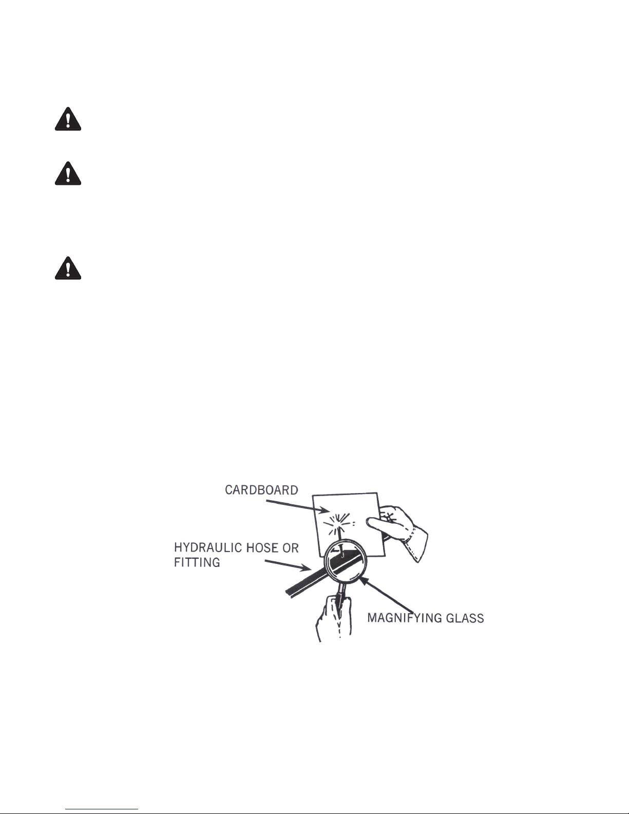
WARNING! USE CARE WITH HYDRAULIC FLUID PRESSURE
Hydraulic uid under pressure can penetrate the skin and cause serious injury or death.
Hydraulic leaks under pressure may not be visible. Before connecting or disconnecting
hydraulic hoses, read your prime movers operator’s manual for detailed instructions on
connecting and disconnecting hydraulic hoses or ttings.
• Keep unprotected body parts, such as face, eyes, and arms as far away as possible from
a suspected leak. Flesh injected with hydraulic uid may develop gangrene or other
permanent disabilities.
• If injured by injected uid, see a doctor at once. If your doctor is not familiar with this type
of injury, ask him to research immediately to determine proper treatment.
• Wear safety glasses, protective clothing, and use a sound piece of cardboard or wood
when searching for hydraulic leaks.
DO NOT USE YOUR HANDS!
SEE ILLUSTRATION.
6

GENERAL SAFETY PRECAUTIONS
WARNING! DO NOT MODIFY MACHINE OR ATTACHMENTS
Modications may weaken the integrity of the attachment and may impair the function,
safety, life and performance of the attachment. When making repairs, use only the
manufacturer’s genuine parts, following authorized instructions. Other parts may be
substandard in t and quality. Never modify any ROPS (Roll Over Protection System)
equipment or device. Any modications must be authorized in writing by the manufacturer.
WARNING! SAFELY MAINTAIN AND REPAIR EQUIPMENT
•Do not wear loose clothing, or any accessories that can catch in moving parts. If you have
long hair, cover or secure it so that it does not become entangled in the equipment.
•Work on a level surface in a well-lit area.
•Use properly grounded electrical outlets and tools.
•Use the correct tool for the job at hand. Make sure they are in good condition for the task
required.
•Wear the protective equipment specied by the tool manufacturer.
WARNING! SAFELY OPERATE EQUIPMENT
Do not operate equipment until you are completely trained by a qualied operator in how to
use the controls, know its capabilities, dimensions, and all safety requirements. See your
prime movers manual for these instructions.
•Keep all step plates, grab bars, pedals, and controls free of dirt, grease, debris, and oil.
•Never allow anyone to be around the equipment when it is operating.
•Do not allow riders on the attachment or the prime mover.
•Do not operate the equipment from anywhere other than the correct operators position.
•Never leave equipment unattended with the engine running or with this attachment in a
raise position.
•Do not alter or remove any safety feature from the prime mover or this attachment.
•Know your work site safety rules as well as trafc rules and ow. When in doubt on any
safety issue, contact your supervisor or safety coordinator for an explanation.
7

EQUIPMENT SAFETY PRECAUTIONS
WARNING! REMOVE PAINT BEFORE WELDING OR HEATING.
Hazardous fumes/dust can be generated when paint is heated by welding, soldering or
using a torch. Do all work outside or in a well ventilated area and dispose of paint and
solvent properly. Remove paint before welding or heating.
When sanding or grinding paint, avoid breathing the dust. Wear an approved respirator.
If you use solvent or paint stripper, remove stripper with soap and water before welding.
Remove solvent or paint stripper containers and other flammable material from area. Allow
fumes to disperse at least 15 minutes before welding or heating.
WARNING! END OF LIFE DISPOSAL.
At the completion of the useful life of the unit, drain all fluids and dismantle by separating the
different materials (rubber, steel, plastic, etc.). Follow all federal, state and local regulations
for recycling and disposal of the fluid and components.
\WARNING! KNOW WHERE UTILITIES ARE
Observe overhead electrical and other utility lines. Be sure equipment will clear them.
When digging, call your local utilities for location of buried utility lines, gas, water, and
sewer, as well as any other hazard you may encounter.
DANGER! ROTATING OBJECTS
• Never allow anyone to reach into, kick into, or otherwise come in contact with a
rotating auger or with a non-rotating clogged auger. The auger can crush and/or
dismember. Keep everyone clear of the auger until the prime mover engine is off and
the hydraulic pressure has been relieved.
• Never allow anyone to reach into the chute, force objects (i.e. bars, poles, etc.) down
the chute, kick into the fan, or otherwise come in contact with a rotating fan or with
a non-rotating clogged fan. The fan can throw objects at a lethal speed and can
dismember. Keep everyone clear of the fan until the prime mover engine is off and the
hydraulic pressure has been relieved.
CAUTION! AVOID ELECTRICAL SHOCK
• To avoid electrical shock during the wiring harness installation, remove the ground
cable from the battery of your prime mover.
• Be aware that turning off the prime mover key does not cut the power to the chute
rotation motor or to the chute deflector actuator. With the switches for these devices
being powered 100% of the time, care must be taken to not engage these switches:
• accidentally at any time, especially when entering or leaving the prime mover
operator's position, or
• when others are working on or near the actuator, the deflector, the chute, or
any other part of this product that could cause personal injury if the switch or
switches are engaged.
• Avoid pinch points and be aware of rotating parts when manually turning the fan or
auger.
8
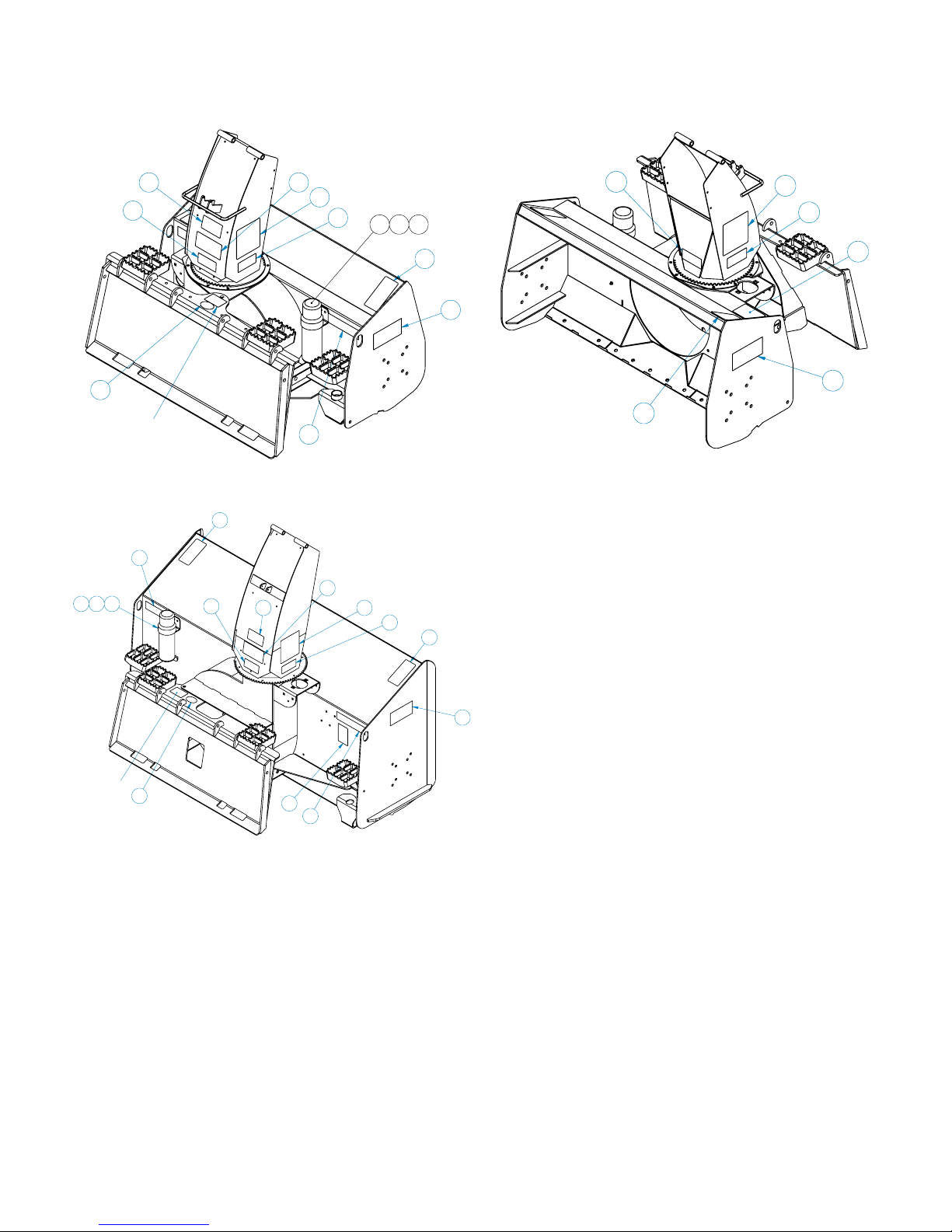
SAFETY DECAL LOCATIONS
5
13
5
12
9
3
10
13
5
5
6
11
12
9
3
10
Serial Tag
Location
4
12
178
HIGH FLOW
STANDARD FLOW
5
12
9
13
5
12
13
5
3
9
11
5
Serial Tag
Location
6
4
13
5
1 7 8
12
9
10
Standard Flow
12
10
178
Serial Tag
Location
11
5
6
3
HIGH FLOW
4
13
5
10
12
Item Part Qty Description
1. 07-6869 1 Manual Holder
3. 50-0724 1 Decal, Warning, High Pressure Fluid
4. 50-0727 1 Decal, Warning, Flying Objects
5. 50-0737 3 Decal, Warning, Pinch Point Hazard
6. 50-10017 1 Decal, Warning Avoid Serious Injury
7. P100403 2 Screw, HHC, Gr5 1/4-20 x 3/4
8. P158003 2 Nut, Elastic Lock, 1/4
9
9. RDL3118 2 Decal, Logo, FFC, Medium
10. RDL3131 2 Red Reflective Tape, 2 x 6
12. RDL3161 2 Decal, Warning, Auger
13. RDL3163 2 Decal, Danger Rotating Fan
5
High Flow
INSTRUCTIONS
• Keep all safety signs clean and legible.
• Replace all missing, illegible, or damaged safety signs.
• Replacement parts for parts with safety signs attached must also have safety signs attached.
• Safety signs are available, free of charge, from your dealer or from FFC.
PLACEMENT OR REPLACEMENT OF SAFETY SIGNS
1. Clean the area of application with non-flammable solvent, and then wash the same area with soap
and water.
2. Allow the surface to fully dry.
3. Remove the backing from the safety sign, exposing the adhesive surface.
4. Apply the safety sign to the position shown in the diagram above and smooth out any bubbles.
9
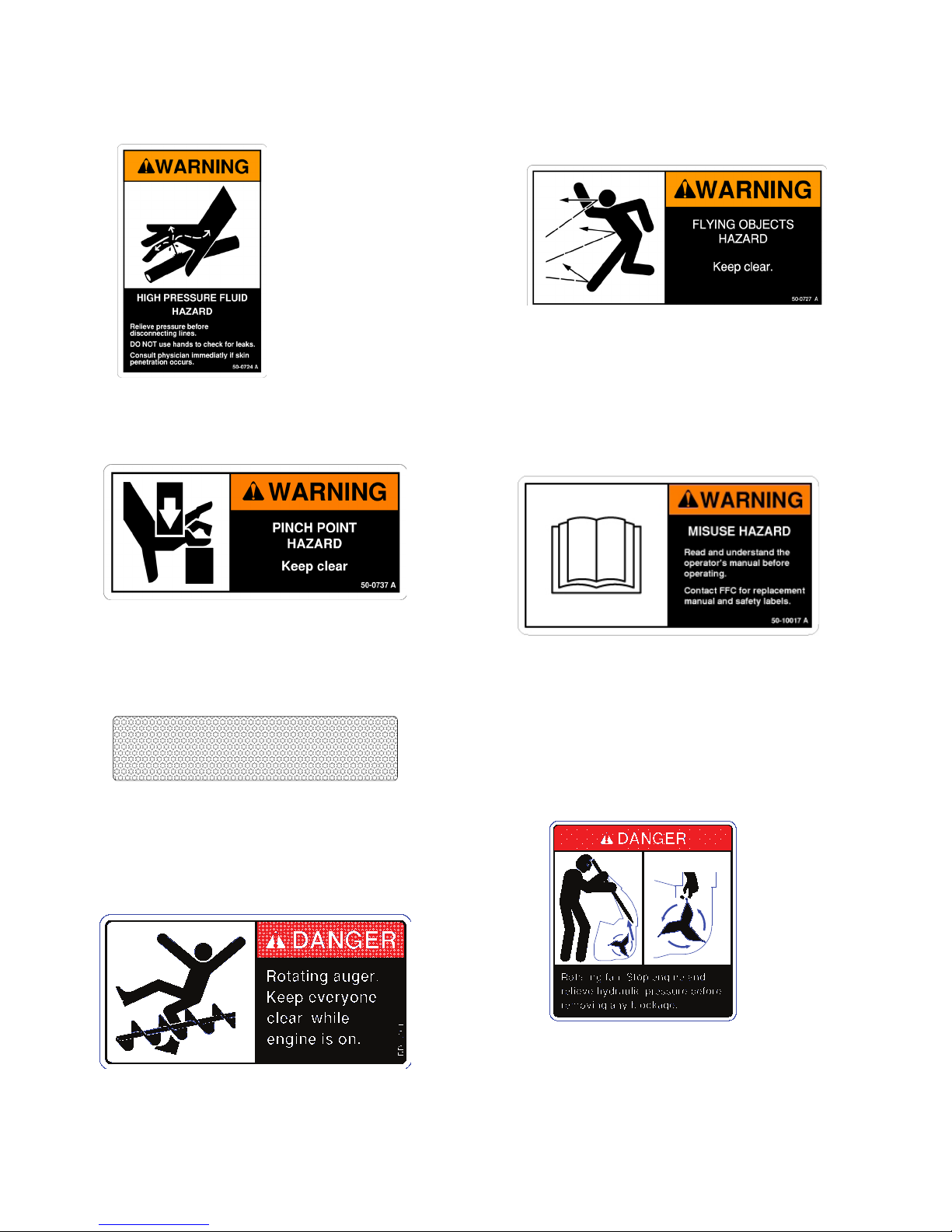
SAFETY DECALS
3. 50-0724
WARNING! HIGH PRESSURE FLUID
4. 50-0727
WARNING! FLYING OBJECTS
5. 50-0737
WARNING! PINCH POINT
10. RDL3131
RED REFLECTIVE MARKER
6. 50-10017
WARNING! READ MANUAL
13. RDL3163
DANGER! ROTATING FAN
12. RDL3161
DANGER! ROTATING AUGER
10

INSTALLATION & SET-UP
WARNING! READ MANUAL PRIOR TO INSTALLATION
Improper installation, operation, or maintenance of this equipment could result in
serious injury or death. Operators and maintenance personnel should read this
manual, as well as all manuals related to this equipment and the prime mover
thoroughly before beginning installation, operation, or maintenance. FOLLOW ALL
SAFETY INSTRUCTIONS IN THIS MANUAL AND THE PRIME MOVER'S MANUAL(S).
1. Place this product on a firm, level surface that is large enough to safely accommodate this
product, your prime mover and all workers involved in the mounting process.
2. Refer to the operator’s manual(s) for your prime mover, loader, and quick-attach and follow the
mounting instructions contained therein.
3. Carefully raise the loader and cycle the tilt cylinders to check clearances and to verify that all
mounting procedures have been successfully completed.
NOTICE! Lubricate all grease fittings before connecting this product to your prime
mover's hydraulic system. Refer to HYDRAULIC SNOW BLOWER
MAINTENANCE and follow the instructions
WIRING HARNESS INSTALLATION
MATERIALS NEEDED: Nylon cable ties
1. Park your prime mover on a level surface with this product properly attached.
2. Place your prime mover's transmission in "Park" and engage the parking brake.
3. Lower this product onto the level surface.
4. Shut off your prime movers engine, remove the starter key, wait for all moving parts to come to
a stop, and relieve all pressure in the hydraulic lines.
5. Attach the control box to the left side screen of your prime mover's roll-over protective structure
(ROPS). Use the magnet on back of the control box to secure the control box so that the box is
flat against the screen, the toggle switches are on the top, and the wiring harness cables are
on the bottom.
WARNING! Failure to obey the following procedures could result in death or serious injury.
• Before doing any work on your prime mover's battery, read and understand
all prime mover instructions and safety signs for your prime mover's electrical
system. Pay special attention to hazard avoidance and remedial action related
to explosive gas and acid.
11

INSTALLATION & SET-UP
CAUTION! Failure to obey the following procedures may result in personal injury.
• To avoid electrical shock during the wiring harness installation, remove the
ground cable from the battery of your prime mover.
6. Remove the ground cable from the negative (-) post of your prime mover's battery.
7. Remove the nut from the POSITIVE (+) cable clamp on the battery and slide the RED wire ring
terminal from the wiring harness cable over the positive (+) cable clamp bolt. Secure the ring
terminal with the nut.
8. Remove the nut from the NEGATIVE (-) cable clamp on the ground cable and slide the BLACK
wire ring terminal from the wiring harness cable over the negative (-) cable clamp bolt.
9. Reinstall the ground cable on the negative post of the battery and secure the ring terminal and
the ground cable with the nut removed in the previous step.
10. Secure the wiring harness cable from the battery to the control box with your nylon cable ties.
11. Feed the wiring harness cable:
a) back to the left-rear area of your prime mover,
b) past the loader arm's rear hinge point by following the hydraulic hoses where possible, and
c) down the loader arm following the hydraulic lines.
12. Allow sufficient slack in the cable at the hinge point to provide for a full range of motion of the
loader arms. Use your nylon cable ties to secure the cable to the loader frame below the hinge
point and back to the control box.
HYDRAULIC SNOW BLOWER HYDRAULIC CONNECTION
READ AND UNDERSTAND ALL SAFETY STATEMENTS
Read all safety decals and safety statements in all manuals before beginning any Snow
Blower hydraulic connection. Know and obey all OSHA regulations, local laws, and other
professional guidelines for your operation. Know and follow good work practices when
assembling, maintaining, repairing, mounting, removing, or operating this equipment.
1. Disconnect the hydraulic hose quick couplers from one another and attach the quick couplers to
your prime mover as per the instructions in your prime mover's operator's manual.
(Also see Hydraulic Hose Connections in the SERVICE section.)
2. Carefully raise the loader and cycle the tilt cylinders to check hose clearances and to check for
any interference. Operate the chute and deflector on this product to make the same checks.
3. Cycle the hydraulic cylinder(s) on this product several times from fully retracted to fully extended
until all air has been completely removed from the cylinder(s).
WARNING! Do not lock the auxiliary hydraulics of your prime mover in the "ON" position.
Failure to obey this warning could result in death or serious injury.
12

INSTALLATION & SET-UP
READ AND UNDERSTAND ALL SAFETY STATEMENTS
Read all safety decals and safety statements in all manuals before beginning any Snow
Blower setup. Know and obey all OSHA regulations, local laws, and other professional
guidelines for your operation. Know and follow good work practices when assembling,
maintaining, repairing, mounting, removing, or operating this equipment.
SKID SHOE ADJUSTMENT
Determine what type of surface is beneath the snow where your Hydraulic Snow Blower is being
operated.
• If the surface is hard and smooth, like concrete or asphalt, the skid shoe placement as shipped
from the factory (i.e. in their highest position) is correct.
• If the surface is soft or uneven, then a lower position should be used.
Changing the position of the skid shoes should be performed as follows:
1. Park your prime mover on a level surface with this product properly attached.
2. Place your prime mover's transmission in "Park" and engage the parking brake.
3. Lower this product's cutting edge onto wood or steel blocking that is adequate to safely hold the
base of the skid shoes 2.5" to 3" off of the level surface OR tilt the snow blower forward (keeping
the loader arms locked to the attachment mounting plate), holding the skid shoes 2.5" to 3" off
the ground.
4. Shut off your prime mover's engine, remove the starter key, wait for all moving parts to come to a
stop, and relieve all pressure in the hydraulic lines.
13
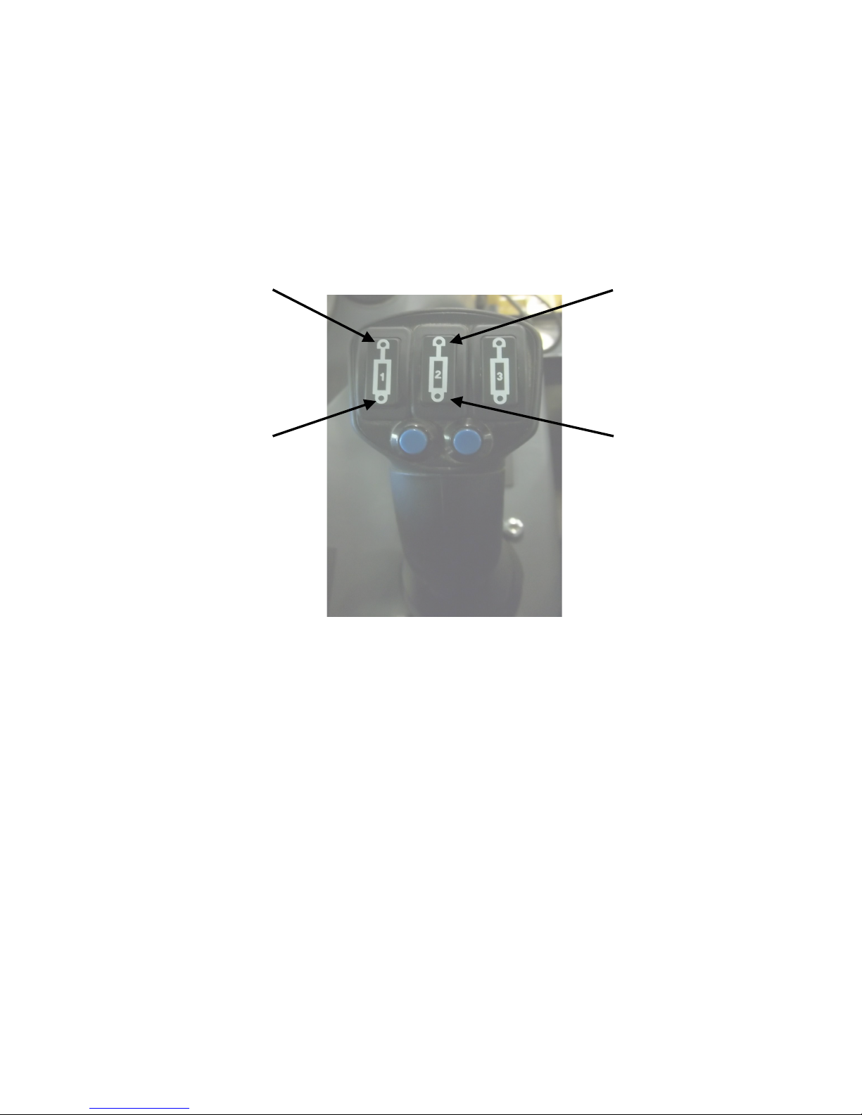
OPERATION
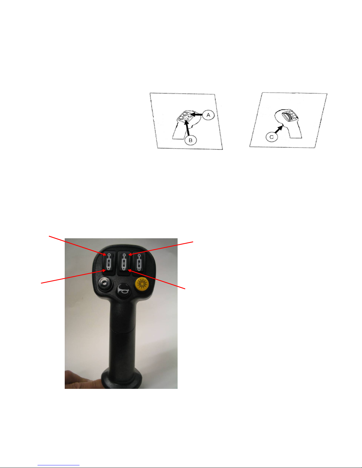
JOY STICK ILLUSTRATIONS
Caterpillar Joy Stick
Deflector UP: Button A
Deflector DOWN: Button B
Chute Rotation RIGHT: Button C & Button B
Chute Rotation LEFT: Button C & Button A
RIGHT JOYSTICKLEFT JOYSTICK
A
C
Gehl Joy Stick
B
D
Deflector UP: Button A
Deflector DOWN: Button B
Chute Rotation RIGHT: Button C
Chute Rotation LEFT: Button D
14
OPERATION
Gehl RT Track Loader Joy Stick
A
B
C
D
Chute Rotation LEFT: Button A
Chute Rotation RIGHT: Button B
Deflector UP: Button C
Deflector DOWN: Button D
15
 Loading...