

FF-Automation WSN169, WSN170, WSN225, WSN450, WSN470 Setup, Installation & Operating Manual
...Page 1
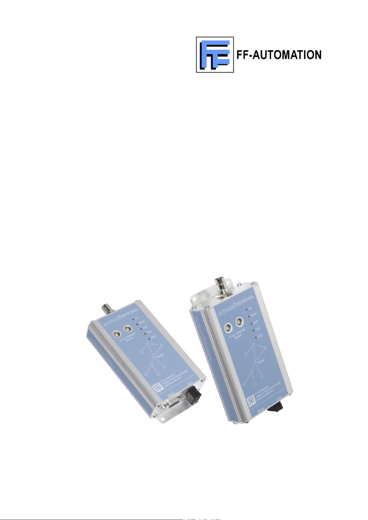
WSN SERIES
RADIO MODEMS
SETUP, INSTALLATION
&
OPERATING MANUAL
WSN Manual Page 1 of 34 Rev. G – 4 March 2007
Page 2

CONTENTS
1 INTRODUCTION ..................................................................................... 3
1.1 PRODUCTS COVERED .................................................................................................... 3
1.2 IMPORTANT NOTICES ..................................................................................................... 3
2 PRODUCT OVERVIEW .......................................................................... 4
2.1 GENERAL .......................................................................................................................... 4
2.2 TRANSMITTER .................................................................................................................. 4
2.3 RECEIVER ......................................................................................................................... 4
2.4 MPU CONTROL ................................................................................................................. 5
2.5 PROGRAMMING & CONFIGURATION ............................................................................. 5
2.6 SOFT MODEM: .................................................................................................................. 5
2.7 MODES OF OPERATION .................................................................................................. 5
2.8 HANDSHAKING ................................................................................................................. 5
2.9 ADDITIONAL FEATURES ................................................................................................. 5
3 SPECIFICATIONS .................................................................................. 7
3.1 TECHNICAL SPECIFICATIONS ........................................................................................ 7
3.2 APPROVALS AND LICENSING ......................................................................................... 9
4 PRE-PROGRAMMED CHANNEL PLANS ........................................... 10
4.1 UK MPT1411/VNS2111 CHANNELS .............................................................................. 10
4.2 UK MPT1329 CHANNELS ............................................................................................... 12
5 SETUP & INTERFACING ..................................................................... 13
5.1 INTERNAL CONSTRUCTION.......................................................................................... 13
5.2 INTERFACE PORT PIN CONNECTIONS ....................................................................... 13
5.3 12VDC POWER ............................................................................................................... 15
5.4 ANTENNA PORT ............................................................................................................. 15
5.5 CHANNEL SWITCHES .................................................................................................... 15
5.6 PROGRAMMING ............................................................................................................. 15
5.7 RF POWER ...................................................................................................................... 15
5.8 TIME-OUT-TIMER ........................................................................................................... 15
5.9 INTERNAL MODEM ......................................................................................................... 16
5.10 RADIO DATA FORMATS ................................................................................................. 16
5.11 FORWARD ERROR CORRECTOR ................................................................................. 17
5.12 SQUELCH TAIL (DRIBBLE BITS) ELIMINATION ............................................................ 17
5.13 SERIAL INTERFACE & HANDSHAKING ........................................................................ 17
5.14 TRAFFIC PROTOCOL & ROUTING MODES .................................................................. 19
5.15 TRANSMIT & RECEIVE TIMING ..................................................................................... 20
5.16 POWER CONSUMPTION ................................................................................................ 23
5.17 POWER SAVE MODE ..................................................................................................... 23
5.18 “RSSI” RECEIVE SIGNAL STRENGTH INDICATION ..................................................... 23
5.19 STATUS LEDS................................................................................................................. 24
6 STORE & FORWARD........................................................................... 25
6.1 STORE & FORWARD BASED ON CLIENT PROTOCOL. ............................................... 25
6.2 MODBUS ......................................................................................................................... 25
6.3 RFT ROUTING PROTOCOL............................................................................................ 27
7 INSTALLATION .................................................................................... 30
7.1 INTRODUCTION .............................................................................................................. 30
7.2 POWER SUPPLIES ......................................................................................................... 30
7.3 EFFECTIVE RADIATED POWER (ERP) ......................................................................... 30
7.4 ANTENNAS, COAX FEEDERS & PERIPHERALS .......................................................... 31
7.5 MOUNTING & INSTALLATION ........................................................................................ 33
7.6 FIXING DETAILS ............................................................................................................. 33
WSN Manual Page 2 of 34 Rev. G – 4 March 2007
Page 3

1 INTRODUCTION
1.1 PRODUCTS COVERED
This manual covers the WSN Series of low cost, high performance radio modems designed for
data applications in commercial and industrial systems.
The WSN is an advanced, simplex/half-duplex, data radio for transmission of serial data.
Versions are available with three different serial port configurations:-
A true RS232 interface full handshaking.
As above but with 5V TTL voltage levels on the interface rather than RS232 levels.
An RS232/RS422/RS485 interface with software selection of required mode. (RTS/CTS
and DSR/DTR Handshaking lines looped back to each other in RS232 mode)
Information is provided to assist with configuration, installation, and operation of the products in
point to point or point to multi-point applications. A separate programming manual covers the
use of the associated WinA4P software for programming and configuration of the radios.
Component level servicing is not covered in this document; if the product fails its first line testing
it should be returned to a service centre.
1.2 IMPORTANT NOTICES
1.2.1 Copyright
All rights to this manual are the sole property of FF-Automation Oy The copying of the manual
in whole or in part by any method without written permission is strictly prohibited.
1.2.2 Right To Change
In the interest of improvement, R.F. Technologies reserves the right to change the technical
specifications or functions of its product without notice.
1.2.3 Software
FF-Automation Oy software is delivered “as is”. FF-Automation Oy does not grant any kind of
warranty or guarantees on its saleability or it’s suitability for use in specific applications.
Under no circumstances is R.F. Technologies liable for any damages arising from using the
software.
The copyrights relating to all software is the sole property of FF-Automation Oy.
Any coping, editing, translating or modifying is strictly forbidden without prior written consent
from FF-Automation Oy.
1.2.4 Safety Critical Applications
The WSN has not been designed for, nor is it intended for, use in safety critical or life support
applications. No functional warranty is given if the product is used in such applications.
1.2.5 Use
The WSN radio modems have been designed to work on various licensed and license-free
frequency bands in use around the world. In the license-free bands, the user must ensure that
the radio modem is used under the terms & conditions applicable to the use of the bands
concerned.
In licensed bands, the user must obtain permission and the necessary licenses from the
relevant authorities.
WSN Manual Page 3 of 34 Rev. G – 4 March 2007
Page 4

2 PRODUCT OVERVIEW
2.1 GENERAL
The WSN Series has been designed as a range of high specification, low cost radio modems for
stand-alone applications or for integration into OEM products.
Through the use of advanced DSP technology, the design has been optimised for reliability and
low current consumption, making the WSN suitable for operation on remote sites without mains
power.
Applications include security, command & control, data logging, SCADA, telemetry, remote
switching or any similar applications where serial data needs to be transmitted.
The WSN is available with three different serial interfaces:-
An RS232 interface with all signalling lines to allow full handshaking if required.
A TTL version of the unit, which uses 5V TTL voltage, levels on the serial interface
connector rather than RS232 signalling levels, but is otherwise the same.
A version with an RS232/RS422/RS485 interface. Required interface mode is selected
using the configuration software. In RS232 mode, the RTS line is looped back to CTS
and the DSR line is looped back to DSR. RS422/RS485 half-duplex (2-wire) or full
duplex (4-wire) modes are both supported.
The data rate on the serial interface can set to a range of values from 150 baud to 38,400 baud,
while the over-air data rate can be independently set to a range of values between 150 baud
and 9,600 baud. If high throughput speeds are not required, the modem can be set to a slower
over-air rate to take advantage of the associated improvement in receiver threshold.
The WSN is available with two different transmit powers. The low power version meets the
licence-exempt ETS300-220 specification while the higher power 5W version meets the tougher
ETS300-113 and the USA and Canadian specifications.
2.2 TRANSMITTER
The transmitter frequency can be user programmed anywhere within it’s pre-aligned bandwidth.
There are two power versions available, 10mW to 750mW and 50mW to 5W. The transmit
power of any particular hardware version can be set accurately within the relevant range under
software control.
2.3 RECEIVER
The receiver is a very low current double conversion superheterodyne with an active balanced
mixer for very good intermodulation performance. Careful attention to spurious response,
adjacent channel and blocking performance, makes the product ideal for crowded telemetry
channels.
To achieve high performance the programmable bandwidth of the receiver has been limited (for
UHF it is 10MHz, + 5MHz from centre frequency), full details are in the technical specification
section.
Should re-alignment be required, the unit can be returned to our service centre.
WSN Manual Page 4 of 34 Rev. G – 4 March 2007
Page 5

2.4 MPU CONTROL
The Microprocessor (MPU) is the heart of the product and at the centre is a 128k flash
microprocessor that controls all the interface circuits to the radio module and external
input/outputs. As well as the control function, the processor provides DSP functionality that
enables modem operation between 150 and 9,600bps. The processor has 128k of flash
memory from which the code is executed and internal EEPROM for storing programmed
parameters.
2.5 PROGRAMMING & CONFIGURATION
The parameters of the WSN are PC programmable via the serial port. Full details of all the
programmable parameters are covered in the separate programming manual. Details of cables
and adaptors needed for the various interface versions are given in Section 5.6.
2.6 SOFT MODEM:
The WSN has a “soft modem” which allows over-air transmission at rates between 150bps and
9,600bps using a range of different modulation schemes. The over-air rate can be selected by
the operator to optimise link performance.
2.7 MODES OF OPERATION
2.7.1 Transparent Operation
The WSN can operate transparently without packetising the data and without adding any other
overheads, thereby maximising data throughput rates. It requires no knowledge of the data it is
transmitting. Data is simply transmitted and received with minimal delay.
2.7.2 Protocol specific modem
The radio recognises a complete frame and only transmits and receives data conforming to that
format. No addressing of radios or routing of data is performed. Protocols such as MODBUS &
DNP3 can be supported in this way.
2.7.3 Routing modem
The radios recognise a protocol specific frame and the address to which the frame is to be sent.
Routing information must be stored in each radio for each destination address that requires the
use of repeaters. Any radio in the system can operate as a repeater. The radio does not
perform any acknowledgement or retries. Any protocol using a fixed address field such as
MODBUS can be supported.
2.8 HANDSHAKING
On the RS232 Full Handshaking and TTL versions, transmission control can either use RTS
control signals or be configured for automatic initiation of transmission on receipt of serial data
at the traffic interface. In either case, the radio provides a CTS output, which can optionally be
used for flow control.
On the RS232/RS422/RS485 version, transmission is automatic when transmit data is applied.
The DSR line is internally looped back to DSR and, when configured for RS232 mode, the RTS
line is also looped back to CTS.
In all versions, the radio incorporates a 1,024 byte internal buffer to cope with situations where
the interface data rate is higher than the over-air rate.
2.9 ADDITIONAL FEATURES
The WSN incorporates the following additional features which enhance the usability of the
product and assist with the operation and maintenance of systems using the product:-
2.9.1 Status LEDs:
The WSN Radio Modems have a number of front panel LED’s to enable the operator to see at a
WSN Manual Page 5 of 34 Rev. G – 4 March 2007
Page 6

glance the status of the product and the serial data port.
2.9.2 Time-out Timer
The transmitter within the WSN has a user programmable time-out timer which allows the
maximum continuous transmission time to be set in order to prevent channel blocking due to a
fault.
2.9.3 Power-Save Modes
The WSN has both internally controlled and externally controlled power-save modes to reduce
overall power consumption to extremely low levels for operation on sites without mains power.
2.9.4 Squelch Tail Elimination
As a user programmable option, the WSN can also operate in a packetisation mode where
framing characters are added at the start and end of the user's message prior to transmission
and stripped off again at the receive end prior to passing the user data to the interface
connector. This can be useful in getting rid of any spurious characters which may otherwise be
generated at the end of messages by squelch noise as the receiver mutes and which can affect
old or non-tolerant protocols.
In a high interference environment, enabling packetisation will often help to block reception of
the interfering signals.
2.9.5 Forward Error Correction
The WSN allows an optional forward error correction to be switched in when the over-air data
rate is 9,600bps. This will improve error performance, but there is an associated data
throughput overhead of around 30%, which therefore reduces the effective transmission rate for
the user data. The forward error corrector is not available at lower data rates, as it offers no
significant performance enhancement at these lower rates.
WSN Manual Page 6 of 34 Rev. G – 4 March 2007
Page 7

3 SPECIFICATIONS
3.1 TECHNICAL SPECIFICATIONS
3.1.1 General
Frequency Range: WSN169/170 138 - 175MHz
WSN225 175 - 225MHz
WSN450/470 406 - 512MHz
WSN869 869 - 870MHz
(50MHz – 950MHz to special order)
Power Requirements: 12VDC (10V – 15.5DC)
Standby: <75uA
Receiver on & decoding: <70mA
Transmitting: 300mA to 2.1A dependent on Tx power
Number of Channels: 80 sequential or 32 discrete user programmable channels.
Min. Programmable
Channel Step: 6.25kHz or 5kHz
Channel Spacing: 12.5kHz, 20kHz or 25kHz
Operating Temp.
Stability: 2ppm –30 to +60ºC
Construction: Aluminium enclosure.
Size: 75mm W x 130mm L x 30mm H (excluding brackets and connectors)
Mounting: Screws to a flat surface.
Weight: 250g
Connectors: DC Power 2-way Klippon Type
Serial Data 9-way D-Type Female
RF BNC (50 ohm)
LED Indicators: TX, Busy, System, RXD, TXD
3.1.2 Transmitter:
RF Output Power: WSN 169/450/869 10mW - 750mW
WSN 170/225/470 50mW - 5Watts
Bandwidth: VHF 10MHz without re-alignment
UHF 12MHz without re-alignment
869 30MHz without re-alignment
Internal Modulation: Programmable for FFSK, 2-Level FSK, GMSK or 4-Level FSK.
Max. Deviation: ± 7.5kHz max
Duty Cycle up to 70%
Adj. Channel Power: >65dB at 12.5kHz
Spurious Emissions: As per ETS300-113
Rise Time: < 9mS
3.1.3 Receiver
Sensitivity: 0.25uV (-119dBm) for 12dB SINAD de-emphasised
0.355uV (-117dBm) for 12dB SINAD flat
Bandwidth: VHF 5MHz without re-alignment
UHF 10MHz without re-alignment
WSN Manual Page 7 of 34 Rev. G – 4 March 2007
Page 8

869 20MHz without re-alignment
Spurious Response: WSN 169/450/869 >65dB
WSN 170/225/470 >70dB
Blocking: WSN 169/450/869 >85dBuV
WSN 170/225/470 >90dBuV
Intermodulation: WSN 169/450/869 >60dB (3 Signal)
WSN 170/225/470 >65dB (3 Signal)
Adjacent Channel: >65dB at 12.5kHz
IF Frequencies: 45MHz and 455kHz
Spurious Emissions: WSN 169/450/869 <ETS 300-220
WSN 170/225/470 <ETS 300-113
Mute Response Time: <2msec
3.1.4 Internal Modem
Serial Comms: Asynchronous (or Synchronous with custom software).
Baud rate programmable between 150bps and 38,400bps
Interface: /232Full version :- RS.232 complete with signalling lines
/TTL version:- 5V TTL levels rather than RS.232
/232+485 version:- RS.422/RS.485 (2 or 4 wire) or
RS232 with looped back signalling lines.
Parity: Programmable as Odd, Even or None
NRZI: On or Off
Stop bits: Programmable 1 or 2
Data Bits: Programmable 7 or 8
Signalling Formats: Programmable as V23, Bell202 or MPT1327, up to 1200 baud, coherent
Synchronous/Async. Programmable as either up to 1200bps, synchronous above 1200bps
Over-air Baud Rate: 150 – 9600bps within 12.5kHz
Bit Error Rate: 150 - 2400 baud less than 1 x 10⁻³ at –120dBm
4800 baud less than 1 x 10⁻³ at –117dBm
9600 baud less than 1 x 10⁻³ at –115dBm (FEC on)
9600 baud less than 1 x 10⁻³ at –112dBm (FEC off)
Forward Error Corrector (FEC) is a programmable option at 9600bps.
The bit error rates quoted above are for fixed messages representing
FFSK at 2400 baud, GMSK at 4800 baud, 4 Level FSK at 9600 baud.
typical data sent over the link. The BER should not be directly compared
with other manufactures figures unless the data format is known, as
many manufacturers quote a BER based on a simple alternating data
pattern, which will generally give much better BER results.
WSN Manual Page 8 of 34 Rev. G – 4 March 2007
Page 9
3.2 APPROVALS AND LICENSING
The WSN has been designed to meet the relevant standards outlined below. Should others be
required, please contact the sales office.
3.2.1 UK Approvals
MPT1411/VNS2111: The 5W version of the WSN has been tested to MPT1411 and the
replacement VNS2111 for licensed applications with a maximum data
rate of 9600bps within a 12.5 kHz channel. A licence is required and the
permitted output power is normally stated on the licence.
MPT1329: The radios meet the requirements of MPT1329
BS2011: The unit complies with the Vibration specification BS2011.
3.2.2 European Approvals
ETS 300-220 The unit meets the specification for European licensed exempt
communications with a maximum RF power level of 500mW. Please
note the permitted power level may vary from country to country.
ETS 300-113 The 5W version of the unit meets the specification for licensed data
radios
ETS 301-489: The unit meets the required CE specification and carries a CE Mark.
EN60950 The unit meets the relevant requirements of this Safety specification.
3.2.3 European Declaration of Conformance
Hereby, FF-Automation Oy declares that the WSN Series of Radio Modems is in compliance
with the essential requirements and other relevant provisions of Directive 1999/5/EC.
In the interest of improvement the above specifications are subject to change without notice.
WSN Manual Page 9 of 34 Rev. G – 4 March 2007
Page 10

4 PRE-PROGRAMMED
CHANNEL
SCANNER
OUTSTATIONS
1
457.50625
463.00625
2
457.51875
463.01875
3
457.53125
463.03125
4
457.54375
463.04375
5
457.55625
463.05625
6
457.56875
463.06875
7
457.58125
463.08125
8
457.59375
463.09375
9
457.60625
463.10625
10
457.61875
463.11875
11
457.63125
463.13125
12
457.64375
463.14375
13
457.65625
463.15625
14
457.66875
463.16875
15
457.68125
463.18125
16
457.69375
463.19375
17
457.70625
463.20625
18
457.71875
463.21875
19
457.73125
463.23125
20
457.74375
463.24375
21
457.75625
463.25625
22
457.76875
463.26875
23
457.78125
463.28125
24
457.79375
463.29375
25
457.80625
463.30625
26
457.81875
463.31875
27
457.83125
463.33125
28
457.84375
463.34375
29
457.85625
463.35625
30
457.86875
463.36875
31
457.88125
463.38125
32
457.89375
463.39375
33
457.90625
463.40625
34
457.91875
463.41875
35
457.93125
463.43125
36
457.94375
463.44375
37
457.95625
463.45625
38
457.96875
463.46875
39
457.98125
463.48125
40
457.99375
463.49375
41
458.00625
463.50625
42
458.01875
463.51875
43
458.03125
463.53125
44
458.04375
463.54375
CHANNEL PLANS
Using the PC configuration software, the WSN can be programmed with a number of standard
channel plans. These currently include all UK MPT1411 or MPT1329 channels. Further
standard channel plans may become available in later releases of the configuration software. A
mixture of channels from different channel plans can also be entered discretely using the
software.
The following tables show the channel numbers and associated frequencies for various channel
plans:-
4.1 UK MPT1411/VNS2111 CHANNELS
WSN Manual Page 10 of 34 Rev. G – 4 March 2007
Page 11

45
458.05625
463.55625
46
458.06875
463.56875
47
458.08125
463.58125
48
458.09375
463.59375
49
458.10625
463.60625
50
458.11875
463.61875
51
458.13125
463.63125
52
458.14375
463.64375
53
458.15625
463.65625
54
458.16875
463.66875
55
458.18125
463.68125
56
458.19375
463.69375
57
458.20625
463.70625
58
458.21875
463.71875
59
458.23125
463.73125
60
458.24375
463.74375
61
458.25625
463.75625
62
458.26875
463.76875
63
458.28125
463.78125
64
458.29375
463.79375
65
458.30625
463.80625
66
458.31875
463.81875
67
458.33125
463.83125
68
458.34375
463.84375
69
458.35625
463.85625
70
458.36875
463.86875
71
458.38125
463.88125
72
458.39375
463.89375
73
458.40625
463.90625
74
458.41875
463.91875
75
458.43125
463.93125
76
458.44375
463.94375
77
458.45625
463.95625
78
458.46875
463.96875
79
458.48125
463.98125
80
458.49375
463.99375
WSN Manual Page 11 of 34 Rev. G – 4 March 2007
Page 12

CHANNEL
FREQUENCY
1
458.5000 Guard Ch.
2
458.5125
3
458.5250
4
458.5375
5
458.5500
6
458.5625
7
458.5750
8
458.5875
9
458.6000
10
458.6125
11
458.6250
12
458.6375
13
458.6500
14
458.6625
15
458.6750
16
458.6875
17
458.7000
18
458.7125
19
458.7250
20
458.7375
21
458.7500
22
458.7625
23
458.7750
24
458.7875
25
458.8000
26
458.8125
27
458.8250 Not Used
28
458.8375 Not Used
29
458.8500
30
458.8625
31
458.8750
32
458.8875
33
458.9000 Not Used
34
458.9125
35
458.9250
36
458.9375
37
458.9500 Guard Ch.
4.2 UK MPT1329 CHANNELS
The WSN can be programmed to operate on the full MPT1329 band of channels with access to
channels 26, 27 & 32 denied, in line with MPT1329 band plan.
The radio should be programmed for a maximum power level of 500mW.
WSN Manual Page 12 of 34 Rev. G – 4 March 2007
Page 13
1. DCD: Data Carrier Detect - - - o
2. RXD: Receive Data - - - - - - -
o- - - - - 6. DSR: Data Set Ready
o
o- - - - - 7.
3.
o- - - - - 8.
4. DTR: Data Terminal Ready - - o
o- - - - - 9. nc Not Connected
5.
RTS: Request to Send
TXD: Transmit Data - - - - - - - o
CTS: Clear to Send
GND: GROUND - - - - - - - - - - o
5 SETUP & INTERFACING
5.1 INTERNAL CONSTRUCTION
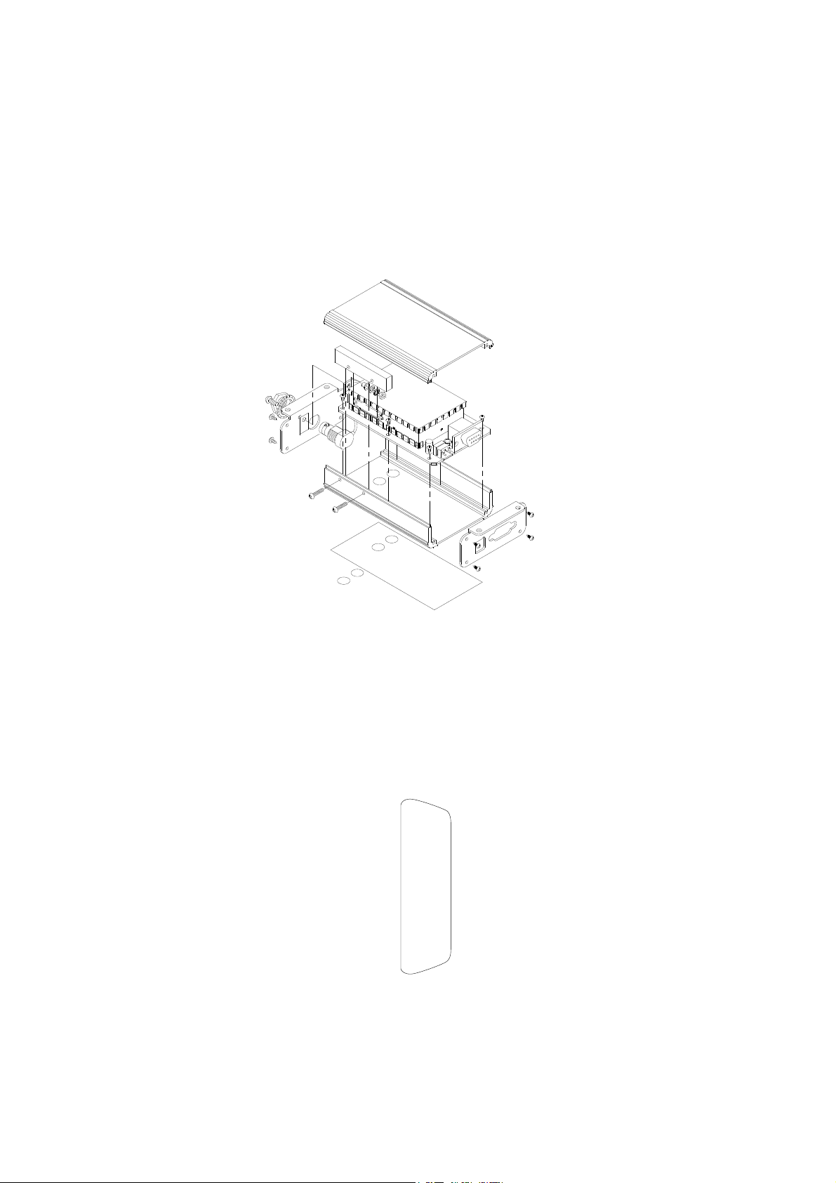
The exploded view shows the main components of the radio modem. There are no user
adjustments or settings, which require removal of the covers.
5.2 INTERFACE PORT PIN CONNECTIONS
The WSN Series is equipped with a 9 way female D connector for the traffic interface. The pins
of this connector are allocated as follows:-
5.2.1 RS232-Only (Full Handshaking) and 5V TTL versions
WSN Manual Page 13 of 34 Rev. G – 4 March 2007
Page 14

5.2.2 RS232/RS422/RS485 Versions
o- - - - - 9. nc Not Connected
o- - - - - 8. CTS: Clear to Send
(Internally connected to Pin 7)
- - - - - 7. RTS: Request to Send
o(Internally connected to Pin 8)
2. : Receive Data Output - - - - - - - - RXD o
o- - - - - 6. DSR: Data Set Ready
(Internally connected to Pin 4)
o- - - - - 9. nc Not Connected
o- - - - - 8. *****: Do Not Use
(Internally connected to Pin 7)
- - - - - 7. : -ve Data In to Radio
o TXD -
(Internally connected to Pin 8)
2. : -ve Data Out from radio - - - - - - RXD - o
o- - - - - 6. DSR: Data Set Ready
(Internally connected to Pin 4)
The RS232/RS422/RS485 versions of the WSN may be software programmed to have either an
RS232 or an RS422/RS485 compatible interface.
To allow programming without an interface adapter, a radio programmed for RS422/RS485
operation will switch back to RS232 operation if the front panel rotary switches are set to
position 00 to select programming mode. Note that although the WSN can withstand RS232
voltages on its inputs in RS422/RS485 mode, this may not be the case for externally connected
devices. To avoid any risk of damage to the externally connected equipment, care must
therefore be taken to ensure that programming mode is not selected while connected to
RS422/RS485 terminal equipment.
Pin allocation when set for RS232 operation:-
Pin allocation when set for RS422/RS485 operation:-
When half-duplex (2-wire) RS422/RS485 operation is programmed, the TXD- and TXD+ signals
are internally connected to the RXD- and RXD+ signals respectively. The 2-wire half-duplex
bus only needs to be connected to the RXD- and RXD+ pins (Pins 1 and 2). Shorting links are
not required in the connector.
When operating in 2-wire RS422/RS485 mode, the radio will output data on to a 2 wire circuit
whenever it is received, which could lead to a bus conflict in conditions of high interference and
prevent a connected terminal from outputting transmit data. To avoid this condition it is
recommended that the message packeting option is turned on at both ends of the radio link.
The DTR and DSR signals are looped back to each other internally in both configurations.
When configured for RS232 operation, the RTS and CTS signals are also looped back to each
other. The radio should in most circumstances operate correctly in applications requiring
RTS/CTS handshake although the it is unable to use CTS to prevent buffer overflow. Overflow
situations can easily be avoided by making the serial port baud rate the same as the radio
signal baud rate, or by ensuring that message sizes do not exceed the buffer size of 1024
bytes.
The DTR input has a threshold of approximately +1.5V with respect to ground, it may be used
with a standard RS232 level signal or a TTL level signal in either RS232 or RS485 mode, the
signal is active high in both cases.
WSN Manual Page 14 of 34 Rev. G – 4 March 2007
Page 15

5.3 12VDC POWER
A nominal 12VDC (9.6 – 15.5Vdc) is supplied to the unit via a 2 way pluggable terminal block,
the polarity is marked on the front panel and the plug has a polarity key to prevent accidental
polarity reversal. In the event of a polarity diodes and fuses protect reversal the circuit board.
5.4 ANTENNA PORT
The antenna connection is a 50-ohm BNC connector. This should be connected to a suitable
antenna or terminated in a 50-ohm load whenever the transmitter is activated. Transmission
into an open circuit may cause excessive current to be drawn from the supply and damage
could occur.
5.5 CHANNEL SWITCHES
The WSN can be user programmed with up to 80 sequential or 32 discrete simplex or semiduplex channels.
The two front panel BCD switches select the required channels or, if both are set to zero,
program mode is entered. In program mode, the radio interprets any signals on the serial
interface as programming commands rather than data for transmission.
When viewing a WSN with the aerial connector at the top, the left hand rotary switch is the
"tens" switch and the right is the "units" switch, thus to set channel 37, set the left switch to 3
and the right to 7.
5.6 PROGRAMMING
The parameters of the WSN can be programmed via the serial port using either DOS or
Windows based software. The individual configuration files can be stored on disc for future use
or printed. Full details of all the programmable parameters are covered in the separate
programming manual.
The RS232 Only (Full Handshaking) version can be connected directly to the serial port on a
PC using a straight-through cable.
The 5V TTL version needs an adaptor unit between the WSN and the programming computer to
convert between RS232 and TTL voltage levels.
The RS232/RS422/RS485 version does not need an adaptor because the serial port switches
to RS232 mode automatically when the radio is put into program mode by setting both front
panel switches to zero. A standard straight-through cable with all pins connected may be used
for connection to the PC.
5.7 RF POWER
The transmit power can be accurately set using a locally connected PC running the supplied
configuration software. This allows the RF power level to be programmed directly in Watts or
milliwatts with an accuracy of +/-1dB. There are no internal power adjustment points inside the
modem.
There are two transmit power ranges available. The low power WSN169, WSN450 & WSN869
versions can be set between 10mW and 750mW, while the higher power WSN170, WSN225 &
WSN470 versions can be set between 50mW and 5W.
5.8 TIME-OUT-TIMER
The transmitter within the WSN has a time-out timer, which allows the maximum continuous
transmission time to be set in order to prevent channel blocking due to a host fault. The timer
works in all modes (external/internal modem) and is programmable in one-second steps
between 0 and 255 seconds. If not required the timer can be programmed off.
If the timer is enabled and the selected time is exceeded, transmission will cease until the action
that normally causes transmission is removed and then re-applied. More explicitly, with
RTC/CTS handshake enabled RTS must be dropped and then raised again, or if handshake is
not enabled character transmission must be suspended for at least two character periods at the
serial port baud rate. In all modes the modem’s SYS led is flashed at least twice when time-out
occurs, the flashing continues while lockout is in force. The lockout timer is disabled if the
lockout time is set to 0. The lockout timer can be operated in “resettable” or “cumulative” mode,
WSN Manual Page 15 of 34 Rev. G – 4 March 2007
Page 16

in resettable mode the timer restarts each time a transmission is made, in cumulative mode the
timer counts up during transmit, and down during receive. If the timer counts up to the lockout
time during transmit, lockout occurs; this will eventually happen if the radio spends more than
half of its time transmitting. Lockout in this mode is indefinite and can only be reset by powering
the radio off.
5.9 INTERNAL MODEM
The WSN features an internal “soft modem” which offers unparalleled performance and
flexibility over a wide range of speeds and formats. Data is presented to the modem via the
RS232 (or TTL) serial connection at speeds between 150 and 38400 and then transmitted at
the programmed radio baud rate. Buffering is provided when the data rate is higher than the
radio transmission rate.
5.9.1 Modulation & Tone-sets
Within a 12.5kHz channel, the over-air transmission from the unit can be programmed for a
range of speeds. For 150, 300, 600,1200, the modulation is FFSK with Bell 202 and V.23
(Mode 2) tone-sets both supported. At these lower speeds, it is also possible to select a
protocol specific MPT1327 mode, which uses a 1200/1800Hz tone-set to allow compatibility
with number of additional modems from other manufacturers. At 2400bps the modulation is
coherent FFSK, at 4800bps it is GMSK and at 9600bps it is 4-Level FSK.
If operating at speeds up to and including 1200bps and compatibility with other equipment is not
required, the use of the Bell 202 tone-set is recommended, as this will give the best link
performance.
5.9.2 Synchronous/Asynchronous Modem Operation
The radio modem can be programmed for asynchronous or synchronous operation at baud
rates up to 1200. At baud rates of 2400 or more, modem operation may only be synchronous.
This relates to the over-air signal and has no bearing on the format of the data presented at the
serial interface port
In synchronous mode inverted NRZI encoding is used where a one is represented by a
transition in the binary data, every transmitted bit fits into a time slot defined by the baud rate,
this allows a phase locked loop to lock on to the data stream to give better performance in noisy
conditions, the inverted NRZI encoding allows this to continue even when the signal is idling
sending stop bits. The inverted NRZI encoding gives a further advantage with GMSK signalling
since the polarity of the signal is unimportant.
In asynchronous mode NRZ encoding is used where a “one” tone represents a binary one, and
a “zero” tone a binary zero, whilst each character consists of bits of equal duration defined by
the baud rate, the time between the end of a stop bit and a following start bit may be arbitrary.
This prevents the implementation of a phase locked loop to improve signal to noise
performance but does allow use within older systems that do not implement synchronous
transmission or NRZI encoding.
If compatibility with other radios is not required, the use of the synchronous mode is
recommended, as this will give best link performance.
5.10 RADIO DATA FORMATS
The data rate over the air can be set up independently of the rate set for the serial interface, but
the over-air rate should be set either at the same speed or a lower speed than the serial
interface rate. The radio baud rate should be set at the minimum possible to maintain the
required throughput, lower speeds will give better results in poor signal conditions
The radio signal can be set up to operate using 7 or 8 bit data, 1 or 2 stop bits, and odd, even or
no parity. This setting is also independent of the serial port set up. This flexibility allows
compatibility with other radios.
If the Forward Error Corrector is enabled (option only available at 9,600bps), the selected radio
signal format is over-ridden as detailed below.
WSN Manual Page 16 of 34 Rev. G – 4 March 2007
Page 17

5.11 FORWARD ERROR CORRECTOR
At 9600bps there is also a programmable option to switch in a forward error corrector. When
switched on, the over-air data format changes to a fixed format using 14 bit words. These
comprise 8 data bits, 5 CRC (Cyclic Redundancy Check) bits and a flag bit which is used to
differentiate control and data functions in messages. An additional 14 bit synchronisation word
is also sent after every 8 data words. The effect of this redundancy on a typical 9600bps link
configuration is to reduce the effective data transfer rate to around 6300bps.
The error corrector is aimed at improving performance in weak signal conditions, rather than
recovering data in deep fades or burst-error conditions. An error rate of 1x10⁻⁴ with the FEC
switched off will typically improve by a factor of 2000 to around 5 in 10-7 when it is switched on,
but an initial error rate of 1x10⁻³ with it off will only improve by a factor of around 250 to
something like 4x10⁻⁵ when it is switched on.
In terms of receiver sensitivity, the 1x10⁻⁶ thresholds improve by around 0.4uV (or 6.4dB) when
the FEC is switched on.
5.12 SQUELCH TAIL (DRIBBLE BITS) ELIMINATION
The WSN has an optional packetisation mode, which can be enabled using the configuration
program. This adds framing characters at the start and end of the user’s message prior to
transmission. The additional information is stripped off the messages at the receiver prior to
passing the data to the interface connector. Packetisation can be useful in getting rid of any
spurious characters which may otherwise be generated at the end of messages by squelch
noise as the receiver mutes or by interference and which can affect old or non-tolerant
protocols.
It is important to note that packetisation must be set the same on all radios operating together.
All radios must have it selected or all radios must have it de-selected.
5.13 SERIAL INTERFACE & HANDSHAKING
5.13.1 Handshaking on RS232/RS422/RS485 version
In this version of the WSN, transmission is automatic when transmit data is applied.
When configured for RS232 mode, the RTS line is looped back to CTS and the DSR line is
looped back to DSR. The radio should in most circumstances operate correctly in applications
requiring RTS/CTS handshake although the it is unable to use CTS to prevent buffer overflow.
Overflow situations can easily be avoided by making the serial port baud rate the same as the
radio signal baud rate, or by ensuring that message sizes do not exceed the buffer size of 1024
bytes.
5.13.2 Handshaking on RS232-Only (Full Handshaking) and TTL versions
The RS232 Only (Full Handshaking) and TTL versions can be programmed either to use
RTS/CTS handshaking to initiate transmission, or to transmit automatically whenever data is
present at the serial input. In the latter mode CTS is still operated to implement flow control but
can be ignored unless message sizes exceed 1k byte and the serial port baud rate is higher
than the radio signal baud rate. These handshaking modes are compatible with modes A, C and
D of the CMD400 manufactured by Pacscom Ltd.. Mode B (byte stuffing mode) is not
supported.
Transmission Using RTS/CTS Handshaking (RS232-Only and TTL Versions):-
If handshaking is enabled, operating RTS starts transmission. CTS can then be monitored for
flow control purposes. In the idle state CTS is inactive, but when RTS is operated CTS will
become active immediately and data may be input to the serial port. When all data has been
loaded to the serial port RTS should be dropped. Transmission will continue until all data in the
serial input buffer has been sent, then CTS will become inactive and transmission will cease.
During transmission the amount of data in the serial buffer is checked by the radio, if the buffer
becomes ¾ full CTS is dropped to request the host to stop loading data, CTS is activated again
when the buffer is reduced to ¼ full. To prevent timing problems data will still be accepted into
the buffer when CTS is de-activated due to buffer filling during transmit, however any data
received once CTS has dropped at the end of a transmission will be discarded, this prevents
such data from being prefixed to the beginning of the next message.
WSN Manual Page 17 of 34 Rev. G – 4 March 2007
Page 18

Transmission Without Hardware Handshaking (RS232-Only and TTL Versions):-
If RTS/CTS handshaking is disabled the radio will start transmission as soon as data is received
at the serial port, transmission ceases as soon as the serial buffer has been emptied and a
period equivalent to two characters at the radio signal baud rate has elapsed. It is important to
note that since transmission ceases as soon as a two-character delay in the incoming data
stream is seen, data characters in a message must be presented in a continuous back-to-back
stream.
In this mode CTS is still used to indicate the serial buffer fill level in the same way as described
in the section on transmission using handshake, the difference is that in the idle state CTS is
always active indicating readiness to accept data. In most applications CTS can be ignored as
messages are likely to be smaller than the serial input buffer (1k byte), bear in mind also that if
the radio baud rate and data format is the same as that configured for the serial port the buffer
is being emptied as fast as it is being filled and so buffer overrun is unlikely.
5.13.3 Data Reception
Any data received by the radio is simply output to the serial port, and in RS232 configurations
the DCD line can be programmed to operate in three different modes to assist the host. Firstly
by indicating that a carrier is detected on the radio channel, this is useful if a busy lockout
function is required (although this can be dangerous if the channel is susceptible to interference
as well as wanted signals), secondly DCD can indicate presence of a carrier and a valid data
signal, data will normally be output under this circumstance, the third mode behaves in the
same way as the second except that DCD remains active until all data has been output to the
serial port after the signal has gone, this allows DCD to be used as a wake up signal.
In RS422 and RS485 2-wire configurations, the radio will output data on to the 2 wire circuit
whenever it is received, which could lead to a bus conflict in conditions of high interference,
preventing any connected terminal from transmitting data when it wants to. To avoid this
condition it is recommended that the message packeting option is turned on at both ends of the
radio link in this mode.
WSN Manual Page 18 of 34 Rev. G – 4 March 2007
Page 19

5.14 TRAFFIC PROTOCOL & ROUTING MODES
5.14.1 Transparent Mode
In this mode, the radio has no knowledge of the data it is transmitting, data is simply transmitted
and received under hardware control with the option of RTS control or initiation of transmit after
receiving serial data, with CTS providing an optional flow control. This configuration is useful
when expanding older systems where the radios must be compatible with other manufacturers
equipment.
5.14.2 Protocol Specific Mode
The radio recognises a complete frame and only transmits and receives data conforming to that
format. No addressing of radios or routing of data is performed. Protocols such as MODBUS
can be supported in this way.
5.14.3 Routing Mode
The radios recognise a protocol specific frame and the address to which the frame is to be sent.
Routing information must be stored in each radio for each destination address that requires the
use of repeaters or store & forward nodes. Any radio in the system can operate as a
repeater/store & forward node. The radio does not perform any acknowledgement or retries.
Any protocol using a fixed address field such as MODBUS or RFT ROUTING can be supported.
5.14.4 STORE & FORWARD OPERATION
The WSN can support “Store & Forward” repeater operation to cope with situations where the
direct communication between sites is not possible due to range or terrain. The WSN series
supports up to six repeaters within one link, although the more repeaters used, the greater the
signal strength has to be at each receiver, as there will be some accumulative degradation over
the whole link.
The forwarding is carried out based on the Protocol Routing Mode and is based on the address
fields within the data to be transmitted. At a repeater site, the incoming message is stored and
then re-transmitted if it is for a protocol address further down that chain of radios.
WSN Manual Page 19 of 34 Rev. G – 4 March 2007
Page 20

5.15 TRANSMIT & RECEIVE TIMING
The WSN only operates in a simplex or semi-duplex mode. In simplex mode the receive and
transmit frequencies are the same, whereas in the semi-duplex mode they are different.
In either mode data is only sent in one direction at a time as the radios do not have separate
synthesisers for transmit and receive. If full duplex mode is required (transmit & receive at the
same time) the ART product should be considered.
In simplex/semi-duplex mode, the radio synthesiser must be reloaded each time Receive or
Transmit is selected. Although relatively short, the synthesiser loading time must be taken into
account when looking at data transfer times.
In order to reduce adjacent channel interference in line with ETS300-113, the power output from
the transmitter has finite rise and fall times, a distant receiving radio will therefore see an
incoming signal later than a nearby one. The receiving radio also requires time for the carrier
detect circuit to operate and for the modem to lock on to the incoming audio signal.
When using the WSN, there are a few timing considerations to be taken into account. The main
one is the programmable “lead in delay”, which is required for the modem to lock on to the
incoming data stream and is dependant on the radio signal baud rate. Minimum timings are
given below:
Baud Rate Lead in Delay (Minimum)
150 80ms
300 60ms
600 40ms
1200 40ms
2400 40ms
4800 20ms
9600 30ms
For simplex/semi-duplex operation, time is required for the transmit and receiver synthesiser to
be loaded and locked prior to transmission/reception. This timing constraint is important when
deciding how soon after receiving a message a reply may be sent. For simplex/semi-duplex
operation the WSN is ready to receive data approximately 25ms after transmission ceases. It is
therefore necessary to either wait this length of time after receiving a message before sending a
reply or to extend the lead in delay by the same amount to hold off transmission of the data.
For applications where power save is in use the lead in delay should be extended to allow the
receiving device to wake up. The time required can be calculated by adding the save on time to
the save off time and adding 10 percent, e.g. for a save on time setting of 800ms and a save off
time of 200ms the lead in delay should be 1100ms.
Care must be taken when replying to a previously transmitting WSN when RTS/CTS handshake
is not being used, in this mode the transmitting device will wait for two character times before
turning off its carrier and may therefore miss the beginning of a reply if it comes too soon, this
may be overcome either by imposing an additional two character delay in the controlling device
or by extending the lead in delay by that amount.
The WSN also has a facility for imposing a lead out delay, which is the time that the carrier
remains on after transmission of the message is complete. This delay can normally be left at
zero as it is only of use where a controller makes use of the DCD signal to suppress data
processing but suffers some delay in processing received data, or where there is a need to
delay any spurious squelch tail characters generated sufficiently that connected equipment
does not confuse them with part of the message.
WSN Manual Page 20 of 34 Rev. G – 4 March 2007
Page 21
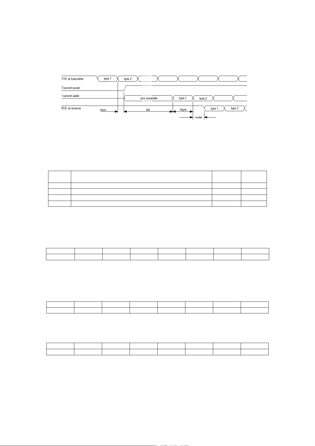
5.15.1 Receive To Transmit Switching Time
Symbol
Description
Semiduplex
Simplex
ttxon
Time from external action to commencing transmission
9ms
9ms
tlid
Duration of synchronisation transmission (lead in delay)
Table B
Table B
trbyte
Duration of 1 byte at radio signal baud rate
Table C
Table C
tmdel
Modem decode latency
Table D
Table D
Baud
150
300
600
1200
2400
4800
9600
Min tlid
80ms
60ms
40ms
40ms
40ms
20ms
30ms
Baud
150
300
600
1200
2400
4800
9600
trbyte
66.7ms
33.3ms
16.7ms
8.3ms
4.17ms
2.08ms
1.04ms
Baud
150
300
600
1200
2400
4800
9600
tmdel
6.9ms
3.5ms
1.7ms
1.3ms
1ms
1ms
1ms
When using the internal modem the action that initiates transmission can be either receipt of a
character at the serial port or the operation of RTS. These examples use the first mode. The
radio does nothing until the stop bit of the first character for transmission has been received, the
transmitter is then started:
The time delay between receipt of the stop bit for the first character to be transmitted at the
transmitting radio and output of the start bit of that character at the receiving radio is the sum of
the values ttxon, tlid, trbyte, and tmdel shown in the diagram above. Values for these
parameters are indicated below:
TABLE A: Timing values for duplex and simplex modes are as follows:
TABLE B: The lead in delay is a programmable parameter but minimum values dependant on
baud rate must be adhered to. However, in a scanning system with the base station on
continuous transmit the base station lead in delay can be set for Zero (thereby saving valuable
time) as the internal outstation modems will always be synchronised.
TABLE C: The duration of a byte at the radio baud rate is dependant upon the data format
employed, the table below assumes a format of one start bit, 8 data bits, no parity and 1 stop
bit, i.e. a total of 10 bits per character. If another format is used the appropriate correction must
be made.
TABLE D: The modem decodes latency takes into account delays introduced by hardware and
software filters. The total delay is baud rate dependant:
WSN Manual Page 21 of 34 Rev. G – 4 March 2007
Page 22
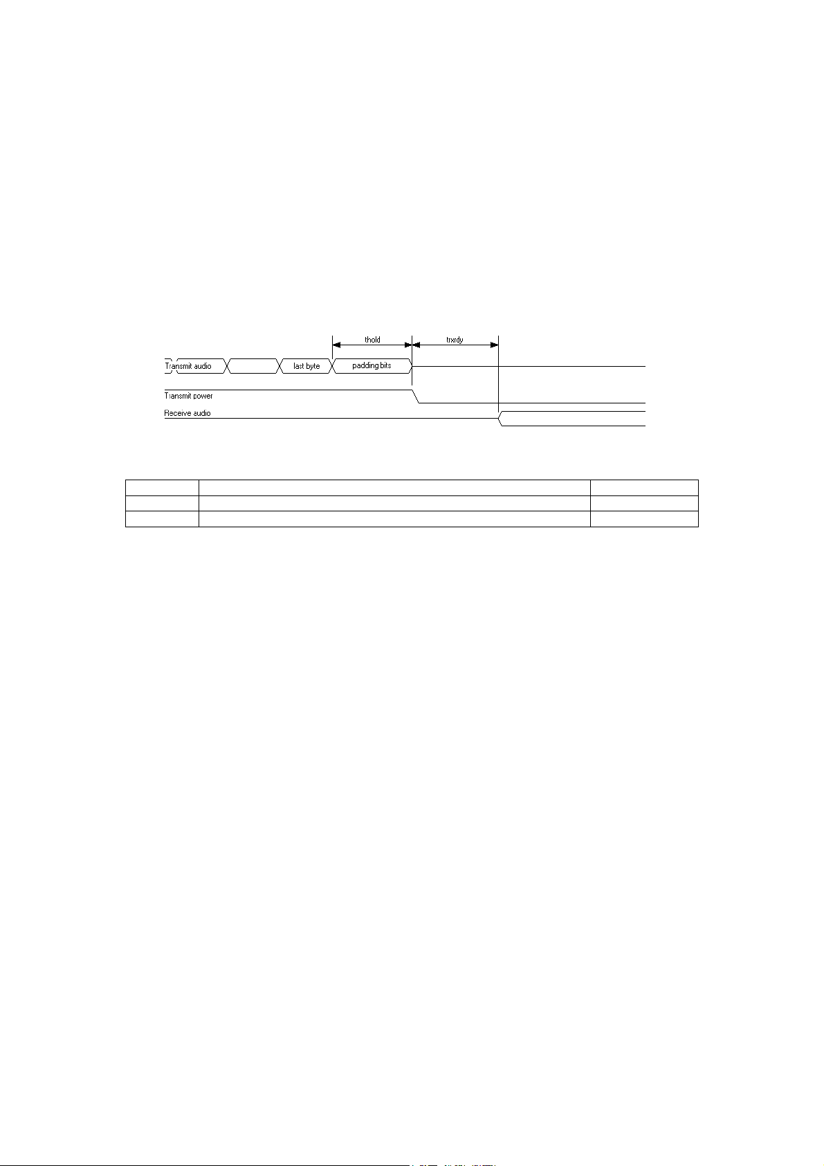
5.15.2 Message Duration
symbol
Description
value
thold
Period for which carrier is held up after sending last data byte
2.5ms + LOD
trxrdy
Time to reload transmit synthesiser in simplex mode
6ms
The time taken to transmit a message can be simply derived by multiplying the number of
characters in a message by the values given in table C making any appropriate corrections for
data format. The exception is 9600 baud where extra synchronisation sent during the message
must be taken into account, 8 synchronisation bits lasting a total of 0.833ms are sent after every
eighth message character.
5.15.3 Transmit To Receive Switching Time
In full or semi-duplex operation transmit to receive switching time does not need to be
considered as the receive path is maintained during a transmission, in simplex operation some
time must be allowed to reload the transmitter synthesiser to stop it from interfering with the
receiver. The diagram below indicates the minimum time in which the radio is able to receive a
signal after completing a transmission.
During the time thold the radio transmits some padding bits to allow for propagation delays in
the receiving device before shutting off the carrier, this prevents possible chopping of the
message tail. The time thold is composed of a fixed 2.5ms period plus the programmable value
LOD (lead out delay). LOD is normally set to zero. After the time trxrdy has expired the radio is
ready to receive a new signal.
N.B. If RTS/CTS handshaking is not used the transmitter is turned on whenever data is received
at the serial port, the transmitter is left on until all buffered data has been transmitted and no
data has been input for a time equivalent to the length of two characters at the radio baud rate
(refer to table C). In general data transmitted by the radio is delayed with respect to its receipt at
the serial port by the receive to transmit switching time, if the radio baud rate and serial port
baud rate and both data formats are the same this delay remains constant throughout the
transmission. At the higher baud rates this delay is generally greater than the length of two
characters and so the procedure to stop transmission is started as soon as the last character
has been sent, at the lower baud rates however it is possible that the time thold is extended
while the radio waits for the two character timeout to expire, this can also happen if data
characters are not loaded back to back into the serial port.
WSN Manual Page 22 of 34 Rev. G – 4 March 2007
Page 23

5.16 POWER CONSUMPTION
TX Power
5W
4W
3W
2W
1W
500mW
200mW
100mW
50mW
Max. Current
2.1A
1.8A
1.6A
1.3A
950mA
675mA
500mA
390mA
300mA
The WSN is a very low power product and is ideal for operation from batteries with solar power
backup. The information below is intended to help the user decide on the best battery and solar
cell size for operation at non-powered sites.
5.16.1 Transmitter RF power verses current
5.17 POWER SAVE MODE
The WSN is equipped with an internal and external power save mode. These are outlined
below:
5.17.1 Internal Power Save
In this mode the microprocessor switches the transceiver off and after a pre-programmed time
(Save on time) switches the unit back on (Save off time). If a carrier is not detected then the
transceiver again switches off. If during the time the transceiver is awake a carrier is received,
the unit will stay on. After the carrier drops out the receiver will stay on until the programmed
resume time elapses. Once the resume time has elapsed the unit will return to its power save
mode. The Save On/Off and Resume time are all programmable via the PC program. Obviously
the amount of power saved increases with the programmed save on/off ratio, however with
power save enabled long lead times must be programmed to wake up the unit before
communication can take place. Therefore it may not be possible to run all applications under the
power save mode due to the turn around times required by the host system. In some
circumstances it is possible to achieve power save and fast polling: If polling of all outstations is
carried out in cycles with a reasonable gap between each cycle, a long initial poll can be used to
wake up all stations, the resume timer will then restart each time an outstation is polled allowing
fast access, when the cycle is complete all stations will return to power save after the resume
time has expired.
5.17.2 External Power Save
Under this mode the on/off ratio is controlled externally via the DTR line (DTR shut down must
first be enabled using the set up program). In this mode more of the modem's circuits are
shutdown (including the microprocessor), this saves more power but care must be taken to
ensure that the modem is enabled when a transmission is to take place. Note that there is a
hardware link option to allow the serial port to shut off when DTR is not active; this allows the
radio current to be reduced to its bare minimum. In applications where DTR is not connected
this link option must of course be disabled.
5.18 “RSSI” RECEIVE SIGNAL STRENGTH INDICATION
The WSN produces an internal DC signal, which is proportional to the received signal strength.
The DC signal is passed to the internal MPU where it accurately measures its value by an
internal A-D converter. The radios are individually calibrated during production so that signal
strength can then be read in dB microvolts on a PC connected to the serial port.
WSN Manual Page 23 of 34 Rev. G – 4 March 2007
Page 24

5.19 STATUS LEDS
The WSN has a number of LEDs to enable the operator to see at a glance the status of the
product and the serial port:-
RX RF Carrier Detect/Busy
TX Transmit
SYS System
RXD Receive Data
TXD Transmit Data
5.19.1 System LED
With the Exception of the System LED the remainder are self-explanatory. The System LED
lights when the radio is being programmed and is also used as a quick check as to the status of
the unit. If any alarms are detected it will flash out an Error number.
5.19.2 Error Number
The modem reports errors in two ways, firstly the BUSY led will come on and the SYS led will
flash a number of times, the BUSY led will then go out again and if the fault persists the
procedure will be repeated. An error number can be determined by counting the number of
times the SYS led flashes while the BUSY led is on.
ERROR No FAULT
1 Position of the channel switches has changed.
2 A channel has been loaded that has no RX frequency programmed.
3 Transmission has been attempted on a channel that has no TX frequency
programmed.
4 The receiver synthesiser phase locked loop has failed to lock due to bad
channel data or programming of an out range frequency.
5 The transmitter synthesiser phase locked loop has failed to lock due to
bad channel data or programming of an out range frequency.
6 The contents of the microprocessor's EEPROM are corrupted (failed
checksum) in the general program area.
7 Internal comms with a high power amplifier have failed.
8 The contents of the microprocessor's EEPROM are corrupted (failed
checksum) in the calibration area.
9 The contents of the microprocessor's EEPROM are corrupted (failed
checksum) in the factory program area.
10 No POCSAG message stored for repeat test.
11 Rotary channel switch position overridden by software.
12 Tx power setting out of range.
13 Packet Mode cycle pointer invalid.
14 Bad routing table area EEPROM checksum.
15 I2C Bus initialisation error.
WSN Manual Page 24 of 34 Rev. G – 4 March 2007
Page 25

6 STORE & FORWARD
6.1 STORE & FORWARD BASED ON CLIENT PROTOCOL.
To conserve valuable air time and avoid the possibility of collisions due to coverage overlaps
with other repeaters transmitting at the same time, only messages that require forwarding by
specific repeaters are re-transmitted when the WSN is used in “Store & Forward” mode.
Stripping out the addresses of incoming serial messages, comparing the address with the list of
outstation addresses stored in the unit and routing the messages accordingly achieve this. This
requires knowledge of the client’s message structure and, specifically, where the address can
be found in the message.
There is normally local communication at the store and forward site, via the RS232 port.
We have written various store & forward drivers to cope with a number of client specific
message formats and are always happy to write new drivers as and when required. Further
information is available from the sales office.
6.2 MODBUS
6.2.1 Setting Up MODBUS Operation
The WSN can be programmed to transport “MODBUS ASCII” or “MODBUS RTU” format
messages in single master systems. These options are selected as the “INTERFACE
PROTOCOL” in the “EDIT MODE/INTERFACE” menu. It is not necessary for all radios to run
the same Modbus interface, “MODBUS ASCII” and “MODBUS RTU” modes can be mixed within
a system.
When Modbus modes are enabled the “NETWORK ID” and “RADIO ADDRESS” fields must be
filled out such that every radio in a system has the same network ID, but a different radio
address. Notes should be kept detailing the installation of radios and their addresses.
When transporting Modbus messages the master station radio must be programmed with a
routing table. This is accessed in the “EDIT MODEM/INTERFACE” menu by setting “ROUTING
TABLE” to “ON” and selecting “EDIT ROUTING TABLE”. This selection leads to several pages
of Modbus addresses and the route by which every Modbus address is reached must then be
entered, for example if the Modbus device with address 37 is physically connected to the radio
with radio address 23, and radio 23 is accessed from the base station via relay radios 4 and 19,
then the field entitled “MBUS 37” should be loaded with the route “4,19,23”. If the Modbus
devices with Modbus addresses 65 and 93 are physically connected to radio 45 and no relays
are required then the fields entitled “MBUS 65” and “MBUS 93” should both be loaded with “45”.
6.2.2 MODBUS Operation
Operation in Modbus modes relies on the master/slave poll/reply nature of Modbus. The set up
of the radios does not differentiate between a master and slave; the only difference in practice
would be that the master station radio will be loaded with a routing table. There is no restriction
on the number of masters in a system, but they should all be loaded with routing tables.
When a poll is initiated at a master station radio the destination Modbus address in the Modbus
message is looked up in the routing table to determine the addresses of the radio(s) required to
complete the link, the message is then sent and all the radios expect to send a reply back the
same way. Once this reply has been sent the radios are all ready to start another poll/reply
sequence.
WSN Manual Page 25 of 34 Rev. G – 4 March 2007
Page 26

If a radio is specified as a relay in a link, any locally connected Modbus devices will not be
aware of communications that take place as no activity occurs on the serial port in this state.
This may cause problems however if more than one master exists in a system as a radio that is
being used as a link in a relay is not available to transmit messages.
6.2.3 Power-Save Operation With MODBUS
When Modbus modes are enabled in the configuration programme two further fields appear
entitled “MIN PWR SAVE ADDRESS” and “MAX PWR SAVE ADDRESS”. If power save
operation is not required set both these fields to zero.
If power save operation is required it is enabled by setting the “RADIO ADDRESS” to a value
greater or equal to “MIN PWR SAVE ADDRESS” and less than or equal to “MAX PWR SAVE
ADDRESS”. The radio will then enter low power standby mode for the time programmed in the
“PSAVE ON TIME” field in the main edit menu, it will then wake up and check for an incoming
signal, if none is present it will return to sleep and repeat the cycle. If a signal is detected the
radio will stay awake until a reply to the outward-bound message has been returned.
When the master station or relay radios send an outward bound message, the address of the
radio to which the message is being sent is checked against the min and max power save
addresses, if a power saved radio is indicated a cyclic wake up message is sent for the period
indicated by the programmed power save on time before the actual data message is sent, if a
power saved radio is not indicated the data message is sent immediately. These parameters
along with some others are also used to calculate a timeout time in the event that no reply is
received. It is therefore essential that all radios in a system are programmed with the same
parameters even if not power saved, otherwise communications will fail.
Note that if “DTR SHUTDOWN” is enabled a radio remains completely shut down while DTR is
inactive, it will not wake up according to the power save timer to see if any incoming messages
are present. This mode should therefore only be used in conjunction with real time message
scheduling.
6.2.4 Serial Port Handshaking With MODBUS
When Modbus modes are enabled the DTR and DSR signalling lines can be used to assist in
power saving the host Modbus device. The RTS and CTS lines are not used and the “RTS/CTS
HANDSHAKE” option in the “EDIT MODEM/INTERFACE” menu of the WinA4P programme
should be set to “OFF” in RS232 versions. When the Modbus slave is ready to accept data it
should assert DTR, DSR will be asserted in response and the received message will be output
to the Modbus device. The “HOST INACTIVITY TIME” field in the set up programme defines a
time limit for the Modbus device to assert DTR in response an incoming message and if this
time limit is exceeded the radio sends back a reply indicating the destination device failed to
respond and the link is cancelled. After sending a response, the Modbus slave may then
release DTR and return to power save mode. Note that as long as DTR is asserted the radio will
not return to its power save mode (if enabled in the setup programme). DSR will remain
asserted in this case.
The master station can also control the power saving of its radio using DTR, the radio will
operate in power save mode as long as DTR is not active, asserting DTR wakes the radio,
DSR is asserted in return to indicate that the radio is awake and ready to accept data.
If use of the handshake lines is not required DTR should be connected to a voltage of +3.5 to
+15V such that sleep mode is never allowed.
WSN Manual Page 26 of 34 Rev. G – 4 March 2007
Page 27

6.2.5 Timeouts in MODBUS Modes
When a transmission from a master station radio is made in Modbus mode the radio will
calculate a timeout for a reply, this calculation is based on many configuration parameters
including the radio baud rate, lead in delay, host inactivity time, maximum message length,
power save timing etc. If power saving is enabled and the baud rate is low this time can be large
(the calculation limits the result to a maximum of 4.25 minutes. To reduce the possibility of
“hung” radios the destination radio will send a link-closing message if the destination Modbus
slave does not reply. This link-closing message is only used by the radios to close the link, it is
not passed to the Modbus master.
If the Modbus master itself times out before the radio link does, it can send another poll, and
radios along the link will cancel the previous route and set up the new one. The exception to this
is the previous destination radio if it is still trying to wake up its Modbus slave, it will ignore the
new message and try to download its original message when the slave awakes, a conflict will
then arise if a reply is sent. To avoid this situation the Modbus master timeout time should allow
the maximum “HOST INACTIVITY TIME” to expire plus the time required to get a message and
its reply through the link.
6.3 RFT ROUTING PROTOCOL
6.3.1 Setting Up RFT Routing Operation
The WSN can be programmed to route non-specific protocol messages in single master
systems using “RFT ROUTING” mode. This mode supports relay messaging. This option is
selected as the “INTERFACE PROTOCOL” in the “EDIT MODEM/INTERFACE” menu.
In describing operation the address contained in the host system message will be referred to as
the “protocol address” and address programmed in the radio under the “RADIO ADDRESS”
field in the setup program will be referred to as the “radio address”.
RFT Routing mode is controlled at the master station by picking out an 8 bit protocol address
field in the message to be sent, this address is then looked up in the routing table stored in the
master station radio. The routing table can contain the radio address (as programmed in the
RADIO ADDRESS field in the setup program) of a single radio connected to the required
destination device or a list of relay radio addresses plus the destination radio address. The
message is then transmitted from the base station radio as a packet with the routing information
prefixed to it. The message is then relayed through any relay radios specified until it reaches the
destination radio where it is output from the serial port in its original form with the packet
information removed. During this process each radio considers itself to be part of an established
link. A reply is then expected, however the outstation radios are not programmed with routing
tables, a reply issued is assumed to be destined to the master station. The address in the
protocol message is therefore not checked and the reply is simply sent back down the
established link to the master station radio where it is output from the serial port. As the reply is
passed back the link members no longer consider themselves to be part of an established link
and return to idle.
Note that there is no differentiation in operating mode between a relay radio and an outstation
radio, if an outstation radio is specified as a relay in a link any device connected to the local
serial port will be unaware of relay communications taking place.
The packet used to transfer protocol messages specifies the route to be taken and also the
current stage in the route, it is therefore of no concern if radios further down a relay link “hear”
the message before they are expected to repeat it, they will ignore the message until specifically
requested to repeat it.
WSN Manual Page 27 of 34 Rev. G – 4 March 2007
Page 28

The position of the address in the protocol field is specified using the “ADDRESS OFFSET”
parameter in the setup programme. A setting of 0 specifies zero offset, i.e. the address is the
first byte in the message, an offset of 6 specifies the 7th message byte and so on. 16 bit
addressing or more is not supported as a maximum of only 256 destinations can be supported
by the routing table. If the protocol message format does use 16 bit addressing specify the
offset for the least significant byte and try to ensure that no two devices use the same l.s.b. in
their address.
In order to determine the position of the address in a protocol message the radio has to know
where the message starts and ends, this can be done in one of two ways: If the RTS/CTS
HANDSHAKE option is turned on (option only available in RS232 Full Handshaking and 5V TTL
radio versions), RTS should be activated before commencing a message, CTS will be activated
in response and the message may be loaded. The first character received after CTS becomes
active is considered to be the start of the message. Transmission will start as soon as enough
characters have been loaded for the protocol address to be extracted and the route determined
from the routing table. Transmission continues until RTS is de-activated, CTS will drop when
transmission is complete. CTS may also drop if the serial input buffer becomes more than ¾ full
to implement flow control, if this happens RTS should be kept active until CTS is re-activated,
more characters may then be loaded or RTS may be dropped.
If the RTS/CTS HANDSHAKE option is turned off or is not an available option, the radio relies
on gaps in the serial data to determine the start and end of messages. A gap equivalent to two
character periods at the serial port baud rate is treated as a message end. The first character
received after such a gap is treated as the first character of the next message.
When RFT ROUTING mode is enabled the “NETWORK ID” and “RADIO ADDRESS” fields
must be filled out such that every radio in a system has the same network id, but a different
radio address. Notes should be kept detailing the installation of radios and their addresses.
The master station radio must be programmed with a routing table; this is accessed in the “EDIT
MODEM/INTERFACE” menu by setting “ROUTING TABLE” to “ON” and selecting “EDIT
ROUTING TABLE”. This selection leads to several pages of protocol addresses, the route by
which every protocol address is reached must then be entered, for example if the device with
protocol address 37 is physically connected to the radio with radio address 23, and radio 23 is
accessed from the base station via relay radios 4 and 19, then the field entitled “ADDR 37”
should be loaded with the route “4,19,23”. If the devices with protocol addresses 65 and 93 are
physically connected to radio 45 and no relays are required then the fields entitled “ADDR 65”
and “ADDR 93” should both be loaded with “45”.
6.3.2 Power-Save Operation With RFT Routing
When RFT ROUTING mode is enabled in the configuration programme two further fields appear
entitled “MIN PWR SAVE ADDRESS” and “MAX PWR SAVE ADDRESS”, if power save
operation is not required set both these fields to zero.
If power save operation is required it is enabled by setting the “RADIO ADDRESS” to a value
greater or equal to “MIN PWR SAVE ADDRESS” and less than or equal to “MAX PWR SAVE
ADDRESS”. The radio will then enter low power standby mode for the time programmed in the
“PSAVE ON TIME” field in the main edit menu, it will then wake up and check for an incoming
signal, if none is present it will return to sleep and repeat the cycle. If a signal is detected the
radio will stay awake until a reply to the outward-bound message has been returned.
When the master station or relay radios send an outward bound message, the address of the
radio to which the message is being sent is checked against the min and max power save
addresses, if a power saved radio is indicated a cyclic wake up message is sent for the period
indicated by the programmed power save on time before the actual data message is sent, if a
power saved radio is not indicated the data message is sent immediately. These parameters
along with some others are also used to calculate a timeout time in the event that no reply is
received. It is therefore essential that all radios in a system are programmed with the same
parameters even if not power saved, otherwise communications will fail.
Note that if “DTR SHUTDOWN” is enabled a radio remains completely shut down while DTR is
inactive, it will not wake up according to the power save timer to see if any incoming messages
are present. This mode should therefore only be used in conjunction with real time message
scheduling.
WSN Manual Page 28 of 34 Rev. G – 4 March 2007
Page 29

6.3.3 Serial Port Handshaking With RFT Routing
When RFT ROUTING mode is enabled the RS232 port lines DTR and DSR, can be used to
assist in power saving. The RTS and CTS lines are optionally used according to the “RTS/CTS
HANDSHAKE” option in the “EDIT MODEM/INTERFACE” menu for flow control. When the
slave is ready to accept data it should assert DTR, DSR will be asserted in response and the
received message will be output to the device. The “HOST INACTIVITY TIME” field in the set up
programme defines a time limit for the device to assert DTR. If this time limit is exceeded the
radio sends back a reply indicating the destination device failed to respond and the link is
cancelled (this message is not output to the device connected to the master station serial port).
After sending a response, the slave may then release DTR and return to power save mode.
Note that as long as DTR is asserted the radio will not return to its power save mode (if enabled
in the setup programme). DSR will remain asserted in this case.
The master station can also control the power saving of its radio using DTR, the radio will
operate in power save mode as long as DTR is not active, asserting DTR wakes the radio, DSR
is asserted in return to indicate that the radio is awake and ready to accept data.
If use of the handshake lines is not required DTR should be connected either to a voltage of
+3.5 to +15V such that sleep mode is never allowed.
6.3.4 Timeouts in RFT Routing Mode
When a transmission from a master station radio is made in RFT ROUTING mode the radio will
calculate a timeout for a reply, this calculation is based on many configuration parameters
including the radio baud rate, lead in delay, host inactivity time, maximum message length,
power save timing etc. If power saving is enabled and the baud rate is low this time can be large
(the calculation limits the result to a maximum of 4.25 minutes. To reduce the possibility of
“hung” radios the destination radio will send a link-closing message if the destination slave does
not reply. This link-closing message is only used by the radios to close the link, it is not passed
to the device connected to the master station radio.
If the device connected to the master station radio itself times out before the radio link does, it
can send another poll, radios along the link will cancel the previous route and set up the new
one. The exception to this is the previous destination radio if it is still trying to wake up its slave,
it will ignore the new message and try to download its original message when the slave awakes,
a conflict will then arise if a reply is sent. To avoid this situation the master timeout time should
allow the maximum “HOST INACTIVITY TIME” to expire plus the time required to get a
message and its reply through the link.
WSN Manual Page 29 of 34 Rev. G – 4 March 2007
Page 30

7 INSTALLATION
7.1 INTRODUCTION
Correct installation of the WSN radios should ensure reliable data communications for many
years. The most important installation points to remember are:-
Suitable antenna system mounted at the correct height & polarisation to achieve the required
distance.
Reliable power supply capable of supplying the correct voltage and current.
Correct installation for the environment.
Correct interface and set-up.
Assuming the unit has been correctly installed and tested at the correct data speed, other
factors that may affect the performance include the RF power (normally specified by the
regulating authority), the local topography and the weather.
7.2 POWER SUPPLIES
The WSN can be powered from any power source provided that the voltage is between 9.6VDC
& 16VDC with a –ve GND. If a +ve GND system is in use, an isolated converter will be
required.
The WSN requires a supply capable of providing between 300mA and 2.5A depending on the
maximum transmit power required.
Under no circumstances should the output of the supply rise above 16VDC.
For 240/110VAC, 50VDC or 24VDC, a range of uninterruptible power supply units are available
with a in-built charger and power fail indication. A range of suitable Gel type batteries is
available should a back-up supply be required during power failures.
7.3 EFFECTIVE RADIATED POWER (ERP)
The Radio Frequency (RF) Power allowed can be specified in two ways:
The “Terminated power into 50 ohms”, which in the case of the WSN would be a
maximum of 5W.
The “ERP”, which is the actual radiated power, taking into account the gain/loss of
the antenna and loss in the feeder. Hence, if we use an aerial with a gain of 3dB (x2)
and assume no loss in the cable, the ERP with an input of 5W would be 10W.
The gain of an antenna is very useful as it enables lower power transmitters to be used in many
cases in place of high power transmitters, with the advantage of a much lower current
consumption.
For example if the ERP allowed for a link is 5W, then a WSN operating at 5W into a unity gain
antenna, would require a supply current of 2.1Amps to provide an ERP of 5W.
If however, we use an 8 element directional Yagi with a Gain of 10dB, we would only need
500mW of RF Power for the same performance.
With a WSN operating at 500mW, the current consumption would only be 600mA. If the site is
battery or solar powered then the saving is very significant.
Care must be taken when setting the power within a MPT1329/1411 system, as permitted RF
power is specified as a maximum ERP.
WSN Manual Page 30 of 34 Rev. G – 4 March 2007
Page 31
7.4 ANTENNAS, COAX FEEDERS & PERIPHERALS
Antenna Types
Typical
Gain
Polarisation
Use
Vertical Whip
0dB
Vertical
In-house testing and local use
Helical
- 3dB
Vertical
End Fed Dipole
0dB
Vertical
Local Scanner or Multi-point system
Folded Dipole
0dB
Vertical/Horizontal
6dB Co-linear
+6dB
Vertical
Wide area Scanner
3dB Co-linear
+3dB
Vertical
12 Element Yagi
+12dB
Vertical/Horizontal
Outstation or point to point link
4 Element Yagi
+8dB
Vertical/Horizontal
Corner Reflector
+10dB
Vertical/Horizontal
Outstations in areas of bad
Interference or where radiation must
be kept to a minimum
Patch Antenna
0dB
Vertical/Horizontal
Kiosk or Wall mounting
7.4.1 Antennas
Apart from the radio modem, the antenna is probably the most important part of the system. The
wrong choice or a bad installation will almost certainly impede the product’s performance.
Depending on the application either an omni-directional or directional antenna will be required.
7.4.2 Types of Antennas
We can offer a complete range of antennas to suit all applications; details of some of the more
popular ones are outlined below:-
7.4.3 Directional Antennas
For point-to-point communications, a directional Yagi or corner reflector is probably the best
type of antenna to use, as directional antennas provide relatively high gain in the forward
direction within a limited beamwidth and very good rejection of unwanted signals at the rear.
The number of elements and hence the size, will depend on the gain and beam width required.
Yagi antennas can be used in the vertically polarised or horizontally polarised, but
communicating products should be fitted with antennas of the same polarisation. If not a loss of
signal strength will occur. Use of both vertical and horizontal propagation can be very useful on
single or repeater sites where isolation is required between communication paths. Using
differently polarised antennas for each path will increase the isolation, which will reduce
possible interference between the paths.
7.4.4 Omni-Directional Antennas
With approximately 360-degree radiation pattern, this type of antenna is ideal for the central site
of a scanning station or where communication to a group of widely dispersed outstations is
required.
7.4.5 Patch or Plate Antennas
The patch or plate antennas are normally rectangular or round, with a back plate of aluminium
or stainless steel. A polycarbonate or ABS cover is fitted to protect the antenna from the
environment. This type of antenna can be produced in different sizes with various radiation
patterns to suit the application. Depending on the construction and radiation pattern, the gain is
usually between -3dB to + 3dB. Their use is very popular on roadside kiosks, buses, trains,
aircraft, or where covert communication is required.
WSN Manual Page 31 of 34 Rev. G – 4 March 2007
Page 32

7.4.6 Antenna Mounting
Cable Type
Attenuation per 100ft
Attenuation per 100m
RG58
13.0dB
37.0dB
RG213
6.0dB
17.5dB
LDF2-50 3/8inch Foam Heliax
2.44dB
8.0dB
LDF4-50 1/2inch Foam Heliax
1.60dB
5.26dB
LDF5-50 7/8inch Foam Heliax
0.883dB
2.9dB
LDF6-50 1-1/4inch Foam Heliax
0.654dB
2.15dB
LDF7-50 1-5/8inch Foam Heliax
0.547dB
1.79dB
Location: The antenna should be mounted in a clear area, as far away as possible from
obstructions such as metal constructions, buildings and foliage.
Height: The WSN operates in the UHF band, which requires near line of sight
communication. Hence, for extended ranges the height of the antenna is
important.
7.4.7 Polarisation
A Yagi or corner reflector antenna can be mounted for vertical or horizontal polarisation.
Scanning systems employing a vertically polarised antenna will necessitate the outstation
antennas to be of the same orientation. In vertical polarisation the elements are perpendicular to
the ground. By mixing polarisation within systems, unwanted signals can be reduced by as
much as 18dB. However, such systems require detailed planning.
7.4.8 Alignment
If a directional antenna is to be used, it will need alignment with the scanner or communicating
station. A map and compass can be used, but the final adjustment should be performed by
measuring the receive signal strength (RSSI) from the scanner, as outlined in the operations
section.
7.4.9 Antenna Coax Feeder:
As with the antenna, the use of the wrong coax feeder can seriously affect the performance of
the system. Hence, the coax cable should be selected to give a low loss over the distance
required. For outstations in the local vicinity of the scanner/ base station, the loss is not very
important but for distant stations the loss is very important. As a rule of thumb, never operate a
system with a loss of more than 3dB.
To illustrate the point, a 3dB loss in the feeder will result in a 50% loss in transmitted RF power
and a 50% reduction in the received signal strength. Therefore, double the received signal
strength will be required for the same bit error rate. Although increasing the RF power will
compensate for the loss in transmitted power, there is no effective way to improve the received
signal strength.
Coax cable should be installed in accordance with the manufacturers’ instructions, with cable
runs kept as short as possible. Sharp bends, kinks and cable strain must be avoided at all
costs. If long term reliability is required, the cable must be securely mounted to avoid excessive
movement and longitudinal strain, due to high winds, rain and snow.
7.4.10 Signal Loss v. Cable Length at 500MHz
WSN Manual Page 32 of 34 Rev. G – 4 March 2007
Page 33
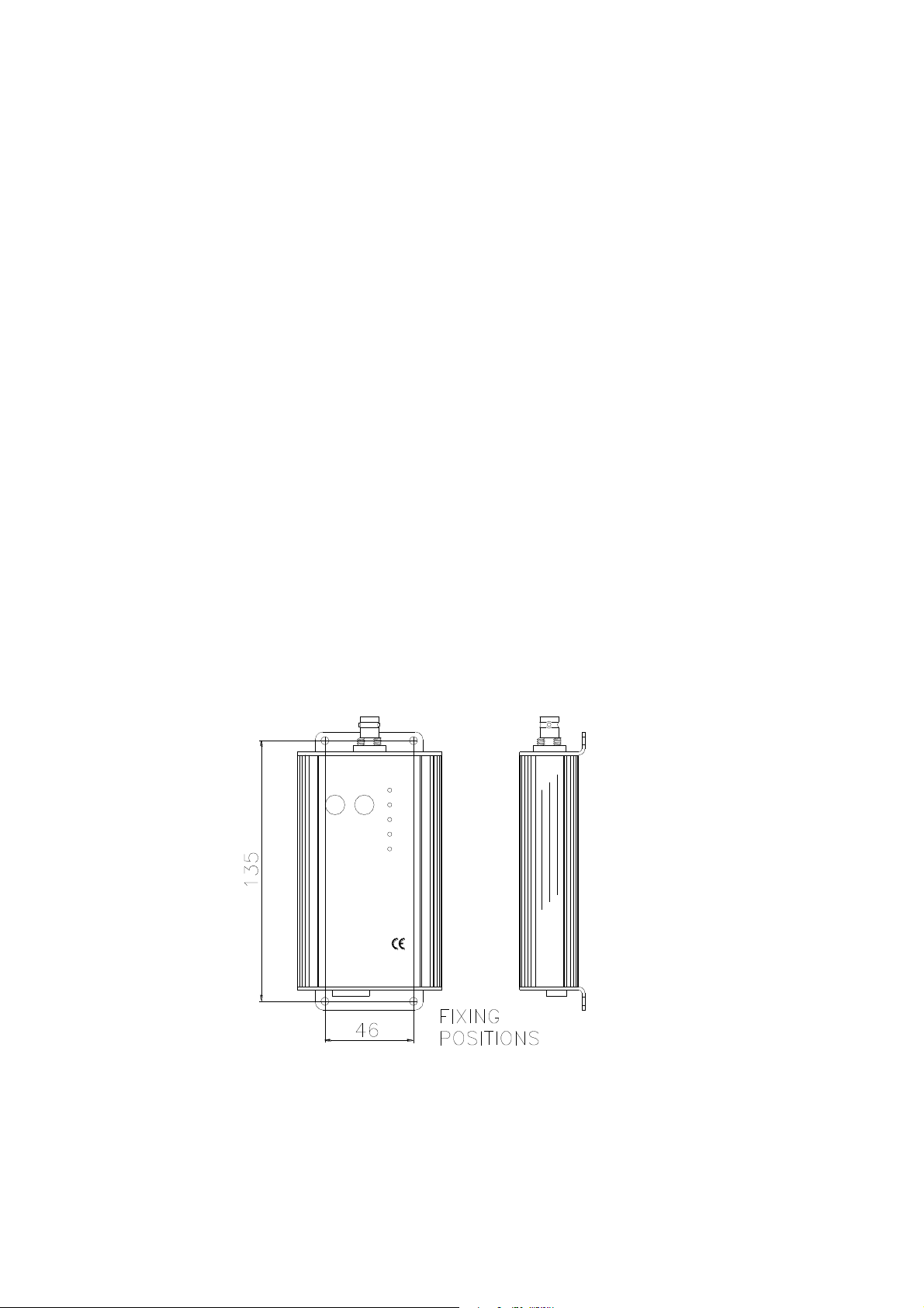
7.4.11 Coax & Connectors:
ANTENNA
BUSY
SYS
TX
Prog/Channel
Switch
TXD
RXD
INPUT
-12V+
50 Ohm coax connectors of a good quality should be used, termination must be in accordance
with the manufacturer's specification, any special tools required to terminate the connectors
must be used. Connectors exposed to the environment should be sealed to prevent the ingress
of moisture. If the cable is penetrated by water a high loss will occur and the cable will need to
be replaced. Once assembled it is advisable to test the cable and connectors for open and short
circuits.
7.4.12 VSWR Measurement:
Voltage standing wave ratio (VSWR) is the ratio of detected volts from the forward RF power, to
the detected volts from the reflected (returned) RF power. This ratio is used to measure the
combined coax cable and antenna match. A good match will ensure that most of the RF Power
is radiated, whereas a bad match will result in the reflection of a large amount of the power,
thereby reducing the transmitter's range. A perfect match will give a 1:1 ratio and bad match will
give 2:1 or higher. For guidance, a good system will measure between 1.2:1 and 1.5:1.
7.4.13 Lightning Arresters
At high or exposed sites, the use of a lightning arrester is recommended. This in-line device fits
between the antenna and the product with an earth strap connected to ground. Should a
lightning strike occur, most of the energy should be diverted to ground leaving the equipment
with little or no damage.
7.5 MOUNTING & INSTALLATION
The WSN is built into tough durable aluminium enclosure that can be mounted in any plane, but
should not be exposed to rain etc. as the enclosure and connectors do not meet the relevant IP
ratings.
If IP65, 67 or 68 is required then an additional enclosure will be required. A number of suitable
enclosures are available as options.
7.6 FIXING DETAILS
WSN Manual Page 33 of 34 Rev. G – 4 March 2007
Page 34

FF-Automation Oy
Eräkuja 2, 01600 Vantaa, FINLAND,
http://www.ff-automation.com,
email: [email protected]
Tel: +358 10 2190 500
WSN Manual Page 34 of 34 Rev. G – 4 March 2007
 Loading...