

Page 1
www.fif.com.pl
F&F Filipowski sp.j.
ul. Konstantynowska 79/81
95-200 Pabianice
Tel./fax (42) 215 23 83, 227 09 71
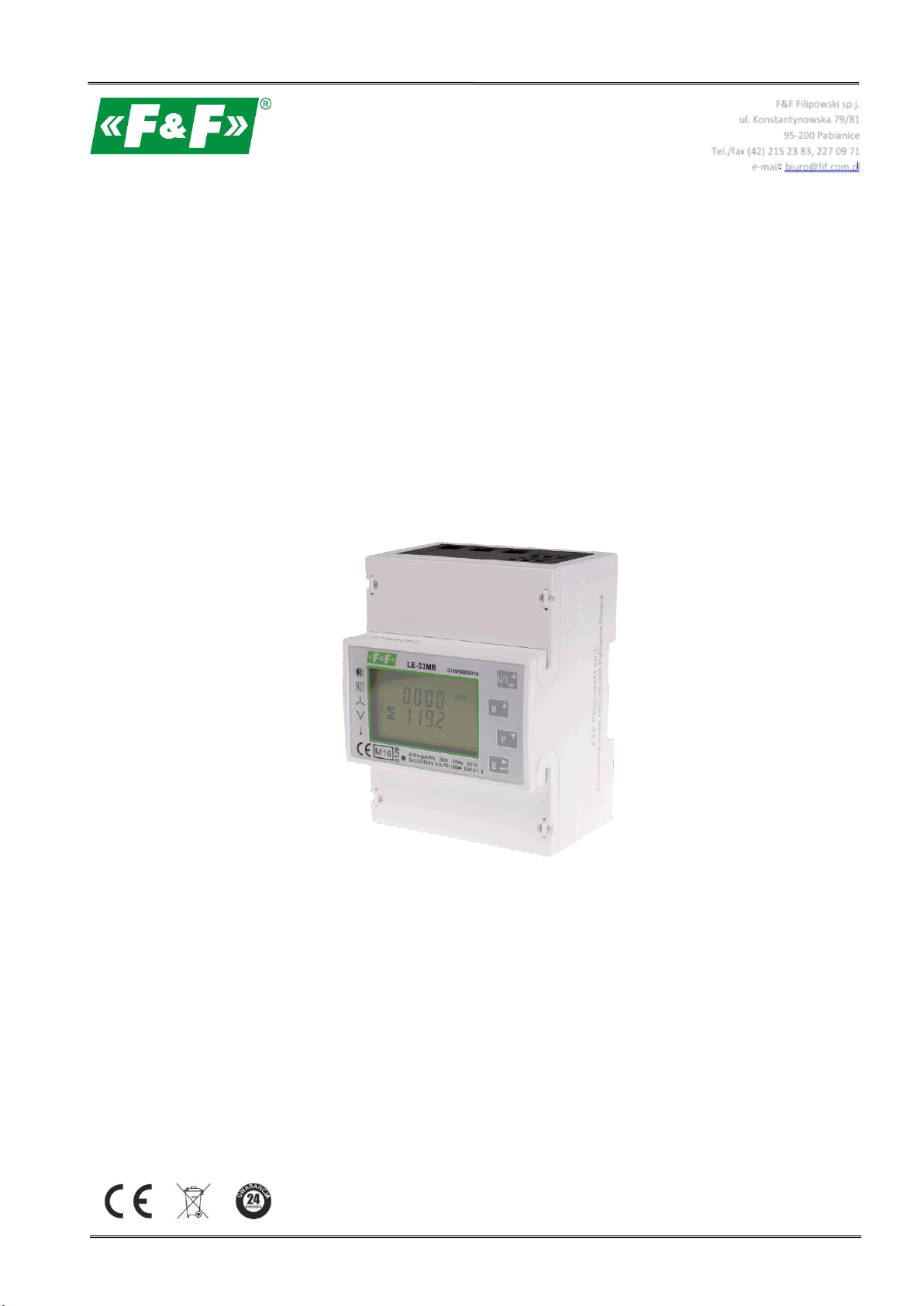
LE-03MB
Electric energy meter
1-phase / 3-phase
Bidirectional with network parameters analysis
User manual
v. 4.4 (170203)
Page 2

LE-03MB - User manual
CONTENTS
1. PURPOSE ................................................................................................................................................ 5
2. UNIT CHARACTERISTICS ......................................................................................................................... 5
2.1. Measured value ...................................................................................................................................................... 5
2.2. M-Bus protocole and communication port ............................................................................................................. 5
2.3. Pulse output ........................................................................................................................................................... 5
3. START-UP SCREENS ................................................................................................................................ 5
4. OPERATOR PANEL .................................................................................................................................. 6
4.1. Voltage and current, harmonic ............................................................................................................................... 7
4.2. Frequency, power factor and demand .................................................................................................................... 7
4.3. Power ..................................................................................................................................................................... 8
4.4. Energy measurements ............................................................................................................................................ 9
5. SETUP .................................................................................................................................................. 10
5.1.Setup entry methods .............................................................................................................................................. 10
5.1.1. Navigation ................................................................................................................................................................ 10
5.1.2. Number entry procedure ......................................................................................................................................... 10
5.2. Setup parameters .................................................................................................................................................. 11
5.2.1. Entry into configuration menu ................................................................................................................................ 11
5.2.2. M-Bus communication ............................................................................................................................................ 11
5.2.2.1. (Slave ID) Address ............................................................................................................................................ 11
5.2.2.2. Baud rate ......................................................................................................................................................... 13
5.2.2.3. Parity ................................................................................................................................................................ 13
5.2.2.4. Stop bits ........................................................................................................................................................... 14
5.2.3. Pulse output ............................................................................................................................................................ 15
5.2.3.1. Energy setup .................................................................................................................................................... 15
5.2.3.2. Pulse rate ......................................................................................................................................................... 15
5.2.3.3. Pulse duration .................................................................................................................................................. 16
5.2.4. DIT - Demand Integration Time ............................................................................................................................... 16
5.2.5. Backlit setup ............................................................................................................................................................ 17
5.2.6. Measuring system ................................................................................................................................................... 18
5.2.7. CLR ........................................................................................................................................................................... 19
5.2.8. Change password..................................................................................................................................................... 19
6. TECHNICAL SPECIFICATION .................................................................................................................. 20
6.1. Measured parameters ........................................................................................................................................... 20
6.1.1. Voltages and currents .............................................................................................................................................. 20
6.1.2. Power factor, frequency and maximum demand .................................................................................................... 21
6.1.3. Energy measurements ............................................................................................................................................. 21
2
Page 3

LE-03MB - User manual
6.2. Terminal ................................................................................................................................................................ 21
6.3. Accuracy ................................................................................................................................................................ 21
6.4. Power supply and power meter ............................................................................................................................ 22
6.5. Measurement inputs ............................................................................................................................................. 22
6.6. Pulse outputs ........................................................................................................................................................ 22
6.7. M-Bus output ........................................................................................................................................................ 22
6.8. Reference conditions of influence quantities ........................................................................................................ 22
6.9. Environment ......................................................................................................................................................... 23
6.10. Structure ............................................................................................................................................................. 23
6.11. Compliance and sealing ....................................................................................................................................... 23
7. DIMENSIONS ........................................................................................................................................ 24
8. WIRING DIAGRAM ................................................................................................................................ 24
9. M-BUS PROTOCOLE .............................................................................................................................. 25
9.1. Initialization Slave ................................................................................................................................................. 25
9.1.1. How to initialize a meter which you don’t know the address.................................................................................. 26
9.1.2. Remove the secondary address matching symbol of all the meters on Bus ........................................................... 26
9.1.3. How to initialize all meters on the bus line by using FF as broadcast address ........................................................ 26
9.1.4. How to initialize a Slave with specific address ......................................................................................................... 26
9.2. How to set baud rate............................................................................................................................................. 26
9.2.1. Point to point baud-rate setting command format (Control frame) ....................................................................... 26
9.2.2. How to use broadcast command to set baud rate................................................................................................... 27
9.3. How to set primary address .................................................................................................................................. 27
9.3.1. How to set the address of a Slave to 01 ................................................................................................................... 27
9.3.2. How to use broadcast command to set primary address to 01 ............................................................................... 27
9.3.3. How to change address from 01 to 02 ..................................................................................................................... 28
9.3.4. How to set primary address to 01 by using secondary address ............................................................................... 28
9.4. Set the complete identification of the Slave .......................................................................................................... 28
9.5. How to read out of energy information ................................................................................................................. 29
9.5.1. Use primary address 01 to read energy information ............................................................................................... 29
9.5.2. How to read out a meter’s energy information by using broadcast address 254 (FE) ............................................ 29
9.5.3. How to read out the meter’s energy information by using secondary addres ........................................................ 29
9.6. Read out of instantaneous electrical information ................................................................................................. 32
9.6.1. How to read instantaneous electrical information by using primary address ......................................................... 32
9.6.2. How to use secondary address to read out the instantaneous electrical information ............................................ 32
9.7. How to read password .......................................................................................................................................... 37
9.7.1. Change to a new password ...................................................................................................................................... 37
3
Page 4

LE-03MB - User manual
9.8. How to reset all resettable energy data ................................................................................................................. 37
9.9. Set demand interval, slide time, display time, LED time ........................................................................................ 37
9.10. Read demand interval,slide time, display time, LED time .................................................................................... 38
9.11. Read the measurement mode ............................................................................................................................. 39
9.12. Set up the measurement mode ........................................................................................................................... 39
9.13. Read the output mode of pulse 1 ........................................................................................................................ 39
9.14. Set up the output mode of pulse 1 ...................................................................................................................... 40
9.15. Read the constant of pulse 1 ............................................................................................................................... 40
9.16. Set up the constant of pulse 1 ............................................................................................................................. 40
10. MANUFACTURER'S WARRANTY .......................................................................................................... 41
4
Page 5

The first screen lights up all display
segments and can be used as a display
check.
LE-03MB - User manual
1. Purpose
LE-03MB is a static (electronic), calibrated electricity meter of single-phase and three-phase alternating
current in direct system. It is used for reading and recording of imported electricity and parameters of
the power supply with the ability of remote reading through a wired M-Bus network. Configuration of
the meter is done through the configuration menu accessible from the front panel and through the
communication port according to the software features of the M-Bus.
2. Unit characteristics
2.1. Measured value
The unit can measure and display:
Line voltage and THD% (total harmonic distortion) of all phases;
Line frequency;
Currents, current demands and current THD% of all phases;
Power, maximum power demand and power factor;
Active energy imported and exported;
Reactive energy imported and exported.
2.2. M-Bus protocole and communication port
Meter has a port with support for M-Bus protocol.
The M-Bus communication port allows you to combine the counters in the remote reading network.
2.3. Pulse output
The meter has two pulse outputs for mapping the counting of active and reactive energy.
Output 1 - terminals 9/10 - programmable, can be set to work for active or reactive energy and
parameters: impulsing and pulse length.
Output 2 - terminals 11/12 - for active energy, impulsing is 3200 pulse / kWh.
3. Start-up screens
5
Page 6
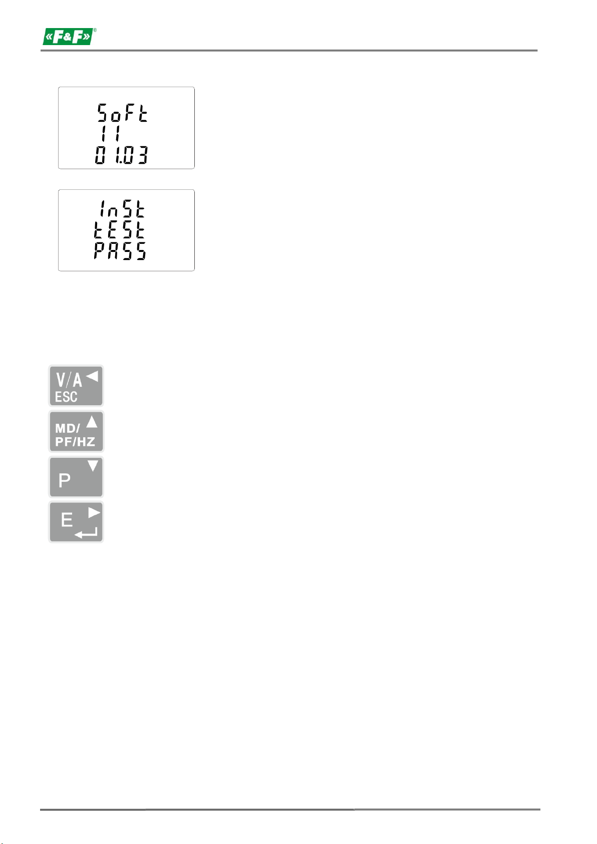
Information about software version.
The interface performs a self-test and
indicates the result if the test passes.
Select the voltage and current display
screens. In set up mode, this is the "Left" or
"Back" button.
Select the frequency and power factor
display screens. In set up mode, this is the
"Up" button.
Select the power display screens. In set up
mode, this is the "Down" button.
Select the energy display screens. In set up
mode, this is the "Enter" or "Right" button.
4. Operator panel
Buttons features:
LE-03MB - User manual
6
Page 7
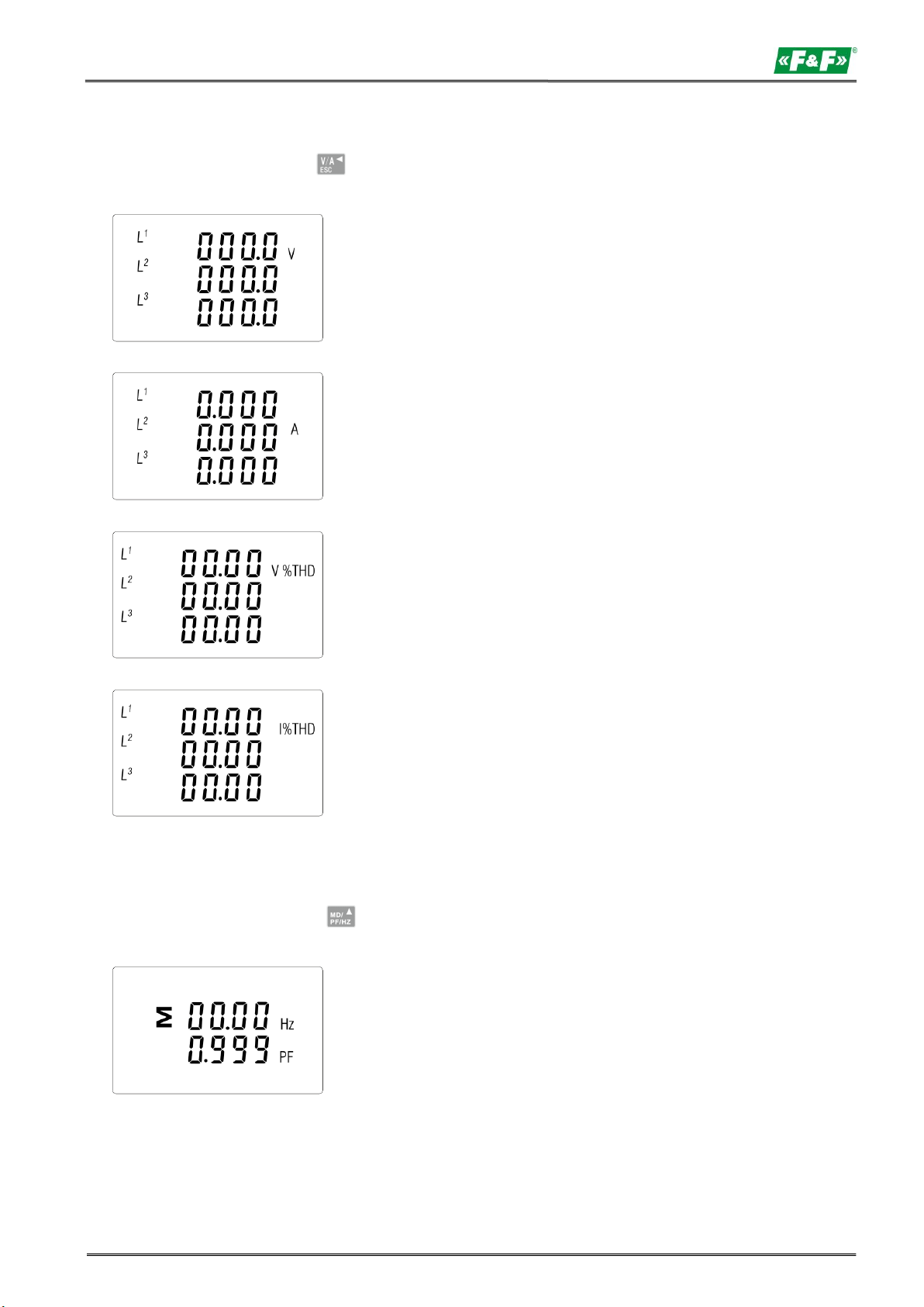
Phase to neutral voltages (3p4w)
Current on each phase
Phase to neutral voltage THD% (3p4w)
Current THD% for each phase
Frequency and power factor (total)
LE-03MB - User manual
4.1. Voltage and current, harmonic
Each successive pressing of the buton select a new range:
4.2. Frequency, power factor and demand
Each successive pressing of the button selects a new range:
7
Page 8
LE-03MB - User manual
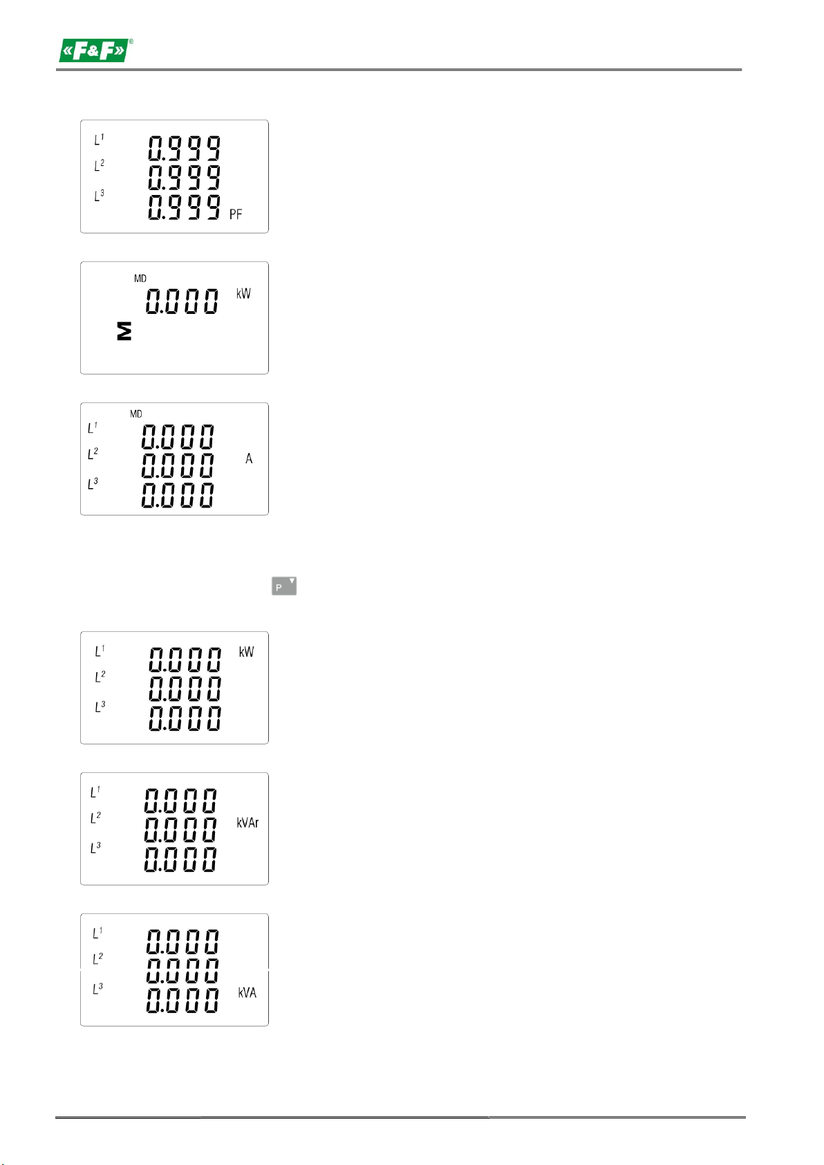
Power factor of each phase
Maximum power demand
Maximum current demand
Instantaneous active power in kW
Instantaneous reactive power in kVAr
Instantaneous Volt-amps in KVA
4.3. Power
Each successive pressing of the button select a new range:
8
Page 9
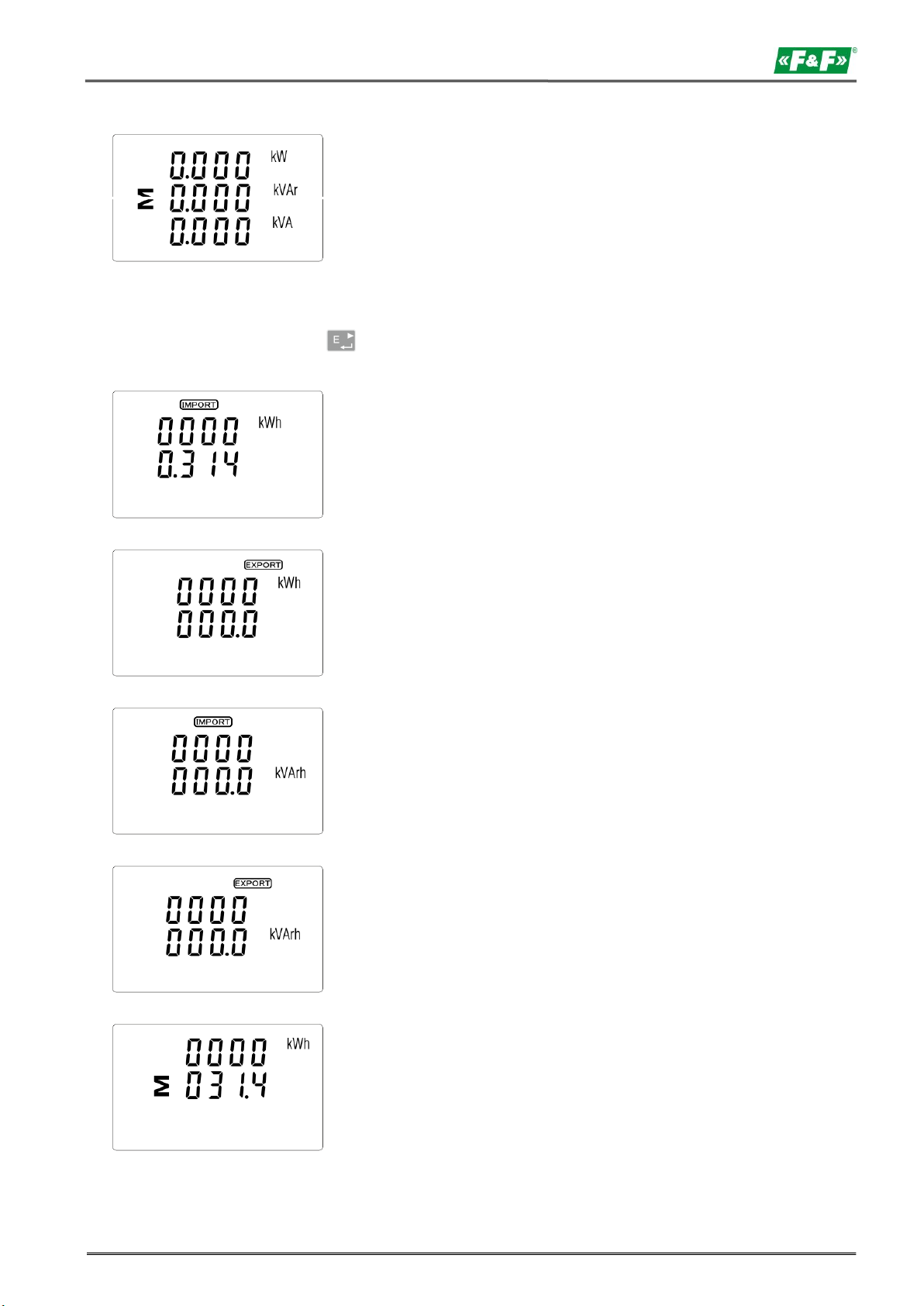
Total: kW, kvar, kVA
Imported active energy in kWh
Exported active energy in kWh
Imported reactive energy in kVArh
Exported reactive energy in kVArh
Total active energy in kWh
LE-03MB - User manual
4.4. Energy measurements
Each successive pressing of the buton select a new range:
9
Page 10

LE-03MB - User manual
Total reactive energy in kVArh
The total value of the given energy is presented in two rows.
The top row presents the higher values, the bottom row presents the lower values + fractional value.
For example:
Indications: 0027 - top row; 845.3 - bottom row presents the value of 27845.3 kWh.
5. Setup
5.1.Setup entry methods
Some menu items, such as password, require a four-digit number entry while others, such as
supply system, require selection from a number of menu options. After confirming the settings the
meter confirms the adoption of a new parameter by displaying for a moment the word "good".
5.1.1. Navigation
1. Transition to the next position configuration menu.
2. Press to confirm your selection.
3. Edition of value (change of position numer by +/-1)
4. Having selected an option from the current layer, press to confirm your selection. The SET
indicator will appear.
5. Back to the higher menu level. The SET indicator will disappear and you will be able to use the
buttons, again to select further options.
6. Exit the configuration menu to the measurements screen.
5.1.2. Number entry procedure
When setting up the unit, some screens require the entering of a nuber. In particular, on entry
to the setting up section, a password must be entered. Digits are set individually, from left to right. The
procedure is as follows:
1. The current digit to be set flashes and is set using the and buttons.
2. Press to confirm each digit setting. The SET indicator appears the last digit has been set.
3. After setting the last digit, press , to exit the numer setting routine. The SET indicator will be
removed.
10
Page 11
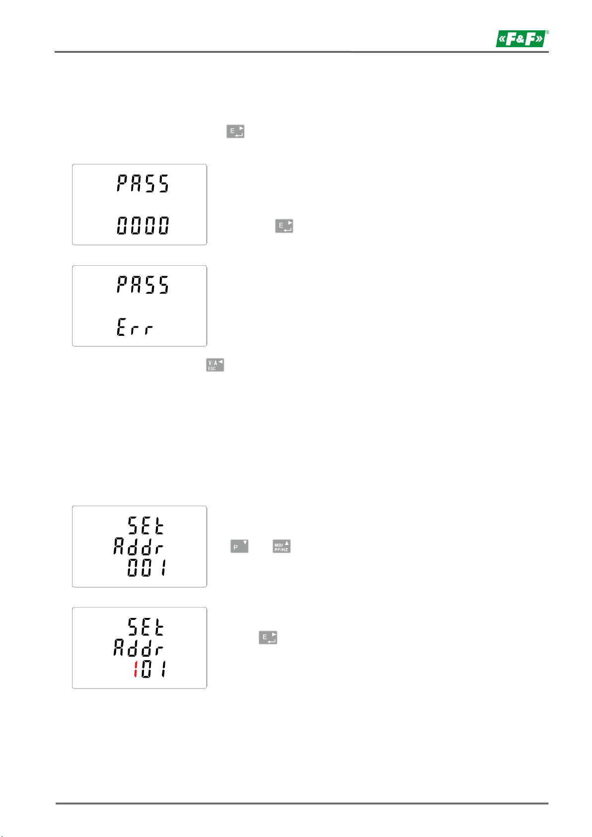
Setting up is password-protected so you must
enter the correct password (default "1000")
before processing.
Press the button for 2 seconds.
If an incorrect password is entered, the display
will show:
PASS Err
From the set up menu, use
and , buttons to select the address
ID.
Press , button to enter the selection
routine. The current setting will be flashing.
LE-03MB - User manual
5.2. Setup parameters
5.2.1. Entry into configuration menu
To enter setup mode, pressing the button for 2 seconds, until the password screen appears.
To exit setting-up mode, press repeatedly until the measurement screen is restored.
5.2.2. M-Bus communication
Setting the communication port parameters.
5.2.2.1. (Slave ID) Address
(Range 1 to 250)
11
Page 12
LE-03MB - User manual
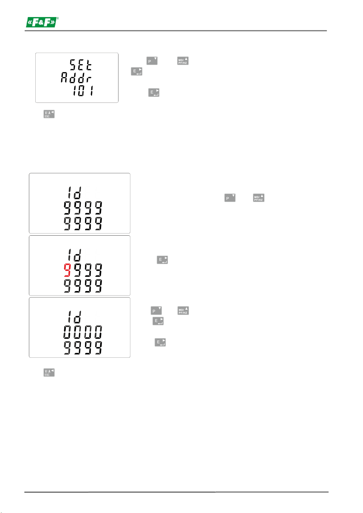
Use and to change digits and
to change position, to choose Modbus
address (001 to 250).
Press button, to confirm the selection.
From the setup menu, use and
buttons to select extended address option.
Press buton to enter the selection
routine. The current setting will be flashing.
Use and buttons to change digits
and to change position, to choose
Modbus address (00000000 to 99999999).
Press button to confirm the selection.
Press , button to return the main set up menu.
Extended address (Range 0 to 99999999).
ATTENTION!
This setting is located in the menu before the CLR feature setting.
Press , button to return the main set up menu.
12
Page 13
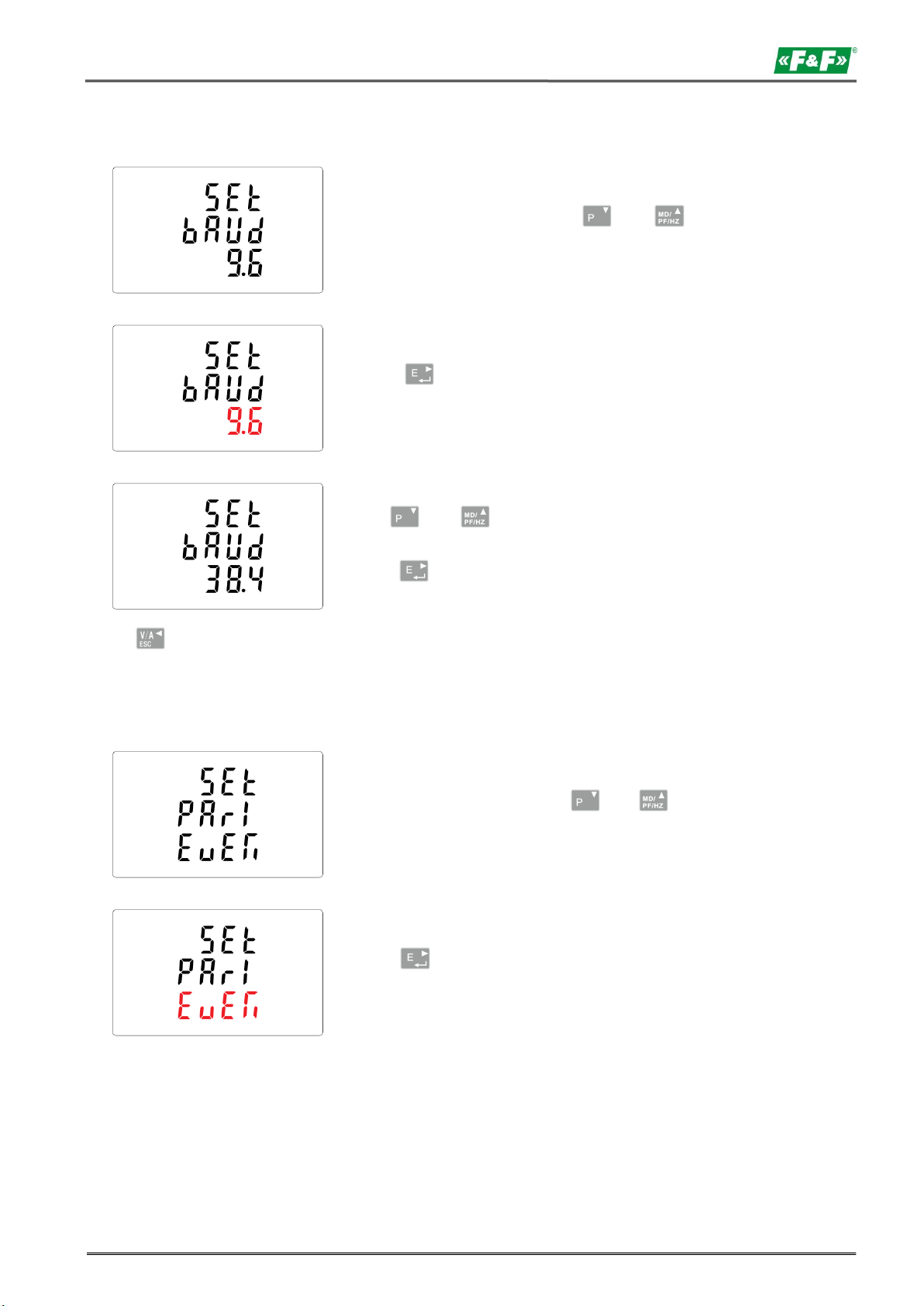
From the set up menu, use and
buttons to select the Baud rate option.
Press button to enter the selection
routine. The current setting will flash.
Use and buttons to choose Baud
rate: 0.3 / 0.6 / 1.2 / 2.4 / 4.8 / 9.6 [kbps].
Press button, to confirm the selection.
From the set up menu, use and
buttons to select the parity option.
Press to enter the selection routine.
The current setting will flash.
LE-03MB - User manual
5.2.2.2. Baud rate
Press button, to return the main set up menu.
5.2.2.3. Parity
13
Page 14
LE-03MB - User manual
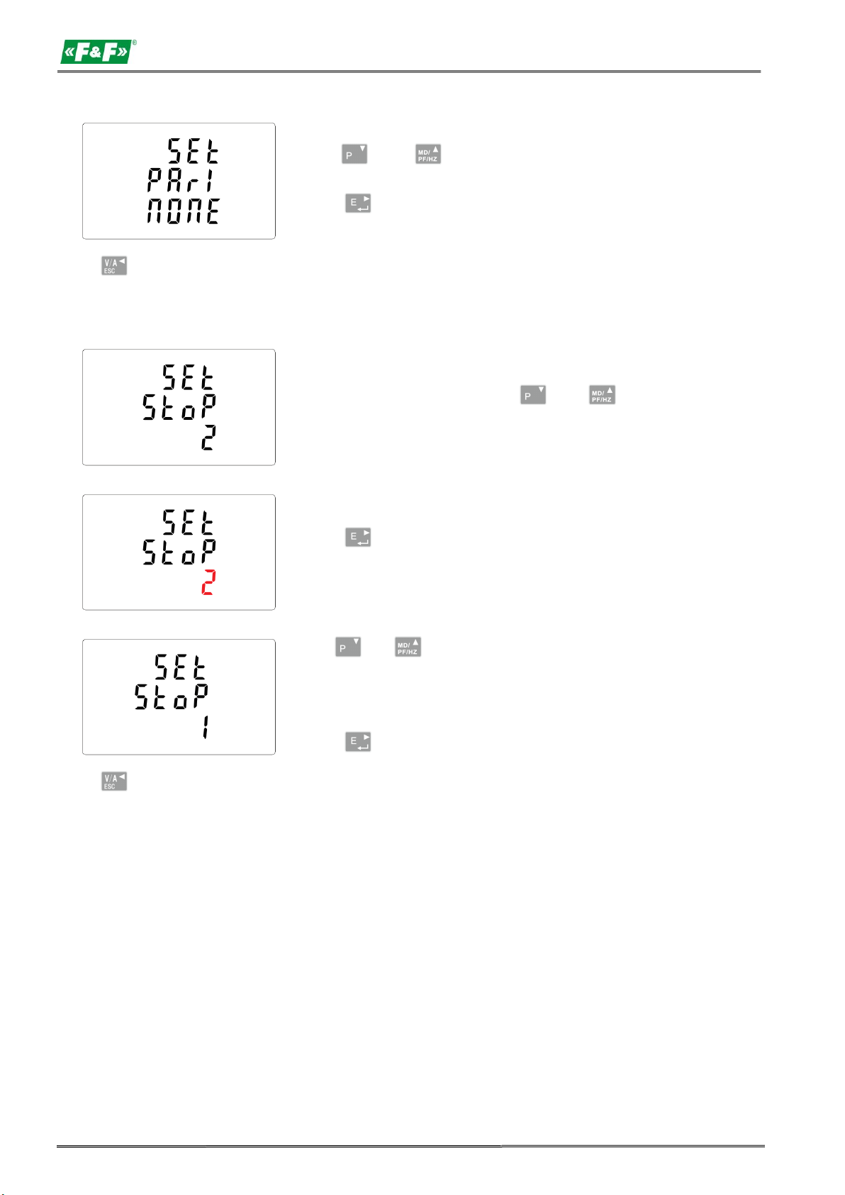
Use and buttons to choose
parity: EVEN / ODD / NONE (default).
Press buton to confirm selection.
From the set up menu, use and
buttons to select the stop bit option.
Press to enter the selection routine.
The current setting will flash.
Use and buttons to choose stop
bits: 2 or 1.
NOTE: Default value is 1. Only in case parity
set up NONE, to change stop bits to 2.
Press to confirm the selection.
Press buton to return to the main set up menu.
5.2.2.4. Stop bits
Press to return to the main set up menu.
14
Page 15
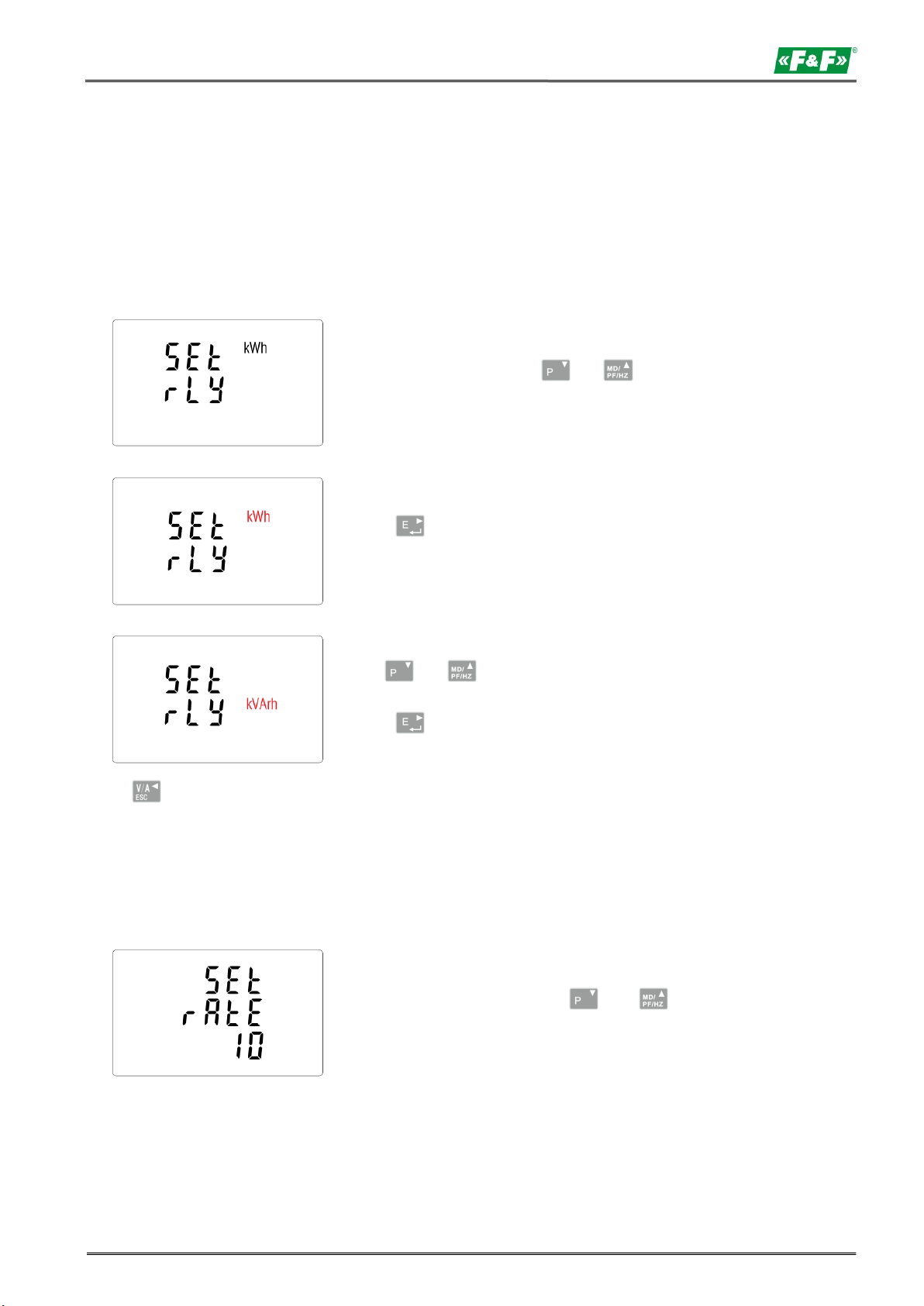
From the setup menu, use and
buttons to select the pulse output option.
Press to enter the selection routine.
The unit symbol will be flash.
Use and buttons to choose kWh or
kvarh.
Press to confirm selection.
From the setup menu, use and
buttons to select the pulse rate option.
LE-03MB - User manual
5.2.3. Pulse output
Pulse output configuration no. 1.
5.2.3.1. Energy setup
The output can be set to provide a pulse for a definied amount of Energy active (kWh) or reactive
(kvarh).
Press to return to the main set up menu.
5.2.3.2. Pulse rate
Setup value option kWh/kvarh per 1 pulse. Values: 0.01 / 0.1 / 110 / 100.
15
Page 16
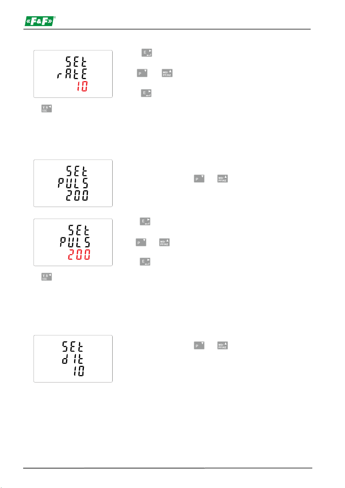
LE-03MB - User manual
Press to enter the selection routine.
The current setting will flash.
Use and buttons to select value:
0.01 /0.1 /1 /10 /100 per 1 pulse.
Press to confirm selection.
From the setup menu, use and
buttons to select the pulse width option.
Press to enter the selection routine.
The current setting will flash.
Use and buttons to choose value:
200, 100 or 60 ms.
Press to confirm the selection.
From the setup menu, use and
buttons, to select the DIT option.
The screen will show the currently
selected integration time.
Press to return to the main set up menu.
5.2.3.3. Pulse duration
Option of setting pulse length for output. Values: 200, 100 lub 60 ms.
Press to return to the main setup menu.
5.2.4. DIT - Demand Integration Time
The options are: 5, 10, 15, 30, 60 minutes.
16
Page 17
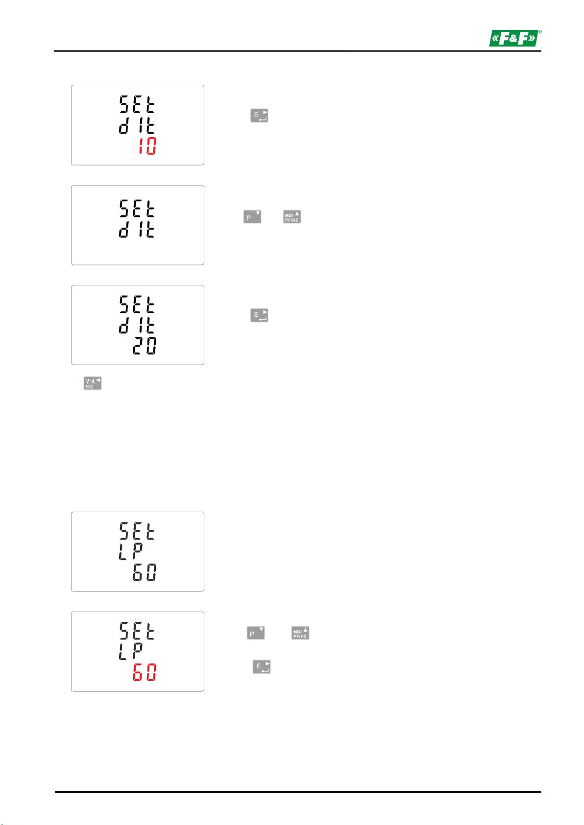
Press to enter the selection routine.
The current time interval will flash.
Use and buttons to select the
time required.
Press to confirm selection.
SET indicator will appear.
Default lasting time is 60 minutes.
if it's setted as 5, the backlit will be
off in 5 minutes from the last time
operation on the meter.
Use and buttons to select
the time.
Press to confirm the selection.
LE-03MB - User manual
Press to exit the DIT selection routine and return to the menu.
5.2.5. Backlit setup
The meter allows you to set the time of the backlight.
Time: 0 / 5 / 10 / 30 / 60 / 120 minutes.
Value 0 means that the backlight is always on.
17
Page 18
LE-03MB - User manual
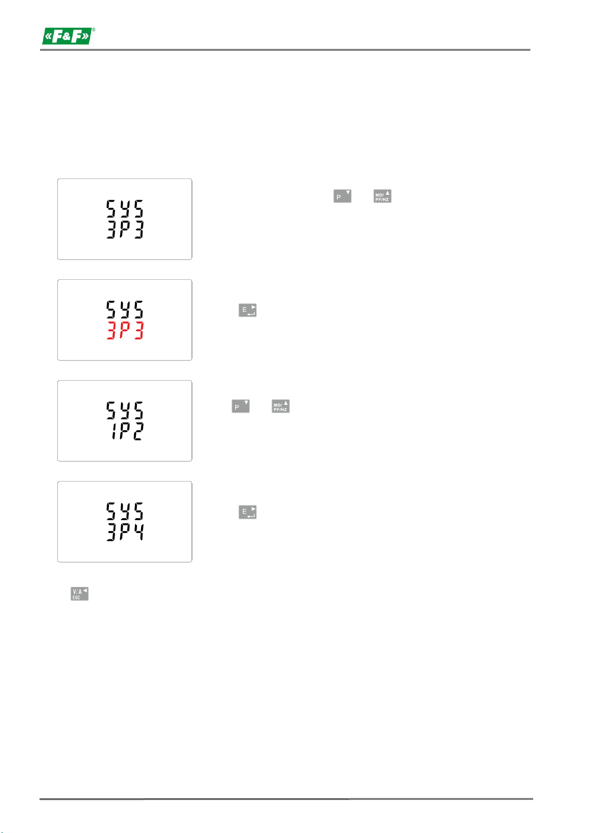
From the set up menu, use and
buttons to select the system option.
The screen will show the currently selected
power supply.
Press to enter the selection routine.
The current selection will flash.
Use and buttons to select the
required system option: 1P2(W), 3P3(W),
3P4(W).
Press to confirm selection.
SET indicator will appear.
5.2.6. Measuring system
Setting options for measuring system:
1P2W – 1-phase 2-wire system;
3P3W – 3-phase 3-wire system (without neutral wire);
3P4W – 3-phase 4-wire system
Press to exit the system selection routine and return to the menu.
SET will disappear and you will be returned to the main set up menu.
18
Page 19
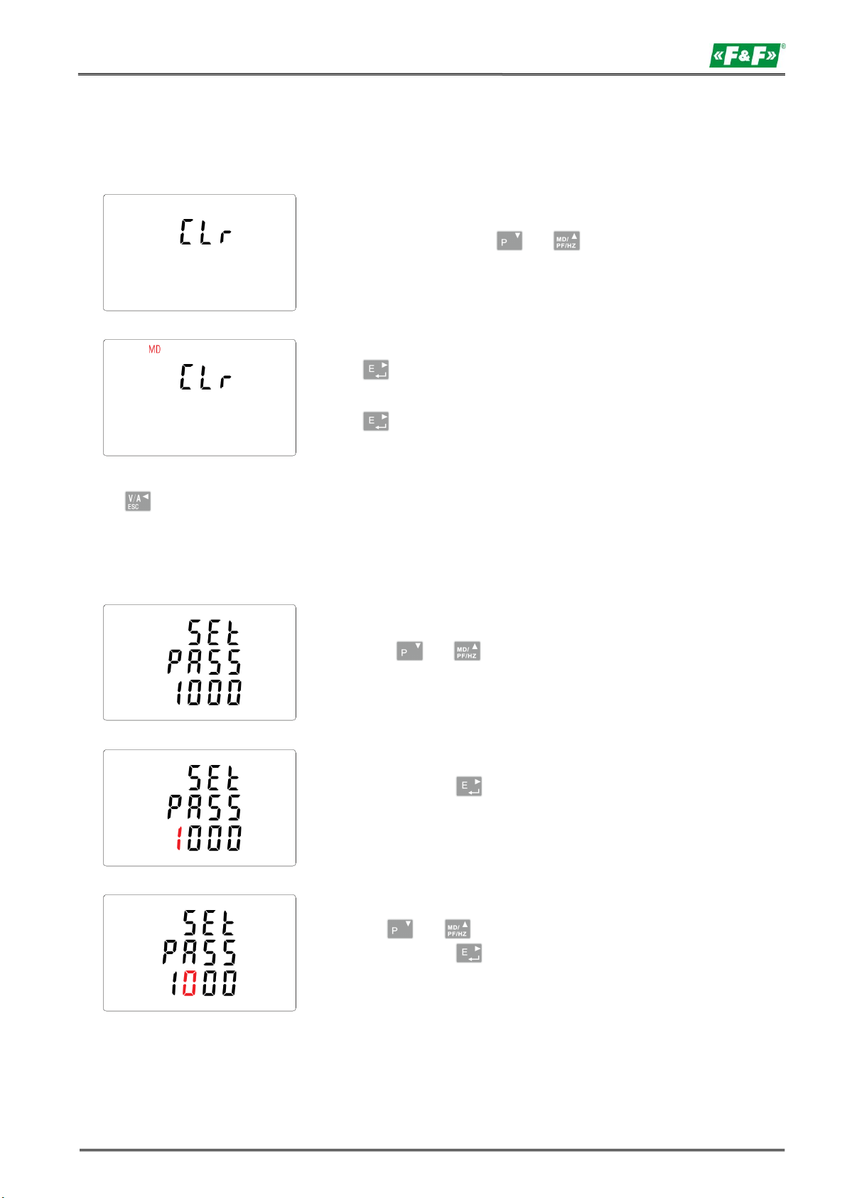
From the setup menu, use and
buttons to select the reset option.
Press to enter the selection routine.
The MD will flash.
Press to confirm selection.
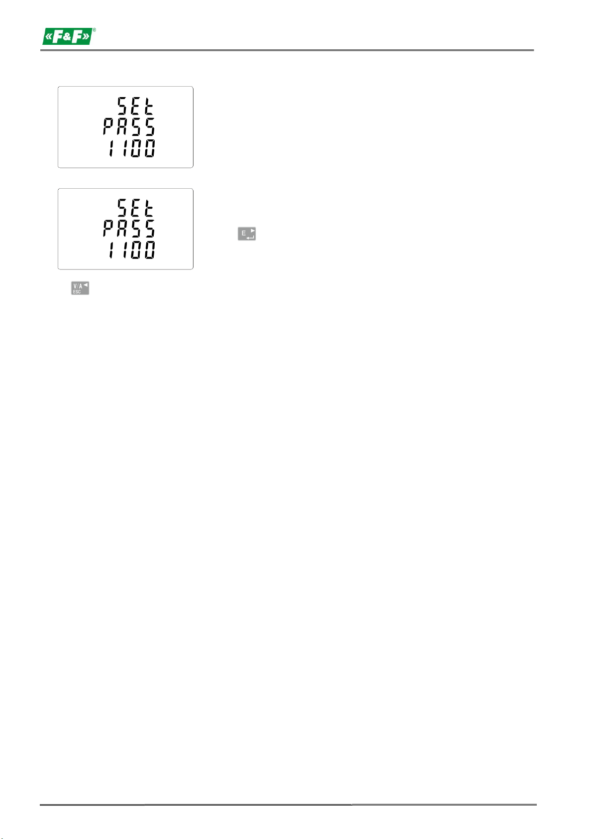
Press and buttons to choose
the change password option.
Press and hold to enter the change
password routine. The new password screen
will appear with the first digit flashing.
Use and buttons to set the first
digit and press to confirm your
selection. The next digit will flash.
LE-03MB - User manual
5.2.7. CLR
The meter provides a function to reset the maximum demand value of current and power.
Press to return to the main set up menu.
5.2.8. Change password
19
Page 20
LE-03MB - User manual
Repeat the procedure for the remaining
three digits.
After setting the last digit, press and hold
to confirm selection.
Press to exit the numer setting routine and return to the setup menu. SET will be removed.
6. Technical specification
6.1. Measured parameters
The unit can monitor and display the following parameters of:
1P2W – 1-phase 2-wire system (230V+N)
3P3W – 3-phase 3-wire system (3×400V; without neutral wire)
3P4W – 3-phase 4-wire system (3×230V+N)
6.1.1. Voltages and currents
Reference voltage: 3×230/400V
Base current: 0.25÷10A
Maximum current: 100A
Minimum current measured: 0.02A
Overload: 30×Imax/10ms
Measuring range phase voltages: 100÷289 VAC (for 1P2W and 3P4W system)
Range of interphase voltages: 173÷500 VAC (for 3P3W system)
Percentage overall factor of total harmonic distortion (THD%) for the phase voltages
(for systems 1P2W and 3P4W).
Percentage overall factor of total harmonic distortion (THD%) for interphase voltages (for 3P3W
system).
Percentage overall factor of total harmonic distortion (THD%) for the phase currents.
Insulation: 4kV/1min; 6kV/1,2µs
20
Page 21

LE-03MB - User manual
6.1.2. Power factor, frequency and maximum demand
Frequency in Hz
Instantaneous power:
active: 0÷3600 MW
reactive: 0÷3600 Mvar
volt-amps: 0÷3600 MVA
Maximum power consumption (with RESET function)
Maximum power consumption neutral wire (with RESET function)
6.1.3. Energy measurements
Imported/exported active energy: 0÷9999999.9 kWh
Imported/exported reactive energy: 0÷9999999.9 kvarh
Total active energy: 0÷9999999.9 kWh
Total reactive energy: 0÷9999999.9 kvarh
6.2. Terminal
Current inputs 2.5mm² screw terminals
Voltage inputs 2.5mm² screw terminals
Pulse outputs 2.5mm² screw terminals
M-Bus port 2.5mm² screw terminals
6.3. Accuracy
Measurement class B
Voltage 0.5% of range maximum
Current 0.5% of nominal
Frequency 0.2% of mid-frequency
Power factor 1% of unity (0.01)
Active power (W) ±1% of range maximum
Reactive power (VAr) ±1% of range maximum
Apparent power (VA) ±1% of range maximum
Active energy (Wh) ±1% 1 IEC 62053-21
Reactive energy (VArh) ±1% of range maximum
Total harmonic distortion 1% up to 31st harmonic
Response time to step input 1s, typical, to >99% of final reading at 50 Hz.
21
Page 22

LE-03MB - User manual
6.4. Power supply and power meter
85÷275 V AC 50/60 Hz ±10%
120÷380 V DC ±20%
<10VA; <2W
6.5. Measurement inputs
Voltage: 3×230V/400V
Current: 100A
6.6. Pulse outputs
Output type: OC (open collector); 27V DC/50mA
Pulse:
Pulse output 1 is configurable: for kWh or kvarh. Value set kWh/kvarh per 1 pulse:
0.01 = 10 Wh/VArh
0.1 = 100 Wh/VArh
1 = 1 kWh/kVArh
10 = 10 kWh/kVArh
100 = 100 kWh/kVArh
1000 = 1000 kWh/kVArh
Pulse output 2 is non-configurable for kWh: 3200pulse/kWh
Pulse width:
Output 1 - configurable: 200 / 100 / 60 ms
Output 2 – non-configurable: 200ms
6.7. M-Bus output
Baud rate: 300, 600, 1200, 2400, 4800, 9600 bps
Parity: NONE - deafault / ODD / EVEN
Stop bits: 1 / 2
Network address: basic 1÷250, expanded 0÷99999999;
6.8. Reference conditions of influence quantities
Influence quantities are variables that effect measurement errors to a minor degree.
Accuracy is verified under nominal value (within the specified tolerance) of these conditions.
Ambient temperature 23°C ±1°C
Input frequency 50 or 60 Hz ±2%
Input waveform sinusoidal (distortion factor <0.005)
Auxiliary supply voltage ±1% nominal
Auxiliary supply frequency ±1% nominal
Auxiliary supply waveform (if AC) sinusoidal (distortion factor <0.05)
Magnetic field of external origin terrestial flux
22
Page 23
LE-03MB - User manual
6.9. Environment
Operating temperature -25÷55°C
Storage temperature -40÷70°C
Relative hummidity 0÷95%, non-condensing
Altitude Up to 3000 m
Warm up time 1 minute
Vibration 10÷50Hz, IEC 60068-2-6, 2 g
Limitation 30g in 3 planes
6.10. Structure
Mounting on DIN rail
Cover Ul94 V-0 self-extinguishing material
Ingress protection IP51 (inside)
6.11. Compliance and sealing
2004/22/EC Directive
Certificate number: 0120/SGS0215
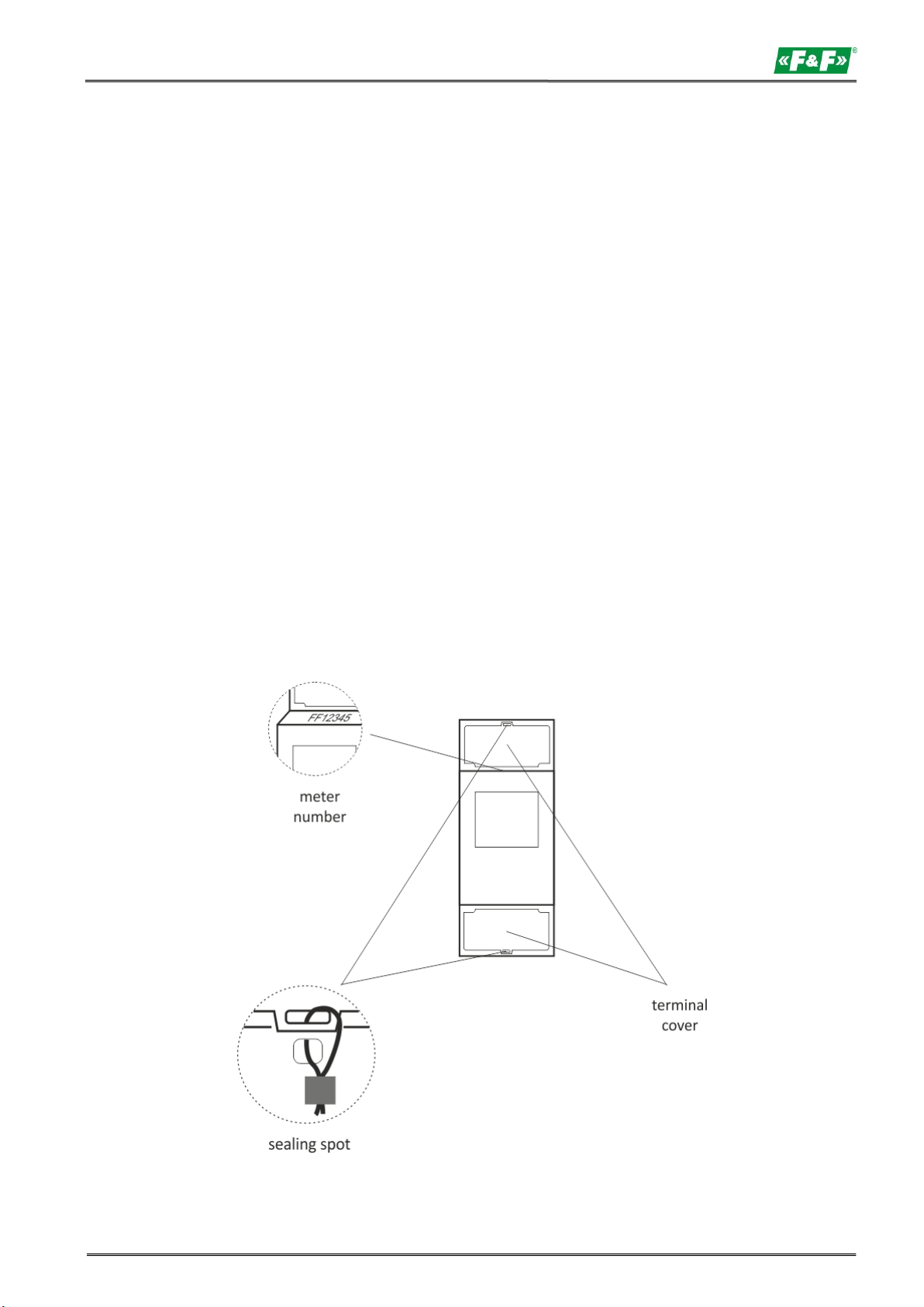
The meter is marked with individual serial numer allowing its explicit identification.
The marking is laser engraved and cannot be removed.
The meter has sealable input and output terminal cover to prevent any attempts to bypass the meter.
23
Page 24
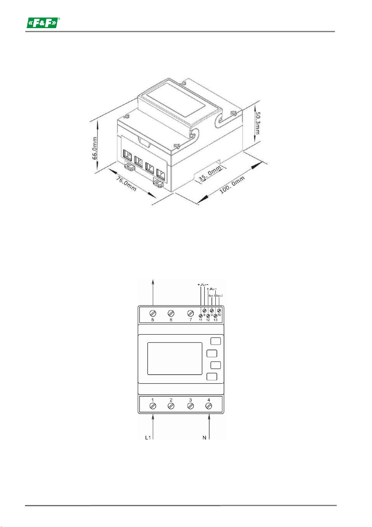
7. Dimensions
LE-03MB - User manual
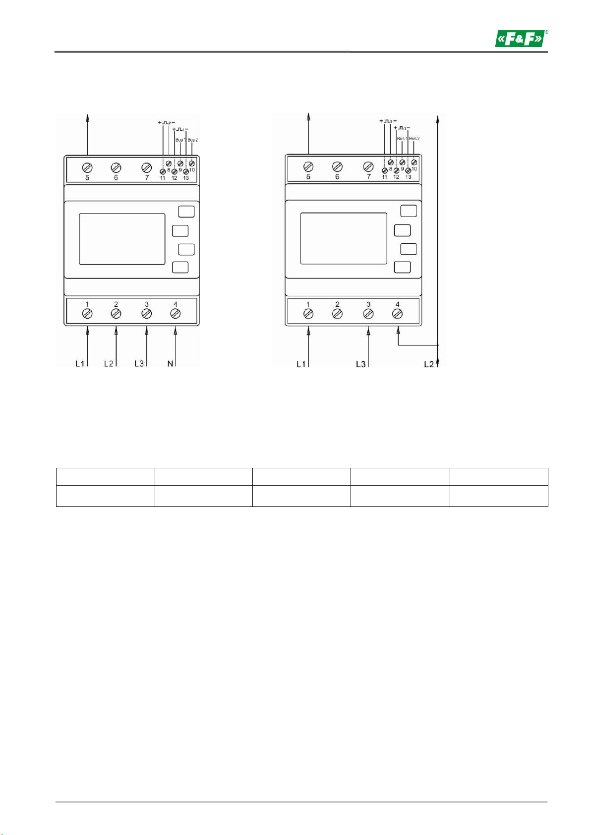
8. Wiring diagram
Single-phase 2-wire
24
Page 25
Start
C field
A field
Check sum
Stop
10
40
XX
CS
16
LE-03MB - User manual
Three-phases 4-wire Three-phases 3-wire
9. M-Bus protocole
9.1. Initialization Slave
Format:
XX=1 to FF
The address field serves to address the recipient in the calling direction,and to identify the sender of information
in the receiving direction. The size of this field is one byte, and can therefore take values from 0 to 255. The
addresses 1 to 250 can be allocated to the individual slaves, up to a maximum of 250. Unconfigured slaves are
given the address 0 at manufacture, and as a rule are allocated one of these addresses when connected to the
M-Bus. The addresses 254 (FE) and 255 (FF) are used to transmit information to all participants (Broadcast). With
address 255 none of the slaves reply, and with address 254 all slaves reply with their own addresses. The latter
case naturally results in collisions when two or more slaves are connected, and should only be used for test
purposes. The address 253 (FD) indicates that the addressing has been performed in the Network Layer instead
of Data Link Layer, the FD used when using the second level address. The remaining addresses 251 and 252 have
been kept for future applications.
25
Page 26

LE-03MB - User manual
Start
L field
L field
Start
C field
A field
CI field
Check sum
Stop
68H
03
03
68H
53/73
FE
B8-BD
CS
16
9.1.1. How to initialize a meter which you don’t know the address
Master to Slave: 10 40 FE 3E 16
Slave to Master: E5 (success)
9.1.2. Remove the secondary address matching symbol of all the meters on Bus
Master to Slave: 10 40 FD 3D 16
Slave: No answer
9.1.3. How to initialize all meters on the bus line by using FF as broadcast address
Master to Slave: 10 40 FF 3F 16
Slave: No answer
9.1.4. How to initialize a Slave with specific address
Example: address 01
Master to Slave: 10 40 01 41 16
Slave to Master: E5
9.2. How to set baud rate
9.2.1. Point to point baud-rate setting command format (Control frame)
L field - Byte length
C field - Control field, function field
A field - Address field
CI field - Control information field
Check sum - The Check sum is calculated from the arithmetical sum of the data mentioned above,
without taking carry digits into account.
B8-------300
B9-------600
BA-------1200
BB-------2400
BC-------4800
BD-------9600
Example: (Meter address is 01)
(1) How to change baud rate to 2400 bps.
Master to Slave: 68 03 03 68 53 01 BB 0F 16
Slave to Master: E5
(2) How to change baud rate to 9600 bps.
Master to Slave: 68 03 03 68 53 01 BD 11 16
Slave to Master: E5
26
Page 27

Start
L field
L field
Start
C field
A field
CI field
Check sum
Stop
68H
03
03
68H
53/73
FF
B8-BD
CS
16
Start
L field
L field
Start
C field
A field
CI field
DIF
VIF
Address
data
Check
sum
Stop
68H
06
06
68H
53/73
FE
51
01
7A
XX
CS
16
Start
L field
L field
Start
C field
A field
CI field
DIF
VIF
Address
data
Check
sum
Stop
68H
06
06
68H
53/73
FF
51
01
7A
XX
CS
16
LE-03MB - User manual
9.2.2. How to use broadcast command to set baud rate
Format:
Slave to Master: No answer
B8-------300
B9-------600
BA-------1200
BB-------2400
BC-------4800
BD-------9600
Example:
Change all the meter's baud rate to 2400 bps.
Master to Slave: 68 03 03 68 53 FF BB 0D 16
Slave to Master: No answer
9.3. How to set primary address
9.3.1. How to set the address of a Slave to 01
Format:
Example:
Master to Slave: 68 06 06 68 53 FE 51 01 7A 01 1E 16
Slave to Master: E5
9.3.2. How to use broadcast command to set primary address to 01
Format:
Example:
Master to Slave: 68 06 06 68 53 FF 51 01 7A 01 1F 16
Slave: No answer
27
Page 28

LE-03MB - User manual
Start
L field
L field
Start
C field
A field
CI field
DIF
VIF
Address
data
Check
sum
Stop
68H
06
06
68H
53/73
XX
51
01
7A
YY
CS
16
Start
L field
L field
Start
C field
A field
CI field
DIF
VIF
68H
0D
0D
68H
53/73
addr
51
07
79
Identification
No
Manufacturer
ID
Generation
Medium
Check
sum
Stop
4 byte
2 byte
1 byte
1 byte
CS
16
9.3.3. How to change address from 01 to 02
Format:
XX - current primary address
YY - new primary address
Master to Slave: 68 06 06 68 73 01 51 01 7A 02 42 16
Slave to Master: E5
9.3.4. How to set primary address to 01 by using secondary address
Example: secondary address: 12345678
Step 1
Initialize the Slave
Master to Slave: 10 40 FF 3F 16
Slave to Master: No answer
Step 2
Check the secondary address. After receiving the command, the Slave will check if the secondary address in the
command is same with its secondary address or not.
Master to Slave: 68 0B 0B 68 73 FD 52 78 56 34 12 FF FF FF FF D2 16
FD --- the primary address used when you use secondary address to read data.
78 56 34 12 - the meter’s secondary address is 12 34 56 78
Master to Slave: E5 (success)
Step 3
Change the primary address to 01
Master to Slave: 68 06 06 68 73 FD 51 01 7A 01 3D
01 --- new primary address
Slave to Master: E5
9.4. Set the complete identification of the Slave
(ID=12345678, Man=4024h (PAD), Gen=1, Med=02 (energy)
For example: (Meter address is 01)
Master to Slave: 68 0D 0D 68 53 01 51 07 79 78 56 34 12 24 40 01 02 A0 16
Slave to Master: E5
28
Page 29

LE-03MB - User manual
9.5. How to read out of energy information
9.5.1. Use primary address 01 to read energy information
Format:
Master to Slave: 10 7B/5B ad r CS 16
Slave to Master: Variable data structure
Example: 10 7B 01 7C 16
9.5.2. How to read out a meter’s energy information by using broadcast address 254 (FE)
Master to Slave: 10 7B/5B FE CS 16
Slave to Master: Variable data structure
Example: 10 5B FE 59 16
9.5.3. How to read out the meter’s energy information by using secondary addres
Example:
Secondary address: 12 34 56 78
Step 1
Initialize the Slave
Master to Slave: 10 40 FF 3F 16
Slave to Master: No answer
Step 2
Check the secondary address. After receiving the command, the slave will check if the secondary address in the
command is same with its secondary address or not.
Master to Slave: 68 0B 0B 68 73 FD 52 78 56 34 12 FF FF FF FF D2 16
Slave to Master: E5
Step 3
Read the energy information
Master to Slave: 10 7B FD 78 16
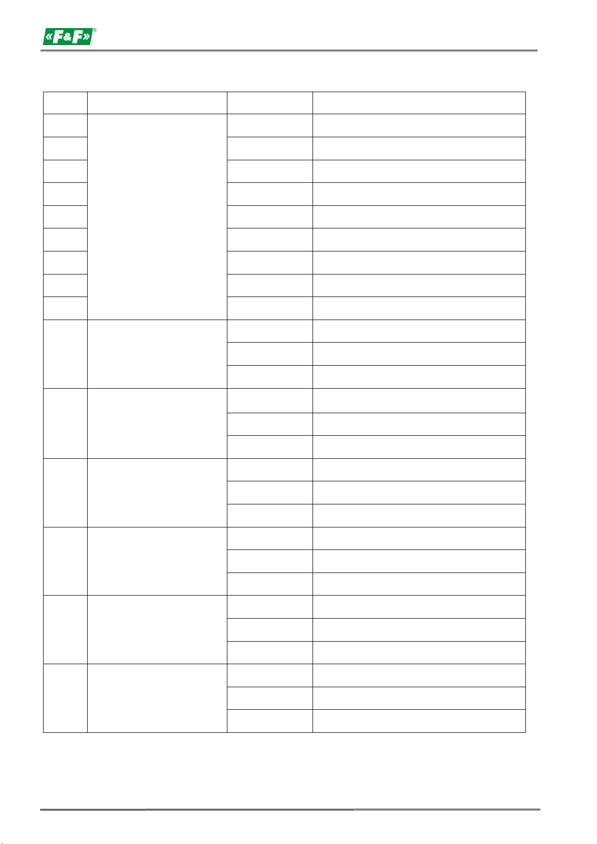
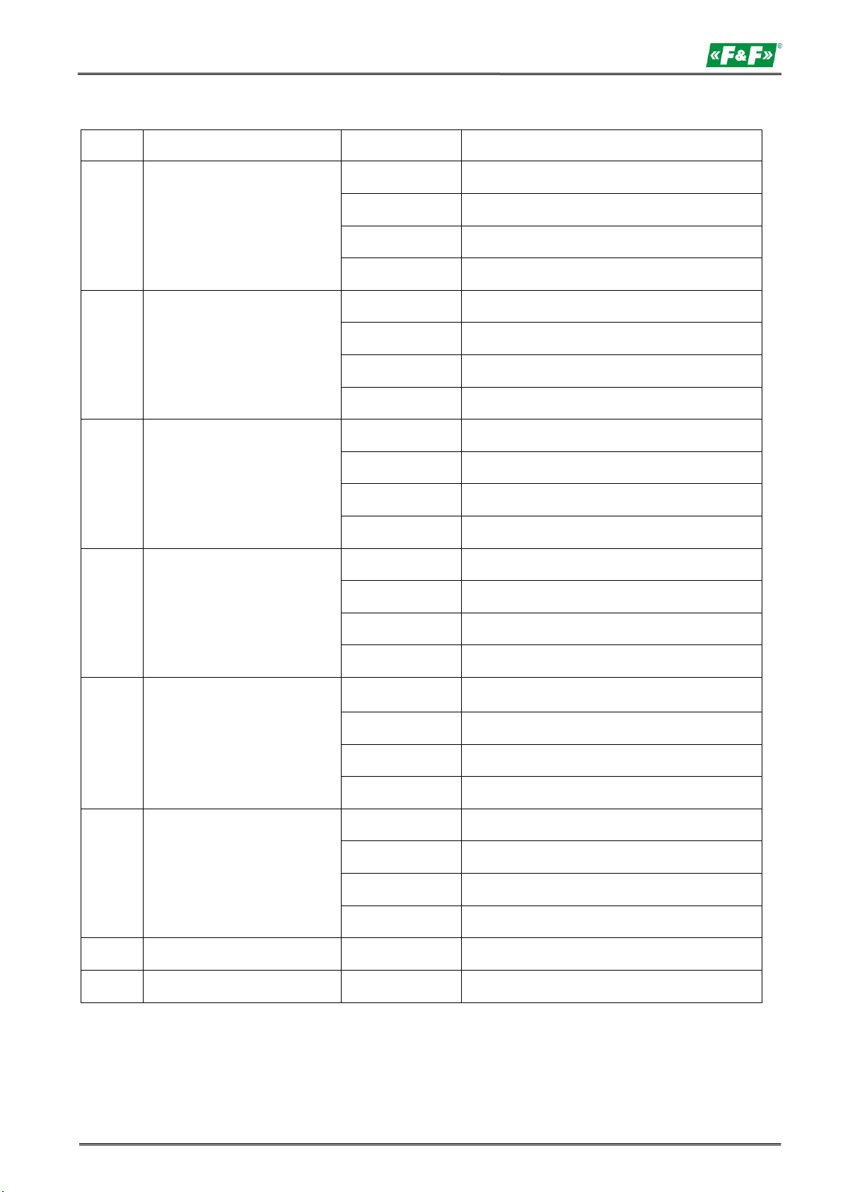
Slave to Master: DIF===== Coding of the Data Information Field
VIF===== Codes for Value Information Field
29
Page 30
LE-03MB - User manual
Bytes
Parameters
Data structure
Notice
4
Header telegram
68 5D 5D 68
Header of RSP_UD telegram
3
08 A 72
C field=08 address A CI field 72
4
78 65 34 21
Identification number =12345678
2
24 40
Manufacturer ID 4024
1
01
Generation 1
1
02
Energy meter
1
55
ACCESS NO
1
00
STATUS
2
00 00
Signaturе
6
Current total
active energy
0C
DIF: 8 digit BCD , Current value
04
VIF: 10 W (0.01 kW)
78 56 34 12
123456.78 kWh
7
Current import
active energy
0C
DIF: 8 digit BCDFIE, Current value
04
VIF: 10 W (0.01 kW)
78 56 34 12
123456.78 kWh
7
Current export
active energy
0C
DIF: 8 digit BCDFIE, Current value
04
VIF: 10 W (0.01 kW)
78 56 34 12
123456.78 kWh
6
Current resettable total
active energy
0C
DIF: 8 digit BCD, Current value
04
VIF: 10 W (0.01 kW)
78 56 34 12
123456.78 kWh
7
Current resettable import
active energy
0C
DIF: 8 digit BCDFIE, Current value
04
VIF: 10 W (0.01 kW)
78 56 34 12
123456.78 kWh
7
Current resettable export
active energy
0C
DIF: 8 digit BCDFIE, Current value
04
VIF: 10 W (0.01 kW)
78 56 34 12
123456.78 kWh
30
Page 31
Bytes
Parameters
Data structure
Notice
7
Current total
reactive energy
0C
DIF: 8 digit BCD , Current value
FD
VIF: FD
3A
VIFE: bezwymiarowe / no VIF
78 56 34 12
123456,78 kVarh
8
Current import
reactive energy
0C
DIF: 8 digit BCDFIE, Current value
FD
VIF: FD
3A
VIFE: dimensionless / no VIF
78 56 34 12
123456.78 kVarh
8
Current export
reactive energy
8C
DIF: 8 digit BCDFIE, Current value
FD
VIF: FD
3A
VIFE: dimensionless / no VIF
78 56 34 12
123456.78 kVarh
7
Current total resettable
reactive energy
0C
DIF: 8 digit BCD, Current value
FD
VIF: FD
3A
VIFE: dimensionless / no VIF
78 56 34 12
123456.78 kVarh
8
Current resettable import
reactive energy
0C
DIF: 8 digit BCDFIE, Current value
FD
VIF: FD
3A
VIFE: dimensionless / no VIF
78 56 34 12
123456.78 kVar
8
Current resettable export
reactive energy
0C
DIF: 8 digit BCDFIE, Current value
FD
VIF: FD
3A
VIFE: dimensionless / no VIF
78 56 34 12
123456.78 kVar
1
CHECK SUM
CS 1
End
16
LE-03MB - User manual
31
Page 32

LE-03MB - User manual
Start
L field
L field
Start
C field
A field
CI field
Check sum
Stop
68H 3 3
68
53/73
XX
B1
CS
16
9.6. Read out of instantaneous electrical information
The instantaneous electrical information includes:
V, I, P, Q, S, PF, Hz ect. MD
9.6.1. How to read instantaneous electrical information by using primary address
Master to Slave: 68 03 03 68 53 XX B1 05 16
Slave to Master: Variable data structure (instantaneous electrical information)
If the primary address is 01, then XX=01
9.6.2. How to use secondary address to read out the instantaneous electrical information
Step 1
Initialization Slave
Master to Slave: 10 40 FF 3F 16
Slave to Master: No answer
Step 2
Check the secondary address. After receiving the command, the slave will check if the secondary address in
the command is same with its secondary address or not.
Master to Slave: 68 0B 0B 68 73 FD 52 78 56 34 12 FF FF FF FF D2 16
Slave to Master: E5
Step 3
Use Secondary Address to read out the instantaneous electrical information
Master to Slave: 68 03 03 68 53 FD B1 01 16
Slave to Master: Variable data structure
32
Page 33
Bytes
Parameters
Data structure
Notice
4
Header telegram
68 90 90 68
Header of RSP_UD telegram
3
08 A 72
C field =08 address A CI field 72
4
78 65 34 21
Identification number =12345678
2
24 40
Manufacturer ID 4024
1
01
Generation 1
1
02
Energy meter
1
55
ACCESS NO
1
00
STATUS
2
00 00
Signature
6
L1 voltage
0B
DIF: 6 digit BCD
FD
VIF: FD
47
VIFE: 0.01 V
56 34 12
1234.56 V
6
L2 voltage
0B
DIF: 6 digit BCD
FD
VIF: FD
47
VIFE: 0.01 V
56 34 12
1234.56 V
6
L3 voltage
0B
DIF: 6 digit BCD
FD
VIF: FD
47
VIFE: 0,01 V
56 34 12
1234,56 V
6
L1 - L2 Voltage
0B
DIF: 6 digit BCD
FD
VIF: FD
47
VIFE: 0.01 V
56 34 12
1234.56 V
LE-03MB - User manual
33
Page 34
LE-03MB - User manual
Bytes
Parameters
Data structure
Notice
6
L2 - L3 Voltage
0B
DIF: 6 digit BCD
FD
VIF: FD
47
VIFE: 0.01 V
56 34 12
1234.56 V
6
L3 - L1 Voltage
0B
DIF: 6 digit BCD
FD
VIF: FD
47
VIFE: 0.01 V
56 34 12
1234.56 V
6
L1 current
0B
DIF: 6 digit BCD
FD
VIF: FD
59
VIFE: 1 mA (xxx.xxx A)
56 34 12
123456 mA (123.456 A)
6
L2 current
0B
DIF: 6 digit BCD
FD
VIF: FD
59
VIFE: 1 mA (xxx.xxx A)
56 34 12
123456 mA (123.456 A)
6
L3 current
0B
DIF: 6 digit BCD
FD
VIF: FD
59
VIFE: 1 mA (xxx.xxx A)
56 34 12
123456 mA (123.456 A)
6
N current
0B
DIF: 6 digit BCD
FD
VIF: FD
59
VIFE: 1 mA (xxx.xxx A)
56 34 12
123456mA (123.456A)
5
Total active power
0B
DIF: 6 digit BCD
2A
VIF: 0.1 W (xx.xxxx kW)
56 34 12
12345.6 W (12.3456 kW)
34
Page 35
Bytes
Parameters
Data structure
Notice
5
L1 active power
0B
DIF: 6 digit BCD
2A
VIF: 0.1 W (xx.xxxx kW)
56 34 12
12345.6 W (12.3456 kW)
5
L2 active power
0B
DIF: 6 digit BCD
2A
VIF: 0.1 W (xx.xxxx kW)
56 34 12
12345.6 W (12.3456 kW)
5
L3 active power
0B
DIF: 6 digit BCD
2A
VIF: 0,1 W (xx.xxxx kW)
56 34 12
12345.6 W (12.3456 kW)
6
Total reactive power
0B
DIF: 6 digit BCD
FD
VIF: FD
3A
VIFE: dimensionless / no VIF
56 34 12
12345.6 W (12.3456 kW)
6
L1 reactive power
0B
DIF: 6 digit BCD
FD
VIF: FD
3A
VIFE: dimensionless / no VIF
56 34 12
12345.6 W (12.3456 kW)
6
L2 reactive power
0B
DIF: 6 digit BCD
FD
VIF: FD
3A
VIFE: dimensionless / no VIF
56 34 12
12345.6 W (12.3456 kW)
6
L3 reactive power
0B
DIF: 6 digit BCD
FD
VIF: FD
3A
VIFE: dimensionless / no VIF
56 34 12
12345.6 W (12.3456 kW)
LE-03MB - User manual
35
Page 36
LE-03MB - User manual
Bytes
Parameters
Data structure
Notice
5
Total power factor
0A
DIF: 4 digit BCD
FD
VIF: FD
3A
VIFE: dimensionless / no VIF
00 05
0.500
5
A power factor
0A
DIF: 4 digit BCD
FD
VIF: FD
3A
VIFE: dimensionless / no VIF
00 05
0.500
5
B power factor
0A
DIF: 4 digit BCD
FD
VIF: FD
3A
VIFE: dimensionless / no VIF
00 05
0.500
5
C power factor
0A
DIF: 4 digit BCD
FD
VIF: FD
3A
VIFE: dimensionless / no VIF
00 05
0.500
5
Frequency
0A
DIF: 4 digit BCD
FD
VIF: FD
3A
VIFE: dimensionless / no VIF
00 50
50.00 Hz
1
End
CS 1
16
36
Page 37

Start
L field
L field
Start
C field
A field
CI field
Check sum
Stop
68 3 3
68
11
addr
03
CS
16
Start
L field
L field
Start
C field
A field
CI field
Data
Check sum
Stop
68 5 5
68
11
addr
04
password H
password L
CS
16
Start
L field
L field
Start
C field
A field
CI field
Check sum
Stop
68 3 3
68
11
addr
0D
CS
16
Start
L field
L field
Start
C field
A field
CI field
DIF
VIF
Data
Check sum
Stop
68H
09
09
68H
53/73
FE
51
30
01
Demand interval,
slide time,display
time, LED time
Display time=0:
the display does
not scroll
automatically.
LED time=0:
Backlight always
on min-min-s-min
4 bytes
CS
16
LE-03MB - User manual
9.7. How to read password
Master to Slave: 68 03 03 68 11 address 03 cs 16
Slave to Master: 68 05 05 68 11 address 03 passwordH passwordL cs 16
9.7.1. Change to a new password
Master to Slave: 68 05 05 68 11 address 04 passwordH passwordL cs 16
Slave to Master: E5
9.8. How to reset all resettable energy data
Example: addr: 01
Master to Slave: 68 03 03 68 11 01 0D 1F 16
Slave to Master: E5
9.9. Set demand interval, slide time, display time, LED time
Send: 68 09 09 68 53 FE 51 30 01 60 01 05 06 3F 16
Example: (Meter address is 01)
Master do Slave: 68 09 09 68 53 FE 51 30 01 60 01 05 06 3F 16
Slave to Master: E5
37
Page 38
LE-03MB - User manual
Start
L field
L field
Start
C field
A field
CI field
DIF
VIF
Check sum
Stop
68H
05
05
68H
53/73
FE
51
30
81
CS
16
Bytes
Parameters
Data structure
Notice
4
Header telegram
68 16 16 68
Header telegram RSP_UD
3
08 A 72
C field =08 address A CI field72
4
78 65 34 21
Identification number =12345678
2
24 40
Manufacturer ID 4024
1
01
Generation 1
1
02
Energy meter
1
55
ACCESS NO
1
00
STATUS
2
00 00
Signature
7
Demand interval,
slide time,
display time, LED time
0A
DIF: 30 digit BCD
FD
VIF: FD
3A
VIFE: dimensionless / no VIF
15010610
Demand interval: 15 min.
Slide time: 01 min.
Display time: 06 sec
LED time: 10 sec
1
CHECK SUM
CS 1
End
16
9.10. Read demand interval,slide time, display time, LED time
Example: (Meter address is 01)
Master to Slave: 68 05 05 68 53 FE 51 30 81 53 16
Slave to Master: E5
38
Page 39

Start
L field
L field
Start
C field
A field
CI field
Data
Check sum
Stop
68
03
03
68
11
addr
09
01/02/03
CS
16
Start
L field
L field
Start
C field
A field
C field
Data
Check sum
Stop
68
04
04
68
11
addr
0A
01/02/03
CS
16
Start
L field
L field
Start
C field
A field
C field
Check sum
Stop
68
03
03
68
11
addr
10
CS
16
LE-03MB - User manual
9.11. Read the measurement mode
Example: (Meter address is 01)
Master to Slave: 68 03 03 68 11 01 09 1B 16
Slave to Master: 68 04 04 68 11 01 09 01 1C 16
The red-lighted 01 represents the measurement mode:
01: means active energy
02: means active energy + reactive energy
03: means active energy - reactive energy
9.12. Set up the measurement mode
Example: (Meter address is 01)
Master to Slave: 68 04 04 68 11 01 0A 01 1C 16
Slave to Master: E5
The red-lighted 01 represents the measurement mode:
01: means active energy
02: means active energy + reactive energy
03: means active energy - reactive energy
9.13. Read the output mode of pulse 1
Example: (Meter address is 01)
Master to Slave: 68 03 03 68 11 01 10 22 16
Slave to Master: 68 04 04 68 11 01 10 01 23 16
The red-lighted 01 represents the output mode of pulse 1:
01: Import active energy
02: Import + export active energy
04: Export active energy (default)
05: Import reactive energy
06: Import + export reactive energy
08: Export reactive energy
39
Page 40

LE-03MB - User manual
Start
L field
L field
Start
C field
A field
C field
Data
Check
sum
Stop
68
08
08
68
11
addr
11
01/02/04/05/06/08
CS
16
Start
L field
L field
Start
C field
A field
C field
Check
sum
Stop
68
03
03
68
11
addr
12
CS
16
Start
L field
L field
Start
C field
A field
C field
Data
Check
sum
Stop
68
08
08
68
11
addr
11
00/01/02/03/04/05
CS
16
9.14. Set up the output mode of pulse 1
Example: (Meter address is 01)
Master to Slave: 68 04 04 68 11 01 11 01 24 16
Slave to Master: E5
The red-lighted 01 represents the output mode of Pulse1:
01: Import active energy
02: Import + export active energy
04: Export active energy (default)
05: Import reactive energy
06: Import + export reactive energy
08: Export reactive energy
9.15. Read the constant of pulse 1
Example: (Meter address is 01)
Master to Slave: 68 03 03 68 11 01 12 24 16
Slave to Master: 68 04 04 68 11 01 10 00 22 16
The red-lighted 00 represents the constant of pulse 1:
00: 0.0025 kwh (kvarh)/pulse (default)
01: 0.01 kWh (kvarh)/pulse
02: 0.1 kWh (kvarh)/pulse
03: 1 kWh (kvarh)/pulse
04: 10 kWh (kvarh)/pulse
05: 100 kWh (kvarh)/pulse
9.16. Set up the constant of pulse 1
Example: (Meter address is 01)
Master to Slave: 68 04 04 68 11 01 13 00 25 16
Slave to Master: E5
40
Page 41

LE-03MB - User manual
The red-lighted 00 represents the constant of pulse 1:
00: 0.0025 kwh (kvarh)/pulse (default)
01: 0.01 kwh (kvarh)/pulse
02: 0.1 kwh (kvarh)/pulse
03: 1 kwh (kvarh)/pulse
04: 10 kwh (kvarh)/pulse
05: 100 kwh (kvarh)/pulse
10. Manufacturer's warranty
1. The product is covered by 24 month warranty from the date of purchase.
2. The warranty is valid only with a proof of purchase.
3. The notification of the complaint must be made at the place of purchase or directly at the manufacturer:
(phone: +48 (42) 227 09 71; e-mail: [email protected])
4. During the warranty period in the case of a justified complaint the manufacturer commits in accordance with
the provisions of the consumer rights to repair the product, replace it with a new one or refund.
5. The complaint will be processed within 14 days from the date of delivering the product to the service point.
6. Warranty does not cover:
- mechanical and chemical damages;
- damages resulting from improper use or from the use inconsistent with the user manual;
- damages incurred after the sale as a result of accidents or other events for which nor the producer, nor the
place of sale are responsible, for example damages in transit, etc.
7. Warranty does not cover actions that user should perform in accordance with the user manual, for example
installing multi-meter, building electrical installation, installing other required electrical protection, checking,
etc.
Warning!
Do not make any changes in the device by yourself. This may cause damage or improper operation of the device,
which can lead to damage to the controlled device and may pose a danger to the operators. In such cases, the
manufacturer is not liable for consequential events and may refuse the guarantee in case of complaint.
41
 Loading...