

Page 1

Warning: Please read this entire manual before riding your Simbi.
Failure to do so could result in serious injury or even death.
Page 2

Contents
1. OVERVIEW ....................................................................................................................................... 3
A. Thank You ....................................................................................................................................... 3
B. General Warning .............................................................................................................................. 3
C. Important Symbols and Terms ........................................................................................................... 4
D. Related Manuals ............................................................................................................................... 4
2. UNPACKING ..................................................................................................................................... 5
A. Box Contents ................................................................................................................................... 5
B. Initial Inspection .............................................................................................................................. 5
C. Registration ..................................................................................................................................... 8
3. ASSEMBLY ........................................................................................................................................ 9
A. Quick Assembly Overview .................................................................................................................. 9
B. Step 1 - Attach Front Wheel .............................................................................................................. 10
C. Step 2 - Attach Handlebar ................................................................................................................ 12
D. Step 3 - Attach Pedals...................................................................................................................... 14
E. Step 4 - Inflate Tires ........................................................................................................................ 16
F. Step 5 - Attach Seat ........................................................................................................................ 17
G. Step 6 - Attach Additional Reflectors .................................................................................................. 20
4. OPERATION .................................................................................................................................... 21
A. Before Riding – Important Safety Information ..................................................................................... 21
5. MAINTENANCE ............................................................................................................................... 23
A. Inspecting ...................................................................................................................................... 23
B. Brake Adjustments .......................................................................................................................... 23
C. Gears ............................................................................................................................................. 25
D. Pedals ............................................................................................................................................ 25
E. Wheels ........................................................................................................................................... 26
F. Lubrication ..................................................................................................................................... 26
Page 3

G. Cleaning ......................................................................................................................................... 27
H. Storage .......................................................................................................................................... 27
I. Baby your Simbi .............................................................................................................................. 28
6. SIMBI LIMITED WARRANTY ........................................................................................................... 29
A. Warranty Information ...................................................................................................................... 29
7. TORQUE MEASUREMENT TABLES .................................................................................................... 30
A. Technical Torque Measurements ........................................................................................................ 30
8. SUPPORT ........................................................................................................................................ 32
A. Simbi Contact Information ................................................................................................................ 32
9. INDEX ............................................................................................................................................ 33
10. TABLE OF FIGURES ......................................................................................................................... 34
11. INDEX OF TABLES .......................................................................................................................... 35
Page 4
1 - Overview
3
1. OVERVIEW
A. Thank You
Thank you for purchasing a Simbi Bicycle by Fezzari®.
Simbi bicycles are handmade of the finest components.
Simbi was founded on the premise that discerning
customers will embrace products of superior
performance, quality, and value. We hope you
appreciate your Simbi experience. We want this to be
the most rewarding purchase you have ever made. If
you have any feedback, comments, or questions, we
look forward to hearing from you.
B. General Warning
In order to use and enjoy your Simbi bicycle
safely and to get the best durability and
performance, please read this manual carefully
before riding.
The information contained in this manual is to be
used as a guideline for safe operation and is not
intended to replace any safety rules or laws that
may be in force in your area.
Even if you have ridden a bicycle for years, it is
important for every person to read this manual before
you ride your new bicycle.
New information will be made available on the Simbi
website (www.SimbiBicycles.com) as it is available.
Assembly and adjustments of your Simbi take special
tools and skills, so please read carefully.
Page 5
1 - Overview
4
C. Important Symbols and Terms
Bicycling can be a hazardous activity even under
the best of circumstances. Properly maintaining
your Simbi is your responsibility and will help
reduce the risk of injury. This manual contains
many symbols, terms, and formatting to call
attention to warnings and cautions.
The Warning sign indicates a
potentially hazardous situation
that, if not avoided, could
result in death or serious
injury.
The Caution sign indicates a
potentially hazardous situation
that, if not avoided, could
result in minor or moderate
injury.
The Note sign indicates text
that provides helpful or other
important information.
BOLD
Bold lettering indicates
important text and points to
note.
Please read and follow all Warnings and Cautions
in this manual.
D. Related Manuals
Some of the Simbi components may have separate
manuals that provide additional information. These
manuals were included with your Simbi or may be
online at www.SimbiBicycles.com. Please read and
follow the information in these manuals.
Page 6
2- Unpacking
5
2. UNPACKING
A. Box Contents
Following is a list of all packaging contents shipped
with your Simbi:
Simbi Bicycle Frame (with rear wheel
attached)
Saddle and Seatpost
Handlebars
Front Wheel
Box containing:
o Pedals (left and right)
o Front Wheel Axle
o Tools needed to assemble your Simbi
4mm, 5mm, and 6mm Allen
Wrenches (for installing and
adjusting handlebars, brakes,
and seatpost)
15mm Wrench (for attaching
pedals)
o Component manuals
o Extra parts
B. Initial Inspection
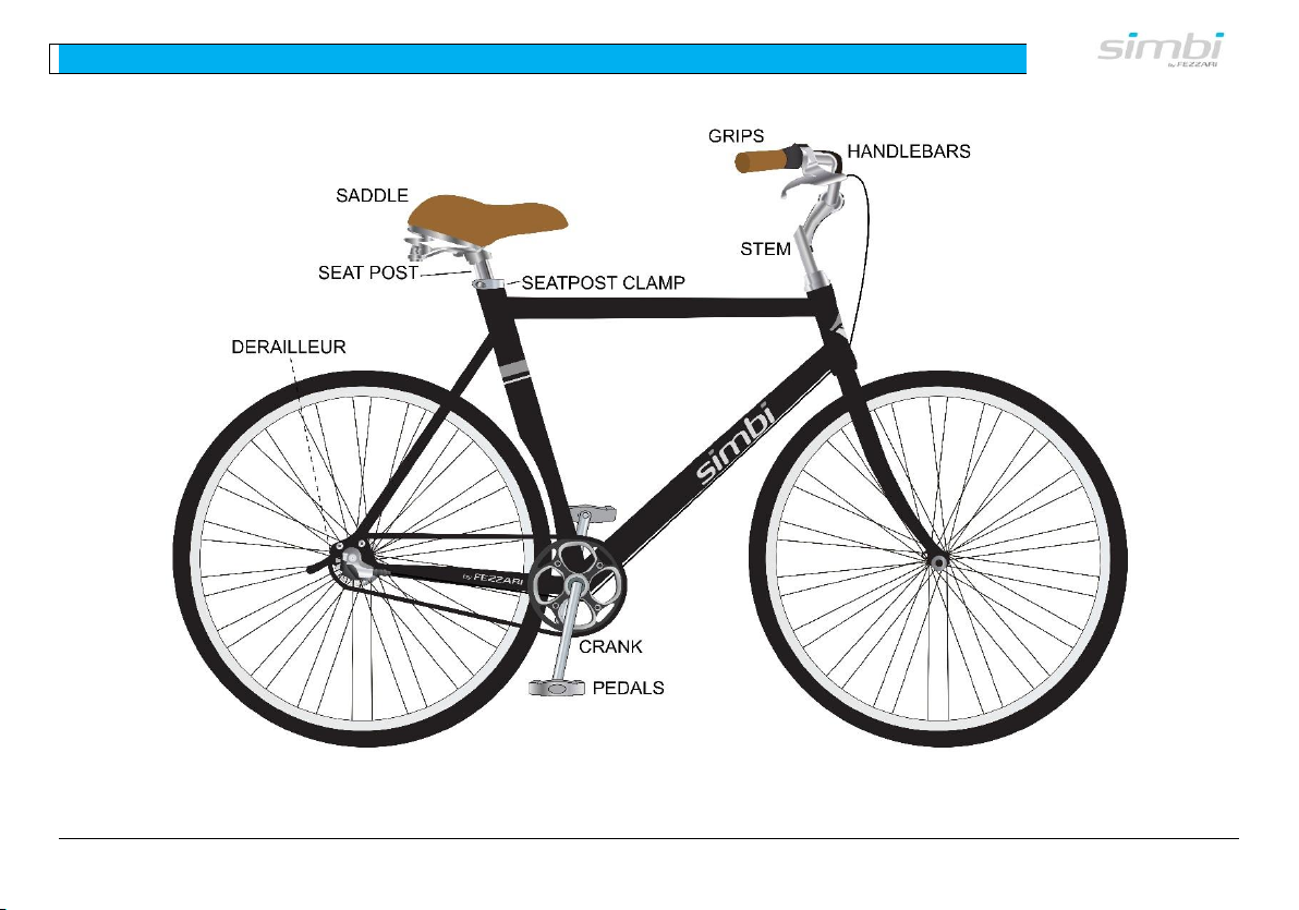
All major parts are identified in
Figure 1. Please familiarize yourself with these parts
prior to assembling or riding your Simbi. Please check
your Simbi along with the parts and components
thoroughly for any damage that may have been
sustained during shipping. Be careful to avoid
scratching the frame when untying or unpacking the
bicycle and components.
If you find that something is missing or
damaged, please contact the Simbi Customer
Support Team at (888) 833-9927.
Page 7
2- Unpacking
6
Figure 1 - Names and Locations of Parts
Page 8
2- Unpacking
7
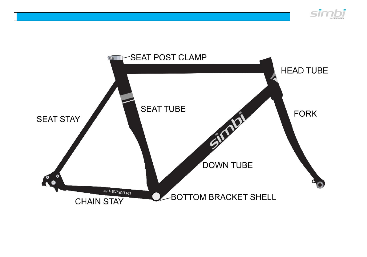
For your information, Figure 2 references commonly-used terms for the frame parts of your Simbi.
Figure 2 - Names of Frame Parts
Page 9

2- Unpacking
8
C. Registration
The serial number of your bicycle frame is attached to the underside of the down tube or underneath the bottom
bracket shell (see Figure 2 and Error! Reference source not found.).This information is required for you to register
your bike. We must have this registration before we can process a warranty claim. Please fill out the warranty
registration form online at www.SimbiBicycles.com. Your Simbi must be registered before a warranty claim can be
processed.
Page 10
3 - Assembly:
9
3. ASSEMBLY
A. Quick Assembly Overview
All references to “left” and “right” in this
manual are relative to riding position on the
bicycle.
Your Simbi comes with tools needed for assembly.
Assembly is generally a 5 or 6 step process (note: you
don’t necessarily need to do these in this order):
Step 1 - Attach Front Wheel
Step 2 - Attach Handlebar
Step 3 - Attach Pedals
Step 4 - Inflate Tires
Step 5 - Attach Seat
Page 11
3 - Assembly:
10
Step 6 - Attach Additional Reflectors
If you have any problems or questions with
assembly
Call (888) 833-9927
or visit www.SimbiBicycles.com.
Page 12
3 - Assembly: Step 1 - Attach Front Wheel
11
B. Step 1 - Attach Front Wheel
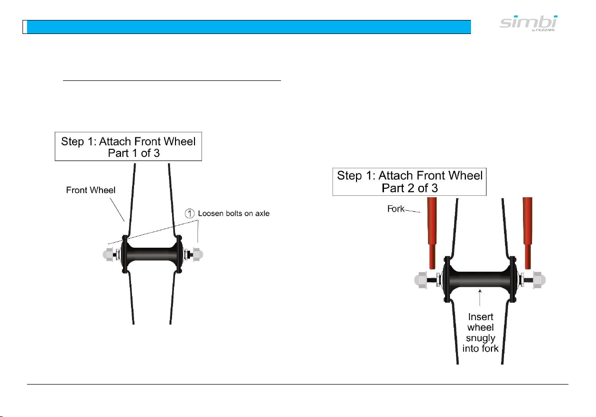
(1) Loosen axle bolts (See Figure 3). Loosen the
axle bolts so that the fork wheel will install
onto the fork.
Figure 3 – Loosen Axle Bolts
(2) Slide wheel into front fork (See Figure 4).
With the steering fork facing forward (angling
away from bike), insert the wheel between the
fork blades so that it firmly touches the inside
of the fork ends. Make sure that the washers
are next to the nut. There is a matching hole
on the fork for the washer to hook into.
The wheel should be put in so that the tread
direction is forward (usually on the sidewall
there’s an arrow pointing which way the tire
rolls).
Figure 4 – Slide Wheel into Fork
Page 13
3 - Assembly: Step 1 - Attach Front Wheel
12
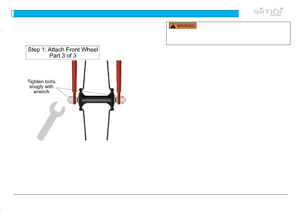
(3) Fasten wheel securely in fork (See Figure
5). Tighten the bolts snugly with a wrench.
Figure 5 – Fasten Wheel Securely in Fork
(4) Test for proper installation. Spin the wheel
to make sure that it is centered in the frame.
Pick up the bike, and sharply hit the top of the
tire with the heel of your hand. The wheel
must not come off, be loose, or move from
side to side.
Failure to properly adjust the quick
release mechanism can cause the wheel to wobble
or disengage. This could cause you to lose control
and fall, resulting in serious injury or death.
Page 14
3 - Assembly: Step 2 - Attach Handlebar
13
C. Step 2 - Attach Handlebar
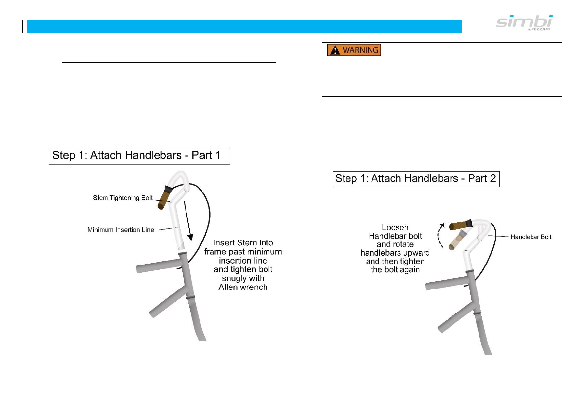
Attach the handlebar and stem to the frame as shown
below.
(1) Insert the Stem into the frame past the
minimum insertion line and then tighten
the bolt snugly with an Allen wrench (See
Figure 6).
Figure 6 – Attach Handlebars to Frame
The stem’s Minimum Insertion Mark
must not be visible above the top of the headset. If
the stem is extended beyond the Minimum
Insertion Mark the stem may break or damage the
frame, and could cause you to lose control and fall.
(2) Loosen the Handlebar Bolt and rotate the
handlebars upward. Then tighten the
Handlebar Bolt again. (See Figure 7).
Figure 7 – Handlebar Adjustment
Page 15
3 - Assembly: Step 2 - Attach Handlebar
14
(3) Test for proper installation.
i. Make sure stem is centered over the front
wheel and bolts are tight.
ii. Make sure Handlebar is aligned properly
and Handlebar Bolts are tightened.
iii. Ensure that the front fork and stem will
turn easily and smoothly from side to side
without your handlebar slipping.
If you do not fully understand any of the
above steps or if you think the handlebar is not
tightened properly, please contact the Simbi
Customer Support Team (see page 32).
An insufficiently tightened stem bolt or
handlebar binder bolt, may compromise steering
action, which could cause you to lose control and
fall. Place the front wheel of the bicycle between
your legs and attempt to twist the handlebar/stem
assembly. If you can twist the stem in relation to
the front wheel, turn the handlebars in relation to
the stem, or turn the bar end extensions in relation
to the handlebar, the bolts are insufficiently
tightened.
Loose or damaged handlebar grips or
extensions can cause you to lose control and fall.
Make sure all wires and cables are free
from obstruction and not wrapped around the stem
or front fork.
Page 16
3 - Assembly: Step 3 - Attach Pedals
15
D. Step 3 - Attach Pedals
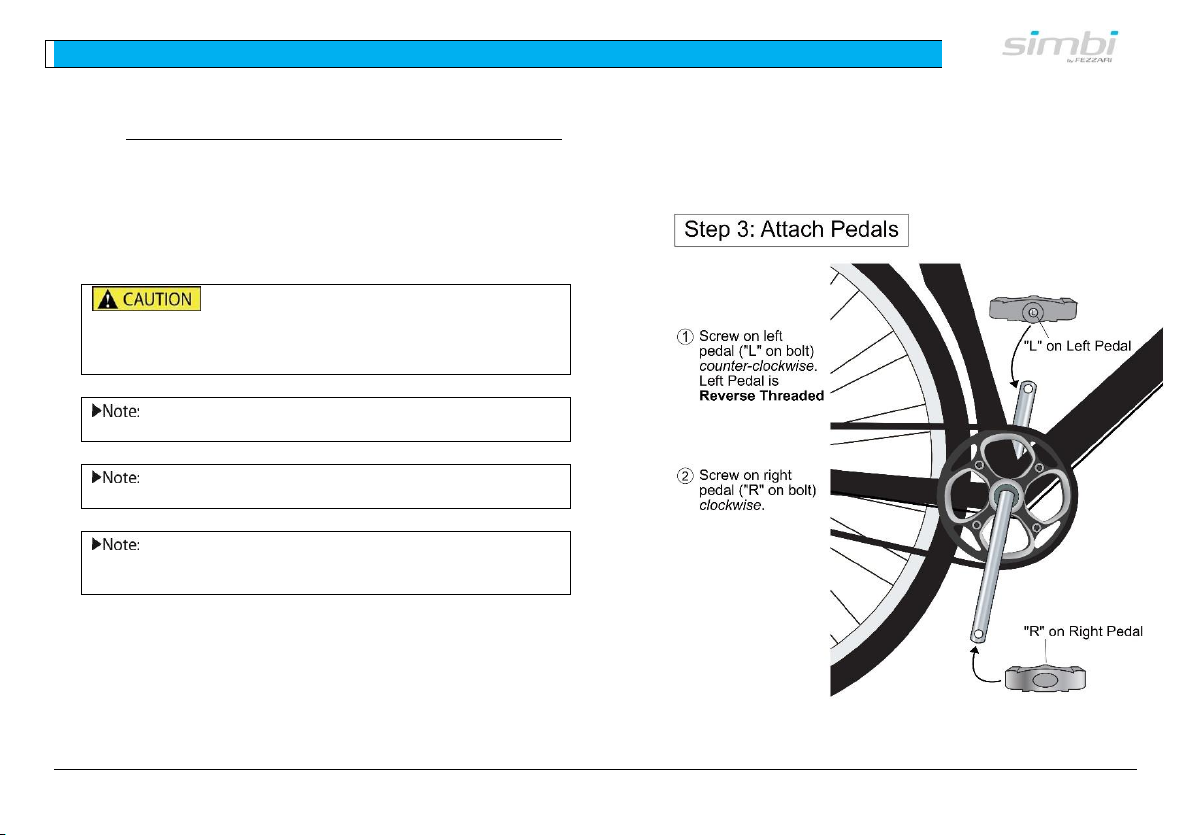
The pedals have different threads based on which
crank arm they should be connected to. The pedals are
marked with “L” for left and “R” for right. Left and
right are determined from the riding position on the
bicycle.
Left and Right Pedals are threaded in
opposite directions. Do not try to force the wrong
pedal onto the crank arm as it will strip the
threading.
Each pedal is marked with “L” for Left of
“R” for Right.
Left and right are relative to riding position
on your bike.
An easy way to remember how to tighten
your pedals is to tighten both pedals towards the
front of your bike.
(1) Align the pedal axle with the threaded hole in
its respective crank arm. Secure the pedal in
the crank by hand. The right pedal is installed
by turning the pedal axle clockwise and the left
pedal is installed by turning the pedal axle
counter-clockwise.
(2) After the pedals can no longer be turned by
hand, use the pedal wrench included in your
tool kit and tighten the pedals securely. The
shoulder of each pedal should fit snugly
against the crank arm.
Figure 8 – Pedal Installation
Page 17
3 - Assembly: Step 3 - Attach Pedals
16
Sometimes noises coming from your
pedals are because you have not sufficiently
tightened the pedal onto the crank. Riding with a
pedal not sufficiently tightened can damage your
crank and pedals and could cause serious injury.
Page 18
3 - Assembly: Step 4 - Inflate Tires
17
E. Step 4 - Inflate Tires
Check the inflation of the tires. Make sure that the
tires are inflated according to the pressure indicated
on the tire sidewall. Tire pressure should not exceed
what is indicated on the sidewall.
Inflate tires only to the pressure
indicated on the tire sidewalls. Do not over-inflate.
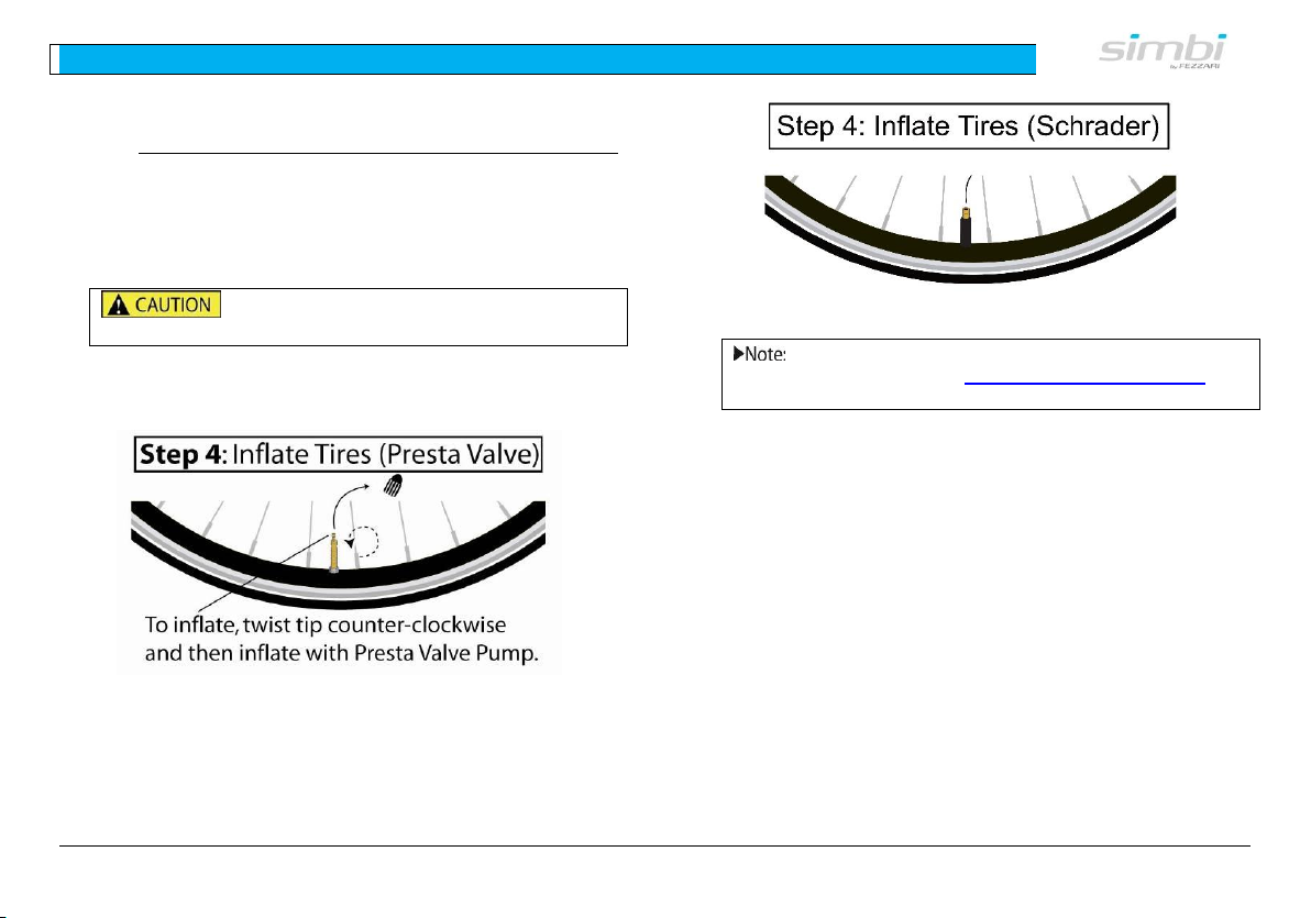
(1) Presta Valve Tire Inflation (See Figure 9).
Figure 9 – Presta Valve Tire Inflation
(2) Schrader Valve Tire Inflation (See Figure
10).
Figure 10 – Schrader Valve Tire Inflation
For best results, use a pump with a built-in
pressure gauge. Check www.SimbiBicycles.com for
high quality pumps and other accessories.
Page 19
3 - Assembly:
Step 6 - Attach Additional Reflectors
18
F. Step 5 - Attach Seat
i. Seatpost Installation
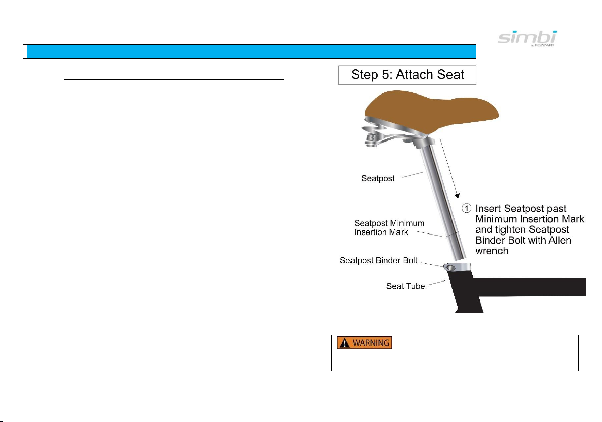
Install the seat post into the seat tube. To adjust the
seat height:
(1) Insert Seatpost into Seat Tube (see Figure
11). Make sure you insert the seatpost past
the Seatpost Minimum Insertion Mark and
Tighten securely.
Figure 11 – Seatpost Installation
Riding with an improperly tightened
seat post can allow the saddle to turn or move and
cause you to lose control and fall.
Page 20
3 - Assembly:
Step 6 - Attach Additional Reflectors
19
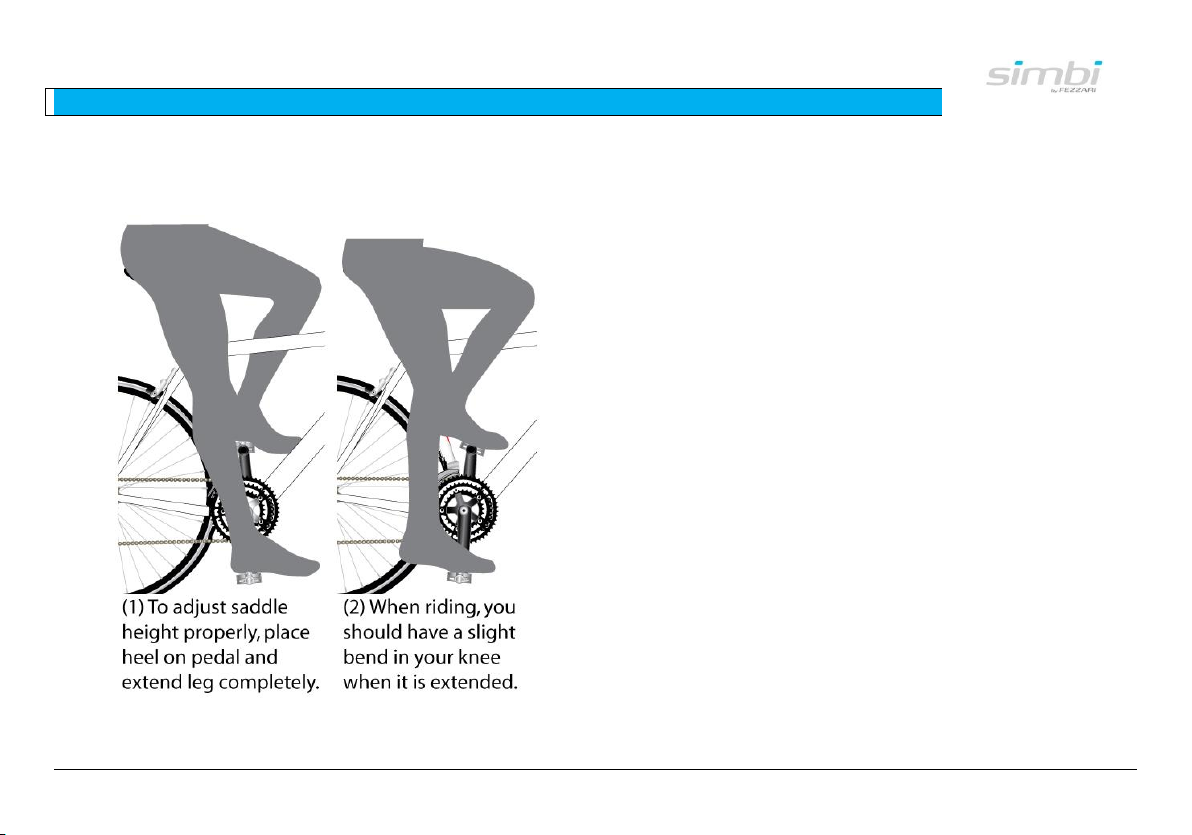
(2) Adjust Seatpost Height (Recommended)
(See Figure 12). Exact saddle height is largely
a matter of personal preference. Below is a
recommended way to adjust seatpost height.
Figure 12 – Recommended Saddle Height
Adjustment
i. Sit on the saddle in riding position without
shoes while someone holds the bicycle
upright.
ii. Position the crank arms so they are
parallel to the seat tube.
iii. Loosen the seatpost binder bolt, or quick-
release.
iv. Place your heel on the pedal and extend
the seatpost until your leg is straight. For
proper riding position, when wearing shoes
and with the ball of your foot on the pedal,
you should have a slight bend in your
knee.
v. Make sure the minimum insertion mark
(See Figure 11) on the seatpost is not
visible above the bike frame. A minimum
of 2 1/2 inches (64 mm) of seatpost must
remain in the frame.
vi. Re-tighten the seatpost quick-release, or
bolt. For a seatpost binder with a quickrelease lever, the mechanism works the
same as a wheel quick-release. Adjust the
lever tension, and make sure it is in the
closed position (see Figure 5 on page 11).
Page 21
3 - Assembly:
Step 6 - Attach Additional Reflectors
20
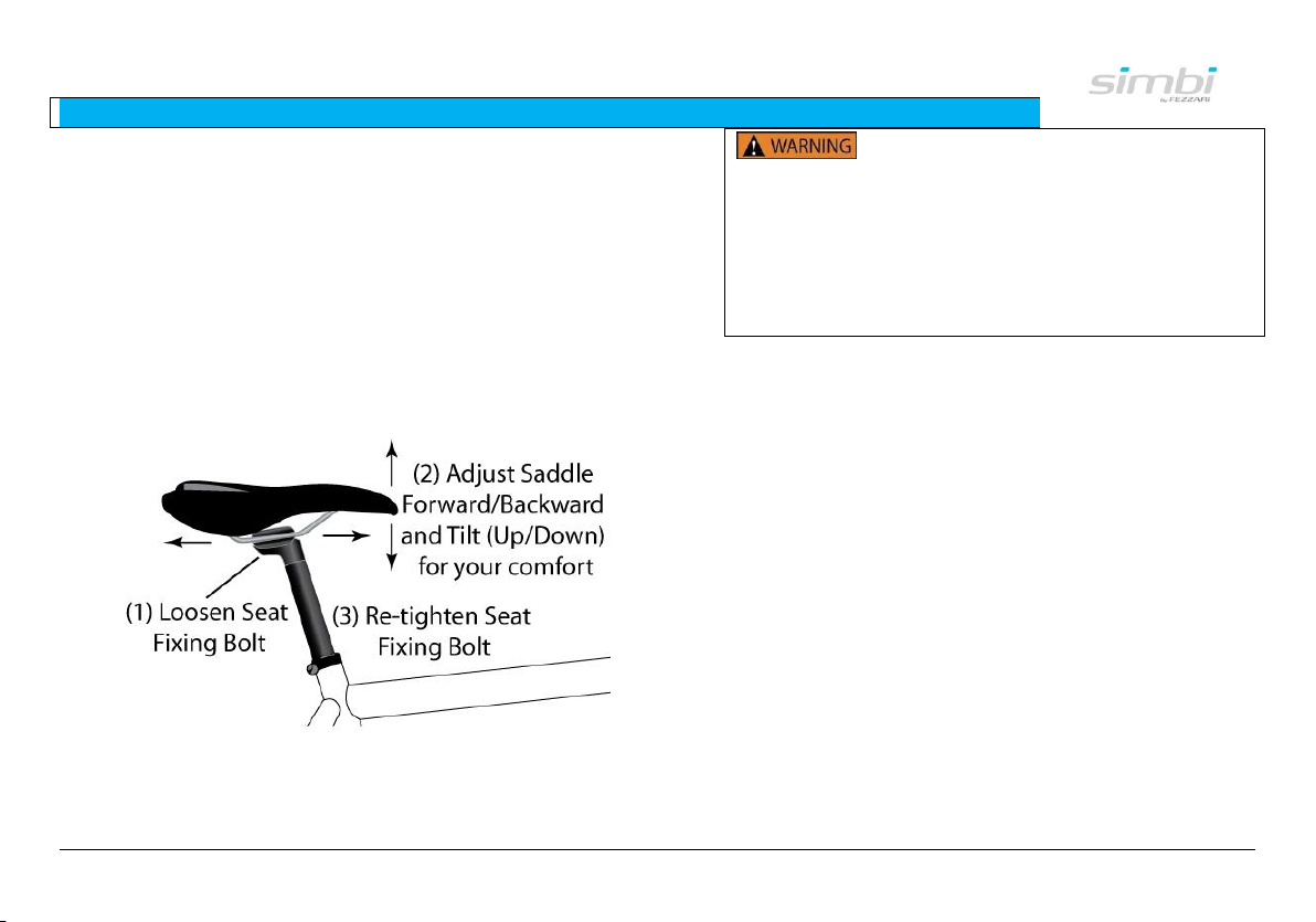
ii. Saddle Adjustment
Seat angle (tilt) and fore-aft positioning is largely a
matter of preference.
(1) Adjust Forward/Backward and Up/Down
Position (See Figure 13). Loosen the Seat
Fixing Bolt and adjust angle and fore-aft
position. Most people prefer a horizontal
saddle. Make sure to tighten completely. When
properly tightened, the seat post cannot be
rotated in the frame.
Figure 13 – Saddle Adjustment
Extended riding with a poorly adjusted
saddle, or one that does not properly support your
pelvic area, can cause short-term or long-term
injury to your nerves and blood vessels. If your
saddle causes pain or numbness, re-adjust the
saddle position. If after adjustment your saddle
still causes pain or numbness, try further
positioning or replacing the saddle with one that
fits you better.
Page 22
3 - Assembly:
Step 6 - Attach Additional Reflectors
21
G. Step 6 - Attach Additional
Reflectors
Additional reflectors are included in the box for
attaching to the handlebar and seatpost. Attach these
to the middle of the front handlebar and on the
seatpost so that they are visible to traffic.
If you ride on public roads, you must
equip your Simbi with the appropriate safety
devices according to the laws of where you are
riding. Consult your local community for bicycle
riding laws, including lights, helmets, reflectors,
where you can and can’t ride, and other rules you
must follow.
Riding bicycles at night or at dusk can
be extremely dangerous. You should ride on
designated, well-lit bike paths. Reflectors alone are
generally not adequate for night-riding. You should
also get a front and rear light. See
www.SimbiBicycles.com for high quality lights and
other accessories.
Page 23
4 - Operation
22
4. OPERATION
A. Before Riding – Important
Safety Information
The information contained in this manual is
to be used as guidelines for safe operation and is
not intended to replace any safety rules or laws
that may be in force in your area.
Make sure all of your quick releases are locked and
secure. Make sure all parts, components, and
accessories are in good working order. Here’s a simple
safety check that you should do every time before you
ride your Simbi:
Frame
□ Inspect – thoroughly inspect frame for
any signs of damage.
Wheels
□ Check bolts on wheels – make sure they
are secure and seated properly.
□ Check Tires & Tubes – make sure they
are inflated according to the pressure
recommended on the tire sidewall. Check
for any wear or tear. Replace damaged
tires before riding. Note: tire pressure can
decrease as much as 5 to 10 psi per week.
Check tire pressure regularly. Ensure that
the valve cap is installed correctly. (See
Figure 9 and Figure 10 on page 16.)
□ Check Rims and Spokes – Inspect for
damage.
Saddle & Seatpost
□ Check Height and Angle – make sure
they are adjusted correctly. (See Figure 12
on page 18, and Figure 13 on page 18, and
the accompanying text.)
□ Check Alignment – make sure the saddle
is parallel to the bike’s center line and
clamped tight enough so that you can’t
twist it out of alignment.
Handlebars
□ Check Alignment – make sure handlebar
stem is parallel to the bike’s center line
and clamped tight enough so that you
can’t twist it out of alignment. (See Figure
6 on page 12.)
□ Check Handlebar Grips – Make sure the
handlebar grips are secure and in good
condition.
Brakes
Page 24
4 - Operation
23
□ Check Braking – check for proper
operation. Squeeze the brake levers. Are
control cables seated and securely
engaged? Do the brake pads contact the
wheel rim squarely and make full contact
with the rim? Do the brake pads touch the
wheel rim within an inch of brake lever
movement? Can you apply full braking
force at the levers without having them
touch the handlebar? If not, your brakes
need adjustment. (See page 23, Brake
Adjustments).
Gears
□ Check Shifting – if gears don’t shift
smoothly or make clicking noises, they
may need to be adjusted. (See page 24,
Gears.) To understand how to shift the
gears on your Simbi better, please see the
supplemental owners manual for the
shifters. For more information, visit
www.SimbiBicycles.com.
Replace any worn or damaged parts before riding
your bicycle. Riding with damaged parts could
cause severed injury or even death.
Always ride with a certified CPSCcertified bicycle helmet. Riding without a helmet
can cause serious injury or death.
Page 25
5 - Maintenance
24
5. MAINTENANCE
Periodically, you may need to adjust some components
on your Simbi for safety and best performance.
A. Inspecting
Check the tightness of key components. Put a wrench
on every important bolt and tighten it slightly to see if
it has loosened:
Check the seat and seatpost bolts
Check the wheel bolts
Check the stem and handlebar bolts
Check the brake and shift lever bolts
Check spoke tension (look for loose spokes)
Tighten pedal screws
Tighten bolts that hold accessories (water
bottle holders)
B. Brake Adjustments
i. Common Brake Adjustments
Over time it is common for cables to stretch. There are
two ways to adjust your brakes.
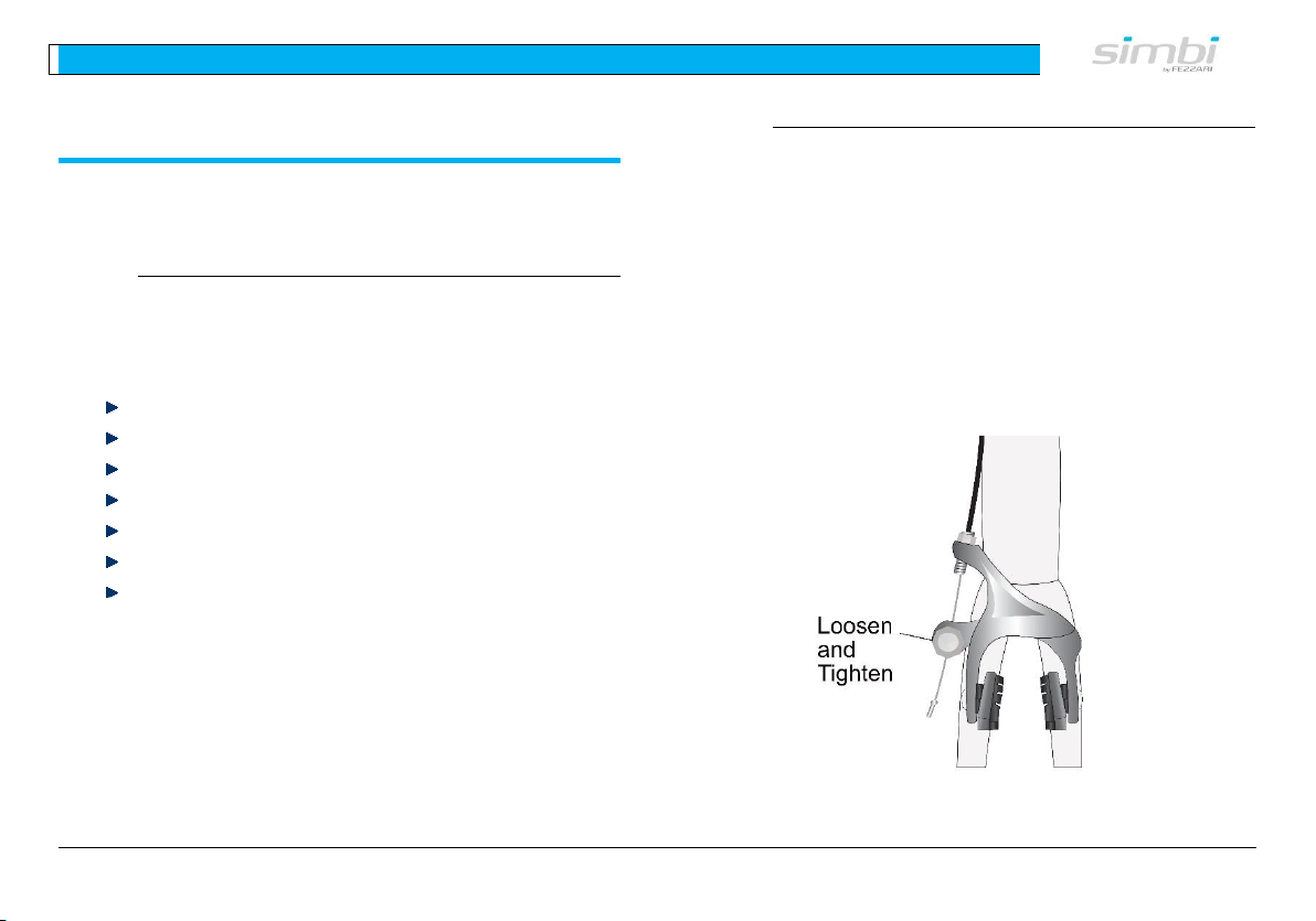
First way: Loosen the bolt shown in Figure 14 and
squeeze the brake pads in towards the rim. Then
tighten the bolt. Test the brakes by spinning the wheel
and applying the hand brake. The brakes shouldn’t be
rubbing on the rim and also should firmly stop the
wheel.
Figure 14 –Brake Adjustments
Page 26
5 - Maintenance
25
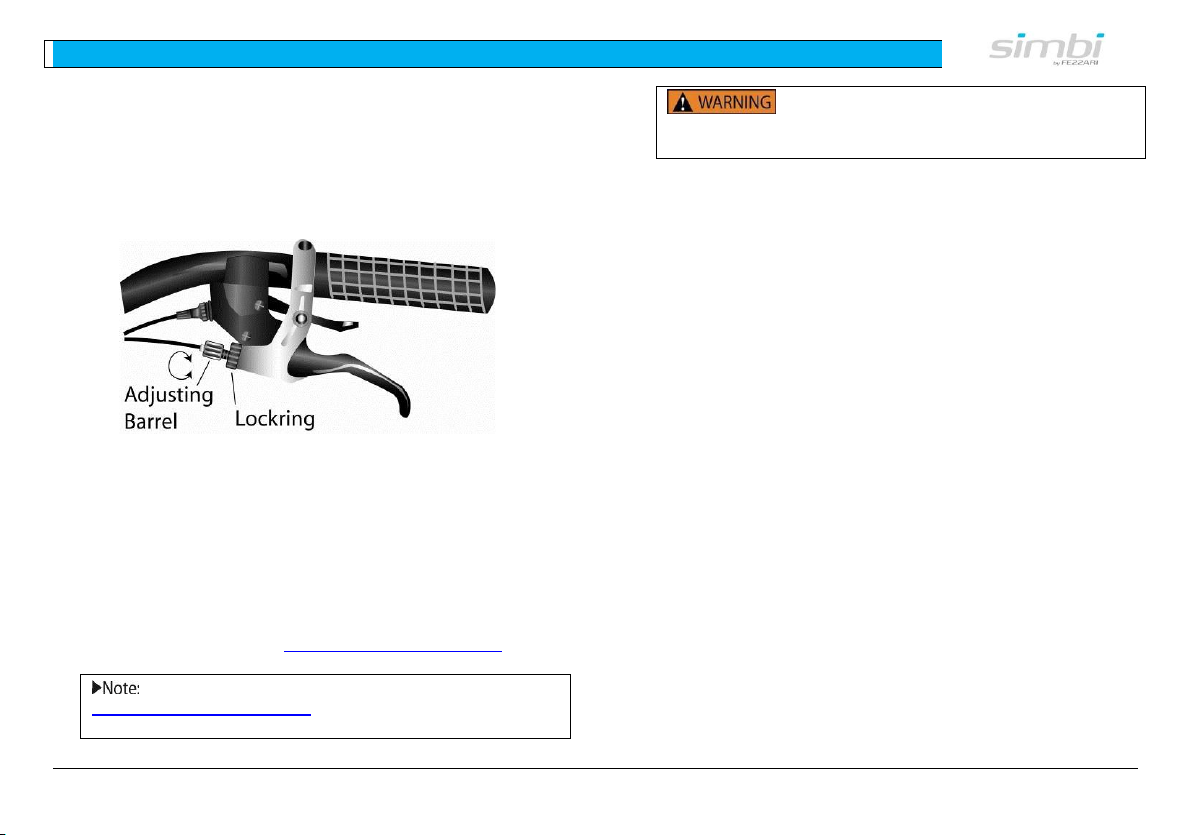
Second way: on some models, there is a barrel
adjustor on the brake lever (see Figure 26). Turn the
adjusting barrel counterclockwise by hand and check
the setting by squeezing the levers.
Figure 15 –Brake Adjustments
When your brakes wear out, the barrel adjuster won’t
work. You’ll need to turn the barrel adjusters all the
way in (clockwise) and replace the brake pads. If the
cable has stretched too far, you need to loosen the
clamp bolt and tighten the cable.
For more information on adjusting and maintaining
your brakes, please visit www.SimbiBicycles.com.
Please contact us at
www.SimbiBicycles.com for more information on
adjusting and maintaining your brakes.
Improperly adjusting your brakes
could cause them to malfunction and could result in
serious injury.
Page 27
5 - Maintenance
26
C. Gears
For gearing For bicycle models equipped with an
internally geared hub (like the Shimano Nexus twist
grip system), please refer to the separate owners
manual for the particular product, and also refer to
www.SimbiBicycles.com.
D. Pedals
Make sure that your pedals are securely fastened to
the cranks. Remember that the left pedal is reversethreaded (counter-clockwise) and the right pedal is
threaded clockwise.
If your pedals develop squeaks, apply lubricant in the
moving parts and wipe off any excess, and make sure
that they are tightened.
Sometimes noises coming from your
pedals are because you have not sufficiently
tightened the pedal onto the crank. Riding with a
pedal not sufficiently tightened can damage your
crank and pedals and could cause injury.
An easy way to remember how to tighten
your pedals is to tighten both pedals towards the
front of your bike.
Page 28
5 - Maintenance
27
E. Wheels
i. Tires & Tubes
All bicycle tires are somewhat porous and allow air to
seep out over time. Low tire pressure makes riding
more difficult, and can damage your rims, tires, and
tubes. Low tire pressure also causes your tires to wear
out quicker. Use a good pump with a built-in gauge
and inflate it to the tire manufacturer’s recommended
pressure, which is located on the sidewall of the tire.
Inflate tires to the tire manufacturer’s
recommended pressure, located on the tire’s
sidewall.
Tire pressure can decrease as much as 5 to
10 psi per week. Check tire pressure regularly.
Ensure that the valve cap is installed correctly.
ii. Spokes and Wheels
Check for loose spokes, which can cause a wheel to go
out of true. To adjust spokes and wheels, take your
bicycle to a certified bicycle mechanic. You can also go
to www.SimbiBicycles.com for more information.
Loose spokes can cause a wheel to go
out of true and collapse, which could cause serious
injury or death.
F. Lubrication
A bicycle has several moving parts that must be
lubricated regularly for optimal performance and to
prevent rust and excessive wear. Use a light bicycle
lubricant. Be careful to wipe off any excess lubricant,
which can attract dirt and dust. You can easily
lubricate the following yourself, and should do it
regularly:
Any Pivots on Brakes (places where parts
move) – apply two to three drops of lubricant
on these places. Make sure to wipe off any
excess.
Pedals – if pedals seem stiff to rotate, or
make noise, apply lubricant in the moving
parts, and wipe off any excess.
Page 29
5 - Maintenance
28
G. Cleaning
Regular and proper cleaning of your Simbi will keep it
looking newer longer, protect the finish, and make it
perform better. If your Simbi gets dirty or muddy (as
in the case of mountain bikes), prop your bike upright
and spray it down with a hose. DO NOT blast water
sideways at the bicycle. This could cause water to get
into the pedals, bottom bracket, or hubs, which could
compromise the bearings, grease, and components
inside. Spray water from above the bicycle, and try not
to spray directly on parts with grease.
You can wash your bike with a bucket of warm water
and mild dishwashing soap. Use a sponge, and for
hard to reach spaces use a soft bristled brush, like a
soft toothbrush. Dry the bike with a soft cloth
afterwards.
Make sure to re-lubricate parts afterwards; otherwise
they may rust if left with water.
You can use any liquid car wax on your Simbi.
H. Storage
Always store your Simbi indoors. The indoor
environment will protect the bike from moisture in
outside air that over time will corrode the metal parts.
It will also protect your Simbi from extended exposure
to sunlight, or salt if you live near an ocean.
One of the easiest ways to store your Simbi is with a
bicycle hook. You can hang it from the front wheel, or
upside down by both wheels. You should not hang your
mountain-bike upside down by both wheels because
this may cause the oil in the front shock to separate.
Hang your bicycle indoors with a bicycle
hook by the front wheel or by both wheels. See
www.SimbiBicycles.com for bike hooks and other
storage accessories.
Do not hang your mountain-bike
upside down by both wheels because this may
cause the oil in the front shock to separate.
Page 30
5 - Maintenance
29
I. Baby your Simbi
Your Simbi was made with high performance
components, and is highly durable. You can ride hard,
but ride smart. Learn to ride with a light technique as
some of the best bikers do and your Simbi’s usable life
will be extended. This will save you time in
maintenance, greatly reduce your chance of injury,
and ensure that your bike will run trouble free much
longer.
Page 31
6 - Simbi Limited Warranty
30
6. SIMBI LIMITED WARRANTY
A. Warranty Information
SIMBI BICYCLE LIMITED LIFETIME WARRANTY
Simbi warrants the frame and rigid fork of each new
Simbi brand bicycle and Simbi brand frameset to be
free from defects in material and workmanship for as
long as the original purchaser owns the bicycle. Paint
finish and all other original components, and all Simbi
brand repair parts, replacement parts, and
accessories, are warranted to be free from defects in
material or workmanship for a period of one year from
the original date of purchase.
LIMITED REMEDY
Unless otherwise provided, the sole remedy under the
above warranty, or any implied warranty, is limited to
the replacement of defective parts with those of equal
or greater value at the sole discretion of Simbi. You
will be responsible for labor costs associated with
warranty replacements. IN NO EVENT SHALL SIMBI BE
RESPONSIBLE FOR DIRECT, INCIDENTAL OR
CONSEQUENTIAL DAMAGES, INCLUDING, WITHOUT
LIMITATION, DAMAGES FOR PERSONAL INJURY,
PROPERTY DAMAGE, OR ECONOMIC LOSSES,
WHETHER BASED ON CONTRACT, WARRANTY,
NEGLIGENCE, PRODUCT LIABILITY, OR ANY OTHER
THEORY.
EXCLUSIONS
THE ABOVE WARRANTY, OR ANY IMPLIED WARRANTY,
DOES NOT COVER NORMAL WEAR AND TEAR. ALL
WARRANTIES ARE VOID IF THE BICYCLE IS MODIFIED
FROM ITS ORIGINAL CONDITION OR THE BICYCLE IS
USED FOR OTHER THAN NORMAL ACTIVITIES,
INCLUDING, BUT NOT LIMITED TO, FAILING TO
FOLLOW THE OWNER’S MANUAL OR USING THE
BICYCLE FOR COMMERCIAL ACTIVITIES OR IN
COMPETITIVE EVENTS, INCLUDING BUT NOT LIMITED
TO BICYCLE RACING, BICYCLE MOTOCROSS RACING,
STUNT RIDING, RAMP JUMPING OR SIMILAR
ACTIVITIES, AND TRAINING FOR SUCH ACTIVITIES OR
EVENTS. SIMBI MAKES NO OTHER WARRANTIES,
EXPRESS OR IMPLIED. ALL IMPLIED WARRANTIES,
INCLUDING THE WARRANTIES OF MERCHANTABILITY
AND FITNESS FOR A PARTICULAR PURPOSE, ARE
LIMITED IN DURATION TO THAT OF THE EXPRESS
WARRANTIES STATED ABOVE.
WHAT YOU SHOULD DO
Contact Simbi Customer Support at
www.SimbiBicycles.com.
Page 32
7- Torque Measurement Tables
31
7. TORQUE MEASUREMENT TABLES
A. Technical Torque Measurements
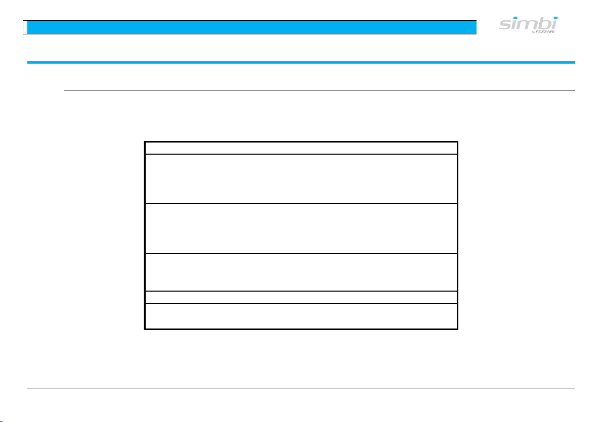
Be careful to follow the directions in this manual and securely tighten each bolt. For reference, the following tables list
recommended torque levels for various components when using a torque wrench:
Table 1 – Maximum Torque Levels for Parts
Component Screw connection Torque (Nm)*
Disk Brake Caliper bolt (fixed to frame or fork) 6
Brake lever clamp screw 4
Disk (rotor) fixation bolt 4
Reservoir cover screw <1
Stem Handlebar clamp screw M5 10-12
Handlebar clamp screw M6 14-16
Cone clamp screw in stem of fork 19
Headset clamp bolts 10-16
Seat post Saddle bolt (two bolt system) 9-11
Saddle bolt (one bolt system) 16-19
Saddle Clamp 12
Bottle Cage Screws 5
*Nm = Newton meters
Page 33
7- Torque Measurement Tables
32
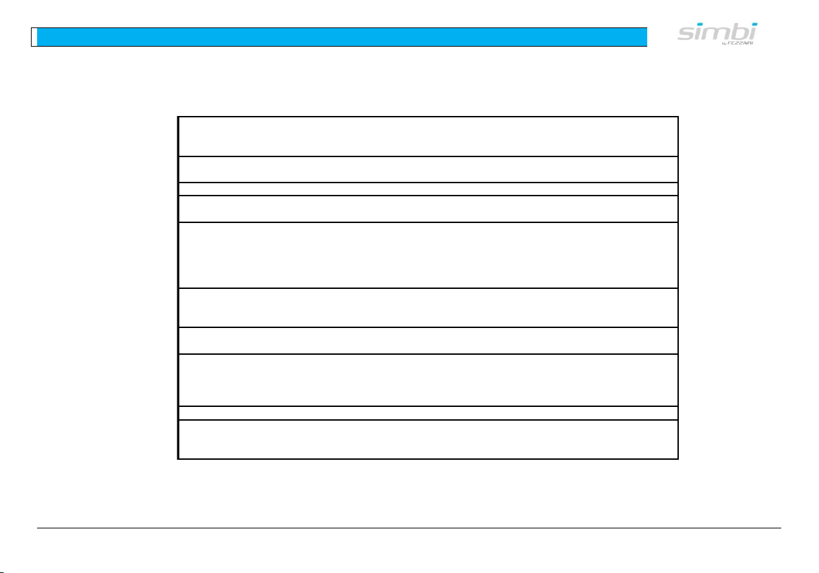
Table 2 - Recommended Torque Levels for Other Screwed Connections
Component Screw Connection Torque (Nm)
35 - 44
35 - 50
8 - 11
35-50
49 - 78
Clipless pedal
axle 10-12
5 - 8
4
Fixing bolt on frame mounting (V-brake) 5 - 9
Pivot bolt Caliper brake 8 - 10
Cable anchor nut 6 - 8
Brake pad fixing bolt 5 - 7
Fastening bolt for cartridge brake pad lining 1 - 2
8 - 10
4 - 6
3 - 4
5 - 7
5 - 7
Mounting bracket bolt (Allen key) 6 - 8
Mounting bracket bolt (screwdriver) 2.5 - 3
Limit stop mounting bolt (frame! (screwdriver) 1 .5 - 2
Shifter fastening bolt 5
Hub
Locknut for adjusting quick-release hub bearing 10 - 25
35 - 49
35 - 44
40
Bottom bracket
Sealed cartridge in housing
Fixed cup (cone) and lock ring
Shoe
Cleat screws
Spike
Rear gear changer
(Rear derailleur)
mounting bolt (hanger bolt)
Cable anchor bolt
Roller cage bolt
Brake
Front gear changer
(Front derailleur)
Mounting bolt
Cable anchor bolt
Freewheel Hub
Freewheel body fixing bolt
Freewheel body fixing nut
Sprocket cluster lock ring
Crankset
Crank fixing bolt (grease-free square-head)
Crank fixing bolt (greased octalink)
chainwheel bolt
Brake- and gear-lever
Page 34

8 - Support
33
8. SUPPORT
A. Simbi Contact Information
For all current contact information, please visit us at www.SimbiBicycles.com.
Questions? Problems?
For Customer Support,
Call (801) 471-0440
Page 35
10 - Table of Figures
34
9. INDEX
Assembly
Box Contents, 5
Barrel adjuster. See Brake
Adjustments and Gear Adjustments
Brakes
Adjustments, 22, 23
Checking Brakes, 22
Campagnolo
Torque Levels, 31
Cleaning, 27
Contact Information, 32
Front Wheel Installation, 10
Gears
Adjustments, 25
Handlebar Installation, 12
Handlebars
Check Alignment, 21
Check Grips, 21
Inspecting, 23
Inspection
Before Riding, 21
Initial, 5
Lubricant, 25, 26
Lubrication, 26
Maintenance, 23
Operation, 21
Pedals, 14, 25
Saddle Adjustment, 19
Safety
Helmets, 22
Reflectors, 20
Safety check, 21
Schrader Valves, 16, See Tire
Inflation
Seatpost Height, 18
Seatpost Installation, 17
Shimano
Torque Levels, 31
Spokes, 26
Storage, 27
Tire Inflation
Road Bike, 16
Schrader Valves, 16
Tires, 26
Inflation, 16
Inspection, 21
Tools, 5, See Assembly
Torque Levels, 30, 31
Tubes, 21, 26
Unpacking, 5
Warranty
Registration, 8
Wheels, 26
Inspection, 21
Page 36
10 - Table of Figures
35
10. TABLE OF FIGURES
Figure 3 - Names and Locations of Parts ............................................................................................................ 6
Figure 5 - Names of Frame Parts ...................................................................................................................... 7
Figure 9 – Loosen Axle Bolts .......................................................................................................................... 10
Figure 10 – Slide Wheel into Fork ................................................................................................................... 10
Figure 11 – Fasten Wheel Securely in Fork....................................................................................................... 11
Figure 12 – Attach Handlebars to Frame .......................................................................................................... 12
Figure 13 – Handlebar Adjustment.................................................................................................................. 12
Figure 19 – Pedal Installation ......................................................................................................................... 14
Figure 20 – Presta Valve Tire Inflation ............................................................................................................. 16
Figure 21 – Schrader Valve Tire Inflation ......................................................................................................... 16
Figure 22 – Seatpost Installation .................................................................................................................... 17
Figure 23 – Recommended Saddle Height Adjustment ....................................................................................... 18
Figure 24 – Saddle Adjustment ...................................................................................................................... 19
Figure 25 –Brake Adjustments ....................................................................................................................... 23
Figure 26 –Brake Adjustments ....................................................................................................................... 24
Page 37
11 - Index of tables
36
11. INDEX OF TABLES
Table 1 – Maximum Torque Levels for Parts ..................................................................................................... 30
Table 2 - Recommended Torque Levels for Other Screwed Connections ............................................................... 31
 Loading...