

Festo Pneumatic VUV Operating Instructions Manual
Bedienungsanleitung
Operating instructions
Instructions de service
Vakuumschaltkopf
TYP
VW
Vacuum control head
Type
VW
Pilote pour vide
Type
VW
P
Anwendung
Application
Mit
dem Vakuumschaltkopf kann ein
Vakuumsignal direkt
in ein Normaldruck-
Signal umgewandelt
werden.
With the vacuum control head a vacuum
signal can be
directly
converted into a normal
pressure signal.
Das
Gerat wird in FESTO
Ventil-Grundkorper
Typ
CJC, CLC, JLC,
LC und
LCO, sowie
anstelle
des Magnetkopfes in
samtliche
Magnetventile
mit
Einschraubgewinde
fvl
20 x 1 eingeschraubt. Zur sicheren
Funk-
tion mu8 der
Dusendurchmesser 15
mm
betragen.
The device is screwed into FESTO basicvalve
bodies, Types
CJC,
CLC,
JLC,
LC and
LCO,
as
well as in place of the solenoid head into all
solenoid valves with screw-in thread M 20 xl.
To ensure reliable operation the nozzle dia-
meter must be
1.5
mm.
Application
Le pilote pour vide
permet
de
convertir direc-
tement un
signal
(vide)>
en un signal
(<pression
normale~~.
L’appareil est
visse
dans
les
de
basedistribu-
teurs
FESTO types
CJC, CLC, JLC,
LC et LCO
ainsi que dans
tous les electrodistributeurs
a
filetageM
20x1
alaplacedupiloteelectrique.
Pour un fonctionnement stir, le diametre de
buse doit etre
de 15 mm.
Montage
Mounting
Montage
Der
Vakuumschaltkopf wird in den
Ventil-
Thevacuum control head isscrewed into the Le pilote pour vide est visse jusqu’en
butee
Grundkorper
bis zum Anschlag
einge-
basic valve body as far as it will go. Screw-in
dans
tous
les de base
distributeurs. Filetage
schraubt.
Einschraubgewinde M 20 x 1.
thread M 20 x I.
M2Oxl.
Funktion
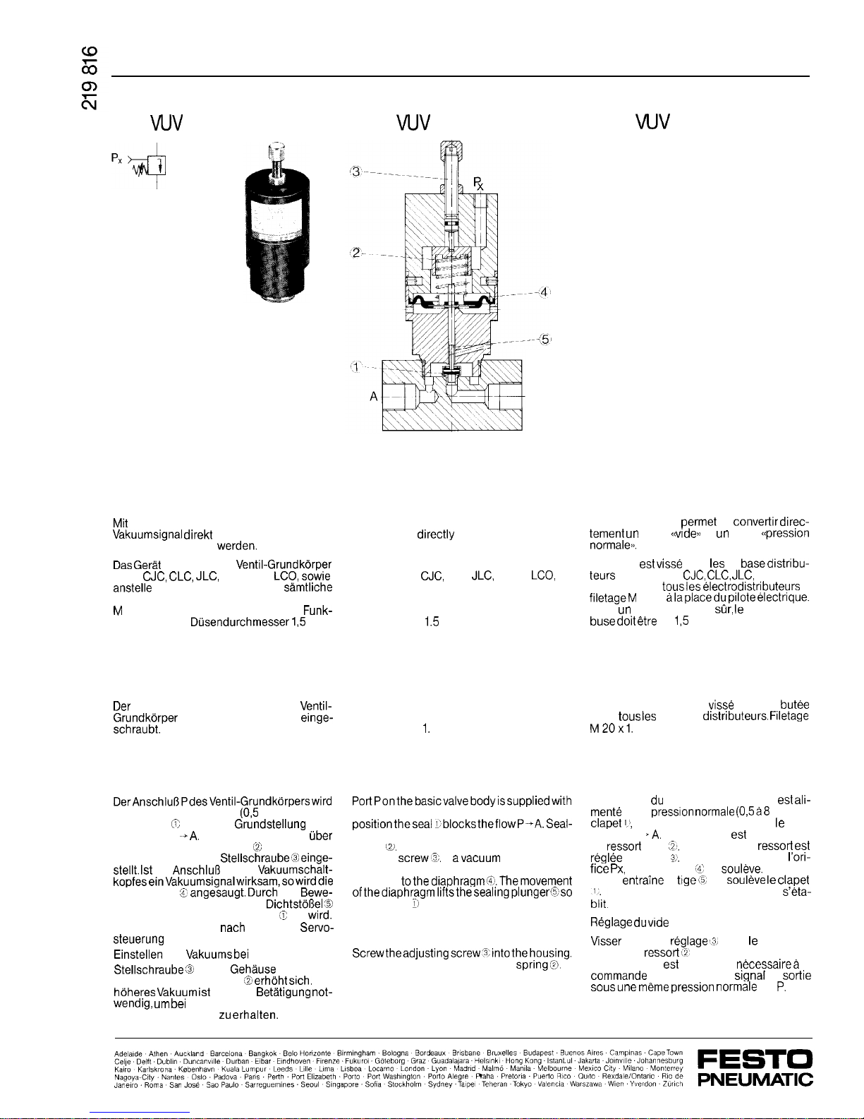
DerAnschl&PdesVentil-Grundkorperswird
mit Normaldruck versorgt
(0,5
bis 8 bar). Der
Dichtsitz R spent in
Grundstellung
den
Durchgang P
+A,
Die Dichtfunktion wird
uber
eine vorgespannte Feder @> erreicht. Die
Federkraft wird an der
Stellschraube@einge-
stellt. 1st
am
Anschlul3
Px des
Vakuumschalt-
kopfeseinVakuumsignalwirksam,sowirddie
Membrane 8
angesaugt. Durch
die
Bewe-
gung der Membrane wird der
Dichtsto8el 3
angehoben, so da8 der Dichtsatz
<II
frei
wird.
Der Durchgang von P
nach
A bzw. die
Servo-
steuerung
wird freigegeben.
Einstellen
des
Vakuums bei
Px:
Stellschraube 3
in das
Gehause
eindrehen.
Die Spannung der Feder
(@II erhoht sich.
Ein
hoheres Vakuum
ist jetzt zur
Betatigung not-
wendig,
urn
bei
gleichem Normaldruck an P
ein Ausgangssignal zu
erhalten.
Function
PortPonthebasicvalvebodyissuppliedwith
standard pressure (0.5 to 8 bar). In its basic
positiontheseal l’blockstheflowP-A.Seal-
ing takes place by means of a pre-tensioned
spring
~\a.
The spring force is adjusted by the
adjusting
screwl\3.
If
avacuum
signal acts on
port Px on the vacuum control head, suction
isapplied
tothediaphragmc%.Themovement
ofthediaphragmliftsthesealingplunger6so
that the seal % becomes free. The flow from P
to A or the servo control is released.
Adjusting the vacuum at Px:
Screwtheadjustingscrew’%intothehousing.
This increases the tension of the
spring@
A
higher vacuum is now required for actuation
in order to obtain an output signal with the
same standard pressure at P.
Fonctionnement
L’orifice P du distributeur de base est
ali-
mente
par la
pression normale (05a8
bar). Le
clapet
11,
en position de repos ferme le pas-
sage de P
‘A.
La fermeture est obtenue par
un
ressort
tare
,?b.
La tension du
ressort
est
@glee par la vis
2,.
En presence devidea
l’ori-
fice Px,
la membrane Y se
soul&e.
La mem-
brane
entraine
la
tige<st
qui
soul&e
le
clapet
biit.
Le passage entre P et A
s’eta-
Reglage du vrde
en Px:
Visser
la vis de
reglage ‘3)
dans le corps. La
tension du
ressot-t (2’
augmente. Une depres-
sion plus forte est maintenant
necessairea
la
commande
pour recevoir un
signal
de
sonie
sous une meme pression normale
en
P.
Technische Daten
Medium
gefilterte, nicht
geolte Druckluft
Befestigungsart
Gewinde M 20 x 1
Anschlu6
Px
M5
BetriebsdruckJerejch (Ventil-
Grundkorper)
+0,5
bis 8 bar
Vakuumbereich Px
-0,2
bis
-0,95
bar
max.
zulassiger
Druck
Px
+0,5
bar
Schalthysterese
max. 0,2 bar
Temperaturbereich -10 bis
+60°
C
Werkstoffe Al, MS, Dichtungen:
Perbunan
Gewicht
0,180 kg
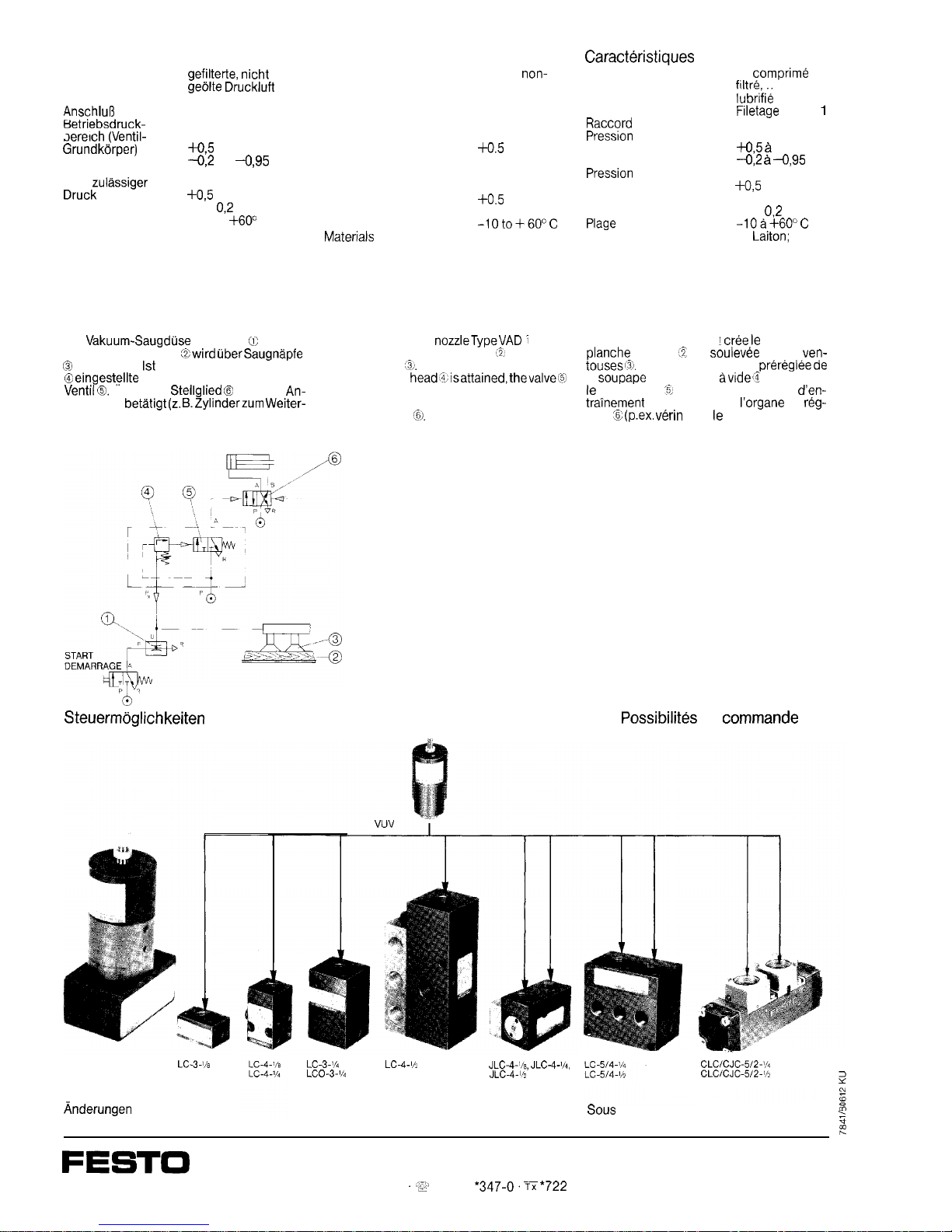
Anwendungsbeispiel
Application example
Die
Vakuum-Saugduse
Typ VAD K erzeugt
Vakuum. Ein Holzbrett
Zwird tibersaugnapfe
0)
angehoben.
1st
das am Vakuumschaltkopf
@ eingestellte
Vakuum erreicht, schaltet das
Ventil @.
Uber das
Stellglied @
wird ein
An-
triebsglied
betatigt (z. B.Zylinderzum Weiter-
transport).
Thevacuumsuction
nozzleTypeVAD
7
generates vacuum. A wooden board m& is lifted via
suction cups
<&.
If the vacuum set on the
vacuumcontrol
head~%isattained,thevalve~%
switches. A driven member (e.g. cylinder for
further conveying) is actuated via the final
control element
@.
Technical Data
Medium
Mounting
Connection Px
Operating pressure range
(basic valve body)
Vacuum range Px
Max. permissible
pressure Px
Switching hysteresis
Temperature range
Materials
Weight
filtered,
non-
lubricated
compressed air
thread M 20 x 1
M5
+0.5
to 8 bar
-0.2 to -0.95 bar
+0.5
bar
max. 0.2 bar
-10to+60°C
Al, brass; seals:
Perbunan
0.180 kg
g
SteuermOglichkeiten
Possible control applications
Caract&istiques
techniques
Fluide Air
comprime
filtre
non
lubrifie
Fixation
Filetage
M 20 x I
Raccord
Px M5
Pression
de service
(de base distributeur)
+0,5 a
8 bar
Plage de depression Px
--0,2 & -0,95
bar
Pression
max.
admissible Px
+0,5
bar
Hysteresis de
commutation max. 0,2 bar
Plage
de temperature
-lOa+6O”C
Materiaux Al,
Laiton;
joints:
Perbunan
Poids
0,180 kg
Exemple d’application
Le venturi type VAD !
tree le
vide. Une
planche
de bois ‘Z est
soulevee
par les
ven-
touses$.
Lorsqueladepression
preregleede
la
soupape
de sequence
avideX
est atteinte,
le distributeur
‘5)
commute. Un organe
d’en-
tramement
est actionne par
l’organe
de
reg-
lage % (p.ex.
v&in
pour le transport).
LC-3%
Anderungen
vorbehalten
LC-3.‘/d
LC-4-lh
JLC-4.‘la, JLC-4-‘h,
LCO-3.‘14
JLC-4-lh
The right to modifikation is reserved
Possibilit&
de
commande
CLC/CJC-512-~h
CLClCJC-512-~/s
I
?
Sous
reserve de toutes modifications
Z
:
?
PNEUMATIC
Postfach 6040 D-7300 Esslingen 1
.:i
(07 11)
*347-0.
TYC
*722
727-0
 Loading...