

Festo Pneumatic SFL-6 Operating Instructions Manual
Bedienungsanleitung Operating instructions Notice d’emploi
Gabelluftschranke
Anwendung Application
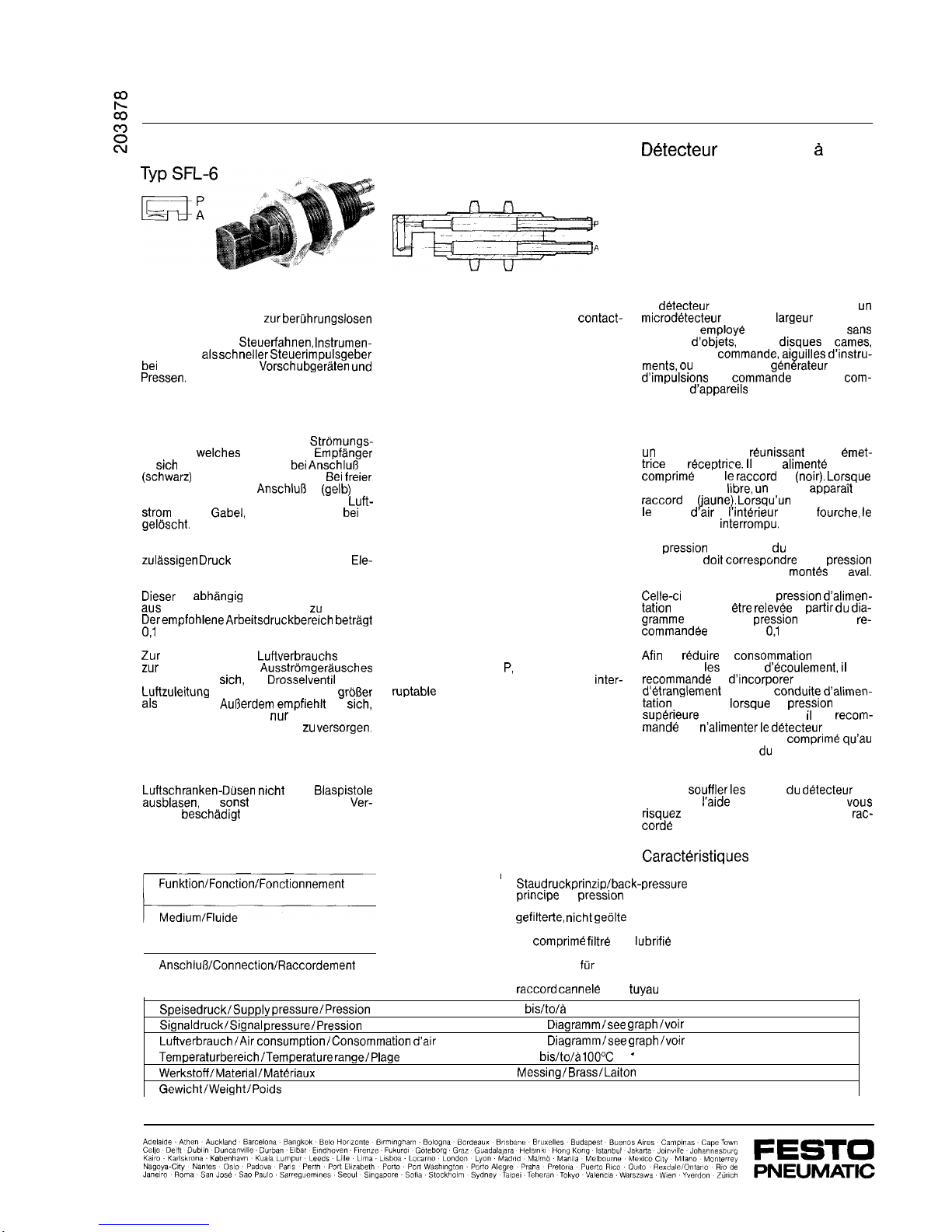
Die Gabelluftschranke ist ein Micro-Sensor
mit 6 mm Gabelbreite
zur beruhrungslosen
Abtastung
von
Gegenstanden,
z. B. von
Nockenscheiben,
Steuerfahnen, lnstrumen-
tenzeigern,
als schneller Steuerimpulsgeber
bei
Steuerungen von
Vorschubgeraten und
Pressen
The interruptablejet sensorisamicro-sensor
with clearance width of 6 mm for
contact-
less sensing of objects, e.g. cam discs,
control tabs, instrument pointers, and as a
rapid pulse generator for the control of feed
units and presses.
Funktion
Die Gabelluftschranke ist ein
Stromungs-
element,
welches
Sender und
Empfanger
in
sich
vereinigt. Sie wird
bei Anschlu8
P
(schwarz)
mit Druckluft versorgt.
Bei freier
Gabel erscheint am
Anschlul3
X
(gelb)
ein
Signal. Unterbricht ein Gegenstand den
Luft-
Strom
in der
Gabel,
wird das Signal bei X
geloscht.
Der Signaldruck der Luftschranke mu8 dem
zulassigen Druck
der nachgeschalteten Ele-
mente entsprechen.
Dieser
ist
abhangig
vom Speisedruck P und
aus
nachfolgendem Diagramm zu ersehen.
DerempfohleneArbeitsdruckbereich betragt
0,l
bis 2 bar.
Zur
Verringerung des
Luftverbrauchs
sowie
zur
Verminderung des
Ausstromgerausches
empfiehlt es
sich,
ein
Drosselventil
in die
Luftzuleitung
P einzubauen, wenn P
gro8er
als 3 bar ist.
Au8erdem empfiehit
es
sich,
die Gabelluftschranke
nur
im Augenblick
der Signalgabe mit Druckluft zu
versorgen.
Achtung!
Luftschranken-Dusen nicht
mit
Blaspistole
ausblasen,
da
sonst
angeschlossene Ver-
starker
beschadigt
werden konnen!
Technische Daten
Funktion/Fonction/Fonctionnement
Anschlu8/Connection/Fiaccordement
Interruptable jet sensor
Type SFL-6
Operation
The interruptable jet sensor is a flow element
in which emitter and receiver are combined.
It is supplied via port P (black) with compressed air. When not obstructed a signal
is generated at port X (yellow). Should an
object interrupt the flow of air the signal
at X is cancelled.
The signal pressure of the interruptable jet
sensor must correspond to the allowable
pressure of the downstream components,
This pressure is dependent on the supply
pressure P and can be read off from the
graph below. The recommended working
pressure range is 0.1 to 2 bar.
To reduce air consumption and operating
noise it is advisable to install a throttle valve
in the air supply line
P,
if P exceeds 3 bar.
Furthermore it is recommended that the
inter-
ruptabie
jet sensor be supplied with compressed air only at the times when a signal
is given.
Caution!
Do not blow out interruptable jet sensors
with an air gun, otherwise connected amplifiers could be damaged.
Technical data
,
Detecteur
de passage
a
fourche
Type SFL-6
Application
Le
detecteur
de passage a fourche est
un
microdetecteur
ayant une
largeur
de fourche
de 6 mm,
employe
pour la detection
saris
contacts
d’objets,
par ex.
disques
a
tames,
talons de
commande, aiguilles d’instru-
merits,
ou en tant que
generateur
rapide
d’impulsions
de
commande
pour la
com-
mande
d’appareils
de translation et de
presses.
Fonctionnement
Le detecteur de passage a fourche est
un
element fluidique
reunissant
buses
emet-
trite
et
receptrice. II
est
alimente
en air
cornprime
par le
raccord
P (noir).
Lorsque
la fourche est
libre, un
signal
apparaTt
au
raccord
X
(jaune). Lorsqu’un
object coupe
le debit
d’air
a
i’interieur
de la
fourche,
le
signal en X est
interrompu.
La
pression
de signal du detecteur de
passage
doit correspondre
a la
pression
admissible des elements
mantes
en
aval.
Celle-ci
depend de la
pression d’alimen-
tation
P et peut
etre relevee
a
partir du dia-
gramme
suivant. La
pression
de travail re-
commandee
varie entre
0,l
et 2 bar.
Afin de
reduire
la
consommation
d’air et de
diminuer
les
bruits
d’ecoulement, il
est
recommande
d’incorporer
une
valve
d’etranglement
dans la
conduite d’alimen-
tation
en air P
lorsque
la
pression
P est
superieure
a 3 bar. En outre, il est
recom-
mande
de
n’alimenter le detecteur
de pas-
sage a fourche en air
cornprime qu’au
moment de remission du signal
Attention!
Ne pas
souffler les
buses du
detecteur
de
passage a
l’aide
d’un pistolet a air car
vous
risquez
d’endommager l’amplificateur
rac-
corde
par une trop forte pression!
Caractbistiques
techniques
Staudruckprinzip/back-pressure
principle/
principe
de
pression
dynamique
gefilterte, nicht geolte
Druckluft
filtered, non-lubricated compressed air
air
cornprime filtre
non
lubrifie
Stecknippel
fur
Kunststoffschlauch NW 3
serrated nipple for plastic tubing NW 3
raccord cannele
pour
tuyau
plastique DN 3
Speisedruck/Supply pressure/Pression
d’alimentation
P
Signaldruck/Signal pressure/Pression
de signal
X
Luftverbrauch/Air consumption/Consommation d’air
Temperaturbereich/Temperature range/Plage
de temperature
Werkstoff/Material/Materiaux
GewichtlWeightlPoids
0
bislto/a
8 bar
siehe
Diagramm/see graph/voir
diagramme
siehe
Diagrammlsee graph/voir
diagramme
-40
his/to/a 100%
.
Messing/BrassfLaiton
0,033 kg
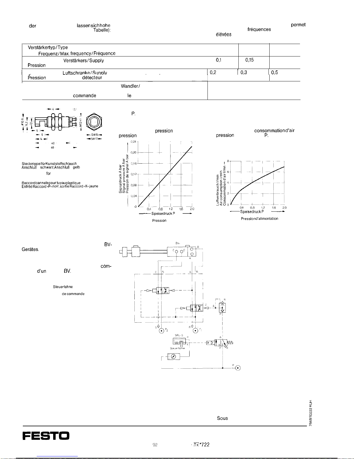
Mit
der
Gabeliuftschranke
iassen sich hohe
High switching frequencies can be attained
Le detecteur de passage a fourche
permet
Schaltfrequenzen erzielen (siehe
Tabelle):
with the interruptable jet sensor (see table):
d’atteindre des
frequences
de commutation
elevees
(voir tableau):
Verstarkertyp/Type
of amplifier/Type d’amplificateur
Max,
Frequenz/Max. frequency/Frequence
max.
Speisedruck des
Verstarkers/Supply
pressure to amplifier/
Pression
d’alimentation de l’amplificateur
PE-VK-5
28 Hz
0,i bar
PE-VK-100
35 Hz
0,15
bar
PE-1000
100 Hz
1
Soeisedruck der
Luftschranke/Suoplv
pressure to interruptable jet sensor/
1
0,2
bar 1 0,3 bar 1 0,5 bar 1
*-
Pression
d’alimentation du
detect&r
de passage
Lange der Steuerleitung zwischen SFL-6 und
Wandlerf
Length of control line between SFL-6 and converter/
Longueur du canal de
commande
entre SFL-6 et le convertisseur
50 cm
Stecknippel
fur
Kunststoffschlauch
NW3
Anschlufi
P
schwarz, AnschluI3
A
gelb
Serrated nipple
for
plastic tubing NW 3
Input port P black, output port X yellow
Raccord cannele pourtuyau plastique
DN 3
Entree Raccord G~P,s noir, sotiie Raccord ~~Xra)aune
Schaltplanbeispiel zur Steuerung eines
BV-
Gerates.
Circuit example for the control of a strip
feed unit.
Exemple de schema de circuit pour la
com-
mande
dun
appareil
BV.
Steuerfahne
Control tab
Talon
decommande
Signaldruck A in Abhangigkeit vom Speise-
Luftverbrauch in Abhangigkeit vom Speise-
druck
P.
druck P.
Signal pressure A as a function of supply
pressure P.
Relation entre la
pression
de signal A et la
pression
d’alimentation P.
Air consumption as a function of supply
pressure P.
Relation entre la
consommation d’air
et la
pression
d’alimentation
P.
”
0,4
o,*
12
I,6
20
~ SpeisedruckP
bar
-
Supply pressure P bar
Press~on
d’alimentation P bar
~ SpeisedruckP
bar
M
Supply pressure P bar
Pression d’al~mentatlon
P bar
Anderungen vorbehalten The right to modification is reserved
Sous
reserve de toutes modifications
?
%
e
FESTO
PNEUMATIC
Postfach 6040 D-7300 Esslingen 1 ‘@ (07 11) l 347-0
‘33
*722
727-0
 Loading...