

Festo Pneumatic IC-8M 3/2-2.0-24 TH, IC-8M 3/2-2.0-24 PH Operating Instructions Manual

Operating instructions
Interface card
242 498
Bedienungsanleitung
Interface-card
Type
IC-8M 3/2-2.0-24
PH
Order code
14
021
IC-8M
3/2-2.0-24
THOrder code14 022
Conditions regarding use of this equipment?
1.
This equipment should only be used
within
the limits
detailed in the technical specification. Strict
observa-
tionofthe technicalspecificahonshould
be ensured at
all times.
2.
Correctly prepared compressed air should be used at
all times. When
installina
the
eauroment
and thereafter
the Customer shall
ensirethatthe
environmental con-
ditionsatthe
placeof useare
taken
intoconsideration.
3.If incorporated in a system or used within safety
devices or circuits the Customer shall ensure that
national and local safety laws and regulations are
observed.
4. Should you require further information please contact
your local Festo office.
Was ist berm
Ernsatz van
Festo Elementen zu beachten?
Die
Ernhaltung der jeweils angegebenen Grenzwerte
fur
Dnicke Spannungen, Temperaturen und
die Beachtung
van Hinweisen
ist
Voraussetzung
fur die
ordnungsge-
mage Funktion und dahervom Anwender unbedingt
au
gewahrleisten.
Es
1st
auf den
Betrreb
mit
ordnungsgemaf3 aufbererteter
Druckluff ohne
aggressive
Medren zu achten. Auflerdem
sind die
jewerlrgen Umweltbedrngungen
am
Einsatzort
au
berticksichtigen.
Bei
Anwendung van
Festo
Elementen
im
Sicherheitsbe-
reich
sind
stets such
die
jeweikgen Vorschnften der
Be-
rufsgenossenschaft und
des
Technrschen Uber-
wachungsvereins bzw.
die
entsprechenden natronalen
Bestimmungen
au
berucksichtigen
1.
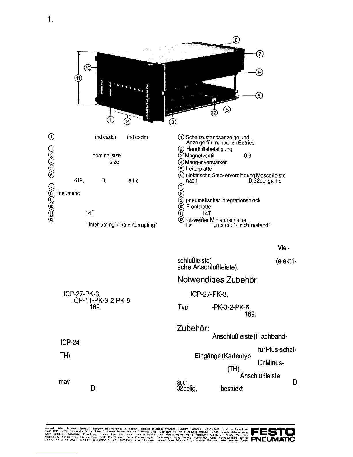
Constructional principle of the
Interface card
1. Aufbauprinzip der Interface-card
@
Switching status
indicador
and
mdbcador
for manual operation
@I
Manual override
@
Solenoid valve,
nommai
SIX 0.9
@
Flow amplifier, nominal SW 2
@
Printed circuit board
@
Electrical plug connection, terminal strip
DIN 41
612,
design D, 32 poles
a+c
@
Barbed fittings
@ Pneumatic
multi-tube connector
@
Pneumatic integrated block
@I
Front plate
@
Modular grid
14T
@
Red-white miniature switch
for MAN ON,
“interruptmg”/“non interruptI@’
@ Schaltzustandsanzeige und
Anzelge ftir manuellen Betrieb
@ HandhilfsbetCttigung
@ Magnetventil
Nennweite
0,9
@ Mengenverstarker
Nennweite 2
@ LeiterplaHe
@ elektrische Steckerverbindung Messerlelste
nach
DIN 41 612, Bauform D,
32polig a+c
@
Stecknippel
@
pneumatische Vielfachsteckkupplung
@ pneumatischer Integrationsblock
@ FrontplaHe
@
Raster
14T
@ rot-wei6er Mimaturschalter
ftir
MAN ON
,,rastend”/,,nicht rastend“
Scope of delivery:
Lieferumfang:
Interface card without pneumatic multi tube
connector (pneumatic manifold) and
Interface-card ohne pneumatische
Viel-
without multi pole strip (electrical terminal
fachsteckkupplung (pneumatische An-’
strip).
schlu6leiste)
und ohne Federleiste
(elektri-
sche Anschlul3leiste).
Accessories required:
Pneumatic multi tube connector
Type
ICP-27-PK-3,
order code 15 166
or Type
ICP-11-PK-3-2-PK-6,
order code 15
169.
Notwendiges Zubehdr:
pneumatische Vielfachsteckkupplung
Typ
ICP-27-PK-3,
Bestellbezeichnung 15 166 oder
Tvp
ICP-11
-PK-3-2-PK-6,
Bestellbezeichnung 15
169.
Other accessories:
Electrical terminal strip (flat cable adaptor),
type
ICP-24
P-FLK, order code 15 174 for
positive switching inputs (card types PH
and
TH);
order code 15 175 for negative switching
card (TH).
Instead of the electrical terminal strip,
one
may
also use a multi pole socket to DIN
41 612, design D, 32 poles, a und c fitted.
Standard parts required:
Rack: Schroff company, Europac Rational.
Zubehdr:
Elektrische
Anschlu6leiste (Flachband-
kabeladapter) Typ ICP-24 P-FLK
Bestellbezeichnung 15 174
fur Plus-schal-
tende
Eingange (Kartentyp
PH und TH);
Bestellbezeichnung 15 175
fur Minus-
schaltende Karte
(TH).
Statt der elektrischen
Anschlul3leiste
kann
such
eine Federleiste DIN 41 612 Bauform
D,
32poiig,
a und c
bestuckt
verwendet werden.
Notwendige Normteile:
Baugruppentrager Fa. Schroff,
Europac Rational.
 Loading...