

Page 1
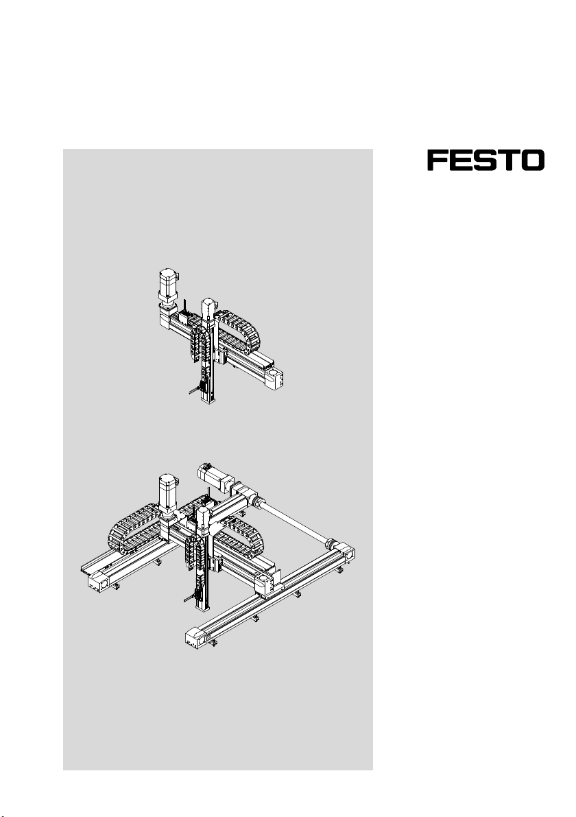
Handling system
YXC...
Description
Mechanical
installation
8030870
1502NH
[8030863]
Page 2
YXC...
Translation of the original instructions
GDCP-YXC-EN
Identification of hazards and instructions on how to prevent them:
Danger
Immediate dangers which can lead to death or serious injuries.
Warning
Hazards that can cause death or serious injuries.
Caution
Hazards that can cause minor injuries or serious material damage.
Other symbols:
Note
Material damage or loss of function.
Recommendations, tips, references to other documentation.
Essential or useful accessories.
Information on environmentally sound usage.
Text designations:
Activities that may be carried out in any order.
1. Activities that should be carried out in the order stated.
– General lists.
è Result of an action/References to more detailed information.
2 Festo – GDCP-YXC-EN – 1502NH – English
Page 3

YXC...
Table of Contents – YXC...
1 Safety and requirements for product use 6......................................
1.1 Technical data 6............................................................
1.1.1 Ordered strokes [mm] 6.............................................
1.2 Safety 7..................................................................
1.2.1 General safety information 7..........................................
1.3 Intended use 7.............................................................
1.3.1 Possible misuse 7..................................................
1.4 Permitted mounting position 8................................................
1.5 Requirements for product use 8...............................................
1.5.1 Obligations of the operating company 9.................................
1.5.2 Qualified specialized personnel 9......................................
1.5.3 Range of application and certifications 9................................
2 Conveying and storage 10.....................................................
2.1 Conveying 10...............................................................
2.2 Storage conditions 10........................................................
2.3 Unpacking 10...............................................................
2.4 Transport protection aids 11...................................................
2.4.1 Securing in the transport protection crate 11.............................
2.4.2 Securing when lifting 11..............................................
2.4.3 Securing during transport and mounting 16...............................
3 Overview 18................................................................
3.1 Delivery status 18...........................................................
3.1.1 Completely mounted handling system 18.................................
3.1.2 Partially mounted handling system 18...................................
3.2 Module types 18............................................................
3.2.1 X-module EHMX (including motor) 18....................................
3.2.2 Y-module EHMY (including motor) 21....................................
3.2.3 Z-module EHMZ (including motor)/DHMZ 23..............................
3.3 Handling systems 25.........................................................
3.3.1 Single-axis system YXCS 25...........................................
3.3.2 Linear gantry YXCL 26................................................
3.3.3 Planar surface gantry YXCF 27..........................................
3.3.4 Three-dimensional gantry YXCR 28......................................
3.4 Handling systems without motors 29............................................
Festo – GDCP-YXC-EN – 1502NH – English 3
Page 4

YXC...
4 Installation of the single-axis systems and the linear gantries 30....................
4.1 Preparation 30..............................................................
4.1.1 Installation space 30.................................................
4.1.2 Number n of mounting components 30..................................
4.1.3 Preparation of the mounting surface 31..................................
4.2 Mounting components 32.....................................................
4.2.1 Mounting kit with adjustment possibility 32...............................
4.3 Installation of single-axis system and linear gantry 37...............................
4.3.1 Installation YXCS/YXCL 37.............................................
5 Installation of the planar surface gantries and the three-dimensional gantries 39.......
5.1 Preparation 39..............................................................
5.1.1 Installation space 39.................................................
5.1.2 Number n of mounting components 39..................................
5.1.3 Preparation of the mounting surface 40..................................
5.2 Mounting components 44.....................................................
5.2.1 Mounting kit without adjustment possibility 44............................
5.2.2 Adjusting kit 47.....................................................
5.3 Completely mounted handling system 51.........................................
5.3.1 Installation YXCF/YXCR 51.............................................
5.4 Check the alignment and structure 57............................................
5.5 Connecting shaft 58..........................................................
5.5.1 Structure 58.......................................................
5.5.2 Mounting of the connecting shaft 58....................................
5.6 Motor with brake (EMMS-...-RSB/RMB) 67........................................
5.6.1 Dismantling 67.....................................................
5.6.2 Mounting 67.......................................................
6 Attachment components 68...................................................
6.1 Mounting to the Y-module 68..................................................
6.2 Mounting to the Z-module 68..................................................
7 Installation 69..............................................................
7.1 Safety instructions 69........................................................
7.2 Earthing 71.................................................................
7.2.1 Earthing points 71...................................................
7.2.2 Earthing points at the single-axis system 72..............................
7.2.3 Earthing points at the linear gantry 73...................................
7.2.4 Earthing points at the planar surface gantry 74............................
7.2.5 Earthing points at the three-dimensional gantry 75.........................
4 Festo – GDCP-YXC-EN – 1502NH – English
Page 5

YXC...
7.3 Cables and hoses 76.........................................................
7.3.1 Completely mounted handling system 76.................................
7.3.2 Cables 76..........................................................
7.3.3 Hoses 76..........................................................
7.3.4 Energy chain subdivision Z-modules 77..................................
7.3.5 Energy chain subdivision Y-modules 78..................................
7.3.6 Energy chain subdivision X-modules 80..................................
7.3.7 Installation 80......................................................
7.3.8 Checking the energy chain 81..........................................
8 Commissioning 82...........................................................
8.1 Safety instructions 82........................................................
8.2 Proximity sensors 84.........................................................
8.3 Test run 84.................................................................
9 Operation 85...............................................................
9.1 Safety instructions 85........................................................
9.2 Characteristic curve of the connecting shaft 85....................................
10 Maintenance and care 86.....................................................
10.1 Safety instructions 86........................................................
10.2 Cleaning 87.................................................................
10.3 Lubrication 87..............................................................
11 De-commissioning, dismantling, disposal 88.....................................
11.1 Safety instructions 88........................................................
11.1.1 General 88.........................................................
11.1.2 Dismantling 88.....................................................
11.1.3 Disposal 88........................................................
12 Fault clearance 89...........................................................
12.1 Malfunctions and remedy 89...................................................
12.2 Repair 90..................................................................
A Technical appendix 91........................................................
A.1 Technical data 91............................................................
A.1.1 Certifications 91....................................................
A.1.2 Materials 91........................................................
Festo – GDCP-YXC-EN – 1502NH – English 5
Page 6

1 Safety and requirements for product use
1 Safety and requirements for product use
1.1 Technical data
Note
The technical data are contained in a separate data sheet, depending on the order.
Damage to the product from incorrect use and non-compliance with the technical data.
The separate data sheet as well as the CAD model are components of the product docu
mentation and must be downloaded as follows.
Determine order ID of the handling system (è Product labelling on the Y-module).
Download data sheet and CAD model from the Festo Support Portal by specifying
the order ID (è www.festo.com/sp).
Print out data sheet and keep it together with this description.
Dimensions and other required measurements should be derived from the CAD model.
1.1.1 Ordered strokes [mm]
For single-axis system and linear gantry:
Determine stroke in Y-direction (Hy) (è Product labelling on the Y-module):
– Hy = stroke in Y-direction e.g.: EHMY-LP-EGC-120-TB-KF-1000-...
For planar surface gantry and three-dimensional gantry:
Determine width in Y-direction (By) and stroke in X-direction (Hy) (è Product labelling on the
X-module):
– By = width in Y-direction e.g.: EHMX-EGC-120-TB-KF-1200-642-...
– Hx = stroke in X-direction e.g.: EHMX-EGC-120-TB-KF-1200-642-...
6 Festo – GDCP-YXC-EN – 1502NH – English
Page 7
1 Safety and requirements for product use
1.2 Safety
1.2.1 General safety information
Observe all warnings in this documentation.
Observe all warnings and safety instructions for the related accessories.
1.3 Intended use
This product is a handling system and executes positioning tasks within machines or automated sys
tems with a higher-order controller.
Warning
Unexpected risks in commissioning and operation of the product in a system.
Hazard for system safety as well as for persons within range of the system.
Prepare risk evaluation of the complete system.
Use product only as follows:
– in excellent technical condition
– in original condition, without unauthorised modifications
– within the limits of the product defined in the technical data (è 1.1 Technical data)
– in an industrial environment
Note
In the event of damage caused by unauthorised manipulation or other than intended
use, the guarantee is invalidated and the manufacturer is not liable for damages.
1.3.1 Possible misuse
Never use product as follows:
– with unauthorised modifications or alterations to the product
– outside of an industrial environment
– in an invalid mounting position
– with load limits exceeded
– without sufficient risk evaluation of the complete system
– without a safety concept for the complete system
Festo – GDCP-YXC-EN – 1502NH – English 7
Page 8
1 Safety and requirements for product use
1.4 Permitted mounting position
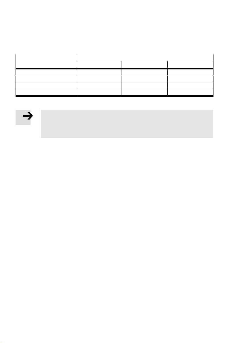
Use product only in the following mounting positions:
Handling system Mounting position
1)
X-module Y-module Z-module
Single-axis system – Horizontal –
Linear gantry – Horizontal Ver ti cal
Planar surface gantry Horizontal Horizontal –
Three-dimensional gantry Horizontal Horizontal Ve rti cal
1) Related illustrations (è 3.2 Module types).
Note
Deviating mounting positions or overhead mounting are not permitted. Energy chains
sag due to gravity. Cables and hoses are overloaded.
Use product only in a permitted mounting position.
1.5 Requirements for product use
Provide this documentation to the following persons:
– design engineer
– installer
– commissioner of the machine or system
Comply with the specifications of the documentation. Follow all accompanying documentation and
the documentation of any associated accessories.
Take the following into consideration for the destination:
– applicable legal regulations
– regulations and standards
– regulations of the testing organisations and insurers
– national specifications
For correct and safe use, take the following into account:
– all warnings and notes
– all load limits of the product and the connected components (è 1.1 Technical data)
8 Festo – GDCP-YXC-EN – 1502NH – English
Page 9

1 Safety and requirements for product use
1.5.1 Obligations of the operating company
The product is an incomplete machine.
Commissioning is prohibited until it has been established that the machinery in which it will be installed
is in compliance with the provisions of the Machinery Directive 2006/42/EC.
1.5.2 Qualified specialized personnel
Installation, mounting, commissioning, maintenance, repair and de-commissioning should only be per
formed by qualified personnel who are familiar with:
– installation and operation of electrical control systems
– installation and operation of pneumatic systems
– mounting and operation of mechatronic handling systems
– the applicable regulations for accident prevention and occupational safety
– the documentation and mode of operation of the product.
1.5.3 Range of application and certifications
Standards and test values that the product complies with and fulfills (è 1.1 Technical data).
Festo – GDCP-YXC-EN – 1502NH – English 9
Page 10
2 Conveying and storage
2 Conveying and storage
2.1 Conveying
The handling system is attached to the transport protection crate.
Note
Damage to the product due to incorrect transport.
Observe the markings for transport on the transport-protection crate.
Set the transport-protection crate on a firm and flat base.
2.2 Storage conditions
Comply with storage conditions (è 1.1 Technical data)
Storage conditions
Ambient conditions of the
storage location
2.3 Unpacking
Note
Damage to the product due to incorrect unpacking.
Observe the markings for unpacking on the transport-protection crate.
Unpack product with at least 2 persons.
Use correct tools.
Parts of the transport-protection crate are large and heavy; do not let them fall onto
the product.
Dry, solid and flat base, in original transport-protection crate
Remove marked transport protection aids (è 2.4.1 Securing in the transport protection crate).
10 Festo – GDCP-YXC-EN – 1502NH – English
Page 11
2 Conveying and storage
2.4 Transport protection aids
Three different types of transport protection aids prevent uncontrolled movement of the product during
unpacking, transport to the mounting location and installation.
Note
Keep the safety components for later use, e.g. for maintenance or dismantling.
2.4.1 Securing in the transport protection crate
The product is fastened in the transport protection crate by means of labelled screws.
Caution
Transport protection aids connected to the transport protection crate are not removed
completely. Transport protection crate breaks away when the product is lifted and falls
down.
Injury due to impact or pinching. Damage to the product.
Before the product is removed from the transport protection crate:
Remove all transport protection aids marked with this symbol (screws).
2.4.2 Securing when lifting
Warning
Product is heavy. The centre of gravity is not in the middle.
Injury due to impact or pinching. Damage to the product.
When lifting the product, carry out the following actions:
Use lifting points (e.g. lifting eye bolts) on the transport component kit.
Attach transport belts vertically to prevent the system from bending.
Use appropriate lifting gear (traverse) for safe handling.
Take weight into account (è Label on transport protection crate).
Take adequate safety precautions.
Assign sufficient number of people for mounting.
Adjust lifting speed.
Festo – GDCP-YXC-EN – 1502NH – English 11
Page 12
2 Conveying and storage
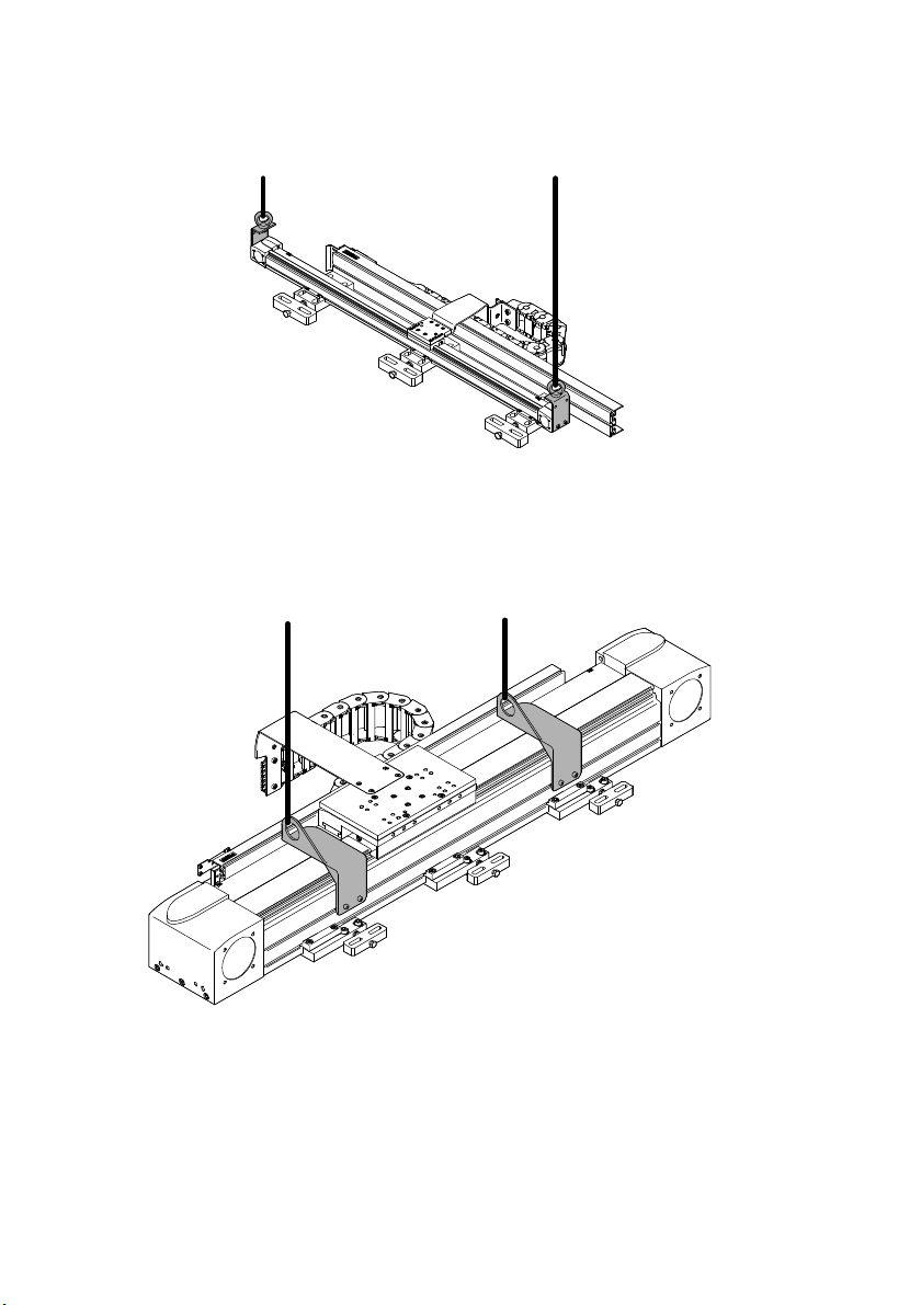
For the single-axis system and the linear gantry with EGC 50
To lift the handling system safely:
Use mounted transport component kit.
For the single-axis system and the linear gantry with EGC80/120/185 and EGC-HD
To lift the handling system safely:
Use mounted transport component kit.
12 Festo – GDCP-YXC-EN – 1502NH – English
Page 13
2 Conveying and storage
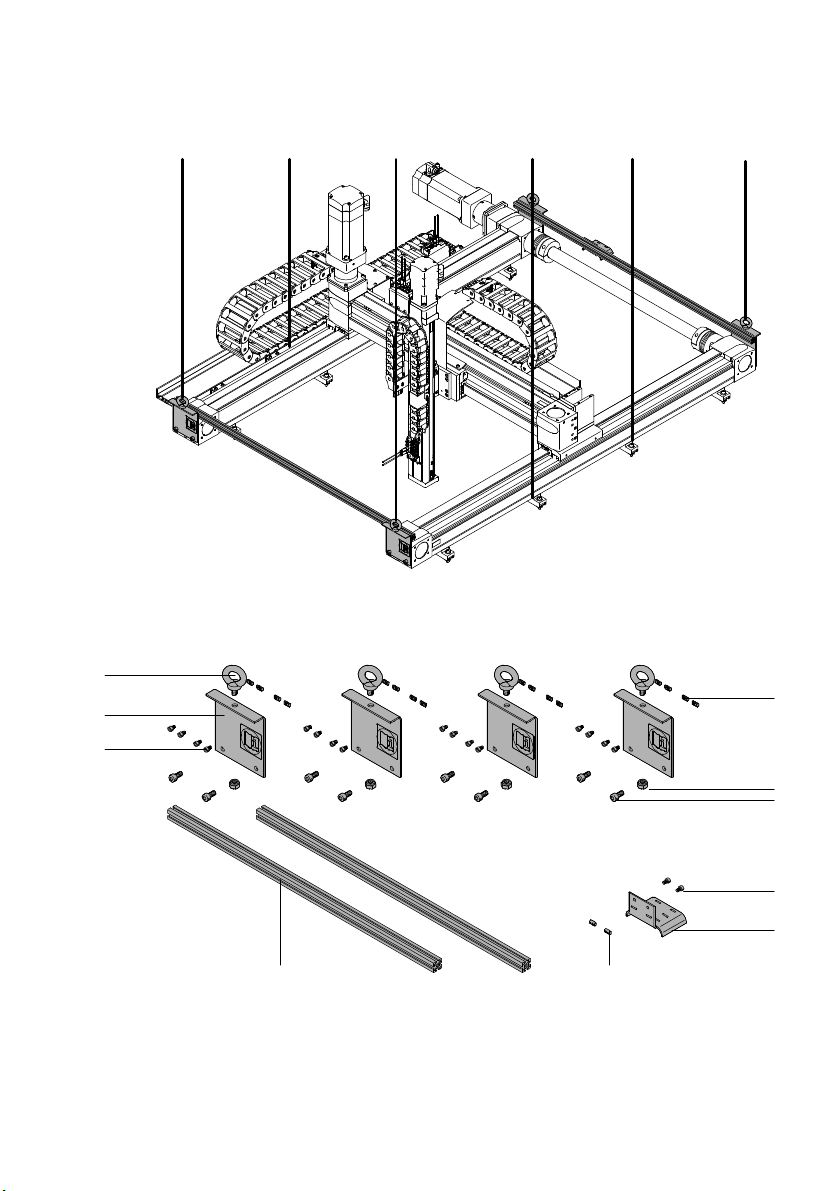
For the planar surface gantry and the three-dimensional gantry
To lift the handling system safely:
Use the following transport component kit.
2
1
3
aJ
4
5
6
7
89
1 Mounting bracket (4x)
2 Lifting eye bolt (4x)
3 Slot nut (8 … 16x)
4 Nut (4x)
5 Screw (8x)
Festo – GDCP-YXC-EN – 1502NH – English 13
6 Screw (2x)
7 Cable guide (1x)
8 Slot nut (2x)
9 Stay (2x)
aJ Screw (8 … 16x)
Page 14
2 Conveying and storage
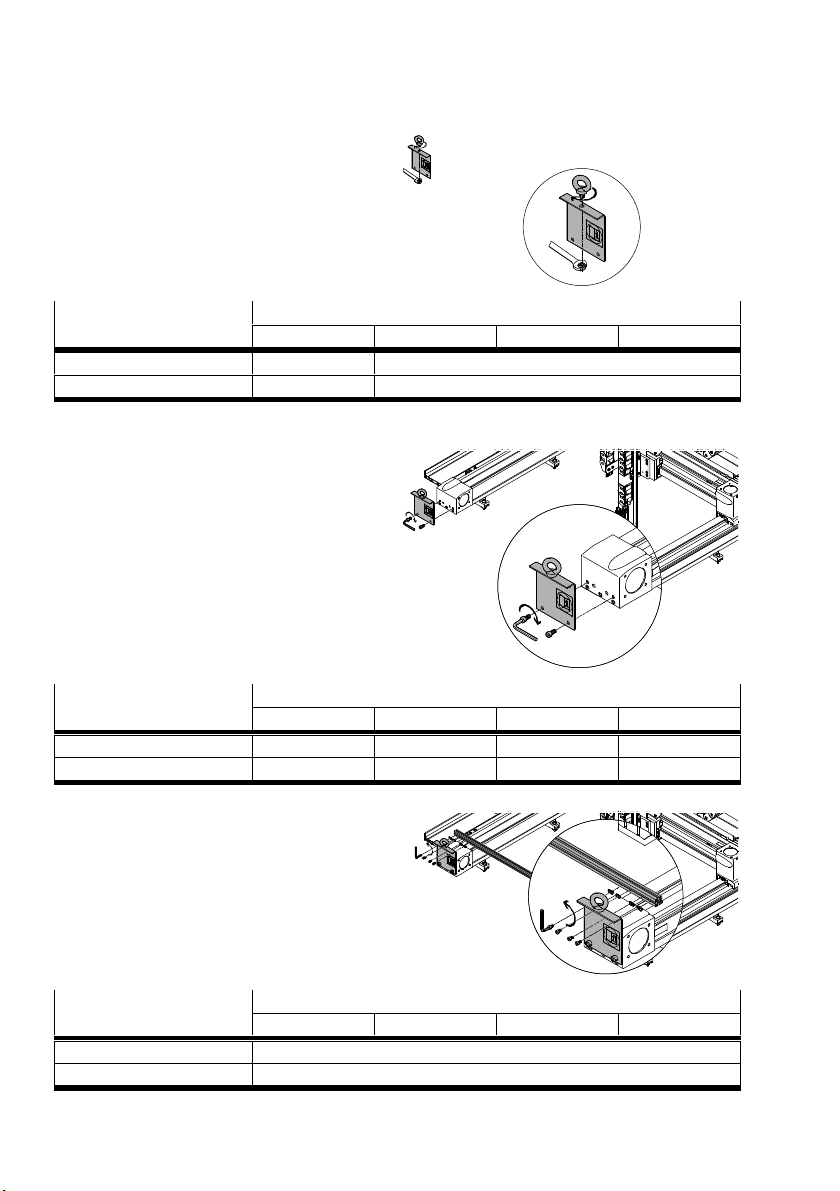
Fasten lifting eye bolts to mounting brackets
with the nut.
Screw size and tightening
torque
EHMX-EGC50 80 120 185
M8 M12
[Nm] 12 24
Attach the mounting bracket to the front sides
of the X-axes.
Screw size and tightening
torque
EHMX-EGC50 80 120 185
M4x10 M5x12 M8x16 M10x16
[Nm] 4.1 8.3 34 47
For clamping the Y-width (By):
Fasten stays with the slot nuts to the
mounting brackets.
Screw size and tightening
torque
EHMX-EGC50 80 120 185
M5x8
[Nm] 5.9
14 Festo – GDCP-YXC-EN – 1502NH – English
Page 15
2 Conveying and storage
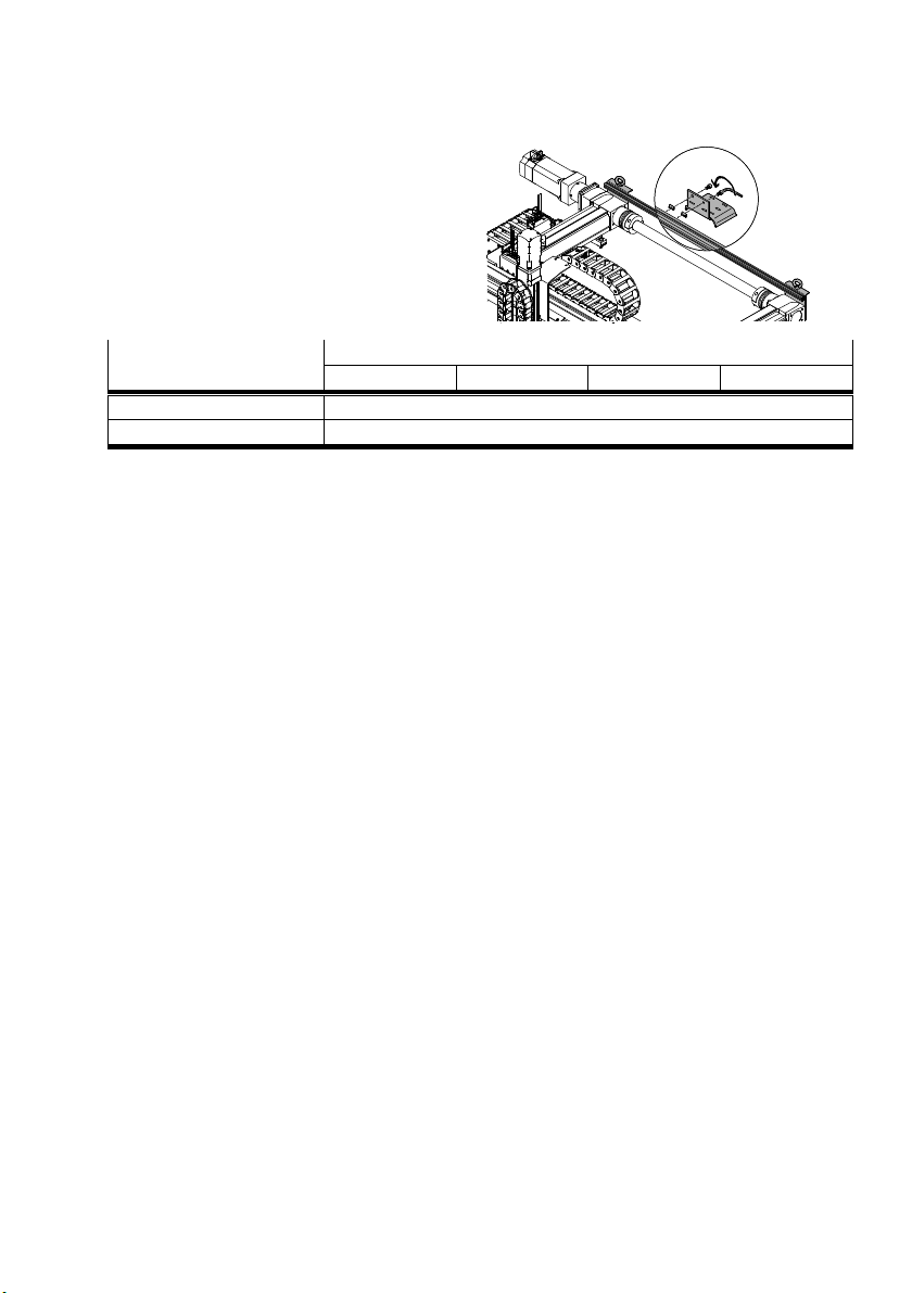
For clamping the cables and hoses
Position cable guide on the drive side at the
stay.
Fasten the cable guide with the slot nuts.
Wrap cables and hoses around the cable
guide and clamp them with cable ties.
Screw size and tightening
torque
[Nm] 5.9
EHMX-EGC50 80 120 185
M5x8
Festo – GDCP-YXC-EN – 1502NH – English 15
Page 16
2 Conveying and storage
2.4.3 Securing during transport and mounting
Moving parts are secured during transport of the product to prevent them from sliding.
Danger
Moving parts are secured. Product is energised. Moving parts break free and run uncon
trollably and with high acceleration into the end position.
Injury (death) due to impact or pinching.
To place the product safely in operation:
After mounting, remove all safety components marked with this symbol before ener
gising the product.
Safety component group at the Z-module
A Z-module with motor from Festo has a brake function. There are no moving parts to secure there.
For the Z-module without motor from Festo:
For the long-stroke Z-module (EMHZ-DGEA/EHMZ-EGC), the drive shaft is clamped through a safety
component group.
For the short-stroke Z-module (EHMZ-EGSL/DHMZ-DGSL), the moving parts do not need to be secured.
The slide can move.
When removing the safety component group at the Z-module:
Warning
Moving parts are secured. Safety component group is removed. Z-axis runs uncontrol
lably and with high acceleration into the end position.
Injury due to impact or pinching. Damage to the product.
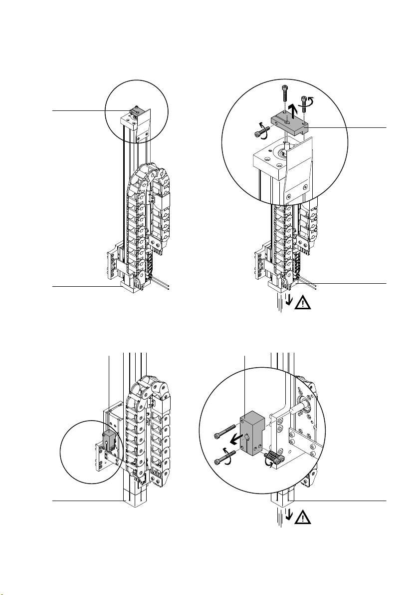
Remove the safety component group as follows:
1. Support Z-axis from below.
2. Remove safety component group.
3. Bring Z-axis slowly into the lower end position.
4. Mount motor.
16 Festo – GDCP-YXC-EN – 1502NH – English
Page 17
2 Conveying and storage
EHMZ-DGEA
1
1
2
1 Safety component group 2 Z-axis
EHMZ-EGC
11
2 2
1 Safety component group 2 Z-axis
2
Festo – GDCP-YXC-EN – 1502NH – English 17
Page 18

3 Overview
3Overview
The handling systems are based on 3 module types: X-module, Y-module and Z-module.
All illustrations show an example for the structure of the modules and handling systems.
The actual design differs depending on size and the order.
3.1 Delivery status
Depending on the order, the handling system is shipped as follows.
3.1.1 Completely mounted handling system
All modules are connected to each other. Motors are mounted onto the modules (exception: middle
motor position for the X-module). Cables and hoses are installed. Controllers and controller accessories
accompany the shipment.
3.1.2 Partially mounted handling system
The modules are not connected to each other. Motors are mounted onto the modules (exception:
middle motor position for the X-module). Cables and hoses, controllers and controller accessories ac
company the shipment.
3.2 Module types
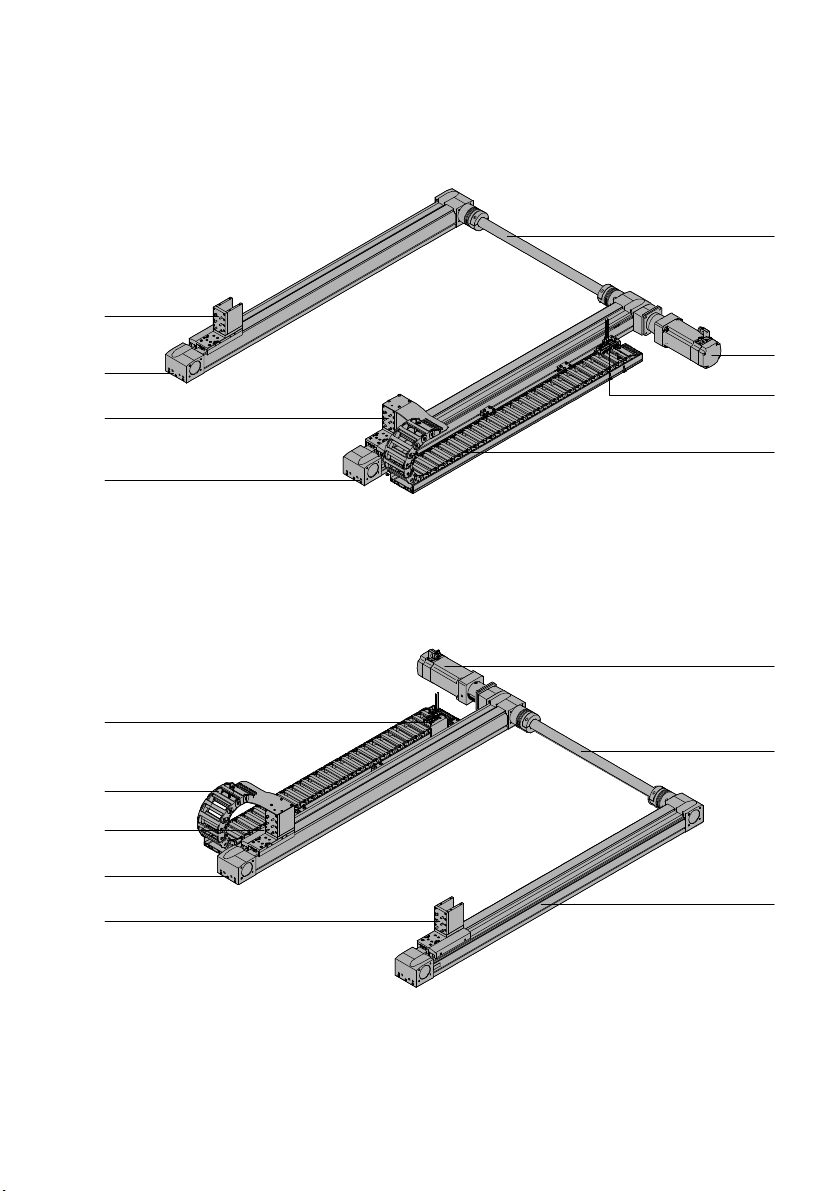
3.2.1 X-module EHMX (including motor)
The X-module consists of 2 parallel linear axes with a shared electric drive.
The X-module moves the Y-module along the X-axes.
Adapters are mounted on the slides of the X-axes to connect the Y-module.
Structure
The motor is connected to both X-axes through a connecting shaft. The position of the motor and en
ergy chain is dependent on the order.
The following components are located on the motor side:
Energy chain
Multi-pin plug for sensors (optional)
18 Festo – GDCP-YXC-EN – 1502NH – English
Page 19
3 Overview
Motor position right (EHMX-...-R)
8
1
7
6
5
1 Connecting shaft
2 Motor (optional)
3 Multi-pin plug/sensors (optional)
4 Energy chain
Motor position left (EHMX-...-L)
8
7
6
5
4
2
3
4
5 X-axis
6 Adapter Y-module
7 X-axis
8 Adapter Y-module
1
2
3
1 Motor (optional)
2 Connecting shaft
3 X-axis
4 Adapter Y-module
Festo – GDCP-YXC-EN – 1502NH – English 19
5 X-axis
6 Adapter Y-module
7 Energy chain
8 Multi-pin plug/sensors (optional)
Page 20
3 Overview
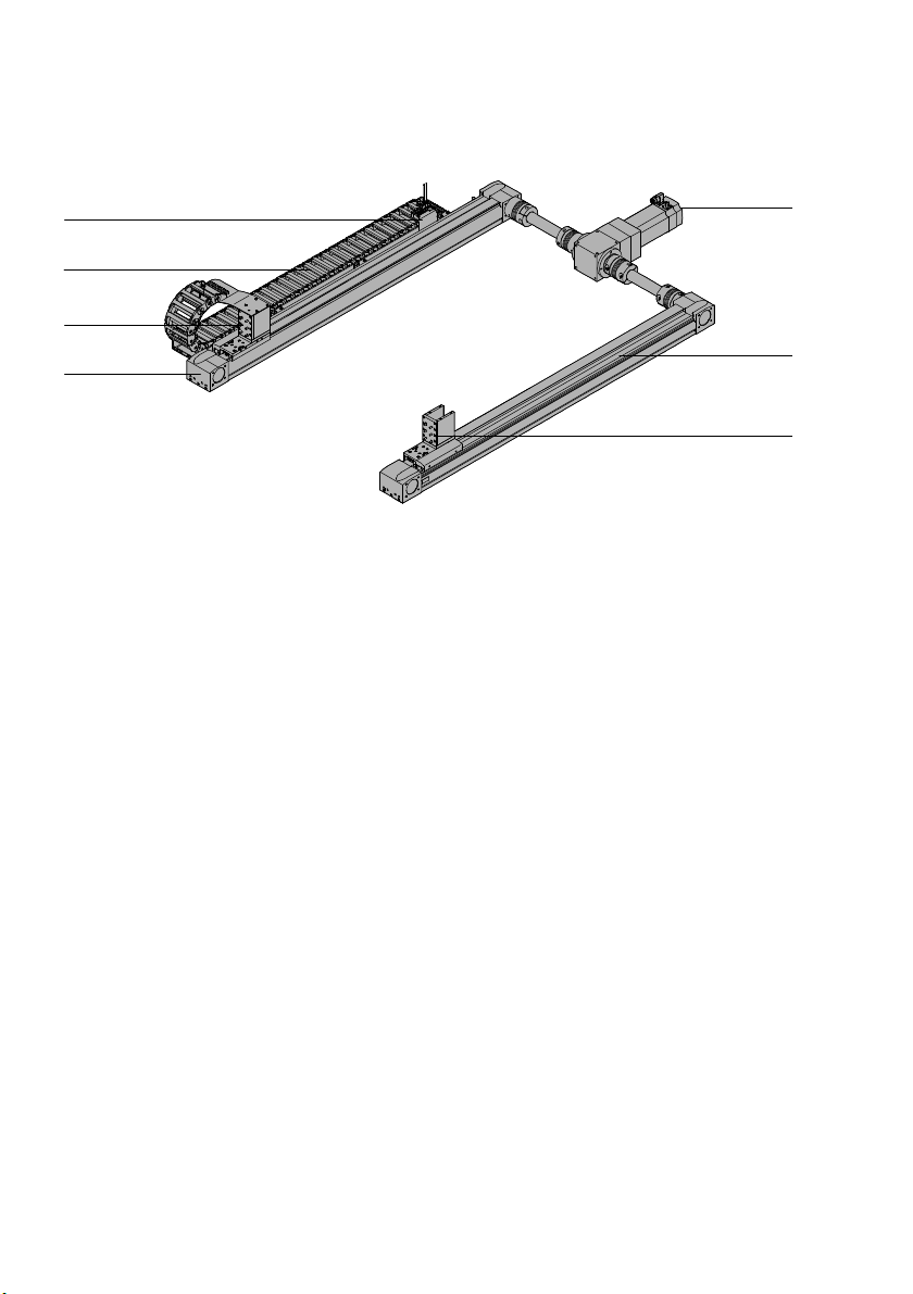
Motor position middle (EHMX-...-M)
7
6
5
4
1 Connecting shaft with gear unit/motor
2 X-axis
3 Adapter Y-module
4 X-axis
1) Accompanying
1
2
3
1)
5 Adapter Y-module
6 Energy chain
7 Multi-pin plug/sensors (optional)
20 Festo – GDCP-YXC-EN – 1502NH – English
Page 21
3 Overview
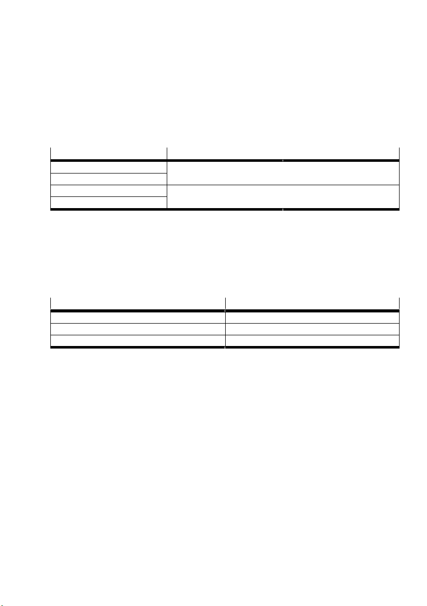
3.2.2 Y-module EHMY (including motor)
The Y-module consists of a linear axis with electric drive.
The Y-module moves the Z-module, or customer-provided attachments, along the Y-axis.
EHMY-LP: Y-module in the single-axis system or linear gantry
EHMY-RP: Y-module in the planar surface gantry or three-dimensional gantry
The main difference is the mounting option.
Handling system
Attachment of the Y-module
Single-axis system EHMY-LP on mounting surface
Linear gantry
Three-dimensional gantry EHMY-RP to X-module
Planar surface gantry
Structure
For the single-axis system and the linear gantry, the position of the motor on the Y-module is dependent
on the order.
For the planar surface gantry and the three-dimensional gantry, the position of the motor on the Y-mod
ule is dependent on the position of the motor on the X module.
Motor X-module Motor Y-module
Right Right
Middle Left
Left Left
The following components are located on the motor side:
– Input and output of the energy chain
– Multi-pin plug for sensors (optional)
Festo – GDCP-YXC-EN – 1502NH – English 21
Page 22
3 Overview
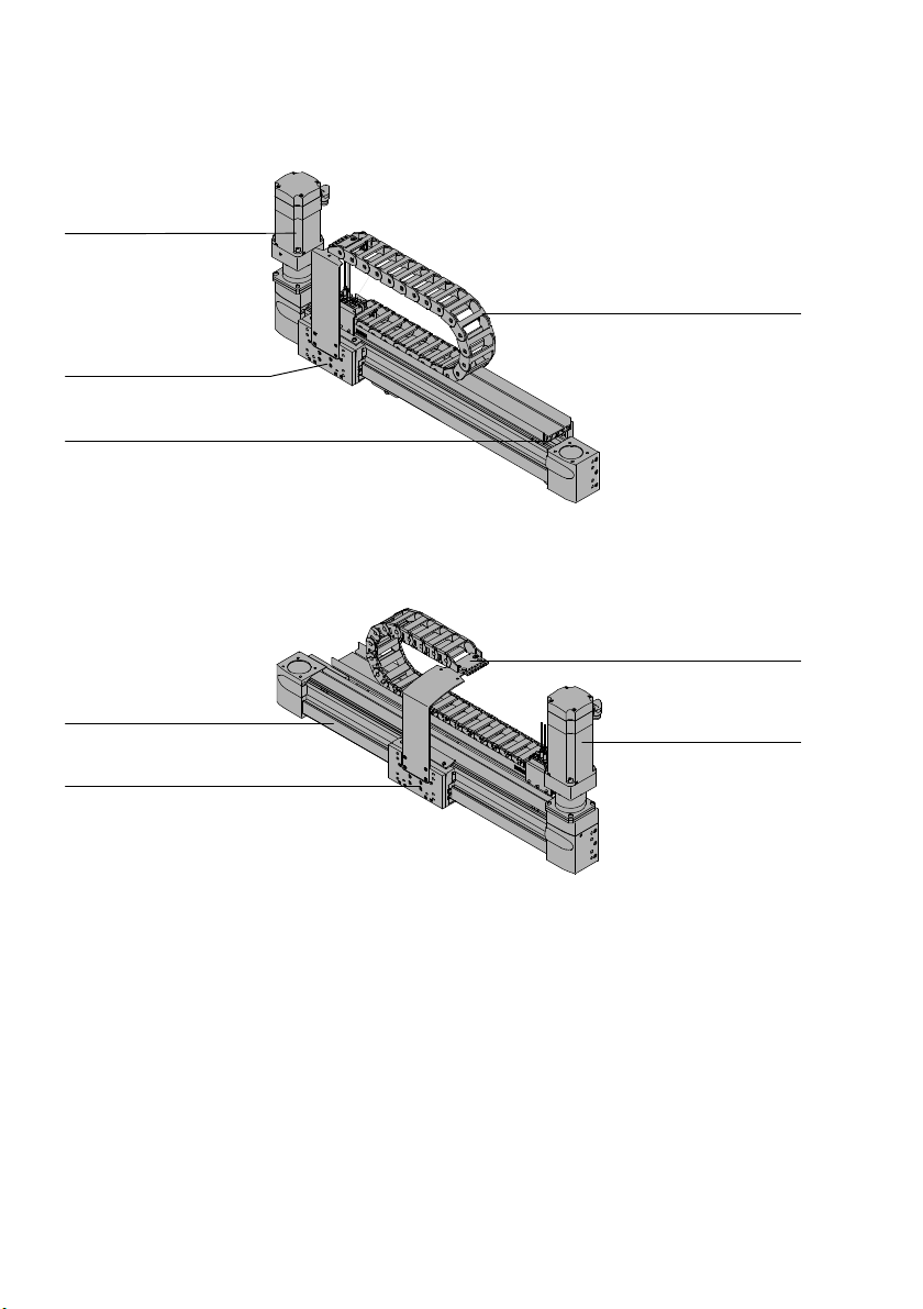
Y-module for single-axis system/linear gantry EHMY-LP
3
2
1
4
1 Y-axis
2 Adapter Z-module/attachment components
3 Motor left (optional)
4 Energy chain
Y-module for planar surface gantry/three-dimensional gantry EHMY-RP
1
2
1 Y-axis
2 Adapter Z-module/attachment components
3 Motor right (optional)
4 Energy chain
4
3
22 Festo – GDCP-YXC-EN – 1502NH – English
Page 23
3 Overview
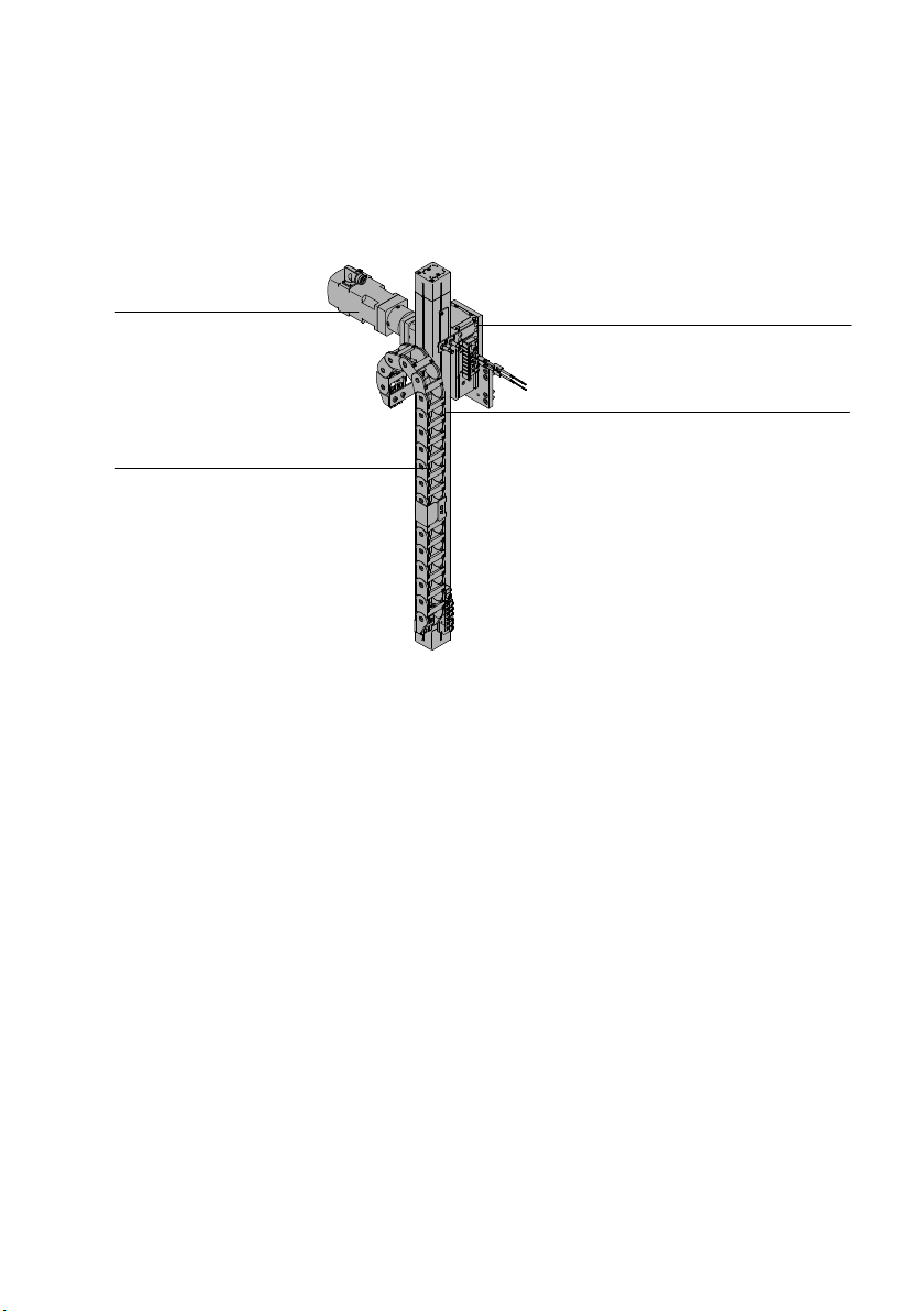
3.2.3 Z-module EHMZ (including motor)/DHMZ
The Z module consists of an electric or pneumatic drive.
The Z-module moves customer-provided attachments, along the Z-axis.
Structure
4
3
1 Adapter on Y-module
2 Z-axis
1
2
3 Energy chain
4 Motor (optional)
Festo – GDCP-YXC-EN – 1502NH – English 23
Page 24
3 Overview
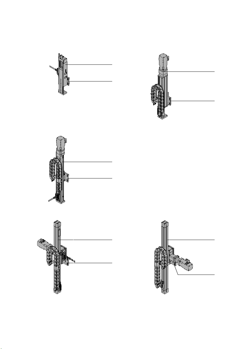
Depending on the order, a three-dimensional or linear gantry is equipped with the following Z-modules.
DHMZ-DGSL EHMZ-EGSL
2
2
1
1
EHMZ-EGC
2
1
EHMZ-DGEA (motor position left) (Motor position right)
2 2
1
1
1 Adapter on Y-module 2 Z-axis
24 Festo – GDCP-YXC-EN – 1502NH – English
Page 25
3 Overview
3.3 Handling systems
A handling system consists of up to 3 modules.
Handling system X-module Y-module Z-module
Single-axis system – EHMY-LP
Linear gantry – EHMY-LP
Planar surface gantry EHMX
Three-dimensional gantry EHMX
1) Basic module with 2 parallel axes
2) Basic module
1)
1)
EHMY-RP –
EHMY-RP EHMZ/DHMZ
Observe the mounting position (è 1.4 Permitted mounting position).
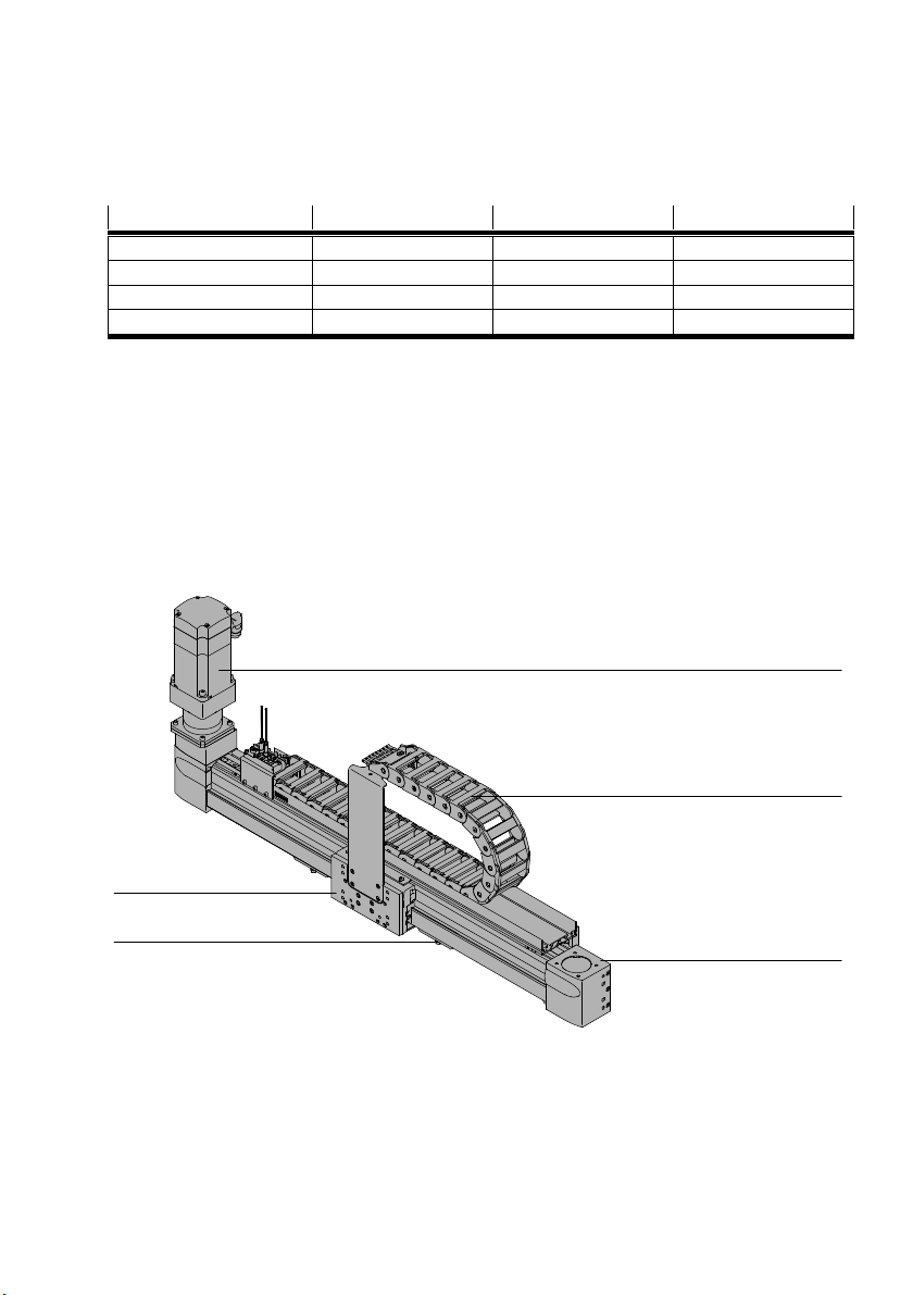
3.3.1 Single-axis system YXCS
Function
The single-axis system moves a customer-provided attachment linearly.
Structure
The following figure shows an example for the fundamental structure of the single-axis system.
2)
2)
–
EHMZ/DHMZ
3
2
4
5
1
1 Y-axis
2 Energy chain
4 Adapter, attachment components
5 Mounting components
3 Motor (optional)
Festo – GDCP-YXC-EN – 1502NH – English 25
Page 26
3 Overview
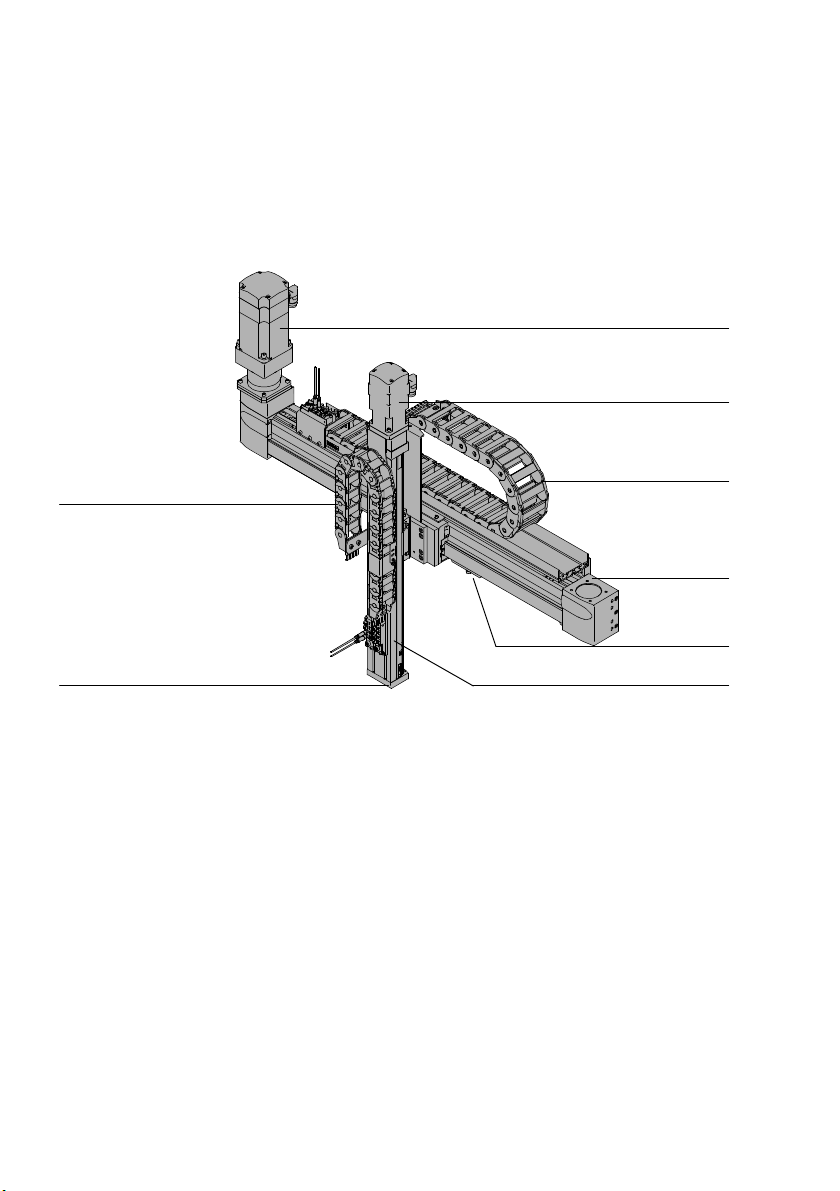
3.3.2 Linear gantry YXCL
Function
The linear gantry moves a customer-provided attachment within a vertical plane.
Structure
The following figure shows an example for the fundamental structure of the linear gantry.
7
6
5
4
3
2
8
1 Z-axis
2 Mounting components
3 Y-axis
4 Energy chain Y
26 Festo – GDCP-YXC-EN – 1502NH – English
5 Motor Z (optional)
6 Motor Y (optional)
7 Energy chain Z
8 Adapter, attachment components
1
Page 27
3 Overview
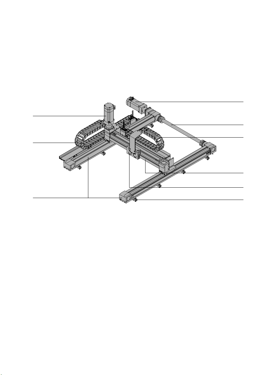
3.3.3 Planar surface gantry YXCF
Function
The planar surface gantry moves a customer-provided attachment within a horizontal plane.
Structure
The following figure shows an example for the fundamental structure of the planar surface gantry.
3
4
5
2
1
1 X-axes
2 Energy chain X
3 Motor Y (optional)
4 Motor X (optional)
5 Connecting shaft
1) Dependent on order
6 Energy chain Y
7 Y-axis
8 Adapter, attachment components
9 Mounting components
1)
6
7
8
9
Festo – GDCP-YXC-EN – 1502NH – English 27
Page 28
3 Overview
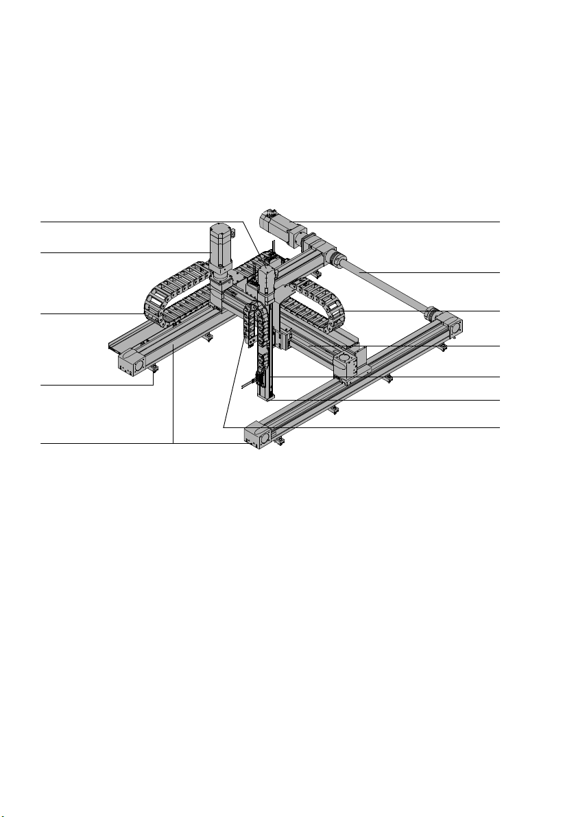
3.3.4 Three-dimensional gantry YXCR
Function
The three-dimensional gantry moves a customer-provided attachment within a space.
Structure
The following figure shows an example for the fundamental structure of the three-dimensional gantry.
5 6
4
7
3
2
1
1 X-axes
2 Mounting components
3 Energy chain X
4 Motor Y (optional)
5 Motor Z (optional)
6 Motor X (optional)
1) Dependent on order
8
9
aJ
aA
aB
1)
7 Connecting shaft
8 Energy chain Y
9 Y-axis
aJ Z-axis (electrical/pneumatic)
aA Adapter, attachment components
aB Energy chain Z
28 Festo – GDCP-YXC-EN – 1502NH – English
Page 29
3 Overview
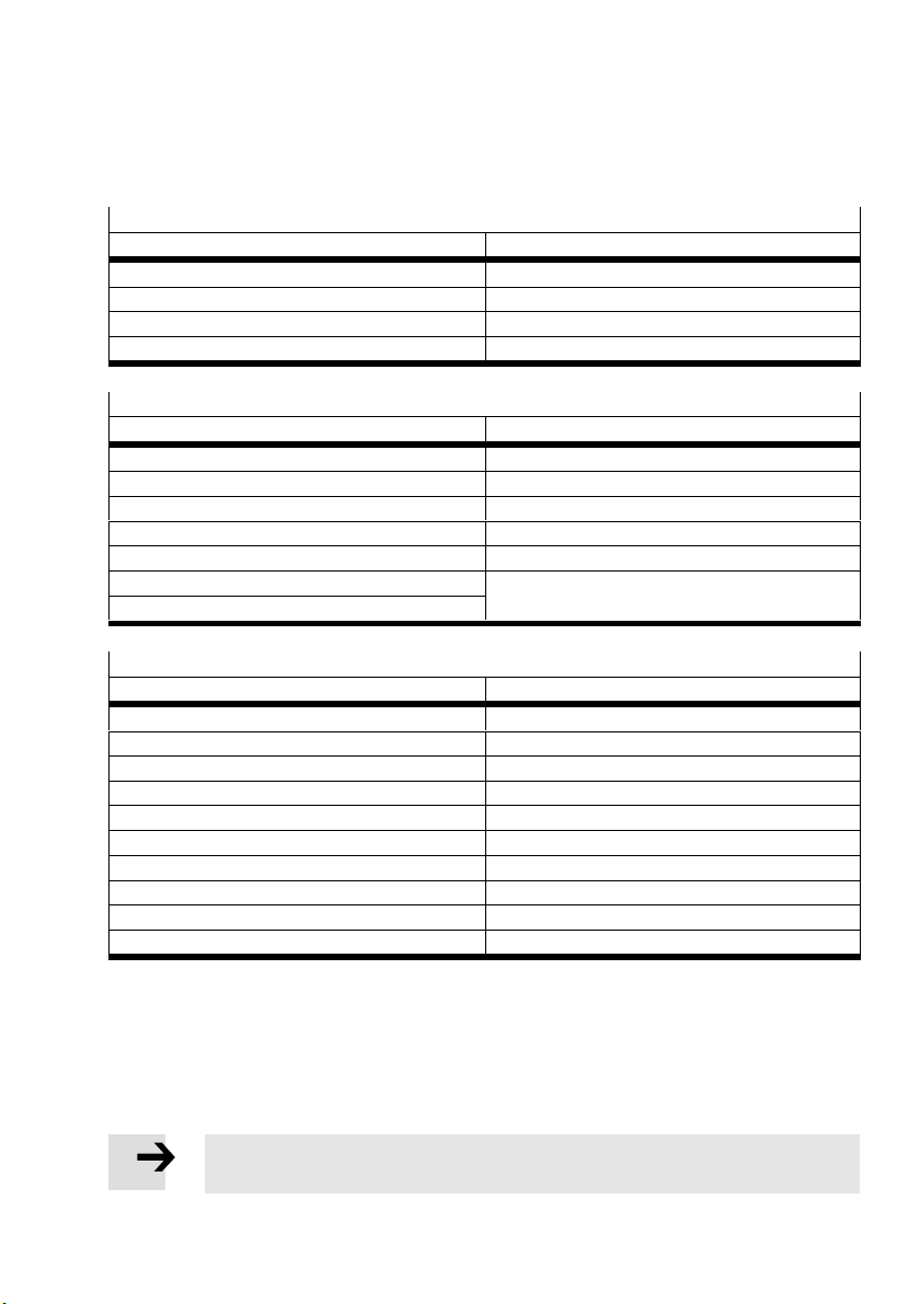
3.4 Handling systems without motors
Use the following motors from Festo (recommended).
X-module EHMX
Axes Motor
EGC-50-TB-KF EMMS-AS-40-M-LS-…
EGC-80-TB-KF EMMS-AS-70-M-LS-…
EGC-120-TB-KF EMMS-AS-100-M-HS-…
EGC-185-TB-KF EMMS-AS-140-L-HS-…
Y-module EHMY
Axis Motor
EGC-50-TB-KF EMMS-AS-40-M-LS-…
EGC-80-TB-KF EMMS-AS-70-S-LS-…
EGC-120-TB-KF EMMS-AS-100-S-HS-…
EGC-125-TB-HD EMMS-AS-70-S-LS-…
EGC-160-TB-HD EMMS-AS-100-S-HS-…
EGC-185-TB-KF EMMS-AS-140-S-HS-…
EGC-220-TB-HD
Z-module EHMZ
Axis Motor
DGEA-18-TB-KF EMMS-AS-55-S-LS-...
DGEA-25-TB-KF EMMSAS70SLS…
DGEA-40-TB-KF EMMS-AS-100-S-HS-…
EGC70BSKF EMMS-AS-55-S-LS-...
EGC-80-BS-KF EMMSAS70SLS…
EGC-120-BS-KF EMMS-AS-100-S-HS-…
EGSL-35-BS-KF EMMS-ST-28-L-...
EGSL-45-BS-KF EMMS-AS-40-M-LS-...
EGSL-55-BS-KF EMMS-AS-55-S-LS-...
EGSL-75-BS-KF EMMSAS70SLS…
If you use motors from other manufacturers (not recommended):
Only use motors with comparable technical limits
(è www.festo.com/catalogue).
Comply with technical limits of the axes used in the modules
(è www.festo.com/catalogue).
Note
The product can be damaged if the technical limits are not complied with.
Festo – GDCP-YXC-EN – 1502NH – English 29
Page 30
4 Installation of the single-axis systems and the linear gantries
4 Installation of the single-axis systems and the linear
gantries
Observe safety instructions
Pay attention to transport protection
(è 2.4 Transport protection aids).
4.1 Preparation
4.1.1 Installation space
The installation space required depends on the order.
Take dimensions from the CAD model (è 1.1 Technical data).
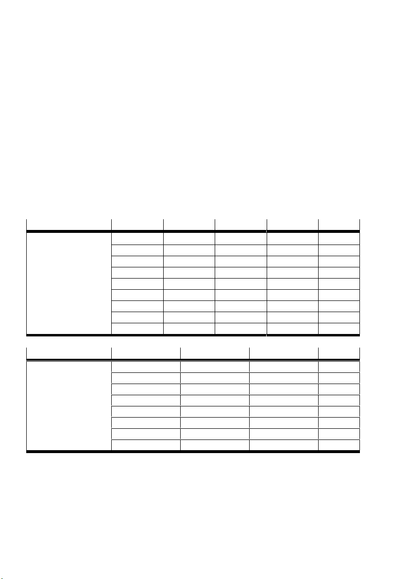
4.1.2 Number n of mounting components
EHMY-LP-EGC-…-KF 50 80 120 185 n
1)
Hy
[mm]
475 600 450 590
476 … 950 601 … 1150 451 … 1100 591 … 1220 3
951 … 1425 1151 … 1700 1101 … 1750 1221 … 1850 4
1426 … 1900 1701 … 2250 1751 … 2400 1851 … 2480 5
– 2251 … 2800 2401 … 3050 2481 … 3110 6
– 2801 … 3350 3051 … 3700 3111 … 3740 7
– 3351 … 3900 3701 … 4350 3741 … 4370 8
– 3901 … 4450 4351 … 4500 4371 … 4500 9
– 4451 … 4500 – – 10
2)
2
EHMY-LP-EGC-…-TB-HD 125 160 220 n
1)
Hy
[mm] 560 590 550 2
2)
561 … 1170 591 … 1220 551 … 1150 3
1171 … 1780 1221 … 1850 1151 … 1750 4
1781 … 2390 1851 … 2480 1751 … 2350 5
2391 … 3000 2481 … 3110 2351 … 2950 6
– 3111 … 3740 2951 … 3550 7
– 3741 … 4370 3551 … 4150 8
– 4371 … 4500 4151 … 4500 9
1) Hy = stroke in Y-direction (è 1.1 Technical data)
2) n = number of mounting components
30 Festo – GDCP-YXC-EN – 1502NH – English
Page 31
4 Installation of the single-axis systems and the linear gantries
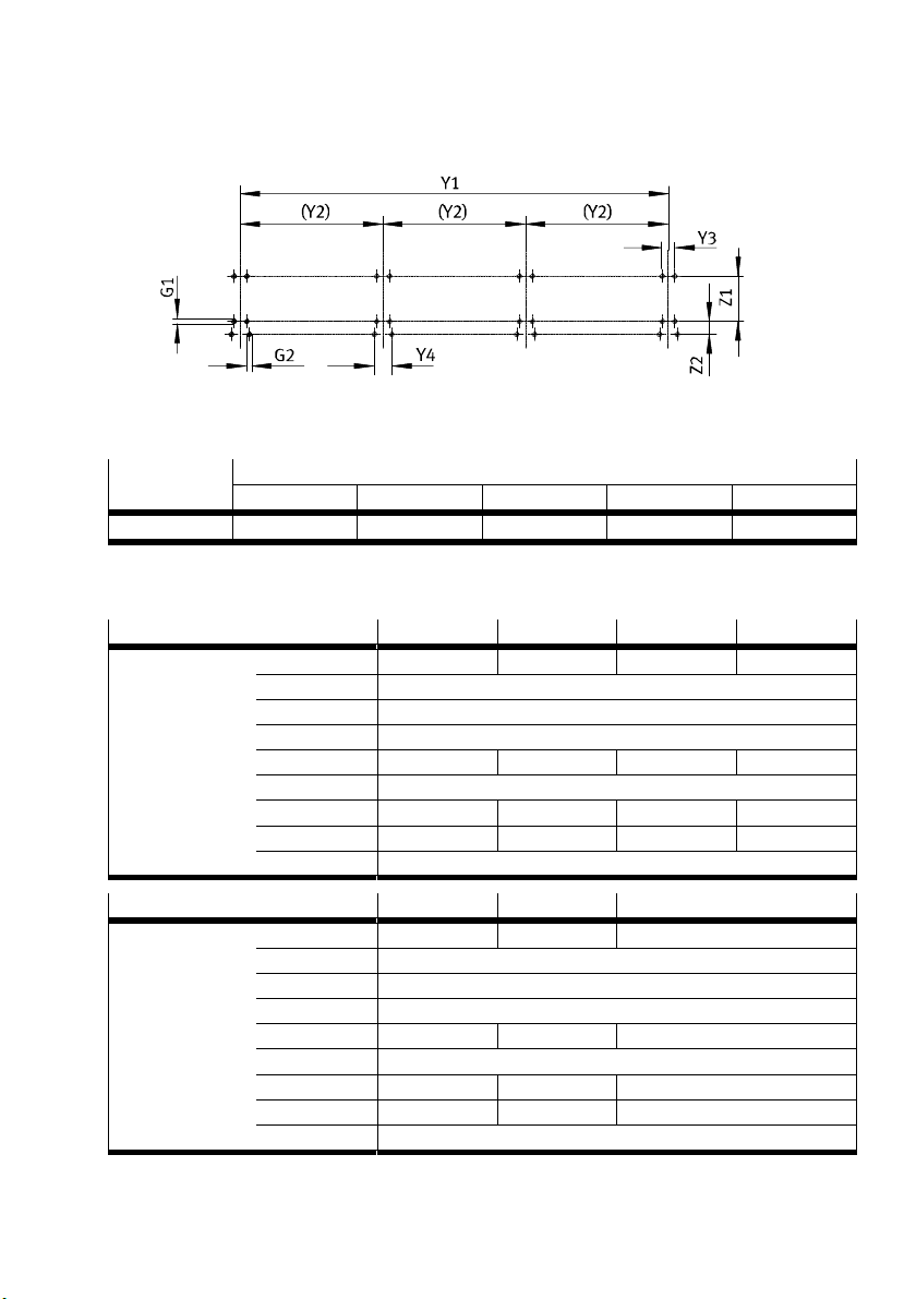
4.1.3 Preparation of the mounting surface
Ensure that the mounting surface is flat and vertical.
The required flatness depends on the length of the handling system.
Flatness Y1 [mm]
3 1000 1001 … 2000 2001 … 3000 3001 … 4000 4001 … 5000
[mm] 0.1 0.2 0.3 0.4 0.5
Prepare mounting option on mounting surface. Mounting kit of the intermediate mounting is mov
able. If required, change support spacing Y2.
EHMY-LP-EGC-...-KF 50 80 120 185
Y2
1)
2)
Hy 97 Hy 16 Hy 23 Hy + 67
Y1 / (n 1)
Dimensions [mm] Y1
Y3 40
Y4 55
Z1 80 125 140 220
Z2 40
G1 M4 M6 M8 M8
Depth of thread 9 9 13 13
G2 M8
EHMY-LP-EGC-...-HD 125 160 220
Y2
1)
2)
Hy + 60 Hy + 94 Hy + 90
Y1 / (n 1)
Dimensions [mm] Y1
Y3 40
Y4 55
Z1 180 220 260
Z2 40
G1 M6 M6 M8
Depth of thread 9 9 13
G2 M8
1) Hy = stroke in Y-direction (è 1.1 Technical data)
2) n = number of mounting components (è 4.1.2 Number n of mounting components)
Festo – GDCP-YXC-EN – 1502NH – English 31
Page 32
4 Installation of the single-axis systems and the linear gantries
4.2 Mounting components
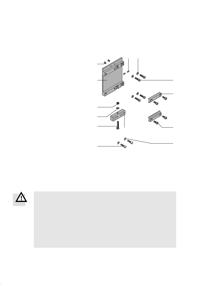
4.2.1 Mounting kit with adjustment possibility
Structure
1 Adjusting piece
2 Adjusting piece screw
3 Adjusting piece washer
4 Adjusting piece nut
5 Lower part
6 Support profile screw
7 Support profile slot nut
8 Lower part washer
9 Screw, lower part
aJ Upper part
aA Screw, upper part
(1x)
(1x)
678
(1x)
(1x)
(1x)
5
(2x)
(2x)
(4x)
1)
(4x)
(2x)
(4x)
4
3
9
aJ
2
1
Not included in delivery:
aB Washer
aC Screw M8
1) The screw and tightening torque are designed for mounting on steel.
2) Adjusting pieces (1 … 4) and screws (8 … 9) accompany the shipment. The remaining par ts are pre-assembled.
(2x)
(2x)
aC
Requirements
– Number n of mounting components is known (è 4.1.2 Number n of mounting components).
– Mounting surface is prepared (è 4.1.3 Preparation of the mounting surface).
Mounting
Warning
Incorrect mounting. Entire product moves uncontrollably.
Injury due to impact or pinching. Damage to the product.
Use screws 9 and aC with strength class of at least 8.8.
Select screws 9 and aC suitable for the installation situation.
Mount product free of distortion.
Use only the mounting kits supplied.
Secure threaded connections.
Make sure the mounting surface is sufficiently strong to absorb the maximum
forces.
aA
aB
32 Festo – GDCP-YXC-EN – 1502NH – English
Page 33
4 Installation of the single-axis systems and the linear gantries
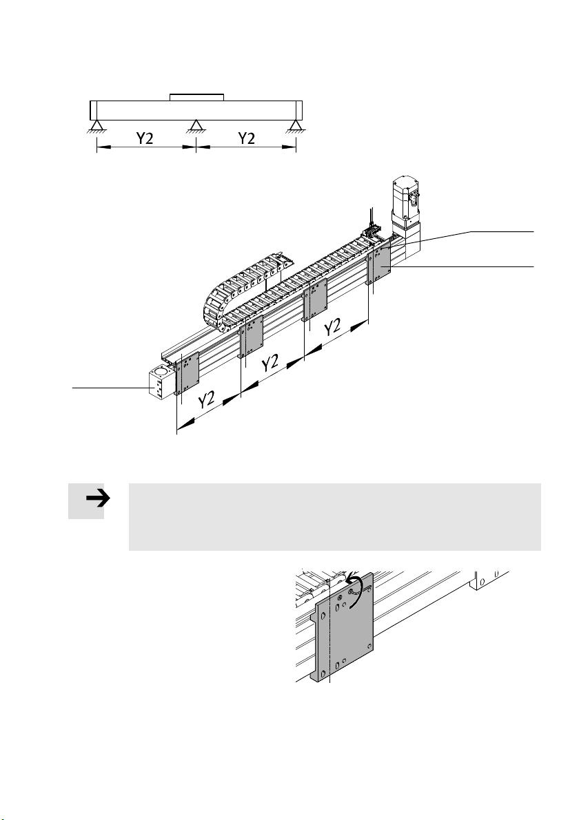
The mounting kits are pre-mounted to the
Y-module.
Check number n and support spacing Y2.
Place Y-module.
1
3
2
1 Y-module
3 Screw
2 Mounting kit
Note
In order to move the mounting kit, the screws 3 on the support profile of the energy
chain must be accessible from the reverse side after mounting.
Mount Y-module to a machine frame correspondingly.
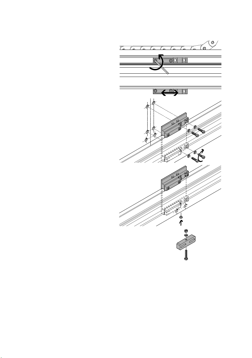
On the reverse side:
1. Unscrew screws on the support profile of
the energy chain.
Festo – GDCP-YXC-EN – 1502NH – English 33
Page 34
4 Installation of the single-axis systems and the linear gantries
On the front:
2. Unscrew screws on the upper parts.
3. Position lower part.
4. Place washers underneath the screws.
5. Using suitable screws1), lightly clamp lower
part to the mounting surface.
6. Press bolt from below into the intended
hole in the lower part.
7. Turn screw into the adjusting piece.
8. Place washer below the nut.
9. Screw nut onto the screw.
1) The accompanying screw and tightening torque are designed for mounting on steel.
34 Festo – GDCP-YXC-EN – 1502NH – English
Page 35
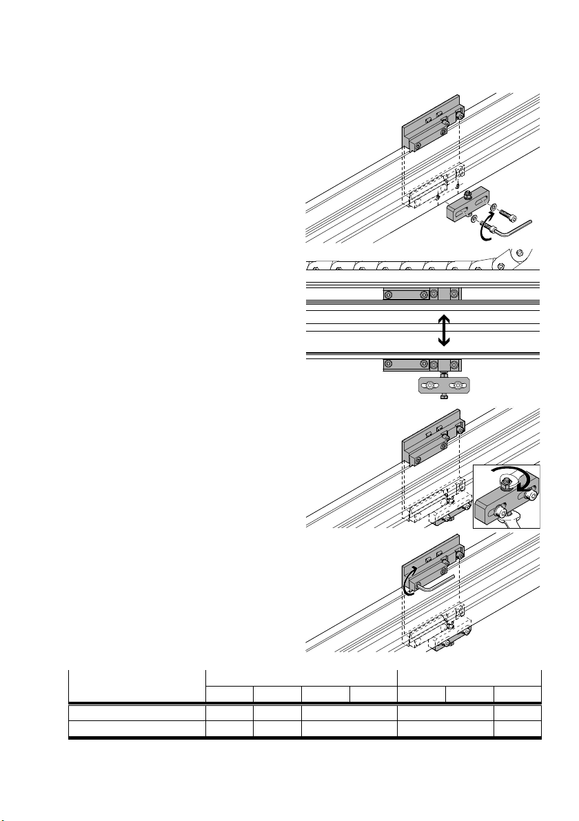
4 Installation of the single-axis systems and the linear gantries
10.Fasten adjusting piece to the mounting
surface with suitable screws.
11.Align Y-module horizontally as follows:
– Screw the screw on the adjusting piece
in or out.
12.Screw nut in tightly. Apply counter pressure
to screw. (Tightening torque 2.5 … 10 Nm)
Check:
– The screw has not twisted.
– The alignment has been maintained.
13.Evenly tighten screws.
Screw size and tightening
torque
EHMY-LP-EGC-...-KF EHMY-LP-EGC-...-HD
50 80 120 185 125 160 220
M3x8 M5x16 M8x20 M5x16 M8x20
[Nm] 1.7 5.9 20 5.9 20
Festo – GDCP-YXC-EN – 1502NH – English 35
Page 36
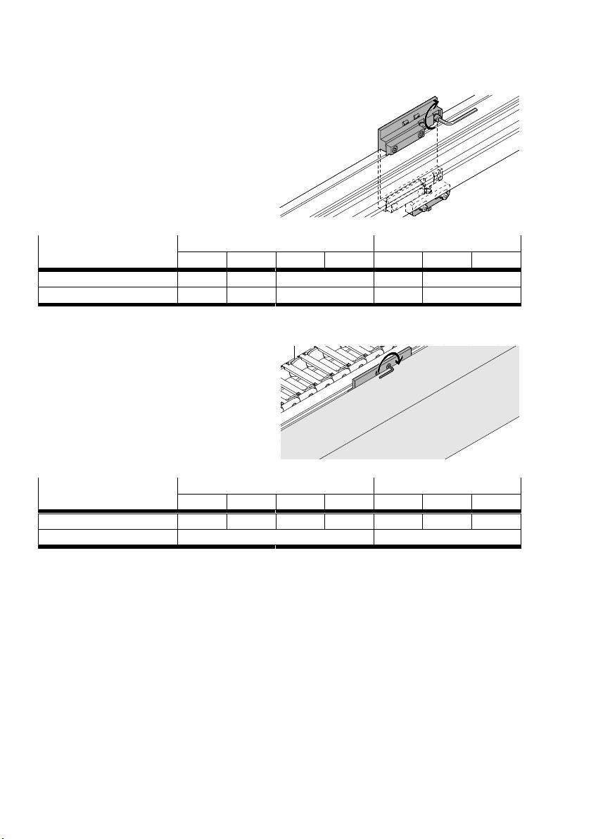
4 Installation of the single-axis systems and the linear gantries
14.Evenly tighten appropriate screws1).
Screw size and tightening
1)
torque
EHMY-LP-EGC-...-KF EHMY-LP-EGC-...-HD
50 80 120 185 125 160 220
M4x16 M6x20 M8x30 M6x20 M8x30
[Nm] 2.9 14 20 14 20
1) Accompanying screw and tightening torque are designed for mounting on steel.
On the reverse side:
For mounting onto a machine frame:
15.Evenly tighten screw on the support profile
of the energy chain.
Screw size and tightening
torque
EHMY-LP-EGC-...-KF EHMY-LP-EGC-...-HD
50 80 120 185 125 160 220
M5x8 M5x8 M5x12 M5x12 M5x10 M5x10 M5x10
[Nm] 8.3 8.3
36 Festo – GDCP-YXC-EN – 1502NH – English
Page 37
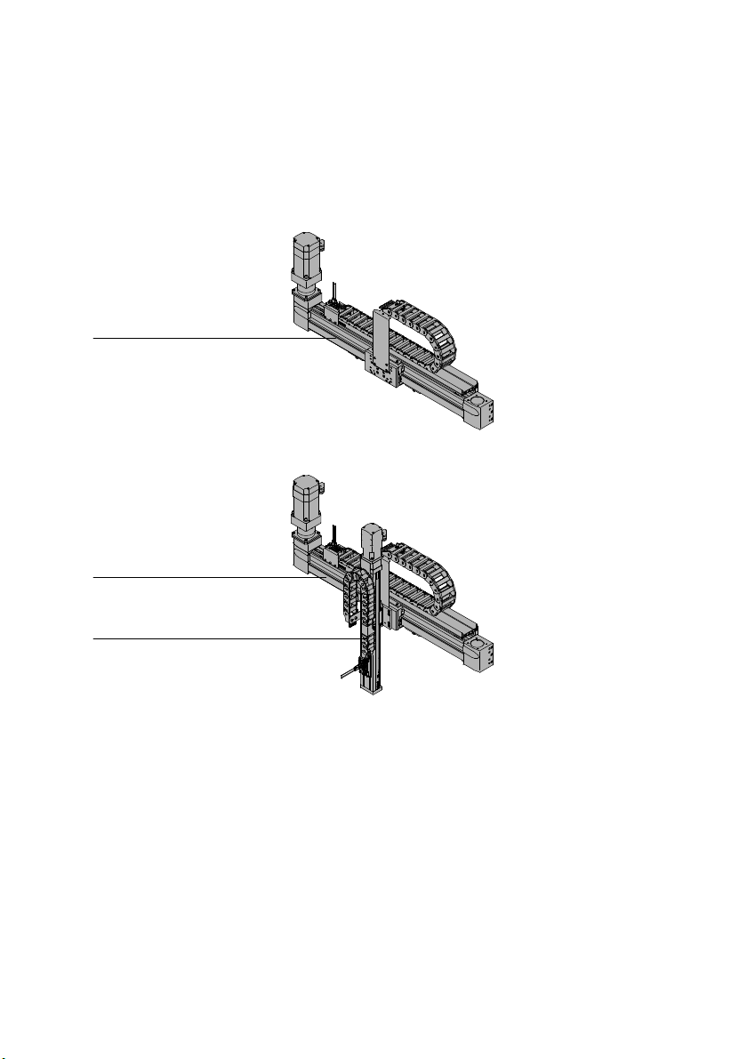
4 Installation of the single-axis systems and the linear gantries
4.3 Installation of single-axis system and linear gantry
4.3.1 Installation YXCS/YXCL
Structure
Single-axis system YXCS
1
Linear gantry YXCL
1
2
1 Y-module 2 Z-module
Requirements
– Mounting surface is prepared (è 4.1.3 Preparation of the mounting surface ).
– Transport protection in the shipping crate is removed
(è 2.4.1 Securing in the transport protection crate).
– Transport protection for lifting is mounted (è 2.4.2 Securing when lifting ).
– Function of the mounting components is known (è 4.2.1 Mounting kit with adjustment possibility).
Festo – GDCP-YXC-EN – 1502NH – English 37
Page 38
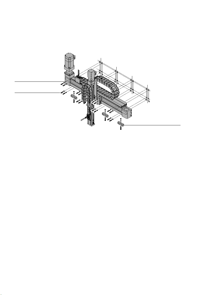
4 Installation of the single-axis systems and the linear gantries
Installation
Place handling system slowly and carefully onto the prepared mounting surface.
Align Y-module (base module) horizontally and fasten it.
1
2
3
1 Y-axis
2 Screw set
3 Adjusting piece
38 Festo – GDCP-YXC-EN – 1502NH – English
Page 39
5 Installation of the planar surface gantries and the three-dimensional gantries
5 Installation of the planar surface gantries and the
three-dimensional gantries
Observe safety instructions and notes on installation.
Pay attention to transport protection (è 2.4 Transport protection aids).
5.1 Preparation
5.1.1 Installation space
The installation space required depends on the order.
Take dimensions from the CAD model (è 1.1 Technical data).
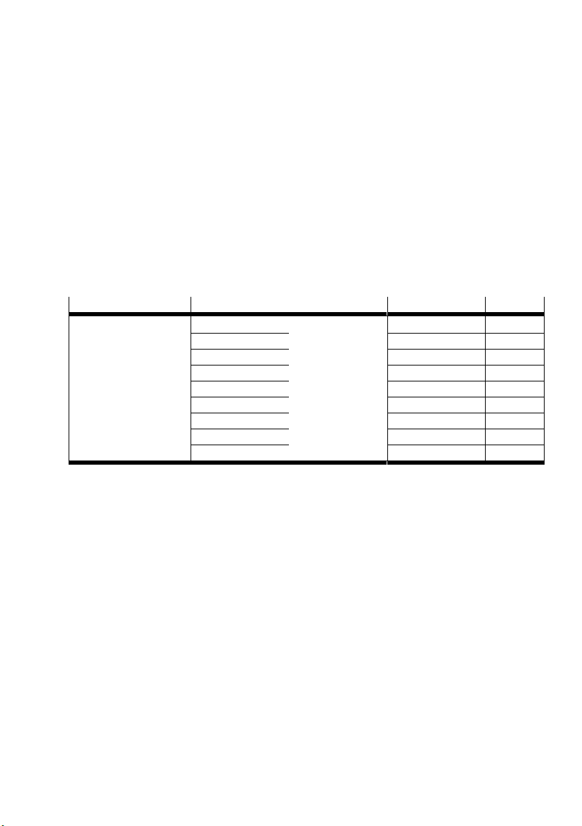
5.1.2 Number n of mounting components
EHMX-EGC- 50 80 120/185 n
1)
Hx
1) Hx = stroke in X-direction (è 1.1 Technical data)
2) n = total number of mounting components for both X-axes
[mm]
475 400 450
476 … 950 401 … 1100 451 … 1100 6
951 … 1425 976 … 1550 1101 … 1750 8
1426 … 1900 1551 … 2125 1751 … 2400 10
– 2126 … 2700 2401 … 3050 12
– 2701 … 3275 3051 … 3700 14
– 3276 … 3850 3701 … 4350 16
– 3851 … 4425 4351 … 4500 18
– 4426 … 4500 – 20
2)
4
Festo – GDCP-YXC-EN – 1502NH – English 39
Page 40
5 Installation of the planar surface gantries and the three-dimensional gantries
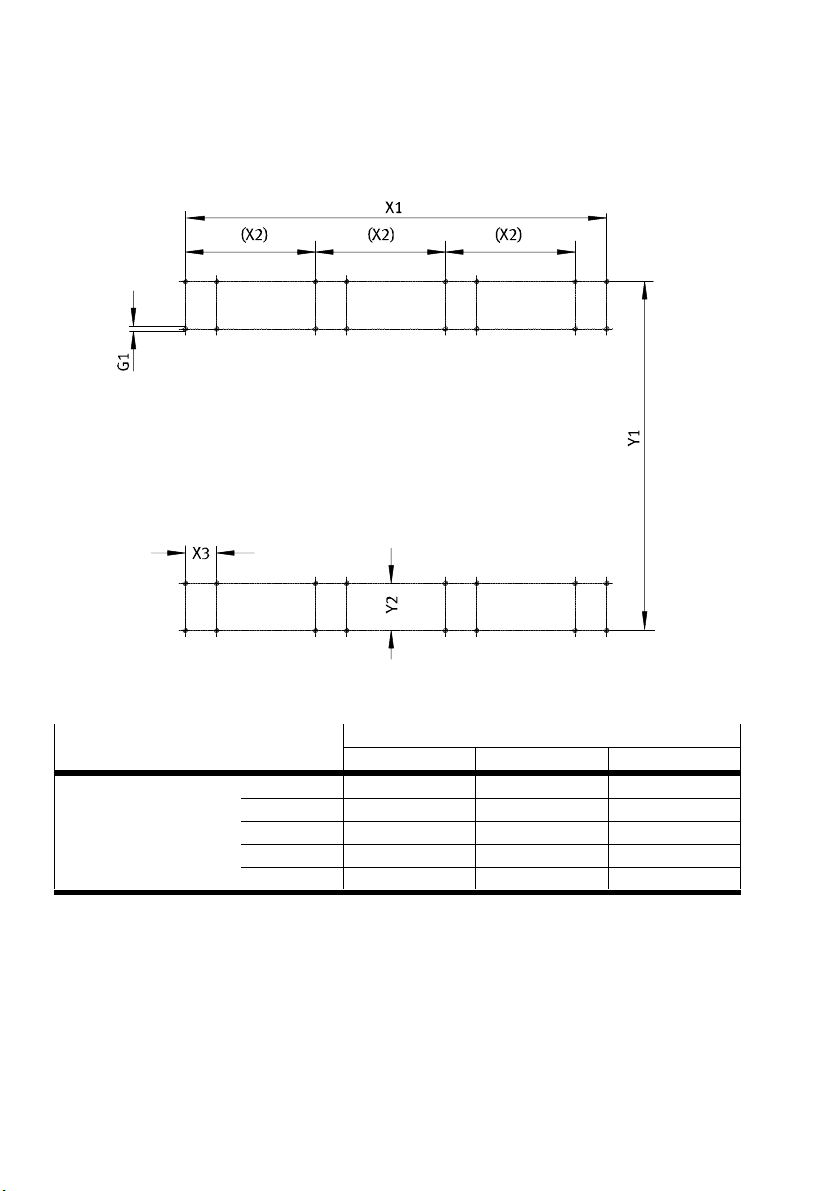
5.1.3 Preparation of the mounting surface
For mounting kit without adjustment possibility
Ensure mounting surface is flat and horizontal:
The required flatness depends on the size of the handling system.
Flatness Y1 [mm]
3 1000 1001 … 2000 2001 … 3000
X1 [mm] 3 1000 0.1 0.2 0.3
1001 … 2000 0.2 0.4 0.6
2001 … 3000 0.3 0.6 0.9
3001 … 4000 0.4 0.8 1.2
4001 … 5000 0.5 1.0 1.5
40 Festo – GDCP-YXC-EN – 1502NH – English
Page 41
5 Installation of the planar surface gantries and the three-dimensional gantries
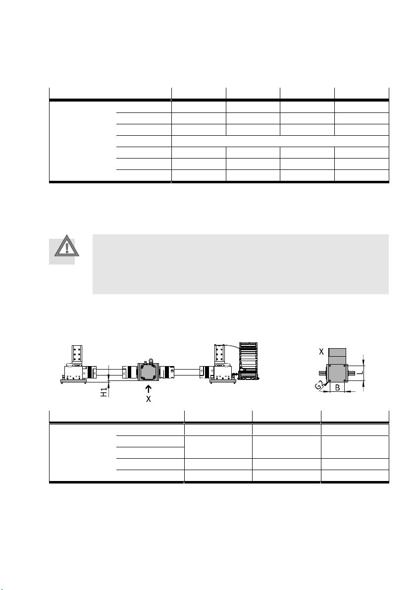
Prepare mounting option on mounting surface.
Mounting kit is movable. If required, change dimension X2.
EHMX-EGC-
Dimensions [mm] Y1
1)
50 80 120 185
By + 108 By + 182 By + 280 By + 386
Y2 60 100 160 200
2)
X1
X2
3)
Hx + 51 Hx + 146 Hx + 224 Hx + 310
(X1 – X3) / [(n / 2) – 1]
X3 50 68 106 106
G1 M3 M5 M8 M8
Depth of thread 6 8 13 13
1) By = width in Y-direction (è 1.1 Technical data)
2) Hx = stroke in X-direction (è 1.1 Technical data)
3) n = total number of mounting components for both X-axes (è 5.1.2 Number n of mounting components)
For X-module with motor position in the middle:
Caution
Unfastened motor in the middle turns with the shaft.
Injury due to impacts or pinching. Damage to the product.
Place motor outside the movement range.
Fasten motor sufficiently.
Prepare mounting option.
The drive shafts of the gear units and the hollow shafts must be sufficiently aligned
(è 5.5.2 Mounting of the connecting shaft).
EHMX-EGC-...-M 80 120 185
Dimensions [mm] H1 – 0.5 7.6 26.5
L 70 100 110
B
G2 M8 M10 M10
Depth of thread G2 14 16 20
Festo – GDCP-YXC-EN – 1502NH – English 41
Page 42
5 Installation of the planar surface gantries and the three-dimensional gantries
For adjusting kit
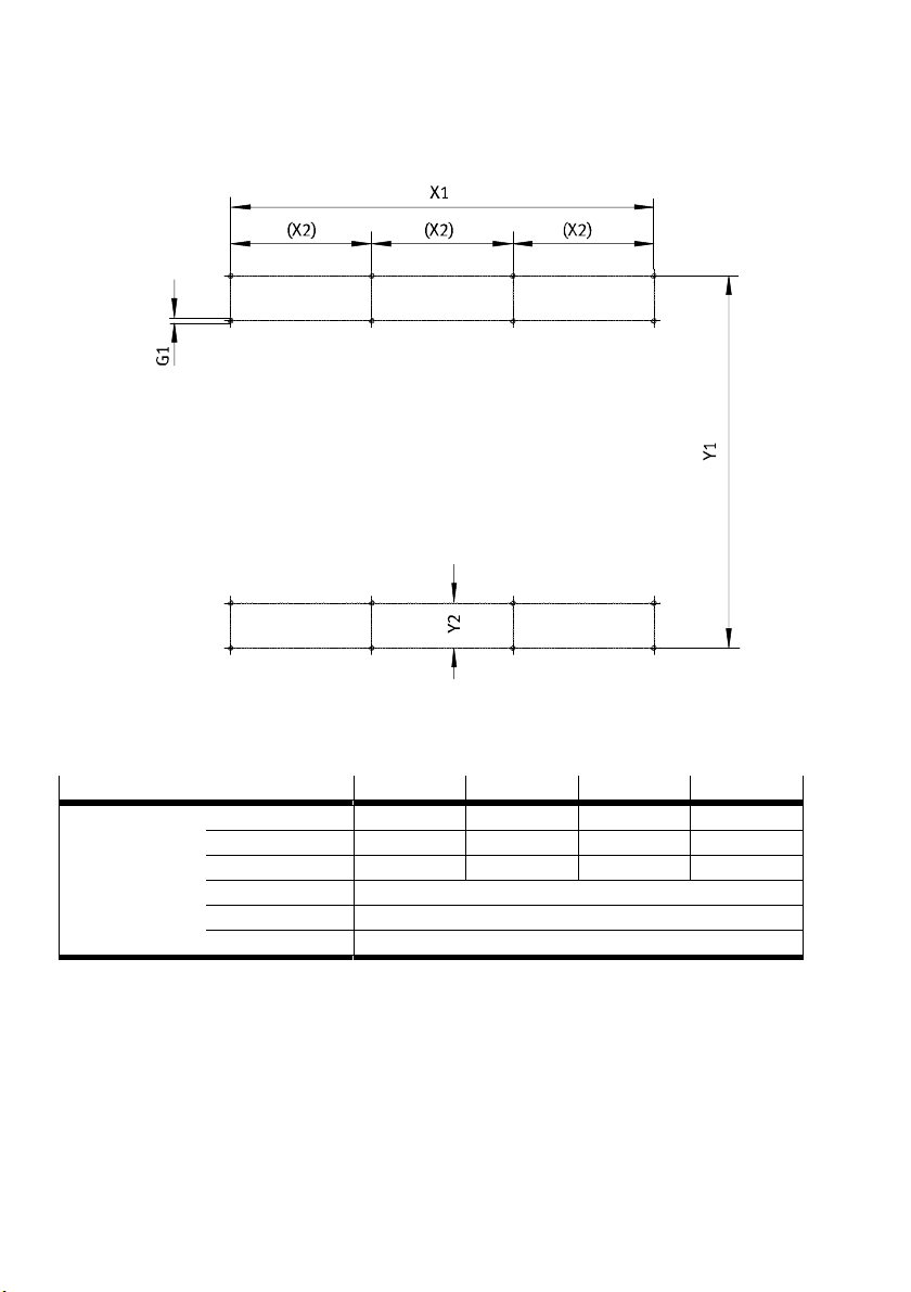
Ensure flat and horizontal mounting surface: flatness 2 mm
Prepare mounting option on mounting surface.
Adjusting kit is movable. If required, change dimension X2.
EHMX-EGC- 50 80 120 185
Dimensions [mm] Y1
1)
By + 110 By + 186 By + 260 By + 395
Y2 62 104 140 209
2)
X1
X2
3)
Hx + 1 Hx + 78 Hx + 118 Hx + 204
(X1) / [(n / 2) – 1]
G1 M8
Depth of thread G1 13
1) By = width in Y-direction (è 1.1 Technical data)
2) Hx = stroke in X-direction (è 1.1 Technical data)
3) n = total number of mounting components for both X-axes (è 5.1.2 Number n of mounting components)
42 Festo – GDCP-YXC-EN – 1502NH – English
Page 43
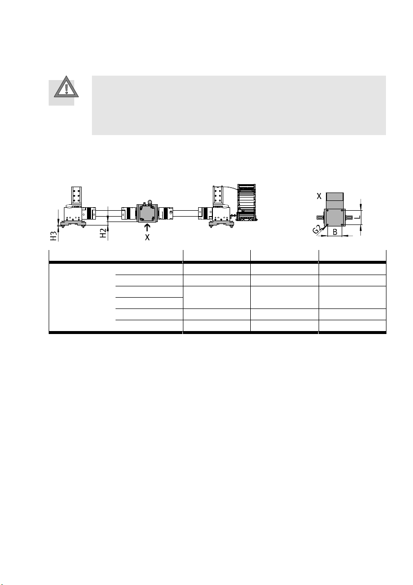
5 Installation of the planar surface gantries and the three-dimensional gantries
For X-module with motor position in the middle:
Caution
Unfastened motor in the middle turns with the shaft.
Injury due to impacts or pinching. Damage to the product.
Place motor outside the movement range.
Fasten motor sufficiently.
Prepare adjustable mounting option.
The drive shafts of the gear units and the hollow shafts must be sufficiently aligned
(è 5.5.2 Mounting of the connecting shaft).
EHMX-EGC-...-M 80 120 185
Dimensions [mm] H2 18.5 20.6 39.5
H3 8 ± 3 8 ± 3 8 ± 3
L 70 100 110
B
G2 M8 M10 M10
Depth of thread G2 14 16 20
Festo – GDCP-YXC-EN – 1502NH – English 43
Page 44
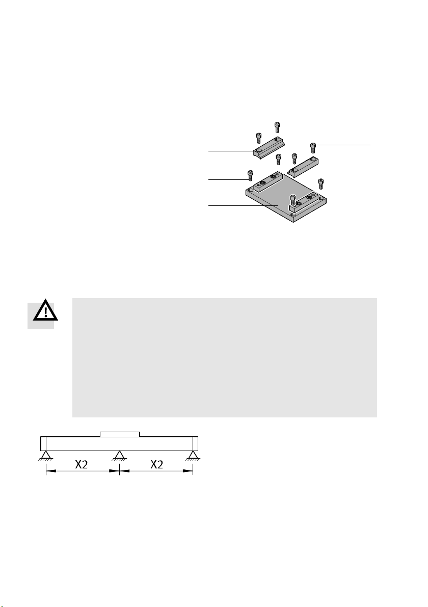
5 Installation of the planar surface gantries and the three-dimensional gantries
5.2 Mounting components
5.2.1 Mounting kit without adjustment possibility
Structure
1 Lower part
2 Screw, lower part
3 Upper part
4 Screw, upper part
1) Screw and tightening torque are designed for mounting on steel.
Requirements
– Number n of mounting components is known (è 5.1.2 Number n of mounting components).
– Mounting surface is prepared (è 5.1.3 Preparation of the mounting surface).
Mounting
Warning
Incorrect mounting. Entire product moves uncontrollably.
Injury due to impacts or pinching. Damage to the product.
Use screws 2 with strength class of at least 8.8.
Select screws 2 suitable for the installation situation.
Mount product free of distortion.
Use only the mounting kits supplied.
Secure threaded connections.
Make sure the mounting surface is sufficiently strong to absorb the maximum
forces.
(1x)
1)
(2x)
(4x)
3
(4x)
2
1
4
The mounting kits are pre-mounted to the
X-axes.
Check number n and support spacing X2.
Place X-axes
(è 5.3.1 Installation YXCF/YXCR).
44 Festo – GDCP-YXC-EN – 1502NH – English
Page 45
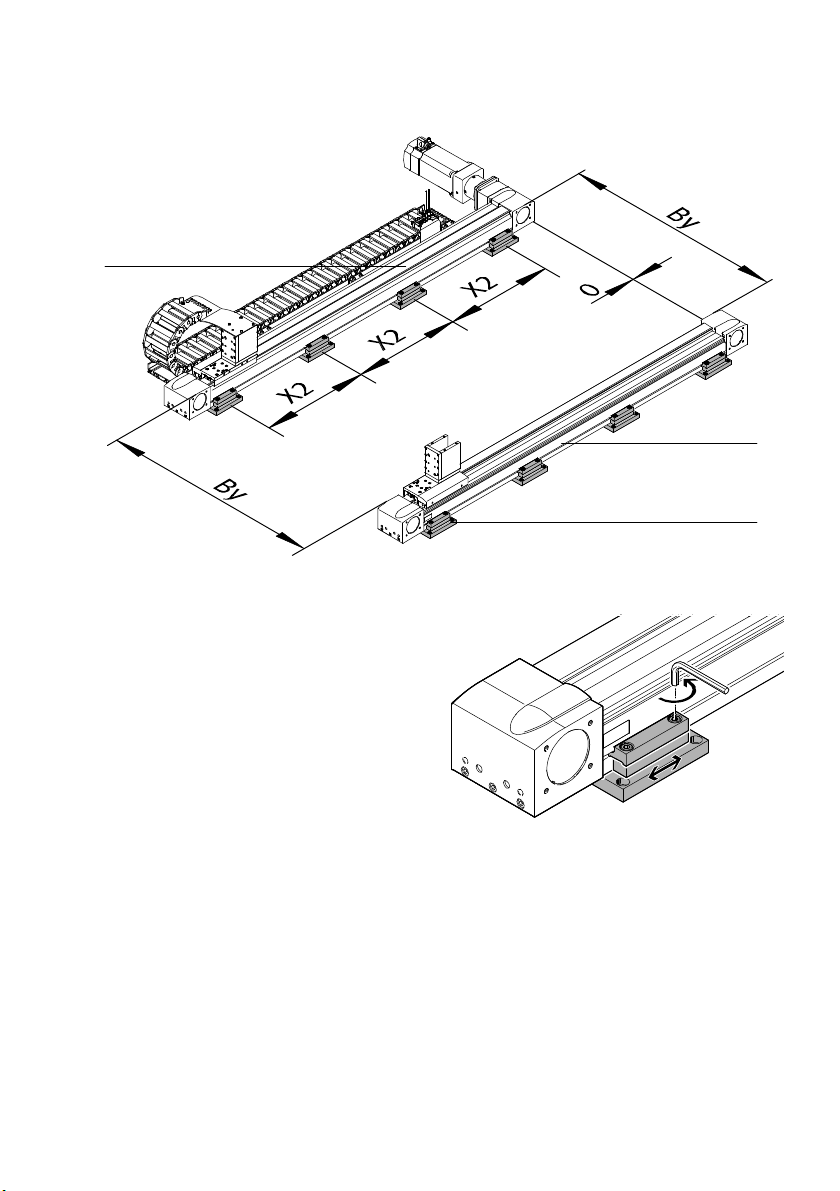
5 Installation of the planar surface gantries and the three-dimensional gantries
1
1 X-axis 2 Mounting kit
1. Unscrew the screws of the upper part slightly.
2. Position mounting kit.
1
2
Festo – GDCP-YXC-EN – 1502NH – English 45
Page 46
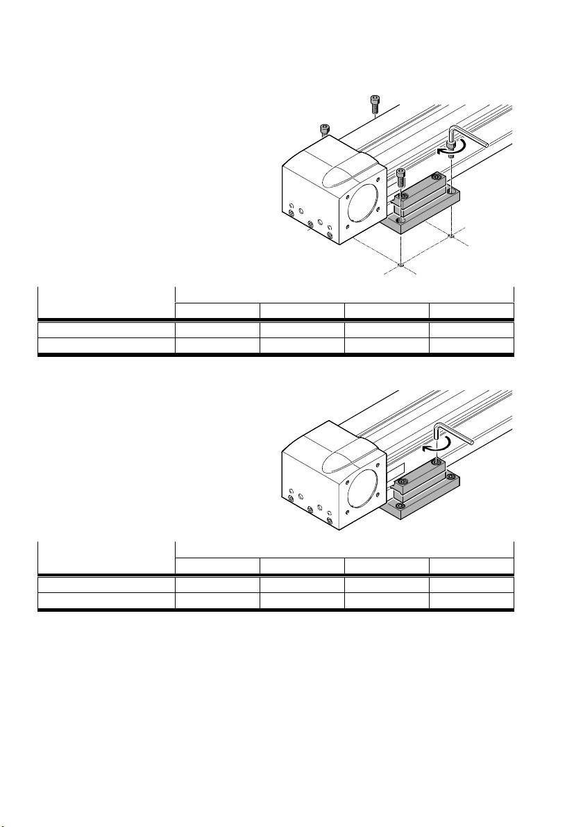
5 Installation of the planar surface gantries and the three-dimensional gantries
3. Fasten lower part to the mounting surface
1)
with suitable screws
.
4. Align X-axes exactly with each other
(è 5.3.1 Installation YXCF/YXCR).
Screw size and tightening
torque
EHMX-EGC50 80 120 185
M3x10 M5x12 M8x20 M8x20
[Nm] 1.2 5.9 20 20
1) Accompanying screws and tightening torque are designed for mounting on steel.
5. Evenly tighten screws of the upper part.
Screw size and tightening
torque
EHMX-EGC50 80 120 185
M3x7 M5x16 M8x20 M8x20
[Nm] 1.2 5.9 20 20
46 Festo – GDCP-YXC-EN – 1502NH – English
Page 47
5 Installation of the planar surface gantries and the three-dimensional gantries
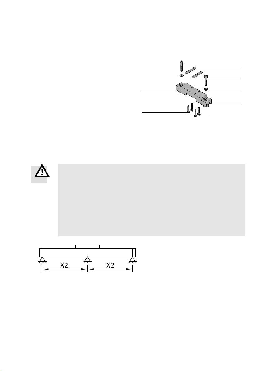
5.2.2 Adjusting kit
Structure
1 Adjusting plate
2 Slot nut
3 Screw
1)
4 Washer
5 Square nut
6 Adjusting bolt
7 Screw
1) Screw and tightening torque are designed for mounting on steel.
(1x)
(4x)
(2x)
(2x)
(2x)
(2x)
(4x)
1
7
6
Requirements
– Number n of mounting components is known (è 5.1.2 Number n of mounting components).
– Mounting surface is prepared (è 5.1.3 Preparation of the mounting surface).
Mounting
Warning
Incorrect mounting. Entire product moves uncontrollably.
Injury due to impacts or pinching. Damage to the product.
Use screws 3 with strength class of at least 8.8.
Select screws 3 suitable for the installation situation.
Mount product free of distortion.
Use only the mounting kits supplied.
Secure threaded connections.
Make sure the mounting surface is sufficiently strong to absorb the maximum
forces.
2
3
4
5
The adjusting kits are pre-mounted to the
X-axes.
Check number n and support spacing X2.
Place X-axes (è 5.3.1 Installation YXCF/YXCR)
Festo – GDCP-YXC-EN – 1502NH – English 47
Page 48
5 Installation of the planar surface gantries and the three-dimensional gantries
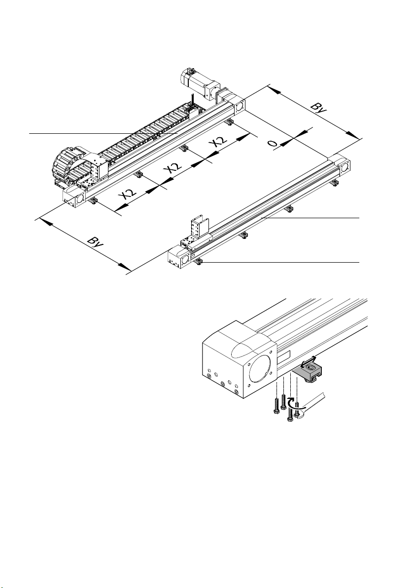
1
1 X-axis 2 Adjusting kit
1. Slightly unscrew the screws on the underside.
2. Position adjusting plate.
1
2
48 Festo – GDCP-YXC-EN – 1502NH – English
Page 49
5 Installation of the planar surface gantries and the three-dimensional gantries
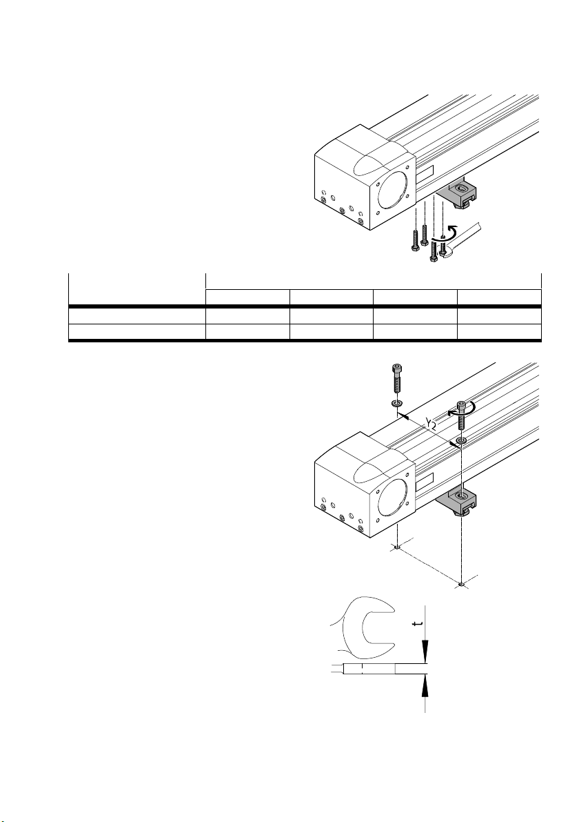
3. Tighten screws on the underside.
Screw size and tightening
torque
EHMX-EGC50 80 120 185
M3x16 M5x25 M6x30 M6x30
[Nm] 1.2 5.9 9.9 9.9
4. Place washers under screws.
5. Place screws in the centre of the elongated
hole.
6. Lightly clamp the adjusting plate to the
mounting surface with the screws.
7. Use spanner with t 5 mm.
If t 5 mm, the maximum height compensator is
smaller by the difference (t − 5) mm.
Festo – GDCP-YXC-EN – 1502NH – English 49
Page 50
5 Installation of the planar surface gantries and the three-dimensional gantries
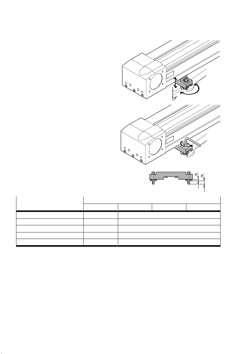
8. Align X-axes exactly with each other
(è 5.3.1 Installation YXCF/YXCR).
9. Screw adjusting bolts in or out
(maximum height compensator è Table).
10.Tighten screws. Apply counter pressure to the
adjusting bolt.
Check:
– The adjusting bolt has not twisted.
– The alignment has been maintained.
11.Make sure there is sufficient screw-in depth m
of the screw (è Table).
Screw size and tightening
1)
torque
EHMX-EGC50 80 120 185
M5x30 M8x40
M
A
[Nm] 5.9 34
m [mm] 12 15
h [mm] 7 ± 2 8 ± 3
Max. height compensator [mm] 4 6
1) Screw, tightening torque and screw-in depth are designed for mounting on steel.
50 Festo – GDCP-YXC-EN – 1502NH – English
Page 51
5 Installation of the planar surface gantries and the three-dimensional gantries
5.3 Completely mounted handling system
5.3.1 Installation YXCF/YXCR
Structure
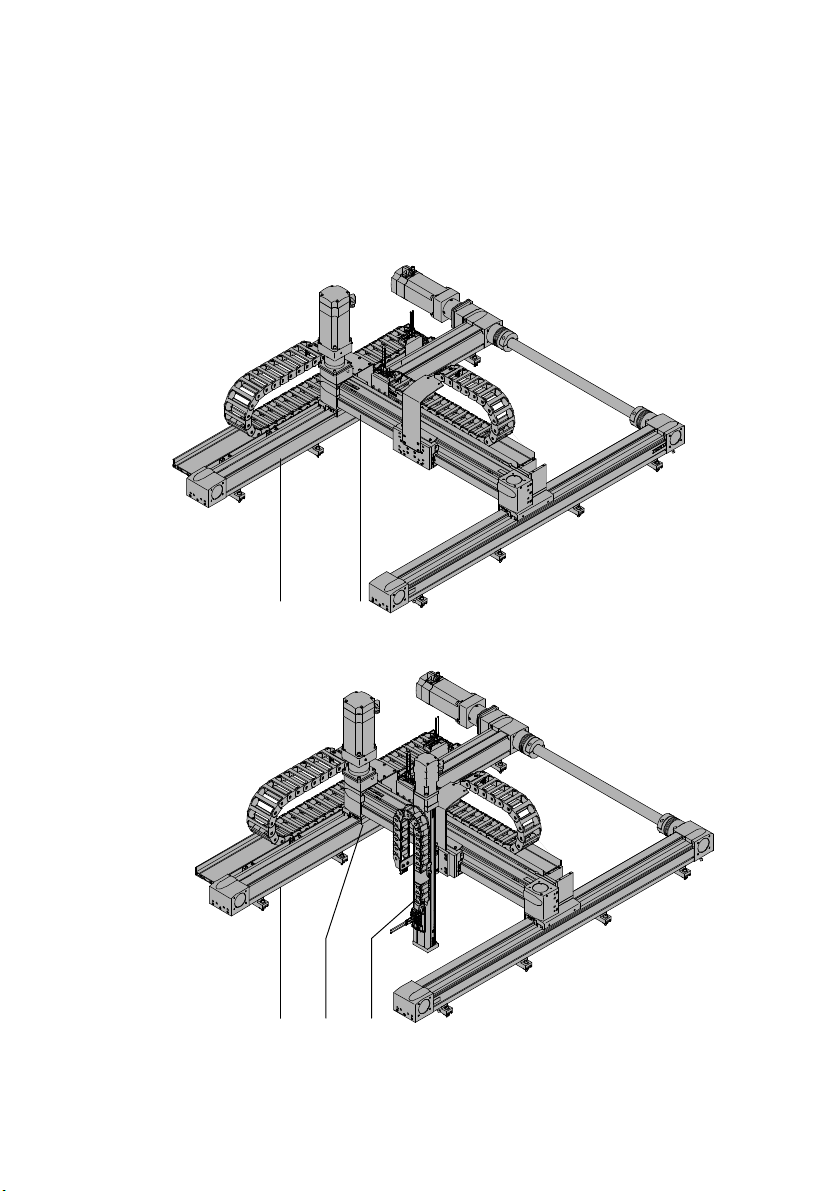
Planar surface gantry YXCF
1 2
Three-dimensional gantry YXCR
312
1 X-module
2 Y-module
Festo – GDCP-YXC-EN – 1502NH – English 51
3 Z-module
Page 52
5 Installation of the planar surface gantries and the three-dimensional gantries
Requirements
– Mounting surface is prepared (è 4.1.3 Preparation of the mounting surface).
– Transport protection in the shipping crate is removed
(è 2.4.1 Securing in the transport protection crate ).
– Transport protection for lifting is mounted (è 2.4.2 Securing when lifting ).
– Function of the mounting components is known
(è 5.2.1 Mounting kit without adjustment possibility/5.2.2 Adjusting kit).
Installation
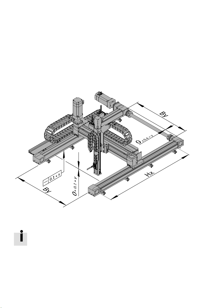
1. Place handling system slowly and carefully onto the prepared mounting surface.
x = Hx/1000 y = By/1000
2. Lightly clamp X-axis with energy chain to the mounting surface.
Straightness can be adjusted with adjusting kits. For mounting kits without adjustment
possibilities, the mounting surface must be correspondingly flat.
3. Align X-axis with energy chain to the underside.
Check: straightness 0.1 mm × (Hx/1000)
4. Fasten X-axis with energy chain to the mounting surface.
5. Align second X-axis flush with the mounted X-axis.
– Length offset ± 0.4 mm × (By/1000)
6. Lightly clamp second X-axis to the mounting surface.
52 Festo – GDCP-YXC-EN – 1502NH – English
Page 53
5 Installation of the planar surface gantries and the three-dimensional gantries
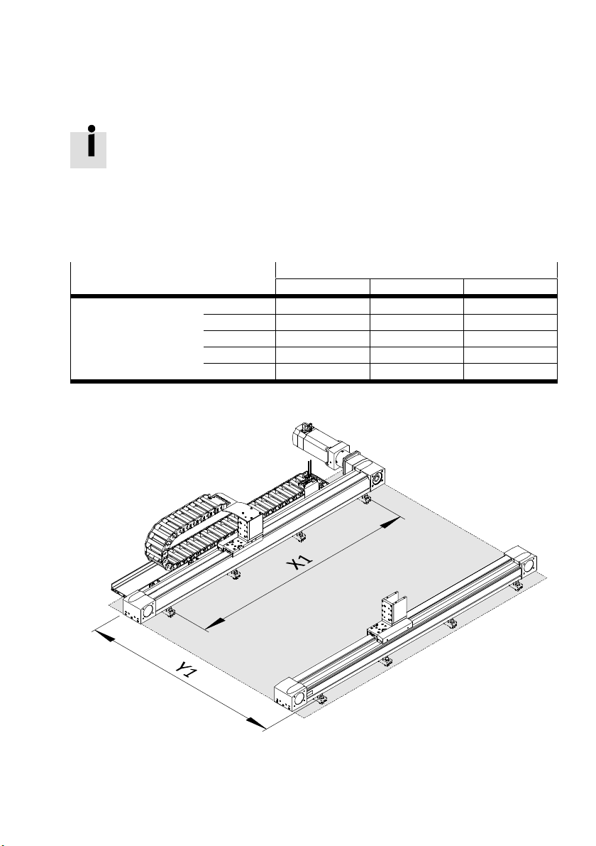
7. Align underside of the second X-axis parallel in height to the mounted X-axis.
Check: height offset + 0.1 mm × (By/1000)
The height offset can be adjusted with adjusting kits. For mounting kits without adjust
ment possibilities, the mounting surface must be correspondingly flat.
8. Fasten second X-axis to the mounting surface.
9. Check alignment.
Check:
– The undersides of the X-axes must lie entirely in a theoretical plane with the required flatness.
The required flatness depends on the size.
Flatness Y1
1)
[mm]
3 1000 1001 … 2000 2001 … 3000
1)
X1
[mm] 3 1000 0.1 0.2 0.3
1001 … 2000 0.2 0.4 0.6
2001 … 3000 0.3 0.6 0.9
3001 … 4000 0.4 0.8 1.2
4001 … 5000 0.5 1.0 1.5
1) Calculation of the dimensions Y1 and X1, depending on the mounting component (è 5.1.3 Preparation of the mounting surface)
Festo – GDCP-YXC-EN – 1502NH – English 53
Page 54
5 Installation of the planar surface gantries and the three-dimensional gantries
The height offset can be adjusted with adjusting kits. For mounting kits without adjust
ment possibilities, the mounting surface must be correspondingly flat.
Note
Incorrect mounting can cause material damage and malfunction.
Collision between Z-module and transport protection aids.
Remove all transport protection aids (è 2.4 Transport protection aids ).
To take tension out of the system:
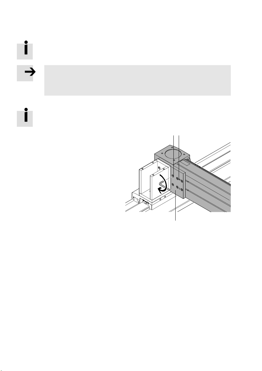
The bolts define the position of the Y-module in the Z-direction.
Have the premounted bolt 1 fastened. Do not unscrew it!
On one side of the Y-module:
10.Unscrew screws 3 at the adapter
13
– The adapter is movable.
1 Bolt (1x)
2 Adapter (1x)
3 Screw (6x ... 8x)
2
11.The slides of the X-module are blocked with motor position left/right. To be able to move the slides
for alignment:
– For motor with brake.
Remove motor (è 5.6 Motor with brake (EMMS-...-RSB/RMB).
– For motor without brake
Remove jumper at the end of the respective motor cable.
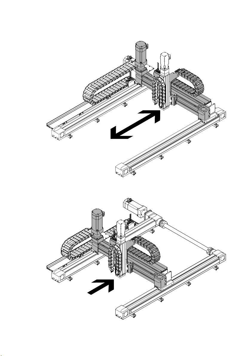
12.Move Y-module back and forth on the X-module one time.
54 Festo – GDCP-YXC-EN – 1502NH – English
Page 55
5 Installation of the planar surface gantries and the three-dimensional gantries
13.Move Y-module into the middle of the X-axes.
Festo – GDCP-YXC-EN – 1502NH – English 55
Page 56
5 Installation of the planar surface gantries and the three-dimensional gantries
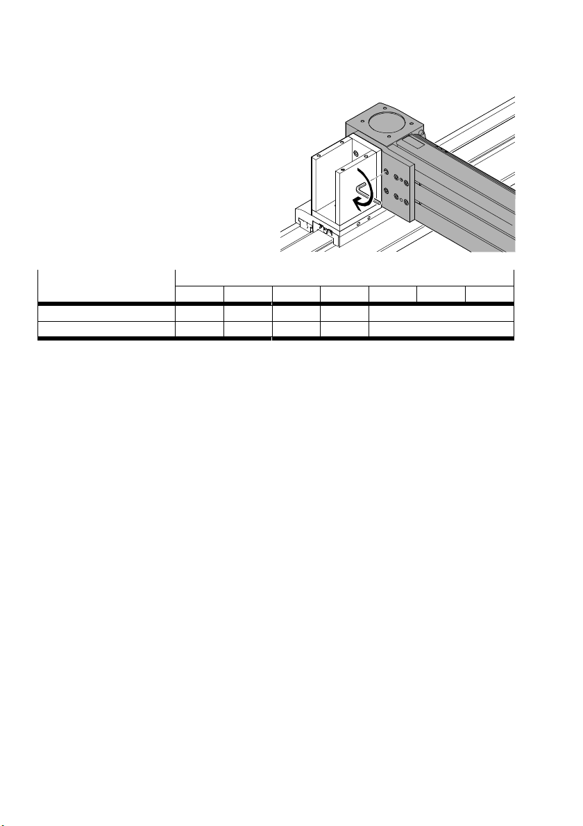
14.Evenly tighten screws.
Screw size and tightening
torque
EHMY-EGC50 80 120 125 160 185 220
M3x8 M5x12 M6x16 M5x12 M6x16
[Nm] 1.7 8.3 14 8.3 14
15.Check mechanical alignment and structure (è 5.4 Check the alignment and structure).
56 Festo – GDCP-YXC-EN – 1502NH – English
Page 57
5 Installation of the planar surface gantries and the three-dimensional gantries
5.4 Check the alignment and structure
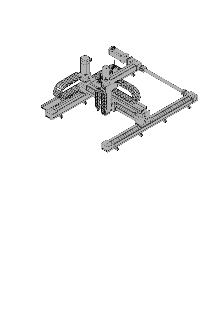
1. Check mechanical alignment and structure.
Check:
– All components are fastened (exception: motor with brake).
– The Y- and Z-axes can be moved by hand. Difficulty of movement, at individual points or con
stantly, due to misalignment, offset or tension, cannot be felt. Align handling system again, if
necessary.
For motor with brake:
2. Mount motor (è 5.6 Motor with brake (EMMS-...-RSB/RMB)/(è 5.5 Connecting shaft).
3. Execute test run (è 8 Commissioning).
Festo – GDCP-YXC-EN – 1502NH – English 57
Page 58
5 Installation of the planar surface gantries and the three-dimensional gantries
5.5 Connecting shaft
5.5.1 Structure
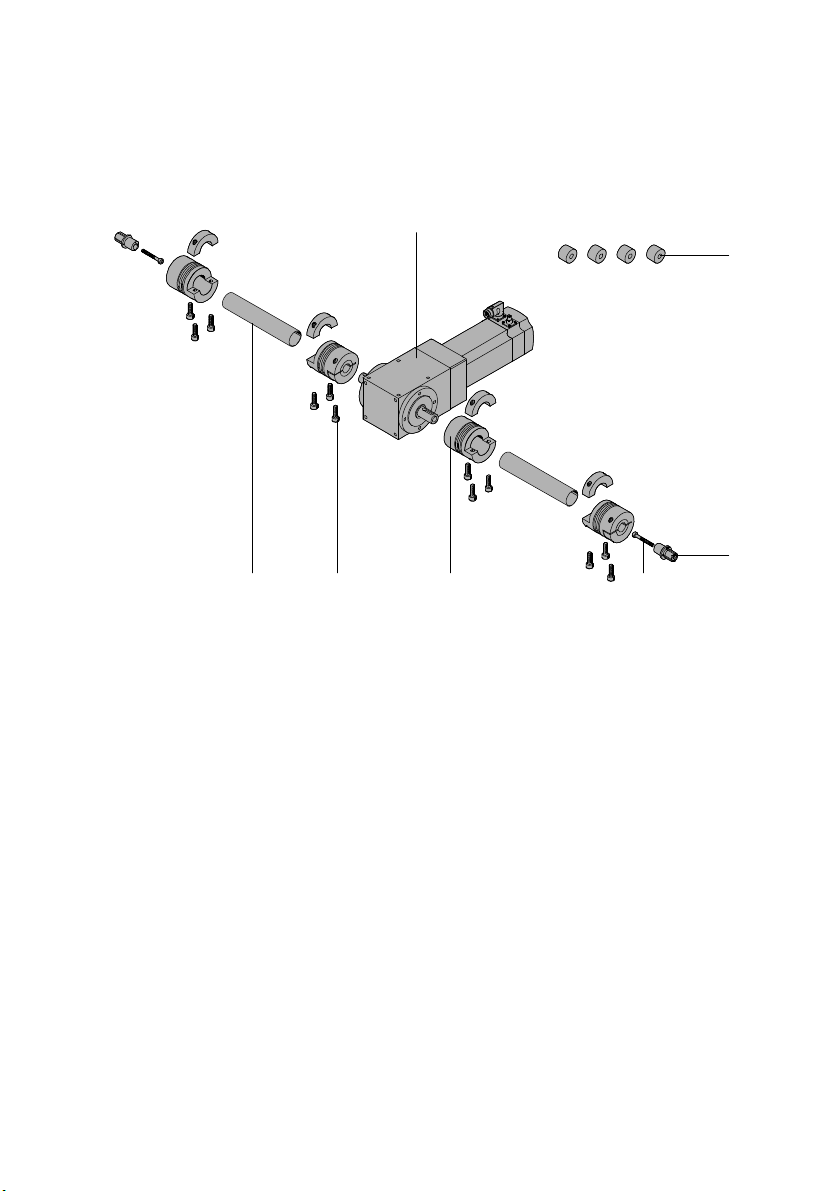
For motor position in the middle
12 3 4
1 Connecting tube (2x)
2 Screw (12x)
3 Coupling (4x)
4 Clamping screw (2x)
1) Plug only for size 185
5 Drive shaft (2x)
6 Plug (4x)
1)
7 Gear unit/motor
67
5
5.5.2 Mounting of the connecting shaft
Requirements
– X-axes of the X-module are mounted and aligned
(è 5.3.1 Installation YXCF/YXCR).
– Y-module is mounted and aligned
(è 5.3.1 Installation YXCF/YXCR).
– Hollow shafts are aligned.
58 Festo – GDCP-YXC-EN – 1502NH – English
Page 59
5 Installation of the planar surface gantries and the three-dimensional gantries
Note
Incorrect mounting can cause material damage and malfunction.
Collision with Y-module or Z-module if the connecting shaft is mounted to the wrong
side.
Mount connecting shaft only to the drive side (è 5.3.1 Installation YXCF/YXCR).
Couplings slide if the contact surfaces are not dry and free of grease.
Clean contact surfaces on the following components:
– Connecting tube
– Couplings
– Drive shafts (leave expanding mandrel cone greased on the inside).
– Hollow shafts on the X-axes
– Drive shafts on the gear unit
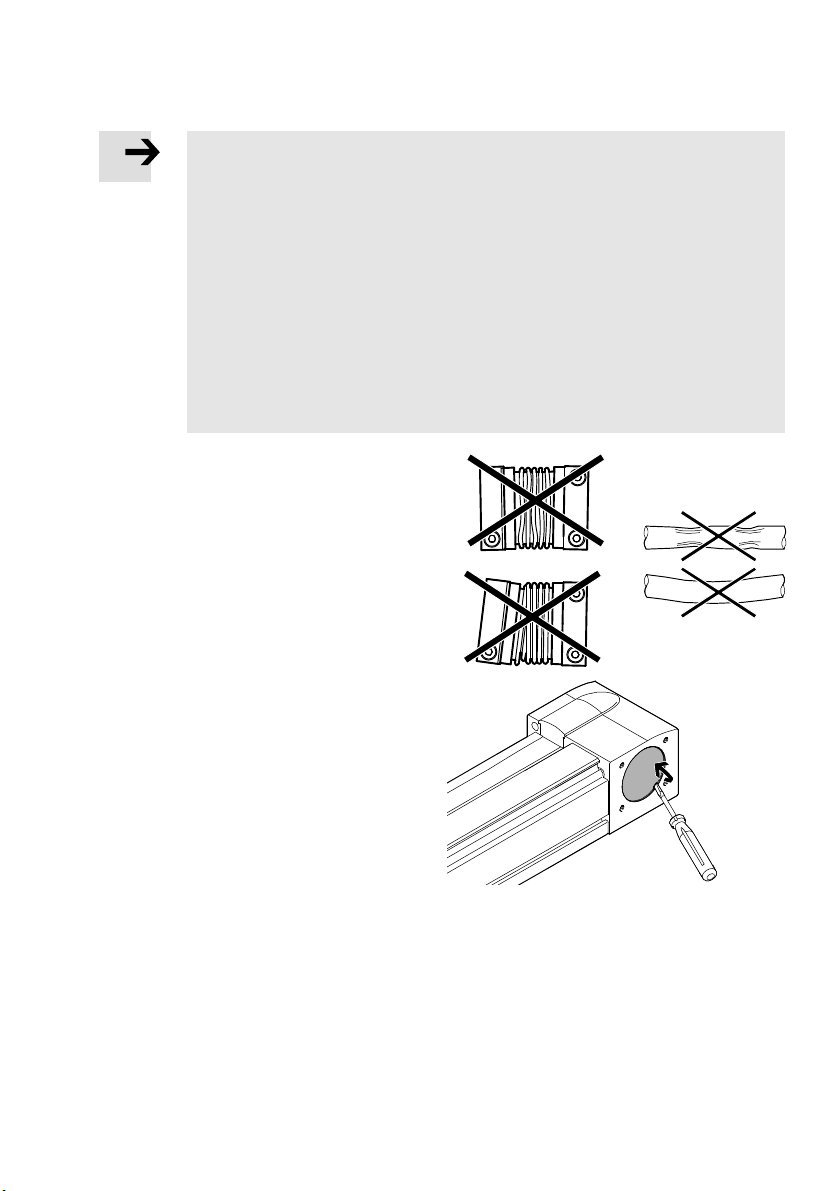
Check connecting tube and couplings for
1.
excellent condition.
Check: no kinks, dents, deflections.
2. Insert a screwdriver into the cut-out.
3. Lift off covers at the hollow shafts.
Festo – GDCP-YXC-EN – 1502NH – English 59
Page 60
5 Installation of the planar surface gantries and the three-dimensional gantries
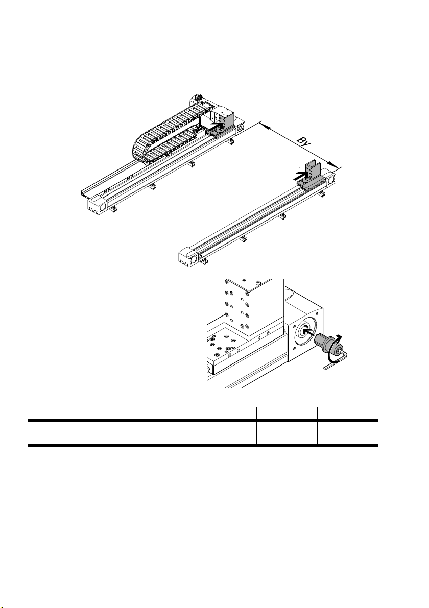
4. Push slide into the corresponding end position:
– The hollow shafts no longer turn when the clamping screws are tightened.
5. Push the drive shaft with the expanding
mandrel as far as possible into the hollow
shaft.
6. Tighten clamping screws.
Screw size and tightening
torque
EHMX-EGC50 80 120 185
M3 M5 M8 M10
[Nm] 1 7 14 60
60 Festo – GDCP-YXC-EN – 1502NH – English
Page 61
5 Installation of the planar surface gantries and the three-dimensional gantries
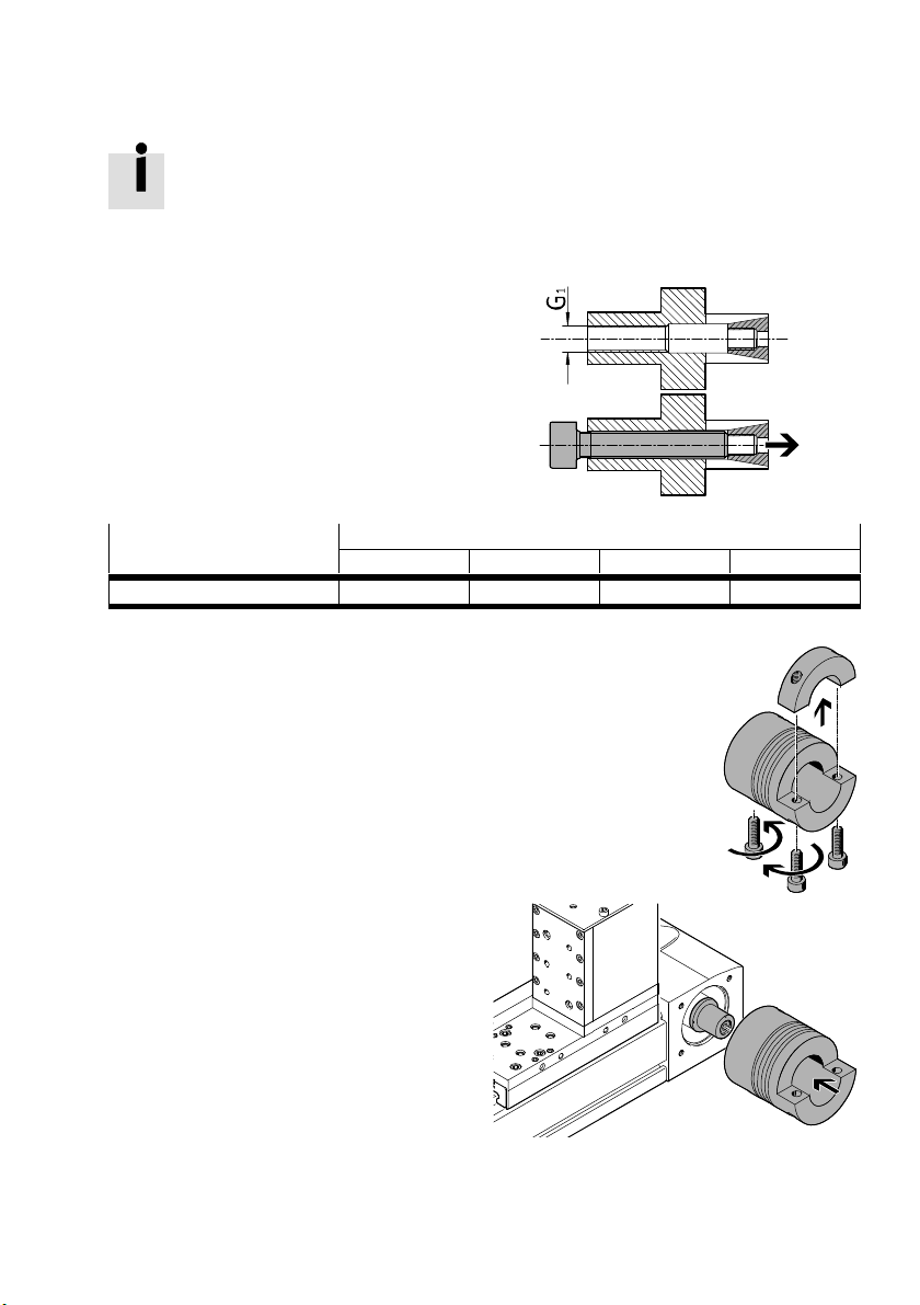
If the expanding mandrel cone is stuck, mounting is not possible. The drive shaft has a
forcing thread G
.
1
Turn screw into the thread G1.
Push out expanding mandrel cone.
Thread size EHMX-EGC-
50 80 120 185
G1 M4 M6 M10 M12
7. Unscrew the screws.
8. Lift off half-shell.
9. Push couplings as far as possible onto the
drive shafts.
Festo – GDCP-YXC-EN – 1502NH – English 61
Page 62
5 Installation of the planar surface gantries and the three-dimensional gantries
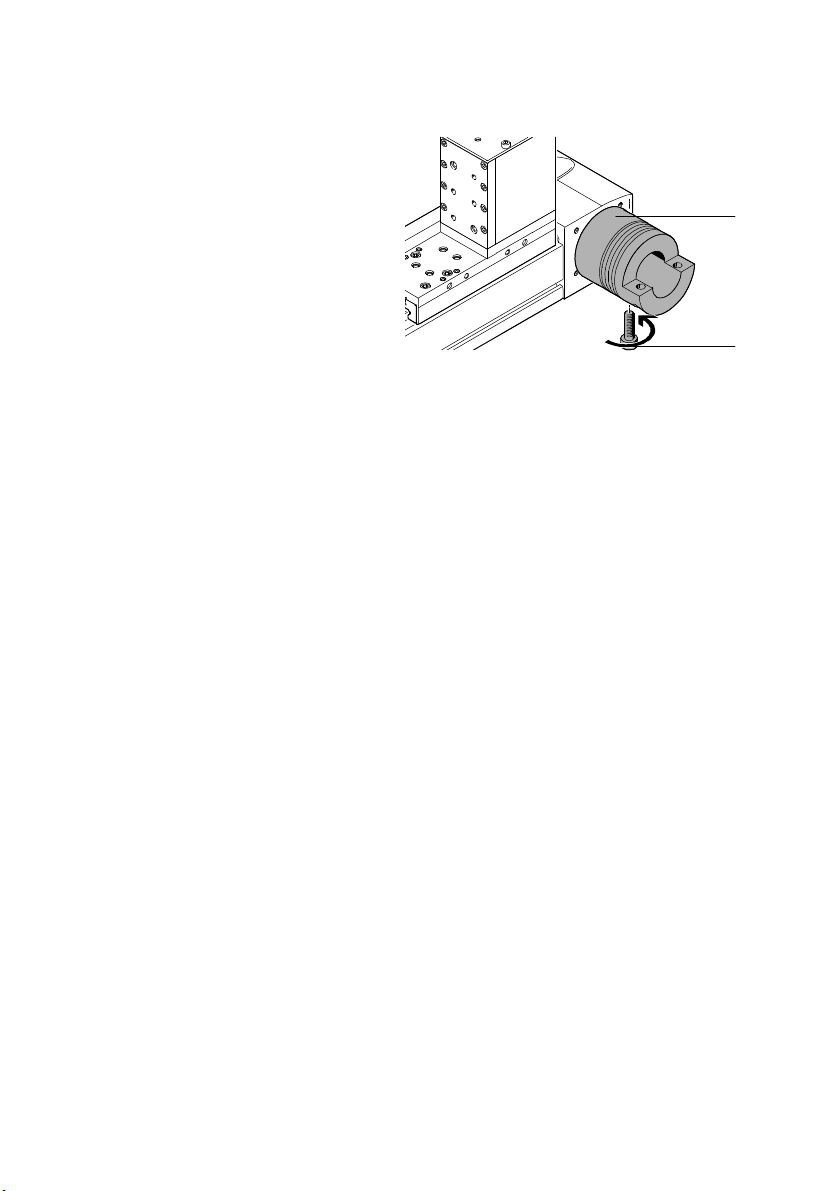
10.Tighten screw slightly:
– All couplings are fixed.
3
2
62 Festo – GDCP-YXC-EN – 1502NH – English
Page 63
5 Installation of the planar surface gantries and the three-dimensional gantries
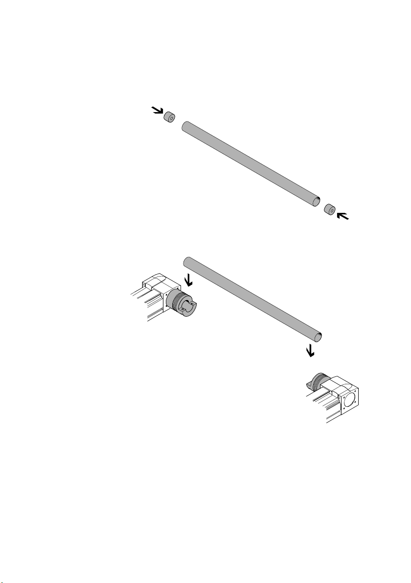
For motor position left/right
Only for EHMX 185
1. Push the plugs into the connecting tube.
2. Place connecting tube into the couplings.
3. Continue with point 6. (è Page 65).
Festo – GDCP-YXC-EN – 1502NH – English 63
Page 64
5 Installation of the planar surface gantries and the three-dimensional gantries
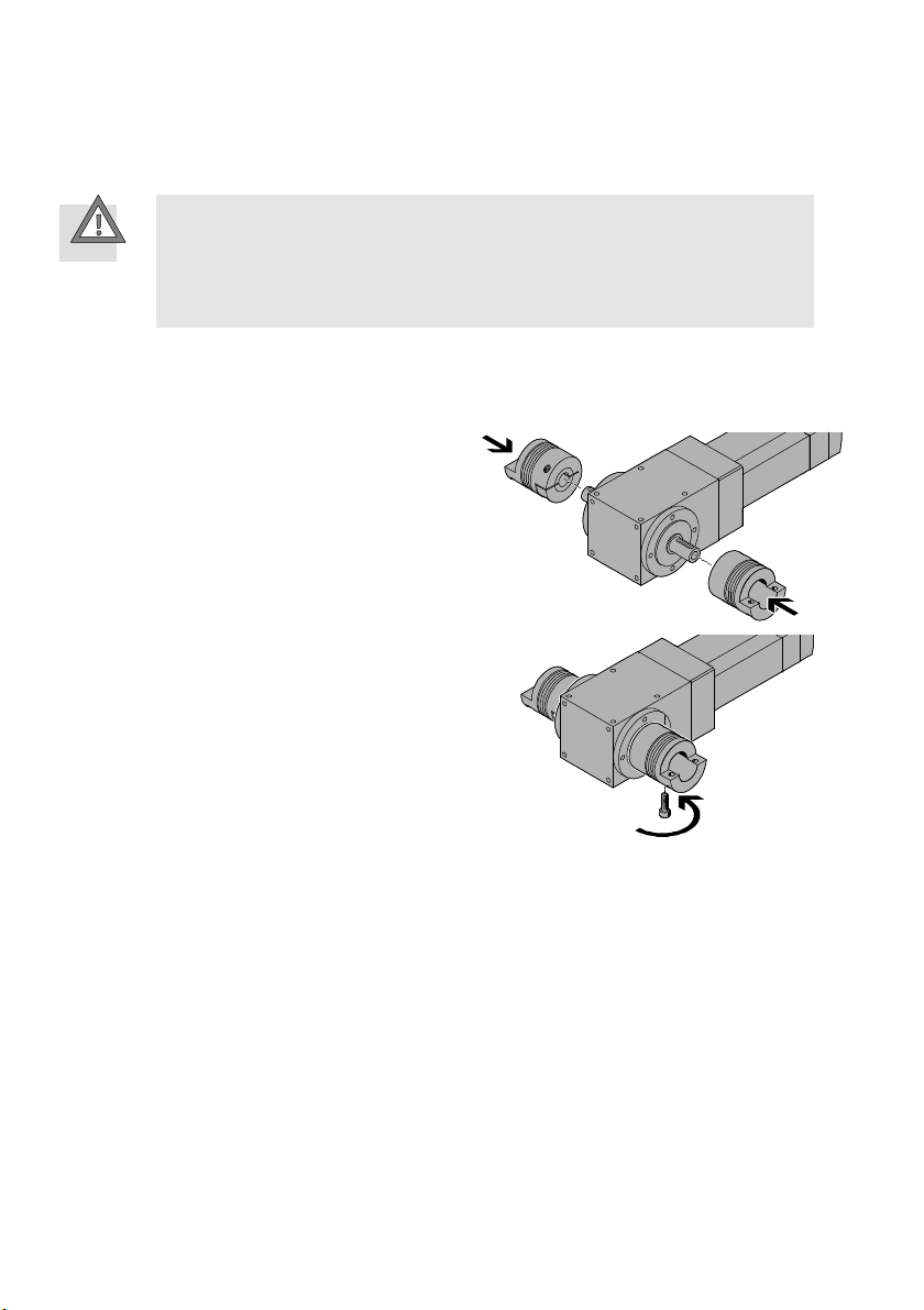
For motor position in the middle
Otherwise with point 6. (è Page 65).
Caution
Unfastened motor in the middle turns with the connecting shaft.
Injury due to impacts or pinching. Damage to the product.
Place motor outside the movement range.
Fasten motor sufficiently (è 5.1.3 Preparation of the mounting surface).
If feather keys are pressed into the drive shaft of the gear unit:
1. Remove feather keys.
2. Place motor outside the movement range.
3. Push couplings as far as possible onto the
drive shafts.
4. Tighten the screws lightly.
Check: The couplings are fixed on both sides.
64 Festo – GDCP-YXC-EN – 1502NH – English
Page 65
5 Installation of the planar surface gantries and the three-dimensional gantries
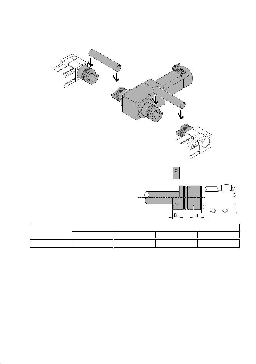
5. Place connecting tube into the coupling.
6. Unscrew the coupling screws slightly.
7. Align couplings in the middle.
8. Observe push-in depth B of the shaft.
Push-in depth EHMX-EGC-
50 80 120 185
B [mm] 10.2 13.1 21.6 26
Festo – GDCP-YXC-EN – 1502NH – English 65
Page 66
5 Installation of the planar surface gantries and the three-dimensional gantries
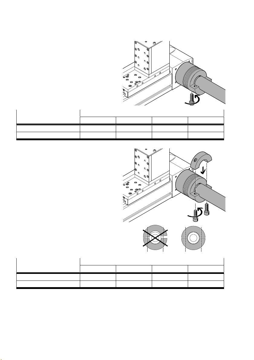
9. Tighten screws.
Screw size and tightening
torque
EHMX-EGC50 80 120 185
M4x16 M5x18 M10x30 M12x40
[Nm] 2.9 8 50 120
10.Place half shells. Tighten screws only lightly at
first.
11.Clamp connecting tube to the half shell evenly
and symmetrically.
12.Tighten screws.
Screw size and tightening
torque
EHMX-EGC50 80 120 185
M4x16 M5x18 M10x30 M12x40
[Nm] 2.9 8 50 120
66 Festo – GDCP-YXC-EN – 1502NH – English
Page 67
5 Installation of the planar surface gantries and the three-dimensional gantries
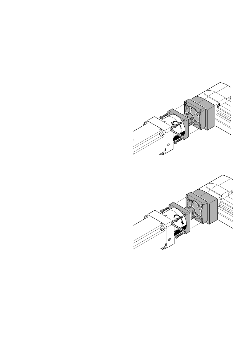
5.6 Motor with brake (EMMS-...-RSB/RMB)
Dismantling is required only for a motor with brake in order to push the slide for alignment of the sys
tem. A motor without brake can remain mounted.
5.6.1 Dismantling
For motor position left/right, the motor is located on an X-axis.
Unscrew screws.
Remove motor from the X-axis.
5.6.2 Mounting
Push motor onto the X-axis.
Check: correct position of the coupling hubs in
relation to each other.
Connect motor flanges together.
Tightening torques
M4: 3 Nm
M6: 10 Nm
M8: 18 Nm
Festo – GDCP-YXC-EN – 1502NH – English 67
Page 68

6 Attachment components
6 Attachment components
6.1 Mounting to the Y-module
For single-axis system and planar surface gantry:
Mount attachment components to the Y-module. The corresponding interface is taken from the CAD
model (è 1.1 Technical data).
Connect attachment components to the earth potential (è 7.2 Earthing).
6.2 Mounting to the Z-module
For linear gantry and three-dimensional gantry:
Mount attachment components to the Z-module. The corresponding interface is taken from the CAD
model (è 1.1 Technical data).
Connect attachment components to the earth potential (è 7.2 Earthing).
68 Festo – GDCP-YXC-EN – 1502NH – English
Page 69
7 Installation
7 Installation
7.1 Safety instructions
Note
A prerequisite for the electrical installation is a completely mounted and aligned hand
ling system.
Note
The power supply is not switched off.
Damage to the product from incorrect handling.
Never pull the plug connectors and electrical interfaces when powered.
Never connect the plug connectors and electrical interfaces when powered.
Observe the handling specifications for electrostatically sensitive devices.
Warning
Faulty installation of electrical components.
Injury due to electric shock. Damage to the product.
Installation may only be performed by qualified specialized personnel who are familiar
with:
– installation and operation of electrical control systems
– the documentation for the product.
Danger
Injury (death) due to electric shock.
Switch off all supply lines and verify they are free of voltage prior to mounting, in
stallation and/or maintenance work and secure them from being switched back on.
Only use power sources which guarantee reliable electrical isolation of the operating
voltage in accordance with EN 60204-1 (PELV).
Connect all PE protective conductors before commissioning.
Observe the regulations of EN 50178 and EN 60204-1 for protective earthing in
installation.
After the supply voltage is switched off:
Start work on plug connectors and interfaces only when the residual voltage has
fallen to a harmless level (è Documentation of the controller used).
Switch the power supply back on only after completion of work.
Festo – GDCP-YXC-EN – 1502NH – English 69
Page 70
7 Installation
Danger
If there is an error, conducting parts are touched.
Injury (death) due to electric voltage.
Observe requirements for the electrical equipment in accordance with EN 60204-1.
Include the handling system in the system potential equalisation at the protective
Note
Installation of the pneumatic components may only be performed by qualified special
ized personnel who are familiar with:
– installation and operation of pneumatic systems.
Caution
Compressed air tubing is not mounted properly. Product is pressurised. Compressed air
tubing gets loose and lashes out.
Injury due to whipping.
Cut hoses off at right angles.
Push hoses into the fitting up to the stop.
Check hoses for tight fit.
earth connection.
70 Festo – GDCP-YXC-EN – 1502NH – English
Page 71
7 Installation
7.2 Earthing
7.2.1 Earthing points
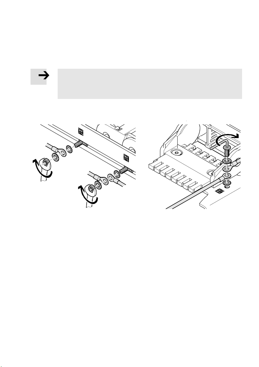
There are labelled earthing points on the handling system for earthing.
Note
Observe national regulations.
Pay attention to installation of the earthing cables in energy chains
(è 7.3 Cables and hoses).
Place cable lugs of the earthing cables between serrated washer and washer.
Tighten nut or bolt (tightening torque 4 Nm).
Festo – GDCP-YXC-EN – 1502NH – English 71
Page 72
7 Installation
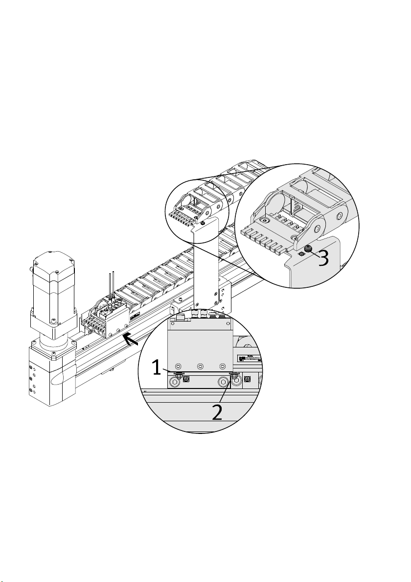
7.2.2 Earthing points at the single-axis system
Connect earthing point 1 (protective earth connection) with low impedance to the earth potential of
the system.
Connect earthing point 2 of the Y-module with low impedance to earthing point 3 at the moment
compensator.
Connect attachment components with low impedance to earthing point 3 at the moment com
pensator.
72 Festo – GDCP-YXC-EN – 1502NH – English
Page 73
7 Installation
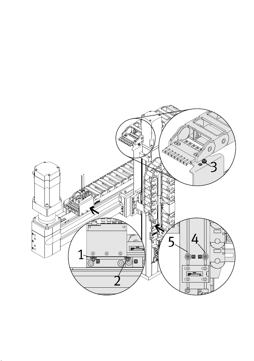
7.2.3 Earthing points at the linear gantry
Connect earthing point 1 (protective earth connection) with low impedance to the earth potential of
the system.
Connect earthing point 2 of the Y-module with low impedance to earthing point 3 at the moment
compensator.
Connect earthing point 3 at the moment compensator with low impedance to earthing point 4 of the
Z-module
Connect attachment components with low impedance to earthing point 5.
Festo – GDCP-YXC-EN – 1502NH – English 73
Page 74
7 Installation
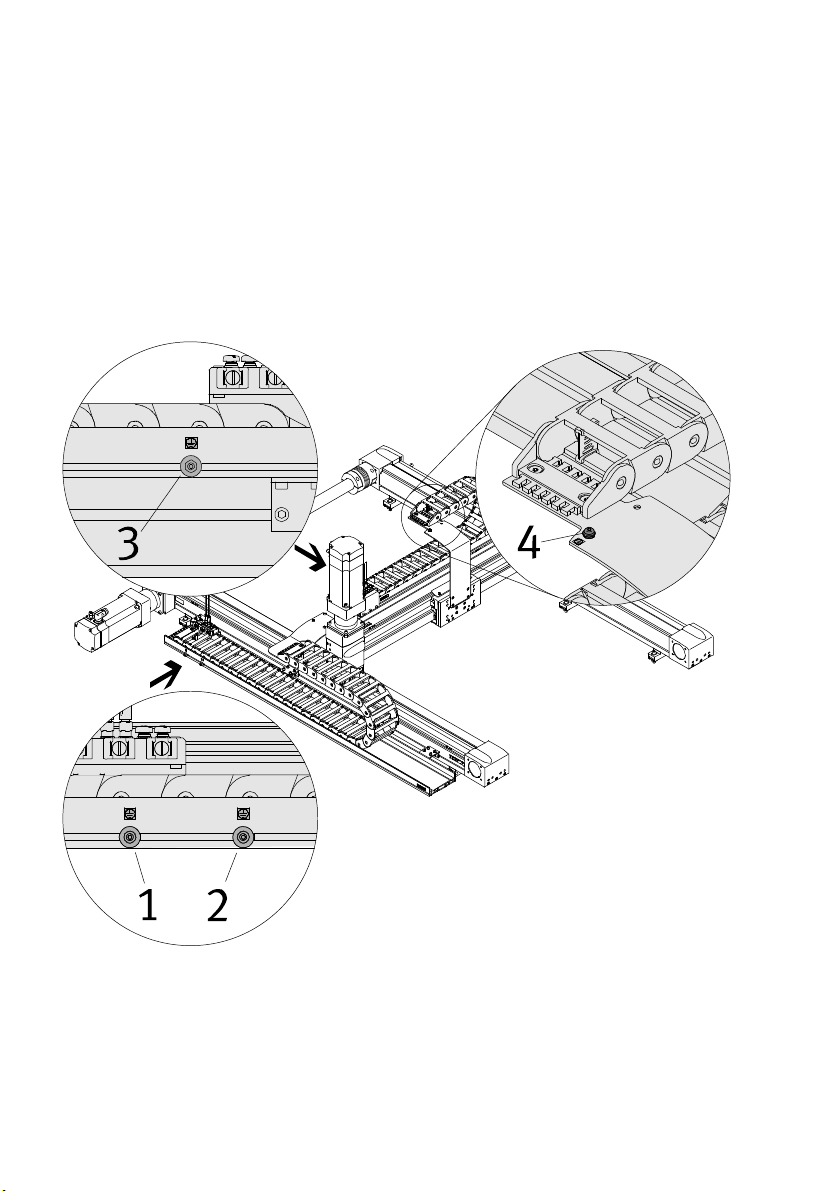
7.2.4 Earthing points at the planar surface gantry
Connect earthing point 1 (protective earth connection) with low impedance to the earth potential of
the system.
Connect earthing point 2 of the X-module with low impedance to earthing point 3 of the Y-module.
Connect earthing point 3 of the Y-module with low impedance to earthing point 4 at the moment
compensator.
Connect attachment components with low impedance to earthing point 4 at the moment com
pensator.
74 Festo – GDCP-YXC-EN – 1502NH – English
Page 75
7 Installation
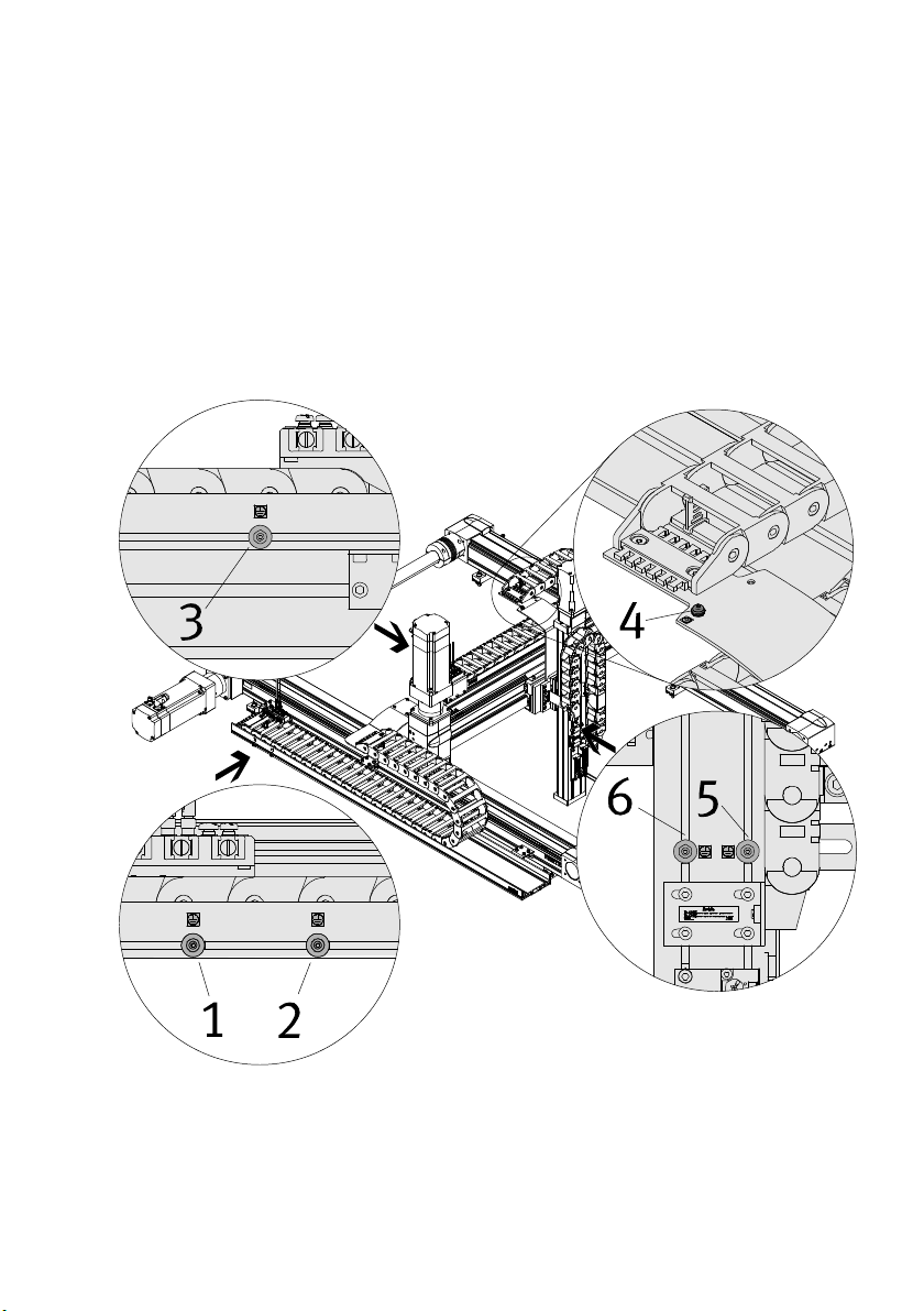
7.2.5 Earthing points at the three-dimensional gantry
Connect earthing point 1 (protective earth connection) with low impedance to the earth potential of
the system.
Connect earthing point 2 of the X-module with low impedance to earthing point 3 of the Y-module.
Connect earthing point 3 of the Y-module with low impedance to earthing point 4 at the moment
compensator.
Connect earthing point 4 at the moment compensator with low impedance to earthing point 5 of the
Z-module.
Connect attachment component with low impedance to earthing point 6.
Festo – GDCP-YXC-EN – 1502NH – English 75
Page 76
7 Installation
7.3 Cables and hoses
Cables and hoses are sized so that, at a minimum, the connection length specified when ordering is
available at the end of the energy chain.
Information
The cables are available only in fixed lengths.
The connection lengths at the end of the energy chain of the various cables may be differ
ent.
7.3.1 Completely mounted handling system
Cables and hoses are installed in the energy chains.
The energy chains are subdivided by separators into chambers. Each chamber is intended for a specific
application.
Install additionally required cables and hosed in accordance with the following instructions.
Later installation and connection to the control components may be carried out only by a
specialist with corresponding training.
7.3.2 Cables
Cables must be uniquely identifiable.
Label additional cables prior to installation.
Attach one inscription label each at the beginning and end of the cable, near the plug connector.
Inscription labels of the mounted cables are attached using the following system.
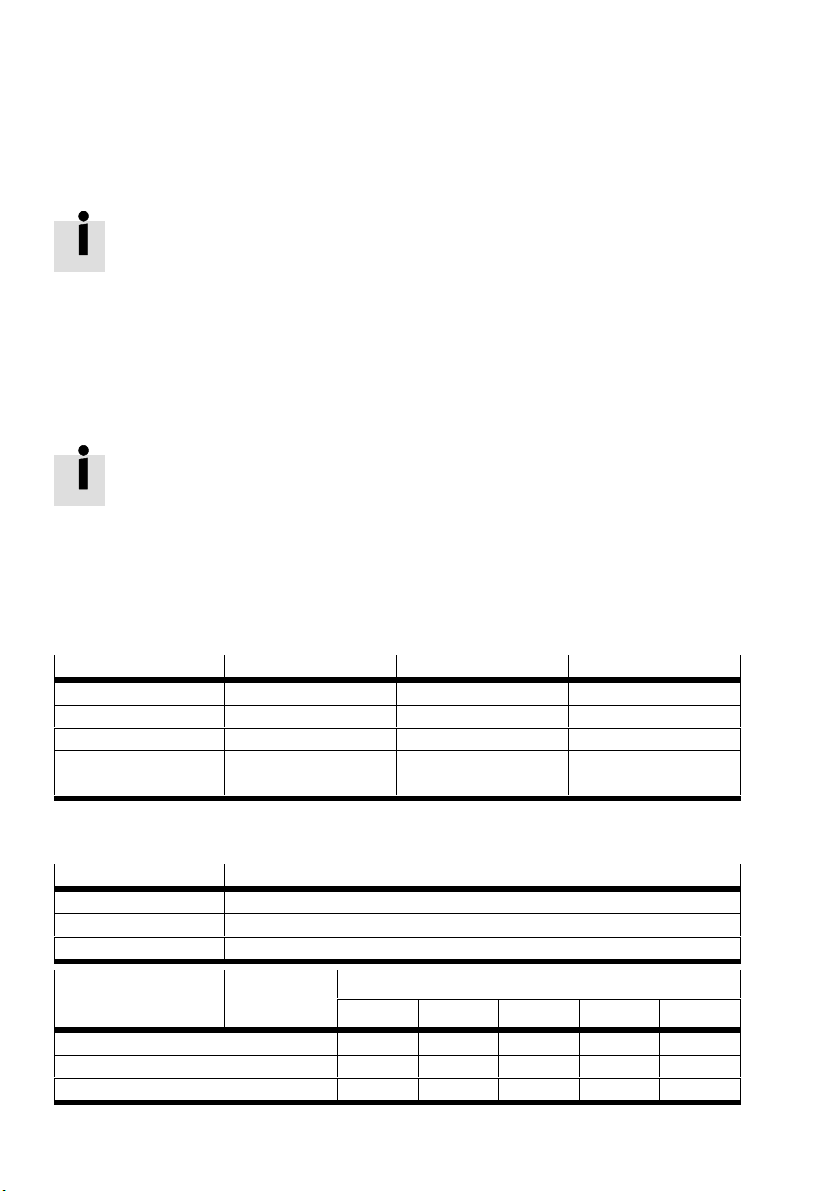
Cable EHMX EHMY EHMZ
Motor cable -1M1 -2M1 -3M1
Encoder cable -1B1 -2B1 -3B1
Multi-pin plug 1 -1X1 -2X1 -3X1
Multi-pin plug 2
(optional)
- - -3X2
7.3.3 Hoses
Hoses must be uniquely identifiable.
Hose colour Function
Black Extend pneumatic drive
Silver Retract pneumatic drive
Blue For customer-specific applications
Hose size Minimum
bending radi
us
PUN-3x0,5 12 mm x - - - PUN-4x0,75 17 mm - x x - PUN-6x1 26.5 mm - - - x x
76 Festo – GDCP-YXC-EN – 1502NH – English
DHMZ-DGSL-
6 12 16 20 25
Page 77
7 Installation
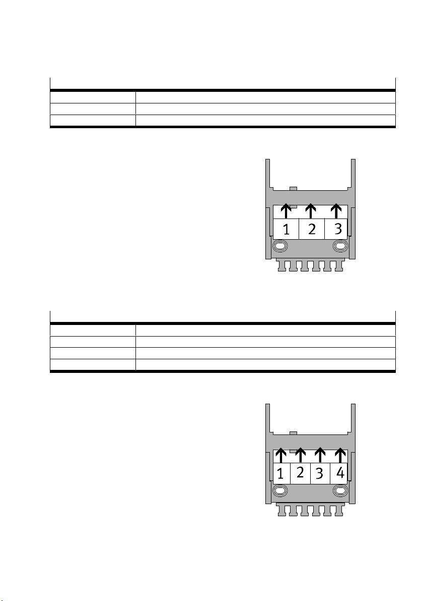
7.3.4 Energy chain subdivision Z-modules
Chambers for EHMZ-EGC
1)
1 For customer-specific allocation
2 Encoder cable and plug socket with cable
3 Motor cable (servo motor) and earthing cable
1) View of open end of the energy chain, Z-module to the left beside the energy chain
Chambers for EHMZ-DGEA or EHMZ-EGSL
1)
1 For customer-specific allocation
2 For customer-specific allocation
3 Plug sockets with cable
4 Earthing cable
1) View of open end of the energy chain, Z-module to the left beside the energy chain
Festo – GDCP-YXC-EN – 1502NH – English 77
Page 78
7 Installation
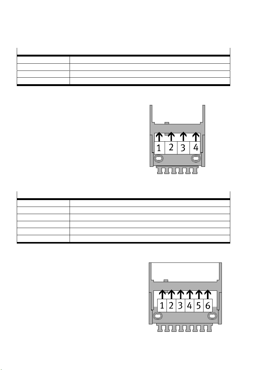
7.3.5 Energy chain subdivision Y-modules
Chambers for EHMY-LP-EGC-50
1)
1 Motor cable (stepper motor) or hoses for pneumatic drive
2 Plug sockets with cable and earthing cable
3 For customer-specific allocation
4 For customer-specific allocation
1) View of open end of the energy chain
Chambers for EHMY-RP-EGC-50, EHMY-LP/RP-EGC-80 or EHMY-RP-EGC-125-TB-HD
1)
1 Motor cable (servo motor)
2 Motor cable (servo motor) or hoses for pneumatic drive
3 Encoder cable and earthing cable
4 Plug sockets with cable
5 For customer-specific allocation
6 For customer-specific allocation
1) View of open end of the energy chain
78 Festo – GDCP-YXC-EN – 1502NH – English
Page 79
7 Installation
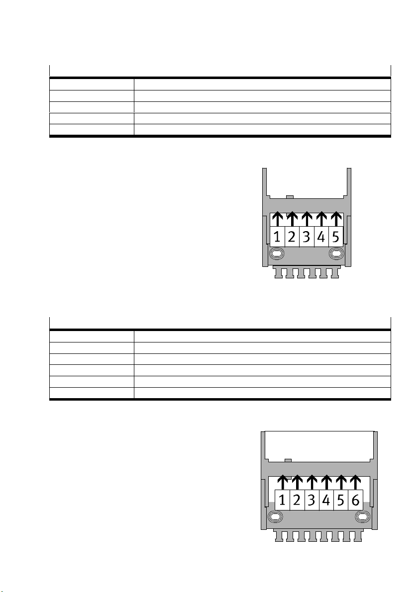
Chambers for EHMY-LP-EGC-125-TB-HD
1)
1 Motor cable (servo motor)
2 Encoder cables and earthing cable
3 Plug socket with cable
4 For customer-specific allocation or hoses
5 For customer-specific allocation
1) View of open end of the energy chain
Chambers for EHMY-LP/RP-EGC-120/-160/-185/-220
1)
1 Motor cable (servo motor) or hoses for pneumatic drive
2 Encoder cable and earthing cable
3 Plug sockets with cable
4 For customer-specific allocation
5 For customer-specific allocation
6 For customer-specific allocation
1) View of open end of the energy chain
Festo – GDCP-YXC-EN – 1502NH – English 79
Page 80
7 Installation
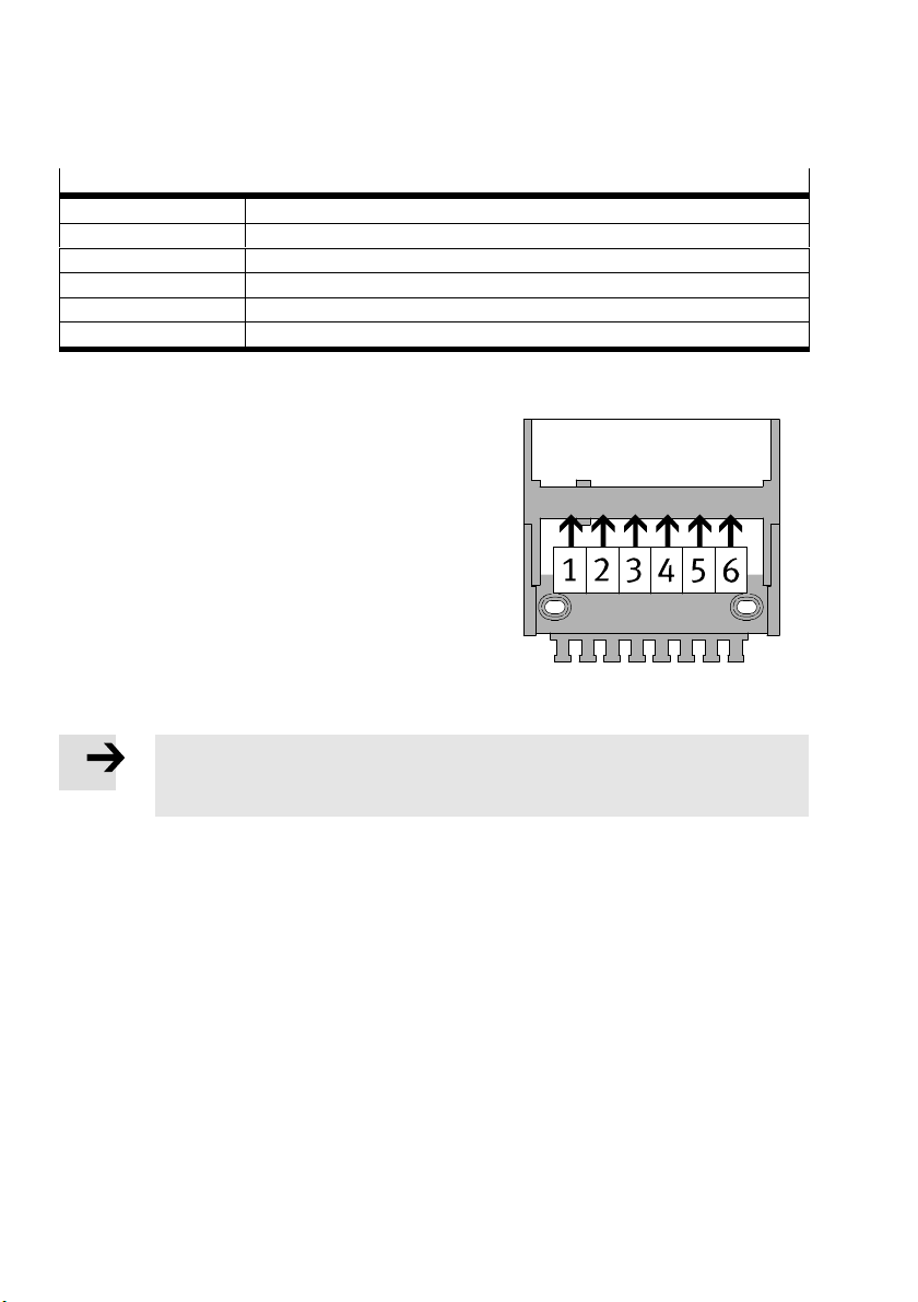
7.3.6 Energy chain subdivision X-modules
Chambers for EHMX-EGC-50/-80/-120/-185
1)
1 For customer-specific allocation
2 For customer-specific allocation
3 Plug socket with cable
4 Encoder cables and earthing cable
5 Motor cable (servo motor) or hoses for pneumatic drive
6 Motor cable (servo motor)
1) View of open end of the energy chain
7.3.7 Installation
Note
Hoses that are permanently in contact with cables can react negatively to their material.
Install hoses separately from the cables.
Install cables and hoses separately from each other. If required, add additional separators.
Do not put motor cables together with encoder cables or plug sockets with cables in one chamber.
Install cables and hoses twist-free and without mechanical tension. Cables and hoses must be able
to move freely within the curvature radius of the energy chain.
Attach cables and hoses to the chambers of the energy chain end pieces with cable ties.
Energy chain Z-module
1. Place customer-specific cables and hoses of the mounting parts into the corresponding chambers
of the energy chain Z.
Energy chain Y-module
1. Push the slide of the Y-module up to the end stop so that the maximum possible length of the en
ergy chain Y lies flat.
2. Place customer-specific cables and hoses from the energy chain Z into the energy chain Y.
80 Festo – GDCP-YXC-EN – 1502NH – English
Page 81
7 Installation
Energy chain X-module
1. Push the slide of the X-module up to the end stop so that the maximum possible length of the en
ergy chain lies flat.
2. Place customer-specific cables and hoses from the energy chain Y into the energy chain X.
Between the energy chains
Tie together cables using cable binders.
Tie hoses separately from the cables.
Observe minimum bending radius of the cables and hoses.
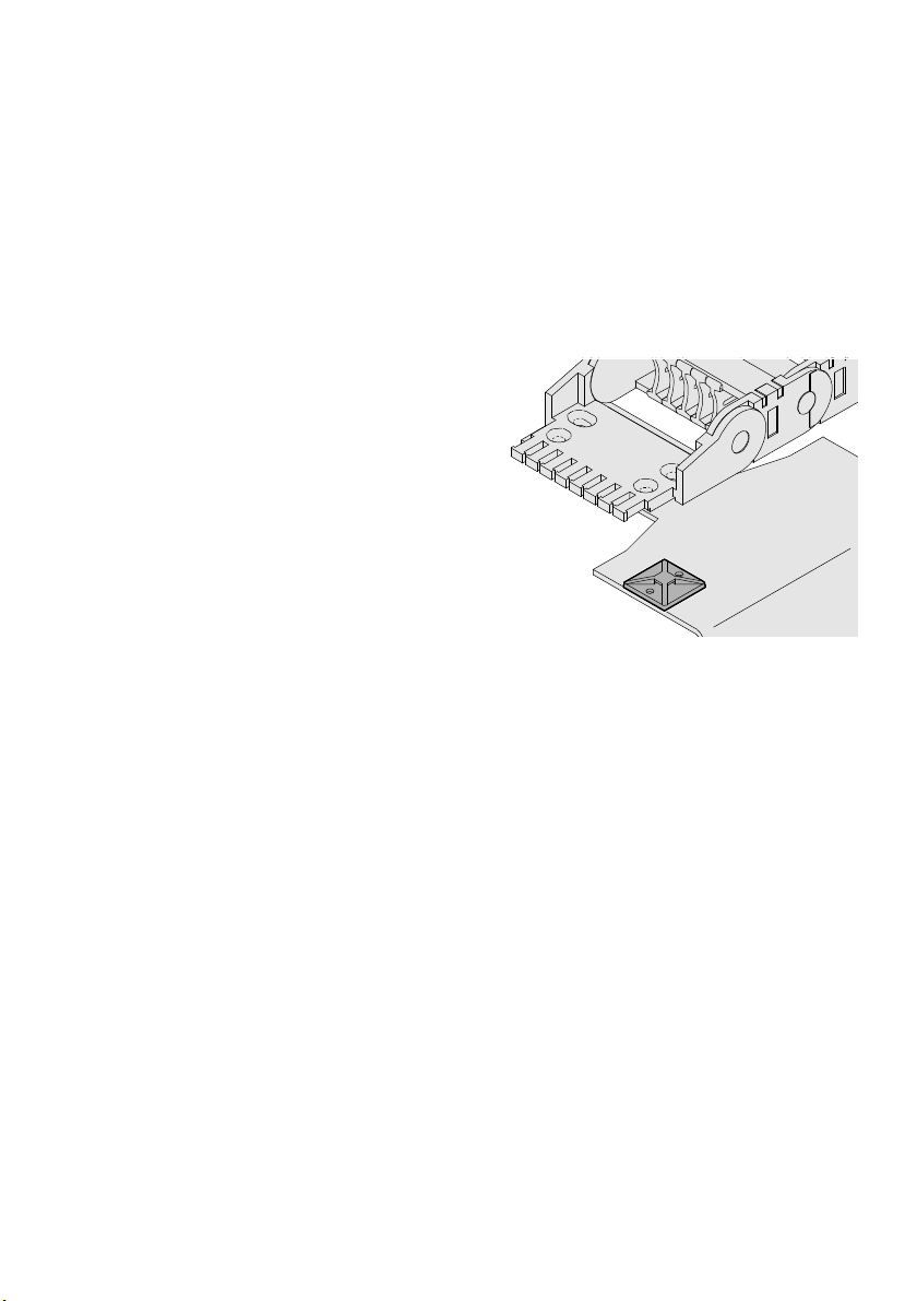
Attach the cable bundle or hose bundle to the
cable base with cable ties.
7.3.8 Checking the energy chain
Perform movement of the energy chains over the respective entire stroke.
– The energy chain must be able to move without hindrance.
Festo – GDCP-YXC-EN – 1502NH – English 81
Page 82
8 Commissioning
8 Commissioning
The following applies for commissioning of a system into which this handling system is integrated.
8.1 Safety instructions
Note
Guides of the handling system can be damaged.
The planar surface gantry or three-dimensional gantry may only be placed in operation
after it is aligned and checked
(è 5 Installation of the planar surface gantries and the three-dimensional gantries).
Note
The following conditions must be fulfilled for commissioning:
– The handling system is completely mounted.
– The handling system is aligned and checked.
– The electrical installation is complete and checked.
– The pneumatic installation is complete and checked.
Commissioning may only be performed by qualified specialized personnel who are famil
iar with:
– the Festo Configuration Tool (FCT)
– installation and operation of electrical control systems
– installation and operation of pneumatic systems
– installation and operation of handling systems
– the documentation for the product.
For support:
Contact your regional Festo contact person.
Further information è www.festo.com/sp.
Note
The power supply is not switched off.
Damage to the product from incorrect handling.
Never pull the plug connectors and electrical interfaces when powered.
Never connect the plug connectors and electrical interfaces when powered.
Observe the handling specifications for electrostatically sensitive devices.
Warning
The danger zone of the system is not sufficiently secured against access and contact
with moving parts.
Injury due to impact or pinching.
Before commissioning, take corresponding safeguarding measures, in order to fulfil
fundamental safety and health protection requirements.
82 Festo – GDCP-YXC-EN – 1502NH – English
Page 83
8 Commissioning
Danger
Switching on the energy supply as well as restoring it after an interruption or power
failure can result in uncontrolled movement.
Injury (death) due to impact or pinching. Damage to the product.
Before commissioning, take corresponding safeguarding measures, in order to fulfil
fundamental safety and health protection requirements.
Danger
Unpressurized pneumatic drives can move unthrottled and at high speed into the end
position when pneumatically actuated.
Injury (death) due to impact or pinching. Damage to the product.
Build pressure up slowly when switching on the compressed air supply.
Run pneumatic drives with reduced pressure into the end positions.
Caution
Narrow gaps between movable parts. Hair or loose clothing can get into the gaps and be
drawn in.
Injury from tearing, being pulled in, constriction.
Take corresponding safeguarding measures, e.g. hair nets, tight clothing.
Caution
Marked surfaces get very hot.
Injury from burns.
Before commissioning, take corresponding safeguarding measures, in order to fulfil
fundamental safety and health protection requirements.
Warning
Exposed, rotating connecting shaft.
Injury from being drawn in and burns.
Install safe protection devices, e.g. protective guards, covers.
Festo – GDCP-YXC-EN – 1502NH – English 83
Page 84

8 Commissioning
8.2 Proximity sensors
Proximity sensors are mounted as limit switches.
If the proximity sensors need to be moved, the following must be observed:
Mark position of the proximity sensors before moving, so the normal position can be reset if required.
Adjust the slot covers correspondingly.
Check handling system for collisions.
Check correct position of proximity sensors in a test run.
Observe the tightening torques (è Accompanying operating instructions for the proximity sensors).
8.3 Test run
Before final commissioning, the commissioner must perform a test run.
Remove remaining safety components of the moving components
(è 2.4.3 Securing during transport and mounting).
Start test run at crawling speed.
Check function of the limit switches.
Increase speed step by step up to the maximum necessary travel speed.
Eliminate malfunctions that occur (è 12 Fault clearance).
End the test run.
84 Festo – GDCP-YXC-EN – 1502NH – English
Page 85
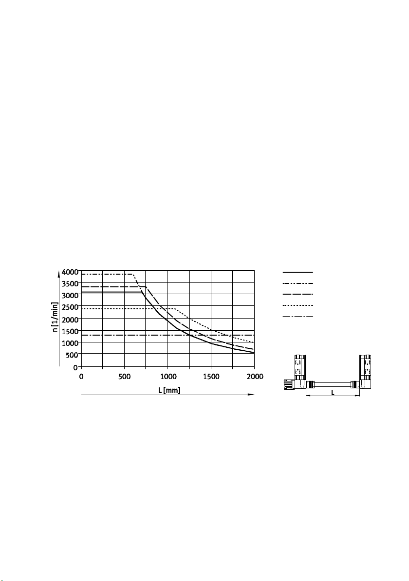
9 Operation
9 Operation
The following applies for operation of a system into which this handling system is integrated.
9.1 Safety instructions
Observe additional safety instructions in the following chapters:
– è 1 Safety and requirements for product use
– è 2 Conveying and storage
– è 8 Commissioning
9.2 Characteristic curve of the connecting shaft
The permitted limit speed depends on the order (è 1.1 Technical data).
If the conditions in real operation change:
Take into account the limit speed of the connecting shaft (KSK).
Maximum permitted speed n dependent on the length L1.
KSK-50
KSK-70
KSK-80
KSK-120
KSK-185
Festo – GDCP-YXC-EN – 1502NH – English 85
Page 86
10 Maintenance and care
10 Maintenance and care
10.1 Safety instructions
Note
Maintenance and care may only be performed by qualified specialized personnel who
are familiar with:
– installation and operation of electrical control systems
– installation and operation of pneumatic systems
– installation and operation of handling systems
– the documentation for the product.
For support:
Contact your regional Festo contact person.
Additional information è www.festo.com.
Note
The power supply is not switched off.
Damage to the product from incorrect handling.
Never pull the plug connectors and electrical interfaces when powered.
Never connect the plug connectors and electrical interfaces when powered.
Observe the handling specifications for electrostatically sensitive devices.
Danger
Injury (death) due to electric shock.
Switch off all supply lines prior to mounting, installation and/or maintenance work
and secure them from being switched back on.
After the supply voltage is switched off:
Start work on plug connectors and interfaces only when the residual voltage has
fallen to a harmless level (è Documentation of the controller used).
Switch the power supply back on only after completion of work.
Warning
Moving parts are not secured. Components are installed vertically or diagonally. Moving
parts run uncontrollably into the lower end position from their own dead weight.
Injury due to impact or pinching. Damage to the product.
Before mounting and before the power supply is switched off:
Bring vertically or diagonally moving parts into the lower end position in a controlled
manner.
Secure vertically or diagonally moving parts.
86 Festo – GDCP-YXC-EN – 1502NH – English
Page 87
10 Maintenance and care
Warning
Compressed air tubing or attachments are set free under pressure. Movable parts move
uncontrollably.
Injury (death) due to impact or pinching.
Switch off the compressed air supply prior to mounting work.
Support movable pneumatic components, if needed.
Vent all pneumatic components completely, e.g. through appropriate components,
such as non-return valves, service unit.
10.2 Cleaning
Use non-abrasive cleaning agents.
Clean the handling system as required with a soft cloth.
10.3 Lubrication
The handling system is lubricated initially.
Note
Trouble-free operation and a long service life require regular relubrication.
Lubricate axes properly.
Observe specifications for lubrication.
Use appropriate grease gun. Accessories (è www.festo.com/catalogue).
Requirements
Lubrication interval [km] 2500
Lubricating grease See documentation for the axes (è www.festo.com/sp)
Amount of lubricant See documentation for the axes (è www.festo.com/sp)
Festo – GDCP-YXC-EN – 1502NH – English 87
Page 88
11 De-commissioning, dismantling, disposal
11 De-commissioning, dismantling, disposal
11.1 Safety instructions
11.1.1 General
Observe additional safety instructions in the following chapters:
– è 1 Safety and requirements for product use
– è 2 Conveying and storage
– è 8 Commissioning
– è 10 Maintenance and care
11.1.2 Dismantling
Warning
Modules are dismantled without securing movable parts. Movable parts move uncon
trollably.
Injury due to impact or pinching.
Secure movable parts prior to dismantling using cable ties and supplied components
(è 2.4.3 Securing during transport and mounting).
11.1.3 Disposal
Incorrect disposal is harmful to the environment.
Observe the local regulations for disposal of modules.
Process lubricants (greases/oils) in accordance with the applicable regulations for
health and safety and hazardous substances.
Observe the local regulations regarding waste disposal and the environment.
88 Festo – GDCP-YXC-EN – 1502NH – English
Page 89
12 Fault clearance
12 Fault clearance
12.1 Malfunctions and remedy
Malfunction Cause Remedy
Jerking travel
Y-module tilted
Y-module does not move
Motor does not rotate Controller has not yet been
Motor turns in the wrong
direction or vibrates
Y-module travels over end
position
Connecting shaft makes
scraping noise
Coupling broken at connecting
shaft
Overloading Reduce mass of the moving
load/travel speed.
Comply with limit value.
Connecting tube slips through Correct mounting of the
connecting shaft:
Clean contact surfaces.
Comply with dimension B.
Tighten screws.
Tension Check permitted flatness of
the mounting surface.
Align axes/slides.
Lubricate axes.
Change travel speed.
Incorrect controller settings Change controller
parameters.
Check controller signal.
enabled
Holding brake active (for motor
with brake)
Cabling error Check and correct cabling.
Incorrect controller settings Change controller
Proximity sensors do not
operate
Too much offset Align axes/slides.
Overloading Replace coupling.
Too much offset
Tension
Release brake.
parameters.
Check proximity switch,
connections and controller.
Observe limit values.
Align axes/slides.
If the remedy does not result in fault clearance (è 12.2 Repair).
Festo – GDCP-YXC-EN – 1502NH – English 89
Page 90

12 Fault clearance
12.2 Repair
Contact Festo Service.
This way the required fine tuning and tests will be taken into special consideration.
Information about spare parts and accessories (è www.festo.com/spareparts).
90 Festo – GDCP-YXC-EN – 1502NH – English
Page 91
A Technical appendix
A Technical appendix
A.1 Technical data
Note
The technical data depend on the configuration and are contained in a separate data
sheet.
Damage to the product from incorrect use and non-compliance with the technical data.
The separate data sheet is a component of the product documentation.
Determine order ID of the handling system (è Product labelling on the Y-module).
Download data sheet from the Festo Support Portal by specifying the order ID
(è www.festo.com).
Print out data sheet and store it together with this description at the product.
A.1.1 Certifications
Declaration of incorporation (è www.festo.com) in accordance with Machinery Directive 2006/42/EC
A.1.2 Materials
Component
Profiles of the axes Aluminium
Drive cover
End cap
Adapter plates
Energy chain support profile
Slide
Coupling Aluminium with elastomer ring gear
Guide Steel
Screws and centring pins
Ball bearings
Toothed belt pulleys/flanged pulleys High-alloy steel
Multiple connector plate holder
Moment compensator
Energy chains Plastic
Buffer NBR
Cover caps POM
Toothed belt Polychloroprene with glass cord and nylon coating
Festo – GDCP-YXC-EN – 1502NH – English 91
Page 92

Reproduction, distribution or sale of this document or communica
tion of its contents to others without express authorization is
prohibited. Offenders will be liable for damages. All rights re
served in the event that a patent, utility model or design patent is
registered.
Copyright:
Festo AG & Co. KG
Postfach
73726 Esslingen
Germany
Phone:
+49 711 347-0
Fax:
+49 711 347-2144
e-mail:
[email protected]
Internet:
www.festo.com
Original: de
 Loading...