

Page 1
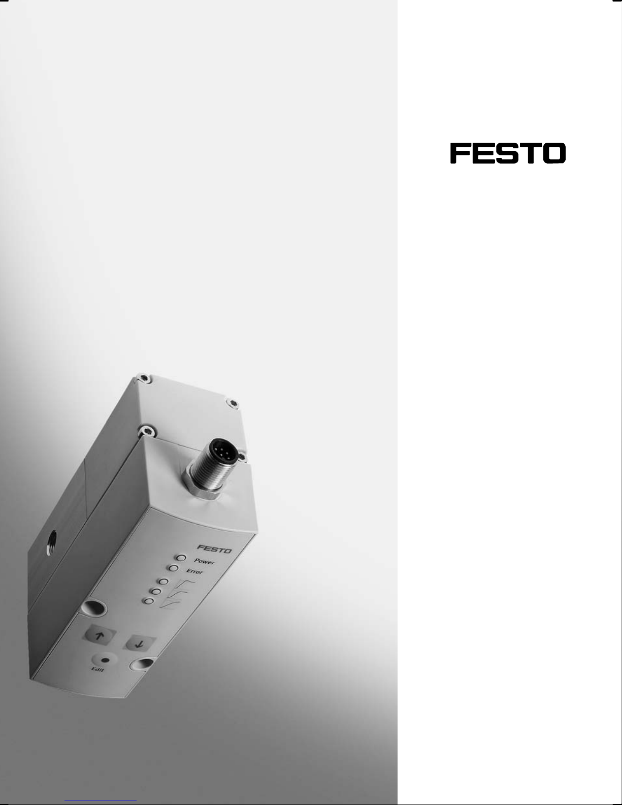
Proportional Druckregelventil
Proportional pressure regulator
VPPM−...
(de) Bedienungs−
anleitung
(en) Operating
instructions
nicht für
Typ VPPM−...C1
not for
type VPPM−...C1
741 073
0810b
Page 2
VPPM−...−DE/EN
Symbole/Symbols:
Warnung
Warning, Caution
Hinweis
Please note
Umwelt
Antipollution
Zubehör
Accessories
Einbau und Inbetriebnahme nur von qualifi
ziertem Fachpersonal, gemäß Bedienungs
anleitung.
Fitting and commissioning to be carried out
by qualified personnel only in accordance
with the operating instructions.
Deutsch 3 . . . . . . . . . . . . . . . . . . . . . . . . . . . .
English 23 . . . . . . . . . .
2
. . . . . . . . . . . . . . . . . . . . . . . . . . . . . . . . . . . . . . . . . . . . . . . . . . . . . . . . . .
. . . . . . . . . . . . . . . . . . . . . . . . . . . . . . . . . . . . . . .
Festo VPPM−... 0810b
Page 3

VPPM−...−DE/EN
Proportional Druckregelventil Typ VPPM−...Deutsch
Inhaltsverzeichnis
1 Anschlüsse, Bedienteile und Varianten 4 . . . . . . . . . . . . . . . . . . . . . . . . . . .
Bedienteile und Anschlüsse des VPPM−... (Muffenventil) 4 . . . . . . . . . . . . .
Pneumatische
Varianten des VPPM−... 6 . . . . . . . . . . . . . . . . . . . . . . . . . . . . .
Anschlüsse des VPPM−... (Flanschventil) 5 . . . . . . . . . . . . . .
. . . . . . . . . . . .
2 Funktion und Anwendung 7 . . . . . . . . . . . . . . . . . . . . . . . . . . . . . . . . . . . .
3 Voraussetzungen für den Produkteinsatz 7 . . . . . . . . . . . . . . . . . . . . . . . . .
4 Einbau 8 . . . . . . . . . . . . . . . . . .
Mechanisch 8 . . . . . . . . . . . . . .
Pneumatisch 11 . . . . . . . . . . . . .
Elektrisch 11 . . . . . . . . . . . . . .
5 Inbetriebnahme 14 . . . . . . . . . . .
6 Bedienung und Betrieb 16 . . . . . . . . . . . . .
7 Wartung und Pflege 16 . . . . . . . . . . . . . . . . . . . .
8 Ausbau 17 . . . . . . . . . . . . . . . . . . . . . . . . . . .
9 Zubehör 17 . . . . . . . . . . . . . . . . . . . . . .
10 Sicherheitseinstellung 18 . . . . . . . . . . . . . . . . . . .
11 Störungsbeseitigung 18 . . . . . . . . . . . . . . . . . . . . . . . . . . . .
. . . . . . . . . . . . . . . . . . . . . . . . . . . . . . . . . . . .
. . . . . . . . . . . . . . . . . . . . . . . . . . . . . . . . . . . .
. . . . . . . . . . . . . . . . . . . . . . . . . . . . . . . . . . . .
. . . . . . . . . . . . . . . . . . . . . . . . . . . . . . . . . . . . . .
. . . . . . . . . . . . . . . . . . . . . . . . . . . . . . . . . . .
. . . . . . . . . . . . . . . . . . . . . . . . . . .
. . . . . . . . . . . . . . . . . . . . . . .
. . . . . . . . . . . . . . . . . . . . . . . . . . .
. . . . . . . . . . . . . . . . . . . . . . . . . . . . . . .
. . . . . . . . . . . . . . . . . . . . .
. . . . . . . . . . . . . .
. .
12 Technische Daten 20 . . . . . . . . . . . . . . . . . . . . . . . . . . . . . . . . . . .
Festo VPPM−... 0810b Deutsch
. . . . . . . . . .
3
Page 4
VPPM−...−DE/EN
1 Anschlüsse, Bedienteile und Varianten
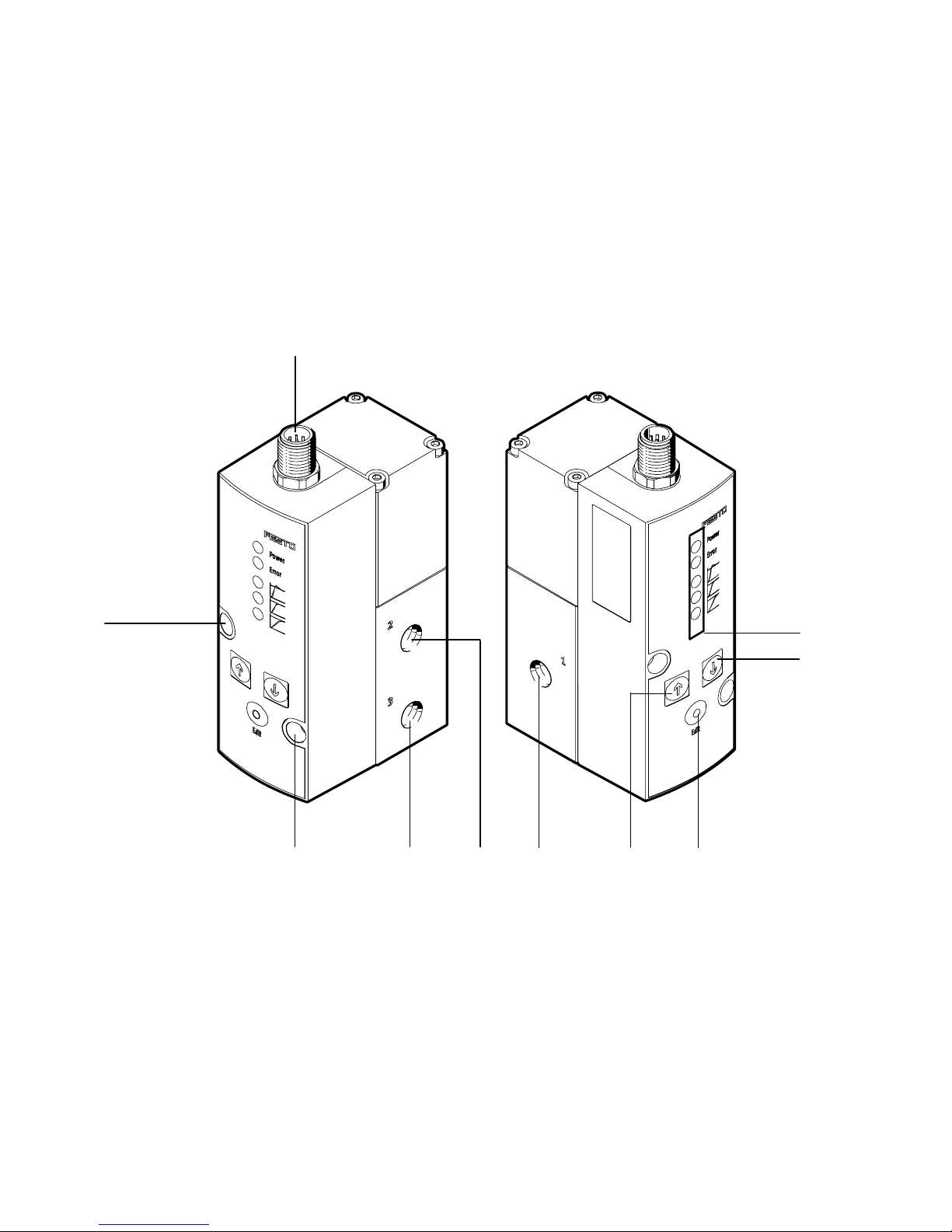
Bedienteile und Anschlüsse des VPPM−... (Muffenventil)
1
9
1
Stecker für elektrischen Anschluss (8−polig)
2 LED Betriebs− und Statusanzeigen
3 DOWN−Taste
4 EDIT−Taste
5 UP−Taste
8
56479
6 Druckluftanschluss 1 (Druckeingang)
7 Arbeitsluftanschluss 2 (Druckausgang)
8 Entlüftungsanschluss 3
9 Durchgangsbohrungen zur Befestigung
2
3
Bild1
4
Festo VPPM−... 0810b Deutsch
Page 5
VPPM−...−DE/EN
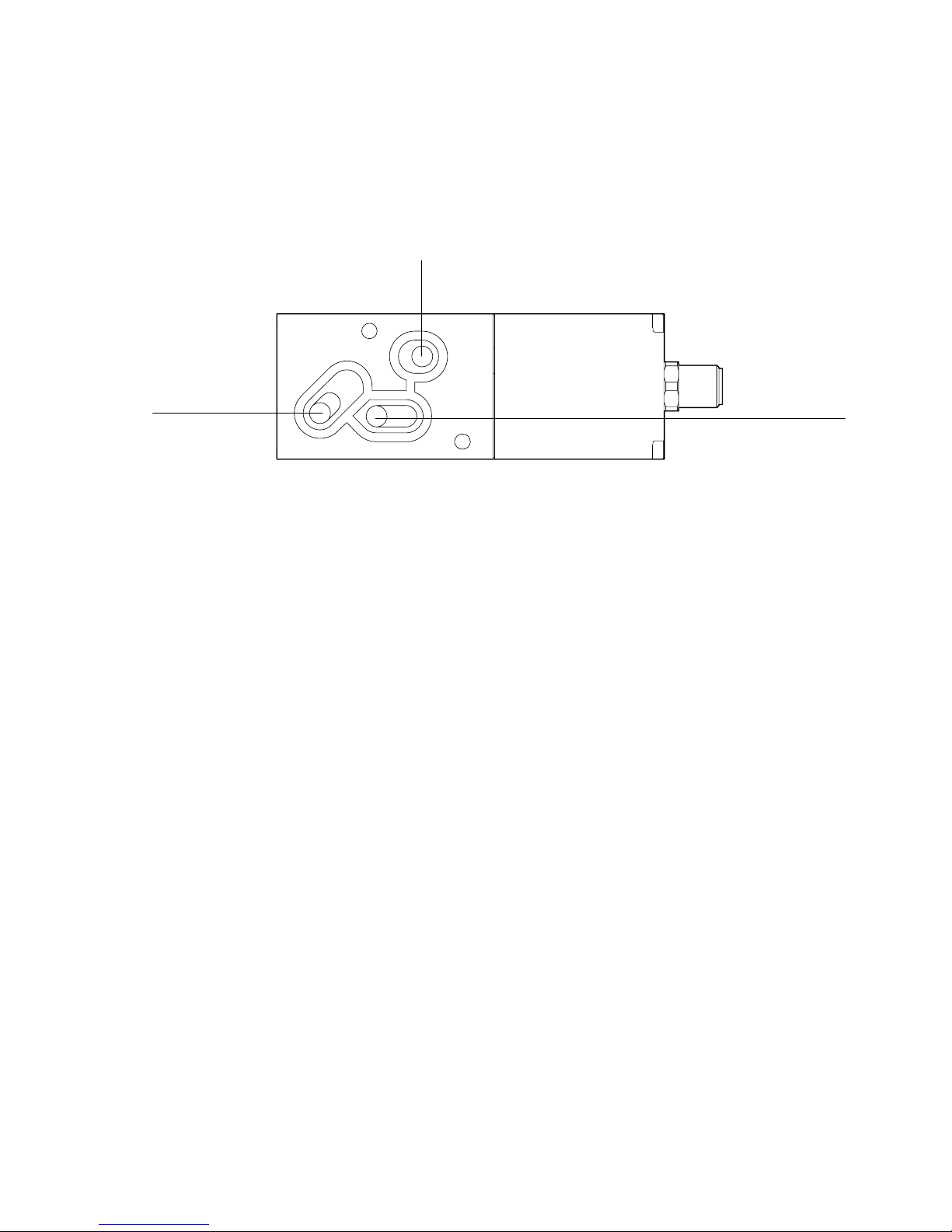
Pneumatische Anschlüsse des VPPM−... (Flanschventil)
2
3
1 Kanal Druckluft (Druckeingang)
2 Kanal Arbeitsluft (Druckausgang)
Bild2
1
3 Kanal Entlüftung
Festo VPPM−... 0810b Deutsch
5
Page 6
VPPM−...−DE/EN
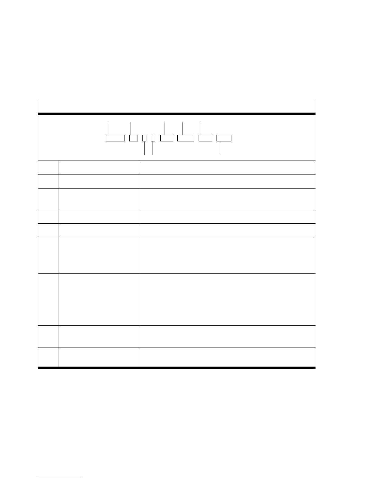
Varianten des VPPM−...
Typenschlüssel des VPPM−...
1
2
5
6
7
VPPM − 6L − L − 1 − G18 − 0L6H − V1N − S1
3
Pos. Merkmale Bezeichnung
1 Druckregelventil VPPM
2 Nennweite in [mm]
Ventilart
3 Dynamikklasse L (Low) / M (Medium) / H (High)
4 Ventilfunktion 1 (3−Wege−Druckregelventil, Ruhestellung geschlossen)
5 Pneumatischer Anschluss
Flansch/Anschlussplatte
ISO−Gewinde
NPT−Gewinde
6 Standart−Regelbereiche:
unterer Druckwert
oberer Druckwert
Alternative Regelbereiche:
unterer Druckwert
oberer Druckwert
4
6
F (Flansch) / L (Muffe)
F
G12 (1/2") / G14 (1/4") / G18 (1/8")
N12 (NPT 1/2) / N14 (NPT 1/4) / N18 (NPT 1/8)
0L (0 bar)
2H (2 bar) / 6H (6 bar) / 10H (10 bar)
...L (... = Wert zwischen 0 ... 10 bar, z.B. 4L)
...H (... = Wert zwischen 0 ... 10 bar, z.B. 8H)
8
7 Sollwertvorgabe
Schaltausgang
8 Gesamtgenauigkeit
Bediengerät
Bild3
6
A4 (4 ... 20 mA) / V1 (0 ... 10 V)
P (PNP) / N (NPN; Standard)
... (2 %) / S1 (1 %)
... (LED) / C1 (LCD)
Festo VPPM−... 0810b Deutsch
Page 7
VPPM−...−DE/EN
2 Funktion und Anwendung
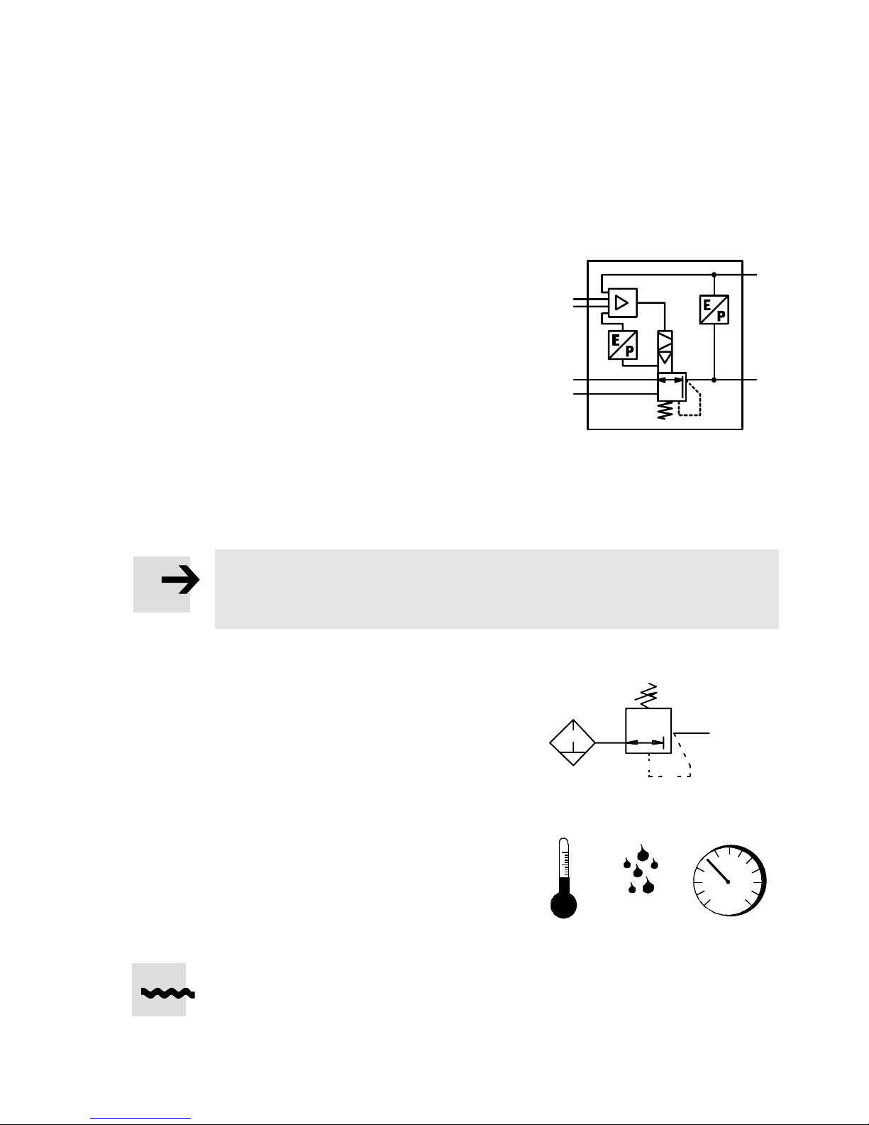
Das VPPM−... dient bestimmungsgemäß zum
Regeln eines Druckes proportional zu einem
vorgegebenen Sollwert. Ein integrierter Druck
+W
−W
sensor nimmt dazu den Druck am Arbeitsan
schluss auf und vergleicht diesen Wert mit
dem Sollwert. Bei Soll−Ist−Abweichungen wird
das Regelventil solange betätigt, bis der Aus
gangsdruck den Sollwert erreicht hat.
Bild4
3 Voraussetzungen für den Produkteinsatz
Hinweis
Durch unsachgemäße Handhabung entstehen Fehlfunktionen.
S Stellen Sie sicher, dass die folgenden Vorgaben stets eingehalten werden.
S Vergleichen Sie die Grenzwerte in dieser
Bedienungsanleitung mit denen Ihres Ein
satzfalls (z.B. Betriebsmedium, Drücke,
Kräfte, Momente, Temperaturen, Massen,
Geschwindigkeiten, Spannungen).
LF−... LR−...
X
3
1
2
S Berücksichtigen Sie die Umgebungs
bedingungen am Einsatzort.
S Berücksichtigen Sie die Vorschriften der
Berufsgenossenschaft, des Technischen
Überwachungsvereins, des VDE
entsprechende nationale Bestimmungen.
S Entfernen Sie die Transportvorkehrungen
wie Schutzwachs, Folien (Polyamid),
Kappen (Polyethylen), Kartonagen.
Die Verpackungen sind vorgesehen für
eine Verwertung auf stofflicher Basis (Aus
nahme: Ölpapier = Restmüll).
Festo VPPM−... 0810b Deutsch
Bild5
[°C] [%] [mbar]
oder
Bild6
7
Page 8
VPPM−...−DE/EN
S Verwenden Sie den Artikel im Originalzustand ohne jegliche eigenmächtige
Veränderung.
S Berücksichtigen Sie die Warnungen und Hinweise am Produkt und in dieser
Bedienungsanleitung.
S Sorgen Sie für ordnungsgemäß aufbereitete Druckluft
(siehe Abschnitt 9 Technische Daten").
S Belüften Sie Ihre gesamte Anlage langsam. Dann treten keine unkontrollierten
Bewegungen auf.
4 Einbau
Mechanisch
Hinweis
S Der Einbau und die Inbetriebnahme darf nur gemäß der Bedienungsanleitung
und von qualifiziertem Fachpersonal erfolgen.
S Behandeln Sie das VPPM−... so, dass keine Schäden am elektrischen
Anschluss auftreten. Diese können zur Minderung der Funktionssicherheit
führen.
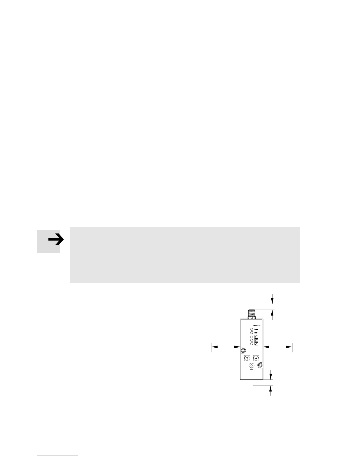
S Achten Sie auf genügend Platz für den
Kabelanschluss und die Schlauchan
schlüsse. Dadurch wird ein Abknicken des
Anschlusskabels vermieden.
S Platzieren Sie das VPPM−... möglichst nahe
am Verbraucher. Dies führt zu besserer
Regelgenauigkeit und kürzeren Ansprech
zeiten.
8
Bild7
Festo VPPM−... 0810b Deutsch
Page 9
VPPM−...−DE/EN
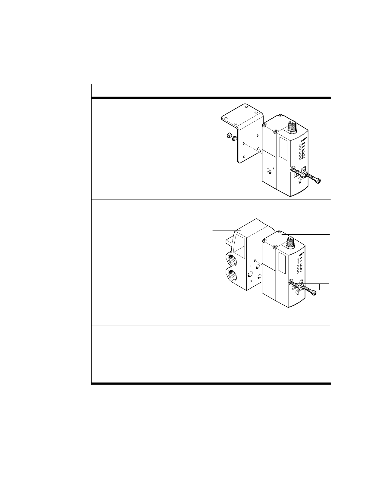
Befestigung an einer Wand bzw. Fläche
S Befestigen Sie das VPPM−... an der
Lage der Befestigungsbohrungen
Anziehdrehmoment: 1,0 Nm.
vorgesehenen Stelle mit zwei
M4−Schrauben. Verwenden Sie ggf.
hierzu den Winkel Typ VAME−P1−A (siehe
Bild). Bei Montage des VPPM mit Hilfe
des Winkels darf das VPPM−... nur
statisch Belastet werden.
sieheBild.
Befestigung auf dem Anschlussblock
S Befestigen Sie das VPPM−... 2 auf dem
Anschlussplock 1
Typ VABM−P1−SF−G18−...
Lage der Befestigungsbohrungen siehe
Position 3 im Bild rechts
Anziehdrehmoment: 1,5 Nm
1
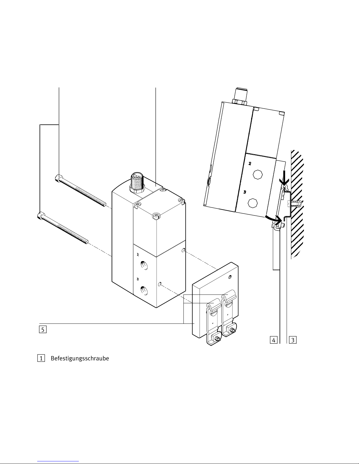
Befestigung auf der Hutschiene (siehe Bild9)
S Montieren Sie den Hutschienenadapter Typ VAME−P1−T mit Hilfe der beigelegten
Schrauben an das VPPM−... (Anzugsdrehmoment ca. 1,0 Nm):
für x": M4 x 65
für ¼": M4 x 75
S Hängen Sie das VPPM−... in die Hutschiene.
S Sichern Sie das VPPM−... mit den Sicherungsschrauben des Hutschienenadapters
(Anziehdrehmoment 1,5 Nm).
2
3
Bild8
Festo VPPM−... 0810b Deutsch
9
Page 10
VPPM−...−DE/EN
1
2
1 Befestigungsschrauben M4
(Anziehdrehmoment siehe Bild8)
2 VPPM−...
3 Hutschiene
Bild9
10
453
4 Hutschienen−Klemmeinheit
5 Hutschienenadapter Typ VAME−P1−T
Festo VPPM−... 0810b Deutsch
Page 11
VPPM−...−DE/EN
Pneumatisch
S Entfernen Sie die Verschlusselemente an den Druckluftanschlüssen.
S Verschlauchen Sie den Druckluftanschluss 6 und den Arbeitsluftanschluss 7
Elektrisch
Warnung
S Verwenden Sie ausschließlich Stromquellen, die eine sichere elektrische
(siehe Bild1). Drehen Sie einen Schalldämpfer in den Entlüftungsanschluss 8
Trennung der Betriebsspannung nach IEC/DIN EN 60204−1 gewährleisten.
Berücksichtigen Sie zusätzlich die allgemeinen Anforderungen an PELV−
Stromkreise gemäß IEC/DIN EN 60204−1.
.
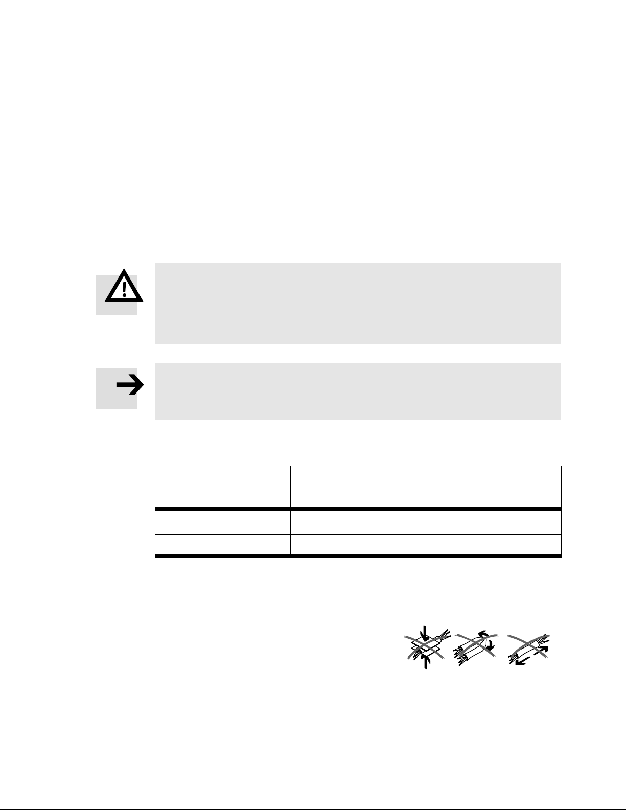
Hinweis
Lange Signalleitungen reduzieren die Störfestigkeit.
S Stellen Sie sicher, dass die Signalleitungen stets kürzer sind als 10 m.
S Überprüfen Sie anhand des Typenschildes welche Ventilvariante Ihnen vorliegt:
Bezeichnung auf dem Typenschild
VPPM−...−V1... VPPM−...−A4...
Benennung Spannungsvariante
Elektrischer Sollwert DC 0 ... 10 V 4 ... 20 mA
Bild10
Stromvariante
S Prüfen Sie die Verwendung folgender Optionen am VPPM−...:
Messung des Spannungs− bzw. Strom−Istwerts.
S Stellen Sie sicher, dass die Kabel
quetsch−, knick− und dehnungsfrei verlegt
sind:
S Verwenden Sie das vorkonfektionierte
Steckdosenkabel von Festo (siehe
Abschnitt 9 Zubehör"). Dadurch ist
gewährleistet, dass die vorgegebene
Schutzart IP65 und EMV erreicht wird.
Festo VPPM−... 0810b Deutsch
Bild11
11
Page 12
VPPM−...−DE/EN
S Wenn ein abgeschirmtes Kabel verwendet wird, erden Sie die Abschirmung am
Hinweis
Beim Anschluss des Y−Anschlusskabels Typ NEBV−M12G8−KD−..−M12G5 an CPX−E/A−
Module ist die galvanische Trennung der E/A−Module nicht mehr gewährleistet!
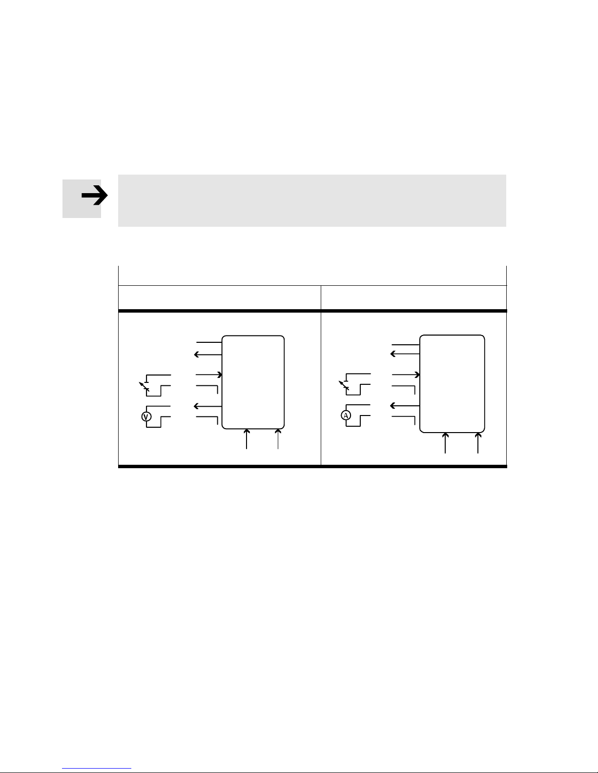
S Verkabeln Sie das VPPM−... gemäß eines der entsprechenden Anschlussbilder:
Anschlussbilder VPPM−...
Spannungsvariante (Typ VPPM−...−V1...) Stromvariante (Typ VPPM−...−A4...)
VPPM−fernen Kabelende.
0...10 V
Bild12
D3
U
v
out
W+
W−
X
GND
PIN
2
8
4
3
6
7
1
D1 ext in D2 ext in
PIN
2
U
v
D3
out
4...20 mA
W+
W−
GND
5
8
4
3
6
X
7
1
5
D1 ext in D2 ext in
12
Festo VPPM−... 0810b Deutsch
Page 13
VPPM−...−DE/EN
)
8
1
2
8
1
2
3
5
64
5
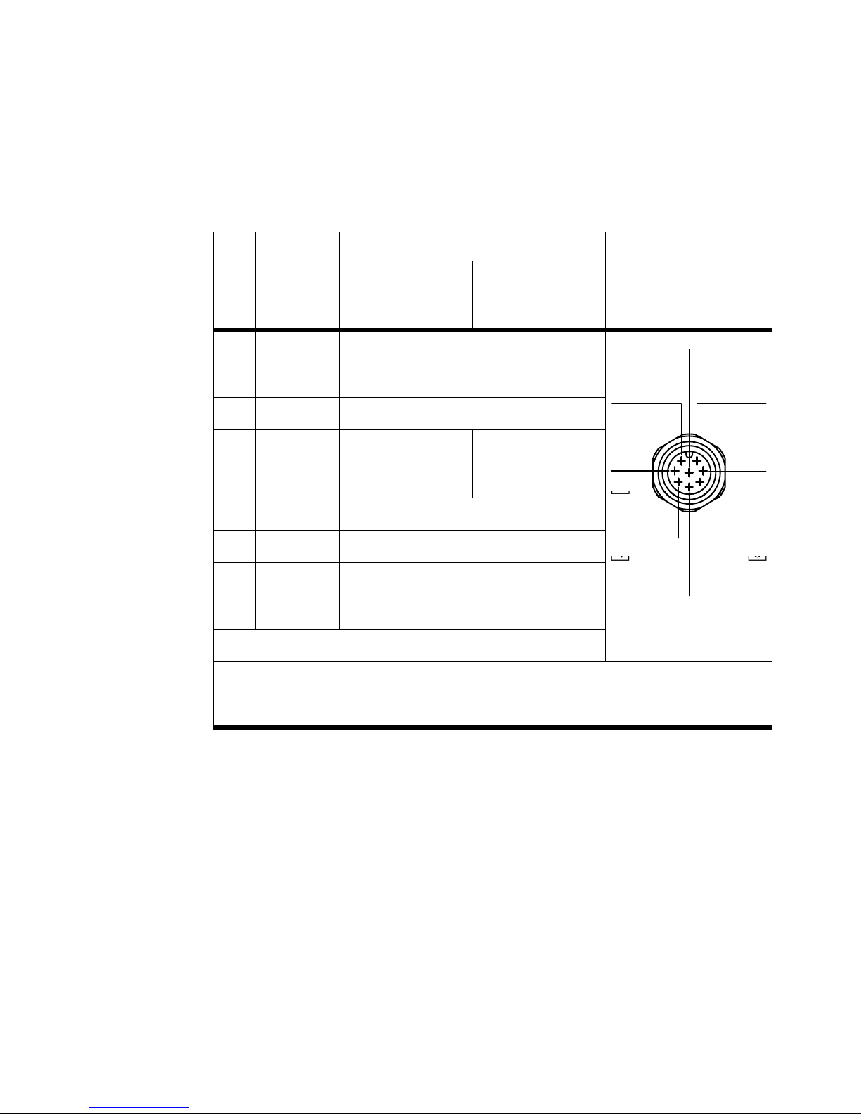
S Die einzelnen Pins am elektrischen Anschluss sind folgendermaßen belegt:
Pin
1 weiß (WH) Digitaler Eingang D1
2 braun (BN) DC +24 V Versorgungsspannung
3 grün (GN) Analoger Eingang W− (− Sollwert)
4 gelb (YE) Analoger Eingang
5 grau (GY) Digitaler Eingang D2
6 rosa (PK) Analoger Ausgang X (Istwert)
7 blau (BU) DC 0 V oder GND
8 rot (RD)
PE Schirmgeflecht auf Gewinde
Kabel−
farben
Anschlussbezeichnungen Stecker M12
1
Spannungs
variante Typ
VPPM−...−V1...
W+ (+ Sollwert)
0 ... 10 V
Digitaler Ausgang D3
Stromvariante
Typ
VPPM−...−A4...
Analoger Eingang
W+ (+ Sollwert)
4 ... 20 mA
3)
2)
7
3
64
1) Bei Verwendung der Anschlussdose mit Kabel lt. Zubehör
2) Das Anziehdrehmoment beträgt max. 0,5 Nm
3) Die Hysterese des digitalen Komparatorausgangs D3 beträgt 0,5% FS
Bild13
Festo VPPM−... 0810b Deutsch
13
Page 14
VPPM−...−DE/EN
3
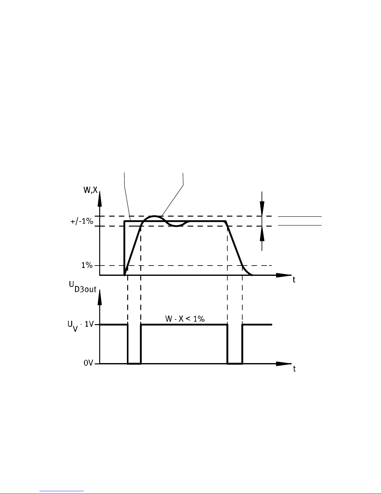
Digitaler Komparatorausgang D3
Die Funktion Druck erreicht" ermöglicht die Überwachung der Druckregelfunk
tion. Dazu wird der Sollwert mit dem Istwert verglichen.
Der digitale Schaltausgang D3 wird aktiv, sobald die Regelabweichung ˚ 0,5% FS
beträgt und wird inaktiv, wenn die Regelabweichung > 1% FS überschreitet.
Diagramm zur Schaltvariante PNP
12
1 Sollwert
2 Istwert
4
3 obere Toleranzgrenze
4 untere Toleranzgrenze
Bild14: P−Variante (PNP)
14
Festo VPPM−... 0810b Deutsch
Page 15
VPPM−...−DE/EN
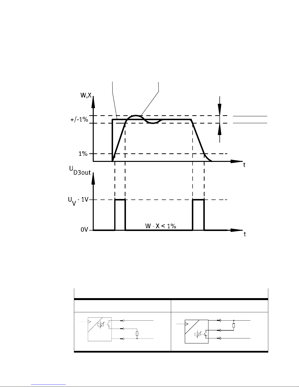
Diagramm zur Schaltvariante NPN
12
3
4
1 Sollwert
2 Istwert
Bild15: N−Variante (NPN)
Schaltbilder VPPM−... Schaltausgang
PNP NPN
P
PNP
Bild16
Festo VPPM−... 0810b Deutsch
3 obere Toleranzgrenze
4 untere Toleranzgrenze
2
2
BN
RD
8
BU
7
R
+24 V
L
0 V
P
NPN
BN
R
RD
8
7
BU
+24 V
L
0 V
15
Page 16
VPPM−...−DE/EN
5 Inbetriebnahme
Hinweis
S Stellen Sie sicher, dass hochfrequente Einstrahlungen (z.B. durch Funkgeräte,
Funktelefone oder sonstige störaussendende Geräte) vom VPPM−... fern
gehalten werden. So vermeiden Sie erhöhte Toleranzen des Ausgangsdrucks
(vgl. Angaben zur EMV im Abschnitt 12 Technische Daten").
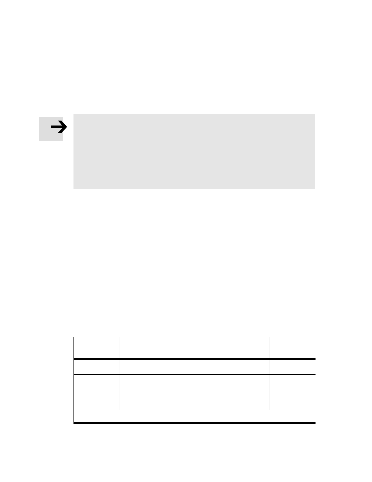
S Das VPPM−... interpretiert Sollwertsignale, die kleiner als 1 % Full scale sind
als 0 V (siehe Tabelle
druck auf Umgebungsdruck gesetzt.
S Verbinden Sie das VPPM−... mit einem Sollwertsignal.Das VPPM−... verfügt
über einen so genannten Differenzeingang". Das Sollwertsignal 0 ... 10 V wird
dabei an die Kontakte 3 und 4 angelegt, wobei das niedrigere Potenzial am
Kontakt 3 und das höhere Potenzial an
( Sollwert) kann mit Kontakt 7 (GND) verbunden werden.
Ausgangsdruckbereich). In diesem Fall wird der Arbeits
Kontakt4 anzuschließen ist. Kontakt 3
S Bestromen Sie das VPPM−... mit Gleichstrom (Versorgungsspannung UV =
24VDC ±10 %).
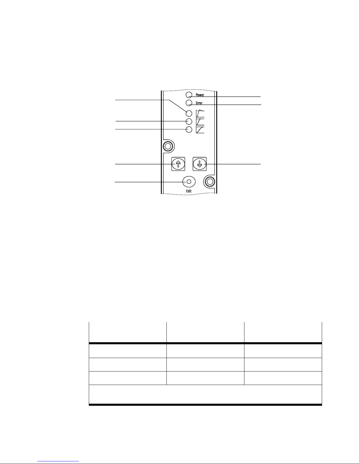
S Wählen Sie den Parametersatz für den Regler aus (siehe tech. Daten):
Drücken Sie die Taste EDIT für 3 sec.
Wählen Sie mit der Taste UP bzw. DOWN
den gewünschten Parametersatz
aus. Die LED des gewählten Parametersatzes leuchtet.
Drücken Sie erneut die EDIT−Taste zum Bestätigen ihrer Wahl.
Das Regelverhalten des VPPM kann über die digitalen Eingänge D1 und D2 auch
ferngesteuert eingestellt werden:
Parameter
satz
1 schnelles Regelverhalten 1
2 universelles Regelverhalten
3 präzises Regelverhalten 1 1
1)
1 = 24 V DC / 0 = 0 V DC
Regelverhalten Eingang D1
PIN 1
1)
0 1
(Werkseinstellung)
Eingang D2
PIN 5
1)
0
Bild17
16
Festo VPPM−... 0810b Deutsch
Page 17
VPPM−...−DE/EN
1
2
3
4
5
1
LED (gelb) für schnelles Regelverhalten
2 LED (gelb) für universelles Regelverhalten
(Werkseinstellung)
3 LED (gelb) für präzises Regelverhalten
4 Taste UP
8
7
6
5 Taste EDIT
6 Taste DOWN
7 LED (rot) ERROR
8 LED (grün) POWER
Bild18
S Belüften Sie das VPPM−... mit einem mindestens um 1 bar höheren Eingangs
druck als der maximal gewünschte Ausgangsdruck. Es stellt sich ein dazu
proportionaler Ausgangsdruck p2 ein. Dem Sollwertsignal ist dann folgender
Ausgangsdruck zugeordnet:
VPPM−...
2 bar Typ 0,02 bar
6 bar Typ 0,06 bar 6 bar
10 bar Typ 0,1 bar 10 bar
1)
FS = Full scale (1 % FS = 0,1 V bzw. 0,16 mA / 100 % FS = 10 V bzw. 16 mA)
2)
0 V bzw. 4 mA = 0 bar
Bild19
Ausgangsdruck beim
Signal 1 % FS
1) 2)
Ausgangsdruck beim
Signal 100 % FS
2 bar
1) 2)
Festo VPPM−... 0810b Deutsch
17
Page 18
VPPM−...−DE/EN
)
S Wählen Sie einen passenden Parametersatz aus:
Empfohlene Parametersätze
Schlau ch
länge
0 m 3 3 2 1
1 m 3 3 2 2
3 m 3 3 3 2
5 m 3 3 3 2
1)
bei Schlauchdurchmesser 6 mm oder 8 mm
Bild20
1
Offenes
System
6 Bedienung und Betrieb
Hinweis
S Stellen Sie sicher, dass beim Abschalten des VPPM−... zuerst der
Versorgungsdruck, danach die Sollwertspannung und zuletzt die
Versorgungsspannung abgeschaltet wird.
Ausgangsvolumen
0 ... 100 ml 100 ... 1000 ml > 1000 ml
7 Wartung und Pflege
Zur Reinigung:
S Schalten Sie zur äußeren Reinigung folgende Energiequellen ab:
Betriebsspannung
Druckluft
S Reinigen Sie bei Bedarf das VPPM−... von außen mit einem weichen Lappen.
Die zulässigen Reinigungsmittel sind eine milde Seifenwasserlösung (max. +50 °C)
oder alle werkstoffschonenden Medien.
18
Festo VPPM−... 0810b Deutsch
Page 19
VPPM−...−DE/EN
8 Ausbau
Zum Ausbau:
S Schalten Sie folgende Energiequellen ab:
Betriebsspannung
Druckluft
S Trennen Sie die jeweiligen Anschlüsse vom VPPM−...
S Demontieren Sie das VPPM−... von der Befestigungsfläche/Hutschiene.
9 Zubehör
Bezeichnung Typ
Steckdosenkabel gerade
Steckdosenkabel gewinkelt
Y−Anschlusskabel (zum Anschließen des VPPM−... an
analoge Ein−/Ausgänge)
Hutschienenbefestigung
Winkel
Anschlussblock
Bild21
SIM−M12−8GD−...−PU
NEBU−M12W8−...−N−LE8
NEBV−M12G8−KD−...−M12G5
VAME−P1−T
VAME−P1−A
VABM−P1−SF−G18−...−P3
Festo VPPM−... 0810b Deutsch
19
Page 20
VPPM−...−DE/EN
10 Sicherheitseinstellung
Kabelbruch Spannungstyp Stromtyp
Sollwert Ausgangsdruck sinkt
Versorgungsspannung letzter Wert wird gesichert. Ausgangsdruck bleibt
Bild22
11 Störungsbeseitigung
Ursache Zustand der LED Anzeigen
Unterspannung bzw.
Überspannung des Sollwertes
Hardwarefehler
Überspannung (> 30 V)
Interne Temperatur zuhoch
letzter Wert wird
auf 0 bar
ungeregelt erhalten. Mittelfristig kann sich der
Druck am Ausgang erhöhen oder verringern.
gesichert
Power LED (grün) ERROR−LED (rot)
leuchtet leuchtet
leuchtet blinkt
Unterspannung (< 18 V) dunkel dunkel
Bild23
20
Festo VPPM−... 0810b Deutsch
Page 21
VPPM−...−DE/EN
Störung Mögliche Ursache Abhilfe
VPPM−...
reagiertnicht
Durchflussmenge
zu gering
Druckanstieg
zulangsam
Druck konstant
trotz veränderter
Sollwertvorgabe
Versorgungsspannung fehlt,
POWER−LED leuchtet nicht
Sollwertspannung bzw.
Sollwertstrom fehlt
Anschluss der Versorgungs
spannung 24 VDC überprüfen
Steuergerät überprüfen,
Anschluss überprüfen
VPPM−... defekt Senden Sie das Gerät an den
Reparaturservice von Festo
Verengung des Strömungsquer
schnitts durch Anschlusstechnik
Anschlussalternativen
einsetzen
(Schwenkverschraubungen)
Großes Zylinder volumen und
lange Schlauchlänge
Bruch des Versorgungskabels
Anderen Parametersatz
wählen
Versorgungskabel ersetzten
(Der zuletzt eingestellte
Ausgangsdruck bleibt unge
regelt erhalten. Mittelfristig
kann sich der Druck am
Ausgang erhöhen oder
verringern.)
Zu geringer Versorgungs
Versorgungsdruck erhöhen
druck P1
Manuelles Aus
wählen der Para
metersätze über
UP/DOWN−Tasten
am VPPM−... nicht
möglich
Bild24
Festo VPPM−... 0810b Deutsch
Auf den digitalen Eingängen
D1 und D2 liegt Spannung an
An digitale Eingänge D1 und
D2 0 V DC anlegen
21
Page 22
VPPM−...−DE/EN
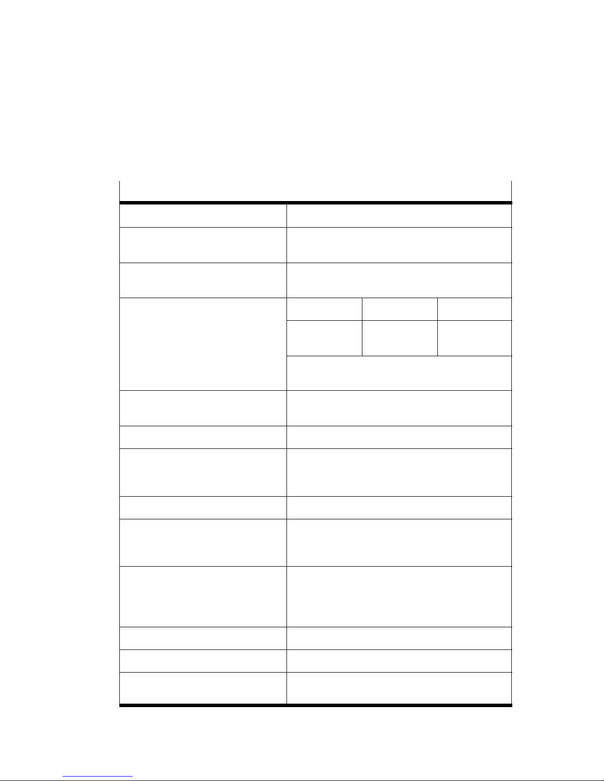
12 Technische Daten
Typ VPPM−...
Bauart Proportional Druckregelventil
Einbaulage Beliebig, vorzugsweise liegend
Medium Gefilterte ungeölte Druckluft (Filterfeinheit
Druckbereiche 2 bar Typ 6 bar Typ 10 bar Typ
(Anzeigeelemente nach oben)
min.40 m), keine Kondensation zulässig.
Zul. Eingangsdruck
Regelbereich
[bar] max. 4
0,02 ... 2
max. 8
0,06 ... 6
max. 11
0,1 ... 10
Eingangsdruck p1 mind. 1 bar über
Ausgangsdruck p2
Gesamtleckage im
[l/h] < 5
Neuzustand
Anschlüsse G1/8" (1/8 NPT)
Nennweite
Belüftung
Entlüftung
[mm]
6
4,5
Normalnenndurchfluss siehe Bild26
Schutzart IP65 im montiertem Zustand, mit angezogenen
Befestigungsschrauben, in Verbindung mit
Anschlussdose laut Zubehör.
Zul. Temperaturbereich
Umgebungstemperatur
Mediumstemperatur
Lagertemperatur
[°C]
[°C]
[°C]
0 ... +60
+10 ... +50
10 ... +70
El. Anschluss Steckkontakt M12x1, 8−polig
Zul. Betriebsspannung [V DC] 21,6 ... 26,4 (zul. Restwelligkeit max. 10 %)
Maximale elektrische
Leistungsaufnahme 7 W (bei Dynamikklasse L)
22
Festo VPPM−... 0810b Deutsch
Page 23
VPPM−...−DE/EN
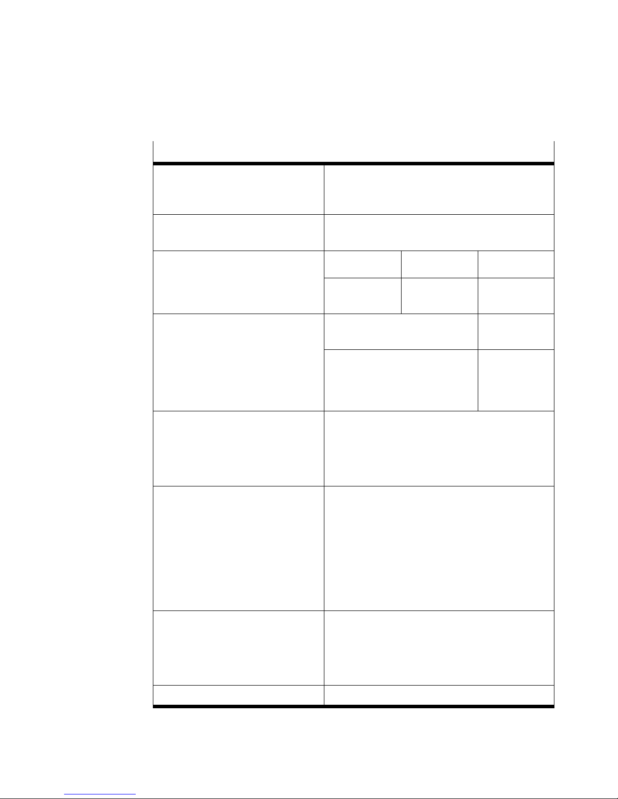
Typ VPPM−...
Belastbarbeit des digita
max. 60 mA
len Schaltausgangs D3
(PIN 8 im el. Anschluss)
Max. zul. Versorgungs−
[m] 10
und Signalleitungslänge
Regelgenauigkeit 2 bar Typ 6 bar Typ 10 bar Typ
Standard (2 %)
Klasse S1 (1 %)
Sollwertgröße
Eingangswiderstand(Soll−
0,045 bar
0,025 bar
Spannungstyp
VPPM−...−V1.−...
0 ... +10 V DC
10 k
0,135 bar
0,075 bar
0,225 bar
0,125 bar
Stromtyp
VPPM−...−A4.−...
4 ... 20 mA
250
wert)
Bürde Istwertausgang
min. 2 k
max. 500
Elektromagnetische
Verträglichkeit
EMV Störaussendung
und Störfestigkeit
Siehe Konformitätserklärung
è www.festo.com
CE−Konformität für Industriebereiche erfüllt
Schwingung und Schock
Schwingung
Schock
Werkstoffe
Gehäuse
Deckel
Dichtungen
Schmierung
Gewicht 400 g
Bild25
Festo VPPM−... 0810b Deutsch
Nachfolgende Angaben gelten nicht bei Montage
des VPPM−... an den Winkel VAME−P1−A.
Geprüft nach DIN/IEC 68/EN 60068 Teil 2−6;
bei Wandmontage:
0,35 mm Weg bei 10 ... 60Hz,
5g Beschleunigung bei 60 ... 150Hz
Geprüft nach DIN/IEC 68/EN 60068 Teil 2−27;
bei Wandmontage:
±30 g bei 11 ms Dauer; 5 Schocks je Richtung
AL−Knetlegierung
PAXMD6−GF50/gr−P; PA6−GB20,GF10/gr−P
NBR
Silikonfrei
23
Page 24
VPPM−...−DE/EN
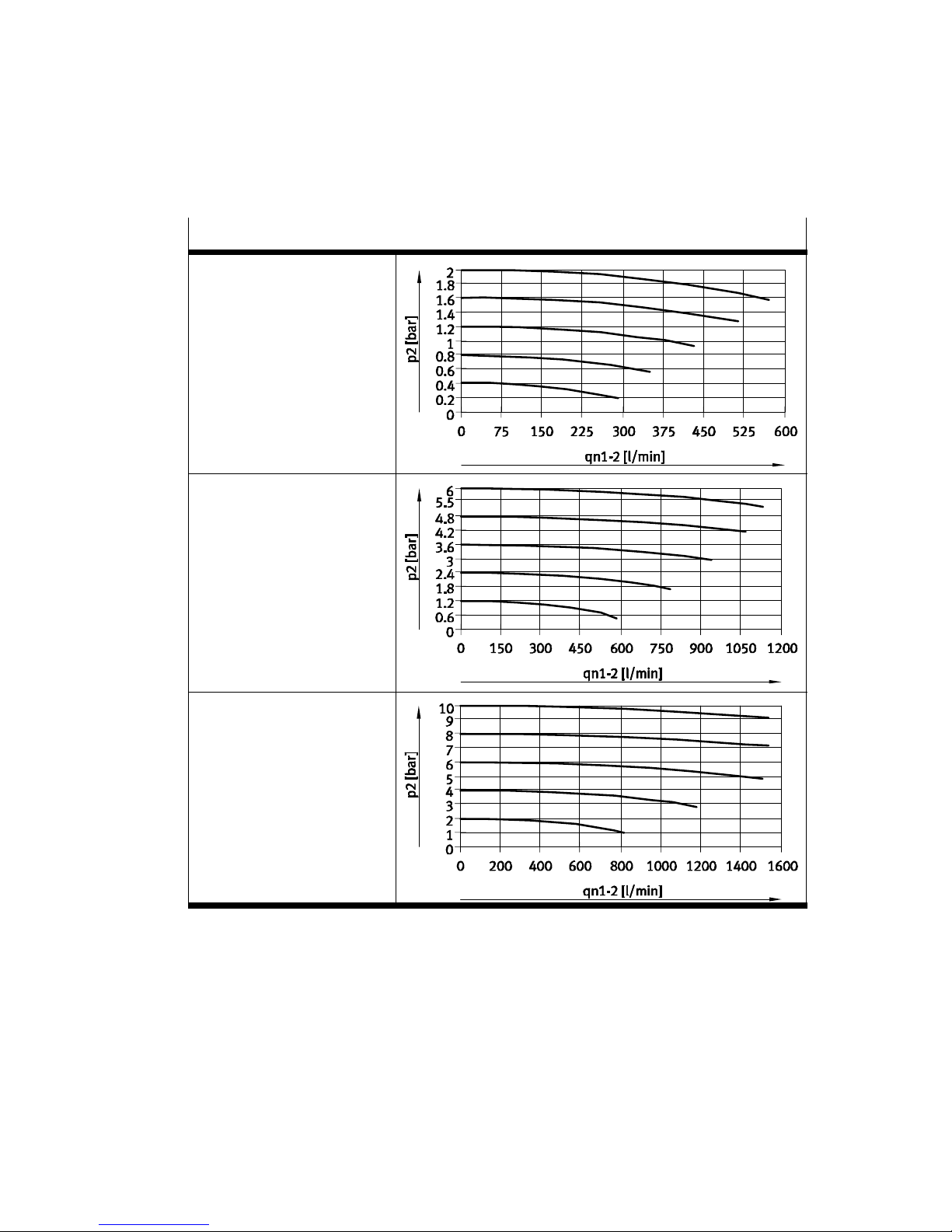
Durchflusskennlinien
2 bar Ventilvariante:
Typ VPPM−6L−...−OL2H−...
6 bar Ventilvariante:
Typ VPPM−6L−...−OL6H−...
10 bar Ventilvariante:
Typ VPPM−6L−...−OL10H−...
Bild26
24
Festo VPPM−... 0810b Deutsch
Page 25

VPPM−...−DE/EN
Proportional pressure regulator type VPPM−...English
Contents
1 Connections, operating elements and variants 24 . . . . . . . . . . . . . . . . . . . .
Operating elements and connections of the VPPM−... (in−line valve) 24 . . . . .
Pneumatic connections of the VPPM−... (flanged valve) 25 . . . . .
Variants of the VPPM−... 26 . . . . . . . . . . . . . . . . . . . . . . . . . . . . . . . . . . . .
. . . . . . . . . .
. . . .
2 Function and application 27 . . . . . . . . . . . . . . . . . . . . . . . . . . . . . . . . . . . . . . .
3 Conditions of use 27 . .
4 Fitting 28 . . . . . .
Mechanical installation 28 .
Pneumatic installation 31 . . . . . . . .
Electrical installation 31 . . . . . . . . . . . . . . . .
5 Commissioning 34 . . . . . . . . . . . . . . . . . . . . . . .
6 Operation 36 . . . . . . . . . . . . . . . . . . . . . . . . . .
7 Care and maintenance 36 . . . . . . . . . . . . . . . . . . . . . .
8 Dismantling 37 . . . . . . . . . . . . . . . . . . . . . . . . . . . . . . .
9 Accessories 37 . . . . . . . . . . . . . . . . . . . . . . . . . . . . . . .
10 Safety setting 38 . . . . . . . . . . . . . . . . . . . . . . . . . . . . . .
11 Eliminating faults 38 . . . . . . . . . . . . . . . . . . . . . . . . . . . . . .
. . . . . . . . . . . . . . . . . . . . . . . . . . . . . . . . . . . . . . . . . . .
. . . . . . . . . . . . . . . . . . . . . . . . . . . . . . . . . . . . . . . . . . . . . . . .
. . . . . . . . . . . . . . . . . . . . . . . . . . . . . . . . . . . . . . . .
. . . . . . . . . . . . . . . . . . . . . . . . . . . . . . . . .
. . . . . . . . . . . . . . . . . . . . . . . . . .
. . . . . . . . . . . . . . . . . . . . . . . .
. . . . . . . . . . . . . . . . . . . . . . . . .
. . . . . . . . . . . . . . . . . . .
. . . . . . . . . . . . . . . . . .
. . . . . . . . . . . . . . . . . . .
. . . . . . . . . . . . . . . . . .
. . . . . . . . . . . . . . .
12 Technical specifications 40 . . . . . . . . . . . . . . . . . . . . . . . . . . . . . . . . . .
Festo VPPM−... 0810b English
. . . . .
25
Page 26
VPPM−...−DE/EN
1 Connections, operating elements and variants
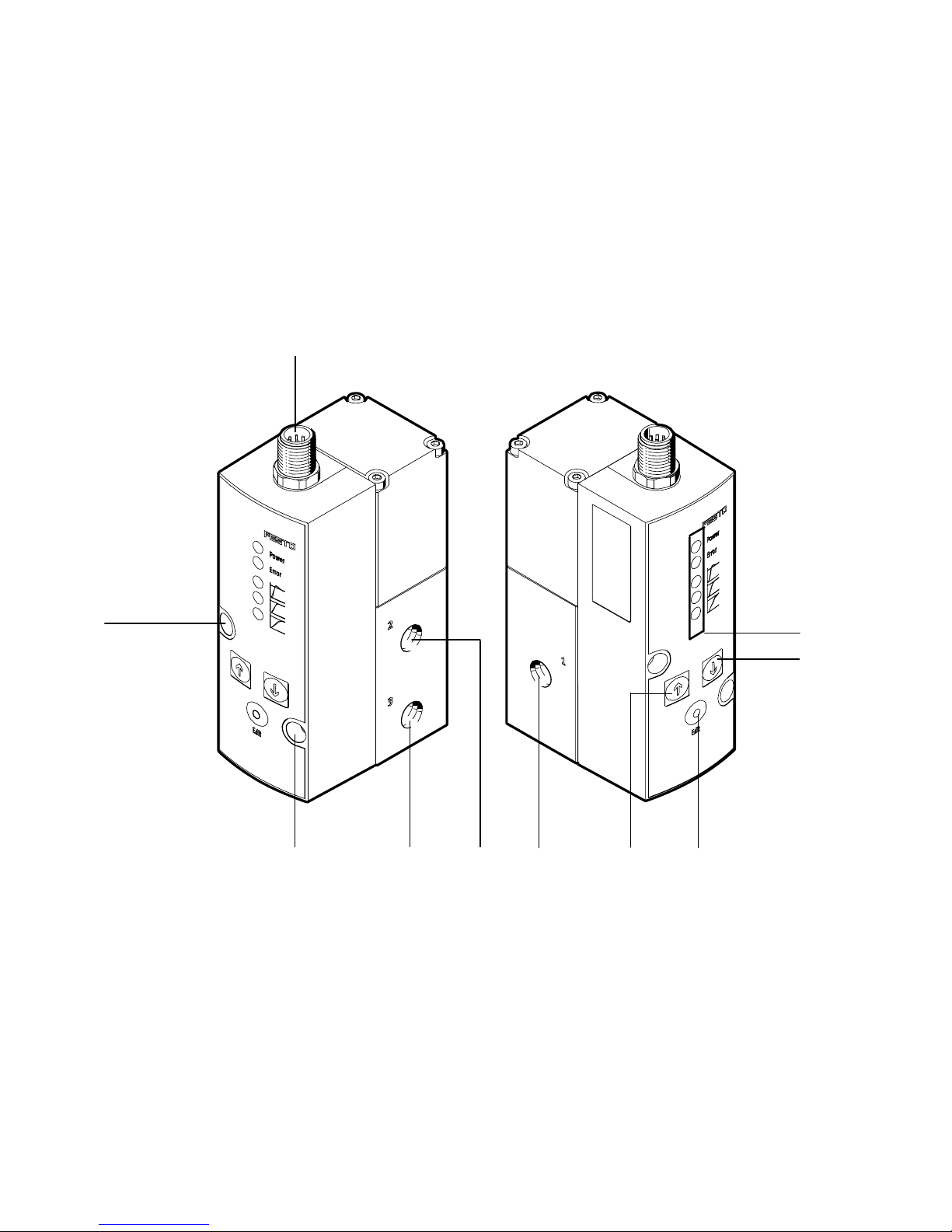
Operating elements and connections of the VPPM−... (in−line valve)
1
9
1
Plug for electrical connection (8−pin)
2 LED for operational and status displays
3 DOWN button
4 EDIT button
5 UP button
8
6 Supply port 1 (pressure input)
7 Air port 2 (pressure output)
8 Valve exhaust port 3
9 Through holes for fastening
2
3
56479
Fig.1
26
Festo VPPM−... 0810b English
Page 27
VPPM−...−DE/EN
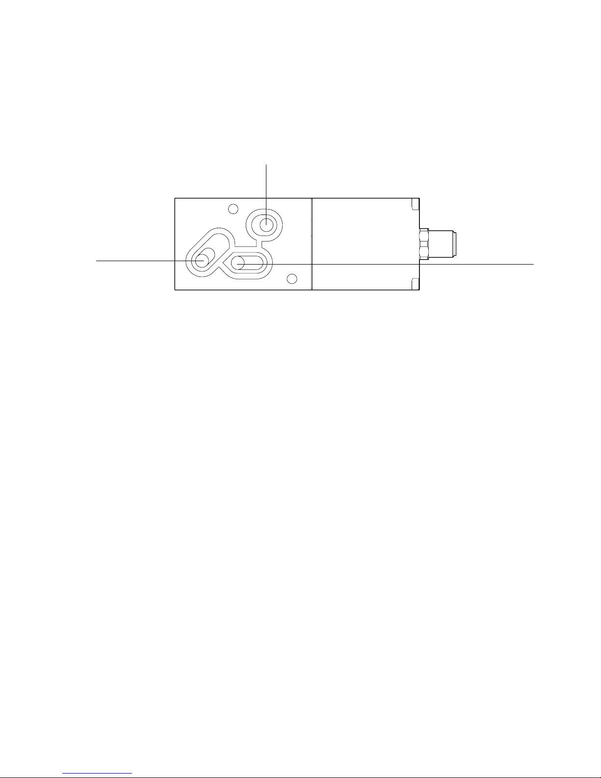
Pneumatic connections of the VPPM−... (flanged valve)
2
3
1 Compressed air channel (pressure input)
2 Air channel (pressure output)
Fig.2
1
3 Exhaust channel
Festo VPPM−... 0810b English
27
Page 28
VPPM−...−DE/EN
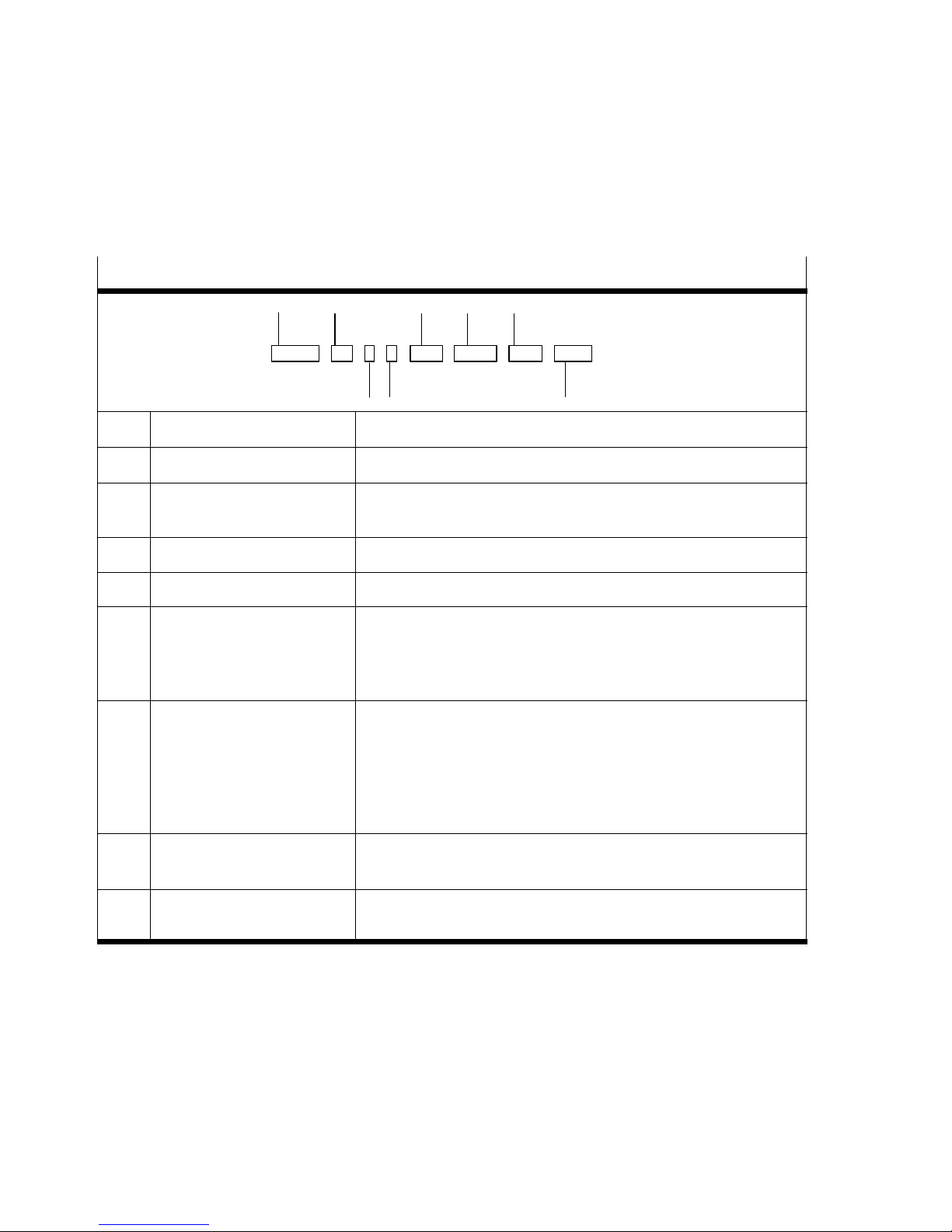
Variants of the VPPM−...
Type code of the VPPM−...
1
2
5
6
7
VPPM − 6L − L − 1 − G18 − 0L6H − V1N − S1
3
Item Features Designation
1 Pressure regulator VPPM
2 Nominal size in [mm]
Valve type
3 Dynamics class L (Low) / M (Medium) / H (High)
4 Valve function 1 (3−way pressure regulator, normally closed)
5 Pneumatic connection
Flange/sub−base
ISO thread
NPT thread
6 Standard control ranges:
Lower pressure value
Upper pressure value
Alternative control ranges:
Lower pressure value
Upper pressure value
4
6
F (flange) / L (in−line)
F
G12 (1/2") / G14 (1/4") / G18 (1/8")
N12 (NPT 1/2) / N14 (NPT 1/4) / N18 (NPT 1/8)
0L (0 bar)
2H (2 bar) / 6H (6 bar) / 10H (10 bar)
...L (... = value between 0 ... 10 bar, e.g. 4L)
...H (... = value between 0 ... 10 bar, e.g. 8H)
8
7 Setpoint specification
Switch output
8 Overall precision
Operator unit
Fig.3
28
A4 (4 ... 20 mA) / V1 (0 ... 10 V)
P (PNP) / N (NPN; Standard)
... (2 %) / S1 (1 %)
... (LED) / C1 (LCD)
Festo VPPM−... 0810b English
Page 29
VPPM−...−DE/EN
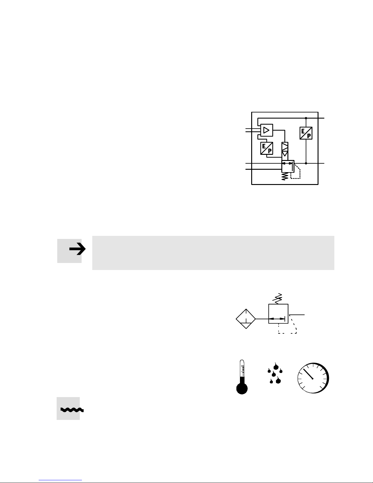
2 Function and application
The VPPM−... has been designed to regulate a
pressure proportional to a specified setpoint
value. An integrated pressure sensor records
the pressure at the working line and compares
this value to the setpoint value. In the case of
deviations between the setpoint and actual
value, the regulator is actuated until the out
put pressure
has reached the setpoint value.
3 Conditions of use
Please note
Incorrect handling can result in malfunctioning.
S Make sure that the following specifications are always observed.
S Compare the limit values contained in
these operating instructions with those of
your application (e.g. operating medium,
pressures, forces, moments, temperatures,
loads, speeds, voltages).
+W
−W
3
1
Fig.4
LF−... LR−...
X
2
S Take into consideration the ambient
conditions at the location of use.
S Please comply
safety laws and regulations.
S Remove all transport packing such as
protective wax, foils (polyamide), caps
(polyethylene), cardboard boxes.
It is intended that the packaging be
recycled on the basis of its constituent
materials (exception: oiled paper = other
waste).
S Use the product in its original state. Unauthorized modification is not
permitted.
Festo VPPM−... 0810b English
with national and local
Fig.5
[°C] [%] [mbar]
Fig.6
29
Page 30
VPPM−...−DE/EN
S Note the warnings and instructions on the product and in these operating
instructions.
S Ensure that the compressed air is properly prepared (see chapter 9 Technical
specifications").
S Slowly pressurize the complete system. This will prevent uncontrolled
movements from occurring.
4 Fitting
Mechanical installation
Please note
S Fitting and commissioning are to be carried out by qualified personnel only in
accordance with the operating instructions.
S Handle the VPPM−... with care so that the electrical connection is not
damaged. This can result reduce the operational reliability.
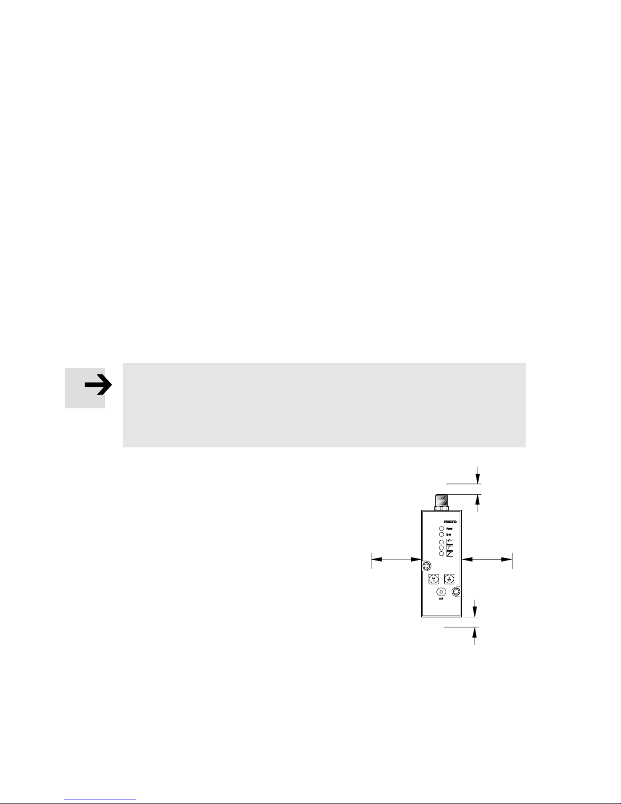
S Make sure there is sufficient space for the
cable connection and the
tube coupling.
This prevents kinks in the connecting
cable.
S Place the VPPM−... as close to the con
sumer as possible. This results in better
control precision and shorter response
times.
Fig.7
30
Festo VPPM−... 0810b English
Page 31
VPPM−...−DE/EN
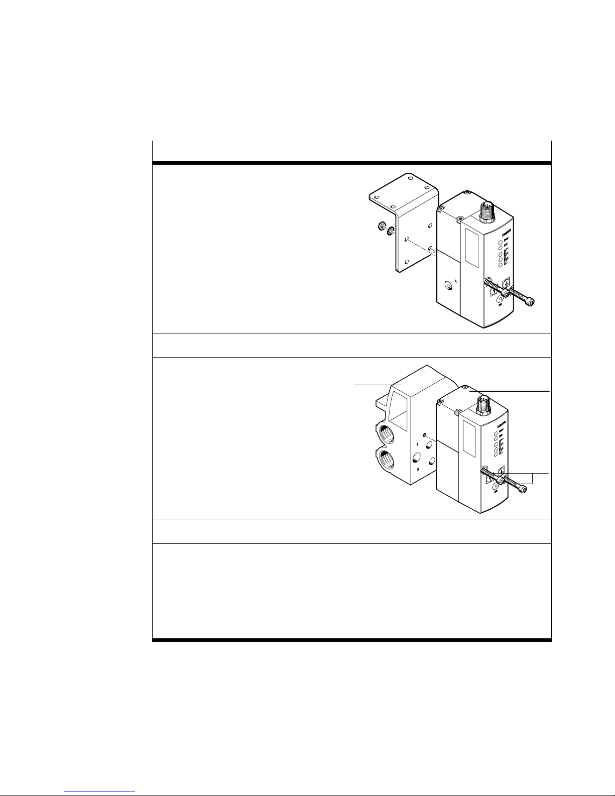
Fastening to a wall or surface
S Fasten the VPPM−... at the intended
Position of the mounting holes, see Fig.
Tightening torque: 1.0 Nm
position with two M4 screws.
If necessary, use the bracket type
VAME−P1−A (see Fig.). When mounting
the VPPM with the aid of the bracket,
the VPPM−... may only be loaded
statically.
Fastening on the sub−base
S Fasten the VPPM−... 2 on the
sub−base 1 type VABM−P1−SF−G18−...
Position of the mounting holes,
see Item 3 in the figure to the right
Tightening torque: 1.5 Nm
1
2
3
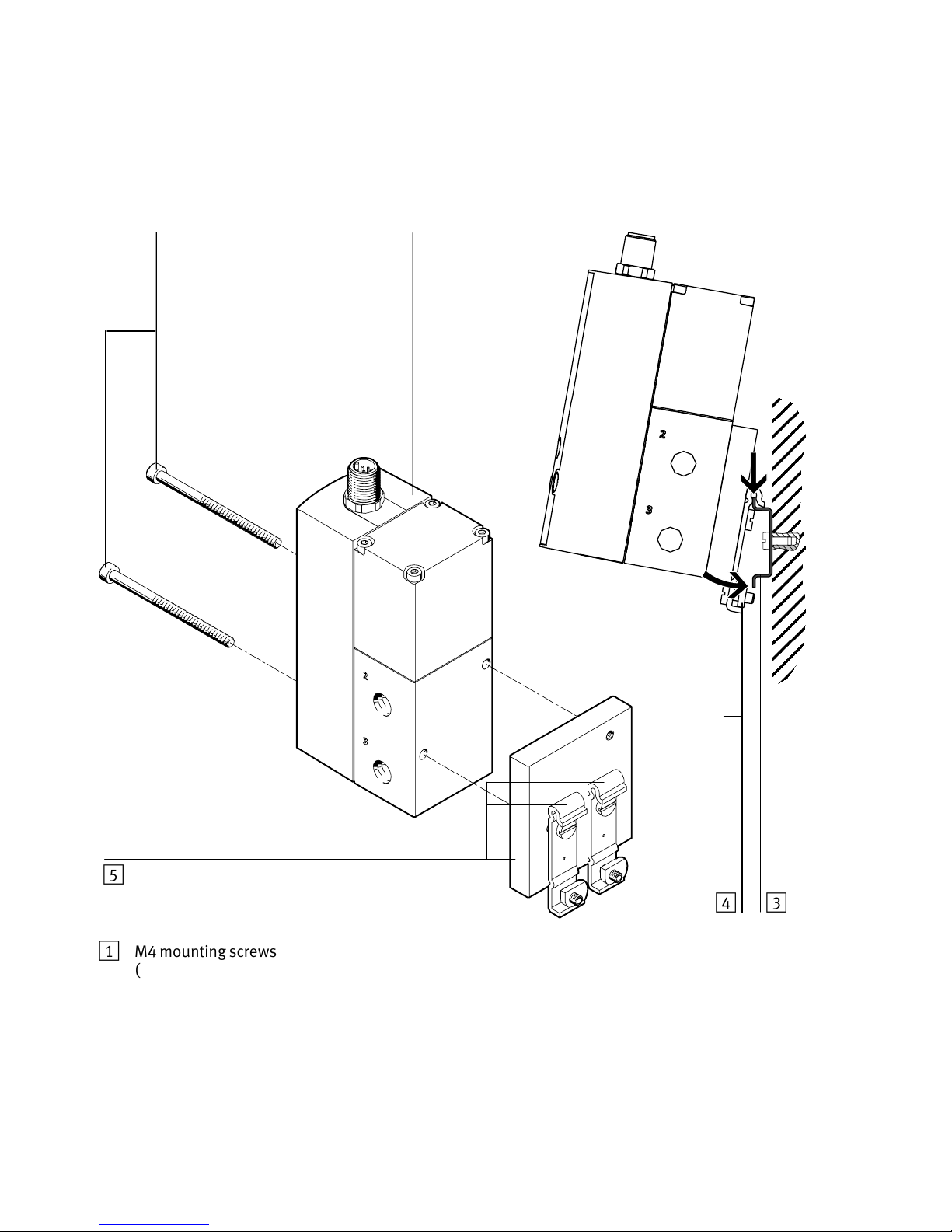
Fastening on the H−rail (see Fig.9)
S Mount the H−rail adapter type VAME−P1−T to the VPPM−... with the aid of the enclosed
screws (Tightening torque approx. 1.0 Nm):
for x": M4 x 65
for ¼": M4 x 75
S Hang the VPPM−... onto the H−rail.
S Secure the VPPM−... with the retaining screws of the H−rail adapter
(tightening torque 1.5 Nm).
Fig.8
Festo VPPM−... 0810b English
31
Page 32
VPPM−...−DE/EN
1
2
1 M4 mounting screws
(tightening torque, see Fig.8)
2 VPPM−...
3 H−rail
Fig.9
32
453
4 H−rail clamping unit
5 H−rail adapter type VAME−P1−T
Festo VPPM−... 0810b English
Page 33
VPPM−...−DE/EN
Pneumatic installation
S Remove the fastening elements from the supply ports.
S Connect the tubing of the supply port 6 and the air port 7 (see Fig.1).
Electrical installation
Warning
S Use only power units which guarantee reliable electrical isolation of the
Screw on a silencer to the exhaust port 8
.
operating voltage as per IEC/DIN EN 60204−1. Observe also the general
requirements for PELV power circuits as per IEC/DIN EN 60204−1.
Please note
Long signal cables reduce the immunity to interference.
S Make sure that the signal cable is not longer than 10 m.
S Check which valve variant you have using the rating plate:
Designation on the rating plate
VPPM−...−V1... VPPM−...−A4...
Designation Voltage variant Current variant
Electrical setpoint value 0 ... 10 V DC 4 ... 20 mA
Fig.10
S Check the use of the following options on the VPPM−...:
Measurement of the actual value of voltage or current.
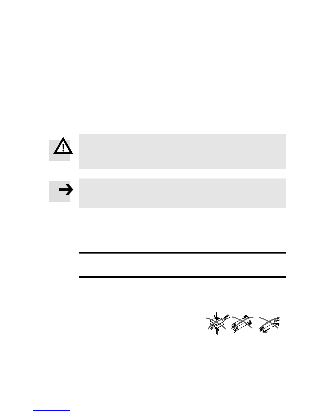
S Make sure that the cable installation is
neither squashed, bent nor stretched:
S Use the pre−assembled plug socket with
cable from Festo (see chapter 9 Acces
sories"). This ensures that the specified
protection class IP65
and EMC are ful
Fig.11
filled.
S If a screened cable is used, earth the insulation at the cable end which is
farther away from the VPPM.
Festo VPPM−... 0810b English
33
Page 34
VPPM−...−DE/EN
Please note
If the Y−connecting cable type NEBV−M12G8−KD−..−M12G5 is connected to CPX
I/O modules, the electrical isolation of the I/O modules can no longer be guar
anteed.
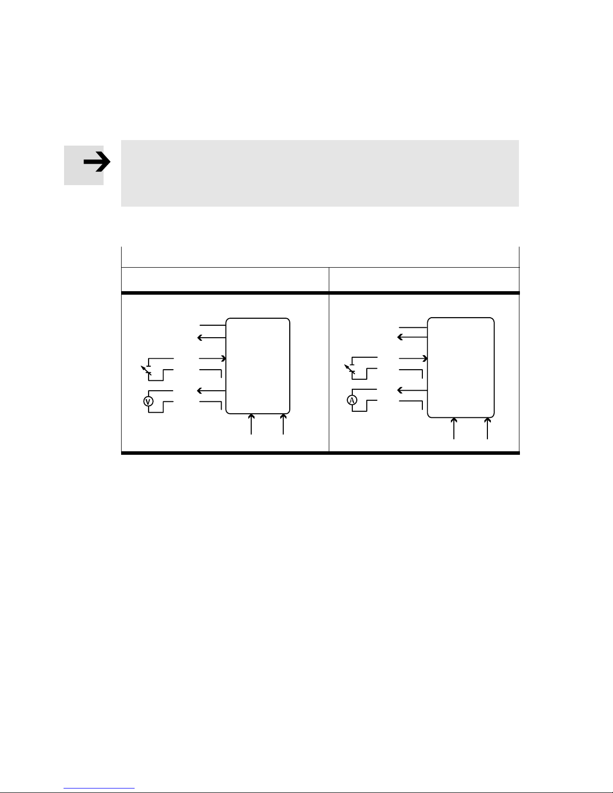
S Wire the VPPM−... according to the appropriate connection diagrams:
VPPM−... connection diagrams
Voltage variant (type VPPM−...−V1...) Current variant (type VPPM−...−V4...)
0...10 V
Fig.12
D3
U
v
out
W+
W−
X
GND
PIN
2
8
4
3
6
7
1
D1 ext in D2 ext in
PIN
U
D3
out
4...20 mA
W+
W−
GND
5
2
v
8
4
3
6
X
7
1
5
D1 ext in D2 ext in
34
Festo VPPM−... 0810b English
Page 35
VPPM−...−DE/EN
)
8
1
2
8
1
2
3
5
64
5
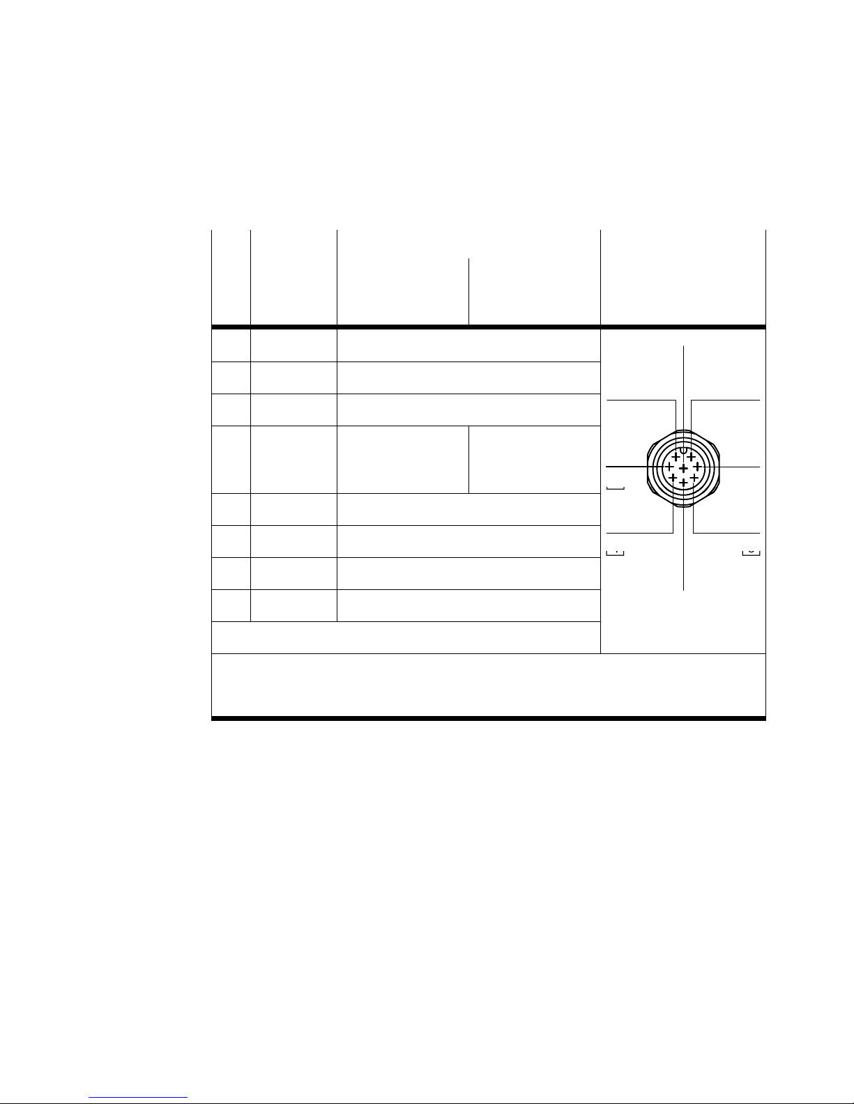
S The individual pins are assigned at the electrical connection as follows:
Pin
Cable
colours
1 White (WH) Digital input D1
2 Brown (BN) +24 V DC power supply
3 Green (GN) Analogue input W− (− setpoint value)
4 Yellow (YE) Analogue input
5 Grey (GY) Digital input D2
6 Pink (PK) Analogue output X (actual value)
7 Blue (BU) 0 V DC or GND
8 Red (RD) Digital output D3
PE braided screen on thread
Connection designation M12 plug
1
Voltage variant
type
VPPM−...−V1...
W+ (+ setpoint
value) 0 ... 10 V
Current variant
type
VPPM−...−A4...
Analogue input
W+ (+ setpoint
value) 4 ... 20 mA
3)
2)
7
3
64
1)
Using the connection socket with cable as specified in the chapter Accessories"
2)
The max. tightening torque is 0.5 Nm.
3) The hysteresis of the digital comparator output D3 is 0.5% Fs.
Fig.13
Festo VPPM−... 0810b English
35
Page 36
VPPM−...−DE/EN
3
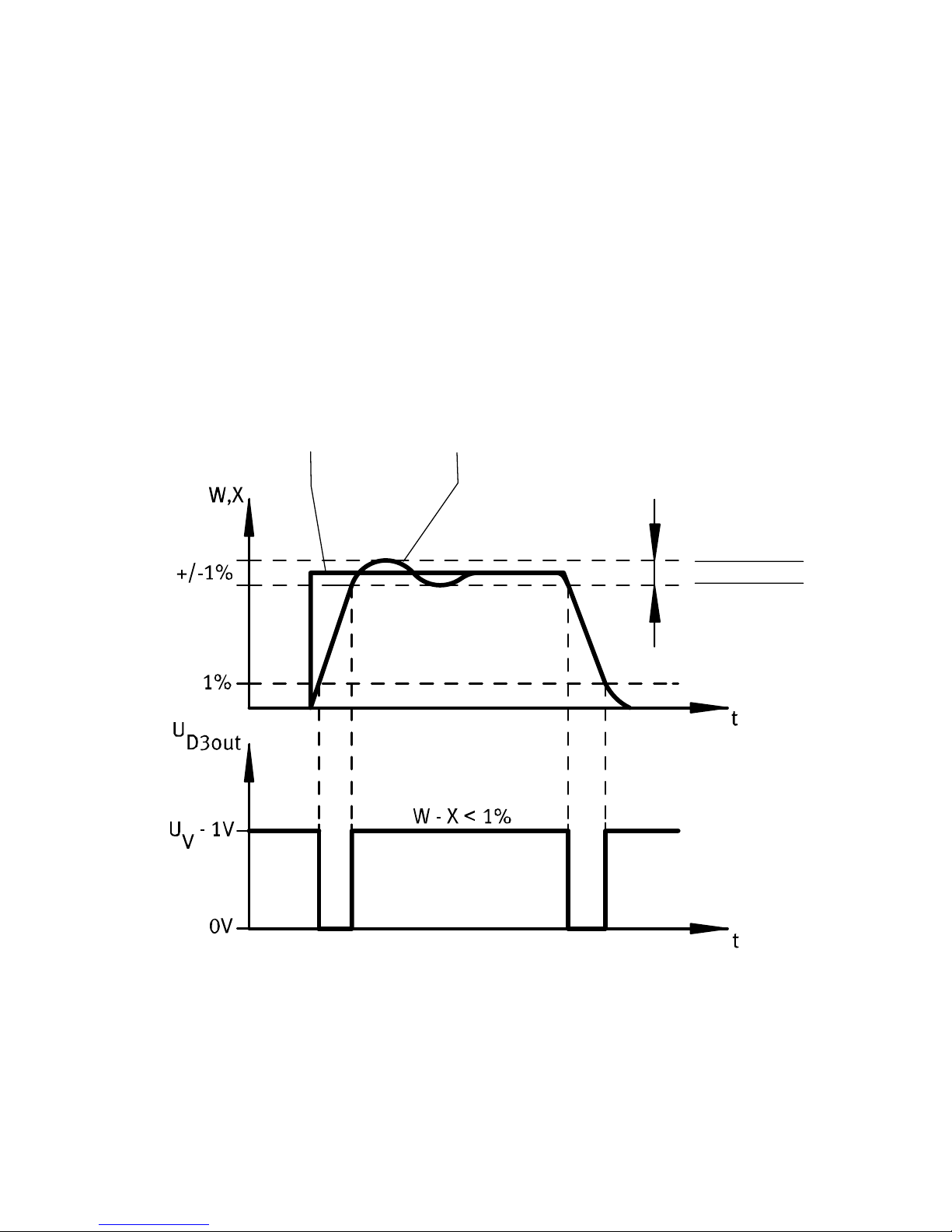
Digital comparator output D3
The function "Pressure reached" enables monitoring of the pressure regulating
function.The target value is compared here with the actual value.
The digital switching output D3 becomes active as soon as the deviation from the
target value amounts to ˚ 0.5% FS (full scale) and becomes inactive when the
deviation
Diagram of switching variant PNP
from the target value exceeds > 1%FS.
12
1 Target value
2 Actual value
4
3 Upper tolerance limit
4 Lower tolerance limit
Fig.14: P−variant (PNP)
36
Festo VPPM−... 0810b English
Page 37
VPPM−...−DE/EN
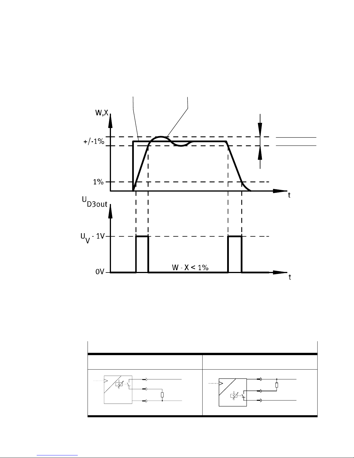
Diagram of switching variant NPN
12
3
4
1 Target value
2 Actual value
Fig.15: N−variant (NPN)
VPPM−... circuit diagrams Switch output
PNP NPN
P
PNP
Fig.16
Festo VPPM−... 0810b English
3 Upper tolerance limit
4 Lower tolerance limit
2
2
BN
RD
8
BU
7
R
+24 V
L
0 V
P
NPN
BN
R
RD
8
7
BU
+24 V
L
0 V
37
Page 38
VPPM−...−DE/EN
5 Commissioning
Please note
S Make sure that high frequency irradiation (e.g. from wireless devices, mobile
phones or other interference−emitting devices) is kept away from the
VPPM−... This prevents increased increased tolerances of the output pressure
(see data on EMC in the chapter 12 Technical specifications").
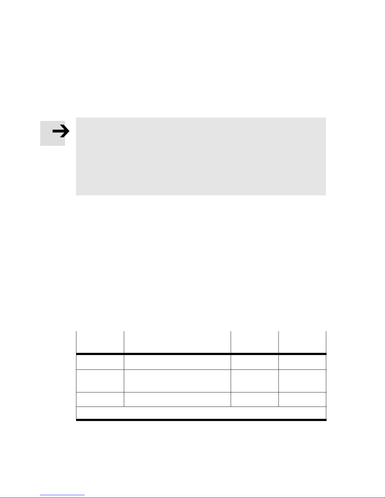
S The VPPM−... interprets setpoint signals less than 1 %
full scale to be 0 V
(see Output pressure range" table). In this case the working pressure is set
at the ambient pressure.
S Connect the VPPM−... with a setpoint signal. The VPPM−... has what is called a
differential input". The setpoint signal 0 ... 10 V is applied to contacts 3 and
4. The lower potential must be connected at contact 3 and the higher potential
at contact4. Contact 3 ( setpoint value) can be connected to contact 7 (GND).
S Supply the VPPM−... with direct current (power supply UV = 24 VDC ±10 %).
S Select the parameter set for the regulator (see Technical
specifications"):
Press the EDIT button for 3 sec.
Use the UP or DOWN button to select the required parameter set. The LED
of the selected parameter set lights up.
Press the EDIT button again to confirm your selection.
The control behaviour of the VPPM can also be set by remote control via the
digital
inputs D1 and D2.
Parameter
set
Control behaviour Input D1
PIN 1
Input D2
PIN 5
1 Fast control behaviour 1
2 Universal control behaviour
(factory setting)
3 Precise control behaviour 1 1
1)
1 = 24 V DC / 0 = 0 V DC
Fig.17
38
1)
0 1
Festo VPPM−... 0810b English
1)
0
Page 39
VPPM−...−DE/EN
1
2
3
4
5
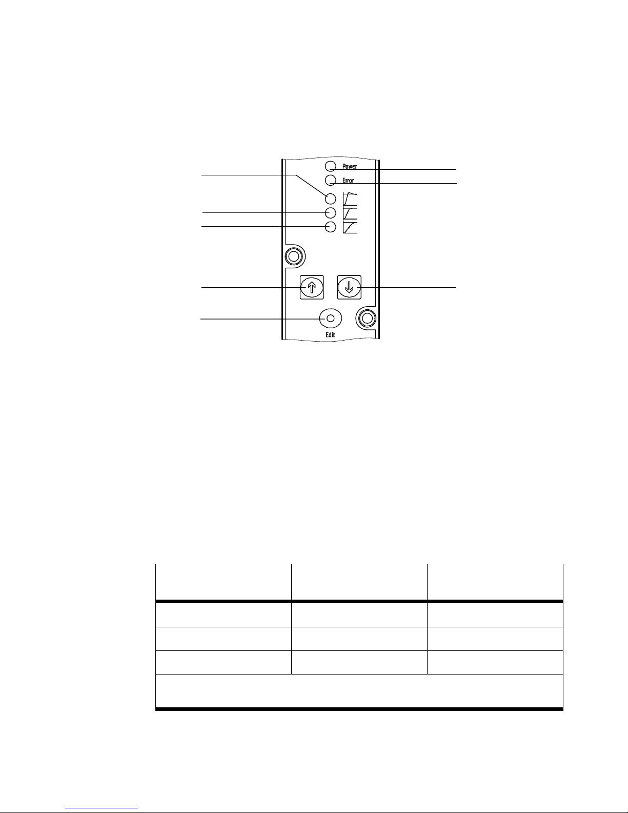
1
LED (yellow) for fast control behaviour
2 LED (yellow) for universal control behaviour
(factory setting)
3 LED (yellow) for precise control behaviour
4 UP button
8
7
6
5 EDIT button
6 DOWN button
7 ERROR LED (red)
8 POWER LED (green)
Fig.18
S Pressurise the VPPM−... with an input pressure at least 1 bar higher than the
maximum required output pressure. An output pressure propotional to this,
p2, is reached. The following output pressure is assigned to the setpoint
signal:
VPPM−...
2 bar type 0.02 bar 2 bar
6 bar type 0.06 bar 6 bar
10 bar type 0.1 bar 10 bar
1)
FS = Full scale (1 % FS = 0.1 V or 0.16 mA / 100 % FS = 10 V or 16 mA)
2)
0 V or 4 mA = 0 bar
Fig.19
Output pressure for
signal 1 % FS
1) 2)
Output pressure for
signal 100 % FS
1) 2)
Festo VPPM−... 0810b English
39
Page 40
VPPM−...−DE/EN
)
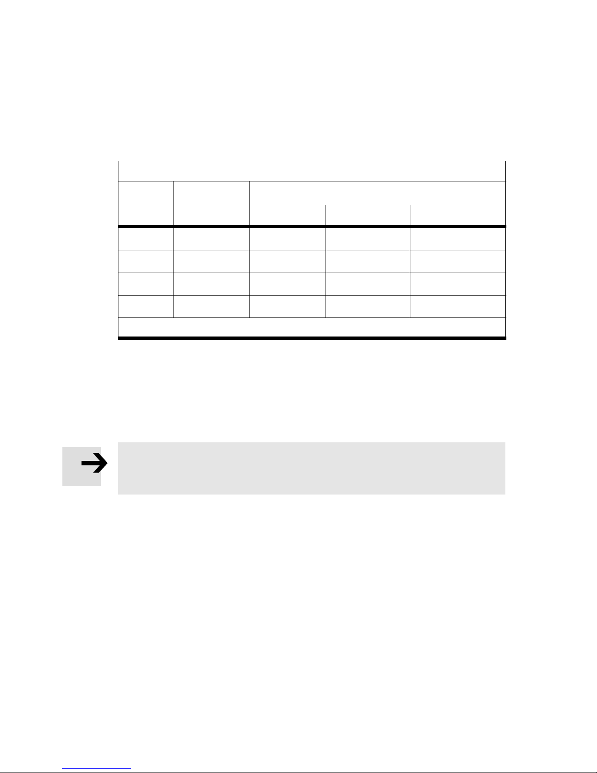
S Select an appropriate parameter set:
Recommended parameter sets
Tube
length
0 m 3 3 2 1
1 m 3 3 2 2
3 m 3 3 3 2
5 m 3 3 3 2
1)
Fig.20
1
For a tube diameter of 6 mm or 8 mm
6 Operation
Please note
S When switching off the VPPM−..., make sure that first the supply pressure,
then the setpoint voltage and finally the supply voltage are switched off.
Open
system
Output volume
0 ... 100 ml 100 ... 1000 ml > 1000 ml
7 Care and maintenance
Cleaning:
S Switch off the following sources of energy before cleaning the exterior of the
unit:
operating voltage
compressed air.
S If the VPPM−... is dirty, clean the exterior with a soft cloth.
The approved cleaning agent is a mild soap water solution (max. +50 °C) or all
media that are non−abrasive.
40
Festo VPPM−... 0810b English
Page 41
VPPM−...−DE/EN
8 Dismantling
Dismantling:
S Switch off the following sources of energy:
operating voltage
compressed air.
S Disconnect the relevant connections from the VPPM−...
S Remove the VPPM−... from the mounting surface/H−rail.
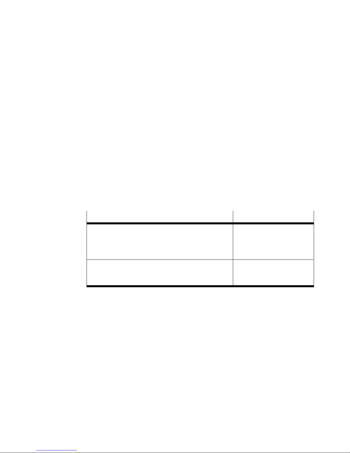
9 Accessories
Designation Type
Plug socket with cable, straight
Plug socket with cable, angled
Y−cable (to connect the VPPM−... to analogue
inputs/outputs)
H−rail mounting
Bracket
Sub−base
Fig.21
SIM−M12−8GD−...−PU
NEBU−M12W8−...−N−LE8
NEBV−M12G8−KD−...−M12G5
VAME−P1−T
VAME−P1−A
VABM−P1−SF−G18−...−P3
Festo VPPM−... 0810b English
41
Page 42
VPPM−...−DE/EN
10 Safety setting
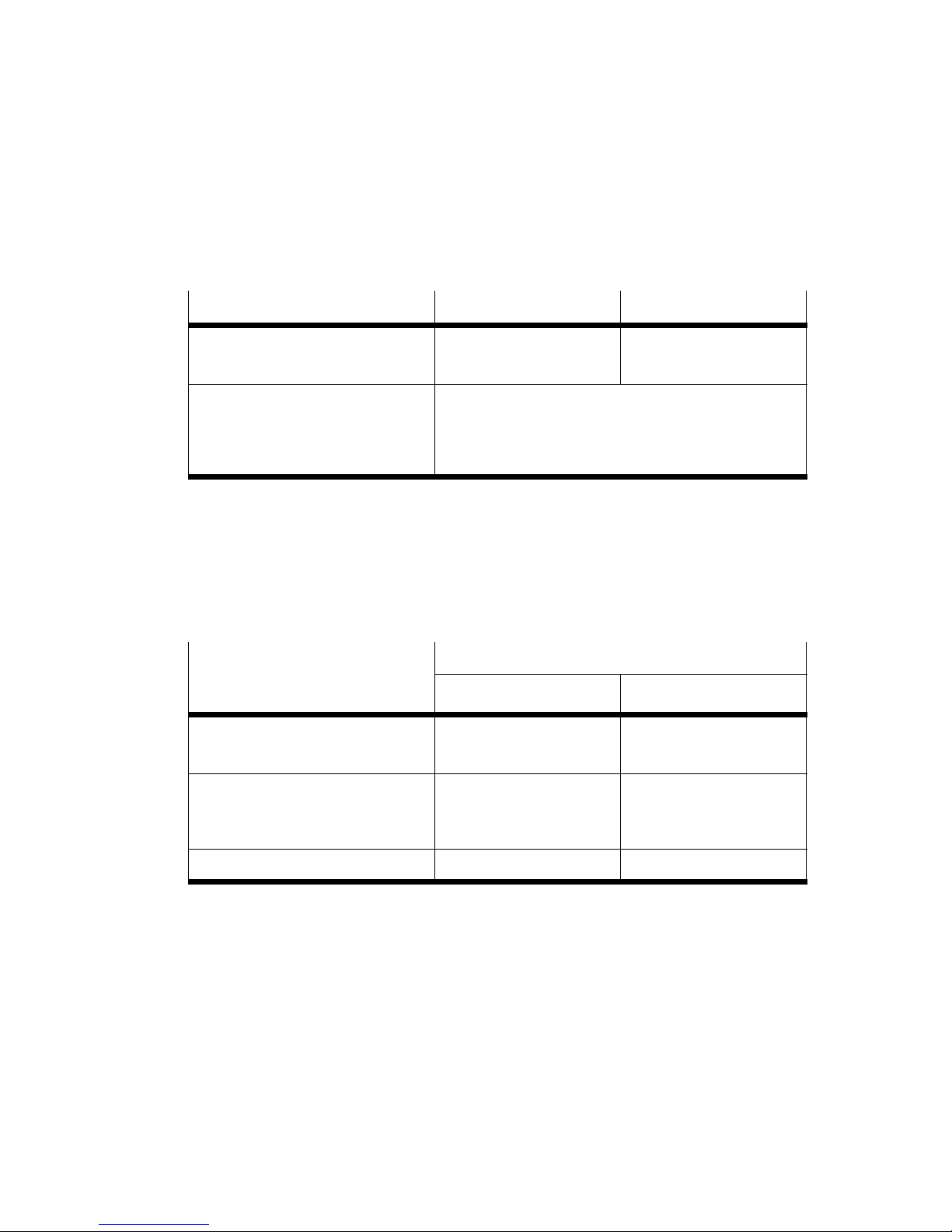
Cable fracture Voltage type Current type
Setpoint value Output pressure falls to
Supply voltage Last value is protected. Output pressure is
Fig.22
11 Eliminating faults
Cause Status of the LED displays
Undervoltage or overvoltage
of the setpoint value
Hardware fault
Overvoltage (> 30 V)
Internal temperature too high
Last value is protected.
0 bar.
maintained but without closed−loop control. The
pressure at the output can increase or decrease
over the medium term.
Power LED (green) ERROR LED (red)
Lights up Lights up
Lights up Flashing
Undervoltage (< 18 V) Out Out
Fig.23
42
Festo VPPM−... 0810b English
Page 43
VPPM−...−DE/EN
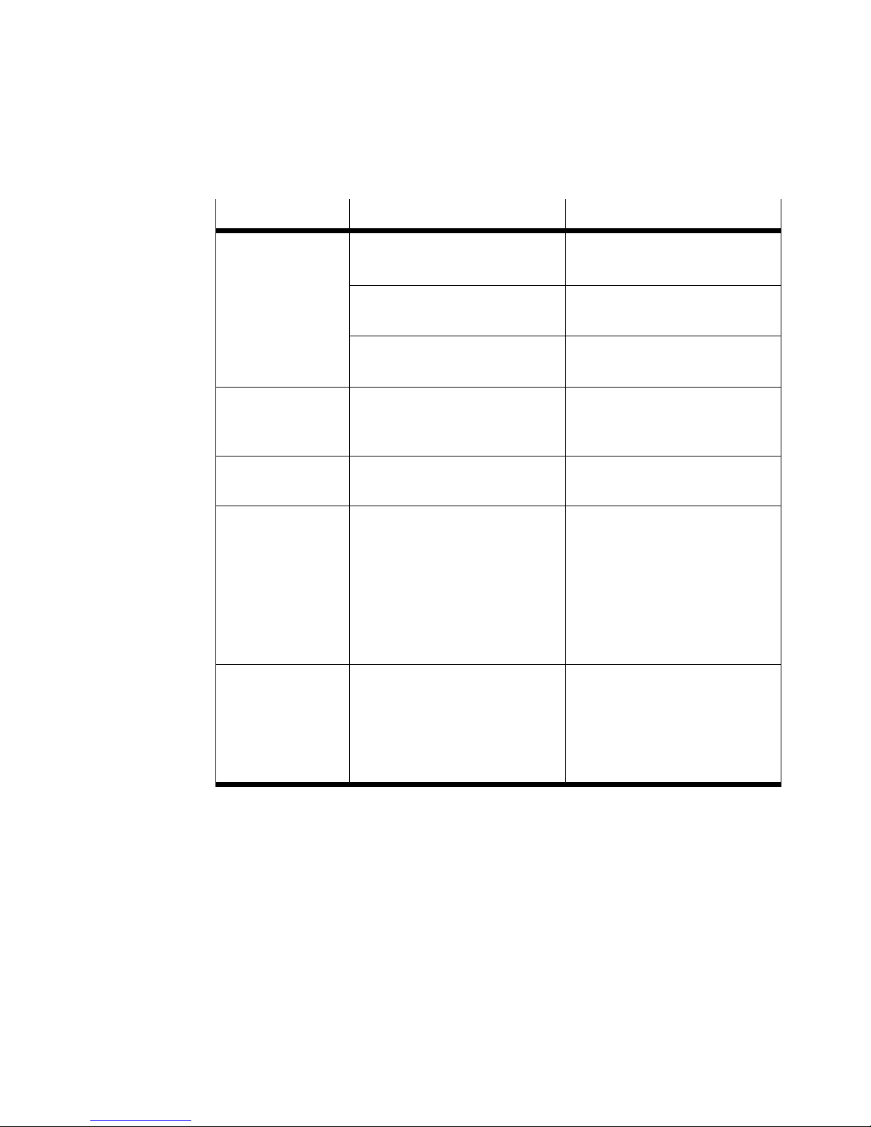
Fault Possible cause Remedy
VPPM−...
does not react
No power supply, POWER LED
does not light up.
No setpoint voltage or setpoint
current.
VPPM−... defective. Send in the device to the Festo
Flow rate too low Restricted cross section of flow
due to connection technology
(swivel fittings).
Pressure rises too
slowly
Pressure constant
despite modified
setpoint
specification
Large cylinder volume and long
tube length
Fracture of the supply cable
(The output pressure last set
is maintained but without
closed−loop control. The
pressure at the output can
increase or decrease over
the medium term.)
Supply pressure P1 too low
Check the connection of
the 24 VDC power supply.
Check controller, check
connection.
repair service.
Use connection alternatives.
Select different parameter
set
Replace supply cable
Increase supply pressure
Manual selection
of the parameter
sets using the
UP/DOWN buttons
on the VPPM−...
not possible
Fig.24
Festo VPPM−... 0810b English
Voltage is applied to the
digital inputs D1 and D2.
Apply 0 V DC to digital inputs
D1 and D2.
43
Page 44
VPPM−...−DE/EN
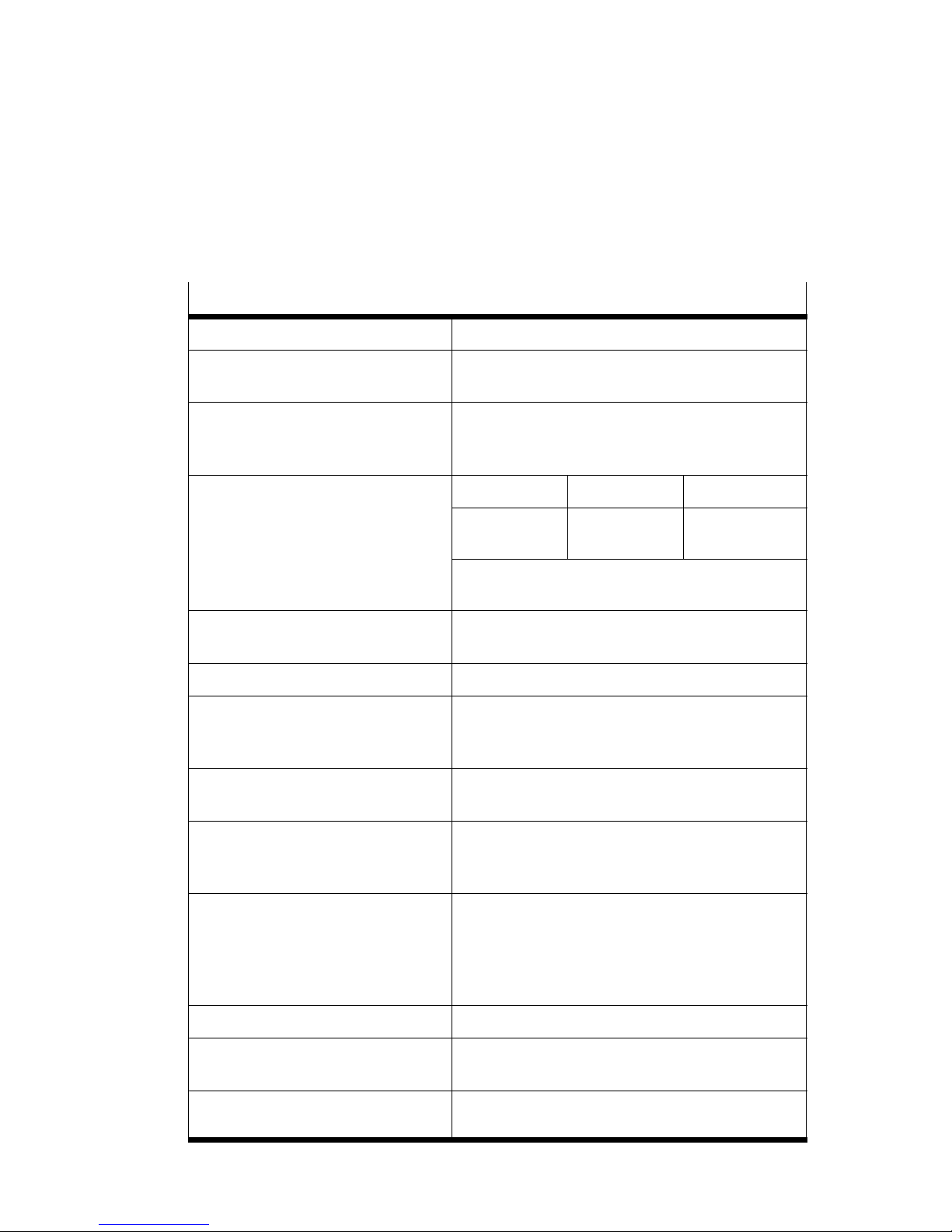
12 Technical specifications
Type VPPM−...
Design Proportional pressure regulator
Installation position As desired, preferably horizontal
Medium Filtered, unlubricated compressed air
Pressure ranges 2 bar type 6 bar type 10 bar type
(display elements facing up)
(grade of filtration min. 40 m), condensation
not permitted.
Perm. input pressure
Control range
[bar]
max. 4
0.02 ... 2
max. 8
0.06 ... 6
max. 11
0.1 ... 10
Input pressure p1 at least 1 bar above output
pressure p2
Overall leakage in new
[l/h] < 5
condition
Connections G1/8" (1/8 NPT)
Nominal size
Ventilation
Exhaust
[mm]
6
4.5
Standard nominal flow
rate see Fig.26
Protection class IP65 when mounted, with tightened mounting
screws, in connection with connection socket
according to Accessories".
Permissible temperature
range
Ambient temperature
Medium temperature
Storage temperature
[°C]
[°C]
[°C]
0 ... +60
+10 ... +50
10 ... +70
Electrical connection Crimp connector M12x1, 8−pin
Permissible operating
voltage
Maximum electrical power
consumption
44
[V DC] 21.6 ... 26.4 V DC (permissible residual ripple
max.: 10 %)
7W (with dynamic class L)
Festo VPPM−... 0810b English
Page 45
VPPM−...−DE/EN
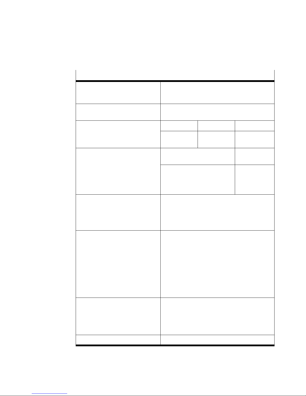
Type VPPM−...
Load capacity of the digital
max. 60 mA
switch output D3 (PIN 8 in
the el. connection)
Max. permissible supply
[m] 10
and signal line length
Control precision 2 bar type 6 bar type 10 bar type
Standard (2 %)
Class S1 (1 %)
Setpoint variable
[bar] 0.045
0.025
Voltage type
VPPM−...−V1.−...
0 ... +10 V DC
0.135
0.075
0.225
0.125
Current type
VPPM−...−A4.−...
4 ... 20 mA
Input resistance (setpoint
value)
Load of actual value output
10 k
min. 2 k
250
max. 500
Electromagnetic compati
bility
EMC interference
emission and immunity
to interference
See declaration of conformity
è www.festo.com
CE conformity fulfilled for industrial areas.
Vibration and shock
The following data does not apply to mounting
the VPPM−... to the bracket VAME−P1−A.
Vibration
Shock
tested as per DIN/IEC 68/EN 60068 parts 2−6;
tested as per DIN/IEC 68/EN 60068 parts 2−27;
Materials
Housing
Cover
Seals
Lubrication
Al wrought alloy
PAXMD6−GF50/gr−P; PA6−GB20,GF10/gr−P
NBR
Silicone−free
Weight 400 g
Fig.25
for wall mounting:
0.35 mm path at 10 ... 60Hz;
5g acceleration at 60 ... 150Hz
for wall mounting:
±30 g at 11 ms duration;
5 shocks per direction
Festo VPPM−... 0810b English
45
Page 46
VPPM−...−DE/EN
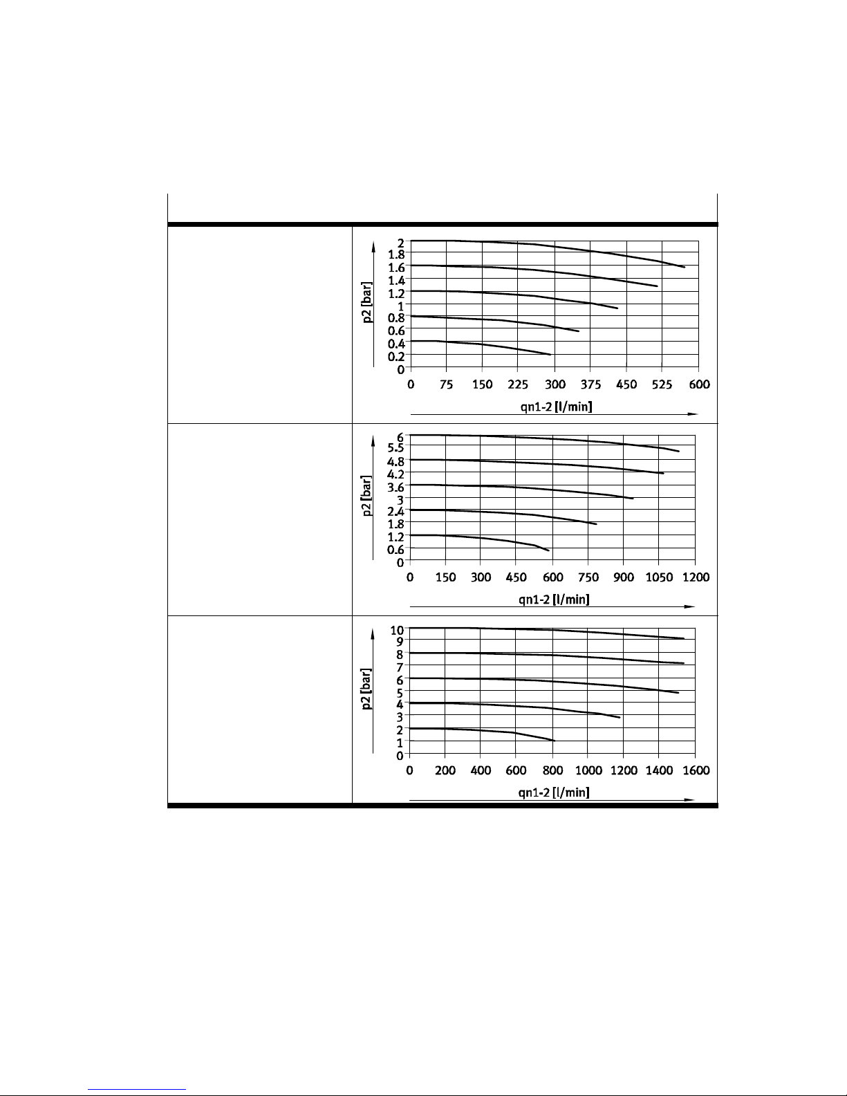
Characteristic curves for flow rate
2 bar valve variant:
type VPPM−6L−...−OL2H−...
6 bar valve variant:
type VPPM−6L−...−OL6H−...
10 bar valve variant:
type VPPM−6L−...−OL10H−...
Fig.26
46
Festo VPPM−... 0810b English
Page 47

VPPM−...−DE/EN
Festo VPPM−... 0810b
47
Page 48

VPPM−...−DE/EN
EFesto AG&Co. KG
D−73726 Essli
l@fest
Weitergabe sowie Vervielfältigung dieses Dokuments,
Verwertung und Mitteilung seines Inhalts sind verboten,
soweit nicht ausdrücklich gestattet. Zuwiderhandlungen
verpflichten zu Schadenersatz. Alle Rechte sind für den Fall
der Patent−, Gebrauchsmuster oder Geschmacks−
mustereintragung vorbehalten.
The reproduction, distribution and utilization of this docu
ment as well as the comunication of its contents to others
without express authorization is prohibited. Offenders will
be held liable for the payment of damages. All rights re
served in the event of the grant of a patent, utility module
or design.
48
Copyright:
EFesto AG&Co. KG,
Postfach
ngen
Phone:
+49/711/ 347−0
Fax:
+49/ 711/ 347− 2144
e−mail:
service_internationa
Internet:
http://www.festo.com
Original: de
Version: 0810b
Festo VPPM−... 0810b
,
o.com
 Loading...