


CPX terminal
Electronics
Manual
CPX−I/O modules
sub−bases
pneumatic
interfaces and
MPA electronic
modules
Types:
CPX−...DE−...
CPX−...DA
CPX−8DE−8DA
CPX−AB−...
VMPA−FB−EPL−...
CPX−GP−...
VABA−10S6−X1
VMPA...−FB−EM...
Manual
526 440
en 05602d
[699 181]


Contents and general instructions
Original de. . . . . . . . . . . . . . . . . . . . . . . . . . . . . . . . . . . . . . .
Edition en 05602d. .
DesignationP.BE−CPX−EA−EN. . . . . . . . . . . . . .
. . . . . . . . . . . . . . . . . . . . . . . . . . . . . . .
. . . . . . . . . . .
Order no. 526 440. . . . . . . . . . . . . . . . . . . . . . . . . . . . . . . . .
E
(Festo AG & Co. KG, D73726 Esslingen, Federal Republic of
Germany, 2006)
Internet: http://www.festo.com
E−Mail: service_international@festo.com
The reproduction, distribution and utiliz
ation of this document
as well as the communicaton of its contents to others without
express authorization is prohibited. Offenders will be held
liable for the payment of damages. All rights reserved in the
event of the grant of a patent, utility module or design.
Festo P.BE−CPX−EA−EN en 05602d
I

Contents and general instructions
CAGE CLAMP® is a registered trade mark of WAGO Kontakttechnik GmbH,
32385 Minden, Germany
TORX® is a registered trade mark of CAMCAR TEXTRON IN
C.,
Rockford, Ill., USA
HARAX® is a registered trade mark of HARTING Deutschland GmbH,
32381 Minden, Germany
SPEEDCON® is a registered trade mark of
PHOENIX CONTACT GmbH &
Co.KG, 32825 Blomberg, Germany
II
Festo P.BE−CPX−EA−E N en 05602d

Contents and general instructions
Contents
Designated use VII . . . . . . . . . . . . . . . . . . . . . . . . . . . . . . . . . . . . . . . . . . . . . . . . . . . . . . . .
Target group VIII . . . . . . . . . . . . . . . . . . . . . . . . . . . . . . . . . . .
Service VIII . . . . . . . . . . . . . . . . . . . . . . . .
Important user instructionsIX .
Notes on the
Structure of a CPX terminal XII . . . . . . . . . . . . . . . . . . . . . . . . . . . . . . . . . . . . . . . . . . . . . .
CPX pneumatic interfaces and MPA pneumatic modules XIII . . . . . . . . . . . . . . . . . . . . . . .
CPX I/O mo
Diagnosis via the field bus XIV . . . . . . . . . . . . . . . . . . . . . . . . . . . . . . . . . . .
use of this manual XI . . . . . . . . . . . . . . . . . . . . . . . . . . . . . . . . . . . . . . . . . . .
dules XIII . . . . . . . . . . . . . . . . . . . . . . . . . . . . . . . . . . . . . . . . . . . . . . . . . . . . . . .
. . . . . . . . . . . . . . . . . . . . . . . . . . . . . . . . . . . . . . .
. . . . . . . . . . . . . . . . . . . . . . . . . . . . . . . . . . . . . . . . . . . . .
. . . . . . . . . . . . . . . . . . . . . . .
. . . . . . . . . . . .
1. Pneumatic interfaces 1−1 . . . . . . . . . . . . . . . . . . . . . . . . . . . . . . . . . .
1.1 Function of the pneumatic interfaces 1−3 . . . . . . . . . . . . . . . . . . . . . . . . . . . . .
1.1.1 Display and connecting elements1−5 . . . . . . . . . . . . . . . . . . . . . . . . . . .
1.2 Fitting 1−8 . . . . . .
1.3Settings for configuring the pneumatics 1−9 . . . . . . . . . . . . . . . . . . . . . . . . . . . . .
1.4 Installation 1−1
1.5 Instructions on commissioning 1−15 . . . . . . . . . . . . . . . . . . . . . . . . . . . . . . . . . . . .
1.6 Diagnosis 1
1.6.1 Fault messages of the pneumatic interfaces 1−20 . . . . . . . . . . . . . . . . . .
1.6.2 LED display 1−21 . . . . . . .
1.6.3Fault treatment and parametrizing 1
2. MPA pneumatic modules 2−1 . . . . . . . . . . . . . . . .
2.1 Function of the MPA pneumatic modules 2−4 . . . . . . . . . . . . .
2.1.1 Display and connecting elements2−6 . . . . . . . . . . . . . . . . . . . . . . . . .
2.2 Fitting 2−7 . . . . . . . . . . . . . . . . . . . . . . . . . . . . . . . . . . . . . . . . . . . .
2.3 Installation 2−11 . . . . . . . . . . . . . . . . . . . . . . . . . . . . . . .
2.4 Instructions on commissioning 2−15 . . . . . . . . . . . . . . . . . .
2.5 Diagnosis 2−18 . . . . . . . . . . . . . . . . . . . . . . . . . . . . . .
2.5.1 Error messages of the MPA pneumatic modules 2−18 . . . . . . . . . . . .
2.5.2 LED display 2−19 . . . . . . . . . . . . . . . . . . . . . . . . . . . . . . . . . . . . . . . . .
2.5.3 Error treatment and parametrizing 2−22 . . . . . . . . . . . . . . . . . . . . . . . . . .
. . . . . . . . . . . . . . . . . . . . . . . . . . . . . . . . . . . . . . . . . . . . . . . . . .
. . . . . . . . . . . . . . . . . . . . . . . . . . . . . . . . . . . . .
. . . . . . . . . . . . . . . . . . . . . . . .
. . . . . . . . . . . . . . . . . . . . .
. . . . . . . . . . . . . . . . . .
. . . . . . . . . . . . . . . . . . . . . . .
. . . . . . . . .
. .
. . . . . . . . . . . . . . .
. .
. . . . . . . . . . . .
. . .
. . .
4 . . . . . . . . . . . . . . . . . . . . . . . . . . . . . . . . . . . . . . . . . . . . . . . . . . . .
−19 . . . . . . . . . . . . . . . . . . . . . . . . . . . . . . . . . . . . . . . . . . . . . . . . . . . . .
−23 . . . . . . . . . . . . . . . . . . . . . . . . . .
Festo P.BE−CPX−EA−EN en 05602d
III

Contents and general instructions
3. Overview and connecting technology I/O modules 3−1 . . . . . . . . . . . . . . . . . . .
3.1 Components of an I/O module 3−3 . . . . . .
3.2 Connections 3−4 . . . . . . . . . . . . . . . .
3.2.1 Display and connecting elements 3−7 . . . . .
3.2.2 Combinations of I/O modules and sub−bases 3−8 . . . . . . . . . . . . .
. . . . . . . . . . . . . . . . . . . . . . . . . . . . . .
. . . . . . . . . . . . . . . . . . . . . . . . . . . . . . . . . . .
. . . . . . . . . . . . . . . . . . . . . .
. . . .
3.2.3 Connecting the cables and plugs to the sub−bases 3−10 . . . . . . . . . . . . .
3.3Fitting 3−20 . . . . . . . . . . .
3.3.1 Fitting
3.3.2 Fitting the screeni
4. Input modules 4−1 . . . . . . . . . . . .
4.1 Function of the input modules 4−3 . . .
4.2 Fitting 4−4 . . . . . . . . . . . .
4.3 Installation4−5
. . . . . . . . . . . . . . . . . . . . . . . . . . . . . . . . . . . . . . . . . . . . .
the sub−bases 3−21 . . . . . . . . . . . . . . . . . . . . . . . . . . . . . . . . . . . . .
ng/shield plates 3−24 . . . . . . . . . . . . . . . . . . . . . . . . . .
. . . . . . . . . . . . . . . . . . . . . . . . . . . . . . . . . . . . .
. . . . . . . . . . . . . . . . . . . . . . . . . . . . . . . . . .
. . . . . . . . . . . . . . . . . . . . . . . . . . . . . . . . . . . . . . . . . . . .
. . . . . . . . . . . . . . . . . . . . . . . . . . . . . . . . . . . . . . . . . . . . . . . . . . . .
4.3.1 Input module CPX−4DE4−6 . . . . . . . . . . . . . . . . . . . . . . . . . . . . . . . . . . .
4.3.2 Input module CPX−
4.3.3 Input module CPX−8DE−D with channel
4.3.4 Input module CPX−16DE4−21 . . . . . . . . . . . . . . . . . . . . . . . .
4.3.5 Input module CPX−8NDE4−24 . . . . . . . . . . . . . . . . . . . . . . . . . . . . . . .
8DE4−11 . . . . . . . . . . . . . . . . . . . . . . . . . . . . . . . . . . .
diagnosis 4−16 . . . . . . . . . . . . . .
. . . . . . . . . .
. . .
4.4 Instructions on commissioning 4−29 . . . . . . . . . . . . . . . . . . . . . . . . . . . . . . . . . . . .
4.4.1 Parameters of the input modules type CPX−4DE, −8DE, −8DE−D, −16DE and
−8NDE4−29 . . . . . . . . . . . . . . . . . . . . . . .
4.5 Diagnosis 4−33 . . . . . . . . . . . . . . . . . . . . .
4.5.1 Fault messages of the input modules 4−33 . . . . . .
4.5.2 LED display 4−35 . . . . . . . . . . . . . . . . . . . . . . . . . . . .
4.5.3Fault treatment and parametrizing 4−38 . . . . . . . . . . . . . . . . . . . .
. . . . . . . . . . . . . . . . . . . . . . . . . .
. . . . . . . . . . . . . . . . . . . . . . . . . . . . . . . .
. . . . . . . . . . . . . . . . .
. . . . . . . . . . . . . . . .
. . . . . .
5. Output modules 5−1 . . . . . . . . . . . . . . . . . . . . . . . . . . . . . . . . . . . . . . .
5.1 Function of the output modules 5−4 . . . . . . . . . . . . . . . . . . . . . . . . . . . . . . .
5.2 Fitting 5−4 . . . . . . . . . . . . . . . . . . . . . . . . . . . . . . . . . . . . . . . . . .
5.3 Installation 5−5 . . . . . . . . . . . . . . . . . . . . . . . . . . . . . .
. . . . . . . . . . . . . . . . . . . . . .
5.3.1 Output module CPX−4DA 5−6 . . . . . . . . . . . . . . . . . . . . .
5.3.2 Output module CPX−8DA 5−12 . . . . . . . . . . . . . . . . . . . . . . . . . . . . . .
. . . . . . . . .
. . . .
. . . . . . . . . . . . . .
. . . . . . . . . . . . .
. . . .
5.4 Instructions on commissioning 5−18 . . . . . . . . . . . . . . . . . . . . . . . . . . . . . . . . . . .
IV
Festo P.BE−CPX−EA−E N en 05602d
.

Contents and general instructions
5.5 Diagnosis 5−21 . . . . . . . . . . . . . . . . . . . . . . . . . . . . . . . . . . . . . . . . . . . . . . . . . . . . .
5.5.1 Error messages of the output modules 5−22 . . . . . . . . . . . . . . . . . . . . . .
5.5.2 LED display 5−23 . . . . .
5.5.3 Error treatment and parametrizi
. . . . . . . . . . . . . . . . . . . . . . . . . . . . . . . . . . . . . . .
ng 5−25 . . . . . . . . . . . . . . . . . . . . . . . . . .
6. Multi I/O modules 6−1 . . . . . . . . . . . . . . .
6.1 Function of the multi I/O modules 6−4 . . . . . .
6.2 Fitting 6−4 . . . . . . . . . . . . . . . . . . .
6.3 Installation 6−5 . . . . . . .
6.3.1 Multi I/
. . . . . . . . . . . . . . . . . . . . . . . . . . . . . . . . . . . . . . . . . . . . .
O module CPX−8DE−8DA 6−6 . . . . . . . . . . . . . . . . . . . . . . . . . . . .
6.4 Instructions on commissioning 6−10 . . . .
6.5 Diagnosis 6−16 . . . . . . . . . . . . . . . .
6.5.1 Error messages of the multi I/O modu
6.5.2 LED display 6−18 . . . . . . . . . . . . . . . . . . . . . .
6.5.3 Error treatment and parametrizing 6−20 . . . . . . . . . . . . . . .
A. Technical appendix A−1 . . . . . . . . . . . . . . . . . . . . . . . . . . . . . . . . .
. . . . . . . . . . . . . . . . . . . . . . . . . . . . . . .
. . . . . . . . . . . . . . . . . . . . . . . . . . .
. . . . . . . . . . . . . . . . . . . . . . . . . . . . . . . . . . . . .
. . . . . . . . . . . . . . . . . . . . . . . . . . . . . . . .
. . . . . . . . . . . . . . . . . . . . . . . . . . . . . . . . . . . . .
les 6−16 . . . . . . . . . . . . . . . . . . . .
. . . . . . . . . . . . . . . . . . . . . .
. . . . . . . . . . .
. . . . . . . . . . . .
A.1 Technical specifications of the pneumatic interfaces A−3 . . . . . . . . . . . . . . . . . . .
A.2 Technical
A.3Technical specifications of the input modules A−7 . . . . . . .
A.4Technical specifications of the output modules A−9 . . . . . . . . . . . . . . . . . . . .
specifications of the MPA electronic modules A−5 . . . . . . . . . . . . . . . .
. . . . . . . . . . . . . . . . .
. . .
A.5 Technical specifications of the multi I/O modules A−10 . . . . . . . . . . . . . . . . . . . . .
A.6 Technical specifications of th
A.7 Internal structure of the CPX modules A−13 . . . .
A.8 Examples of circuitry A−18 . . . . . . . . . . . . . . . .
A.8.1 Circuitry examples of PNP inputsA−18 . . . . . . . . . . .
A.8.2 Circuitry examples of PNP outputsA−18 . . . . . . . . . . . . . . . . . . . . . . .
e sub−bases A−12 . . . . . . . . . . . . . . . . . . . . . . . . . . . .
. . . . . . . . . . . . . . . . . . . . . . . . . .
. . . . . . . . . . . . . . . . . . . . . . . . . . . .
. . . . . . . . . . . . . . . .
. . .
A.8.3 Circuitry examples of NPN inputsA−19 . . . . . . . . . . . . . . . . . . . . . . . . . . .
A.8.4 Circuitry example
A.8.5 Circuitry example with DNCV A−21 . . . . . .
A.9 Accessories A−22 . . . . . . . . . . . . . . . . . . . . . . . .
with DUO cable A−20 . . . . . . . . . . . . . . . . . . . . . . . . . .
. . . . . . . . . . . . . . . . . . . . . . . .
. . . . . . . . . . . . . . . . . . . . . . . . . . . .
B. Index B−1 . . . . . . . . . . . . . . . . . . .
Festo P.BE−CPX−EA−EN en 05602d
. . . . . . . . . . . . . . . . . . . . . . . . . . . . . . . . . . . . . .
V

Contents and general instructions
Designated use
The CPX pneumatic interfaces, MPA pneumatic modules and
CPX I/O modules described in this manual have been de
signed exclusively for use in conjunction with CPX terminals
from Festo. The pneumatic interfaces and I/O modules are
only to be used as follows:
as specified in industrial applicatio
ns
without any modifications by the user
Only the conversions or modifications described in the
documentation supplied with product are permitt
ed.
in faultless technical condition.
If additional commercially−available components such as
sensors and actuators are connected, the specified limits for
pressures, temperatures, electrical data, torques, etc. must
not be exceeded.
Please observe the standards specified in the relevant
chapters and
comply with technical regulations, as well as
with national and local regulations.
Warning
· In order to provide the electric power supply, use only
PELV circuits as per IEC/DIN EN 60204−1 (Protective
Extra−Low Voltage, PELV ).
Take int
o account also the general requirements for
PELV circuits as per IEC/DIN EN 60204−1.
· Use only power packs which guarantee reliable electri
cal isolation of the operating voltage as per IEC/DIN
EN60204−1.
By the use of PELV power
units, protection against electric
shock (protection against direct and indirect contact) is
guaranteed in accordance with IEC/DIN EN 60204−1
(elec
trical equipment of machines, general requirements).
VI
Festo P.BE−CPX−EA−E N en 05602d

Contents and general instructions
Target group
This manual is intended exclusively for technicians trained in
control and automation technology, who have experience in
installing, commissioning, programming and diagnosing
programmable logic controllers (PLC) and field bus systems.
Service
Please consult your local Festo repair service if you have any
technical problems.
Festo P.BE−CPX−EA−EN en 05602d
VII

Contents and general instructions
Important user instructions
Danger categories
This manual contains instructions on the possible dangers
which may occur if the product is not used correctly. These
instructions are marked (W
shaded background and marked additionally with a picto
gram. A distinction is made between the following danger
warnings:
Warning
This means that failure to observe this instruction may
result in serious personal injury or damage to property.
Caution
This means that failure to observe this instruction may
result in personal injury or damage to property.
arning, Caution, etc.), printed on a
VIII
Please note
This means that failure to observe this instruction may
result in damage to property.
The following pictogram marks passages in the text
describe activities with electrostatically sensitive compo
nents.
Electrostatically sensitive components may be damaged if
they are not hand
led correctly.
Festo P.BE−CPX−EA−E N en 05602d
which

Contents and general instructions
Marking special information
The following pictograms mark passages in the text contain
ing special information.
Pictograms
Information:
Recommendations, tips and references to other sources
information.
Accessories:
Information on necessary or sensible accessories for the
Festo product.
Environment:
Information on environment−friendly use of Fes
of
to products.
Festo P.BE−CPX−EA−EN en 05602d
Text markings
· The bullet indicates activities which may be carried out in
any order.
1. Figures denote activities which must be carried out in the
numerical o
rder specified.
Hyphens indicate general activities.
IX

Contents and general instructions
Notes on the use of this manual
This manual contains general basic information on the
method of operation, on fitting and installing CPX pneumatic
interfaces, MPA pneumatic modules and CPX I/O modules.
General basic information on the method of operation, on
fitting, installing and commissioning CPX terminals can be
found in the C
Special information on commissioning, parametrizing and
diagnosing a CPX terminal with the field bus node you are
using can be found in
bus node.
Information on further CPX modules can be found in the
manual for the relevant module. An overview is
Tab.0/3.
PX system manual.
the appropriate manual for the field
provided in
Conventions
The special parameters of the modules are described in the
individual chapters. These appear in English on
the Handheld
type CPX−MMI−1.
[........]The data and parameters which appear in English on the
Handheld are shown in square brackets in this manual,
e.g. [Debounce time]. This is followed in the text by the
translation, e.g.:
Eingangsentprellzeit[Debounce time]
X
Festo P.BE−CPX−EA−E N en 05602d

Contents and general instructions
Structure of a CPX terminal
CPX terminals consist of electric function modules, individual
modules and components. The diagram below shows an
example:
12 3 4
1 Field bus node
2 I/O modules
3 Pneumatic interface
4 Pneumatic modules
(example MPA)
Fig.0/1:Example of CPX terminal
Festo P.BE−CPX−EA−EN en 05602d
5
6
7
8
5 Manifold sub−base with additional power
supply
6 Manifold sub−base without supply
7 Manifold sub−base with system supply
8 End plate
XI

Contents and general instructions
CPX pneumatic interfaces and MPA pneumatic modules
An overview of the CPX pneumatic interfaces can be found in
Tab.1/1 and of the MPA pneumatic modules in Chap. 2.
CPX I/O modules
This manual contains information on the following modules:
I/O modules
Type
designation
CPX−4DE
CPX−8DE
CPX−16DE
CPX−8DE−D
CPX−8NDE
CPX−4DA
CPX−8DA
CPX−8DE−8DA Multi I/O module
Tab.0/1: Overview of I/O modules
Manual Sub−bases and
manifold sub−bases
Input modules
with 4, 8 or
16inputs, PNP
Input module with
8 inputs and
channel diagnosis,
PNP
Input module with
8 inputs, negative
logic, NPN
Output module
with 4 outputs,
PNP
Output module
with 8 outputs,
PNP
(input/output
module) with
8inputs and
8outputs, PNP
The I/O modules each
consist of the electronic
module as well as a
sub−base and a manifold
sub−base.
Sub−bases:
(Note the possible combina
tions in section 3.2.2).
CPX−AB−4−M12x2−5POL
CPX−AB−4−M12x2−5POL−R
CPX−AB−8−M8−3POL
CPX−AB−8−M8−4POL
CPX−AB−8−KL−4POL
CPX−AB−1−SUB−BU−25POL
CPX−AB−4−HARX2−4POL
CPX−AB−4−M12−8POL
Manifold sub−bases:
CPX−GE−EV
CPX−GE−EV−...
XII
Festo P.BE−CPX−EA−E N en 05602d

Contents and general instructions
Diagnosis via the field bus
Depending on the parametrization, CPX pneumatic interfaces
and CPX I/O modules register specific faults via the field bus.
These can be evaluated
via the:
status bits (system status)
I/O diagnostic interface (system diagnosis)
module diagnosis
fault numbers.
Further information on diagn
osis can be found in the CPX
system manual or in the manual for the field bus node.
Festo P.BE−CPX−EA−EN en 05602d
XIII

Contents and general instructions
Type Title Description
Electronics
Manual
Software
package
System manual"
type P.BE−CPX−SYS−...
CPX field bus node"
type P.BE−CPX−FB...
CPX I/O modules"
type P.BE−CPX−EA−...
CPX analogue I/O
modules"
type P.BE−CPX−AX−...
CPX−CP interface"
type P.BE−CPX−CP−...
Handheld"
type P.BE−CPX−MMI−1−...
CPX−FEC"
type P.BE−CPX−FEC−...
FST" Programming in Statement List and Ladder
Overview of structure, components and method
of operation of CPX terminals;
installation and commissioning instructions as
well as basic principles of parametrizing
Instructions on fitting, installing, commissioning
and diagnosing the relevant field bus node
Notes on connection types and instructions on
fitting, installing and commissioning input and
output modules of type CPX−..., the MPA
pneumatic modules, as well as MPA, CPA and
Midi/Maxi pneumatic interfaces
Notes on connection types and instructions on
fitting, installing and commissioning CPX
analogue I/O modules
Instructions on fitting, installing, commissioning
and diagnosing CP systems with the CPinterface
type CPX−CP−4−FB
Instructions on commissioning and diagnosing
CPX terminals with the Handheld type
CPX−MMI−1
Instructions on fitting, installing, commissioning
and diagnosing the CPX Front End Controller
Diagram for the FEC
Tab.0/2:Manuals on the CPX terminal part 1
XIV
Festo P.BE−CPX−EA−E N en 05602d

Contents and general instructions
Type Title Electronics
Electronics
Pneumatics
Val ve terminals with
MPApneumatics"
type P.BE−MPA−...
Val ve terminals with
CPApneumatics"
type P.BE−CPA−...
Val ve terminals with
Midi/Maxi pneumatics"
type P.BE−MIDI/MAXI−03−...
Val ve terminal with
VTSA/ISO pneumatics"
type P.BE−VTSA−44−...
Tab.0/3: Manuals on the CPX terminal part 2
Instructions on fitting, installing, commission
ing, maintaining and converting the MPA pneu
matics (type 32)
Instructions on fitting, installing, commission
ing, maintaining and converting the CPA pneu
matics (type 12)
Instructions on fitting, installing, commission
ing, maintaining and converting the Midi/Maxi
pneumatics (type 03)
Instructions on fitting, installing, commission
ing, maintaining and converting the VTSA/ISO
pneumatics (type 44)
Festo P.BE−CPX−EA−EN en 05602d
XV

Contents and general instructions
The following product−specific terms and abbreviations are
used in this manual:
Term/abbreviation
CPX modules Common term for the various modules which can be incorporated in a
CPX terminal Modular, electric terminal type 50
Diagnosis D2 Additional diagnostic functions of MPA input modules
DIL switch Dual−in−line switches consist of several switch elements with which
Field bus node Provides the connection to specific field buses. Transmits control signals
I Digital input
I/O diagnostic interface The I/O diagnostic interface is a bus−independent diagnostic interface at
I/O modules Common term for the CPX modules which provide digital inputs and
I/Os Digital inputs and outputs
I module CPX input module
Manifold sub−base Lower part of the housing of a module or block for linking the module
MPA electronic module Electronic module which provides the electronic functionality including
MPA pneumatic module Pneumatic module which provides digital outputs for the valves fitted
Meaning
CPXterminal.
settings can be made.
to the connected modules and monitors their ability to function.
I/O level, permitting access to internal data of the CPX terminal.
outputs (CPX input modules and CPX output modules).
electrically with the terminal.
the diagnostic functions for the valve solenoid coils of the MPA
pneumatics.
(valve solenoid coils).
O Digital output
O module CPX output module
PLC/IPC Programmable logic controller/industrial PC
Pneumatic interface The pneumatic interface is the interface between the modular electrical
XVI
periphery and the pneumatics.
Festo P.BE−CPX−EA−E N en 05602d

Contents and general instructions
Term/abbreviation Meaning
Status bits Internal inputs which supply coded common diagnostic messages.
Sub−base Replaceable upper part of housing of modules with connections.
Tab.0/4: Product specific abbreviations
Festo P.BE−CPX−EA−EN en 05602d
XVII

Contents and general instructions
XVIII
Festo P.BE−CPX−EA−E N en 05602d

Pneumatic interfaces
Chapter 1
Type
VMPA−FB−EPL−...
CPX−GP−03−4.0
CPX−GP−CPA−10
CPX−GP−CPA−14
VABA−10S6−X1
1−1Festo P.BE−CPX−EA−EN en 05602d

1. Pneumatic interfaces
Contents
1. Pneumatic interfaces 1−1 . . . . . . . . . . . . . . . . . . . . . . . . . . . . . . . . . . . . . . . . . . .
1.1 Function
1.1.1 Display and connecting elements1−5
1.2 Fitting 1−8 . . . . . . . . . . . . . . . . . .
1.3Settings for configuring the pneuma
1.4 Installation 1−14 . . . . . . . . . . . .
1.5 Instructions on commissioning 1−15
1.6 Diagnosis 1−19 . . . . . . . . . . .
1.6.1 Fault messages of the pn
1.6.2 LED display 1−21 . . . . . . . . . . . . . . . . . . .
1.6.3Fault treatment and parametrizing 1−23 . . . . . . . . . . .
of the pneumatic interfaces 1−3 . . . . . . . . . . . . . . . . . . . . . . . . . . . . . . .
. . . . . . . . . . . . . . . . . . . . . . . . . . . . . . . . . . . . . .
tics 1−9 . . . . . . . . . . . . . . . . . . . . . . . . . . . . .
. . . . . . . . . . . . . . . . . . . . . . . . . . . . . . . . . . . . . . . .
. . . . . . . . . . . . . . . . . . . . . . . . . . . . . . . . . . . . . . . . . .
eumatic interfaces 1−20 . . . . . . . . . . . . . . . . . .
. . . . . . . . . . . . . . . . . . . . . . . . .
. . . . . . . . . . . . . . .
. . . . . . . . . . . . . . . . . . . . . . . . . . .
. . . . . . . . . . . . . . . . . . . . . . . . . . . . . . . . . . . .
1−2
Festo P.BE−CPX−EA−E N en 05602d

1. Pneumatic interfaces
1.1 Function of the pneumatic interfaces
The CPX pneumatic interfaces in a CPX valve terminal provide
the connection to the pneumatic modules.
The pneumatic modules enable pneumatic actu
controlled by means of the valves fitted.
ators to be
Pneumatic
interfaces
Type designation Description Connection to
Pneumatics
VMPA−FB−EPL−... CPX pneumatic interface
VABA−10S6−X1 CPX pneumatic interface
CPX−GP−03−4.0 CPX pneumatic interface
CPX−GP−CPA−10
CPX−GP−CPA−14
to MPA
for VTSA pneumatics
(ISO, type 44)
to Midi/Maxi
CPX pneumatic interface
to CPA10
CPX pneumatic interface
to CPA14
Pneumatic interface for
connecting the modular
electrical peripherals of
type 50 (CPX) to valve
terminals type 32 (MPA).
Pneumatic interface for
connecting the modular
electrical peripherals of
type 50 (CPX) to VTSA/ISO
valves (type44)
Pneumatic interface for
connecting the modular
electrical periphery type50
(CPX) to valve terminals
type 03 (Midi/Maxi).
Pneumatic interface for
connecting the modular
electrical periphery type50
(CPX) to valve terminals
type 12 (CPA).
Tab.1/1: Overview of pneumatic interfaces
Festo P.BE−CPX−EA−EN en 05602d
1−3

1. Pneumatic interfaces
MPA pneumatics From the technical point of view, the individual MPA pneu
matic modules each represent an electric module with e.g.
8digital outputs for controlling
the valves fitted
(seechapter 2).
Please note
The pneumatic interface for MPA pneumatics provides the
mechanical and electrical connection to the MPA pneu
matic modules.
As regards the CPX ter
minal, this pneumatic interface does
not therefore count as an electric module.
Midi/Maxi pneumatics,
CPA pneumatics or VTSA
pneumatics
From the technical poi
nt of view, the pneumatic interfaces
for Midi/Maxi pneumatics, CPA pneumatics or VTSA pneu
matics (ISO) each represent an electric module with a v
ari
able (configurable) number of digital outputs for controlling
the valves fitted (see following sections).
1−4
Festo P.BE−CPX−EA−E N en 05602d

1. Pneumatic interfaces
1.1.1 Display and connecting elements
MPA pneumatics The pneumatic interface for MPA pneumatics (type 32)
possesses the following display and connecting elements:
1 Connecting plug to
the MPA pneumatic
modules
1
2 Inscription field
3
3 Connecting plug to
the CPX manifold
sub−bases
Fig.1/1: Display and connecting elements of the pneumatic interface for MPA
pneumatics
2
Festo P.BE−CPX−EA−EN en 05602d
1−5

1. Pneumatic interfaces
VTSA pneumatics (ISO)The pneumatic interface for VTSA pneumatics (ISO, type 44)
possesses the following display and connecting elements:
1 Connecting plug to
the VTSA pneumatic
modules
5
2 Fault LED (red)
1
2
3 Inscription field
4
4 DIL switch under a
transparent cover
5 Connecting plug to
the CPX manifold
sub−bases
Fig.1/2: Display and connecting elements of the pneumatic interface for ISO
pneumatics
3
1−6
Festo P.BE−CPX−EA−E N en 05602d

1. Pneumatic interfaces
Midi/Maxi or
CPA pneumatics
1 Pneumatic interface
for Midi/Maxi
pneumatics (type03)
The pneumatic interfaces for Midi/Maxi or CPA pneumatics
possess the following display and connecting elements:
12
2 Pneumatic interface
for CPA pneumatics
(type 12 here
size10)
3
4
3 Connecting plug for
the valves
5
4 Fault LED (red)
5 DIL switch under a
transparent cover
6 Identification fields
7 Connecting plug to
the CPX manifold
sub−bases
Fig.1/3: Display and connecting elements of the pneumatic interface for Midi/Maxi or
CPA pneumatics
77
6
3
4
5
Festo P.BE−CPX−EA−EN en 05602d
Use identification labels type IBS 6x10 for marking
pneumatic interface for CPA pneumatics.
the
1−7

1. Pneumatic interfaces
1.2 Fitting
Warning
Sudden unexpected movement of the connected actuators
and uncontrolled movements of loose tubing can cause
injury to human beings or damage to property
.
Before carrying out installation and maintenance work,
switch off the following:
the compressed air supply
the operating and load voltage supplies.
The CPX
terminal must first be dismantled before it can be
extended or converted, or when a pneumatic interface must
be replaced. Instructions
on this can be found in the CPX
system manual.
Instructions on extending or converting the pneumatic
modules can be found in the appropriate pne
umatics manual.
For Midi/Maxi, CPA or ISO pneumatic interfaces:
The setting of the DIL switches for configuring the pneumatics
(valves used) can b
e set on the CPX terminal without the need
to disamantle the terminal.
1−8
Festo P.BE−CPX−EA−E N en 05602d

1. Pneumatic interfaces
1.3 Settings for configuring the pneumatics
Midi/Maxi, CPA or
VTSA pneumatics
Settings for configuring the pneumatics are only necessary
with the pneumatic interfaces for Midi/Maxi, CP
A and VTSA
pneumatics (ISO).
No settings are required for MPA pneumatics.
Caution
After conversion or extension of the Midi/Maxi, CPA or
VTSA pneumatics, the number of output addresses occu
pied by the pneumatics must be
set on a DIL switch on the
pneumatic interface.
CPX terminals can be fitted with various valves and electric
modules in accordance with the cus
tomer’s wishes.
The size of the valve address range on Midi/Max, CPA or
VTSA pneumatics is not modified when the valves are ex
tended or
converted, providing sufficient address space has
already been reserved for the extension. The valve address
range must be set with a DIL switch. The DIL switch is situ
ated under the transparent cover on the pneumatic interface.
Festo P.BE−CPX−EA−EN en 05602d
Warning
Sudden unexpected movement of the connected actuators
and uncontrolled movements of loose tubing can cause
injury to human beings or damage to property
.
Before carrying out installation and maintenance work,
switch off the following:
the compressed air supply
the operating and load voltage supplies.
1−9

1. Pneumatic interfaces
Caution
Modules may be damaged if they are not handled
correctly.
· Do not touch the electrical contacts of the modules.
· Observe the regulations for handling electrostatically
sensitive components.
· Discharge yourself electrostatically before fitting or re
moving components in order to protect the components
against discharges of static electricity.
Please note
Handle all modules and components of the CPX terminal
with great care. Please note especially the following:
· Screws must be fitted accurately (otherwise threads will
be damaged).
Screws must be fastened at first only by hand. Place the
scre
ws so that the self−cutting threads are used.
· The specified torques must be observed.
· Screw connections must be fitted free of offset and
mechanical tension.
· Check the seals for damage (IP65).
· Connecting surfaces must be clean (to ensure sealing
effect, avoid leakage and contact faults).
The screw connection between the cover and the lower
part of the CPA pneumatic interface is designed for at least
10 fitting/removal cycles.
1−10
Removing the cover
1. Loosen the screws in the cover with a TORX screwdriver
size T10.
2. Lift the cover up carefully.
Festo P.BE−CPX−EA−E N en 05602d

1. Pneumatic interfaces
3. Set the DIL switch elements in accordance with the follow
ing table. Use a suitable tool, e.g. a small screwdriver, for
setting the DIL switches.
1 Printed circuit
board
2 Fault LED
3 DIL switches for
configuring the
pneumatics
Fig.1/4: DIL switches on the pneumatic interface (here for CPA pneumatics)
The DIL switch contains 8 switch elements. These switch
elements ar
VTSA/ISO) or ON (Midi/Maxi) are marked.
e numbered from 1...8. The positions OPEN (CPA,
1
2
3
Festo P.BE−CPX−EA−EN en 05602d
Rules for setting
If the number of valve solenoid coils fitted is less than the
number of output addresses set with the DIL switch, the
superfluous addresses will be reserved for later exten
sions (if the maximum number of valves is fitted, output
addresses will then remain unused).
Modifications to the configuration will not
effective until the operating voltage is switched on again.
8 further output addresses per switch element will be
assigned for valves in th
The setting of the highest−value DIL switch in the ON
(closed) position is decisive for the assigned address
range.
e address range.
become
1−11

1. Pneumatic interfaces
Setting the DIL switch
DIL switch setting Assigned addresses
Midi/Maxi CPA VTSA/ISO
Switches
8: reserved
8 outputs for valves
7: reserved
6: reserved
5: reserved
OPEN
1234 56 7 8
OPEN
1234567 8
4: OFF/OPEN
3: OFF/OPEN
2: OFF/OPEN
1234567 8
1: ON/CLOSED
8: reserved
16 outputs for valves
7: reserved
6: reserved
5: reserved
OPEN
1234 56 7 8
OPEN
1234567 8
4: OFF/OPEN
3: OFF/OPEN
2: ON/CLOSED
1234567 8
1: as desired
8: reserved
7: reserved
6: reserved
24 outputs for valves
(factory setting for CPA
1)
)
With CPA: only 22 can be used
5: reserved
4: OFF/OPEN
3: ON/CLOSED
2: as desired
1234567 8
1: as desired
8: reserved
7: reserved
6: reserved
32 outputs for valves (factory setting for
Midi/Maxi and VTSA/ISO
1)
With Midi/Maxi: only 26 can be used
1234 56 7 8
OPEN
Setting not
permitted
OPEN
1234567 8
5: reserved
OPEN
1234 56 7 8
1)
Depending on the equipment fitted on the CPX and the field bus node, see following note.
2)
Additionally occupied output addresses remain unused
4: ON/CLOSED
3: as desired
2: as desired
1234567 8
1: as desired
2)
)
2)
Tab.1/2: DIL switch setting
1−12
Festo P.BE−CPX−EA−E N en 05602d

1. Pneumatic interfaces
Please note
In the case of field bus protocols with which, due to the
limiting of the address range, the setting 32 outputs"
(VTSA/ISO or Midi/Maxi) o
r 24 outputs" (CPA) together
with the CPX equipment fittings would lead to an error, the
DIL switches have been set at the factory
according to the
actual number of valve solenoid coils.
Please note
DIL switch settings which are not represented are not
permitted.
Fitting the cover
1. Check the seal and the surface opposite it for damage or
dirt. If necessary, the seal must be replaced (only with
type CPX−GP−03−4.0) or the surfaces must be cleaned.
Festo P.BE−CPX−EA−EN en 05602d
2. Place the cover carefully into position so that the seal is
not damaged.
With type CPX−GP−CPA−...: Tighten the screws at first o
nly
by hand. Place the screws so that the self−cutting threads
can be used.
3. Tighten the screws in diagonally opposite sequence with
screwdriver size T10. Observe the tightening
a TORX
torques listed in the table below.
Pneumatic interface
Midi/Maxi (type CPX−GP−03−4.0) 1.0 ... 1.3 Nm
CPA (type CPX−GP−CPA−...) 0.9 ... 1.1 Nm
VTSA (type VABA−10S6−X1) 1.2 ... 1.8 Nm
Tightening torque
Tab.1/3: Tightening torques for the pneumatic interfaces
1−13

1. Pneumatic interfaces
1.4 Installation
Instructions on installing the pneumatic components can be
found in the relevant pneumatics manual.
Instructions on installing the electric components can be
found in the CPX system manual.
Instructions on addressing the valve solenoid coils as well as
further instructions on installing the electric
be found in the relevant field bus node manual.
components can
Power supply
The 24 V supply for the valves is provided via the load voltage
for the valves of the CPX terminal (V
The power supply for the electronics of the pneumatic inter
faces is provided via the operating voltage supply for the
V
electronics/sensors (
EL/SEN
).
VAL
).
1−14
Address assignment within the pneumatic modules
Instructions on assigning the addresses to the individual
valve solenoid coils with Midi/Maxi or CPA pneumatics can be
found in the appropriate pneumatics manual.
Instructions on assigning the addresses to the individual
valve solenoid coils with MPA pneumatic modules can be
found in chapter 2.
Protection class
When completely fitted, the pneumatic interfaces with the
valve terminal pneumatics comply with protection class IP65
(see appendix A.1).
Festo P.BE−CPX−EA−E N en 05602d

1. Pneumatic interfaces
1.5 Instructions on commissioning
Midi/Maxi, CPA or
VTSA pneumatics
The reaction of the pneumatic interface for Midi/Maxi, CPA
or VTSA pneumatics can be parametrized.
The table below
gives an overview of the parameters for the pneumatic
interfaces.
With the MPA pneumatics, parametrizing takes place via the
indi
vidual MPA pneumatic modules (module−orientated, see
chapter 2).
Further information on parametrizing can be found in the
system manual or in th
e manual for the field bus node.
Please note
Activate the wire−fracture monitoring only for outputs
which also have a valve solenoid coil.
If the wire−fracture monitoring is act
ivated for an output
which does not have a valve solenoid coil, the CPX terminal
will register the fault Wire fracture" when it is swi
tched
on, due to the valve solenoid coil being incorrectly regis
tered as defective.
Festo P.BE−CPX−EA−EN en 05602d
1−15

1. Pneumatic interfaces
Parameters of pneumatic interfaces types
CPX−GP−03−4.0, CPX−GP−CPA−... and VABA−10S6−X1
Module parameters: Monitoring the CPX module
Function no. 4828 + m * 64 + 0m = module number (0...47)
Description Monitoring of the possible faults can be activated or deactivated (suppressed)
Val ues 1 = active
Remark Monitoring can also be set for the complete CPX terminal
[...] = display in the Handheld
for each module separately. Active monitoring causes the following: The fault is:
sent to the CPX field bus node
displayed by the common module fault LED.
Monitoring
Bit
Description
2
Undervoltage of valves (V
3
Short circuit at the valve (SCV)
0 = inactive
Presetting: bit 2: active;
(see CPX system manual).
bit 3: inactive
VAL
)
[Monitor]
[Monitor Vval]
[Monitor SCV]
[Active]
[Inactive]
Tab.1/4: Monitoring the CPX module
1−16
Festo P.BE−CPX−EA−E N en 05602d

1. Pneumatic interfaces
Module parameters: Monitoring wire fracture channel x
(only CPA and VTSA pneumatics)
Function no.
channel 0...7:
channel 8...15:
channel 16...23:
channel 24...31:
4828 + m * 64 + 6m = module number (0...47)
4828 + m * 64 + 7
4828 + m * 64 + 8
4828 + m * 64 + 9
Description Determines whether Monitoring Wire Fracture for the relevant channel is active
Remark With Monitoring Wire Fracture, a missing valve or a wire fracture (connection
[...] = display in the Handheld
or inactive (CPA: channel 0...21, VTSA/ISO: channel 0...31).
Monitoring wire fracture output channel ...
0 = inactive (presetting)
1 = active
fault between the pneumatic interface and the valve coil) is recognized.
[Monitor open circuit Out Ch ...]
[Inactive]
[Active]
Tab.1/5:Monitoring wire fracture channel x (channel−specific)
Module parameters: Fail safe channel x
Function no. Access to these module parameters is made via protocol−specific functions
Description Fault mode channel x: Hold last state
Remark With the aid of the so−called Fail safe parametrizing, you can specify the signal
(see the manual for the field bus node).
Fault state (presetting)
Fault state channel x: Set output
Reset output (presetting)
status which the outputs are to assume in the event of field bus communication
faults (see also CPX system manual).
Tab.1/6:Fail safe channel x (channel−specific)
Festo P.BE−CPX−EA−EN en 05602d
1−17

1. Pneumatic interfaces
Module parameters: Idle mode channel x
Function no. Access to these module parameters is made via protocol−specific functions
Description Only relevant for certain field bus protocols.
Remark With the aid of the so−called Idle mode parametrizing, you can determine the
(see the manual for the field bus node).
Idle mode channel x: Hold last state
Idle state (presetting)
Idle state channel x: Set output
Reset output (presetting)
signal status which the outputs are to assume when switching is made to the
Idle state (see also CPX system manual).
This parameter is not available with all field bus protocols.
Tab.1/7: Idle mode channel x (channel−specific)
Module parameters: Force channel x
Function no. Access to these module parameters is made via protocol−specific functions
Description Force mode of outputs channel x: Blocked (presetting)
Remark The Force function enables the manipulation of signal states detached from
(see the manual for the field bus node).
Force state
Force state of outputs channel x: Set signal
Reset signal (presetting)
actual operating states (see also CPX system manual).
Tab.1/8:Force channel x (channel−specific)
1−18
Festo P.BE−CPX−EA−E N en 05602d

1. Pneumatic interfaces
1.6 Diagnosis
Midi/Maxi, CPA or
VTSA pneumatics
Specific faults of the pneumatic interfaces are registered or
suppressed depending on the module parametrizi
ng.
The faults are shown on−the−spot by means of the Fault LED
and, if necessary, can be evaluated with the Handheld (MMI).
Depending on th
e module parametrizing, the faults are sent
to the field bus node, where they can be evaluated according
to the field bus protocol used.
the MPA pneumatics, parametrizing takes place via the
With
individual MPA pneumatic modules (module−orientated, see
chapter 2).
Festo P.BE−CPX−EA−EN en 05602d
1−19

1. Pneumatic interfaces
1.6.1 Fault messages of the pneumatic interfaces
Midi/Maxi, CPA or
VTSA pneumatics
Fault number
5 Fault in load voltage for valves
11 Fault short circuit at valve
Description Fault treatment
Load voltage for the valves (V
missing or too low.
Short circuit/overload at the valve
A pneumatic interface can register the following standard
faults:
)
1)
VAL
2)
· Check the load voltage
· Check that the valves are fitted
correctly and check the electrical
connections,
· If necessary, replace the valve
13 Fault wire fracture
Monitoring the residual current of the
valve solenoid coils (open load, only
active with 0−signal).
Only relevant for CPA or VTSA pneu
matics.
2)
· Check that the valves are fitted
correctly and check the electrical
connections,
· If necessary, replace the valve
· Correct any faulty parametrizing (e.g.
with reserved valve locations/blank
ing plates, see section 1.3)
1)
Tolerance range of the load voltage supply V
2)
Number of the faulty channel: see module diagnostic data.
see Technical specifications" in the appendix.
VAL
Tab.1/9:Fault messages of the pneumatic interface for Midi/Maxi, CPA or VTSA
pneumatics
1−20
Festo P.BE−CPX−EA−E N en 05602d

1. Pneumatic interfaces
1.6.2 LED display
Midi/Maxi, CPA or
VTSA pneumatics
CPX−GP−03−4.0 CPX−GP−CPA−... VABA−10S6−X1
There is an LED under the transparent cover for diagnosing
these pneumatic interfaces.
111
1 Fault LED (red)
Fig.1/5: LED display of the pneumatic interfaces
Festo P.BE−CPX−EA−EN en 05602d
1−21

1. Pneumatic interfaces
LED lights up
Fault LED
Midi/Maxi, CPA or
VTSA pneumatics
The red fault LED of these pneumatic interfaces indicates
the faults of the pneumatic interface depending
on the
parametrization.
Fault LED
(red)
LED is out
LED lights up
Sequence Status Fault
number
ON
OFF
ON
OFF
Faultless operation None
Fault in load voltage for valves
Load voltage for the valves (V
missing or too low.
Fault short circuit at valve
Short circuit/overload at valve
Wire fracture fault
Monitoring the residual current of
the valve solenoid coils (open load,
only active with 0−signal).
Only relevant for CPA or VTSA pneu
matics.
5 See section
)
VAL
11
13
Fault
treatment
1.6.1, Tab.1/9.
Tab.1/10:Fault LED for pneumatic interfaces Midi/Maxi, CPA or VTSA pneumatics
The fault indicated by the red fault LED is transmitt
ed by the
pneumatic interface to the field bus node (unless parame
trized otherwise).
1−22
Status LEDs of the valve solenoid coils
The yellow status LEDs on the valve solenoid coils indicate
the status of the relevant output (see appropriate pneumatics
manual).
Festo P.BE−CPX−EA−E N en 05602d

1. Pneumatic interfaces
1.6.3Fault treatment and parametrizing
Midi/Maxi, CPA or
VTSA pneumatics
The following diagram shows the fault treatment of the pneu
matic interface for Midi/Maxi, CPA or VTSA
pneumatics.
Further registering and display of the faults can be sup
pressed as desired with the appropriate module parameters,
represented in th
e diagram as switches. The parameters are
described in section 1.5.
Fault message to
field bus node
Monitoring
01 01 01 01
V
VAL
Fault no. 5
Fault in load
voltage for
valves
Fault no. 11
Fault short
circuit at valve,
channel 0
Module
fault LED
Monitoring
SCV
Fault no. 11
...
Fault short
circuit at valve,
channel x
Monitoring
Wire fracture
Channel 0
Fault no. 13
Fault wire
fracture,
channel 0
...
...
Fault no. 13
Fault wire
fracture,
channel x
1
Monitoring
Wire fracture
channel x
2
3
1 Module parameters (switch position represented = default setting)
2 Module−specific fault
3 Channel−specific faults (fault no. 13 only with CPA or VTSA pneumatics)
Fig.1/6:Principle of fault treatment and parametrizing of the
Midi/Maxi, CPA or VTSA pneumatics
Festo P.BE−CPX−EA−EN en 05602d
pneumatic interface for
1−23

1. Pneumatic interfaces
1−24
Festo P.BE−CPX−EA−E N en 05602d

MPA pneumatic modules
Chapter 2
Electronik modules
type
VMPA1−FB−EMG−8
VMPA1−FB−EMS−8
VMPA2−FB−EMG−4
VMPA2−FB−EMS−4
2−1Festo P.BE−CPX−EA−EN en 05602d

2. MPA pneumatic modules
Contents
2. MPA pneumatic modules 2−1 . . . . . . . . . . . . . . . . . . . . . . . . . . . . . . . . . . . . . . . .
2.1 Function
2.1.1 Display and connecting elements2−6 . .
2.2 Fitting 2−7 . . . . . . . . . . . . . . . . . . . . .
2.3 Installation 2−11 . . . . . . . . .
2.4 Instructions on
2.5 Diagnosis 2−18 . . . . . . .
2.5.1 Error messages
2.5.2 LED display 2−19 . . . . . . . . . . . . . . . . . . .
2.5.3 Error treatment and parametrizing 2−22 . . . . . . . . . . . .
of the MPA pneumatic modules 2−4 . . . . . . . . . . . . . . . . . . . . . . . . . . . .
. . . . . . . . . . . . . . . . . . . . . . . . . . . . . . . . . . . . . . . . . . .
commissioning 2−15 . . . . . . . . . . . . . . . . . . . . . . . . . . . . . . . . . . . .
. . . . . . . . . . . . . . . . . . . . . . . . . . . . . . . . . . . . . . . . . . . . . .
of the MPA pneumatic modules 2−18 . . . . . . . . . . . . . . .
. . . . . . . . . . . . . . . . . . . . . . . . .
. . . . . . . . . . . . . . . . . . . . . . . . . . . . . . . . . . .
. . . . . . . . . . . . . . . . . . . . . . . . .
. . . . . . . . . . . . . .
2−2
Festo P.BE−CPX−EA−E N en 05602d

2. MPA pneumatic modules
Contents of this chapterThis chapter describes the MPA pneumatic modules for CPX
terminals.
In a CPX terminal the MPA pneumatic modules provide d
outputs for the valves fitted (valve solenoid coils) and are
adapted to the specific application by means of different
valve plates.
You should
read this chapter if your CPX terminal is fitted with
MPA pneumatics.
Further information Information on fitting the complete CPX terminal, connec
the power supply as well as general instructions on configur
ation and parametrizing can be found in the CPX system man
ual.
Informatio
n on the pneumatics of the CPX terminal, especially
on the available valve plates, can be found in the appropriate
pneumatics manual.
Information on
the address assignment as well as on commis
sioning can be found in the appropriate field bus node man
ual or function module manual.
igital
ting
Festo P.BE−CPX−EA−EN en 05602d
2−3

2. MPA pneumatic modules
2.1 Function of the MPA pneumatic modules
In the CPX terminal the MPA pneumatic modules provide
digital outputs for controlling the valves and thus enable
pneumatic actuators to be controlle
From the technical point of view, the individual MPA pneu
matic modules each represent an electric module with digital
outputs.
d.
Maximum 8 MPA pneumatic mo
CPX terminal. Up to 64 valve solenoid coils (exclusively
MPA1) or 32 valve solenoid coils (exclusively MPA2) are
efore possible.
ther
MPA pneumatic
Type designation Description
modules
VMPA1−FB−EM..−8
VMPA1−FB−AP−4−1
VMPA1−M1H−...
VMPA1−RP
VMPA2−FB−EM..−4
VMPA2−FB−AP−2−1
VMPA2−M1H−...
VMPA2−RP
Tab.2/1:MPA pneumatic modules
dules are permitted for each
MPA1 pneumatic module:
Output module with MPA pneumatics, consisting of:
electronic module with 8 outputs (valve solenoid
coils)
sub−base for 4 valve plates,
valve plates (or corresponding pneumatic compo
nents) or
cover plates for reserve locations.
MPA2 pneumatic module:
Output module with MPA pneumatics, consisting of:
electronic module with 4 outputs (valve solenoid
coils)
sub−base for 2 valve plates,
valve plates (or corresponding pneumatic compo
nents) or
cover plates for reserve locations.
2−4
Festo P.BE−CPX−EA−E N en 05602d

2. MPA pneumatic modules
1 Val ve plates or
blanking plates
2 Electronic module
3 Sub−base
Fig.2/1: Components of the MPA pneumatic modules (example MPA1)
The electrical function of an MPA pneumatic module is deter
mined by the electronic
between the following types of MPA electronic modules:
module used. A distinction is made
1
2
3
Festo P.BE−CPX−EA−EN en 05602d
Type
VMPA1−FB−EMG−8 Electronic module with
VMPA1−FB−EMS−8 Electronic module with 8 out
VMPA2−FB−EMG−4 Electronic module with
VMPA2−FB−EMS−4 Electronic module with 4 out
Description
8 outputs (valve solenoid
coils), with electrical isolation
puts (valve solenoid coils),
without electrical isolation
4 outputs (valve solenoid
coils), with electrical isolation
puts (valve solenoid coils),
without electrical isolation
Tab.2/2: Overview of MPA electronic modules
2−5

2. MPA pneumatic modules
2.1.1 Display and connecting elements
The MPA pneumatic modules have the following display and
connecting elements:
1 LEDs:
outputs (yellow)
error (red)
2 Connecting plug to
further MPA
pneumatic modules
5
12
1357
0246
3 Manual override
4 Label supports with
inscription field
5 Connecting plug to
the CPX pneumatic
interface or to further
MPA pneumatic
modules
Fig.2/2: Display and connecting elements (example: MPA1)
Use sign supports type VMPA1−ST−1−4 for identification of the
MPA pneumatic modules.
3
4
2−6
Festo P.BE−CPX−EA−E N en 05602d

2. MPA pneumatic modules
2.2 Fitting
Warning
Sudden unexpected movement of the connected actuators
and uncontrolled movements of loose tubing can cause
injury to human beings or damage to property.
Befo
re carrying out installation and maintenance work,
switch off the following:
the compressed air supply
the operating and load voltage supplies.
The CPX te
rminal must first be dismantled before it can be
extended or converted, or when a pneumatic interface must
be replaced. Instructions o
n this can be found in the CPX sys
tem manual.
Instructions on extending or converting the MPA pneumatic
modules can be found in the appropriate
pneumatics manual.
Electronic modules or valve plates can be replaced on the
fitted CPX terminal.
Caution
Modules may be damaged if they are not handled
correctly.
· Do not therefore touch the contacts of the components.
· Observe the regulations for handling electrostatically
sensitive components.
· Discharge yourself electrostatically before fitting or re
moving components in order to protect the components
against discharges of static electricity.
Festo P.BE−CPX−EA−EN en 05602d
2−7

2. MPA pneumatic modules
Please note
Handle all modules and components of the CPX terminal
with great care. Please note especially the following:
· Screws must be fitted accurately (otherwise threads will
be damaged).
Screws must be fastened at first only by hand. Place the
screw
s so that the self−cutting threads are used.
· The specified torques must be observed.
· Screw connections must be fitted free of offset and
mechanical tension.
· Check the seals for damage (IP65).
· Connecting surfaces must be clean (sealing effect, avoid
leakage and contact faults).
Dismantling the electronic module
1. Use a screwdriver with a narrow blade to loosen the
fastening screws of all valve or blanking plates and re
move the plates from the
sub−bases.
2−8
2. Loosen the screws with which the electronic module is
fastened to the sub−base.
3. Pull the electronic module upwards out of the body of the
sub−base.
Festo P.BE−CPX−EA−E N en 05602d

2. MPA pneumatic modules
1 Fastening screws of
the valve plate or
blanking plate
1
2 Val ve plates or
blanking plates
3 Flat seals
9
8
4 Electronic module
5 Sub−base
6 Inscription label
holder
7
7 Sealing lip of the
electronic module
8 Fastening screws of
the electronic module
9 2 conical ring seals
per valve plate or
blanking plate
Fig.2/3: Dismantling and fitting the electronic module (example MPA1)
2
3
4
5
6
Festo P.BE−CPX−EA−EN en 05602d
2−9

2. MPA pneumatic modules
Sealing lip of the electronic module
Caution
Replace an electronic module only by an electronic module
of the same type (see section 2.3).
Please note
Before fitting, check the condition and position of the
following seals:
the sealing lip of the electronic module
the ring seal of the electrical contacts
the cord
1. Place the electronic module in the sub−base.
2. Tighten the screws of the electronic module with
0.2...0.25Nm.
seal of the valve plates or blanking plates.
2−10
n fit the valve plates or blanking plates. Check the
3. The
seals of the valve or blanking plates for damage. Replace
seals if they are damaged.
4. Make
sure that the seals are seated correctly.
The cord seal between the sub−base and the component
must be seated in the recess in the component. Th
seals between the electronic module and the component
are conical. The ring seals must be fitted on the guide pins
of the components so that
the cone slides easily into the
appropriate recess in the electronic module (see Fig.2/3).
5. Place the components on the sub−base.
6. Screw the components
at first only slightly and then
tighten with 0.2 Nm. 0.25 Nm.
Festo P.BE−CPX−EA−E N en 05602d
e ring

2. MPA pneumatic modules
2.3 Installation
Instructions on installing the pneumatic components can be
found in the pneumatics manual type P.BE−MPA−... .
Instructions on installing the electric components can be
found in the CPX system manual.
Instructions on addressing the valve solenoid coils as well as
further instructions on installing the
electric components can
be found in the relevant field bus node manual.
Power supply
The 24 V supply for the valves is provided via the load voltage
for the valves of the CPX terminal (V
The power supply for the electronic modules is provided via
the operating voltage supply for the electronics/sensors
EL/SEN
).
(V
VAL
).
Festo P.BE−CPX−EA−EN en 05602d
Caution
Damage to components and functional damage
It is not permitted to supply voltage to MPA pneumatic
modules with electronic modules without
electrical isola
tion via a manifold sub−base type CPX−GE−EV−V.
· If your MPA pneumatics are fitted with electronic mod
ules type VMPA1−FB−EMS−8 or VMPA2−FB−EMS−4, you
must supply the MPA pneumatics only by means of the
system supply module type CPX−G E−EV−S.
2−11

2. MPA pneumatic modules
Note that MPA electronic modules may only be supplied with
power via the following supply modules:
MPA electronic
Permitted supply modules (type)
module
VMPA1−FB−EMS−8
VMPA2−FB−EMS−4
(in each case without
electrical isolation)
VMPA1−FB−EMG−8
VMPA2−FB−EMG−4
(in each case with
electrical isolation)
1)
The electrical isolation does not function if the system supply is
used.
System supply (CPX−GE−EV−S)
Va lve supply module (CPX−GE−EV−V)
or
System supply module (CPX−GE−EV−S)
1)
In the cae of electronic modules with electrical isolation type
VMPA1−FB−EMG−8 or VMPA2−FB−EMG−4, V
EL/SEN
and V
VAL
are
completely electrically isolated. In conjunction with a mani
fold sub−base with valve supply type CPX−GE−EV−V, it is there
fore possible to switch
off the valve supply voltage at all
poles.
2−12
Festo P.BE−CPX−EA−E N en 05602d

2. MPA pneumatic modules
12345 6
7
8
9
0 V
24 V
0 V
24 V
0 V
24 V
FE
VAL
VAL
OUT
OUT
EL/SEN
EL/SEN
0 V
24 V
VAL
VAL
aJ
12 34
24V0V FE24V
Manifold sub−base with system supply
1
2 Manifold sub−base without supply
3 Manifold sub−base with valve supply
4 MPA pneumatic interface
5 MPA pneumatic module with electrical
isolation
Only useful with separate load supply
via manifold sub−base with valve
supply
Fig.2/4: Diagram of voltage supply of MPA pneumatic modules
n.c.
1
2 34
0V FE24V
6 MPA pneumatic module without
electrical isolation
Not permitted with load supply via
manifold sub−base with valve supply
7 Load voltage for valves (V
8 Load voltage for digital outputs (V
9 Operating voltage for electronics and
sensors (V
EL/SEN
aJ 5 further rails
)
VAL
)
OUT
)
Festo P.BE−CPX−EA−EN en 05602d
Protection class
When completely fitted, the MPA pneumatic modules comply
with protection class IP65 (see appendix A.1).
2−13

2. MPA pneumatic modules
Address assignment within the pneumatic modules
An MPA1 pneumatic module always occupies 8 output
addresses, an MPA2 pneumatic modul always occupies
4output addresses.
Each valve location occupies 2 addresses, irrespecti
ve of
whether a valve plate or blanking plate is fitted.
The following assignment applies:
solenoid coil 14 occupies the lower−value address,
solenoid coil 12 occ
upies the higher−value address.
12
12
14
12 14 12 14 14 12 14 12 14
Oy+1
Oy+0
Ox+1
Ox+0
Ox+3
Ox+2
Ox+5
Ox+4
Ox+7
Ox+6
Oy+3
Oy+2
3
4
3
4
6
7
5
5 Val ve plates with two solenoid coils
6 Val ve plates with one solenoid coil
(addresses Ox+5 unused)
MPA1 pneumatic module
1
2 MPA2 pneumatic module
534
3 Addresses of coil 14 (channel 0, 2, 4, 6)
7 Blanking plate
4 Addresses of coil 12 (channel 1, 3, 5, 7)
Fig.2/5:Example: Address assignment of MPA pneumatic modules (viewed from above)
2−14
Festo P.BE−CPX−EA−E N en 05602d

2. MPA pneumatic modules
2.4 Instructions on commissioning
The reaction of the MPA pneumatic modules can be parame
trized. The table below gives an overview of the parameters
for the MPA pneumatic
modules.
Further information on parametrizing can be found in the
system manual or in the manual for the field bus node.
Parameters for the MPA pneumatic modules with
electronic module type VMPA..−FB−EM..−...
Module parameters: Monitoring the CPX module
Function no. 4828 + m * 64 + 0m = module number (0 ... 47)
Description Monitoring of the possible faults can be activated or deactivated (suppressed)
Val ues 1 = active (presetting)
Remark Monitoring can also be set for the complete CPX terminal
for each module independently. Active monitoring causes the following:
The fault is:
sent to the CPX field bus node
displayed on the error LEDs
Monitoring
Bit
Description
2
Undervoltage of valves (V
0 = inactive
(see CPX system manual).
VAL
)
[Monitor]
[Monitor Vval]
[Active]
[Inactive]
Tab.2/3: Monitoring the CPX module
Festo P.BE−CPX−EA−EN en 05602d
2−15

2. MPA pneumatic modules
Module parameters: Fail safe channel x
Function no. Access to these module parameters is made via protocol−specific functions
Description Fault mode channel x: Hold last state
Remark With the aid of the so−called Fail safe parametrizing, you can specify the signal
(seethe manual for the field bus node).
Fault state (presetting)
Fault state channel x: Set output
Reset output (presetting)
status which the outputs are to assume in the event of field bus communication
faults (see also CPX system manual).
Tab.2/4: Fail Safe channel x (channel−specific)
Module parameters: Idle mode channel x
Function no. Access to these module parameters is made via protocol−specific functions
Description Only relevant for certain field bus protocols.
Remark With the aid of the so−called Idle mode parametrizing, you can determine the
(seethe manual for the field bus node).
Idle mode channel x: Hold last state
Idle state (presetting)
Idle state channel x: Set output
Reset output (presetting)
signal status which the outputs are to assume when switching is made to the
Idlestate (see also CPX system manual).
This parameter is not available with all field bus protocols.
Tab.2/5: Idle mode channel x (channel−specific)
2−16
Festo P.BE−CPX−EA−E N en 05602d

2. MPA pneumatic modules
Module parameters: Force channel x
Function no. Access to these module parameters is made via protocol−specific functions
Description Force mode of outputs chanel x: Blocked (presetting)
Remark The Force function enables the manipulation of signal states detached from
(seethe manual for the field bus node).
Force state
Force state of outputs channel x: Set signal
Reset signal (presetting)
actual operating states (see also CPX system manual).
Tab.2/6:Force channel x (channel−specific)
Festo P.BE−CPX−EA−EN en 05602d
2−17

2. MPA pneumatic modules
2.5 Diagnosis
Specific faults of the MPA pneumatic modules are registered
or suppressed depending on the module parametrizing.
The faults are shown on−the−sp
ot by means of the Error LED
and, if necessary, can be evaluated with the handheld.
Depending on the module parametrizing, the faults are sent
t
o the field bus node, where they can be evaluated according
to the field bus protocol used.
2.5.1 Error messages of the MPA pneumatic modules
An MPA pneumatic module can register the following
standard faults:
Fault number
5 Fault in load voltage for valves
1)
Tolerance range of the load voltage supply V
Tab.2/7: Error messages of the MPA pneumatic modules
Description Fault treatment
Load voltage for valves (V
or too low.
1)
) missing
VAL
see Technical specifications" in the appendix.
VAL
· Check the load voltage
Please note
The fault Load voltage for valves" is registered for the
complete module as module fault with channel number 1.
2−18
Festo P.BE−CPX−EA−E N en 05602d

2. MPA pneumatic modules
2.5.2 LED display
For diagnosing the MPA pneumatic modules there is a
two−colour LED for each channel on the electronic modules.
1 LED of the valve
solenoid coils 12
(here channel 1)
1 23
2 LED of the valve
solenoid coils 14
(here channel 0)
3 Addresses and LED
assignment of the
valve solenoid
coils12
4 Addresses and LED
assignment of the
valve solenoid
coils14
Fig.2/6: LED display of the MPA1 pneumatic modules
1357
0246
121412141214121
1357
4
0246
4
3
4
Festo P.BE−CPX−EA−EN en 05602d
2−19

2. MPA pneumatic modules
1 LED of the valve
solenoid coils 12
(here channel 1)
1 23
2 LED of the valve
solenoid coils 14
(here channel 0)
3 Addresses and LED
assignment of the
valve solenoid coils12
4 Addresses and LED
assignment of the
valve solenoid coils14
Fig.2/7: LED display of the MPA2 pneumatic modules
13
02
12 14 12
1032
14
4
3
4
3
4
2−20
Festo P.BE−CPX−EA−E N en 05602d
2. MPA pneumatic modules
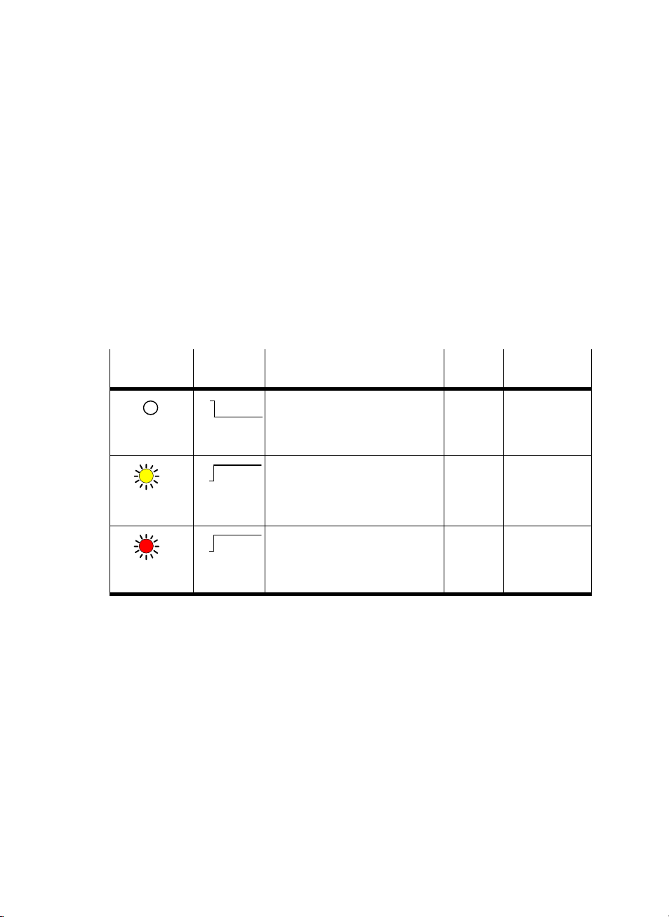
Status and error LEDs
The yellow LEDs indicate the status of the relevant output
(see also appropriate pneumatics manual).
The red LEDs indicate the faults of the MPA pneu
module depending on the parametrizing.
If the module fault Load voltage for valves missing or too
low", all LEDs will light up red.
LED
Sequence Status Fault
(yellow/red)
ON
OFF
LED is out
ON
OFF
LED lights up
yellow
ON
OFF
LED lights up
red
Faultless operation
Status of assigned channel logical 0
(output supplies 0−signal)
Faultless operation
Status of assigned channel logical 1
(output supplies 1−signal)
Fault in load voltage for valves
Load voltage for valves (V
missing or too low.
Tab.2/8: LEDs of the MPA pneumatic module
The fault indicated by red LEDs is transferred to the field bus
node by the MPA pneumatic module
otherwise).
VAL
matic
Fault
number
None
None
5 See section
)
treatment
2.5.1, Tab.2/7
(unless parametrized
Festo P.BE−CPX−EA−EN en 05602d
2−21

2. MPA pneumatic modules
2.5.3 Error treatment and parametrizing
The following diagram shows the error treatment for the MPA
pneumatic modules. Further registering and display of the
fault can be suppressed as desire
module parameter, represented in the diagram as a switch. A
description of the parameter can be found in section 2.4.
d with the appropriate
Fault message to
field bus node
01
Fault no. 5
Fault in load
voltage for
valves
Error LEDs
Monitoring
V
VAL
1 Module parameters
(switch position represented = default setting)
2 Module−specific faults
Fig.2/8:Principle of error treatment and parametrizing in
the MPA pneumatic module
1
2
2−22
Festo P.BE−CPX−EA−E N en 05602d

Overview and connecting technology I/O modules
Chapter 3
Type
CPX−AB−4−M12x2−5POL
CPX−AB−4−M12x2−5POL−R
CPX−AB−8−M8−3POL
CPX−AB−8−M8−4POL
CPX−AB−8−KL−4POL
CPX−AB−1−SUB−BU−25POL
CPX−AB−4−HARX2−4POL
CPX−AB−4−M12−8POL
3−1Festo P.BE−CPX−EA−EN en 05602d

3. Overview and connecting technology I/O modules
Contents
3. Overview and connecting technology I/O modules 3−1 . . . . . . . . . . . . . . . . . . .
3.1 Components of an I/O module 3−3 . . . .
3.2 Connections 3−4 . . . . . . . . . . . . .
3.2.1 Display and connecting elements 3−7 . .
3.2.2 Combinations of I/O modules and sub−bases 3−8 . . . . . . . . . . .
3.2.3 Connecting the cables and plugs to the sub−bases 3−10 . . . . . . . . . . . . .
3.3Fitting 3−20 . . . . . . . .
3.3.1 F
3.3.2 Fitting the
. . . . . . . . . . . . . . . . . . . . . . . . . . . . . . . . . . . . . . . . . . . . . . . .
itting the sub−bases 3−21 . . . . . . . . . . . . . . . . . . . . . . . . . . . . . . . . . . . . .
screening/shield plates 3−24 . . . . . . . . . . . . . . . . . . . . . . . . . .
. . . . . . . . . . . . . . . . . . . . . . . . . . . . . . . . . . . . . .
. . . . . . . . . . . . . . . . . . . . . . . . . . . . . . . .
. . . . . . . . . . . . . . . . . . . . . . . . .
. . . . . .
3−2
Festo P.BE−CPX−EA−E N en 05602d

3. Overview and connecting technology I/O modules
3.1 Components of an I/O module
All I/O modules consist of three parts:
The sub−base provides the electrical connections in the
form of different sockets or terminal strips.
1 Sub−base with
specific
connections
2 Electronic
module
3 Manifold
sub−base
The electronic
with the electronics and the LED display of the I/O mod
ule. The electronic module is fitted into the sub−b
is connected to this and to the manifold sub−base by
means of electric plug connectors.
The manifold sub−base as the lower part of the housing
provides
module and the valve terminal.
module contains the printed circuit board
ase and
the mechanical and electrical link between the
1
2
3
Fig.3/1: Components of an I/O module
Festo P.BE−CPX−EA−EN en 05602d
3−3

3. Overview and connecting technology I/O modules
3.2 Connections
Individual connection requirements can be fulfilled with
different sub−bases. These sub−bases provide the required
sockets or terminal strips for connect
actuators, irrespective of the I/O module used.
ing the sensors and
Sub−base
Type Description
CPX−AB−4−M12x2−5POL 4 M12 sockets, 5−pin
Protection class IP65/IP67
One functional earth connection per
socket
Screening/shielding possibility via
screening/shield plate
(see Accessories", appendixA.9)
CPX−AB−4−M12x2−5POL−R 4 M12 sockets with metal thread, 5−pin
Protection class IP65/IP67
One functional earth connection per
socket
Screening/shielding possibility via
metal thread
Enables M12 connectors and
SPEEDCON plug connectors to be
used.
CPX−AB−8−M8−3POL 8 M8 sockets, 3−pin
Protection class IP65/IP67
Tab.3/1: Connection designs part 1
3−4
Festo P.BE−CPX−EA−EN en 05602d

3. Overview and connecting technology I/O modules
Sub−base Type Description
CPX−AB−8−M8−4POL 8 M8 sockets, 4−pin
CPX−AB−8−KL−4POL 2 terminal strips, 16−pin (4 x 4−pin)
CPX−AB−1−SUB−BU−25POL 1 SUB−D socket, 25−pin
Protection class IP65/IP67
Protection class IP20
Protection class IP65/IP67 with cover
AK−8KL and screw connector set
VG−K−M9
All cores can be laid individually in
spring−clip terminals
Connections are in groups of 4, one
functional earth connection per
group
Protection class IP20
With plug type SD−SUB−D−ST25:
IP65/IP67 (see Accessories",
appendixA.9)
Tab.3/2: Connection designs part 2
Festo P.BE−CPX−EA−EN en 05602d
3−5

3. Overview and connecting technology I/O modules
Sub−base Type Description
CPX−AB−4−HARX2−4POL 4 HARAX connections, 4−pin
CPX−AB−4−M12−8POL 4 M12 sockets, 8−pin
Tab.3/3: Connection designs part 3
Protection class IP65/IP67 with the
plugs intended for this purpose
(see Accessories", appendixA.9)
Insulation−piercing connection
Protection class IP65/IP67
Intended for connecting cylinder−
valve combination type DNCV
Connections are arranged in groups,
one functional−earth connection per
group
Screening/shielding possibility via
screening/shield plate (see Acces
sories", appendixA.9)
3−6
Festo P.BE−CPX−EA−EN en 05602d

3. Overview and connecting technology I/O modules
3.2.1 Display and connecting elements
On all input and output modules the status LEDs and the
module identification can be seen through the transparent
cover of the sub−base.
All I/O modules have
elements irrespective of the sub−base used:
1 Rating plate
2 Module identification
(here 8DI for an input
module type
CPX−8DE)
5
3 Electrical connections
(example)
4 Inscription fields for
addresses
5 LEDs:
Inputs (green)
Outputs (yellow)
Faults (red)
4
Fig.3/2: Display and connecting elements
the following display and connecting
0
4
1
5
8
DI
2
6
3
7
1
2
3
Festo P.BE−CPX−EA−EN en 05602d
Use identity labels type IBS 6x10 for marking the addresses.
3−7

3. Overview and connecting technology I/O modules
3.2.2 Combinations of I/O modules and sub−bases
The following tables show the permitted combinations of I/O
modules with the sub−bases:
Sub−base type
CPX−AB−4−M12x2−5POL
(4 M12 sockets, 5−pin)
CPX−AB−4−M12x2−5POL−R
(4 M12 sockets with
metal thread, 5−pin)
CPX−AB−8−M8−3POL
(8 M8 sockets, 3−pin)
CPX−AB−8−M8−4POL
(8 M8 sockets, 4−pin)
CPX−AB−8−KL−4POL
(2 terminal strips, 16−pin)
CPX−AB−1−SUB−BU−25POL
(1 SUB−D socket, 25−pin)
CPX−AB−4−HARX2−4POL
(4 M12 sockets with in
sulation piercing, 4−pin)
CPX−AB−4−M12−8POL
(4 M12 sockets, 8−pin)
Digital input modules
CPX−4DE
(4 inputs)
CPX−8DE
CPX−8DE−D
CPX−8NDE
(8 inputs)
· ·
· ·
· ·
· · ·
· · ·
· ·
CPX−16DE
(16 inputs)
·
Can be combined
·
Cannot be combined
Tab.3/4: Permitted combinations of digital input modules with sub−bases
3−8
Festo P.BE−CPX−EA−EN en 05602d

3. Overview and connecting technology I/O modules
Sub−base type Digital output modules and multi I/O module
CPX−4DA
(4 outputs)
CPX−8DA
(8 outputs)
CPX−8DE/8DA
(8 inputs and outputs)
CPX−AB−4−M12x2−5POL
(4 M12 sockets, 5−pin)
CPX−AB−4−M12x2−5POL−R
(4 M12 sockets with
metal thread, 5−pin)
CPX−AB−8−M8−3POL
(8 M8 sockets, 3−pin)
CPX−AB−8−M8−4POL
(8 M8 sockets, 4−pin)
CPX−AB−8−KL−4POL
(2 terminal strips, 16−pin)
CPX−AB−1−SUB−BU−25POL
(1 SUB−D socket, 25−pin)
CPX−AB−4−HARX2−4POL
(4 M12 sockets with in
sulation piercing, 4−pin)
CPX−AB−4−M12−8POL
(4 M12 sockets, 8−pin)
Can be combined
·
Cannot be combined
· ·
· ·
· ·
· ·
· · ·
· · ·
· ·
·
Tab.3/5:Permitted combinations of digital output modules and multi I/O modules
with sub−bases
Festo P.BE−CPX−EA−EN en 05602d
3−9

3. Overview and connecting technology I/O modules
3.2.3 Connecting the cables and plugs to the sub−bases
Sensors and actuators must be connected to the CPX I/O
modules only at the sub−bases. In this way, e.g. when an elec
tronic module is rep
in the sub−base.
Warning
Sudden unexpected movement of the connected actuators
and uncontrolled movements of loose tubing can cause
injury to human beings or damage to prop
Before carrying out installation and maintenance work,
switch off the following:
the compressed air supply
the operating and load voltage supplies.
otection class of the I/O modules depends on the sub−
The pr
base used as well as on the plugs and protective caps used.
Instructions can be found
appendix A.6.
laced, the plugs and cables remain fitted
on the following pages and in the
erty.
3−10
Use plugs and cables from the Festo range for connecting
sensors and actuators (see appendix A.9
).
Festo P.BE−CPX−EA−EN en 05602d

3. Overview and connecting technology I/O modules
Sub−base CPX−AB−4−M12x2−5POL(−R)
Please note
In order that the completely fitted modules with sub−base
CPX−AB−4−M12x2−5POL(−R) comply with protection class
IP65/IP67:
· Use plugs and cables from the Festo range for connect
ing the sensors and actuators (see appendix A.9).
· Tighten the union nuts of the plugs at first by hand.
· Seal unused sockets with protective caps type ISK−M12
(Accessories).
The sub−base with metal thread (CPX−AB−4−M12x2−5POL−R)
enables fast locking systems to be
Phoenix Contact.
· When using fast locking systems follow the manufac
turer’s instructions in order to comply with protection
class IP65/IP67.
used, e.g. SPEEDCON from
Festo P.BE−CPX−EA−EN en 05602d
Screening/shield
On
plugs without metal housing:
· Connect the cable screening/shield to pin 5
(functional earth FE).
On plugs with metal housing:
· Use the sub−base with metal thread
(type CPX−AB−4−M12x2−5POL−R). The metal thread of
this sub−base is connected internally to pin 5 (FE).
or
· Connect the cable screening via the plug housing and
the screening plate with FE.
3−11

3. Overview and connecting technology I/O modules
Screening plate type CPX−AB−S−4−12
Sub−base CPX−AB−4−M12x2−5POL (without metal thread) can
be combined with a screening/shield plate. Depending on
what you h
ave ordered, this may already be fitted on the
sub−base.
Instructions on subsequent fitting of the screening/shield
plate can be found in section 3
The electromagnetic compatibility can be improved with
screening/shield plates, e.g. in environments heavily sub
jected to interference o
pose the screening/shield plates must be earthed at the flat
contact intended for this purpose as per DI N 46244 B2
(2.8 x 1 mm).
· Connect the earth cable of the screening/shield plate
with low impedance to the functional earth connection
(FE) as per Fig.3/3.
Screening/shield pla
connected together by spring clips and must not be
connected individually to FE.
.3.2.
r for analogue signals. For this pur
,8−1
tes lying next to each other are
3−12
If the intended pl
ugs are used (see Accessories, appendix
A.9), the plug housing will be connected to functional earth
via the screening/shield plate by means of the s
pring con
tacts.
· Before fitting the plugs screw the spring contacts as far as
possible onto the thread of the plug.
Festo P.BE−CPX−EA−EN en 05602d

3. Overview and connecting technology I/O modules
1 Plug
2 Spring contact
3 Screening/shield
plate
4 Functional earth
connection (FE)
with blade
connector as per
DIN46245
B2,8−1
Fig.3/3: Connecting the screening/shield plate
Please note
In order to comply with protection class IP65/IP67:
· Do not use the spring contacts if you have sealed
unused sockets with protective caps.
1
2
3
4
Festo P.BE−CPX−EA−EN en 05602d
3−13

3. Overview and connecting technology I/O modules
Sub−bases CPX−AB−8−M8−3POL and −4POL
Please note
In order that the completely fitted modules with sub−bases
CPX−AB−8−M8−3POL and −4POL comply with protection
class IP65/IP67:
· use plugs and cables from the Festo range for connect
ing the sensors and actuators (see appendix A.9).
· Tighten the union nuts of the plugs at first by hand.
· Seal unused sockets with protective caps type ISK−M8
(Accessories).
Sub−base CPX−AB−8−KL−4POL
The completely fitted sub−base CPX−AB−8−KL−4POL complies
with protection class IP20.
3−14
Specifications of the cable terminals
Cable cross−sectional area: 0.08 ...
1.5 mm
2
Max. current: 1.5 A
Insulation removed: 5 ... 6 mm
Permitted copper conductors
Single wire, multi−wire, fine wire, also with tinh−plated
ndividual cores
i
Fine wire strands compressed
Fine wire with core end sleeves
(sealed against gas, crimped on)
*)
Fine wire with pin cable socket
(sealed against gas, crimped on
*)
If necessary, use next smaller cross−sectional area.
*)
Festo P.BE−CPX−EA−EN en 05602d

3. Overview and connecting technology I/O modules
1 Screwdriver, blade
2.5 x 0.4 mm
1
2 Unlocking opening
(inside)
3
3 Cable
4 Terminal opening for
inserting the
conductors (outside)
5 Terminal strips
45
Fig.3/4: Fitting and removing the cables
Fitting and removing the cables
Please note
· To ensure reliable contact, connect only one conductor
per spring terminal.
· Insert only cables into the terminal opening. The ter
minal will be damaged if a screwdriver is inserted into
the opening.
1
2
3
4
5
2
Festo P.BE−CPX−EA−EN en 05602d
When connect
1. Press the screwdriver with a light rotary movement to
wards the centre of the unlocking opening (see Fig.3/4).
The
2. When the terminal is unlocked you can insert or pull out
the ends of the cable through the opening.
3. Remove the screwdriver from the unlocking opening.
The cable will then be securely locked.
ing and disconnecting the cables:
cable terminal will then be unlocked.
3−15

3. Overview and connecting technology I/O modules
You will then comply with protection class IP65/IP67
In order that sub−base CPX−AB−8−KL−4POL complies with
protection class IP65/IP67, use cover type AK−8KL
screw connector set type VG−K−M9 from Festo. Note the
relevant fitting instructions.
1 Cover AK−8KL
2 Screw connector
set VG−K−M9
1
and the
2
Fig.3/5: Cover and screw connector set for sub−base CPX−AB−8−KL−4POL
(for complying with protection class IP65/67)
Sub−base CPX−AB−1−SUB−BU−25POL
The completely fitted sub−base CPX−AB−1−SUB−BU−25POL
complies with protection class IP20.
In order that sub−base CPX−AB−1−SUB−BU−25POL complies
with protection class I
SD−SUB−D−ST25 from Festo.
When fitting the plug onto the sub−base, observe the
maximum tightening torque of 0.5 Nm.
3−16
P65/IP67, use plug type
Festo P.BE−CPX−EA−EN en 05602d

3. Overview and connecting technology I/O modules
Sub−base CPX−AB−4−HARX2−4POL
Please note
In order that completely fitted modules with sub−base
CPX−AB−4−HARX2−4POL comply with protection class
IP65/IP67:
· Use plugs type SEA−GS−HAR−4POL from the Festo range
(consisting of union nut, strain relief and splicing ring)
for connecting sensors and actuators.
· Tighten the union nuts of the plugs at first by hand.
· Seal the unused connecting sockets with protective
caps from Harting (see Accessories, appendixA.9).
Specifications of the cables for the sub−base
CPX−AB−4−HAR
Cable cross−sectional area: 0.25 ... 0.5 mm
X2−4POL
2
Festo P.BE−CPX−EA−EN en 05602d
Strand cross−section: up to 0.1 mm
Insulation material:PVC/PUR/PE
Insulation thickness: max. 1.6 mm
Core diameter: 1.2 ... 1.6 mm
Cable outer diameter: 4.0 ... 5.1 mm
3−17

3. Overview and connecting technology I/O modules
Fitting
1 Cut the cable to
length and remove
the coating. Push the
union nut and the
seal insert onto the
end of the cable.
2 Insert the ends of the
core into the ap
propriate slots of the
splicing ring.
4
3 Place the seal and
the splicing ring to
gether and cut off the
projecting core ends
flush with the splicing
ring.
1
3
2
1
2
3
4 Insert the pre−fitted
splicing seal element
into the contact sup
port in the sub−base.
Screw in the union
nut as far as possible.
Fig.3/6: Connecting the cables to sub−base CPX−AB
Dismantling
· Loosen the screw connector and remove the cores by
pulling them out of the contacts.
The cores can be connected up to 10 times if the contact
ends are
used). Cut off the used cable ends and repeat steps 2 to 4.
3−18
cut away each time (if the same core diameter is
4
Festo P.BE−CPX−EA−EN en 05602d

3. Overview and connecting technology I/O modules
Sub−base CPX−AB−4−M12−8POL
Please note
In order that completely fitted modules with sub−base
CPX−AB−4−M12−8POL comply with protection class
IP65/IP67:
· Use cable type KM12−8GD8GS−2−PU from Festo for
connecting the cylinder−valve combination type DNCV or
other sensors and actuators (see appendix
· Tighten the union nuts of the plugs at first by hand.
· Seal unused sockets with protective caps type ISK−M12
(Accessories).
Screening plate type CPX−AB−S−4−12
Sub−base CPX−AB−4−M12−8POL can be combined with a
screening plate. Connecting plate must be ordered separately
as an accessory.
A.9).
Festo P.BE−CPX−EA−EN en 05602d
Instructions on subsequent fitting of the screening/shield
plate can be found
in section 3.3.2.
Instructions on using the screening plates can be found with
sub−base CPX−AB−4−M12x2−5POL.
3−19

3. Overview and connecting technology I/O modules
3.3 Fitting
Warning
Sudden unexpected movement of the connected actuators
and uncontrolled movements of loose tubing can cause
injury to human beings or damage to prop
Before carrying out installation and maintenance work,
switch off the following:
the compressed air supply
the operating and load voltage supplies.
Caution
Modules may be damaged if they are not handled
correctly.
· Do not touch the electrical contacts of the modules.
· Observe the regulations for handling electrostatically
sensitive components.
· Discharge yourself electrostatically before fitting or re
moving components in order to protect the components
against discharges of static electrici
erty.
ty.
3−20
Before the CPX terminal can be extended or converted, it
must first be unscrewed and dismantled. Instructions on this
can be found in
the CPX system manual.
The CPX terminal does not need to be dismantled when sub−
bases or electronic modules are fitted or removed. This also
to the plugs and cables on the sub−base.
applies
Festo P.BE−CPX−EA−EN en 05602d

3. Overview and connecting technology I/O modules
3.3.1 Fitting the sub−bases
Please note
Handle all modules and components of the CPX terminal
with great care. Please note especially the following:
· Screws must be fitted accurately (otherwise threads will
be damaged).
Screws must be fastened at first only by hand. Place the
screw
s so that the self−cutting threads are used.
· The specified torques must be observed.
· Screw connections must be fitted free of offset and
mechanical tension.
· Check the seals for damage (I P65/IP67).
· Connecting surfaces must be clean (to ensure sealing
effect, avoid leakage and contact faults).
The screw connection between the sub−base and the mani
fol
d sub−base is designed to withstand at least 10 fitting/
removal cycles under observance of the instructions.
Observe also the installation instructions
modules and components ordered at a later stage.
supplied with
Festo P.BE−CPX−EA−EN en 05602d
CPX terminals are supplied from the factory completely fitted.
It may be necessary
to fit or remove the sub−bases for the
following reasons:
for replacing the connections
to simplify fitting the sensor plugs or cables.
It may be necessary
to fit or remove the electronic modules
for the following reasons:
for changing the function of the I/O module
(e.g. CPX−8DE instead of CPX−4DE)
for replacing defective electronic modules.
3−21

3. Overview and connecting technology I/O modules
Dismantling Dismantle the sub−base as follows (see Fig.3/7):
1. Loosen the 4 screws in the relevant sub−base with a Torx
screwdriver size T10.
1 Sub−base
2 Screws
3 Electrical plug
connector
4 Electronic
module
5 Contact rails
6 Manifold
sub−base
2. Pull the sub−base carefully
the electrical plug connection of the electronic module.
Only in cases where the electronic module is to be removed:
· Pull the electronic module carefully and without tilting
away from the contact rails of the manifold sub−base.
and without tilting away from
1
3
2
4
5
6
Fig.3/7: Fitting/removing the I/O module
3−22
Festo P.BE−CPX−EA−EN en 05602d

3. Overview and connecting technology I/O modules
Fitting Fit the modules as follows (see Fig.3/7):
Please note
· Please observe the instructions on combining
I/Omodules and sub−bases in section 3.2.2.
· Please observe the instructions on combining and
arranging modules on the CPX terminal in the CPX
system manual.
Only in cases where the electronic
module has been
removed:
· Place the electronic module in the manifold sub−base.
Make sure that the grooves with the contact terminals on
the bottom of the electronic module lie abov
e the contact
rails. Then push the electronic module carefully and with
out tilting as far as possible into the manifold sub−base.
Fitting the sub−base:
1. Align the
sub−base over the manifold sub−base with the
electronic module. Make sure that the plug connectors of
the sub−base are aligned exactly with the connecto
rs of
the electronic module. Then push the sub−base carefully
and without tilting onto the manifold sub−base.
2. Tighten the screws at first only by ha
nd. Place the screws
so that the self−cutting threads can be used.
Tighten the screws with a Torx screwdriver size T10 with
torque 0.9 ... 1.1 N
m.
Festo P.BE−CPX−EA−EN en 05602d
3−23

3. Overview and connecting technology I/O modules
3.3.2 Fitting the screening/shield plates
A screening plate type CPX−AB−S−4−12 can be fitted on sub−
bases CPX−AB−4−M12x5−5POL and CPX−AB−4−M12−8POL.
The sub−base must be removed before the termin
or dismantled.
Fitting Fit the screening plate as follows (see Fig.3/8):
1. Dismantle the sub−base (see section 3.3.1).
al is fitted
2. Snap the spring clips of th
e screening/shield plate from
above into the appropriate recesses on the dismantled
sub−base.
3. Fit the sub−base.
Instructions on earthing the screening/shiel
d plate can be
found in section 3.2.3.
Dismantling The screening/shield plate must be removed in the opposite
sequence to the fitting procedure.
3−24
Festo P.BE−CPX−EA−EN en 05602d

3. Overview and connecting technology I/O modules
1 Spring contact
2 Screening/shield
plate
3 Spring clip
4 Sub−base type
CPX−AB−4−
M12x2−5POL or
CPX−AB−4−
M12−8POL
5 CPX terminal
1
2
3
4
5
Fig.3/8:Fitting screening/shield plate type CPX−AB−S−4−12
Festo P.BE−CPX−EA−EN en 05602d
3−25

3. Overview and connecting technology I/O modules
3−26
Festo P.BE−CPX−EA−EN en 05602d

Input modules
Chapter 4
Type
CPX−4DE
CPX−8DE
CPX−8DE−D
CPX−16DE
CPX−8NDE
4−1Festo P.BE−CPX−EA−EN en 05602d

4. Input modules
Contents
4. Input modules 4−1 . . . . . . . . . . . . . . . . . . . . . . . . . . . . . . . . . . . . . . . . . . . . . . . . .
4.1 Function of the input modules 4−3 . . . . . . . . . . . . . . . . . . . . . . . . . . . . . . . . . . .
4.2 Fitting 4−4 . . . . . . . . . . . . . . . . . . . . . . . . . . . . . . . . . . . . . . . . . . . . .
4.3 Installation4−5 . . . . . . . . . . . . . . . . . . . . . . . . . . . . . . . . .
4.3.1 Input module CPX−4DE4−6 . . . . . . . . . . . . . . . . . . . . . . .
4.3.2 Input module CPX−8DE4−11 . . . . . . . . . . . . . . . . . . . . . . . . . . . . . . .
4.3.3 Input module CPX−8DE−D with channel diagnosis 4−16 . . . . . . . . . . . . . .
4.3.4 Input module CPX−16DE4−21 . . . . . .
4.3.5 Input module CPX−8NDE4−24 . . . . . . . . . . . . .
4.4 Instructions on commissioning 4−29 . . . . . . . . . . . . . . . . . .
4.4.1 Parameters of the input modules type CPX−4DE, −8DE,
−8DE−D, −16DE and −8NDE4−29 . . . .
4.5 Diagnosis 4−33 . . . . . . . . . . . . . . . . . . .
4.5.1 Fault messages of the input modules 4−33 . . . .
4.5.2 LED display 4−35 . . . . . . . . . . . . . . . . . . . . . . . . .
4.5.3Fault treatment and parametrizing 4−38 . . . . . . . . . . . . . . . . . .
. . . . . . . . . . . . . . . . . . . . . . . . . . . .
. . . . . . . . . . . . . . . . . . . . . . . . . . . . .
. . . . . . . . . . . . . . . . . . . . . . . . . . . . . . . . . .
. . . . . . . . . . . . . . . . . . .
. . . . . . . . . . . . . . . . . . . . .
. . . . . . . . . . . . . . . . . .
. . . . . . . . . . . . . . . . . . .
. . . . . . . . . . . . . . . . . . .
. . . . . . . . . . .
. . . . . . . . . . . .
. . . .
. . . . . . . .
. .
4−2
Festo P.BE−CPX−EA−E N en 05602d

4. Input modules
4.1 Function of the input modules
Input modules provide digital inputs in the valve terminal for
connecting sensors and for enabling e.g. cylinder positions to
be scanned. A
types:
distinction is made between the following
Type
CPX−4DE Provides 4 digital inputs
CPX−8DE Provides 8 digital inputs
CPX−8DE−D Provides 8 digital inputs with
Description
(as per IEC 1131 type 2, 24V,
positive logic PNP)
(as per IEC 1131 type 2, 24V,
positive logic PNP)
channel diagnosis
(as per IEC 1131 type 2, 24V,
positive loigic PNP)
Tab.4/1: Overview of input modules (part 1)
Festo P.BE−CPX−EA−EN en 05602d
4−3

4. Input modules
Type Description
4.2 Fitting
CPX−16DE Provides 16 digital inputs
(as per IEC 1131 type 2, 24V,
positive logic PNP)
CPX−8NDE Provides 8 digital inputs
(as per IEC 1131 type 2, 24V,
negative logic NPN)
Tab.4/2: Overview of input modules (part 2)
See chapter 3.3.
4−4
Festo P.BE−CPX−EA−EN en 05602d

4. Input modules
4.3 Installation
Warning
Sudden unexpected movement of the connected actuators
and uncontrolled movements of loose tubing can cause
injury to human beings or damage to prop
erty.
Before carrying out installation and maintenance work,
switch off the following:
the compressed air supply
the operating and load voltage supplies.
e following sections you will find the pin assignments of
In th
the input modules for the different sub−bases.
Festo P.BE−CPX−EA−EN en 05602d
Instructions on connecting the cables and plugs to th
e sub−
bases can be found in section 3.2.3.
Power supply
The 24 V sensor supply for the inputs as well as the power
supply for the electronics of the input modules is provided
via the operating voltag
(V
EL/SEN
).
e supply for the electronics/sensors
4−5

4. Input modules
4.3.1 Input module CPX−4DE
Pin assignment CPX−4DE with sub−base
CPX−AB−4−M12x2−5POL(−R)
I−module type CPX−4DE with sub−base CPX−AB−4−M12x2−5POL(−R)
Sub−base Pin assignment X1, X2 LED Pin assignment X3, X4 LED
0
1
4
DI
2
3
3
2
X1
1: 24 V
2: Ix+1
3: 0 V
4: Ix
5: FE
SEN
SEN
1)
5
1
1
2
3
Socket X2:
1: 24 V
SEN
2: n.c.
3: 0 V
SEN
4: Ix+1
1)
5: FE
X2
1
5
4
3
1
0
2
X3
1
X4
1
5
1
4
Socket X1:
4
4
2
5
1
3
Socket X3:
1: 24 V
SEN
2: Ix+3
3: 0 V
SEN
4: Ix+2
1)
5: FE
Socket X4:
1: 24 V
SEN
2: n.c.
3: 0 V
SEN
4: Ix+3
1)
5: FE
Ix=Input x
FE = Functional earth
n.c. =not connected
1 Connected internally
1)
With CPX−AB−4−M12x2−5POL−R the metal thread is connected to FE
Tab.4/3: Pin assignment of I−module type CPX−4DE with sub−base
CPX−AB−4−M12x2−5POL(−R)
CPX−AB−4−M12x2−5POL−R The metal thread (...−R") of this sub−base is connected
internally wi
th pin 5 (Functional earth FE).
Recommendation for the 4−input module:
Use the Festo DUO cable in order to connect two sensors to
sockets X1 and X3
with one plug at low cost.
3
2
3
4−6
Festo P.BE−CPX−EA−EN en 05602d

4. Input modules
Pin assignment CPX−4DE with sub−base
CPX−AB−8−M8−3POL
Please note
Sockets X1 to X8 on the sub−base are marked accordingly.
The numbering of the sockets does not correspond to the
input addresses.
I−mod
ule type CPX−4DE with sub−base CPX−AB−8−M8−3POL
Sub−base Pin assignment X1 to X4 LED Pin assignment X5 to X8 LED
X1
0
1
4
DI
2
3
X1
X2
X5
X6
4 1
3
X2
4 1
3
Socket X1:
1: 24 V
SEN
3: 0 V
SEN
4: Ix
Socket X2:
1: 24 V
SEN
3: 0 V
SEN
4: Ix+1
0
1
1
X3
X4
X7
X8
X3
4 1
3
X4
4 1
3
Socket X3:
1: 24 V
SEN
3: 0 V
SEN
4: Ix+1
Socket X4:
1: 24 V
SEN
3: 0 V
SEN
4: n.c.
1
4 1
3
4 1
3
1
4 1
3
4 1
3
X5
X6
X7
X8
Socket X5:
1: 24 V
SEN
3: 0 V
SEN
4: Ix+2
Socket X6:
1: 24 V
SEN
3: 0 V
SEN
4: Ix+3
Socket X7:
1: 24 V
SEN
3: 0 V
SEN
4: Ix+3
Socket X8:
1: 24 V
SEN
3: 0 V
SEN
4: n.c.
2
3
3
Ix=Input x
n.c. =not connected
1 Connected internally
Tab.4/4: Pin assignment of I−module type CPX−4DE with sub−base CPX−AB−8−M8−3POL
Festo P.BE−CPX−EA−EN en 05602d
4−7

4. Input modules
Pin assignment CPX−4DE with sub−base
CPX−AB−8−KL−4POL
Please note
Pins X1 to X8 on the sub−base are marked accordingly.
The numbering of the pins does not correspond to the
input addresses.
I−modul
e type CPX−4DE with sub−base CPX−AB−8−KL−4POL
Sub−base Pin assignment X1 to X4 LED Pin assignment X5 to X8 LED
.0
X1
0
1
4
DI
2
3
.0
X1
X2
X3
X4
X5
.1
.2
.3
.0
.1
.2
.3
.0
.1
.2
.3
.0
.1
.2
.3
X2
X6
X7
X3
X8
X4
.1
.2
.3
.0
.1
.2
1
.3
.0
.1
.2
.3
.0
.1
.2
.3
X1.0: 24 V
X1.1: 0 V
X1.2: Ix
X1.3: FE
X2.0: 24 V
X2.1: 0 V
X2.2: Ix+1
X2.3: FE
X3.0: 24 V
X3.1: 0 V
X3.2: Ix+1
X3.3: FE
X4.0: 24 V
X4.1: 0 V
X4.2: n.c.
X4.3: FE
SEN
SEN
SEN
SEN
SEN
0
SEN
1
SEN
1
SEN
1
.0
.1
.2
.3
.0
.1
.2
.3
.0
.1
.2
.3
.0
.1
.2
.3
X5.0: 24 V
X5
X5.1: 0 V
X5.2: Ix+2
X5.3: FE
X6.0: 24 V
X6.1: 0 V
X6
X6.2: Ix+3
X6.3: FE
X7.0: 24 V
X7.1: 0 V
X7
X7.2: Ix+3
X7.3: FE
X8.0: 24 V
X8.1: 0 V
X8.2: n.c.
X8
X8.3: FE
SEN
SEN
SEN
SEN
SEN
SEN
SEN
SEN
Ix=Input x
FE = Functional earth
n.c. =not connected
1 Connected internally
Tab.4/5:Pin assignment of I−module type CPX−4DE with sub−base CPX−AB−8−KL−4POL
2
3
3
4−8
Festo P.BE−CPX−EA−EN en 05602d
 Loading...