

Page 1
Motor controller
SFC−DC
Manual
Function block S7
for motor controller
type SFC−DC
Manual
700 332
en 0604NH
Page 2

Page 3

Contents and general instructions
Original de. . . . . . . . . . . . . . . . . . . . . . . . . . . . . . . . . . . . . . .
Edition en 0604NH. . . . . . . . . .
. . . . . . . . . . . . . . . . . . . . . . .
Designation P.BE−SFC−DC−PB−S7−EN. . . . . . . . . . . . . . . . . . .
Order no. 700 332. . . . .
. . . . . . . . . . . . . . . . . . . . . . . . . . . .
© (Festo AG&Co. KG, D73726 Esslingen, 2006)
Internet: http://www.festo.com
E−Mail: service_international@festo.com
The reproduction, distribution and utilization of this docu
ment as well as the communicaton of its
contents to others
without express authorization is prohibited. Offenders will
be held liable for the payment of damages. All rights reser
ved in the event of the grant of a patent, utility module or
design.
Festo P.BE−SFC−DC−PB−S7−EN en 0604NH
I
Page 4

Contents and general instructions
PROFIBUS
SIMATIC
®
®
is a registered trade name of PROFIBUS International (P.I.)
is a registered trade name of Siemens AG
II
Festo P.BE−SFC−DC−PB−S7−EN en 0604NH
Page 5

Contents and general instructions
Contents
Designated use VII . . . . . . . . . . . . . . . . . . . . . . . . . . . . . . . . . . . . . . . . . . . . . . . . . . . . . . . .
Basic principles of programmed software VIII . . . . . . . . . . . . . . . . . . . . . . . . . . . . . . . . . . .
Safety instructions IX .
Target group X . . . . . . . . . . . . . . . . . . . . . . . . . . . . . . . . . . . . . . . . . . . . . . .
Service X . . . . . . . . . . . . . . . . . . . . . . . . . . . . . . . . . . . . . .
Important user instructions XI . . . . . . . . . . . . . . . . . . . . . . .
Manuals on motor controller type SFC−DC XIII . . . . . . . . . . . . . . . . . . . . .
Information on the versions XV . . . . . . . . . . . . . . . . . . . . . . . . . . . . . . . . .
Product−specific terms and abbreviations XVI . . . . . . . . . . . . . . . . . . . . . . . . . . . . . . . . .
PROFIBUS−specific terms and abbreviations XVIII . . . . . . . . . . . . . . . . . . . . . . . . . . . . . . . . .
. . . . . . . . . . . . . . . . . . . . . . . . . . . . . . . . . . . . . . . . . . . . . . . . . . . .
. . . . . . . . . . .
. . . . . . . . . . . . . . . . . . . . . . . . .
. . . . . . . . . . . . . . . . . . . . . . .
. . . . . . . . . . . . . .
. . . . . . . . . . . . .
. .
1. Overview 1−1 . . . . . . . . . . .
1.1 General description 1−3 . . . . .
1.2 The blocks at a glance 1−4 . . . . . .
1.3 Festo Profile for Handling and Positioning (FHPP) 1−5 . . . . . .
2. Installation and overview of the projects 2−1 . . . . . . . . . . . . . . . . . . . . . . . . . .
2.1 Configuration 2−3 . . . . . . . . . . . . . . . . . . . . . . . . . . . . . . . . . . . . . . . . . . . . . . . . . .
2.1.1 Install device
2.1.2 I/O configuration 2−4 . . . . . . . . . . . . . . . . . . . . . . . . . . . .
2.1.3 Configuration with STEP 7 2−5 . . . . . . . . . . . . . . . . . . . . . . . . . . . . . . . . .
2.2 Dearchivating
2.3 Overview of project 2−12 . . . . . . . . . . . .
2.3.1 Folder _CTRL" control functions 2−12 . . . . . . . . . . . .
2.3.2 Folder _PRM_FPC" parametrizing via FPC 2−13 . . . . . . . . . . . . . . . . . .
2.3.3 Folder PRM_DPV1_SFB" parametrizing via DPV1 2−14 . . . . . . .
2.3.4 Folder PRM_DPV1_SFC" parametrizing via DPV1 2−15 . . . . . . . . . . . .
2.3.5 Folder PRM_UP−DOWNLOAD" transmitting several
the example project 2−10 . . . . . . . . . . . . . . . . . . . . . . . . . . . . . . . . .
parameters 2−16 . . . . . . . . . . . . . . . . . . . . .
. . . . . . . . . . . . . . . . . . . . . . . . . . . . . . . . . . . . . . . . . . .
. . . . . . . . . . . . . . . . . . . . . . . . . . . . . . . . . . . . . . . .
. . . . . . . . . . . . . . . . . . . . . . . . . . . . . . . . . . . . .
. . . . . . . . . . . . . . .
master file (GSD file) and icon files 2−3 . . . . . . . . . . . . . .
. . . . . . . . . . . .
. . . . . . . . . . . . . . . . . . . . . . . . . . . . . . . . .
. . . . . . . . . . . . . .
. . . . .
. . . . . . . . . . . . . . . . . . . . . . . .
Festo P.BE−SFC−DC−PB−S7−EN en 0604NH
III
Page 6

Contents and general instructions
3. Control block 3−1 . . . . . . . . . . . . . . . . . . . . . . . . . . . . . . . . . . . . . . . . . . . . . . . . . .
3.1 Function block SFC_DC_CTRL" 3−3 . . . . . . . . . . . . . . . . . . . . . . . . . . . . . . . . . . .
3.1.1 Description of method of operation 3−4 . . . . . .
3.1.2 Input parameters 3−6 . . . . . . . . . . . . . . . . . . . . . . . . . . . . . .
. . . . . . . . . . . . . . . . . . .
. . . . . . . . . .
3.1.3 Output parameters 3−8 . . . . . . . . . . . . . . . . . . . . . . . . . . . . . . . . . . . . . .
3.1.4 Fault information 3−10 . . . . . . . . . . . . . . . . . . . . . . . . . . . . . . . . . . . . . . . .
4. Parametrizing blocks 4−1 . . . . . . .
4.1 Overview of parametrizing blocks 4−3 . . . . . . . . . .
4.1.1 Control and parametrizing methods 4−4 . . . . . . . . . . . . . . . . . . . . . . .
. . . . . . . . . . . . . . . . . . . . . . . . . . . . . . . . . . . .
. . . . . . . . . . . . . . . . . . . . . . . .
. .
4.1.2 Method of operation of the modules 4−4 . . . . . . . . . . . . . . . . . . . . . . . .
4.1.3 Converting the measuring units 4−5 . . . . . . . . . . . . . .
4.2 Block PRM_FPC 4−6 . . . . . . . . . . . . . . . . . . . . . . . . . . . . . . . . . . .
4.2.1 Input parameters 4−7 . . . . . . . . . . . . . . . . . . . . . . . . . . . . . . . . . . .
. . . . . . . . . . . . . .
. . . . . . . . . . . . .
. . . . .
4.2.2 Output parameter 4−7 . . . . . . . . . . . . . . . . . . . . . . . . . . . . . . . . . . . . . . .
4.3 Blocks PRM_DPV1_SFB / PRM_DPV1_SFC 4−8 .
4.3.1 Input parameters 4−9 . . . . . . . . . . . . . . . . . . . . . . .
4.3.2 Output parameters 4−9 . . . . . . . . . . . . . . . . . . . . . . . . . . . . . . . .
4.4 Block PRM_DB−FILE 4−10 . . . . . . . . . . . . . . . . . . . . . . . . . . . . . . . . . . . . . . . . . .
. . . . . . . . . . . . . . . . . . . . . . . . .
. . . . . . . . . . . . . . . . .
. . . . . .
. . .
4.4.1 Description of method of operation 4−11 . . . . . . . . . . . . . . . . . . . . . . . . .
4.4.2 Input parameters 4−13 . . . . . . . . . . . . . . . .
4.4.3 Output parameters 4−14 . . . . . . . . . . . . . . . . . . . . . . . .
4.4.4 Implementation 4−15 . . . . . . . . . . . . . . . . . . . . . . . . . . . . . . . . . . . .
4.4.5 Restriction 4−15 . . . . . . . . . . . . . . . . . . . . . . . . . . . . . . . . . . . . . . . . . . . .
. . . . . . . . . . . . . . . . . . . . . . . .
. . . . . . . . . . . . . .
. . . . .
.
4.5 Fault information 4−16 . . . . . . . . . . . . . . . . . . . . . . . . . . . . . . . . . . . . . . . . . . . . . . .
5. Examples 5−1
5.1 Examples with the control block 5−3 . . . . . . . . . . . . . . . . . . . . . . . . . . . . . . . . . . .
5.1.1 Enable controller 5−4 . . . . . .
5.1.2 Selecting the operating mode 5−5 . . . . . . . . . . . .
. . . . . . . . . . . . . . . . . . . . . . . . . . . . . . . . . .
. . . . . . . . . . . . . . . . . .
5.1.3 Starting a positioning task in direct mode 5−5 . . . . . . . . . . . . . . . . . . . .
5.1.4 Starting a positioning task in Record
5.2 Downloading a parameter list 5−8 . . . . . . . . . . . . . . . . . . . . . . . . . . . . . . .
Select mode 5−7 . . . . . . . . . . . . .
. . . . . .
. . . . . . . . . . . . . . . . . . . . . . . . . . . . . . . . . . . . . . . . . . . . . . . . . . . . .
IV
Festo P.BE−SFC−DC−PB−S7−EN en 0604NH
Page 7

Contents and general instructions
A. Technical appendix A−1 . . . . . . . . . . . . . . . . . . . . . . . . . . . . . . . . . . . . . . . . . . . . .
A.1 Festo profile for handling
A.1.1 Supported operating modes A−3 . . . . . . . . . . . . . . . . . . . . . . .
A.2 Drive functions A−5 . . . . . . . . . . . . . . . . . . . . . . . . . . . . . . . . . . . . . . . . .
and positioning (FHPP) A−3 . . . . . . . . . . . . . . . . . . . . .
. . . . . . . .
. . . . . . . .
A.2.1 Reference system for electric drives A−5 . . . . . . . . . . . . . . . . . . . . . . . .
A.2.2 Reference travel A−7 . . . . . . . . . . .
A.2.3 Jogging A−9 . . . . . . . . . . . . . . . . . . . .
A.2.4 Teaching via field bus A−11 . . . . . . . . . . . . . . . . . .
. . . . . . . . . . . . . . . . . . . . . . . . . . . . . .
. . . . . . . . . . . . . . . . . . . . . . . . . . . .
. . . . . . . . . . . . . . . . . .
A.2.5 Carry out record (Record Select) A−13 . . . . . . . . . . . . . . . . . . . . . . . . . . .
A.2.6 Specifying
A.2.7 Standstill monitoring A−21 . . . . . . . . . . . . . . . . . . . . . . . . .
A.3 Fault messages A−23 . . . . . . . . . . . . . . . . . . . . . . . . . . . . . . . . . . . . .
A.4 Diagnostic memory A−25 . . . . . . . . . . . . . . . . . . . . . . . . . . . . . . . . . . . .
a position directly (Direct mode) A−18 . . . . . . . . . . . . . . . . . .
. . . . . . . . . . . .
. . . . . . . . . . . .
. . . . . . . . .
A.5 Diagnosis via PROFIBUS−DP A−27 . . . . . . . . . . . . . . . . . . . . . . . . . . . . . . . . . . . . . .
A.5.1 Structure
B. Supplementary information B−1 . . . . . . . . . . . . . .
B.1 Parameters of the SFC−DC B−3 . . . . . . . . . . . . . . . . . . . . . . .
of the DP diagnosis A−27 . . . . . . . . . . . . . . . . . . . . . . . . . . . . . .
. . . . . . . . . . . . . . . . . . . . . . . .
. . . . . . . . . . . . . . . . .
B.1.1 General parameter structure B−3 . . . . . . . . . . . . . . . . . . . . . . . . . . . . . .
B.1.2 Overview of parameters B−4 . . . . . . . . . . . . . . . . . . . . . . . . . . . . . . . . . .
C. Index C−1 . . . . . . . . . . . . .
. . . . . . . . . . . . . . . . . . . . . . . . . . . . . . . . . . . . . . . . . . . .
Festo P.BE−SFC−DC−PB−S7−EN en 0604NH
V
Page 8

Contents and general instructions
VI
Festo P.BE−SFC−DC−PB−S7−EN en 0604NH
Page 9

Contents and general instructions
Designated use
The function blocks (FB) described serve for controlling and
parametrizing motor controllers type SFC−DC−...−PB via PROFI
BUS−DP in a SIMATIC−S7 controller with integrated DP master
module (e.g. CPU315−2DP).
With the blocks the many functions of the motor controller
can be comfortably incorporated in the program.
The blocks can be parametrized and are capable of
many
instances. They are linked into the user program for each
motor controller (each axis) from where they can be accessed
cyclically with a separate instance data block or multi−in
stance block. Simultaneous use of other function blocks for
controlling the same controller is not permitted.
The motor controller (Single Field Controller, single
axis field
controller) type SFC−DC−... serves as a position controller and
position servo for the electric mini slide type SLTE−... with
control via the PROFIBUS field bus.
It is absolutely necessary to observe the Safety instructions"
as well as the designated use of the relevant components and
modules listed in the manual for the
SFC−DC. Please observe
also the safety instructions in the operating instructions for
the components used.
If additional commercially−available components such as sen
sors and actuators are connected, the specified limits for
pressures, temperatures, electrical data, torques, etc. must
not be exceeded.
Note also the Siemens specifications regarding the use of
their PLC Simatic S7.
Festo P.BE−SFC−DC−PB−S7−EN en 0604NH
VII
Page 10

Contents and general instructions
Basic principles of programmed software
Please note that it is not possible with the present state of
technology to create programmed software which functions
without problems and is compatible with all applications and
combinations intended by the user.
As a rule the software must therefore be used in the desig
nated manner as specified in the program description
the user instructions.
At the moment when the software is transferred or made
available, it is in a state in which it will function under normal
operating and application conditions.
Festo does not guarantee that the software will suffice for all
applications and purposes intended by the user, or that it will
function without problems when used with other programs,
or that it is compatible with these programs. The responsibil
ity for the correct selection and the consequences of using
the software within the scope of use defined by the user, as
well as for the intended and achieved results therefore lies
with the user.
plied with the software.
The same applies to the written material sup
and in
VIII
The use of the programmed software does not exempt you as
customer from your duties and responsibility for observing
and adhering to technical machine and safety regulations as
well as for a comprehensive functional check.
Festo P.BE−SFC−DC−PB−S7−EN en 0604NH
Page 11
Contents and general instructions
Safety instructions
When commissioning and programming positioning systems,
you must observe the safety regulations in this manual as
well as those in the operating instructions for the other
components used.
The user must make sure that nobody is in the operating
range of the connected actuators or axis system. Access to
the possible danger area must
measures such as protective screens and warning signs.
Warning
Electric axes can move suddenly with high force and at
high speed. Collisions can lead to serious injury to human
beings and damage to components.
Make sure that nobody can gain access to the operating
range of the axes or other connected actuators and that no
objects lie in the positioning range while
connected to a power supply.
be prevented by suitable
the system is still
Festo P.BE−SFC−DC−PB−S7−EN en 0604NH
Warning
Faults in parametrization can cause injury to people and
damage to property.
Enable the controller only if the axis system is correctly
installed and parametrized.
IX
Page 12

Contents and general instructions
Target group
This manual is intended exclusively for technicians trained in
control and automation technology, who have experience in
installing, commissioning, programming and diagnosing
positioning systems and PROFIBUS−DP slaves.
Service
Please consult your local Festo repair service or write to the
following e−mail address if you have any technical problems:
service_international@festo.com
The function blocks described here as well as software com
plementary to the product (e.g. GSD/GSG files) can be be
found on the Festo Internet pages under the address:
www.festo.com [Industrie−Automation/Service & Support/
Download Area/Software].
X
Festo P.BE−SFC−DC−PB−S7−EN en 0604NH
Page 13
Contents and general instructions
Important user instructions
Danger categories
This manual contains instructions on the possible dangers
which may occur if the product is not used correctly. These
instructions are marked (Warning, Caution, etc.), printed on a
shaded background and marked additionally with a picto
gram. A distinction is made between the following danger
warnings:
Warning
This means that failure to observe this instruction may
result in serious personal injury or damage to property.
Caution
This means that failure to observe this instruction may
result in personal injury or damage to property.
Festo P.BE−SFC−DC−PB−S7−EN en 0604NH
Please note
This means that failure to observe this instruction may
result in damage to proper ty.
The following pictogram marks passages in the text which
describe activities with electrostatically sensitive compo
nents.
Electrostatically sensitive components may be damaged if
they are not handled correctly.
XI
Page 14

Contents and general instructions
Marking special information
The following pictograms mark passages in the text
containing special information.
Pictograms
Information:
Recommendations, tips and references to other sources of
information.
Accessories:
Information on necessary or sensible accessories for the
Festo product.
Environment:
Information on environment−friendly use of Festo products.
XII
Text markings
· The bullet indicates activities which may be carried out in
any order.
1. Figures denote activities which must be carried out in the
numerical order specified.
Hyphens indicate general activities.
Festo P.BE−SFC−DC−PB−S7−EN en 0604NH
Page 15

Contents and general instructions
Manuals on motor controller type SFC−DC
This manual contains information on the S7 blocks for motor
controller type SFC−DC−...−PB with PROFIBUS field bus inter
face.
The following manual is also required for understanding the
function blocks:
Manual for motor controller type SFC−DC with PROFIBUS
interface, type P.BE−SFC−DC−PB−...
This manual on the S7 blocks contains all necessary informa
tion for commissioning the
portant extracts from the manual for motor controller type
SFC−DC are also reproduced.
However this does not replace in any way the manual for
motor controller type SFC−DC. The guidelines and safety re
gulations listed therein must be observed at all costs in order
to guarantee correct
section Designated use".
blocks. In addition, the most im
and reliable functioning. Note also the
Festo P.BE−SFC−DC−PB−S7−E N en 0604NH
Information on components, such as the electric slide type
SLTE−... or the reference switch can be found in the operating
instructions supplied with the relevant product.
Siemens
When reference is made in this manual to documents from
Siemens, this always means the Step 7 version 5.3 (service
pack 1). Other versions of Step 7 may differ from that de
scribed in this manual.
XIII
Page 16

Contents and general instructions
Overview of documentation on the SFC−DC
Design Designation Contents
Docu package with brief
description + manuals
on CD ROM
Manual Motor controller type SFC−DC
Help system for
software
Operating instructions Mini slide
Manual for S7 block S7 block for the SFC−DC
P.BE−SFC−DC−UDOK Brief description: Important instructions
with PROFIBUS interface
P.BE−SFC−DC−PB−...
Festo Configuration Tool help
(contained in FCT software)
type SLTE−...
P.BE−SFC−DC−PB−S7−...
Tab.0/1: Documentation on the SFC−DC
on commissioning and preliminary
information.
Manuals: Contents as described below.
Installation, commissioning and
diagnosis of electric axes with motor
controller type SFC−DC with
communication via PROFIBUS.
Function description of the Festo
Configuration Tool configuration
software.
Fitting and commissioning the electric
mini slide as a drive element.
Using the S7 block for motor controller
type SFC−DC with PROFIBUS interface.
XIV
Festo P.BE−SFC−DC−PB−S7−E N en 0604NH
Page 17

Contents and general instructions
Information on the versions
The function blocks for the SFC−DC require the following ver
sions:
motor controller type SFC−DC−...−PB with firmware version
GSD/GSG file as from revised version 14.12.2005
The firmware version specifies the version status of the
operating system of the SFC−DC.
You can find the specifications on the version status as
follows:
as from V1.10
Festo P.BE−SFC−DC−PB−S7−E N en 0604NH
in the
Festo Configuration Tool with active device
connection to the SFC−DC under Device data"
on the control panel under [Diagnostic] [Software
information].
XV
Page 18

Contents and general instructions
Product−specific terms and abbreviations
The following product−specific terms and abbreviations are
used in this manual:
Field bus specific abbreviations see following Tab.0/3.
Term/abbreviation
0−signal 0 V present at input or output (positive logic, corresponds to LOW).
1−signal 24 V present at input or output (positive logic, corresponds to HIGH).
Axis Complete actuator, consisting of motor, encoder and drive, optional with
Axis zero point (AZ) Measuring basis point for the project zero point and the software end
Controller Control electronics which evaluate the control signals and provide the
Drive Mechanical component of an axis which transfers the drive power for the
Encoder With the SLTE: magnetic pulse generator (rotor position transducer).
E
O
I/O
Festo Handling und
Positioning Profile (FHPP)
Meaning
gear, if applicable with controller.
positions. The basis point for the axis zero point is the reference point.
power supply for the motor via the power electronics
(power electronics + controller + position controller).
movement, defines the guide for the positioning movement, and enables
the work load and the reference switch to be fitted.
The electric mini slide type SLTE is an integrated unit consisting of a
motor, encoder, gear unit and drive.
The electric signals generated are sent to the controller, which then
calculates the position and speed on the basis of the signals received.
Input
Output
Input and/or output
Uniform field bus data profile for positioning controllers from Festo.
Festo Parameter Channel
(FPC)
Jog mode Manual positioning in positive or negative direction (only on field bus
XVI
FHPP−specific PKW design
(see PROFIBUS−specific terms and abbreviations", Tab.0/3).
variants of the SFC−DC via the field bus or only with FCT or control panel).
Festo P.BE−SFC−DC−PB−S7−EN en 0604NH
Page 19

Contents and general instructions
Term/abbreviation Meaning
Operating mode Type of controller or internal operating mode of the controller.
PLC Programmable logic controller; in brief: controller
Positioning mode
(Profile position mode)
Position set Positioning command defined in the position set table, consisting of
Project zero point (PZ) Measuring reference point for all positions in positioning tasks (Project
Reference point (REF) Basis point for the incremental measuring system. The reference point
Reference switch External sensor (e.g. type SMT−10) which serves for ascer taining the
Reference travel The reference position and therefore the source of the measuring
Referencing
(Homing mode)
Type of control: Record Select, Direct mode
Operating mode of the controller: Position profile mode,
Homing mode, Demo mode, ...
(also IPC: industrial PC).
Operating mode for processing a position set or a direct positioning
task.
target position, positioning mode, positioning speed and accelerations.
zero point). The project zero point forms the basis for all absolute posi
tion specifications (e.g. in the position set table or with direct control via
the controller interface or diagnostic interface). The basis point for the
project zero point is the axis zero point.
defines a known orientation or position within the positioning path of
the drive.
reference position and is connected directly to the controller.
reference system of the axis will be defined by the reference travel.
Operating mode in which reference travel is carried out.
Referencing method Method for defining the reference position: against a fixed stop
(overcurrent/speed evaluation) or with reference switch.
SLTE... Type designation, electric slide.
Festo P.BE−SFC−DC−PB−S7−EN en 0604NH
XVII
Page 20

Contents and general instructions
Term/abbreviation Meaning
Software end position Programmable stroke limitation (basis point = axis zero point)
Teach mode Operating mode for setting positions by moving to the target position
Software end position, positive:
max. limit position in positive direction (away from the motor);
must not be exceeded during positioning.
Software end position, negative:
min. limit position in negative direction (towards the motor);
must not be exceeded during positioning.
e.g. when creating position sets.
Tab.0/2: Index of terms and abbreviations for the SFC−DC
PROFIBUS−specific terms and abbreviations
Term/abbreviation Meaning
0x1234 or 1234h Hexadecimal numbers are marked by a prefixed 0x" or by a suffixed
AK See under response identifier or task identifier
BCD Binary coded decimal
Consistency A data range, which is defined as consistent, is transmitted complete,
GSD file Device master file in which all specific features of the slave are saved
h".
i.e. in a bus cycle.
(e.g. number of I/Os, number of diagnostic bytes etc.).
LSB Least significant bit (lower−value bit)
MSB Most significant bit (higher−value bit)
Octet Byte (8 bits); basis type for PROFIBUS telegrams
Parameter channel (PKW) Telegram part used for transmitting parameters (PKW = parameter
Parameter identifier (PKE) Integral part of the parameter channel (PKW) which contains the task
XVIII
identifier value) See also Festo Parameter Channel (FPC)" under
Product−specific abbreviations" (Tab.0/2).
and reply identifiers (AK) and the parameter number (PNU).
Festo P.BE−SFC−DC−PB−S7−EN en 0604NH
Page 21

Contents and general instructions
Term/abbreviation Meaning
Parameter number (PNU) Parameters which can be transmitted via the parameter channel are
PKE See under parameter identifier
PKW See under parameter channel
PNU See under parameter number
Reply telegram Telegram sent from the slave to the master (slave reply)
Response identifier (AK) Integral part of the parameter channel in reply telegrams specifying
PROFIBUS PROcess FIeld BUS; German processing and field bus standard defined
PROFIBUS address Serves for clear identification of a bus slave on the PROFIBUS
Subindex (IND) Integral part of the parameter channel (PKW) which addresses an
Task identifier (AK) Integral part of the parameter channel in task telegrams specifying the
Task telegram Telegram sent from the master to the slave (task of master)
Terminating resistor Resistor for minimizing signal reflections. Terminating resistors must be
Work data Telegram data without protocol frame data The length of the work
addressed with the parameter number (PNU). The parameter number
is an integral part of the parameter identifier (PKE) and serves for
identifying or addressing the individual parameter.
the type of reply of a parameter processing.
in IEC 61158 type 3.
element of an array parameter (sub−parameter number)
type of task of a parameter processing.
installed or switched in at the end of bus segment cables.
data is defined in the configuration of the field bus slave.
Tab.0/3: Index of terms and abbreviations for PROFIBUS
Festo P.BE−SFC−DC−PB−S7−EN en 0604NH
XIX
Page 22

Contents and general instructions
XX
Festo P.BE−SFC−DC−PB−S7−EN en 0604NH
Page 23

Overview
Chapter 1
1−1Festo P.BE−SFC−DC−PB−S7−EN en 0604NH
Page 24

1. Overview
Contents
1. Overview 1−1 . . . . . . . . . . . . . . . . . . . . . . . . . . . . . . . . . . . . . . . . . . . . . . . . . . . . . .
1.1 General description 1−3 . . . . . . . . . . . . . . . . . . . . . . . . . . . . . . . . . . . . . . . . . . . .
1.2 The blocks at a glance 1−4 . . . . . . . . . . . . . . . . . . . . . . . . . . . . . . . . . . . . . . . . . . .
1.3 Festo Profile
for Handling and Positioning (FHPP) 1−5 . . . . . . . . . . . . . . . . . . . . .
.
1−2
Festo P.BE−SFC−DC−PB−S7−EN en 0604NH
Page 25

1. Overview
1.1 General description
In order to facilitate commissioning of the motor controller
type SFC−DC, Festo has made available a SIMATIC STEP 7
Project. The STEP 7 Project contains function and data blocks
for controlling motor controller type SFC−DC via PROFIBUS−DP
with a SIMATIC−S7 controller.
The blocks for the SFC−DC will support you in programming
the PROFIBUS communication
SIMATIC S7 and motor controller type SFC−DC.
The blocks are available with full access rights. This offers
the possibility of adapting the blocks individually to the
project. However no guarantee can be given that open blocks
will function.
between the Siemens PLC
Festo P.BE−SFC−DC−PB−S7−E N en 0604NH
1−3
Page 26

1. Overview
1.2 The blocks at a glance
With the blocks you can incorporate the functions of the
SFC−DC directly in your programs. Normally you would
require three blocks for the various functions.
The blocks have been purposely split into groups, so that you
can decide yourself which functions you require for your ap
plication. In this way, e.g. parametrizing functions
implemented in a separate project.
The example project contains the following special blocks:
SFC_DC_CTRL (example project: FB10)
PRM_FPC (example project: FB20)
PRM_DPV1_SFB (example project: FB21)
PRM_DPV1_SFC (example project: FB22)
can be
1−4
PRM_DB−FILE (example project: FB23)
A complete overview of the contents of the example project
can be found in chapter 2.3.
Festo P.BE−SFC−DC−PB−S7−E N en 0604NH
Page 27
1. Overview
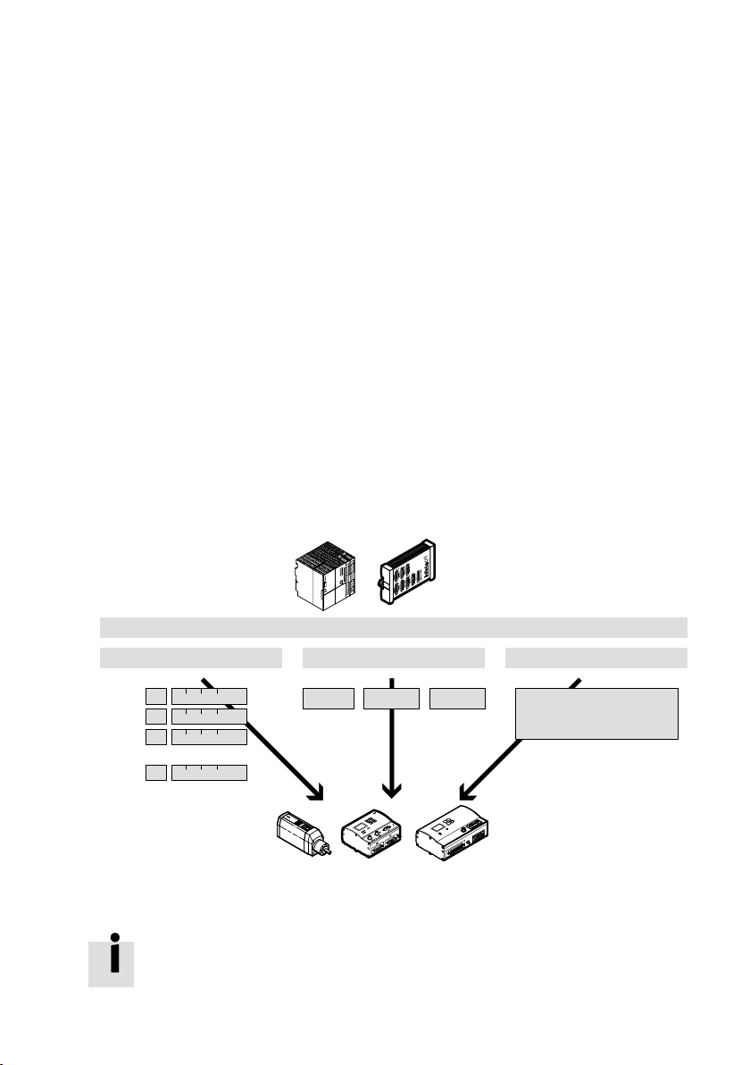
1.3 Festo Profile for Handling and Positioning (FHPP)
Festo has developed an optimized data profile especially
tailored to the target applications for handling and position
ing tasks, the Festo Handling and Positioning Profile
(FHPP)".
The FHPP enables uniform control and programming for the
various field bus systems and controllers from Festo.
In addition it defines the following for the user:
the operating modes
the I/O data structure
the parameter objects
the sequence control.
. . .
Record Select
1
>
2
3
...
n
Fig.1/1: The FHPP principle
Festo P.BE−SFC−DC−PB−S7−E N en 0604NH
Field bus communication
Direct mode Parameter channel
Mode PositionSpeed
Free acces to all
parameters
reading and writing
. . .
Detailed information on the FHPP can be found in
appendixA.1.
1−5
Page 28

1. Overview
Control and status bytes
Control via the field bus is made via 8 bits of I/O data.
Functions and status messages required in operation can be
conntrolled directly mostly with single−bit operations.
Record Select
Saved position sets can be processed in the Record Select
mode.
For this purpose, up to 31 position sets
are parametrized with
the Festo Configuration Tool or taught via the control panel
during commissioning.
Direct mode
In the Direct operating mode the important positioning data
are transferred directly via the control bytes.
1−6
Target positions and speeds can be ascertained and
specified by the controller during running time, depend
ing on the operating status.
limitations due to the number of saved position sets.
No
In both operating modes values can be taught/parametrized
via the PLC.
Parameter channel
By means of the parameter channel, the controller can access
all parameter values of the controller via the field bus.
A further 8 bytes of I/O data are used for this
Festo P.BE−SFC−DC−PB−S7−E N en 0604NH
purpose.
Page 29

Installation and project overwiev
Chapter 2
2−1Festo P.BE−SFC−DC−PB−S7−EN en 0604NH
Page 30

2. Installation and project overwiev
Contents
2. Installation and project overview 2−1 . . . . . . . . . . . . . . . . . . . . . . . . . . . . . . . . .
2.1 Configuration 2−3 . . . . . . . . . . . .
2.1.1 Install device master file (GSD file) and icon files 2−3 . . .
2.1.2 I/O configuration 2−4 . . . . . . . . . . . . . . . . . . . . . . . . . . . . . . . . . . . . . .
2.1.3 Configuration with STEP 7 2−5 . . . . . . . . . . . . . . . . . . . . . . . . . . . . . . . . .
2.2 Dearchivating the example project 2−10 . . . . . . .
2.3 Overview of project 2−12 . . . . . . . . . . . . . . . . . . . . . .
2.3.1 Folder _CTRL" control functions 2−12 . . . . . . . . . . . . . . . . . . . . . .
2.3.2 Folder _PRM_FPC" parametrizing via FPC 2−13 . . . . . . . . . . . . . . . . . .
2.3.3 Folder PRM_DPV1_SFB" parametrizing via DPV1 2−14 . . . . . . . . . . . .
2.3.4 Folder PRM_DPV1_SFC" parametrizing via
2.3.5 Folder PRM_UP−DOWNLOAD"
transmitting several parameters 2−16 . . . . . . . . . . . . . . . . . . . . . . . . . . .
. . . . . . . . . . . . . . . . . . . . . . . . . . . . . . . . . . . . . .
. . . . . . . . . . . . . . . . . . . . . . . . . .
. . . . . . . . . . .
. .
. . . . . . . . . . . . . . . . . . . . . . .
. . . .
DPV1 2−15 . . . . . . . . . . . .
2−2
Festo P.BE−SFC−DC−PB−S7−EN en 0604NH
Page 31

2. Installation and project overwiev
2.1 Configuration
2.1.1 Install device master file (GSD file) and icon files
If a new hitherto unknown device is to be incorporated in a
configuration program when a PROFIBUS−DP system is to be
configured, an appropriate device master file (GSD file)
must be installed for this device. The device master file
contains all the necessary information for the configuration
program. You will require the appropriate
representing the device graphically.
Obtainable This documentation CD of the SFC−DC contains GSD files and
icon files for the SFC−DC in the folder PROFIBUS".
Current GSD files and icon files can be found on the Festo
Internet pages under:
www.festo.com/fieldbus
icon files for
GSD file You will require one of the following GSD files for the
SFC−DC:
SFC_0973.gsd English
SFC_0973.gsg German
(with support DPV0 and DPV1)
SFC00973.gsd English
SFC00973.gsg German
(only for older controllers/without DPV1)
Icon files In order to represent the SFC−DC in your configuration
software use the following icon files:
Festo P.BE−SFC−DC−PB−S7−EN en 0604NH
2−3
Page 32

2. Installation and project overwiev
2.1.2 I/O configuration
Normal operating
status
File: sfc−dc_n.dib or
sfc−dc_n.bmp
Diagnostic case Special operating
status
File: sfc−dc_d.dib or
sfc−dc_d.bmp
File: sfc−dc_s.dib or
sfc−dc_s.bmp
Tab.2/1: Icon files
Two configurations are supported by the GSD files:
Festo handling and positioning profile standard"
GSD entry as FHPP Standard",
8 bytes of I/O data, consistent transmission
Festo handling and positioning profile with parameter
channel"
GSD entry as FHPP Standard + FPC",
2 x 8 bytes of I/O data, consistent transmission
2−4
Festo P.BE−SFC−DC−PB−S7−EN en 0604NH
Page 33

2. Installation and project overwiev
2.1.3 Configuration with STEP 7
General instructions
The software package SIMATIC Manager serves for project
planning and commissioning in conjunction with PROFIBUS
masters from Siemens or compatible masters. In order to
understand this chapter, you should be sure of how to handle
your configuration program. If necessary, refer to the docu
mentation for the SIMATIC Manager. This manual refers
software version V 5.3.
An appropriate device master file (GSD file) for the SFC−DC
must be installed for configuration.
With the STEP 7 Hardware Configurator you can load the files
via the menu command [Options] [Install GSD file] in the dia
logue window HWConfig".
to
Configuration program
STEP 7 Hardware Configurator 1)GSD file ...\STEP7\S7DATA\GSD
1)
If you copy the GSD files when the SIMATIC Manager has already been started, you can update the
hardware catalogue with the command [Options] [Update Catalog].
File type Directory
Bitmap files ...\STEP7\S7DATA\NSBMP
Tab.2/2: Folder for GSD and icon files STEP 7
Festo P.BE−SFC−DC−PB−S7−EN en 0604NH
2−5
Page 34

2. Installation and project overwiev
Insert SFC−DC as slave
The hardware configuration window represents graphically
the structure of the master system. When the GSD file has
been installed, the SFC−DC can be selected in the hardware
catalogue. It can be found in the group [PROFIBUS−DP]
[Additional Field Devices] [Drives] [Festo], (see Fig.2/1).
In order to insert the SFC−DC:
1. Drag
the station type Festo SFC−DC" or Festo SFC−DC
DP−V0" (3, see section 2.1.1) from the hardware
catalogue onto the PROFIBUS line (1) of the DP master
system (Drag & Drop).
2. Enter the PROFIBUS address, which you have set with the
Festo Configuration Tool or on the control panel in the
dialogue window
Properties PROFIBUS interface..." and
confirm with OK.
3. If necessary, enter other settings in the dialogue window
Properties DP slave" (e.g. the response monitoring or
the startup parametrizing) and confirm with OK.
The icon of the SFC−DC is displayed on the line of the DP
master system (2).
2−6
Festo P.BE−SFC−DC−PB−S7−EN en 0604NH
Page 35

2. Installation and project overwiev
1 23
1 PROFIBUS line
2 Icon for SFC−DC
Fig.2/1: Station selection STEP 7
Festo P.BE−SFC−DC−PB−S7−EN en 0604NH
3 Enter Festo SFC−DC from GSD file
2−7
Page 36

2. Installation and project overwiev
Configuring the slave features
After clicking the icon for the SFC−DC, you can configure the
Slave properties" in the lower part of the screen. Here you
can determine the number and size of the I/O ranges of the
slave and assign them with address ranges of the master.
In order to configure the
slave properties of the SFC−DC:
1. Open the available modules (configurations) in the hard
ware catalogue under [Festo SFC−DC ...].
2. Then drag the desired configuration (see section 2.1.2)
with the mouse into the appropriate line under Compo
nent/DP identifier.
With STEP 7 a Universal module" is also offered for
compatibility reasons. This must not be
used.
The SFC−DC is a modular slave, but with only one permitted
module. The configuration is defined only by the master.
2−8
Festo P.BE−SFC−DC−PB−S7−EN en 0604NH
Page 37

2. Installation and project overwiev
123
1 DP identifiers
2 I/O address range
Fig.2/2: Configuring the slave features
When the configuration is concluded, transfer the data to the
master.
Festo P.BE−SFC−DC−PB−S7−EN en 0604NH
3 Modules (configurations)
2−9
Page 38

2. Installation and project overwiev
2.2 Dearchivating the example project
The example project will be made available as project
archive.
Procedure for dearchivating
1. Open the dialogue Retrieving Select an archive" with
the command [File] [Retrieve] ([File] [Dearchivate]).
2−10
Fig.2/3: Dearchivate project
2. Select the archive file of the example project
(e.g. SFC−DC.zip").
3. Select the desired destination path in the dialogue
Select destination directory".
If the option Scan destination directory when dearchivat
ing" is switched off in the basic settings of the SIMATIC
Manager, the preset path will be used directly as the des
tination path during dearchivation.
4. The unpacking of the project will be shown in a DOS or
console window. The project will then be opened in the
SIMATIC Manager:
Festo P.BE−SFC−DC−PB−S7−EN en 0604NH
Page 39

2. Installation and project overwiev
Fig.2/4: Folder S7 program" of the example project
The example project does not contain any hardware. You can
use this in your controller in one of the following ways:
Drag the modules required into your own control project.
Add the relevant hardware to the example project. Delete
non−required S7 program" folders.
Festo P.BE−SFC−DC−PB−S7−EN en 0604NH
In each case adapt
the addresses to your controller.
2−11
Page 40

2. Installation and project overwiev
2.3 Overview of project
The following sections contain an overview of the
S7program" folders of the example project.
2.3.1 Folder _CTRL" control functions
The most important blocks in the folder _CTRL" for
controlling the controller are listed in Tab.2/3.
Additional blocks, e.g. for fault treatment or data blocks, etc.
are not listed.
Block
OB1 Main Cyclic program
FB10 SFC_DC_CTRL Control FB for controlling the
DB90 GV−SFC Control Contains the global
SFC_CTRL−DRIVE Control Variable table for control Example
Name Purpose Description Access Function
access
Main program routine FB10 Example
SFC14/15 Festo control
drive
Example
control variables for FB10
project
block
project
project
Tab.2/3: Overview of the most important blocks of the folder _CTRL"
Block FB10 for controlling the SFC−DC is implemented in OB1.
The global variables for controlling the controller are saved in
DB90. With the aid of the variable table SFC_DC−CTRL the
drive can be positioned via PROFIBUS.
2−12
Festo P.BE−SFC−DC−PB−S7−EN en 0604NH
Page 41

2. Installation and project overwiev
2.3.2 Folder _PRM_FPC" parametrizing via FPC
The most important blocks in the folder _PRM_FPC" for
parametrizing the controller via the Festo Parameter Channel
(DPV0) are listed in Tab.2/4.
Additional blocks, e.g. for fault treatment or data blocks, etc.
are not listed.
Block
OB1 Main Cyclic program
FB20 PRM_FPC Parametrizing
DB91 GV−PRM Parametrizing Contains the global control
PARAMETERIZE−DRIVE Parametrizing Variable table for
Name Purpose Description Access Function
access
(DPV0)
Main program routine FB20 Example
FB for parametrizing via
FPC
variables for parametrizing
parametrizing
SFC14/15 Festo control
Example
Example
Tab.2/4: Overview of the most important blocks of the folder _PRM_FPC"
Block FB20 for parametrizing the SFC−DC via DPV0 is implem
ented in OB1. The global variables for parametrizing are
saved in DB91. With the aid of the variable table PARAMETER
IZE−DRIVE the controller can be parametrized via PROFIBUS.
project
block
project
project
Festo P.BE−SFC−DC−PB−S7−EN en 0604NH
2−13
Page 42

2. Installation and project overwiev
2.3.3 Folder PRM_DPV1_SFB" parametrizing via DPV1
The most important blocks in the folder PRM_DPV1_SFB" for
parametrizing the controller via DPV1 are listed in Tab.2/5.
Additional blocks, e.g. for fault treatment or data blocks, etc.
are not listed.
Block
OB1 Main Cyclic program
FB21 PRM_DPV1_SFB Parametrizing
DB91 GV−PRM Parametrizing Contains the global
PARAMETERIZE−DRIVE Parametrizing Variable table for
Name Purpose Description Access Function
access
(DPV1)
Main program routine FB21 Example
FB for parametrizing
via DPV1 using
SFB52/53
control variables for
parametrizing
parametrizing
SFB52/53 Festo control
Example
Example
project
block
project
project
Tab.2/5: Overview of the most important blocks of the folder PRM_DPV1_SFB"
Block FB21 for parametrizing the SFC−DC via DPV1 is
implemented in OB1. The global variables for parametrizing
are saved in DB91. With the aid of the variable table
PARAMETERIZE−DRIVE the controller can be parametrized via
PROFIBUS.
2−14
Festo P.BE−SFC−DC−PB−S7−EN en 0604NH
Page 43

2. Installation and project overwiev
2.3.4 Folder PRM_DPV1_SFC" parametrizing via DPV1
The most important blocks in the folder PRM_DPV1_SFC" for
parametrizing the controller via DPV1 are listed in Tab.2/6.
Additional blocks, e.g. for fault treatment or data blocks, etc.
are not listed.
Block
OB1 Main Cyclic program
FB22 PRM_DPV1_SFB Parametrizing
DB91 GV−PRM Parametrizing Contains the global
PARAMETERIZE−DRIVE Parametrizing Variable table for
Name Purpose Description Access Function
access
(DPV1)
Main program routine FB22 Example
FB for parametrizing
via DPV1 using
SFC58/59
control variables for
parametrizing
parametrizing
SFC58/59 Festo control
Example
Example
project
block
project
project
Tab.2/6: Overview of the most important blocks of the folder PRM_DPV1_SFC"
Block FB22 for parametrizing the SFC−DC via DPV1 is
implemented in OB1. The global variables for parametrizing
are saved in DB91. With the aid of the variable table
PARAMETERIZE−DRIVE the controller can be parametrized via
PROFIBUS.
Festo P.BE−SFC−DC−PB−S7−EN en 0604NH
2−15
Page 44

2. Installation and project overwiev
2.3.5 Folder PRM_UP−DOWNLOAD" transmitting several parameters
The most important blocks in the folder UP−DOWNLOAD" for
transmitting several parameters are listed in Tab.2/6.
Additional blocks, e.g. for fault treatment or data blocks, etc.
are not listed.
Block
OB1 Main Cyclic program
FB1 UP−DOWN Parametrizing Function block contains
FB20 PRM_FPC Parametrizing
FB23 PRM_DB−FILE Parametrizing
DB91 GV−PRM Parametrizing Contains the global control
DIAGNOSTIC BUFFER Parametrizing Variable table for reading
PARAMETERIZE−DRIVE Parametrizing Variable table for
Name Purpose Description Access Function
access
(DPV0)
(DPV0/DPV1)
Main program routine FB1 Example
examples of routines for
exchanging parameter sets
FB for parametrizing via
FPC
FB controls the upload/
download of parameter
sets from a global DB via
one of the three trans
mission paths
variables for parametrizing
out the diagn. memory
parametrizing
FB20,
FB23
SFC14/15 Festo control
SFC24 Festo control
Example
Example
Example
project
Example
project
block
block
project
project
project
Tab.2/7: Overview of the most important blocks of the folder PRM_DPV1_SFC"
Block FB1 is implemented in OB1. Block FB23 for transmitting
parameter sets as well as block FB20 for parametrizing the
SFC−DC via the Festo Parameter Channel (DPV0) are implem
ented in FB1. This is also possible via the blocks FB21 or
FB22.
The global
variables for parametrizing are saved in DB91.
With the aid of the variable table PARAMETERIZE−DRIVE the
controller can be parametrized via PROFI BUS. The diagnostic
memory can be read out with the variable table DIAGNOSTIC
BUFFER.
2−16
Festo P.BE−SFC−DC−PB−S7−EN en 0604NH
Page 45

Control block
Chapter 3
3−1Festo P.BE−SFC−DC−PB−S7−EN en 0604NH
Page 46

3. Control block
Contents
3. Control block 3−1 . . . . . . . . . . . . . . . . . . . . . . . . . . . . . . . . . . . . . . . . . . . . . . . . . .
3.1 Function block SFC_DC_CTRL" 3−3 . . . . . . . . . . . . . . . . . . . . . . . . . . . . . . . . . . .
3.1.1 Description of method of operation 3−4 . . . . . .
3.1.2 Input parameters 3−6 . . . . . . . . . . . . . . . . . . . . . . . . . . . . . .
3.1.3 Output parameters 3−8 . . . . . . . . . . . . . . . . . . . . . . . . . . . . . . . . . . . . . .
3.1.4 Fault information 3−10 . . . . . . . . . . . . . . . . . . . . . . . . . . . . . . . . . . . . . . . .
. . . . . . . . . . . . . . . . . . .
. . . . . . . . . .
3−2
Festo P.BE−SFC−DC−PB−S7−EN en 0604NH
Page 47

3. Control block
3.1 Function block SFC_DC_CTRL"
The SFC−DC is controlled with block SFC_DC_CTRL.
Fig.3/1: SFC−DC control block
Festo P.BE−SFC−DC−PB−S7−EN en 0604NH
3−3
Page 48

3. Control block
3.1.1 Description of method of operation
The block enables the drive functions of the SFC−DC to be
controlled by the field bus. It enables comfortable access to
the control bits.
System functions used
For data exchange the block uses internally the system func
tions SFC14/SFC15.
The correct logical input and output addresses of the slave
projected in the Hardware Manager must be entered for the
data exchange.
Position factor
All position specifications are always saved internally in
increments in the SFC−DC.
In the control block the conversion between increments and
the desired measuring system takes place via a position fac
tor. The position factor is defined by a counter and a denomi
nator value.
Unit of length
Increments Pos_Faktor_nummerator:
m Pos_Faktor_nummerator:
Inch Pos_Faktor_nummerator:
Parameter SLTE−10 SLTE−16
Pos_Faktor_denummerator:
Pos_Faktor_denummerator:
Pos_Faktor_denummerator:
1000000
1000000
1795938 (default)
1000000
45616836
1000000
1000000
1000000
2338461
1000000
59396923
1000000
Tab.3/1: SFC−DC position factors with the electric mini−slide type SLTE
3−4
Festo P.BE−SFC−DC−PB−S7−EN en 0604NH
Page 49

3. Control block
If both factors are 1, the current position and the nominal
value for the position will be specified in increments.
The values for specifying the positions in m are saved in
the SFC−DC and can be downloaded (PNU 1004, subindex 0
and 1).
Device control
In order that the drive can be controlled via the PLC, the
device control via the PROFIBUS interface must be active.
Control via the FCT or the control panel must be deactivated
(Reurn message−Bit Drive_Control_FCT_HMI = 0).
The drive is ready to operate when the bits Stop, Halt and
Enable_Drive = 1 and
bits Drive_Enabled and Ready = 1.
the Fault bit = 0. This is shown with the
Festo P.BE−SFC−DC−PB−S7−EN en 0604NH
3−5
Page 50

3. Control block
3.1.2 Input parameters
Parameter Declar
ation
I_ADDRESS INPUT WORD Address of the logical inputs of the slave.
O_ADDRESS INPUT WORD Address of the logical outputs of the slave.
Pos_Factor_
numerator
Pos_Factor_
denumerator
HMI_Access_
Locked
Reset_Fault INPUT BOOL With a rising edge a fault is quitted and the fault number is
Halt INPUT BOOL Halt drive.
INPUT INT Counter of the position factor (default 1)
INPUT INT Denominator of the position factor (default 1)
INPUT BOOL Controls access to the local (integrated) diagnostic
Data
type
Description
interface of the drive.
TRUE: MMI and FCT may only observe the drive, the
device control (HMI control) cannot be taken over
by MMI and FCT.
FALSE: MMI or FCT may take over the device control (in
order to modify parameters or to control inputs)
deleted.
TRUE: Halt is not active.
FALSE: Halt activated (do not cancel braking ramp +
positioning task). The axis stops with a defined
braking ramp, the positioning task remains active
(the remaining path can be deleted with
Clear_remaining_Position").
Stop INPUT BOOL Stop / enable operation.
TRUE: Enable operation.
FALSE: Stop active (cancel emergency ramp + positioning
task). The axis stops with maximum braking ramp,
the positioning task is reset.
Enable_Drive INPUT BOOL Enable drive.
TRUE: Enable drive (controller). Faults will be deleted.
FALSE: Drive (controller) blocked.
Start_Homing INPUT BOOL Start reference travel
With a rising edge reference travel with the set
parameters is started.
3−6
Festo P.BE−SFC−DC−PB−S7−EN en 0604NH
Page 51

3. Control block
Parameter DescriptionData
Start_Task INPUT BOOL Start current task.
Operation_Mode INPUT BOOL Selecting the operating mode
Absolute_Relative INPUT BOOL Positioning mode
Clear_Remaining_
Position
Jog_pos INPUT BOOL Jogging positive
Jog_neg INPUT BOOL Jogging negative
Teach_Actual_
Value
Declar
ation
INPUT BOOL Deletes the unfinished positioning task after a stop.
INPUT BOOL Teach th ecurrent position, see appendix A.2.4.
type
With a rising edge the current nominal values will be
transferred and positioning started (record 0 = reference
travel).
FALSE: Record Select
TRUE: Direct mode
FALSE: Nominal value is absolute.
TRUE: Nominal value is relative to last nominal value
In the Halt" status, a positive signal edge causes the
positioning task to be deleted and transfer to the Ready"
status.
The drive moves at the specified speed in the direction of
larger actual values, providing the bit is set. The movement
begins with the rising edge and ends with the falling edge.
The drive moves at the specified speed in the direction of
smaller actual values, see Jog_neg".
The Teach target is defined with PNU 520.
Record_No INPUT INT Preselect of record number for Record Select
Set_Value_
Velocity
Set_Value_
Position
INPUT INT Preselect of speed for direct mode
INPUT DINT Preselect of position for direct mode:
(1 ... 31, 0 = reference travel).
(in % of the maximum speed)
position in measured unit, depends on position factor.
Tab.3/2: Input parameter SFC_DC_CTRL"
Festo P.BE−SFC−DC−PB−S7−EN en 0604NH
3−7
Page 52

3. Control block
3.1.3 Output parameters
Parameter Declar
ation
Control_FCT_HMI OUTPUT BOOL Control sovereignty PLC or MMI/FCT.
Drive_enabled OUTPUT BOOL Drive enabled.
Supply_Voltage_OkOUTPUT BOOL Load voltage
Warning OUTPUT BOOL Warning.
Fault OUTPUT BOOL Fault
Ready OUTPUT BOOL Quit stop, if Drive_enable" = 1
State_Operation_
Mode
Ack_Start OUTPUT BOOL Quit Start
OUTPUT BOOL Reply message operating mode
Data
type
Description
FALSE: Control sovereignty PLC
TRUE: Control sovereignty MMI/FCT (PLC control is
Locked).
FALSE: Drive blocked, controller not active.
TRUE: Drive (controller) enabled.
FALSE: No load voltage
TRUE: Load voltage applied
FALSE: Warning not applied
TRUE: Warning applied
FALSE: No fault
TRUE: There is a fault or reaction to fault is active.
Fault number in diagnostic memory
FALSE: Record Select (standard)
TRUE: Direct mode
FALSE: Ready for start (reference, jog)
TRUE: Start carried out (reference, jog)
Ack_Teach OUTPUT BOOL Quit Teach
positive edge: Ready for teaching
negative edge: Teaching carried out
3−8
Actual value is transferred.
Festo P.BE−SFC−DC−PB−S7−EN en 0604NH
Page 53

3. Control block
Parameter DescriptionData
MC OUTPUT BOOL Motion Complete
Drive_is_moving OUTPUT BOOL Axis moves
Halt_Not_Active OUTPUT BOOL Reply message Halt
Drag_Error OUTPUT BOOL Drag error
Standstill_Control OUTPUT BOOL Standstill monitoring
Drive_is_
referenced
Declar
ation
OUTPUT BOOL Axis referenced.
type
FALSE: Positioning task active
TRUE: Positioning task completed, if applicable with
fault
Note: MC is set after device is switched on
(status Drive blocked")
FALSE: Speed of the axis < Limit value
TRUE: Speed of the axis > = limit value
FALSE: Halt is active, at start last positioning task will
be continued.
TRUE: Halt is not active, axis can be moved.
FALSE: No drag error.
TRUE: Drag error active.
FALSE: After MC axis remains in tolerance window.
TRUE: Achse steht nach MC außerhalb Toleranzfenster.
FALSE: Referencing must be carried out.
TRUE: Reference information exists, reference travel
must not be carried out.
Actual_Record_No OUTPUT INT Reply message of record number for Record Select
(1...31, 0 = reference travel).
Actual_Velocity OUTPUT BYTE Reply message of speed for Direct mode
(in % of the maximum speed)
Actual_Position OUTPUT DINT Reply message of the position.
Position, depends on position factor (see Tab.3/1).
RET_VAL OUTPUT INT Reply value of the function block.
Tab.3/3: Output parameter SFC_DC_CTRL"
Festo P.BE−SFC−DC−PB−S7−EN en 0604NH
3−9
Page 54

3. Control block
3.1.4 Fault information
The fault output of the block distinguishes between faults in
the SFC−DC and faults in the block. Faults in the SFC−DC are
shown with the Fault bit, more precise details of the fault
must be downloaded in the diagnostic buffer of the SFC−DC.
Block faults are output at the output RET_VAL. If the
block is
processed incorrectly, the ENO bit will be set to 0.
Block−internal faults are triggered by a position factor
denummerator with value 0, or by system functions
(e.g.SFC14/SFC15, ...).
The fault codes are defined by the transmission blocks, seeh
elp for STEP 7.
The evaluation of the fault can take place with the
value
RET_VAL and the help for the relevant transmission blocks
(SFC14/SFC15, SFB52/SFB53, SFC58/SFC59).
3−10
Festo P.BE−SFC−DC−PB−S7−EN en 0604NH
Page 55

Parametrizing blocks
Chapter 4
4−1Festo P.BE−SFC−DC−PB−S7−EN en 0604NH
Page 56

4. Parametrizing blocks
Contents
4. Parametrizing blocks 4−1 . . . . . . . . . . . . . . . . . . . . . . . . . . . . . . . . . . . . . . . . . . .
4.1 Overview of parametrizing blocks 4−3 . .
4.1.1 Control and parametrizing methods 4−4 . . . . . . . . . . . . . .
4.1.2 Method of operation of the blocks 4−4 . . . . . . . . . . . . . . . . . . . . . . . . . .
4.1.3 Converting the measuring units 4−5 . . . .
4.2 Block PRM_FPC 4−6 . . . . . . . . . . . . . . . . . . . . . . . .
4.2.1 Input parameters 4−7 . . . . . . . . . . . . . . . . . . . . . . . . .
4.2.2 Output parameter 4−7 . . . . . . . . . . . . . . . . . . . . . . . . . . . . . . . . .
4.3 Blocks PRM_DPV1_SFB / PRM_DPV1_SFC 4−8 . . . . . . . . . . . . . . . . . . . . . . . . . .
4.3.1 Input parameters 4−9 . . . . . . . . . . . . .
4.3.2 Output parameters 4−9 . . . . . . . . . . . . . . . . . . . . .
4.4 Block PRM_DB−FILE 4−10 . . . . . . . . . . . . . . . . . . . . . . . . . . . . . . . .
4.4.1 Description of method of operation 4−11 . . . . . . . . . . . . . . . . . . . . . . . . .
4.4.2 Input parameters 4−13 . . . . .
4.4.3 Output parameters 4−14 . . . . . . . . . . . . . .
4.4.4 Implementation 4−15 . . . . . . . . . . . . . . . . . . . . . . . . .
4.4.5 Restriction 4−15 . . . . . . . . . . . . . . . . . . . . . . . . . . . . . . . . . .
4.5 Fault information 4−16 . . . . . . . . . . . . . . . . . . . . . . . . . . . . . . . . . . . . .
. . . . . . . . . . . . . . . . . . . . . . . . . . . . . . . .
. . . . . . . . . . .
. . . . . . . . . . . . . . . . . . . . . . . .
. . . . . . . . . . . . . . . . . . . . . . . .
. . . . . . . . . . . . . . .
. . . . . .
. . . . . . . . . . . . . . . . . . . . . . . . . . .
. . . . . . . . . . . . . . . . .
. . . . . . . . . . . . .
. . . . . . . . . . . . . . . . . . . . . . . . . . . . . . . . . . .
. . . . . . . . . . . . . . . . . . . . . . . .
. . . . . . . . . . . . . . . .
. . . . . . . . . . .
. . . . . . . . . .
4−2
Festo P.BE−SFC−DC−PB−S7−EN en 0604NH
Page 57

4. Parametrizing blocks
4.1 Overview of parametrizing blocks
For parametrizing the SFC−DC, different methods can be used
depending on the blocks:
parametrizing with the block PRM_FPC via the cyclic data
(DPV0)
parametrizing with the block PRM_DPV1_SFB using the
system function blocks SFB52/SFB53 (DPV1)
parametrizing with the block PRM_DPV1_SFC using the
system functions SFC58/SFC59 (DPV1)
automatic transfer of several parameters with the block
PRM_DB−FILE"
The choice of transfer method depends primarily on the con
troller used. Transfer via the cyclic data is possible with any
DP controller, but requires memory space in the logical ad
dress range, which can cause problems under certain circum
stances with many slaves on the bus.
and one of the parametrizing blocks.
Festo P.BE−SFC−DC−PB−S7−EN en 0604NH
the case of transfer via DPV1 with the system function
In
moules SFB52/SFB53 from Siemens, you must make sure
that this transfer procedure is supported by the controller.
With the system functions SFC58/SFC59 for older controllers,
Siemens therefore offers the possibility of transferring para
meters DV1−conform to the controller.
For compatibility reasons the block
interfaces of all transfer
types are identical.
Please note
All blocks address parameters with subindices as per
DPV1. This means that the subindices must be transferred
from 0 ... n−1.
4−3
Page 58

4. Parametrizing blocks
4.1.1 Control and parametrizing methods
DPV0 Parametrizing with the DPV0 is carried out via the Festo para
meter channel (FPC, further 8 I/O bytes), see manual for the
SFC−DC−...−PB.
DPV1 Die Parametrizing with the DPV1 is carried out via the para
meter channel as per PROFIdrive V3.1. This protocol is a com
patible extension of the PKW protocol within the
data. This means that the parameters can be addressed with
PNU, subindex etc.
DPV1 work
4.1.2 Method of operation of the blocks
With all blocks a parameter is clearly defined by the PNU
(parameter number), the subindex and the length in bytes.
4−4
With the blocks named under 4.1 only one parameter can be
transferred in each case. With the bit RD_WR you can define
whether the parameter is to be read or written. When the
parameters are transferred, a distinction is made between
three data types: Byte, Word, Double word or length 1, 2, 4.
How the parameter is to be interpreted can be found in the
description of the relevant parameter, see manual for the
controller used.
An overview of the parameters can be found in appendix
It is not necessary to specify the length of the parameter in
order that it can be read.
A positive edge at the start input triggers the transfer. When
the transfer is completed, this will be shown at the output
Done. The result of the transfer is shown all the time the
bit is set to 1.
The reply to an incorrect parameter entry depends on the
transmission method.
Festo P.BE−SFC−DC−PB−S7−EN en 0604NH
B.1.
start
Page 59

4. Parametrizing blocks
4.1.3 Converting the measuring units
In the SFC−DC all parameters are always saved in increment
specifications (inc, inc/s, inc/s
2
). Conversion is carried out via
the parameters:
Feed constant, depending on the drive
Gear reduction
Encoder resolution = physical measuring steps per motor
revolution. With the SFC−DC: pulse quadruplication by
digital interpolation.
Parameters
feed Feed constant
gear Gear ratio
enc Encoder resolution
1) D
epending on drive, here type SLTE−...
2)
Specification in 2 natural numbers for counter or denominator of the fraction
3)
With the SFC−DC: pulse quadruplication by digital interpolation
1)
2)
3)
SLTE−10 SLTE−16
SLTE−...−BS5.0: 5000 [m/rev] SLTE−...−LS7.5: 7500 [m/rev]
SLTE−...−G04 (57:13)
512 x 4 = 2048 [incr/rev] 1000 x 4 = 4000 [incr/rev]
Tab.4/1: Basis parameter for the measuring system
The values for specifying the positions in m are saved in the
SFC−DC and can be downloaded (PNU 1004, subindex 0 and 1).
Special conversion factors for the SFC−DC
Length unit SLTE−10 SLTE−16
Increments > millimetres Increments / 1795.938 Increments / 2338.461
Millimetre > increments Millimetres * 1795.938 Millimetres * 2338.461
Increments > inch Increments / 45616.836 Increments / 59396.923
Inch > increments Inch * 45616.836 Inch * 59396.923
Tab.4/2: Conversion factors for SLTE measuring system
Festo P.BE−SFC−DC−PB−S7−EN en 0604NH
4−5
Page 60

4. Parametrizing blocks
4.2 Block PRM_FPC
The block transfers the parameters internally to the FPC
(Festo Parameter Channel).
Fig.4/1: Parametrizing via the cyclic data
4−6
Fault treatment
Transmission faults are displayed with the Fault bit, the para
meter Length_RD then contains value 2.
The cause of the fault will be output at Value_RD.
Information on faults can be found in section 4.5.
Festo P.BE−SFC−DC−PB−S7−EN en 0604NH
Page 61

4. Parametrizing blocks
4.2.1 Input parameters
Parameters Decla
ration
I_ADDRESS INPUT WO RD Logical input address of the FPC (PKW) specifications
O_ADDRESS INPUT WO RD Logical output address of the FPC (PKW) specifications
RD_WR INPUT BOOL FALSE: Read
Start INPUT BOOL Starts write or read procedure
PNU INPUT WORD Parameter number of the current parameter
Subindex INPUT BYTE Subindex of the current parameter
Length INPUT INT Length of the parameter to be written in bytes
Param_
Value_WR
INPUT DWORD Parameter value when writing a parameter
Data
type
Description
TRUE: Write
Tab.4/3: Input parameter PRM_FPC
4.2.2 Output parameter
Parameters Decla
ration
Data
type
Description
Done OUTPUT BOOL FALSE: Transfer completed
TRUE: Write
Value_RD OUTPUT DWORD Value of parameter to be read
Length_RD OUTPUT INT Length of parameter to be transferred
Fault OUTPUT BOOL FALSE: No fault
TRUE: Fault
RET_VAL OUTPUT INT Return value after incorrect processing of the block
Tab.4/4: Output parameter PRM_FPC
Festo P.BE−SFC−DC−PB−S7−EN en 0604NH
4−7
Page 62

4. Parametrizing blocks
4.3 Blocks PRM_DPV1_SFB / PRM_DPV1_SFC
The blocks PRM_DPV1_SFC and PRM_DPV1_SFB enable
transfer of parameters via DPV1.
The differences with the transfer via DPV1 are not recogniz
able externally or functionally. However, block
PRM_DPV1_SFC offers older controllers the possibility of
transferring parameters acyclically.
Fig.4/2: Parametrizing block with SFB52 / SFB53
Fig.4/3: Parametrizing block with SFC58 / SFC59
Fault treatment
Transmission faults are displayed with the Fault bit, the
parameter Length_RD then contains value 0x44 (68).
The fault number can be read at Value_RD.
Information on faults can be found in section 4.5.
4−8
Festo P.BE−SFC−DC−PB−S7−EN en 0604NH
Page 63

4. Parametrizing blocks
4.3.1 Input parameters
Parameters Decla
ration
I_O_ADDRESS INPUT WO RD Logical address of the DP slave module
RD_WR INPUT BOOL 0 = read
Start INPUT BOOL Starts write or read procedure
PNU INPUT WORD Parameter number of the current parameter
Subindex INPUT BYTE Subindex of the current parameter
Length_WR INPUT INT Length of the parameter to be written in bytes
Value_WR INPUT DWORD Parameter value when writing
Data
type
Description
Example: I−address 256, O−address 264
−−> W#16#100
The smaller of the two addresses must be specified.
1 = write
Tab.4/5: Input parameters PRM_DPV1_SFB / PRM_DPV1_SFC
4.3.2 Output parameters
Parameters Decla
ration
Data
type
Description
Done OUTPUT BOOL Transfer completed
Value_RD OUTPUT DWORD Value of parameter to be read
Length_RD OUTPUT INT Length of parameter to be transferred
Fault OUTPUT BOOL Fault bit
RET_VAL OUTPUT INT Return value after incorrect processing of the block
Tab.4/6: Output parameters PRM_DPV1_SFB / PRM_DPV1_SFC
Festo P.BE−SFC−DC−PB−S7−EN en 0604NH
4−9
Page 64

4. Parametrizing blocks
4.4 Block PRM_DB−FILE
In order to automate the transfer of several parameters, block
PRM_DB−FILE offers the possibility of transferring parameter
sets from a global DB to the controller or of receiving para
meter sets. The block uses one of the three transfer blocks
FB20, FB21 or FB22 for the transfer.
Block
PRM_FPC,
PRM_DPV1_SFC,
PRM_DPV1_SFB
List of the parameters for reading / writing
Individual parameter
DB Source
Block
PRM_DB−FILE
While i < n
PROFIBUS
Fig.4/4: System overview upload/download
4−10
Saving the parameters read
DB Target
Festo P.BE−SFC−DC−PB−S7−EN en 0604NH
Page 65
4. Parametrizing blocks
4.4.1 Description of method of operation
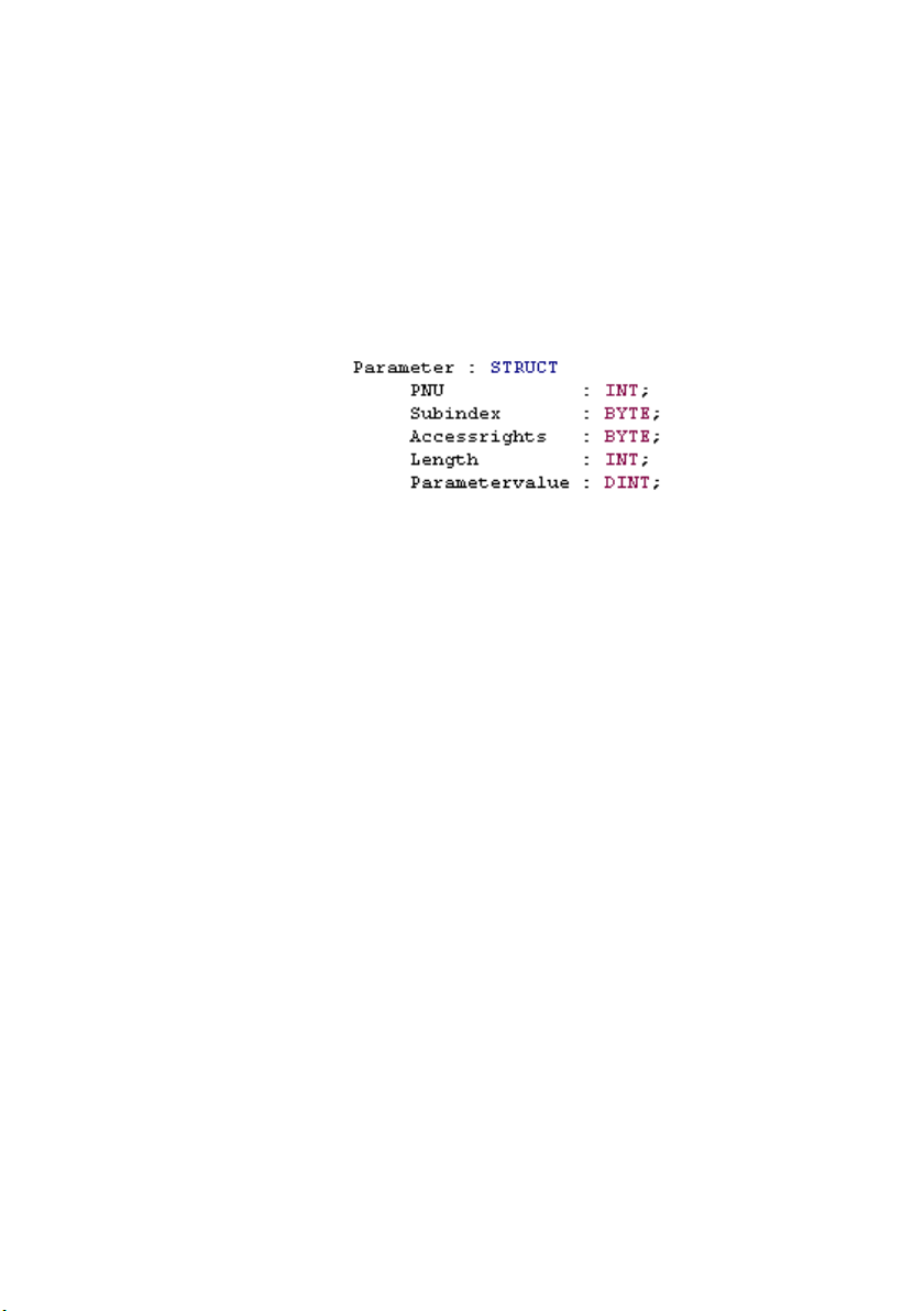
A list of the desired parameters must be saved in a global DB,
a parameter must be composed as follows:
Fig.4/5: Composition of a parameter
The byte Accessrights" is a reserve byte for additional
implementations, e.g. parameters with a certain identification
could be omitted from write−read authorization during
parametrizing.
The data block must correspond to an array of this structure
(n*10BYTE). A source and a target DB, which must be of the
ame length (n*10BYTE),
From the source DB you can read the parameters which are to
be read or written. In the case of reading, the read para
meters will then be transferred to the target DB. The same DB
can be specified for source and target. Only the parameter
values
will be transferred.
must be specifed for the transfer.
Festo P.BE−SFC−DC−PB−S7−EN en 0604NH
The data type for the parameter value always has the length
of a double word. It is therefore independent of the para
meter to be transferred. It occupies memory space but re
duces the problem in handling. If a parameter with length 1 is
transferred, the above−named three bytes will
be ignored.
Vice−versa when reading the above−named three byted will be
assigned with zeros. How the parameter value is to be inter
preted can be found in the description of the parameter.
The transmission is started with the bit Start_RxTx.
The progress of the transmission will be shown in % at the
Progress"
output. The transmission is completed when the
bit Done_RxTx supplies TRUE.
4−11
Page 66

4. Parametrizing blocks
If the parameter is faulty, the transmission will be aborted.
The fault can be identified by means of the incorrect
parameter values which are still present in the block.
Fig.4/6: Block for transferring a parameter list
4−12
Fault treatment
Transmission faults are shown with the Fault bit. The para
meter which caused the fault can be read with the last trans
ferred parameter values.
Information on faults can be found in section 4.5.
Festo P.BE−SFC−DC−PB−S7−EN en 0604NH
Page 67

4. Parametrizing blocks
4.4.2 Input parameters
Parameters Decla
ration
Start_RxTx INPUT BOOL Start transmission
Rx_Tx INPUT BOOL Read DB / write DB
DB_Source INPUT INT Source DB
DB_Target INPUT INT Target DB
_Done_RD_WR INPUT BOOL Transmission of individual parameters is concluded
_Fault_RD_WR INPUT BOOL Faults in the transmission of individual parameters
_Length_RD INPUT INT Length of the read parameter in BYTE
_Value_RD INPUT DWORD Parameter value of the current parameter when reading
Data
type
Description
Tab.4/7: Input parameter PRM_DB−FILE
Festo P.BE−SFC−DC−PB−S7−EN en 0604NH
4−13
Page 68

4. Parametrizing blocks
4.4.3 Output parameters
Parameters Decla
ration
_Start_R_WR OUTPUT BOOL Start transfer of individual parameters
_RD_WR OUTPUT BOOL Read/write individual parameter
_PNU OUTPUT INT PNU of the current parameter
_Subindex OUTPUT BOOL Subindex of the current parameter
_Length_WR OUTPUT INT Length of the current parameter in BYTE
_Value_WR OUTPUT DWORD Current parameter value to be written
Done_RxTx OUTPUT BOOL Read DB / write DB completed
Progress OUTPUT INT Progress of transmission in %
Fault_RxTx OUTPUT BOOL Fault with Read DB / write DB
RET_VALUE OUTPUT INT Return value after incorrect processing of the block
Data
type
Description
Tab.4/8: Output parameter PRM_DB−FILE
The block is ready to operate when the Done bit supplies
TRUE and there are no faults. Transmission is started with a
positive edge; the progress of the transmission is shown in
percent at the Progress" output. During transmission the
Done bit is set to FALSE.
4−14
Festo P.BE−SFC−DC−PB−S7−EN en 0604NH
Page 69

4. Parametrizing blocks
4.4.4 Implementation
The block PRM_DB−FILE cannot function on its own, only in
combination with one of the transfer blocks can it transfer a
list of parameters. Some of the inputs or outputs must there
fore be linked directly with each other.
4.4.5 Restriction
RD_WR_DB−FILE
_PNU OUTPUT −−> _PNU INPUT
_Subindex OUTPUT −−> _Subindex INPUT
_Length_RD OUTPUT −−> _Length INPUT
_Value_WR OUTPUT −−> _Value_WR INPUT
_Done_RD_WR INPUT <−− _Done_RD_WR OUTPUT
_Fault_RD_WR INPUT <−− _Fault_RD_WR OUTPUT
_Value_RD INPUT <−− _Value_RD OUTPUT
<−>
PRM_...
Tab.4/9: Wiring table
Function block RD_WR_DB−File uses internally the system
function SFC24. With this function the source and target DB
can be tested and their length defined. However, this function
is not implemented in controllers of an earlier date. The block
cannot therefrore be used there in this form.
Festo P.BE−SFC−DC−PB−S7−EN en 0604NH
4−15
Page 70

4. Parametrizing blocks
4.5 Fault information
A distinction is always made between two types of faults:
block faults and transmission faults.
Block faults (e.g. incorrect logic address, incorrect hardware
configuration, etc.) are caused by the relevant system func
tion blocks used SFC14/SFC15, SFC58/SFC59, SFB52/SFB53
or SFC24 and shown at the output R ET_VALUE. The fault code
can be found in the
STEP 7 help. If a block fault occurs, the
block will be exited with the ENO bit = 0.
Transmission faults arise as a result of incorrect parameter
data (e.g. non−existent PNU, incorrect parameter length when
writing, non−existent subindex, etc.).
Transmission faults are shown with the bit Fault.
With the aid of the
value of Value_RD the fault can be evalu
ated accordingly Tab.4/10.
Fault numbers
0 0x00 Non−permitted PNU The parameter does not exist.
1 0x01 Parameter value cannot be modified (read only)
(2) 0x02 (reserved lower or upper limit value exceeded)
3 0x03 Faulty subindex
4 0x04 No array
5 0x05 Incorrect data type
(6) 0x06 (reserved setting not permitted can only be reset)
(7) 0x07 (reserved describing element cannot be modified)
(8) 0x08 (reserved PPO−Write requested in IR does not exist)
9 0x09 Description data do not exist
(10) 0x10 (reserved access group incorrect)
11 0x0A No control sovereignty
(12) 0x0B (reserved password incorrect)
1)
These fault numbers are not used
Description
1)
1)
4−16
1)
1)
1)
1)
Festo P.BE−SFC−DC−PB−S7−EN en 0604NH
Page 71

4. Parametrizing blocks
Fault numbers Description
13 0x0C Text not legible in cyclic exchange
(14) 0x0D (reserved name not legible in cyclic exchange)
(15) 0x0E (reserved text array does not exist)
(16) 0x10 (reserved PPO−Write missing)
1)
1)
(17) 0x11 (reserved order cannot be processed because of operating status)
(18) 0x12 (reserved other faults)
1)
(19) 0x13 (reserved date not legible in cyclic exchange)
(20) 0x14 (reserved non−permitted value)
(21) 0x15 (reserved reply too long)
1)
1)
22 0x16 Non−permitted: Attributes, number of elements, PNU or IND
(23) 0x17 (reserved Write request: non−permitted format)
24 0x18 Write request: Number of values not permitted
(...99) 0x64 (reserved PROFIBUS)
100 0x65 (reserved Festo: ReqID is not supported)
(...255) 0xFF (reserved Festo)
1)
These fault numbers are not used
1)
1)
1)
1)
1)
Tab.4/10: Fault information
Festo P.BE−SFC−DC−PB−S7−EN en 0604NH
4−17
Page 72

4. Parametrizing blocks
4−18
Festo P.BE−SFC−DC−PB−S7−EN en 0604NH
Page 73

Examples
Chapter 5
5−1Festo P.BE−SFC−DC−PB−S7−EN en 0604NH
Page 74

5. Examples
Contents
5. Examples 5−1 . . . . . . . . . . . . . . . . . . . . . . . . . . . . . . . . . . . . . . . . . . . . . . . . . . . . .
5.1 Examples with the control block 5−3 . . . . . . . . . . . . . . . . . . . . . . . . . . . . . . . . . . .
5.1.1 Enable controller 5−4 . . . . .
5.1.2 Selecting the operating mode 5−5 . . . . . . . . . . . .
5.1.3 Starting a positioning task in direct mode 5−5 . . . . . . . . . . . . . . . . . . . .
5.1.4 Starting a positioning task in
5.2 Downloading a parameter list 5−8 . . . . . . . . . . . . . . . . . . . . . . . . . . . . . . .
. . . . . . . . . . . . . . . . . . . . . . . . . . . . . . . . . . .
. . . . . . . . . . . . . . . . . .
Record Select mode 5−7 . . . . . . . . . . . . .
. . . . . .
5−2
Festo P.BE−SFC−DC−PB−S7−EN en 0604NH
Page 75

5. Examples
5.1 Examples with the control block
In the following sections the variable table shows the values
which must be set in order to control certain functions of the
SFC−DC.
Festo P.BE−SFC−DC−PB−S7−E N en 0604NH
5−3
Page 76

5. Examples
5.1.1 Enable controller
With the bits Halt, Stop and Enable_Drive the readiness of
the controller to operate will be restored.
Fig.5/1: Enable controller
5−4
The readiness to operate will be shown with appropriate
return values.
Festo P.BE−SFC−DC−PB−S7−E N en 0604NH
Page 77
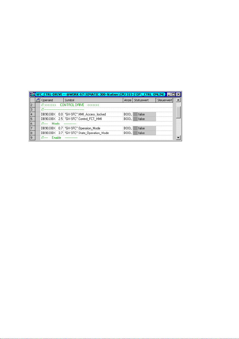
5. Examples
5.1.2 Selecting the operating mode
You can switch between the operating modes Record Select
and Direct mode via the bit Operation_Mode.
Fig.5/2: Setting the operating mode
5.1.3 Starting a positioning task in direct mode
In order to start a positioning task you must carry out
reference travel when the SFC−DC has been switched on. If
reference travel is successful, it will be shown with the bit
Drive_is_Referenced.
When the Direct mode has been set with the bit Operation_
Mode, the desired nominal position and nominal speed must
set with Set_Value_Position and Set_Value_Velocity.
be
Festo P.BE−SFC−DC−PB−S7−E N en 0604NH
5−5
Page 78

5. Examples
Fig.5/3: Positioning task in Direct mode
The positioning task is started with the bit Start_Task.
5−6
Festo P.BE−SFC−DC−PB−S7−E N en 0604NH
Page 79
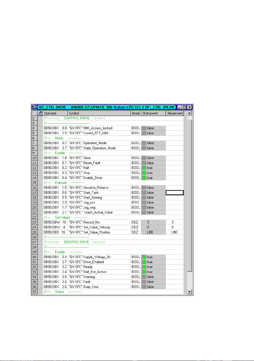
5. Examples
5.1.4 Starting a positioning task in Record Select mode
When the Record Select mode has been set with the bit
Operation_Mode, the positioning record saved in the SFC−DC
must be set with the value Record_No.
Fig.5/4: Preselecting the record number
The positioning task is started with the bit Start_Task.
Festo P.BE−SFC−DC−PB−S7−E N en 0604NH
5−7
Page 80

5. Examples
5.2 Downloading a parameter list
In the following the mechanism for downloading a list of
parameters is represented by the example of the positioning
record table.
Recommendation:
Edit the parameter list as an STL source.
Fig.5/5: Source of the parameter list
A positioning record consists of 5 parameters with the SFC−DC.
These parameters consist in turn of 5 variables which clearly
describe the parameter.
Parameter3 : STRUCT //Velocity_Setpoint
PNU : INT;
Subindex : BYTE;
accessrights : BYTE;
Length : INT;
Parametervalue : DINT;
5−8
Festo P.BE−SFC−DC−PB−S7−E N en 0604NH
Page 81

5. Examples
Festo P.BE−SFC−DC−PB−S7−E N en 0604NH
Fig.5/6: Parameter declaration in the parameter list
5−9
Page 82

5. Examples
5−10
Fig.5/7: Current values of the parameter list
If a list of parameters is defined, only the parameter value
must still be defined. When the current values of the individ
ual parameters have been entered, the data block can be
generated and loaded into the controller.
Festo P.BE−SFC−DC−PB−S7−E N en 0604NH
Page 83

5. Examples
Fig.5/8: Reply message from parameter transmission
Festo P.BE−SFC−DC−PB−S7−E N en 0604NH
When the source and target DBs are specified, the trans
mission can be started. If reference travel is successful, it will
be shown at the output Done.
5−11
Page 84

5. Examples
5−12
Festo P.BE−SFC−DC−PB−S7−E N en 0604NH
Page 85

Technical appendix
Appendix A
A−1Festo P.BE−SFC−DC−PB−S7−EN en 0604NH
Page 86

A. Technical appendix
Contents
A. Technical appendix A−1 . . . . . . . . . . . . . . . . . . . . . . . . . . . . . . . . . . . . . . . . . . . . .
A.1 Festo profile for handling
A.1.1 Supported operating modes A−3 . . . . . . . . . . . . . . . . . . . . . . .
A.2 Drive functions A−5 . . . . . . . . . . . . . . . . . . . . . . . . . . . . . . . . . . . . . . . . .
A.2.1 Reference system for electric drives A−5 . . . . . . . . . . . . . . . . . . . . . . . .
A.2.2 Reference travel A−7 . . . . . . . . . . .
A.2.3 Jogging A−9 . . . . . . . . . . . . . . . . . . . .
A.2.4 Teaching via field bus A−11 . . . . . . . . . . . . . . . . . .
A.2.5 Carry out record (Record Select) A−13 . . . . . . . . . . . . . . . . . . . . . . . . . . .
A.2.6 Specifying
A.2.7 Standstill monitoring A−21 . . . . . . . . . . . . . . . . . . . . . . . . .
A.3 Fault messages A−23 . . . . . . . . . . . . . . . . . . . . . . . . . . . . . . . . . . . . .
A.4 Diagnostic memory A−25 . . . . . . . . . . . . . . . . . . . . . . . . . . . . . . . . . . . .
A.5 Diagnosis via PROFIBUS−DP A−27 . . . . . . . . . . . . . . . . . . . . . . . . . . . . . . . . . . . . . .
A.5.1 Structure
and positioning (FHPP) A−3 . . . . . . . . . . . . . . . . . . . . .
. . . . . . . .
. . . . . . . .
. . . . . . . . . . . . . . . . . . . . . . . . . . . . . .
. . . . . . . . . . . . . . . . . . . . . . . . . . . .
. . . . . . . . . . . . . . . . . .
a position directly (Direct mode) A−18 . . . . . . . . . . . . . . . . . .
. . . . . . . . . . . .
. . . . . . . . . . . .
. . . . . . . . .
of the DP diagnosis A−27 . . . . . . . . . . . . . . . . . . . . . . . . . . . . . .
A−2
Festo P.BE−SFC−DC−PB−S7−EN en 0604NH
Page 87

A. Technical appendix
A.1 Festo profile for handling and positioning (FHPP)
The SFC−DC supports the Festo handling and positioning
profile FHPP (see also chapter 1.3).
A.1.1 Supported operating modes
The operating modes differ as regards their contents and the
meaning of the cyclic I/O data and in the functions which can
be accessed in the SFC−DC.
Operating mode
Record Select 31 position sets can be saved in the SFC−DC. A record contains all the para
Direct mode The positioning task is transferred directly in the I/O telegram. The most
Description
meters which are specified for a positioning task. The record number is
transferred to the cyclic I/O data as the nominal or actual value.
important nominal values (position, speed) are thereby transferred. Supple
mentary parameters (e.g. acceleration) are defined by the parametrizing.
Tab.A/1: Overview of operating modes
Record Select
Preset operating mode when the SFC−DC is started up.
The SFC−DC has 31 records (1 ... 31) which contain all the
information necessary for a positioning task (+ record 0 =
reference travel).
The record number, which the SFC−DC is to process at the
next start, is transferred to the output data of
The input data contains the last processed record number.
The positioning task itself does not need to be active.
the master.
Festo P.BE−SFC−DC−PB−S7−EN en 0604NH
A−3
Page 88

A. Technical appendix
The SFC−DC does not support any automatic mode, i.e. no
user program. Records cannot be processed automatically
with a programmed logic. The drive cannot accomplish any
tasks sensibly with Stand Alone; close coupling to the PLC is
necessary.
Direct mode
In the direct mode positioning tasks are formulated directly in
the output data of the master.
The typical application calculates dynamically the nominal
target values for each task or just for some tasks. Adaption to
different work item sizes is therefore possible. It is not sen
sible here to parametrize the record list
positioning data are managed completely in the PLC and sent
directly to the SFC−DC.
Here also, close coupling between the PLC and the SFC−DC is
necessary.
again each time. The
A−4
Festo P.BE−SFC−DC−PB−S7−EN en 0604NH
Page 89

A. Technical appendix
A.2 Drive functions
A.2.1 Reference system for electric drives
Reference system for electric drives (example mini slide SLTE)
1)
2
1
bc
a
d e
REF AZ
REF Reference point a Offset axis zero point
AZ Axis zero point b, c Offset software end positions
PZ Project zero point d Offset project zero point
LSE Lower software end position e Offset target/actual position
USE Upper software end position 1 Work stroke
TP, AP Target/actual position 2 Rated stroke
1)
Vector representation for the referencing method: Example of fixed stop, negative
PZ
OSEUSE
TP/AP
Tab.A/2: Reference system
Festo P.BE−SFC−DC−PB−S7−EN en 0604NH
A−5
Page 90

A. Technical appendix
Calulating specifications of reference system
Reference point Calculating specification
Axis zero point AZ = REF + a
Project zero point PZ = AZ + d = REF + a + d
Lower software end position LSE = AZ + b = REF + a + b
Upper software end position USE = AZ + c = REF + a + c
Target/actual position TP, AP = PZ + e = AZ + d + e = REF + a + d + e
Tab.A/3: Calulating specifications of reference system
All position values (offset, software end positions, target
positions...) have a mathematical sign and must be adapted
to the position of the relevant basis point.
1)
Value
Position values for SLTE−...
A−6
+
Negative values face from the basis point in the
1)
Factory setting (see PNU 1000)
Positive values face from the basis point in the direction
away from the motor.
direction towards the motor.
Measuring system
All parameters are always saved internally in increments in
the SFC−DC (inc, inc/s, inc/s
Positions transferred via the control block will be converted
with the aid of the position factor (see chapter 3.1.1, Tab.3/1).
Measurements transferred via the parametrizing blocks al
ways refer to an increment basis (see chapter 4.1.3).
2
...).
Festo P.BE−SFC−DC−PB−S7−EN en 0604NH
Page 91

A. Technical appendix
A.2.2 Reference travel
With electric mini slide SLTE, reference travel must be carried
out when the device is switched on as prerequisiite for a posi
tioning task (Bit Drive_is_referenced = TRUE).
The drive references against a stop or a reference switch. An
increase in the motor current indicates that a stop has been
reached. As the
drive must not continuously reference
against the stop, it must move at least one millimetre back
into the stroke range.
Sequence:
1. Search for the reference point in accordance with the
configured method.
2. Move relative to the reference point around the
Offset axis zero point".
Festo P.BE−SFC−DC−PB−S7−EN en 0604NH
3. Set at axis zero point:
Current position = 0 +
offset project zero point.
A−7
Page 92

A. Technical appendix
Overview of parameters involved (see also appendix B.1.2)
Parameters involved Description PNU
Offset axis zero point 1010
Reference method (permitted: 7, 11, −18, −17) 1011
Reference travel speed 1012
Reference travel required 1014
Reference travel maximum torque 1015
Start SFC_DC_CONTROL Start_Positioning_Task = positive edge
Reply message SFC_DC_CONTROL Ack_Start = positive edge: Quit Start
Prerequisites Device control via PLC/field bus (Drive_Control_FCT_HMI = 0)
SFC_DC_CONTROL Drive_is_referenced = Drive is referenced
Controller in status Drive enabled" (Drive_enabled = 1)
No command for jogging
Tab.A/4: Parameters involved in reference travel
Reference travel methods
hex dec. Description
07h 7 Search for reference switch in positive direction. The reference position lies
0Bh 11 Search for reference switch in negative direction. The reference position
EFh −17 Search for negative stop. The point found is the reference position. As the
EEh −18 Search for positive stop. The point found is the reference position. As the
at the first index pulse in the negative direction; the reference switch sup
plies a 0−signal.
lies at the first index pulse in the positive direction; the reference switch
supplies a 0−signal.
axis must not stand still at the stop, the offset axis zero point must be š 0.
axis must not stand still at the stop, the offset axis zero point must be š 0.
Tab.A/5: Overview of reference travel methods
A−8
Festo P.BE−SFC−DC−PB−S7−EN en 0604NH
Page 93

A. Technical appendix
A.2.3 Jogging
In the status Enable operation" the drive can be moved to
the left/right by jogging. This function is usually used for:
moving to teach positions
moving the drive out of the way (e.g. after a system fault)
manual positioning as normal operating mode
(hand−operated feed).
Sequence
1. When one of the signals Jog left /
Jog right" is set, the
drive starts to move slowly. Due to the slow speed, a
position can be defined very accurately.
2. If the signal remains set, the speed will be increased until
the configured maximum speed is reached. In this way
large strokes can be traversed quickly.
Festo P.BE−SFC−DC−PB−S7−EN en 0604NH
3. If the signal changes to 0,
the drive will be braked with
the maximum set deceleration.
4. If the drive reaches a software end position, it will stop
automatically. The software end position is not exceeded,
the path for stopping depends on the ramp set. Jogging
operation is also exited here with Jogging = 0.
A−9
Page 94

A. Technical appendix
1 Low speed phase 1
(slow travel)
2 Maximum speed
for phase 2
Speed v (t)
3
2
4
1
3 Acceleration
4 Deceleration
5 Time duration
phase 1
Fig.A/1: Sequence diagram for jogging mode
Overview of parameters involved (see appendix B.1.2)
Parameters involved Description PNU
Jogging_pos
or
Jogging_neg
(Jogging
negative/positive)
Maximum speed for phase 2 in speed unit (inc/s) 531
Acceleration in acceleration unit (inc/s2) 532
Deceleration in deceleration unit (inc/s2) 533
Time duration of phase 1 (T1) in ms 534
1
0
5
t [s]
Start SFC_DC_CONTROL Jogging_pos = positive edge: Jogging positive
Reply message SFC_DC_CONTROL Drive_is_moving = 1: Drive moves
Prerequisites Device control via PLC/field bus (Drive_Control_FCT_HMI = 0)
SFC_DC_CONTROL Jogging_pos = positive edge: Jogging negative
SFC_DC_CONTROL MC = 0: Motion Complete
Controller in status Drive enabled" (Drive_enabled = 1)
Tab.A/6: Parameters involved in jogging mode
A−10
Festo P.BE−SFC−DC−PB−S7−EN en 0604NH
Page 95

A. Technical appendix
A.2.4 Teaching via field bus
Position values can be taught via the field bus. Previously
taught position values will then be overwritten.
Sequence
1. The drive will be moved to the desired position via jog
ging mode or manually. This can be accomplished in jog
ging mode by positioning or by moving by hand in the
status Drive blocked".
2. The
user must make sure that the desired parameter is
selected. For this the parameter Teach target" and, if
applicable, the correct record address must be entered.
Teach target
Is taught
(PNU 520)
= 1 (specification) Nominal position of the position set
= 2 Axis zero point
= 3 Project zero point
= 4 Lower software end position
= 5 Upper software end position
Record Select:
Position set after control byte 3
Direct mode:
Position set after PNU = 400
Tab.A/7: Overview of teach targets
3. Teaching is carried out via the handshake of the bits
Teach_Actual_Value and Ack_Teach:
Festo P.BE−SFC−DC−PB−S7−EN en 0604NH
A−11
Page 96

A. Technical appendix
1 Ready for teaching
2 Value transferred
Teach_
Actual_Value
ACK_Teach
1
0
1
0
12
Fig.A/2: Handshake when teaching
Note:
The drive must not stand still for teaching. However, a speed
of 1 m/s means that the actual position changes by 1 mm
every millisecond. With the usual cycle times of the PLC + field
bus + motor controller there will be inaccuracies of several
millimetres even at a
Overview of parameters involved (see appendix B.1.2)
Parameters involved Description PNU
Teach target 520
Record number 400
speed of only 100 mm/s.
Start SFC_DC_CONTROL Teach_Actual_Value = falling edge: Teach value
Reply message SFC_DC_CONTROL Ack_Teach = 1: Value transferred
Prerequisites Device control via PLC/field bus (Drive_Control_FCT_HMI = 0)
Controller in status Drive enabled" (Drive_enabled = 1)
Tab.A/8: Teach parameters involved
A−12
Festo P.BE−SFC−DC−PB−S7−EN en 0604NH
Page 97

A. Technical appendix
A.2.5 Carry out record (Record Select)
A record can be started in the status Drive enabled".
This function is usually used for:
moving to any position in the record list by the PLC
processing a positioning profile by linking records
known target positions which seldom change
(formulation change).
Sequence
1. Set the desired record number in the input Record_No.
the start the controller replies with the number of
Up till
the record last processed.
2. With a rising edge at Start_Positioning_Task the controller
accepts the record number and starts the positioning
task.
Festo P.BE−SFC−DC−PB−S7−EN en 0604NH
3. The controller signalizes with the rising edge at Ack_Start
that the PLC output data have been accepted and that the
positioning task is now
active. The positioning command
will be processed irrespective of whether Start_Position
ing_Task has been reset to zero or not.
4. When the record is concluded, MC is set.
A−13
Page 98

A. Technical appendix
Start/stop record
Record_No
Stop
Start_
Positioning_Task
Ack_Start
MC
Drive_is_moving
Actual_Record_No
1
N − 1N N + 1
0
1
0
1
3
0
N − 1
1
2
5
4
N
1
0
1
0
1
0
1
0
6
N + 1
1 Prerequisite: Ack_Start = 0
4 The controller reacts with a falling
2 Rising edge at Start_Positioning_Task
causes the new record number N to be
accepted and Ack_Start to be set
5 As soon as Ack_Start is recognized by
3 As soon as Ack_Start is recognized by
the PLC, Start_Positioning_Task may
be set to 0 again
Fig.A/3: Sequence diagram Start/stop record
A−14
6 A currently running positioning task
edge at Ack_Start
the PLC, the next record number may
be started
can be stopped with Stop"
Festo P.BE−SFC−DC−PB−S7−EN en 0604NH
Page 99

A. Technical appendix
Stop record with Halt and continue
Record_No
Halt
Start_
Positioning_Task
Halt_Not_Active
Ack_Start
MC
Drive_is_moving
1
N − 1N N + 1
0
1
0
1
0
1
0
1
0
1
0
1
0
1
2
Actual_Record_No
1 Record is stopped with Halt", actual
record number N is retained, MC
remains reset
1
N − 1
0
N
2 Rising edge at Start_Positioning_Task
starts record N again, Halt_Not_Active
will be set
Fig.A/4: Sequence diagram for stop record with Halt and continue
Festo P.BE−SFC−DC−PB−S7−EN en 0604NH
A−15
Page 100

A. Technical appendix
Stop record with Halt and delete remaining path
Record_No
Halt
Start_
Positioning_Task
Clear_remaining_
Position
Halt_Not_Active
Ack_Start
MC
1
N − 1N N + 1
0
1
0
1
0
1
0
1
0
1
0
1
0
1
2
Drive_is_moving
Actual_Record_No
1
0
1
N − 1
0
N
N + 1
1 Stop record 2 Delete remaining path
Fig.A/5: Sequence diagram for stop record with Halt and delete remaining path
A−16
Festo P.BE−SFC−DC−PB−S7−EN en 0604NH
 Loading...