

Page 1

Motor controller
SFC−LACI
Description
Motor controller
Type SFC−LACI−...−IO
Description
567 363
en 0812NH
[742 387]
Page 2

Adobe® and Reader® are registered trade marks of Adobe
Systems Incorporated in the USA and/or other countries.
Page 3

Contents and general safety instructions
Original de. . . . . . . . . . . . . . . . . . . . . . . . . . . . . . . . . . . . . . .
Edition en 0812NH. . . . . . . . . .
. . . . . . . . . . . . . . . . . . . . . . .
Designation GDCP−SFC−LACI−IO−EN. . . . . . . . . . . . . . . . . . . .
Orderno. 567 363. . . . .
. . . . . . . . . . . . . . . . . . . . . . . . . . . .
© Festo AG&Co. KG, D73726 Esslingen, 2008
Internet: http://www.festo.com
E−mail: service_international@festo.com
The copying, distribution and utilisation of this document
as well as the communication of its contents
to others
without expressed authorization is prohibited. Offenders
will be held liable for compensation of damages. All rights
are reserved, in particular the right to carry out patent,
registered design or ornamental design registration.
Festo GDCP−SFC−LACI−IO−E N en 0812NH
I
Page 4

Contents and general safety instructions
II
Festo GDCP−SFC−LACI−IO−EN en 0812N H
Page 5

Contents and general safety instructions
Contents
Intended use VII . . . . . . . . . . . . . . . . . . . . . . . . . . . . . . . . . . . . . . . . . . . . . . . . . . . . . . . . . .
Safety instructions VIII . . . . . . . . . . . . . . . . . . . . . . . . . . . . . . . . . . . . . . .
Target group IX . . . . . . . . . . . . . . . . . . . . . . . . . . . . . . . . . . .
Service IX . . . . . . . . . . . . . . . . . . . . . . . . . .
Scope of delivery IX . . . . . . . . . .
Important user instructions X . . .
SFC−LACI motor controller manual XII . . .
Information on the version XIII . . . . . . . . .
Product−specific terms and abbreviations XIV . . . . . . . .
. . . . . . . . . . . . . . . . . . . . . . . . . . . . . . . . . . . . . . . . . . . . .
. . . . . . . . . . . . . . . . . . . . . . . . . . . . . . . . . . . . .
. . . . . . . . . . . . . . . . . . . . . . . . . . . . . . . . . . . . . . . . . . .
. . . . . . . . . . . . . . . . . . . . . . . . . . . . . . . . . . . . . .
. . . . . . . . . . . . . . . . . . . . . . . . . . . . . . . . . . . . . .
. . . . . . . . . . . . . . . . . . . . . . .
. . . . . . . . . . . . . . . . . . . . . . . . . . .
. . . . . . . . . . . . . .
1. System overview 1−1 . . . . . . . . . . . . . . . . . . . . . .
1.1 Components overview 1−3 . . . . . . . . . . . . . . . . . . . . . . .
1.2 Operating principle 1−5 . . . . . . . . . . . . . . . . . . . . . . . . . . . . .
1.3 Operational reliability 1−7 . . . . . . . . . . . . . . . . . . . . . . . . . . . . . . . .
1.4 Operating modes of the SFC−LACI−IO 1−10 . . . . . . . . . . . . . . . . . . . . . . . . . . . . . . . .
1.5 Measuring reference
1.6 Homing run methods 1−14 . . . . . . . .
1.6.1 Homing methods to switch with index search 1−14 . . . . . . . .
1.6.2 Homing methods to the stop 1−17 . . . . . . . . . . . . . . . . . . . . . . . . . . . . . .
1.7 Commissioning options 1−18 . . . .
2. Assembly 2−1 . . . . . . . . . . . .
2.1 General information 2−3 . . . . . . .
2.2 Dimensions of the controller 2−4 . . . . . . . . .
2.3 Mounting the controller 2−5 . . . . . . . . . . . . . . . . . .
2.3.1 Wall mounting 2−5 . . . . . . . . . . . . . . . . . . . . . . . . .
2.3.2 Hat−rail mounting 2−6 . . . . . . . . . . . . . . . . . . . . . . . . . . . . . . .
system 1−11 . . . . . . . . . . . . . . . . . . . . . . . . . . . . . . . . . . . . . .
. . . . . . . . . . . . . . . . . . . . . . . . . . . . . . . . . . . .
. . . . . . . . . . . . . . . . . . . . . . . . . . . . . . . . . . . . . .
. . . . . . . . . . . . . . . . . . . . . . . . . . . . . . . . . . . . . . . . .
. . . . . . . . . . . . . . . . . . . . . . . . . . . . . . . . . . . . . .
. . . . . . . . . . . . . . . . . . . . . . . . .
. . . . . . . . . . . . . . . . . . . .
. . . . . . . . . . . . . . . .
. . . . . . . . . . . .
. . . . . . . . .
. . . . . . . . . . . . . . . . . . . . . . . . . . . . .
. . . . . . . . . . . . . . . . . . . . . . . .
. . . . . . . . . . . . . . . . .
. . . . . . . . .
Festo GDCP−SFC−LACI−IO−E N en 0812NH
III
Page 6

Contents and general safety instructions
3. Installation 3−1 . . . . . . . . . . . . . . . . . . . . . . . . . . . . . . . . . . . . . . . . . . . . . . . . . . .
3.1 Installation overview 3−3 . . . . . . . . . . . . . . . . . . . . . . . . . . . . . . . . . . . . . . . . . . . .
3.2 Power supply 3−6 .
3.2.1 Function of
3.3 Earthing 3−10 . . . . . . . . . . . . . . . . . . .
3.4 Motor connection 3−11 . . . . . . . . . . . . .
3.5 Parametrising interface 3−14 . . . . . . . . . . . . . .
3.6 Controller interface 3−16 . . . . . . . . . . . . . . . . . . . . .
. . . . . . . . . . . . . . . . . . . . . . . . . . . . . . . . . . . . . . . . . . . . . . . . .
the hardware enable 3−9 . . . . . . . . . . . . . . . . . . . . . . . . . . .
. . . . . . . . . . . . . . . . . . . . . . . . . . . . . . . . . . . .
. . . . . . . . . . . . . . . . . . . . . . . . . . . . . . . . . .
. . . . . . . . . . . . . . . . . . . . . . . . . . . .
. . . . . . . . . . . . . . . . . . . . . . . . .
3.6.1 Specifications of the controller interface 3−18 . . . . . . . . . . . . . . . . . . . .
3.7 Local digital inputs and outputs 3−19 . . . . . . . . . . . . . . . . . . . . . . . . . . . . . . . . . . .
3.7.1 Specifications of the outputs 3−20 . . . . . .
3.7.2 Specifications of the inputs 3−21 . . . . . . . . . . . . . . . . . . . . . .
. . . . . . . . . . . . . . . . . . . . . . . .
. . . . . . . . .
4. The control panel (only type SFC−LACI−...−H2) 4−1 . . . . . . . . . . . . . . . . . . . . . . .
.
4.1 Design and function of the control panel 4−4 . . . . . .
4.2 The menu system 4−6 . . . . . . . . . . . . . . . . . . . . . . . . .
4.3 [Diagnostic] menu 4−8 . . . . . . . . . . . . . . . . . . . . . . . . . . .
. . . . . . . . . . . . . . . . . . . . . .
. . . . . . . . . . . . . . . . . . . . . .
. . . . . . . . . . . . . . . . . . .
4.4 [Positioning] menu 4−10 . . . . . . . . . . . . . . . . . . . . . . . . . . . . .
4.5 Menu [Settings] 4−12 . . . . . . . . . . . . . . . . . . . . . . . . . . . . . . . .
4.5.1 [Settings] [Axis type] 4−13 . . . . . . . . . . . . . . . . . . . . . . . . . . . . . . .
4.5.2 [Settings] [Axis parameters] 4−13 . . . . . . . . . . . . . . . . . . . . . . . . . . . . . . .
4.5.3 [Settings] [Homing parameters] 4−14 . . . . . . . .
. . . . . . . . . . . . . . . . . . . .
4.5.4 [Settings] [Position set] 4−15 . . . . . . . . . . . . . . . . . . . . . . . . . . .
4.5.5 [Settings] [Jog Mode] 4−16 . . . . . . . . . . . . . . . . . . . . . . . . . . . . . . . . . . . . .
4.5.6 [Settings] [Password edit] 4−16
4.6 Menu command HMI control" 4−18 . . . . . . . . . . . . .
IV
. . . . . . . . . . . . . . . . . . . . . . .
Festo GDCP−SFC−LACI−IO−EN en 0812N H
. . . . . . . . . . . . . . . . .
. . . . . . . . . . . . . . . .
. . . . . .
. . . . . . . .
. . . . . . . . . . . . . . . . . . . . . . . . . . . . . . . . .
Page 7

Contents and general safety instructions
5. Commissioning 5−1 . . . . . . . . . . . . . . . . . . . . . . . . . . . . . . . . . . . . . . . . . . . . . . . .
5.1 Preparations for
5.1.1 Checking the drive 5−4 . . . . . . . . . . .
5.1.2 Checking the power supply 5−4 . . . . . . . . . . . . . . . . . . .
5.1.3 Before switching on 5−5 . . . . . . . . . . . . . . . . . . . . . . . . . . . . . . . . . .
commissioning 5−3 . . . . . . . . . . . . . . . . . . . . . . . . . . . . . . . . . . .
. . . . . . . . . . . . . . . . . . . . . . . . . . . .
. . . . . . . . . . . . .
. . . .
5.1.4 Simultaneous attempts to access the controller 5−6 . . . . . . . . . . . . . . .
5.2 Commissioning with the control panel (only type SFC−LACI−...−H2) 5−7 . . . . . . . .
5.2.1 Setting the reference run parameters 5−8 . . . . .
5.2.2 Activate device control 5−10 . . . . . . . . . . . . . . . . . . . . . . . . . . . . .
. . . . . . . . . . . . . . . . . .
. . . . . .
5.2.3 Carry out a reference run 5−11 . . . . . . . . . . . . . . . . . . . . . . . . . . . . . . . . .
5.2.4 Teach the axis zero point 5−13 . .
5.2.5 Teaching the software end positions 5−15 . . . . . . . . . . . . .
. . . . . . . . . . . . . . . . . . . . . . . . . . . . . . . .
. . . . . . . . . . .
5.2.6 Setting the tool mass 5−16 . . . . . . . . . . . . . . . . . . . . . . . . . . . . . . . . . . . .
5.2.7 Teaching positioning records 5−17 . . . . . . . . . . . . . . . . . . . . . . . . . . . . . .
5.2.8 Test run 5−19 . . . . . . . . . . . . . . .
5.3 Commissioning with FCT 5−20 . . . . . . . . . . . . . . . .
5.3.1 Installing the FCT 5−21 . . . . . . . . . . . . . . . . . . . . . .
5.3.2 Procedure 5−22 . . . . . . . . . . . . . . . . . . . . . . . . . . . . . . . .
5.4 Functional test 5−24 . . . . . . . . . . . . . . . . . . . . . . . . . . . . . . . . . . .
. . . . . . . . . . . . . . . . . . . . . . . . . . . . . . . .
. . . . . . . . . . . . . . . . . . . . . . . . .
. . . . . . . . . . . . . . . . . .
. . . . . . . . . . . . .
. . . . . . . . . . . . . .
5.5 Communication with the higher−order controller 5−25 . . . . . . . . . . . . . . . . . . . . . .
5.5.1 Description of the I/Os 5−26 . . . . . .
5.5.2 Functions (pulse−time diagrams) 5−33 . . . . . . . . . . . . . . . . . .
. . . . . . . . . . . . . . . . . . . . . . . . . . . . .
. . . . . . . . .
5.5.3 Switching to next record 5−41 . . . . . . . . . . . . . . . . . . . . . . . . . . . . . . . . . .
5.5.4 Using hardware enable 5−42 .
5.5.5 Using the local digital outputs 5−43 . . . . . . . . . . .
. . . . . . . . . . . . . . . . . . . . . . . . . . . . . . . . . .
. . . . . . . . . . . . . . . . . .
5.5.6 Using a brake/clamping unit 5−50 . . . . . . . . . . . . . . . . . . . . . . . . . . . . .
5.5.7 Position sampling (on−the−fly measurement) 5−53 . . . . . . . . . . . . . . . . . .
5.6 Notes on operation 5−55 . . . . . . . . . . . . . . . . . . . . . . . .
. . . . . . . . . . . . . . . . . . . . . .
.
Festo GDCP−SFC−LACI−IO−E N en 0812NH
V
Page 8

Contents and general safety instructions
6. Diagnostics and error display 6−1 . . . . . . . . . . . . . . . . . . . . . . . . . . . . . . . . . . . .
6.1 Diagnostics options 6−3 . . . . . . . . .
6.2 LED status displays 6−4 . . . . . . . . . . .
6.3 Diagnostic memory 6−6 . . . . . . . . . . . . . . .
6.4 Fault messages 6−8 . . . . . . . . . . . . . . . . . .
6.4.1 Warnings 6−8 . . . . . . . . . . . . . . . . . . .
6.4.2 Errors 6−9 . . . . . . . . . . . . . . . . . . . . . .
6.4.3 Warning Index Pulse Warning" 6−13 . . . . . . . . . . . . . . . . . . . .
A. Technical appendix A−1 . . . . . . . . . . . . . . . . . . . . . . . . . . . . . . . . . . . . . . . .
A.1 Technical data A−3 . . . . . . . . . . . . . . . . . . . . . . . . . . . . . . . . . . . . . . . . . . . .
A.2 Accessories A−5 . . . . . . . . . . . . . . . . . . . . . . . . . . . . . . . . . . . . . . . . . . .
. . . . . . . . . . . . . . . . . . . . . . . . . . . . . . . . . . . .
. . . . . . . . . . . . . . . . . . . . . . . . . . . . . . . . . .
. . . . . . . . . . . . . . . . . . . . . . . . . . . . . .
. . . . . . . . . . . . . . . . . . . . . . . . . . . . . . .
. . . . . . . . . . . . . . . . . . . . . . . . . . .
. . . . . . . . . . . . . . . . . . . . . . . . . . .
. . . . . . . .
. . . . .
. . . . . .
. . . . . . . . .
A.3 Converting the units of measurement A−7 . . . . . . . . . . . . . . . . . . . . . . . . . . . . . . .
B. Supplementary information B−1 . . . .
B.1 The CI interface B−3 . . . . . . . . . . . . .
B.1.1 Using the parametrising interface B−3 . . . . . . . . . . .
B.1.2 Accessing the CI objects B−4 . . . . . . . . . . . . . . . . . . . . . . . . . . . . . . .
. . . . . . . . . . . . . . . . . . . . . . . . . . . . . . . . . .
. . . . . . . . . . . . . . . . . . . . . . . . . . . . . . . . . . . .
. . . . . . . . . . . . . . .
. . .
B.1.3 Access via a terminal program B−5 . . . . . . . . . . . . . . . . . . . . . . . . . . . . .
B.1.4 Composition of the CI commands B−6 . . . . . . . . .
B.1.5 Checking the data B−10 . . . . . . . . . . . . . . . . . . . . . . . . . . . . .
B.2 CI object directory B−12 . . . . . . . . . . . . . . . . . . . . . . . . . . . . . . . . . . . . . .
. . . . . . . . . . . . . . . . . .
. . . . . . . . . .
. . . . . . . .
B.2.1 Representation of the CI objects B−18 . . . . . . . . . . . . . . . . . . . . . . . . . . .
B.2.2 Group 1xxx: Communication Profile Area B−19 . . . . .
. . . . . . . . . . . . . . .
B.2.3 Group 2xxx: Manufacturer Specific Profile Area B−20 . . . . . . . . . . . . . . .
B.2.4 Group 6xxx: Standardised Device Profile Area B−55 . . . . . . . . .
. . . . . . .
C. Index C−1 . . . . . . . . . . . . . . . . . . . . . . . . . . . . . . . . . . . . . . . . . .
VI
Festo GDCP−SFC−LACI−IO−EN en 0812N H
. . . . . . . . . . . . . . .
Page 9

Contents and general safety instructions
Intended use
The single−axis field controller (Single Field Controller) type
SFC−LACI−... is used as a position controller and position servo
for the electric drives, types DNCE−...−LAS and DFME−...−LAS.
This manual deals with the basic functions of the SFC−LACI
and the I/O interface of the SFC−LACI−...−IO.
The drives DNCE−...−LAS and DFME−...−LAS and additional
components are documented
tions.
The SFC−LACI and the connectable modules and cables may
only be used as follows:
As designated
Only in industrial applications
In faultless technical condition
In original condition without modification (only the con
versions or modifications described in the documentation
supplied with the product are permitted).
in separate operating instruc
Festo GDCP−SFC−LACI−IO−E N en 0812NH
· Follow the safety instructions and use all the components
and modules as described in the documentation.
· Observe also the standards specified in the relevant
chapters, as well as national and local laws and technical
regulations.
· Observe the maximum values of all additional compo
nents. (e.g. sensors, actuators).
VII
Page 10

Contents and general safety instructions
Safety instructions
When commissioning and programming positioning systems,
the safety regulations in this manual as well as those in the
operating instructions for the other components used should
be observed unconditionally.
The user must make sure that nobody is within the sphere of
influence of the connected actuators or axis system. Access
to the possible danger
measures such as protective screens and warning signs.
Warning
Electric axes move with high force and at high speed. Colli
sions can lead to serious injury to human beings and dam
age to components.
· Make sure that nobody can reach into the sphere of in
fluence of the axes or other connected actuators and
that no items are within the positioning range while the
system is connected to energy sources.
area must be prevented by suitable
VIII
Warning
Faults in the parameterisation can cause injury to human
beings and damage to property.
· Enable the controller only if the axis system has been
correctly installed and parametrised.
Festo GDCP−SFC−LACI−IO−EN en 0812N H
Page 11

Contents and general safety instructions
Target group
This description is intended exclusively for technicians
trained in control and automation technology, who have
experience in installing, commissioning, programming and
diagnosing positioning systems.
Service
Please consult your local Festo Service or write to the
following e−mail address if you have any technical problems:
service_international@festo.com
Scope of delivery
Included in the scope of delivery for motor controller type
SFC−LACI are:
Festo GDCP−SFC−LACI−IO−E N en 0812NH
Single field controller, optionally with control panel
Configuration package FCT (Festo configuration tool)
User documentation on CD ROM
The following are available as accessories (see appendix A.2):
Cables
Mounting attachments
IX
Page 12
Contents and general safety instructions
Important user instructions
Danger categories
This manual contains instructions on the possible dangers
which can occur if the product is not used correctly. These
instructions are marked (Warning, Caution, etc), printed on
a shaded background and marked additionally with a picto
gram. A distinction is made between the following danger
warnings:
Warning
... means that failure to observe this instruction may result
in serious personal injury or material damage.
Caution
... means that failure to observe this instruction may result
in personal injury or material damage.
Note
... means that failure to observe this instruction may result
in material damage.
Electrostatically sensitive devices: inappropriate handling can
result in damage to components.
X
Festo GDCP−SFC−LACI−IO−EN en 0812N H
Page 13

Contents and general safety instructions
Identification of specific information
The following pictograms designate texts that contain special
information.
Pictograms
Information:
Recommendations, tips and references to other sources of
information
Accessories:
Information on necessary or useful accessories
Environment:
Information on the environment−friendly use of the products
Festo GDCP−SFC−LACI−IO−E N en 0812NH
Text designations
· Bullet points indicate activities that may be carried out in
any order.
1. Numerals denote activities which must be carried out in
the numerical order specified.
Arrowheads indicate general lists.
XI
Page 14

Contents and general safety instructions
SFC−LACI motor controller manual
This manual contains basic general information on operating,
mounting, installing and commissioning the positioning
systems with the motor controller SFC−LACI−...−IO. It also
contains information on the functions of the I/O interface
as well as information on commissioning with the
Festo Configuration Tool (FCT) software package.
Information on additional components can be found
operating instructions supplied with the product.
Type
Brief overview +
descriptions on CD ROM
Description Motor controller SFC−LACI
Help system for software Festo Configuration Tool
Further descriptions as per
control interface
Operating instructions Drive units
Designation Contents
Brief overview: Important initial
GDCP−SFC−LACI−IO−...
help (contained in FCT
software)
Variants
GDCP−SFC−LACI−CO−...
GDCP−SFC−LACI−PB−...
GDCP−SFC−LACI−DN−...
DFME−...−LAS
DNCE−...−LAS
in the
information and documentation
overview.
CD: Includes descriptions as listed
below.
Installation, commissioning and diag
nosis of positioning systems with the
SFC−LACI with communication via I/O
interface.
Functional descriptions for the
Festo Configuration Tool configuration
software.
Installation, commissioning and diag
nosis of electric axes with the SFC−LACI
with communication via a different con
trol interface.
Installing and commissioning the drive.
XII
Festo GDCP−SFC−LACI−IO−EN en 0812NH
Page 15

Contents and general safety instructions
Information on the version
The hardware version specifies the version status of the
mechanical and electronic components of the SFC−LACI. The
firmware version specifies the version status of the operating
system of the SFC−LACI.
You can find the specifications on the version status as fol
lows:
Hardware version and firmware version under Device
data" in the Festo Configuration
linkage to the SFC−LACI.
Firmware version on the control panel under [Diagnostic]
[Software information].
Tool, when there is active
Firmware
What is new? Which FCT plugin?
version
from
V 01.00 Motor controller with I/O interface
Festo GDCP−SFC−LACI−IO−EN en 0812N H
Type SFC−LACI−...−IO, supports the following drives:
DNCE−...−LAS
DFME−...−LAS
SFC−LAC V 03.00
XIII
Page 16

Contents and general safety instructions
Product−specific terms and abbreviations
Ter m / abbreviation Meaning
Acknowledge Confirm, reply message, e.g. Acknowledge START."
Applied load
(Additional load)
AZ (= axis zero point), Axis zero point see section 1.5.
EMC Electromagnetic compatibility
FCT
(= Festo Configuration
Tool)
HMI Human Machine Interface" refers to the control panel on the variant
I/O Input and/or output
Jog Mode Manually moving in positive or negative direction (only by means of FCT
Load voltage,
logic voltage
Acknowledge a fault." The user confirms that he has noted the fault.
The device then leaves the fault status (if the fault still exists, it will be
displayed again).
The mass of a workpiece. Applies only to a single positioning record,
see Fig.0/1.
Software with uniform project and data management for all supported
device types. The special requirements of a device type are supported
with the necessary descriptions and dialogs by means of PlugIns.
SFC−LACI−...−H2. [HMI = on] means that parameterisation and operation
can begin using the control panel or FCT. The control interface is then
deactivated.
or control panel or with field bus variants of the SFC−LACI)
The load voltage supplies the power electronics of the motor controller
and thereby the motor. The logic voltage supplies the evaluation and
control logic of the motor controller as well as the local digital I/Os
(see section 3.2).
The outputs of the control interface need a separate power supply, see
section 3.6.
Logic 0 0 V present at input or output (positive logic, corresponds to LOW).
Logic 1 24 V present at input or output (positive logic, corresponds to HIGH).
MMI Man Machine Interface". Corresponds to HMI.
PLC/IPC Programmable logic controller/industrial PC
Positioning mode
(Profile position mode)
XIV
See overview of operating modes in section 1.4.
Festo GDCP−SFC−LACI−IO−EN en 0812N H
Page 17

Contents and general safety instructions
Ter m / abbreviation Meaning
Positioning record Positioning command defined in the position set table, consisting of
PZ (= Project Zero point) Project zero point, see section 1.5.
REF (=REFerence point) Reference point, see section 1.5.
Reference run (homing) See overview of measuring reference system in section 1.5.
Reference switch Proximity sensor used for defining the reference point.
Software end position See overview of measuring reference system in section 1.5.
Teaching Accept an actual position in the position set table, or as axis zero point,
Tool load For example: the mass of a gripper attached to the piston rod (or the
target position, speed, acceleration and other values.
The integrated homing switch must not be moved in DNCE−...−LAS and
DFME−...−LAS (exception: minimum offset as described in section 6.4.3).
project zero point, or software end point. The desired position can be
approached in jog mode.
front plate) of the drive (including mounting elements). The tool load
applies to all positioning records, see Fig.0/1
Tab.0/1: Index of terms and abbreviations
12
3
1 Tool load
2 Applied load (Additional load)
3 The total of 1 and 2 : See under Effective load" in the operating instructions
for the drive.
Fig.0/1: Tool load and applied load
Festo GDCP−SFC−LACI−IO−E N en 0812NH
XV
Page 18

Contents and general safety instructions
XVI
Festo GDCP−SFC−LACI−IO−EN en 0812N H
Page 19

System overview
Chapter 1
1−1Festo GDCP−SFC−LACI−IO−E N en 0812NH
Page 20

1. System overview
Contents
1.1 Components overview 1−3 . . . . . . . . . . . . . . . . . . . . . . . . . . . . . . . . . . . . . . . . . . .
1.2 Operating principle 1−5 . . . .
1.3 Operational reliability 1−7 . . . . . . .
1.4 Operating modes of the SFC−LACI−IO 1−10 . . . . . . . . .
1.5 Measuring reference system 1−11 . . . . . . . . . . . . . . . . . . . . . . . .
1.6 Homing run methods 1−14 . . . . . . . . . . . . . . . . . . . . . . . . . . . . . . . . . .
1.6.1 Homing methods to switch with index search 1−14 . . . . . . . . . . . . . . . . .
1.6.2 Homing methods to the stop 1−17 . . . . . . . . . . .
1.7 Commissioning options 1−18 . . . . . . . . . . . . . . . . . . . . . . . . . . . . . .
. . . . . . . . . . . . . . . . . . . . . . . . . . . . . . . . . . . . . . . . .
. . . . . . . . . . . . . . . . . . . . . . . . . . . . . . . . . . . . .
. . . . . . . . . . . . . . . . . . . . . . .
. . . . . . . . . . . . . .
. . . . . . . . . .
. . . . . . . . . . . . . . . . . . .
. . . . . . . . . . . .
1−2
Festo GDCP−SFC−LACI−IO−EN en 0812N H
Page 21

1. System overview
1.1 Components overview
Higher−order
1
control
2 Software level:
Festo Configura−
tion Tool (FCT)
1
3 Controller level:
SFC−LACI
4 Drive level:
DFME−...−LAS or
DNCE−...−LAS
Fig.1/1: Principle of a positioning system with the SFC−LACI
2
3
4
Festo GDCP−SFC−LACI−IO−EN en 0812N H
1−3
Page 22

1. System overview
To construct a positioning system with the SFC−LACI, you
need the following components:
SFC−LACI Motor controller, optionally with control panel
Drive Electric drive DNCE−...−LAS or DFME−...−LAS, with accessories
and mounting attachments
Power supply unit 24 VFor logic voltage supply
Power supply unit 48 VFor load voltage supply
Power supply cable For supplying the SFC−LACI with logic and
load voltage
} Section 3.2
Motor cable /
Encoder cable
For connecting the drive to the SFC−LACI
} Section 3.4
Programming cable For information transfer between the PC and the SFC−LACI
} Section 3.5
Pilot line For information transfer between the higher−level controller
and the SFC−LACI
} Section 3.6
1−4
Festo GDCP−SFC−LACI−IO−EN en 0812NH
Page 23

1. System overview
1.2 Operating principle
12
3456
7
Fig.1/2: Simplified diagram of control structure
Block Task
No.
1 Setpoint
generator
2 Reference variable
input
3 State vector
feedback
4 PI current
regulator
Generates executable position and velocity curves.
Uses desired position, velocity and acceleration curves to calculate a
force curve and from that a current curve, which is then directly input as
the current setpoint value. Enables motion free of drag fault.
Controls position and speed.
Makes sure that all three strings have the correct current values.
5 Output stage The three strings are supplied with current via pulse width modulation.
6 Current regulator Phase current regulation and electrical commutation.
7 Observer Determines speed and external forces of interference (e.g. friction,
gravity).
Festo GDCP−SFC−LACI−IO−EN en 0812N H
1−5
Page 24

1. System overview
The SFC−LACI has three types of memory:
FLASH The FLASH memory stores the default settings and the firm
ware. The data from the FLASH memory are loaded when the
device is switched on the first time or when the EEPROM has
been deleted.
RAM The volatile RAM memory stores the parameters that are
currently being
used and which can be modified using the
control panel or FCT. When the modifications have been
saved, they are transferred to the EEPROM.
EEPROM The non−volatile EEPROM stores the parameters that are
loaded when the device is switched on. The parameters in
the EEPROM are retained even after the power supply has
been switched
off.
To restore the default settings, the EEPROM can be deleted
via the CI object 20F1h (see section B.1). User−specific set
tings will then be lost.
1−6
Festo GDCP−SFC−LACI−IO−EN en 0812NH
Page 25

1. System overview
1.3 Operational reliability
A complex system of sensors and monitoring functions
ensures operational reliability:
Temperature monitoring: final output stage in the
Voltage monitoring: detection of faults in the logic power
I
Drag fault monitoring (e.g. in the event of sluggishness
Software end position detection
Limit switch detection
SFC−LACI and linear motor
supply and detection of undervoltage in the load voltage
supply
2
t monitoring / overload protection
or overloading of the drive)
Festo GDCP−SFC−LACI−IO−EN en 0812N H
Note
Check within the framework of your EMERGENCY STOP
procedures to ascertain the measures that are necessary
for switching your machine/system into a safe state in the
event of an EMERGENCY STOP.
· If an EMERGENCY STOP circuit is necessary for your ap
plication, use additional, separate safety limit switches
(e.g. as normally closed limit switches wired in series).
· Use hardware limit switches or, if required, mechanical
safety limit switches and fixed stops or shock absorbers
as appropriate in order to make sure that the axis always
lies within the permitted positioning range.
1−7
Page 26

1. System overview
· Note the following points:
Action
Cancelling the ENABLE
signal at the controller
interface
Switching off the load
voltage or cancelling
the hardware enable
Cancelling the STOP sig
nal at the controller inter
face.
Triggering a limit switch The drive brakes with the limit switch deceleration (can be set via FCT or
Reaction
Without brake/clamping unit:
The controller end stage is switched off. The effective load on the
drive will continue to move due to inertia, or it will fall if mounted in
a vertical or sloping position.
With the use of a brake/clamping unit:
If the drive moves when ENABLE is cancelled, then it
brought to a stillstand (using quick stop deceleration). As soon as the
drive is standing still, the configured brake output (Out1 or Out2) is
reset: The brake/clamping unit closes. Simultaneously, the switch−off
delay time begins to run. The SFC−LACI still controls the position. The
controller end stage is switched off
The load voltage is switched off The effective load on the drive will con
tinue to move due to inertia, or it will fall if mounted in a vertical or
sloping position. The controller may report the drop out of the load
voltage after a few seconds have initially passed. Accordingly, a
only closed after a delay. Refer also to the information on using the
hardware enable in section 5.5.4.
By default, the drive brakes with the Quick stop deceleration" (can be
set via FCT or CI object 6085h).
As an alternative, the braking ramp in the respective positioning record
can be used, see CI object 605Eh.
CI object 6510/15h). The error message Limit switch actuated" is is
sued. The drive held stationary in a controlled position, The brake is
opened (if present), Err=0, MC=0, Ready=0 (if no automatic brake is
parametrised).
after the switch−off delay.
will initially be
brake is
1−8
Note
Remaining path check for the STOP signal
If the parametrised stop ramp is not sufficient to stop the
drive before reaching the software end point, the deceler
ation (braking) is raised to the maximum value (as far as
possible).
Festo GDCP−SFC−LACI−IO−EN en 0812NH
Page 27

1. System overview
Warning
There is no plausibility check to see whether the deceler
ation (braking) that is set is actually achievable. The de
celeration that can be achieved depends on your applica
tion (e.g. power and switching speed of your power
supply unit, effective load, mounting position).
If the deceleration cannot be achieved, an error
will occur
and the controller may be turned off (depending on the
fault). The effective load on the drive will continue to move
due to inertia, or it will fall if mounted in a vertical or slop
ing position.
· Perform a test run to see whether the quick stop
deceleration that is set is actually achievable.
· When doing this, pay attention to the FCT diagram
(Measured data" page).
If the desired deceleration cannot be achieved:
· Use stronger power units or reduce the dynamics.
Festo GDCP−SFC−LACI−IO−EN en 0812N H
1−9
Page 28

1. System overview
1.4 Operating modes of the SFC−LACI−IO
Profile position mode Positioning mode. Standard operating mode when the
SFC−LACI is switched on. The positioning tasks are saved
as a positioning record" in the position set table. Every
positioning record contains information on
Target position (absolute or relative)
Speed
Acceleration and braking ramps
Jerk when accelerating and stopping
Tool load and applied load (=
During operation, the higher−order controller then makes
a successive selection from the max. 31 positioning records
that are saved in the SFC−LACI (set selection).
The SFC−LACI−IO allows the configuration of a switch to next
record": Following one positioning record, another position
ing record can be started automatically.
Homing mode Performing a homing run
For testing or for demonstration, the Demo mode" is also
available via the control panel for the SFC−LACI−...−H2. This
allows positioning records entered in the position set table to
be executed cyclically one after the other } Section 4.4
Menu [Positioning] [Demo posit. tab].
workpiece load)
1−10
Festo GDCP−SFC−LACI−IO−EN en 0812NH
Page 29

1. System overview
1.5 Measuring reference system
Homing Homing determines the position of the homing reference
point REF. When homing is concluded, the axis stands at
the axis zero point AZ.
The homing method The homing method defines how the homing point REF is
determined.
Reference point REF binds the measuring reference system to a proximity sensor
or a fixed stop, depending on
Axis zero point AZ is shifted by a defined distance to the reference point REF
(offset of the axis zero point).
The software end positions and the project zero point are
defined in relation to the axis zero point.
the homing method.
Project zero point PZ is a point to which the actual position and
the target posi
tions from the position set table relate.
The project zero point is shifted by a defined distance to the
axis zero point AZ (offset of the project zero point). The offset
of the project zero point cannot be adjusted via the control
panel.
Software end positions limit the permitted positioning range
(effective stroke). If the
target position of a positioning command lies outside the
software end positions, the positioning command will not be
processed and an error will be registered.
Effective stroke The distance between the two software end positions. The
maximum stroke which the axis can perform with the para
meters currently set.
homing point The distance of the homing point REF from the retracted end
Offset
position (tolerance +/− 1 mm). For reasons of technical con
trol, this has to be measured and parametrised. See figures
in Tab.1/2 and Tab.1/3.
Festo GDCP−SFC−LACI−IO−EN en 0812N H
1−11
Page 30

1. System overview
Measuring reference system
1)
LSE USE
e
bc
a
AZ
1230
d
PZ
g
TP/AP
REF
f
REF Homing point (Reference point) a Offset axis zero point
AZ Axis zero point b, c Offset software end positions
PZ Project zero point d Project zero point offset
LSE Lower software end position e Effective stroke
USE Upper software end position f Nominal stroke
TP/AP Target position / Actual position g Offset TP/AP to PZ
1)
Represented using the example of a drive of the DFME−...−LAS type and on the basis of the homing
method: Reference switch negative with index search. Applies to other drives as appropriate.
Tab.1/1: Measuring reference system
1−12
Festo GDCP−SFC−LACI−IO−EN en 0812NH
Page 31

1. System overview
Calculation rules
Point
Axis zero point AZ = REF + a
Project zero point PZ = AZ + d = REF + a + d
Lower software end position LSE = AZ + b = REF + a + b
Upper software end position USE = AZ + c = REF + a + c
Target/actual position TP,AP= PZ + g = AZ + d + g
Calculation rule
= REF + a + d + g
Prefixed All points and offsets have a sign prefix:
Value
+
Negative values face from the basis point in the direc
Direction
Positive values face from the basis point in the direction
of the extended end position.
tion of the retracted end position.
Units of measurement Different units of measurement can be set in the FCT, e.g.
2
metric (mm, mm/s, mm/s
) or imperial (inch, inch/s, inch/s2).
The CI interface, on the other hand, works with increments.
For converting increments: see appendix A.3.
Festo GDCP−SFC−LACI−IO−EN en 0812N H
1−13
Page 32

1. System overview
1.6 Homing run methods
1.6.1 Homing methods to switch with index search
The following can be used for homing to a proximity sensor:
1. The integrated reference switch of the drive (recom
mended). It is located on the retracted (negative) end
position and must not be moved (exception: minimum
offset with an Index pulse warning", see section 6.4.1).
2. A proximity sensor to be externally attached by
The proximity sensors can be configured as reference
switches or as limit switches. This means homing either runs
to the reference switch or to the limit switch.
If a proximity switch is configured both as a reference switch
and as a limit switch, then its signal during homing is inter
preted as
signal in the referenced state of the drive.
a reference signal, and afterwards as a limit switch
the user.
1−14
Festo GDCP−SFC−LACI−IO−EN en 0812NH
Page 33

1. System overview
Homing methods to switch with index search
Switch negative (at the retracted end position)
1
2
+
REF
Offset
Ref
Switch positive (at the extended end position)
AZ
Festo GDCP−SFC−LACI−IO−EN en 0812N H
1
2
AZ
Offset
1 The drive (here: DFME−...−LAS) moves at search speed v_rp to
the switch and reverses. After leaving the switching range, the
drive moves to the next index signal of the displacement en
coder. The reference point REF is there.
2 Then the drive moves at speed v_zp from the reference point
REF to the
axis zero point AZ.
Tab.1/2: Homing to switch with index search
REF
Ref
1−15
Page 34

1. System overview
Special features of homing
to reference switch If a reference signal is not found when homing to the refer
ence switch before the drive reaches a fixed stop or a limit
switch, then the drive will reverse and searches for the switch
in the opposite direction. If a reference signal is found there,
the drive runs through the
switch. The homing point is subsequently the following index
pulse at the end of the switching range.
to limit switch If a reference signal is not found when homing to the limit
switch before the drive reaches a fixed stop, then homing
is interrupted and a homing error
Note
Homing error due to incorrect positioning of the limit
switches
· Position the limit switches such that the switching range
extends over the nearest fixed stop (or end position).
There must no range between the limit switch and fixed
stop (or end position) in which the limit switch is not
actuated (undefined range).
· Note that ferritic elements (e.g. mounting attachments)
in the vicinity of magnetic switches can move the
switching range.
switching range of the reference
is registered.
1−16
Festo GDCP−SFC−LACI−IO−EN en 0812NH
Page 35

1. System overview
1.6.2 Homing methods to the stop
Exact homing by reference to a fixed stop can only be carried
out against externally fitted stops (without rubber buffer or
similar). Therefore you should preferably use the homing
methods to switch.
Homing methods to the stop
Negative fixed stop (retracted end position, near to motor)
REF
1
Offset
Ref
Positive fixed stop (extended end position, remote from motor)
2
REF
+
REF AZ
1
Offset
R
ef
AZ
1 The drive (here: DFME−...−LAS) moves at search speed v_rp to
the fixed stop (= reference point).
2 The drive moves at speed v_zp from the reference point to the
axis zero point AZ. The offset must be š 0 !
3 Externally fitted fixed stop
2
REF
3
Festo GDCP−SFC−LACI−IO−EN en 0812N H
Tab.1/3: Homing to the stop
1−17
Page 36

1. System overview
1.7 Commissioning options
You can parameterise and commission the SFC−LACI as
follows:
with the Festo Configuration Tool (FCT)
} Section 5.3
at the control panel (HMI, only type SFC−LACI−...−H2)
} Chapters 4 and 5.
Functions
Parametrisation Drive and associated parameters
Positioning
records
Commissioning Reference run (homing)
Diagnostics/ Service Reading and displaying diagnostic data
Brake / clamping unit
Uploading/downloading of configuration data
Saving different configurations in projects
Compiling a positioning record table with set number,
target position, speed, acceleration etc.
Teaching of positions
Travel in individual steps
Starting and stopping positioning procedures during
commissioning
Extended test functions, e.g. status displays
Testing or demonstrating the positioning records
Oscilloscope function (trace): Graphic presentation of
positioning procedures
Parametrisation can also be done via the parametrisation
interface using the objects of Command Interpreter"
(} Section B.2). Only experienced users may operate the
module by means of CI commands.
HMI FCT
x
x
x
x
x
x x
(x)
(x)
x
x
x
x
x
x
x
x
x
x
x
x
x
1−18
Festo GDCP−SFC−LACI−IO−EN en 0812NH
Page 37

Assembly
Chapter 2
2−1Festo GDCP−SFC−LACI−IO−E N en 0812NH
Page 38

2. Assembly
Contents
2.1 General information 2−3 . . . . . . . . . . . . . . . . . . . . . . . . . . . . . . . . . . . . . . . . . . . . .
2.2 Dimensions of the controller 2−4
2.3 Mounting the controller 2−5 . . . . . . . . .
2.3.1 Wall mounting 2−5 . . . . . . . . . . . . . . . .
2.3.2 Hat−rail mounting 2−6 . . . . . . . . . . . . . . . . . . . . . .
. . . . . . . . . . . . . . . . . . . . . . . . . . . . . . . . .
. . . . . . . . . . . . . . . . . . . . . . . . . .
. . . . . . . . . . . . . . . . . .
. . . . . . . . . . . . . . . . . . . . . . . . . . . . . . . . . . . . . .
2−2
Festo GDCP−SFC−LACI−IO−EN en 0812N H
Page 39

2. Assembly
2.1 General information
Caution
Uncontrolled drive motion may cause personal injury and
material damage.
· Before carrying out fitting, installation and/or mainten
ance work, always switch off the power supply.
Caution
If a drive is mounted in a sloping or vertical position, loads
may fall down and cause injury to persons.
· Check whether external safety measures are necessary
(e.g. toothed latches or moveable bolts).
This prevents the work load sliding down suddenly if there
is a power failure.
Festo GDCP−SFC−LACI−IO−E N en 0812NH
Please also note the following documentation:
The operating instructions for the drive
(e.g. DNCE−...−LAS)
The instructions for the additional components
(e.g. the assembly instructions for the cables).
2−3
Page 40

2. Assembly
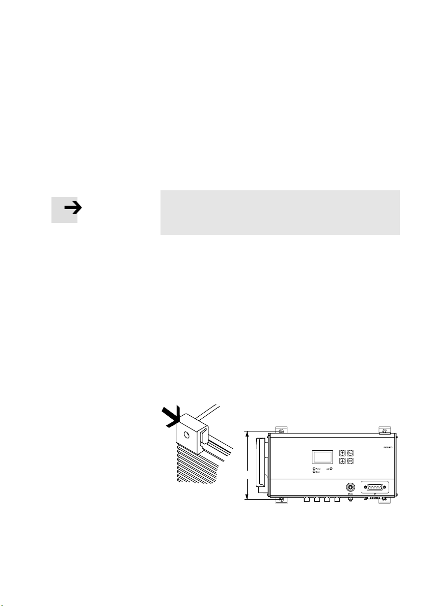
2.2 Dimensions of the controller
247 mm
120 mm
2−4
Fig.2/1: Dimensions of the controller
Festo GDCP−SFC−LACI−IO−EN en 0812N H
Page 41
2. Assembly
2.3 Mounting the controller
You can mount the SFC−LACI in one of two ways:
1. Wall mounting on a flat surface
2. H−rail mounting
Note
Mount the SFC−LACI or hat rail so that there is sufficient space
for heat dissipation (above and below at least 40 mm).
2.3.1 Wall mounting
You will need:
A mounting surface of approximately 250 x 320 mm
2 sets of central supports, type MUP−8/12 (accessories).
The four brackets are clipped into the edge of the housing
(see Fig.2/2).
Festo GDCP−SFC−LACI−IO−E N en 0812NH
4 tapped holes for screw size M3 with matching screws.
120 mm
Fig.2/2: Wall mounting
2−5
Page 42
2. Assembly
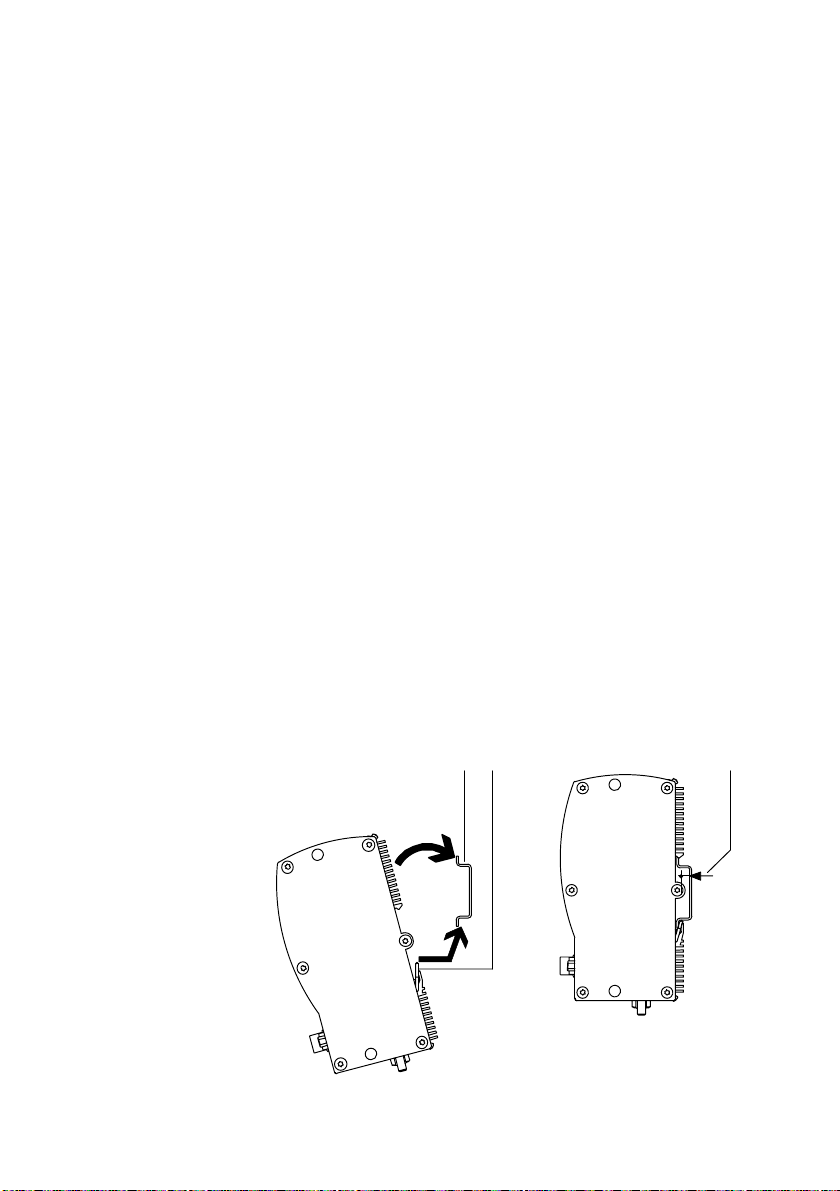
2.3.2 Hat−rail mounting
Procedure:
1. Make sure that the mounting surface can support the
weight (approx. 1500 g) of the SFC−LACI.
2. Install an H−rail (mounting rail EN 50022 35x7.5 or
better still 35x15).
3. With rail 35x7.5: Consider the max. distance of 3.3 mm
between the housing and the H−rail:
· If possible, use a part of the H−rail where there are no
mounting screws.
· If screws are necessary below the SFC−LACI:
use e.g. an M6 screw as per ISO−7380ULF.
4. Hang the SFC−LACI on the H−rail as follows:
1 H−rail
2 Tension springs
3 Distance between
housing web and
H−rail: 3.3 mm
(rail 35x7.5)
Fig.2/3: H−rail mounting
2−6
· first from below, pressing against the tension springs,
then
· press up against the H−rail so that the SFC−LACI clicks
into place.
12 3
Festo GDCP−SFC−LACI−IO−EN en 0812N H
Page 43

Installation
Chapter 3
3−1Festo GDCP−SFC−LACI−IO−E N en 0812NH
Page 44

3. Installation
Contents
3.1 Installation overview 3−3 . . . . . . . . . . . . . . . . . . . . . . . . . . . . . . . . . . . . . . . . . . . .
3.2 Power supply 3−6 . . .
3.2.1 Function of the
3.3 Earthing 3−10 . . . . . . . . . . . . . . . . . . . . .
3.4 Motor connection 3−11 . . . . . . . . . . . . . .
3.5 Parametrising interface 3−14 . . . . . . . . . . . . . . . .
3.6 Controller interface 3−16 . . . . . . . . . . . . . . . . . . . . . .
3.6.1 Specifications of the controller interface 3−18 . . . . . . . . . . . . . . . . . . . . .
3.7 Local
digital inputs and outputs 3−19 . . . . . . . . . . . . . . . . . . . . . . . . . . . . . . . . . . .
3.7.1 Specifications of the outputs 3−20 . . . . . . .
3.7.2 Specifications of the inputs 3−21 . . . . . . . . . . . . . . . . . . . . . . . .
. . . . . . . . . . . . . . . . . . . . . . . . . . . . . . . . . . . . . . . . . . . . . . .
hardware enable 3−9 . . . . . . . . . . . . . . . . . . . . . . . . . . .
. . . . . . . . . . . . . . . . . . . . . . . . . . . . . . . . . .
. . . . . . . . . . . . . . . . . . . . . . . . . . . . . . . . .
. . . . . . . . . . . . . . . . . . . . . . . . . .
. . . . . . . . . . . . . . . . . . . . . . . .
. . . . . . . . . . . . . . . . . . . . . . .
. . . . . . .
3−2
Festo GDCP−SFC−LACI−IO−EN en 0812N H
Page 45

3. Installation
3.1 Installation overview
Warning
Before carrying out fitting, installation and/or mainten
ance work, always switch off the power supply.
In this way, you can avoid:
uncontrolled movements of the connected actuators
undefined switching states of the electronic components
damage to the electronic components
Caution
Faulty pre−assembled lines may destroy the electronics
and trigger unexpected movements of the motor.
· For connecting the electric components of the system,
· Lay all flexible lines so that they are free of kinks and
use only the cables listed as accessories (see Tab.3/2).
free of mechanical stress; if necessary use chain link
trunking.
Festo GDCP−SFC−LACI−IO−E N en 0812NH
3−3
Page 46

3. Installation
1 Parametrising
interface (RS232)
2 Controller interface
3 Power supply
4 Earth terminal
5 Local digital I/Os
6 Motor connection
(e.g. DNCE−...−LAS)
6
Fig.3/1: Connections to the SFC−LACI
Connection to the SFC−LACI−IO
1 Parametrising
interface
2 Controller in
terface
3 Power supply Sub−D plug, 7WT Voltage connection with 2high−current contacts
M8 socket, 4−pin RS232 interface for parametrising, commissioning
Sub−D plug, 15−pin Interface for connecting to a PLC controller.
Description
and diagnosis via FCT. } Section 3.5
} Section 3.6
and 5low−current contacts (separate load and logic
voltage supply). } Section 3.2
45
1
2
3
4 Earth terminal Stud bolt, M4 Functional earth connection } Section 3.3
5 Local digital
I/Os
6 Motor
connection
M8 socket, 3−pin Local digital inputs and outputs
Plug connector,
type ITT Cm3
} Section 3.7
Power supply for linear motor and sensor signals
} Section 3.4
Tab.3/1: Overview of connections
3−4
Festo GDCP−SFC−LACI−IO−EN en 0812N H
Page 47
3. Installation
If unused plug connectors are touched, there is a danger that
damage may occur to the SFC−LACI or to other parts of the
system as a result of ESD (electrostatic discharge). Place pro
tective caps on unused terminal connections in order to pre
vent such discharges.
Overview of cables
Connection Cable Type
1 Parametrising interface Programming cable KDI−MC−M8−SUB−9−2.5
2 Controller interface Pilot line KES−MC−1−SUB−15−...
3 Power supply Power supply cable KPWR−MC−1−SUB−15HC−...
5 Local digital I/Os Connecting cable KM8−M8−... or NEBU−M8−...
6 Motor connection Motor cable NEBM−T1G6−T1G6−...
Encoder cable NEBM−T1G12−T1G12−...
Tab.3/2: Overview of cables (accessories)
For complying with the IP protection class:
· Tighten the union nuts/locking screws on the plugs by
hand.
· Seal unused M8 connections with type ISK−M8 protective
caps (accessories).
Observe the tightening torques specified in the
documentation for the cables and plugs used.
Festo GDCP−SFC−LACI−IO−E N en 0812NH
3−5
Page 48

3. Installation
3.2 Power supply
Warning
· Use only PELV circuits as per IEC/DIN EN 60204−1 for
the electric power supply (protective extra−low voltage,
PELV).
Take into account also the general requirements for
PELV circuits as per IEC/DIN EN60204−1.
· Use only power supply units that guarantee reliable
electrical isolation of the operating voltage as per
IEC/DIN EN 60204−1.
Protection against electric shock (protection against direct
and indirect contact) is guaranteed in accordance with
IEC/DIN EN 60204−1 by using PELV circuits (electrical equip
ment of machines, general requirements).
Note
Note that the tolerances of the voltage supply must also be
observed directly at the voltage supply connection of the
SFC−LACI.
· For the power supply, use only the cables specified in
Tab.3/2.
· Use closed−loop regulated power supply units that
comply with the requirements described in Tab.3/4.
3−6
Load voltage supply: The use of power supply units with
lower output levels is possible with restricted motion dy
namics and loads. To do this, you need to enter the power
output of your power supply unit into the
FCT (or via the CI
object 6510/50h).
Festo GDCP−SFC−LACI−IO−EN en 0812N H
Page 49

3. Installation
Connection Pin Designation Function Colour
A1 Load voltage +48 VDC load Black, 1
A2 Load voltage GND load Black, 2
1 Logic voltage +24 VDC logic White
2 Logic voltage GND logic Brown
3 Hardware
enable
4 FE FE
5 Hardware
enable
Plug housing FE
+24 VDC hard
ware enable
3)
GND hardware
enable
3)
Green
2)
Yellow
Earthing strap
with cable
lug M4
Earth
FE
3)
terminal
(housing)
1)
Wire colours of supply cable KPWR−MC−1−SUB−15HC−...
2)
With cable type KPWR−MC−1−SUB−15HC−... not connected.
3)
Use only one connection; see section 3.3
Tab.3/3: Power" connection (voltage supply) on the SFC−LACI
1)
Festo GDCP−SFC−LACI−IO−E N en 0812NH
Caution
Damage to the device
The load voltage supply input has no special protection
against overvoltage.
· Make sure the permissible voltage tolerance is never
exceeded; see Tab.3/4.
3−7
Page 50

3. Installation
Requirements to be met by the power supply
Voltage Use Currents
48 VDC
+5/−10%
24 VDC ±10% Logic supply (pins 1, 2) Nominal current (peak current): 0.4 A (0.8 A)
24 VDC ±10% Supply of the outputs of the con
Load supply (pins A1, A2) Nominal current (peak current): 10 A (20 A)
Local outputs OUT1/2 Supply via logic supply (pins 1, 2).
Hardw a re enable (pins 3, 5) Minimum current on contact for the load voltage.
Tot a l Dependent on the system architecture, up to 3.8 A.
troller interface
Connection and pin assignment:
see section 3.6.
Internal fuse: 16 A slow−blow (external as an option)
Internal fuse: 4 A slow−blow (external as an option)
Max. 1 A permissible per output.
Idle current: 0.05 A
Peak current (max. 0.5 A per output): 2.1 A
Tab.3/4: Requirements to be met by the power supply
Example of a power supply connection
Connect the
1
earth terminals
of the two power
supply units.
1 2 3 4A1 5 A2
2 External fuses
(as an option)
3 Switch for
hardware enable
4 Earth terminals
(only use one,
see section 3.3)
3−8
1 2 3 4
Fig.3/2: Power supply connection example
Festo GDCP−SFC−LACI−IO−EN en 0812N H
Page 51

3. Installation
3.2.1 Function of the hardware enable
Application of 24 VDC to pin 3 (relative to pin 5) of the power
supply connection is essential for operation of the SFC−LACI.
In a similar fashion to the relay, Hardware Enable" switches
the load voltage on and off, whereby the voltage of the
hardware enable represents the control voltage:
Hardware enable applied:
the load voltage is switched
through.
Hardware enable missing: the load voltage is blocked.
Switching the voltage on or off of the Hardware Enable" is
thus equivalent to switching the load voltage on or off.
The Hardware Enable is electrically isolated.
Use of the Hardware enable is described in section 5.5.4.
Festo GDCP−SFC−LACI−IO−E N en 0812NH
3−9
Page 52

3. Installation
3.3 Earthing
Note
· Connect one of the earth terminals of the SFC−LACI at
low impedance (short cable with large cross−section)
to the earth potential.
You can thereby avoid interference from electromagnetic
sources and ensure electromagnetic compatibility in
accordance with EMC directives.
To earth the SFC−LACI, use one of the following terminals
(see Tab.3/3):
Earth terminal on
the housing of the SFC−LACI, or
Earthing strip with cable lug on the plug housing.
Note
Note that only one of the three earth terminals may be
used (to avoid earth loops).
When using the earth terminal on the housing of the
SFC−LACI:
· Use a suitable earthing cable with an M4 cable lug to
gether with the accompanying nut and toothed washer.
· Tighten the nut with max. 1.7 Nm.
3−10
Festo GDCP−SFC−LACI−IO−EN en 0812N H
Page 53
3. Installation
2
3
3
4
1
2
3
4
1
2
3.4 Motor connection
The linear motor is controlled via the motor connection and
the signals from the displacement encoder are transmitted
via the motor connection.
Pin
Colour Function Plug on the SFC−LACI
1 White Motor: String U
2 Brown Motor: String V
3 Green Motor: String W
4
1 Yellow Motor: String U/
2 Grey Motor: String V/
3 Pink Motor: String W/
4 Black plug, B
1 Blue VCC +5 V DC
2 Red GND
3 White Temperature sensor
4 Brown Temperature sensor GND
5 orange Reference switch +24 V DC Yellow plug
6 Grey Reference switch input
1 Green Data serial +
2 Yellow Data serial
3 Black GND
4 Brown VCC +5V DC
3
4
Black plug, A
4
6
4
2
(sensors)
6
4
2
2
1
1
5
1
5
1
5 Red Pulse Red plug
6 orange Pulse +
(BiSS position measuring
system)
Tab.3/5: Motor connection to the SFC−LACI
Festo GDCP−SFC−LACI−IO−E N en 0812NH
3−11
Page 54

3. Installation
Displacement encoder for BiSS interface
The BiSS interface is a 2−wire interface for interference−im
mune sensor connection. In contrast to the SSI interface, the
data transmission is bi−directional, which means, for example,
that data can also be written into the sensor for parametrisa
tion.
Data is transmitted via a pulse cable controlled by the master
and a data cable
mission. Data is written to the slave via the cycle’s pulse
width modulation in accordance with the "BiSS B mode" pro
tocol specification http://www.biss−ic.de/files/
BiSS_b3ds.pdf; the direc¬tion of the data cable is not
switched. Pulse and data are transmitted using RS485 tech
nology, which means a
inverted and issued at the receiver as differential input. This
suppresses common−mode interference. The data are also
secured by a CRC code.
The BiSS interface supports 2 read−out modes:
controlled by the sensor as serial trans
signal is sent not−inverted as well as
3−12
The sensor data channel for fast pulse out (pulse up to 10
MHz) of the sensor information
The
parameter channel for reading and writing sensor
parameters as well as for depositing user−specific data
protected against zero voltage in the sensor’s EEPROM
The distinction is made on the basis of the start bit, details
can be referred to in the specifications given.
Festo GDCP−SFC−LACI−IO−EN en 0812N H
Page 55

3. Installation
Fig.3/3: Sensor data communication
Bits Type Label
[19:30] DATA Cycle counter 12 bit (multiturn position)
[8:18] DATA Angle data 11 bit (singleturn position)
[7] Error Error bit E1 (amplitude error)
[6] Error Error bit E0 (frequency error)
[0:5] CRC Polynomial 0x43; x6+x1+x0 (inverted bit output)
Tab.3/6: BiSS Interface
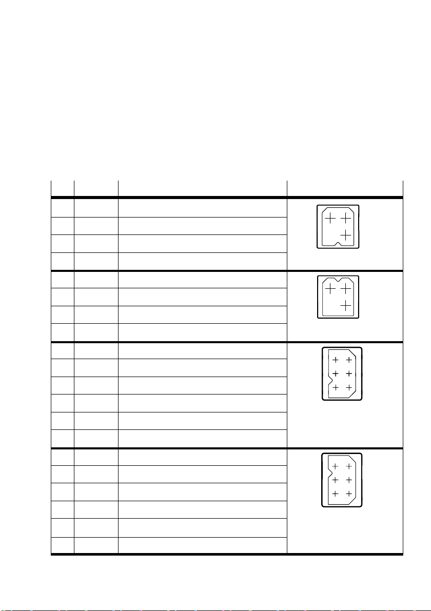
Festo GDCP−SFC−LACI−IO−E N en 0812NH
3−13
Page 56

3. Installation
3.5 Parametrising interface
Serial interface for parametrizing, commissioning and diag
nosing.
Note
For connecting a PC to the SFC−LACI, use only the cable
specified in Tab.3/2.
· If necessary, remove the protective cap from the parame
trising interface.
· Connect the following terminals with the programming
cable:
the socket on the SFC−LACI
a serial interface COMx of the PC.
3−14
M8 socket
1243
1)
The levels correspond to the RS232 standard.
Description
1 GND Ground
2 RXD RS232 1): Receiving cable of PC,
transmitting cable of SFC−LACI
3 TXD RS232 1) Transmitting cable of PC,
receiving cable of SFC−LACI
4 (reserved, do not use)
Tab.3/7: Parametrising interface (RS232) of the SFC−LACI
Festo GDCP−SFC−LACI−IO−EN en 0812N H
Page 57

3. Installation
Information on commissioning and parameterising the
SFC−LACI via the parametrising interface can be found in
chapter 5.3.2 and in the help system for the Festo
Configuration Tool software package.
Information on transmitting CI commands via the
parametrising interface can be found in Appendix B.
Note
The parametrising interface (RS232) is not electrically
isolated and is not real−time capable. It is not suitable for
permanent connection to PC systems, or as a control inter
face.
· Use this terminal only for commissioning.
· Remove the programming cable in continuous
operation.
· Seal the terminal with the protective cap supplied
(type ISK−M8).
Festo GDCP−SFC−LACI−IO−E N en 0812NH
3−15
Page 58

3. Installation
3.6 Controller interface
Communication with the higher−order controller (PLC/IPC)
occurs via the controller interface.
Information on controlling the SFC−LACI via the controller
interface can be found in section 5.5.
Caution
If 24 V DC voltage is applied and the output pins are used
incorrectly, the device may be seriously damaged. There
fore:
· Do not apply voltage to the outputs.
· Note the current limitation for the outputs
(see section 3.6.1).
3−16
Note
The I/O power supply 24VDC_EXT is essential for
operating the outputs O1 ... O4.
· Connect +24 VDC to pin 1 and 0 V to pin 8 or pin 15.
· Take into account the overview in Tab.3/4.
· Use only the PELV power supply units (see section 3.2).
Festo GDCP−SFC−LACI−IO−EN en 0812N H
Page 59

3. Installation
Connection to the
SFC−LACI
18
9
Pin Designation Function Cable colour
1 24VDC_EXT Electrically isolated I/O
White
1)
supply (infeed)
15
2 I1 Input for positioning record
coding bit 0
3 I2 Input for positioning record
Brown
Green
coding bit 1
4 I3 Input for positioning record
Yellow
coding bit 2
5 I4 Input for positioning record
Grey
coding bit 3
6 I5 Input for positioning record
Pink
coding bit 4
7 I6 STOP input Blue
8 GND−EXT
2)
Electrically isolated GND
Red
(reference potential) for I/O
9 I7 ENABLE input Black
10 I8 START input Purple
11 O1 MC output Grey−pink
12 O2 READY output Red−blue
13 O3 ACK output White−green
14 O4 E RROR output Brown−green
15 GND−EXT
2)
Electrically isolated GND
(reference potential) for I/O
FE Functional earthing (Plug housing /
1)
Cable colours with pilot line type KES−MC−1−SUB−15−...
2)
Alternative
Tab.3/8: I/F" terminal (controller interface) on the SFC−LACI−...−IO
Festo GDCP−SFC−LACI−IO−E N en 0812NH
White−yellow
cable screening)
3−17
Page 60

3. Installation
3.6.1 Specifications of the controller interface
I/O specification
Signal level Based on DIN EN 61131, type 1,
Inputs
Number of digital logic inputs 8
Input current at 24 V input
voltage
Max. permissible input
voltage
Minimum input voltage 0 V DC
Reverse polarity protection Yes
Galvanic isolation Yes
Outputs
Number of digital logic outputs 4
Maximum peak current 0.5 A per output
Overload protection Yes.
positive switching (PNP)
Typically > 7 mA
30 V DC
Reversed−polarity voltage must
not be applied!
Tab.3/9: I/O specification
3−18
Festo GDCP−SFC−LACI−IO−EN en 0812N H
Page 61

3. Installation
3.7 Local digital inputs and outputs
Out1 Out2 In1 In2
341
Connection Pin Function
Output 1
(Out1)
Output 2
(Out2)
Input 1
(In1)
Input 2
(In2)
3 Ground (GND)
4 Signal
1 +24 VDC logic voltage output
3 Ground (GND)
4 Signal A
1 Signal /A
3 Ground (GND)
4 Proximity sensor contact
1 +24 VDC voltage output for proximity sensor
3 Ground (GND)
4 Proximity sensor contact
1 +24 VDC voltage output for proximity sensor
341 341
341
Festo GDCP−SFC−LACI−IO−E N en 0812NH
3−19
Page 62

3. Installation
3.7.1 Specifications of the outputs
The local digital outputs are supplied by the 24−V logic
voltage (no electrical isolation). They are ESD protected and
short circuit proof, but do not have reverse polarity protec
tion against infeed.
Caution
If 24 V DC voltage is applied and the output pins are used
incorrectly, the device may be seriously damaged. There
fore:
· Do not apply voltage to the outputs.
· Note the current limitation for the outputs
(max. 1 A permissible per output).
Special features of output 1 (Out1)
Standard PLC output (active high−side switching)
3−20
Special features of output 2 (Out2)
Differential output (can be pulse−width modulated)
High− und low−side switching (active full bridge)
It is not used for controlling a PLC, but rather for control
ling a load, e.g. to control a pulsed motor brake, a valve
or a fan.
The possible uses dependent on the selected pins are de
scribed in section 5.5.5.
Festo GDCP−SFC−LACI−IO−EN en 0812N H
Page 63
3. Installation
3.7.2 Specifications of the inputs
Based on DIN/EN 61131, Part 2 (IEC 1131−2), Type 1
They are supplied by 24 V logic voltage (no electrical
isolation)
Note
Damage to the device
The 24 V DC voltage at pin 1 does not have any special
protection against overload.
· Use this connection only for proximity sensors (sensor
supply).
Use of this connection as a power supply for other devices
is not permitted.
· For connecting the proximity sensor, use a cable with
rotating thread sleeve (union nut) on the end of the cable,
e.g. an extension cable type KM8−M8−... or NEBU−M8−...
Festo GDCP−SFC−LACI−IO−E N en 0812NH
· When selecting the proximity sensor, note that the accu
racy of the proximity sensor switching point may affect
the accuracy of the reference point.
· During installation, note the position of the reference
switch relative to the index pulse. If necessary, move
the reference switch (see I NDEX PULSE WARNING",
section 6.3).
3−21
Page 64

3. Installation
3−22
Festo GDCP−SFC−LACI−IO−EN en 0812N H
Page 65

The control panel (only type SFC−LACI−...−H2)
Chapter 4
4−1Festo GDCP−SFC−LACI−IO−EN en 0812NH
Page 66

4. The control panel (only type SFC−LACI−...−H2)
Contents
4.1 Design and function of the control panel 4−4 . . . . . . . . . . . . . . . . . . . . . . . . . . . .
4.2 The menu system 4−6 . . . . . . . . . . . . .
4.3 [Diagnostic] menu 4−8 . . . . . . . . . . . . . .
4.4 [Positioning] menu 4−10 . . . . . . . . . . . . . . . . .
4.5 Menu [Settings] 4−12 . . . . . . . . . . . . . . . . . . .
4.5.1 [Settings] [Axis type] 4−13 . . . . . . . . . . . . . . . . . . .
4.5.2 [Settings] [Axis parameters] 4−13 . . . . . . . . . . . . . . . . . . . . . . . . . . . . .
4.5.3 [Settings] [Homing parameters] 4−14 . . . . . . . . . . . . . . . . . . . . . . . . . . . .
4.5.4 [Settings] [Position set] 4−15 . . . . . . . . . . . . . . .
4.5.5 [Settings] [Jog Mode] 4−16 . . . . . . . . . . . . . . . . . . . . . . . . . . .
4.5.6 [Settings] [Password edit] 4−16 . . . . . . . . . . . . . . . . . . . . . . . . . . . . . . . . .
4.6 Menu command HMI control" 4−18 .
. . . . . . . . . . . . . . . . . . . . . . . . . . . . . . . . . .
. . . . . . . . . . . . . . . . . . . . . . . . . . . . . . . .
. . . . . . . . . . . . . . . . . . . . . . . . . . . . .
. . . . . . . . . . . . . . . . . . . . . . . . . . . . .
. . . . . . . . . . . . . . . . . .
. . . . . . . . . . . . . . . . . . . .
. . . . . . . . . .
. . . . . . . . . . . . . . . . . . . . . . . . . . . . . . . . . . .
. .
4−2
Festo GDCP−SFC−LACI−IO−EN en 0812N H
Page 67

4. The control panel (only type SFC−LACI−...−H2)
The control panel of the SFC−LACI−...−H2 provides many
functions for commissioning, parametrisation and diagnos
tics. An overview of the key and menu functions can be
found in this chapter.
Commissioning with the control panel is described starting
from section 5.2.
With the SFC−LACI−...−H0 (without control panel), you can
commission the device via the
the Festo Configuration Tool (FCT). Instructions on this can be
found in section 5.3.2.
Caution
Simultaneous or alternating attempts to access the
SFC−LACI via FCT, control panel and controller interface
can cause unpredictable errors.
· Make sure that the FCT, the control panel and the con
troller interface of the SFC−LACI are not used at the same
time.
parametrising interface using
Festo GDCP−SFC−LACI−IO−E N en 0812NH
4−3
Page 68

4. The control panel (only type SFC−LACI−...−H2)
4.1 Design and function of the control panel
The control panel allows:
Parametrising and referencing the drive (homing
methods: to the stop and to the integrated reference
switch of the drive)
Teaching and editing the positioning records
Execution/testing of positioning records
1 LC display
2 Operating
buttons
3 LEDs
Power (green)
I/F (green/red)
Error (red)
Fig.4/1: Control panel of the SFC−LACI−...−H2
LC display The graphic LCD shows all text in English. The display can be
rotated 180°; see [LCD adjustment] menu command.
LEDs Display of operating states (see chapter 6.2):
Power: Power supply
I/F: Communication via the controller interface
Error: Error message or warning
1
2
3
4−4
Festo GDCP−SFC−LACI−IO−EN en 0812N H
Page 69

4. The control panel (only type SFC−LACI−...−H2)
Operator keys Basic functions of the operator keys:
Key Function
Menu
MENU Activates the main menu from the status
display.
ESC Rejects the current input and returns in
steps to the higher−order menu level or
status display.
EMERG.STOP If [HMI = on]: interrupts the current posi
tioning procedure (> Error mode; con
firm with <Enter>, then automatic return
to the status display).
Enter
OK Confirms the current selection or input.
SAVE Saves parameter settings permanently in
the EEPROM.
START/STOP Starts or stops a positioning procedure
(only in Demo mode). After stop: Display
of current position; use <Menu> to return
to the higher−order menu level.
v
V
{ } Scrolls within a menu level in order to
select a menu command.
EDIT Sets parameters.
Tab.4/1: Key functions (overview)
Festo GDCP−SFC−LACI−IO−E N en 0812NH
4−5
Page 70

4. The control panel (only type SFC−LACI−...−H2)
4.2 The menu system
Status display and main menu
When the logic voltage is switched on, the SFC−LACI carries
out an internal check. The display briefly shows the Festo
logo then changes to the status display.
SFC–LACI...
D...
Xa = 0.00 mm
HMI:off
<Menu>
} Diagnostic
Positioning
Settings
V ESC <Menu>
<––> OK <Enter>
} HMI control
LCD adjustment
v ESC <Menu>
<––> OK <Enter>
The status display shows the following information:
the type designation of the SFC−LACI
the type of connected drive
the position of the drive x
= .... (still without significance
a
when unit is switched on)
the current setting of the device control
(HMI = Human Machine Interface)
The main menu is accessed from the status display using the
<Menu> key. The currently active key function is displayed in
the lower lines of the LCD display.
4−6
Festo GDCP−SFC−LACI−IO−EN en 0812N H
Page 71

4. The control panel (only type SFC−LACI−...−H2)
} p
} gp
}
Menu command Description
} Diagnostic Displays the system data and the settings currently in effect (} 4.3)
} Pos. set table Displays the position set table
} A xis parameters Displays axis parameters and data
} System paramet. Displays system parameters and data
} SW information Displays the operating system version (firmware)
} Positioning Homing and positioning runs (} 4.4)
} Homing Start the reference run
} Move posit. set Star t an individual positioning record
} Demo posit. tab Star ts the Demo mode"
} Settings Parametrisation (} 4.5)
} Axis type } not adjustable The type of the drive is automatically detected
} Axis parameter } Zero point Offset of the axis zero point relative to the reference point
} SW−limit−neg Software end position, negative; offset relative to the axis zero point
} SW−limit−pos Software end position, positive; offset relative to the axis zero point
} Tool load Tool load mass (e.g. gripper on front plate/piston rod)
} SAVE... Saves parameters to the EEPROM
} Homing paramet. } Homing method Reference travel (homing) method
} Velocity v_rp Speed when searching for the reference point
} Velocity v_zp Speed when moving to the axis zero point
} SAVE... Saves parameters to the EEPROM
} Position set } Position nr Number of the positioning record (1...31)
} Pos set mode Absolute or relative positioning; if necessary, energy optimised
} Position Target position
} Velocity Speed
} Acceleration Acceleration
} Deceleration Deceleration (Braking)
} Jerk Acc. Acceleration jerk
} Jerk Dec. Deceleration jerk
} Work load Applied load (= workpiece mass)
} Time MC Damping time
} SAVE... Saves parameters to the EEPROM
} Jog mode Move the drive using the arrow buttons
} Password edit Set up a local password for the control panel (} 4.5)
} HMI control Preset the device control via the control panel(} 4.6)
} LCD adjustment Rotate the display 180°
Tab.4/2: Menu commands (overview)
Festo GDCP−SFC−LACI−IO−E N en 0812NH
4−7
Page 72

4. The control panel (only type SFC−LACI−...−H2)
4.3 [Diagnostic] menu
In order to display the system data and the currently effective
settings:
} Diagnostic
Pos.set table
Axis parameter
System paramet.
SW information
1. Select the [Diagnostic] menu in the main menu.
<ENTER>
2. Select a menu command. <ENTER>
{ } You can scroll through the data with the arrow
keys.
ESC You can use the <Menu> key to return to the
higher−order menu.
[Diagnostic] [...]
[Pos. set table] No. Number of the positioning record
Description
a/r (e) Absolute (a) or relative (r) positioning,
Pos Target position
Vel Speed
*)
acc
*)
dec
Work load
Yes
jd
t_MC
*)
*)
*)
*)
(e) = energy optimised
Acceleration
Deceleration (Braking)
Applied load ( = mass of the workpiece)
Acceleration jerk
Deceleration jerk
Damping time
4−8
*) After 5 s the lower part of the display changes.
Festo GDCP−SFC−LACI−IO−EN en 0812N H
Page 73

4. The control panel (only type SFC−LACI−...−H2)
[Diagnostic] [...] Description
[Axis parameter] v max Maximum speed
x neg Stroke limitation: Software end position, negative
x pos Stroke limitation: Software end position, positive
x zp Offset axis zero point
Tool load Tool load (e.g. a gripper on the front plate or on the
[System paramet.] Load Power Load voltage ok?
VDig Digital voltage (= Logic voltage) [V]
I max Max. phase current [A]
P_Pos Average power during last positioning procedure [W]
t_Pos Time taken for the last positioning procedure [s]
Cycle Number of positioning movements
Mode Unit of measurement [mm]
Hom.meth. The parametrised homing method:
Ref. switch Activated (switching) position of the parametrised refer
Neg. Lim−Sw Activated (switching) position of the negative limit switch
Pos. Lim−Sw Activated (switching) position of the positive limit switch
T_Motor Temperature of the linear motor [°C]
piston rod)
RefS.n: Reference switch in negative direction
RefS.p: Reference switch in positive direction
Bl.pos: Fixed stop in positive direction
Bl.neg: Fixed stop in negative direction
LimS.p: Limit switch in positive direction
LimS.n: Limit switch in negative direction
ence switch
T_LACI Temperature of the SFC−LACI [°C]
[SW information] SFC−LACI firmware version
Tab.4/3: [Diagnostic] menu
Festo GDCP−SFC−LACI−IO−E N en 0812NH
4−9
Page 74
4. The control panel (only type SFC−LACI−...−H2)
4.4 [Positioning] menu
Starting a homing run or a positioning run
Warning
Electric axes move with high force and at high speed.
Collisions may cause injury.
· Make sure that nobody can place his/her hand in the
positioning range of the moveable mass and that there
are no objects in its path.
Note
· Before starting the reference run, make sure that:
The positioning system is set up and wired
completely, and is supplied with power.
The parametrising is completed.
· Only start a positioning run after:
The reference system has been defined by a refer
ence run.
You have checked that the software end positions are
far enough away from the mechanical end positions/
fixed stops (at least 1 mm).
4−10
Note
Please note that positioning records with speed v = 0 or
invalid target positions ( −> error TARGET POSITION OUT
OF LIMIT) cannot be executed.
Festo GDCP−SFC−LACI−IO−EN en 0812N H
Page 75

4. The control panel (only type SFC−LACI−...−H2)
} Positioning
Homing
Move posit. set
Demo posit. tab
The Positioning" menu includes entries for starting a homing
run or a positioning run.
Note
Carry out the homing run and the positioning runs as de
scribed in the following sections:
Homing: sections 5.2.1 to 5.2.3
Positioning runs / test runs: section 5.2.8
[Positioning]
[Homing] Starting a homing run with the set hom
[Move posit.
set]
[Demo posit.
tab]
Description Note
ing method
Starting a defined positioning record
from the position set table
Test of all positioning records in the
position set table (operating mode
Demo mode")
Tab.4/4: [Positioning] menu
Setting the parameters: see
[Settings] [Homing parameters]
Parametrising and referencing must
have been completed.
Parametrising and referencing must
have been completed.
There must be at least two positioning
records in the memory.
Festo GDCP−SFC−LACI−IO−E N en 0812NH
Cancelling a positioning movement
EMERG.
STOP
DEMO
STOP
You use <Menu> to interrupt a positioning task
(> Error mode EMERG.STOP).
With <Enter>, you can interrupt the Demo
mode" [Demo posit tab]. The current position
ing record will be executed before the axis
stops. If you restart, the run will begin with
positioning record 1.
Menu
Enter
4−11
Page 76
4. The control panel (only type SFC−LACI−...−H2)
4.5 Menu [Settings]
For parametrising the axis system and the positioning
records:
} Settings
Axis type
Axis parameter
Homing paramet.
Position set
Jog mode
Password edit
[Settings]
[Axis type] The axis controlled by the SFC−LACI 4.5.1
[Axis parameter] Teach mode for setting the axis parameters 4.5.2
[Homing paramet.] Setting the homing travel method and the speed during homing
[Position set] Teach mode for programming the position record table 4.5.4
[Jog mode] Jog mode: Moving by means of the arrow keys 4.5.5
[Password edit] Setting up a password for the control panel 4.5.6
Description Section
travel
1. Select the entry [Settings] in the main menu. <ENTER>
2. Select a menu command. <ENTER>
4.5.3
Tab.4/5: [Settings] menu
Note
The set parameters take effect immediately after confirma
tion with OK <ENTER>.
· Use [SAVE...] to permanently save the settings in EE
PROM. Only then will the settings be retained even after
switching off the power supply or in the event of a power
failure.
4−12
Festo GDCP−SFC−LACI−IO−EN en 0812N H
Page 77
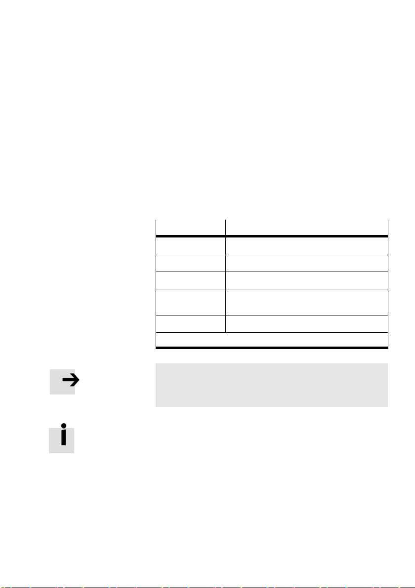
4. The control panel (only type SFC−LACI−...−H2)
4.5.1 [Settings] [Axis type]
The connected drive is automatically detected.
4.5.2 [Settings] [Axis parameters]
Teach mode for setting the axis parameters
· Observe the instructions in sections 5.2.4 and 5.2.5.
[Axis parameter]
[Zero point]
[SW−limit−neg]
[SW−limit−pos]
[Tool load] Tool mass, e.g. a gripper on the front plate/
[SAVE...] Save parameters in EEPROM
*)
Teaching is only possible after a successful homing run.
*)
Description
Offset axis zero point
*)
Software end position, negative
*)
Software end position, positive
piston rod
Note
A new homing run must always be carried out after
modifying the axis zero point.
The project zero point PZ can only be set via FCT or CI
object21F4
.
h
Festo GDCP−SFC−LACI−IO−E N en 0812NH
4−13
Page 78
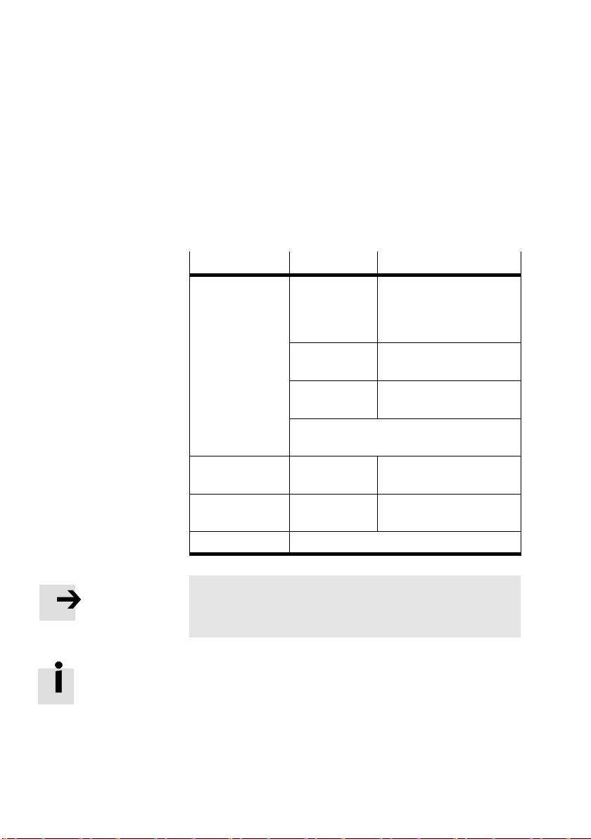
4. The control panel (only type SFC−LACI−...−H2)
4.5.3 [Settings] [Homing parameters]
Setting the homing method and the speed during reference
travel.
· Observe the instructions in chapter 5.2.1.
[Hom. paramet.]
[Homing method] switch negative Homing to the integrated
[Velocity v_rp] v_rp Speed when searching for
[Velocity v_zp] v_zp Speed when moving to the
[SAVE...] Save parameters in EEPROM
Param. Description
reference switch at the
retracted end position with
index search
block negative Homing to a negative fixed
stop
block positive Homing to positive fixed
stop
Note: Further homing run methods can only be
configured via FCT.
the reference point
axis zero point
Note
A new homing run must always be carried out after modify
ing the homing run method.
The maximum speed for homing is subject to built−in limits.
4−14
Festo GDCP−SFC−LACI−IO−EN en 0812N H
Page 79

4. The control panel (only type SFC−LACI−...−H2)
4.5.4 [Settings] [Position set]
Parametrising the position set table
· Observe the instructions in section 5.2.7.
· Select first the number of the desired positioning record.
The following settings refer to the currently selected posi
tioning record.
[Position set]
[Position nr] No. Number of the positioning record [1...31]
[Pos set mode] [absolute/
[Position]
[Velocity] vel Positioning speed in [mm/s]
[Acceleration] a Acceleration in [mm/s2]
[Deceleration] d Deceleration in [mm/s2]
[Jerk Acc] Yes Acceleration jerk in [m/s3]
[Jerk Dec] jd Deceleration jerk in [m/s3]
[Work load] m Applied load (= workpiece mass) in [g]
Time MC t_MC Damping time (time between reaching the target window and
[SAVE...] Saves parameters to the EEPROM
*)
*)
Teaching is only possible after a successful homing run.
Param. Description
relative]
xt Target position in [mm]
Positioning mode
absolute = Position specification refers to the project zero point
relative = Position specification refers to the current position
e = energy−optimized path generator
setting Motion Complete")
Festo GDCP−SFC−LACI−IO−E N en 0812NH
4−15
Page 80

4. The control panel (only type SFC−LACI−...−H2)
4.5.5 [Settings] [Jog Mode]
You can use the arrow keys to move the drive continuously
(also possible without previous reference run). The software
end positions have no effect here.
4.5.6 [Settings] [Password edit]
Access via the control panel can be protected by a (local)
password in order to prevent unauthorized or unintentional
overwriting or modification of parameters in the device. No
password has been preset at the factory (presetting = 000).
· Keep the password for the SFC−LACI in a suitable place,
e.g. in the internal documentation for your system.
If the active password in the SFC−LACI is lost:
The password can be deleted by entering a master password.
In this case please contact your Festo service partner.
New Password:
[ ? x x ] = 0
EDIT <––> SAVE <Enter>
ESC <Menu>
4−16
Setting a password
Select [Password edit] in the
menu [Settings]:
Enter a password with 3 digits. The current input position is
marked with a question mark.
1. Use the arrow keys to select a digit 0...9.
2. Confirm your input with <Enter>. The next entry position
will be displayed.
3. After entering the thirddigit, save your setting with SAVE
<Enter>.
Festo GDCP−SFC−LACI−IO−EN en 0812N H
Page 81

4. The control panel (only type SFC−LACI−...−H2)
Entering a password
Enter Password:
[ ? x x ] = 0
EDIT <––> OK <Enter>
ESC <Menu>
As soon as a password is active, it will be scanned automati
cally when the menu commands [Positioning], [Settings] or
[HMI control] are accessed.
1. Use the arrow keys to select a digit 0...9.
2. Confirm your input with <Enter>. The next entry position
will be displayed.
3. Repeat the entry for the remaining
When the correct password is entered, all parametrising and
control functions of the control panel are enabled until the
power supply is switched off.
Changing/deactivating the password
If the password has not yet been entered since the unit was
switched on:
entry positions.
Enter Password:
[ ? x x ] = 0
EDIT <––> OK <Enter>
New Password:
[ ? x x ] = 0
EDIT <––> SAVE <Enter>
Festo GDCP−SFC−LACI−IO−E N en 0812NH
ESC <Menu>
ESC <Menu>
· Select the menu item [Settings] [Password edit] and enter
the existing 3 digit password:
1. Use the arrow keys to select a digit 0...9.
2. Confirm your entry with OK <Enter>. The next entry
position will be displayed.
3. Repeat the entry for the remaining entry positions.
If the password has already been entered since the
unit was
switched on:
4. Enter the new password with 3 digits. If you wish to
deactivate the password, enter 000".
5. After entering the last digit, save your setting with SAVE
<Enter>.
4−17
Page 82
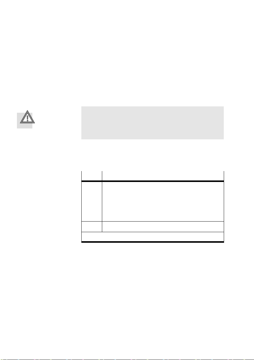
4. The control panel (only type SFC−LACI−...−H2)
4.6 Menu command HMI control"
To select the menu commands [Positioning] and [Settings],
the HMI: on" setting is required. Only then is the SFC−LACI
ready to process user entries on the control panel.
Caution
When control via the control panel or FCT is activated
(HMI:on), the drive cannot be stopped with the STOP
input on the control interface.
When selecting the menu commands, you will be prompted to
modify the HMI setting as necessary. You can also modify the
setting directly with the menu command [HMI control].
HMI 1)Device control
4−18
on The parametrising interface is activated. Operation
off Device control is done via the control interface.
1)
Human Machine Interface
and parametrisation can be performed manually via
the control panel or via FCT.
The control interface is deactivated. The status of all
the inputs then has no effect. The state of the outputs
is unimportant.
Festo GDCP−SFC−LACI−IO−EN en 0812N H
Page 83

Commissioning
Chapter 5
5−1Festo GDCP−SFC−LACI−IO−E N en 0812NH
Page 84

5. Commissioning
Contents
5.1 Preparations for commissioning 5−3 . . . . . . . . . . . . . . . . . . . . . . . . . . . . . . . . . . .
5.1.1 Checking the drive 5−4 . . . . . . . . . .
5.1.2 Checking the power supply 5−4 . . . . . . . . . . . . . . . . .
5.1.3 Before switching on 5−5 . . . . . . . . . . . . . . . . . . . . . . . . . . . . . . . . .
5.1.4 Simultaneous attempts to access the controller 5−6 . . . . . . . . . . . . . . .
5.2 Commissioning with the control panel (only type SFC−LACI−...−H2) 5−7 . . . . . . . .
5.2.1 Setting the reference run parameters 5−8 . . .
5.2.2 Activate device control 5−10 . . . . . . . . . . . . . . . . . . . . . . . . . . . .
5.2.3 Carry out a reference run 5−11 . . . . . . . . . . . . . . . . . . . . . . . . . . . . . . . . .
5.2.4 Teach the axis zero point 5−13
5.2.5 Teaching the software end positions 5−15 . . . . . . . . . . . .
5.2.6 Setting the tool mass 5−16 . . . . . . . . . . . . . . . . . . . . . . . . . . . . . . . . . .
5.2.7 Teaching positioning records 5−17 . . . . . . . . . . . . . . . . . . . . . . . . . . . . . .
5.2.8 Test run 5−19 . . . . . . . . . . . . . .
5.3 Commissioning with FCT 5−20 . . . . . . . . . . . . . .
5.3.1 Installing the FCT 5−21 . . . . . . . . . . . . . . . . . . . . .
5.3.2 Procedure 5−22 . . . . . . . . . . . . . . . . . . . . . . . . . . . . . .
5.4 Functional test 5−24 . . . . . . . . . . . . . . . . . . . . . . . . . . . . . . . . . .
5.5 Communication with the higher−order controller 5−25 . . . . . . . . . . . . . . . . . . . . . .
5.5.1 Description of the I/Os 5−26 . . . .
5.5.2 Functions (pulse−time diagrams) 5−33 . . . . . . . . . . . . . . . . .
5.5.3 Switching to next record 5−41 . . . . . . . . . . . . . . . . . . . . . . . . . . . . . . . . . .
5.5.4 Using hardware
5.5.5 Using the local digital outputs 5−43 . . . . . . . . . .
5.5.6 Using a brake/clamping unit 5−50 . . . . . . . . . . . . . . . . . . . . . . . . . . .
5.5.7 Position sampling (on−the−fly measurement) 5−53 . . . . . . . . . . . . . . . . . .
5.6 Notes on operation 5−55 . . . . . . . . . . . . . . . . . . . . . . .
enable 5−42 . . . . . . . . . . . . . . . . . . . . . . . . . . . . . . . . . . .
. . . . . . . . . . . . . . . . . . . . . . . . . . . . .
. . . . . . . . . . . . . . .
. . . . .
. . . . . . . . . . . . . . . . . . . .
. . . . . . .
. . . . . . . . . . . . . . . . . . . . . . . . . . . . . . . . . .
. . . . . . . . . . . .
. . . . . . . . . . . . . . . . . . . . . . . . . . . . . . . . .
. . . . . . . . . . . . . . . . . . . . . . . . . . .
. . . . . . . . . . . . . . . . . . .
. . . . . . . . . . . . . . .
. . . . . . . . . . . . . . .
. . . . . . . . . . . . . . . . . . . . . . . . . . . . . . .
. . . . . . . . . .
. . . . . . . . . . . . . . . . . . .
. . .
. . . . . . . . . . . . . . . . . . . . . . .
. .
5−2
Festo GDCP−SFC−LACI−IO−EN en 0812N H
Page 85

5. Commissioning
5.1 Preparations for commissioning
Warning
There is a danger of injury.
Electric axes can move suddenly with high force and at
high speed. Collisions can lead to serious injury to human
beings and damage to components.
· Make sure that nobody can reach into the operating
range of the axes or other connected actuators (e.g.
with a protective grille) and that no objects lie in the
positioning range while the system is still connected
to a power supply.
For commissioning, the mechanical system must be confi
gured and a measuring
(see Tab.1/1). By means of the measuring reference system,
all positions are defined and movement can be made to
them, e.g. with a positioning record from the position set
table.
reference system must be defined
Festo GDCP−SFC−LACI−IO−E N en 0812NH
· Carry out parametrising and commissioning by means of
the control panel or FCT, as described in the following
chapters and in the FCT/PlugIn help.
· Check the default settings in the [Diagnostic] menu.
· Upon completion of commissioning, note the instructions
for operation in the FCT/PlugIn help and in section 5.6.
5−3
Page 86

5. Commissioning
5.1.1 Checking the drive
Note
During operation, the drive must not strike a stop without
shock absorption.
· Use shock absorbers or buffers on all stops
(exception: homing to a fixed stop).
· Before commissioning, make sure that drive and
controller are completely set up and wired and that the
working space is adequate for operation with an effective
load.
· Observe the notes in the operating instructions for the
axis used.
5.1.2 Checking the power supply
5−4
Caution
Interruption of running tasks due to inadequate load volt
age supply (LOAD POWER DOWN")
· Make sure that the load voltage supply tolerance can be
maintained at full load directly on the voltage terminal of
the SFC−LACI (see chapter 3.2).
Caution
Loss of reference position due to inadequate logic supply
voltage
· Always carry out a reference run every time the logic
voltage supply is switched on, in order to anchor the
measuring reference system to the reference point
(REF).
The SFC−LACI does not carry out any positioning tasks if it
is not referenced.
Festo GDCP−SFC−LACI−IO−EN en 0812N H
Page 87

5. Commissioning
5.1.3 Before switching on
When the SFC−LACI is switched on, the controller interface is
activated as standard [HMI= off ].
Caution
Unexpected movements of the drive due to incorrect or
incomplete parametrising
· Make sure that there is no active ENABLE signal on the
· Parametrise the entire system completely before
controller interface when switching on the SFC−LACI.
activating the controller with ENABLE or [HMI = on].
Festo GDCP−SFC−LACI−IO−E N en 0812NH
5−5
Page 88
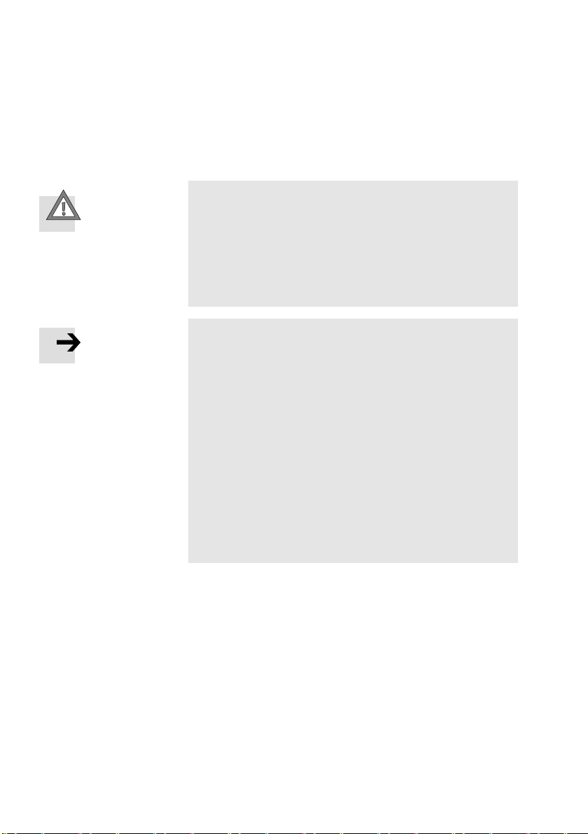
5. Commissioning
5.1.4 Simultaneous attempts to access the controller
Caution
Simultaneous or alternating attempts to access the
SFC−LACI via FCT, control panel and controller interface
can cause unpredictable errors.
· Make sure that the FCT, the control panel and the con
troller interface of the SFC−LACI are not used at the same
time.
Note
In the following cases, it is not permitted to use the FCT
to access the SFC−LACI for purposes of writing data
(e.g. downloading parameters) or for control (e.g. Move
manually" or starting a homing run):
While the SFC−LACI is executing a positioning motion
or when a motion is started during access (e.g.
control panel).
If parametrisation or operation is carried out on the
SFC−LACI with the control panel.
Please note:
· Control by the FCT must not be activated while the drive
is in motion or control processes are taking place via
I/Os.
via the
5−6
Festo GDCP−SFC−LACI−IO−EN en 0812N H
Page 89

5. Commissioning
5.2 Commissioning with the control panel (only type SFC−LACI−...−H2)
Information on the button functions and the menu structure
of the control panel can be found in Chapter 4.
Overview of initial commissioning
Commissioning steps Chapter
1. Before switching on: make sure that there is no active
ENABLE signal on the controller interface.
2. Set the parameters for the reference run:
Reference travel (homing) method
Search speed to reference point
Positioning speed to axis zero point
3. Activate control panel device control [HMI = on] 5.2.2
4. Carry out reference travel. 5.2.3
5. Teach the axis zero point 5.2.4
6. Teach software end positions 5.2.5
7. Set the tool mass. 5.2.6
8. Enter positioning records. 5.2.7
9. Carry out a test run. Check motion behaviour,
reference points and working range. Optimise as
required.
10. Test function of controller interface. 5.4
11. To complete commissioning, observe the operating
instructions.
5.1.3
5.2.1
5.2.8
5.6
Tab.5/1: Commissioning steps
Festo GDCP−SFC−LACI−IO−E N en 0812NH
5−7
Page 90

5. Commissioning
5.2.1 Setting the reference run parameters
Switch the SFC−LACI on. When the logic voltage is switched
on, the SFC−LACI carries out an internal check. The display
briefly shows the Festo logo then changes to the status dis
play.
The reference point is determined as follows, depending on
the homing method:
by means of the drive’s integrated reference switch with
subsequent index search (recommended) or
a
by means of a fixed stop (to be fitted externally by the
customer).
For homing to the switch, only the drive’s integrated refer
ence switch can be selected on the control panel. Use the FCT
for parametrising if you require further options.
5−8
The homing run process is described
in section 1.6.
You can set two different speeds for searching for the
reference point and for the subsequent run to the axis
zero point. The maximum speed is subject to built−in limits.
Festo GDCP−SFC−LACI−IO−EN en 0812N H
Page 91
5. Commissioning
When homing to a fixed stop:
1. Measure the distance between your reference point and
the retracted end position (Offset
; see Tab.1/3).
Ref
2. Enter the value (± 1mm) in FCT or via the CI object
6410/16h.
Note
Controller inaccuracies
If you do not enter the offset of the reference point,
control inaccuracies (e.g. overshooting) can occur with
small (100 mm) and large nominal strokes (400mm).
When homing to the drive’s integrated reference switch,
the reference point position is known (6 mm) and must not
be entered. This reference switch must
not be moved.
Caution
Damage to components when the permissible impact
pulse is exceeded.
· Operate the drive only with the permitted load
(see operating instructions for the drive).
· If necessary, limit the maximum current (motor force)
during the reference run using:
FCT or
CI object 6073h Max. current".
Festo GDCP−SFC−LACI−IO−E N en 0812NH
5−9
Page 92

5. Commissioning
Setting parameters
} Settings
Homing paramet.
Homing method
Velocity v_rp
Velocity v_zp
SAVE...
1. Set the following:
Homing method [Homing method]
Search speed for ascertaining the reference point
Speed of travel to axis zero point [Velocity v_zp].
2. Accept each setting with OK<Enter>.
The setting will then take effect in the drive.
3. Save the parameter settings in EEPROM with the [SAVE]
menu command. Only then will the
the power supply is switched off or if there is a power
failure.
5.2.2 Activate device control
Diagnostic
Positioning
Settings
} HMI control
LCD adjustment
· Enable the control panel so that it can control the
SFC−LACI [HMI=on]. This deactivates at the same time
the controller interface of the SFC−LACI.
Caution
When control via the control panel or FCT is activated
(HMI: on), the drive cannot be stopped with the STOP
input on the control interface.
[Velocity v_rp]
settings be retained if
PLEASE WAIT
COMMUT.–POINT
EVALUATION IS
ACTIVE.
5−10
Commutation point search:
When the controller is enabled for the first time with the
ENABLE signal or [HMI=on], the drive will spend a few
seconds determining its
commutation point (vibrations).
Festo GDCP−SFC−LACI−IO−EN en 0812N H
Page 93

5. Commissioning
5.2.3 Carry out a reference run
Overview
Warning
Danger of injury!
Electric axes move with high force and at high speed. Colli
sions can lead to serious injury to human beings and dam
age to components.
· Make sure that nobody can reach into the sphere of in
fluence of the axes or other connected actuators and
that no items are within the positioning range while the
system is connected to energy sources.
Caution
When the homing method is changed, the axis zero point
offset is reset to the factory settings (see section 5.2.4).
Existing parametrised software end positions and target
positions already set in the position set table are shifted
together with the axis zero point.
· Always carry out a reference run after changing the
referencing method.
· Teach the offset of the axis zero point again if needed.
If the axis zero point is modified:
· Teach the software end positions and the target posi
tions again if needed.
Festo GDCP−SFC−LACI−IO−E N en 0812NH
The homing run process is described in section 1.6.
5−11
Page 94

5. Commissioning
Start homing
} Positioning
Homing
Move posit set
Demo posit tab
1. Select [Positioning] [Homing].
2. Start the homing run with START <Enter>.
If necessary, the homing run can be interrupted with
the <Menu> button (STOP).
If a reference signal is not found when homing to the drive’s
integrated reference switch before the drive has reached
a fixed stop or a limit switch, then the
drive will reverse
and searches for the switch in the opposite direction (see
section 1.6.1). If a reference signal is still not found, the
SFC−LACI stops and reports an error (HOMING ERROR).
The homing run must be repeated after the error message
has been acknowledged:
1. Acknowledge the error message with <Enter>.
2. If necessary,
check the functioning of the reference
switch.
3. Check the settings of the parameters.
4. If required, use the arrow keys to move the drive into
a different position (Menu [Settings] [Jog Mode]).
5−12
5. Repeat the homing run.
Festo GDCP−SFC−LACI−IO−EN en 0812N H
Page 95
5. Commissioning
5.2.4 Teach the axis zero point
Factory setting Axis zero point with:
Homing to reference switch: 0 mm
Homing to negative fixed stop: +1 mm
Homing to a positive fixed stop: −1 mm
Note
Risk of overloading when homing to stop:
The drive must not press continuously against a mechan
ical stop (excessive warming).
· Make sure that the axis zero point is at least 1 mm away
from the mechanical stop.
This causes the drive to leave the mechanical stop after
recognising the reference point.
If necessary, teach the axis zero point:
} Settings
Axis parameter
Zero point
SW–limit–neg
SW–limit–pos
SAVE
Festo GDCP−SFC−LACI−IO−E N en 0812NH
Warning
The drive will move during teaching.
· Make sure that nobody can reach into the positioning
range of the moveable load and that there are no objects
in its path.
1. Select [Settings] [Axis parameter] [Zero point].
2. Move the drive manually to the desired axis zero point
using the arrow keys.
3. Accept the position reached with OK <Enter>.
4. Save the parameter settings
in EEPROM with the [SAVE]
menu command.
5. Perform another homing run (see section 5.2.3). When
homing is concluded, the drive stands at the new axis
zero point.
5−13
Page 96

5. Commissioning
Note
If the axis zero point is modified:
Existing software end positions and the target positions in
the position set table will be shifted together with the axis
zero point.
· Teach the software end positions and the target posi
tions again if needed.
The project zero point PZ can only be set via FCT or object
21F4h.
5−14
Festo GDCP−SFC−LACI−IO−EN en 0812N H
Page 97

5. Commissioning
5.2.5 Teaching the software end positions
Factory settings by homing method:
Reference travel (homing)
Factory settings [mm]
method
Reference switch (AZ: 0 mm) SW−limit−neg = 0
Negative stop (AZ: +1 mm) SW−limit−neg = 0
Positive stop (AZ: −1 mm) SW−limit−neg = nominal stroke
SW−limit−pos = (nominal stroke − 10)
SW−limit−pos = nominal stroke
SW−limit−pos = 0
If necessary, teach the software end positions:
1. Select [Settings] [Axis parameter] [SW−limit−neg] or
[SW−limit−pos].
2. Move the drive with the arrow keys.
Note
During operation, the drive must not strike a stop without
shock absorption.
· Parameterise the software end positions at least 1 mm
from the nearest end stop.
3. Accept the position reached with OK<Enter>. The setting
will then take effect.
4. Save the parameter settings in EEPROM with [SAVE]. Only
then will the settings be retained even after switching off
the power supply or in the event of
a power failure.
Festo GDCP−SFC−LACI−IO−E N en 0812NH
5−15
Page 98

5. Commissioning
5.2.6 Setting the tool mass
The weight of tools (e.g. grippers) on the front plate
(or piston rod) of the drive has to be entered here.
1. Select [Settings] [Axis parameter] [Tool load].
2. Set the tool mass with the arrow keys.
3. Accept the setting with OK<Enter>. The setting will then
take effect in the drive.
4. Save the parameter settings
in EEPROM with the [SAVE]
menu command.
The applied load (= mass of the individual workpieces),
on the other hand, is entered in the positioning records
( [Settings][Position set][Work load] ).
5−16
Festo GDCP−SFC−LACI−IO−EN en 0812N H
Page 99

5. Commissioning
5.2.7 Teaching positioning records
Requirements:
The drive must be set up completely, wired and supplied
with power.
The SFC−LACI has been correctly parametrised.
The reference (homing) run has been carried out success
fully.
The axis zero point and the software end positions have
been set correctly.
Enter the positioning records as follows:
} Settings
Position set
Position no.
Pos set mode
Position
Velocity
Acceleration
Deceleration
Jerk Acc.
Jerk Dec.
Work load
Time MC
SAVE
Festo GDCP−SFC−LACI−IO−E N en 0812NH
1. Activate the desired positioning record (1...31) with
[Settings] [Position set] [Position nr].
2. Add or correct the positioning mode of the positioning
record:
· Select [Pos set mode] and use the arrow buttons to
select the positioning mode:
absolute (a)= absolute position specification, related
to the project zero point,
relative (r) = relative position specification, related to
the current position,
energy−optimized (..e) = higher dynamics with less
warming, however the parametrised position profile
(trapezium) will not be retained
· Accept the value with OK <Enter>.
exactly.
Note
If the positioning mode is modified:
· In the next step, check an already existing target posi
tion for plausibility.
5−17
Page 100

5. Commissioning
3. Teach the target position of the position record:
· Select [Position].
· Move the drive manually to the desired target position
with the arrow keys.
· Accept the position reached with OK<Enter>. The
setting of the target position and the positioning
mode will then take effect in the drive.
4. Set the speed:
· Select [Velocity].
· Set the nominal speed with the arrow keys.
· Accept the setting with OK<Enter>. The setting will then
take effect in the drive.
5. Set the remaining parameters of this positioning record to
appropriate values. Please note:
3
Jerk": The jerk in [m/s
] is the first derivative of the
acceleration. Lower values result in gentler movement.
Jerk Acc": Jerk when accelerating. Jerk Dec": Jerk
when braking.
5−18
Work load" : Mass of the individual workpieces,
see section 5.2.6.
Time MC" (damping time): The time between
reaching the target position window and setting MC
Motion complete").
6. Save this
position record in EEPROM with [SAVE].
7. Enter the next positioning record.
Festo GDCP−SFC−LACI−IO−EN en 0812N H
 Loading...