

Page 1
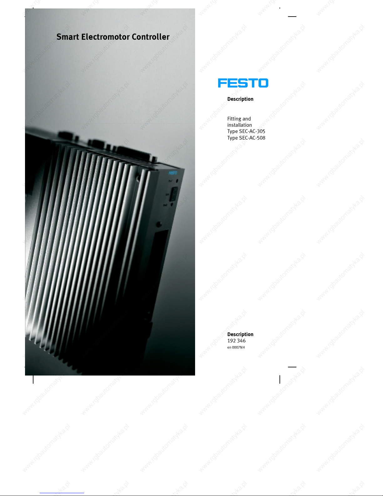
Description
Fitting and
installation
Type SEC-AC-305
Type SEC-AC-508
Description
192 346
en 0007NH
Smart Electromotor Controller
Page 2

Page 3
Contents and general instructions
I
Festo P .BE-SEC-AC-HW- EN e n 0007NH
Original de.......................................
Translation Festo AG & Co., Abtl. KI-TD.................
Layout Festo AG & Co., Ab tl. KG-GD...................
Type setting DUCOM................................
Edition en 0007NH.................................
Title MANUAL-EN.................................
Designation P.BE-SEC-AC-HW-EN......................
Order no. 192 346.................................
E (Festo AG & Co., D-73726 Esslingen, Federal Republic of
Germany
2000)
Internet: http://www.festo.com
E-Mail: service_international@festo.com
The copying, distribution and utilization of this document as
well as the communication of its contents to others without
expressed authorization is prohibited. Offenders will be held
liable for the payment of damages. All rights reserved, in
particular the right to carry out patent, utility model or
ornamental design registration.
Page 4

Contents and general instructions
II
Festo P.BE-SEC- AC-HW-EN en 0007NH
Page 5
Contents and general instructions
III
Festo P .BE-SEC-AC-HW- EN e n 0007NH
Contents
Designated use VI........................................................
Tar get group VII..........................................................
The aim of this manual VII..................................................
Trade marks VIII...........................................................
Service VIII...............................................................
Important user instructions IX..............................................
1. Summary of components 1-1........................................
1.1 Summary 1-3......................................................
1.2 Fatures 1-3.......................................................
1.3 Controller unit 1-5..................................................
1.3.1 Brief description 1-5................................................
1.3.2 Analogue-digital converter 1-5.......................................
1.3.3 Digital-analogue converter 1-5.......................................
1.3.4 Internal monitoring 1-5..............................................
1.4 Final output stage 1-6..............................................
1.4.1 Brief description 1-6................................................
1.4.2 Power supply 1-6..................................................
1.4.3 Feeding back the braking energy 1-7..................................
1.4.4 Internal monitoring 1-8..............................................
1.5 Displays 1-9......................................................
1.5.1 Brief description 1-9................................................
1.5.2 Ready-to-operate display 1-9.........................................
1.5.3 Operating mode and error display 1-9.................................
1.6 Rotary transducer evaluation 1-10.....................................
1.6.1 Serial interface 1-10.................................................
1.7 User interfaces 1-11.................................................
1.7.1 Digital inputs 1-11..................................................
1.7.2 Analogue inputs 1-11................................................
1.8 Parametrizations 1-12...............................................
1.8.1 The parameter memory 1-12..........................................
1.8.2 The parametrizing program 1-12.......................................
Page 6
Contents and general instructions
IV
Festo P.BE-SEC- AC-HW-EN en 0007NH
1.8.3 CAN module (optional) 1-12...........................................
1.9 Monitoring functions 1-13............................................
1.9.1 Brief description 1-13................................................
1.9.2 Monitoring the final output stage 1-13..................................
1.9.3 Monitoring the motor 1-14............................................
1.9.4 I2t monitoring 1-14..................................................
1.9.5 Automatic braking 1-14..............................................
2. Fitting 2-1........................................................
2.1 Dimensions 2-3....................................................
2.1.1 Dimensions of the SEC-AC 2-3........................................
2.2 Electromechanics 2-5...............................................
2.2.1 Front view 2-5.....................................................
2.2.2 Top view 2-6......................................................
2.2.3 Bottom view 2-7...................................................
3. Installation 3-1...................................................
3.1 Material 3-3.......................................................
3.1.1 Manufacturer 3-3..................................................
3.1.2 Plug for power cable X6 3-5..........................................
3.1.3 Plug for external braking resistor (only SEC-AC-508) 3-5..................
3.1.4 Plug for power supply to the SEC-AC 3-5...............................
3.1.5 PE connection of the SEC-AC 3-5......................................
3.1.6 Interface cable for serial interface (zero modem) 3-5......................
3.2 Plug c onnectors and their pin assignments 3-6..........................
3.2.1 Rotary-angle sensor cable for motors with resolver, plug X2 3-6............
3.2.2 Control signal plug with analogue monitor output X1 3-8..................
3.2.3 X10 (additional incremental sensor input) 3-10...........................
3.2.4 X11 (additional incremental sensor output) 3-11..........................
3.2.5 X5 (serial interface/serial test interface) 3-12............................
3.2.6 X6 (motor supply, power supply, parking brake and temperature sensor) 3-13.
3.2.7 Power supply cable for the SEC-AC 3-15.................................
3.3 Power supply of the SEC-AC 3-15......................................
3.3.1 X9 (power supply of the SEC-AC) 3-16...................................
Page 7
Contents and general instructions
V
Festo P .BE-SEC-AC-HW- EN e n 0007NH
3.3.2 X12 (braking resistors only SEC-AC-508) 3-16............................
3.3.3 Summary of connections 3-20.........................................
3.3.4 SEC-AC complete system 3-21.........................................
3.3.5 Connecting the PC to the SEC-AC (X5) 3-21...............................
3.3.6 Connecting the motor to the SEC-AC 3-22................................
3.3.7 Connecting the external braking resistor to the SEC-AC 3-22................
3.3.8 Connecting the SEC-AC to the power supply 3-23.........................
3.3.9 Fitting the control signal plug 3-23.....................................
3.4 Complete summary of the SEC-AC system 3-23...........................
3.4.1 Wiring the connections 3-23..........................................
3.5 PE protective conductor and screening connections 3-27...................
3.5.1 Connecting instructions 3-27..........................................
3.5.2 Electrical isolation 3-28..............................................
3.6 Measures for obser ving EMC guidelines 3-29............................
4. Diagnosis and error treatment 4-1....................................
4.1 Status display 4-3..................................................
4.2 Error messages of the SEC-AC 4-4.....................................
A. Technical Appendix A-1.............................................
A.1 Technical specifications A-3..........................................
A.1.1 SEC-AC-305 A-3....................................................
A.1.2 SEC-AC-508 A-6....................................................
A.2 Index A-9.........................................................
Page 8
Contents and general instructions
VI
Festo P.BE-SEC- AC-HW-EN en 0007NH
Designated use
The SEC-AC (Smart Electromotor Controller) has been desi-
gned for use in control cabinets for supplying AC servo mo-
tors and for controlling their torque (current), speed and posi-
tion.
TheSEC-ACmustbeoperatedinasafeworkingenvironment.
An EMERGENCY STOP circuit must be installed for the sys-
tem.
Operate the SEC-AC only under the permitted ambient condi-
tions.
The SEC-AC may only be used in stationary industrial and
commercial use. The electromagnetic interference immunity
of the power electronics is not designed for operation in mo-
bile systems, in households or firms connected directly to the
low voltage network.
Fit the SEC-AC with screening into an earthed control cabinet.
Otherwise, the electromagnetic compatibility (EMC) of the
power electronics will not be guaranteed. Use the SEC-AC
only as follows:
–asdesignated
– in a technically faultless state
– without undertaking any modifications.
If used in conjunction with additional commercially-available
components, such as sensors and actuators, the specified
maximum limits (temperatures, electrical datas, torques, etc.)
must be observed.
Please comply with national and local safety laws and regula-
tions.
Page 9
Contents and general instructions
VII
Festo P .BE-SEC-AC-HW- EN e n 0007NH
Target gro up
This manual is aimed at technicians trained in control and
automation technology, fitters etc. who
– are working for the first time with digital drive controllers
– are already familiar with digital drive controllers, but who
are installing a digital drive controller like the SEC-AC for
the first time.
The aim of this manual
This manual will help you to carry out the first commissioning
of the SEC-AC successfully.
In this manual you will find important information and acquire
the basic knowledge neceesary for operating the SEC-AC cor-
rectly.
Most work steps in this manual are divided into two parts:
– Description part: here you will learn important instruc-
tions and the aim of each individual work step.
– Instruction part: here you carry out the work step.
In the left-hand margin you will find symbols which simplify
the orientation in this manual for you during commissioning.
As this manual is intended for the first commissioning of the
complete SEC-AC product family, the regulator for which the
work step is intended is always specified for each individual
work step.
Page 10

Contents and general instructions
VIII
Festo P.BE-SEC- AC-HW-EN en 0007NH
Trade marks
All product names in this document may be registered trade
marks. All trade marks in this document are only used for
identifying the individual product.
Service
If you have any technical problems, please contact your local
Festo Service.
Page 11
Contents and general instructions
IX
Festo P .BE-SEC-AC-HW- EN e n 0007NH
Important user instructions
Danger categories
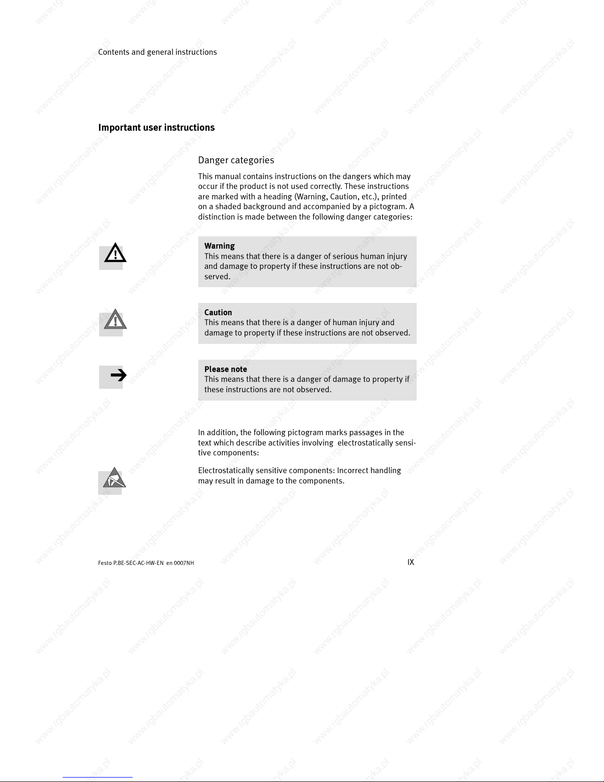
This manual contains instructions on the dangers which may
occur if the product is not used correctly. These instructions
are marked with a heading (Warning, Caution, etc.), printed
onashadedbackgroundandaccompaniedbyapictogram.A
distinction is made between the following danger categories:
Warning
This means that there is a danger of serious human injury
and damage to proper ty if these instructions are not ob-
served.
Caution
This means that there is a danger of human injury and
damage to property if these instructions are not observed.
Please note
This means that there is a danger of damage to property if
these instructions are not observed.
In addition, the following pictogram marks passages in the
text which describe activities involving electrostatically sensi-
tive components:
Electrostatically sensitive components: Incorrect handling
may result in damage to the components.
Page 12
Contents and general instructions
X
Festo P.BE-SEC- AC-HW-EN en 0007NH
Safety instructions
Warning
Inside the SEC-AC and on its connections there are high
voltages which can be extremely dangerous.
Switch off the power supply of the SEC-AC, therefore, and
wait for at least 5 minutes in order that the intermediate
circuit can discharge before you connect or disconnect any
plugs.
Warning
During installation, commissioning and maintenance you
must observe the safety and accident prevention regula-
tions valid for the specific application.
The following regulations apply but are not guaranteed to
be complete:
– VDE 0100 Regulations for setting up high-voltage sys-
tems up to 1000 V
– VDE 0113 Electrical equipment in machines
– VDE 0160 Equipment in high-voltage systems with
electronic operating methods
Page 13
Contents and general instructions
XI
Festo P .BE-SEC-AC-HW- EN e n 0007NH
Marking special information
The following pictograms mark passages in the text contain-
ing special information.
Pictograms
Information:
recommendations, tips and references to other sources of
information.
Accessories:
information on necessary or useful accessories for the Festo
product.
Environment:
information on the environmentally-friendly use of Festo
products.
Text m arkings
S The bullet denotes activities which can be carried out in
any sequence.
1. Figures denote activities which must be carried out in the
order specified.
– Hyphens denote general activities.
Page 14

Contents and general instructions
XII
Festo P.BE-SEC- AC-HW-EN en 0007NH
Page 15

Summary of components
1-1
Festo P .BE-SEC-AC-HW- EN e n 0007NH
Chapter 1
Page 16
1. Summary of components
1-2
Festo P.BE-SEC- AC-HW-EN en 0007NH
1. Summary of components 1-1........................................
1.1 Summary 1-3......................................................
1.2 Fatures 1-3.......................................................
1.3 Controller unit 1-5..................................................
1.3.1 Brief description 1-5................................................
1.3.2 Analogue-digital converter 1-5.......................................
1.3.3 Digital-analogue converter 1-5.......................................
1.3.4 Internal monitoring 1-5..............................................
1.4 Final output stage 1-6..............................................
1.4.1 Brief description 1-6................................................
1.4.2 Power supply 1-6..................................................
1.4.3 Feeding back the braking energy 1-7..................................
1.4.4 Internal monitoring 1-8..............................................
1.5 Displays 1-9......................................................
1.5.1 Brief description 1-9................................................
1.5.2 Ready-to-operate display 1-9.........................................
1.5.3 Operating mode and error display 1-9.................................
1.6 Rotary transducer evaluation 1-10.....................................
1.6.1 Serial interface 1-10.................................................
1.7 User interfaces 1-11.................................................
1.7.1 Digital inputs 1-11..................................................
1.7.2 Analogue inputs 1-11................................................
1.8 Parametrizations 1-12...............................................
1.8.1 The parameter memory 1-12..........................................
1.8.2 The parametrizing program 1-12.......................................
1.8.3 CAN module (optional) 1-12...........................................
1.9 Monitoring functions 1-13............................................
1.9.1 Brief description 1-13................................................
1.9.2 Monitoring the final output stage 1-13..................................
1.9.3 Monitoring the motor 1-14............................................
1.9.4 I2t monitoring 1-14..................................................
1.9.5 Automatic braking 1-14..............................................
Page 17
1. Summary of components
1-3
Festo P .BE-SEC-AC-HW- EN e n 0007NH
1.1 Summary
The SEC-AC servo regulators are fully digital AC servo regula-
tors which can be adapted very flexibly to a large number of
applications due to their extensive parametrizing possibi-
lities.
The SEC-AC-508 is closely related to the SEC-AC-305. Apart
from the different mains voltage and the connection for an
external braking resistor on the SEC-AC-508, the two devices
are fully compatible.
The SEC-AC Smart Electromotor Controllers must be fitted in a
control cabinet. The circuitry can be carried out in uniform
manner.
1.2 Fatures
– Full integration of all components for the controller and
power units, evaluation of the rotary transducer (motor
angle of rotation feedback) has been designed as a
plug-in module.
– Slot for technological extensions. A CANopen field bus
module as well as a Profibus module are available on re-
quest.
– Integration of all filters in the device necessary for com-
plying with the E MC regulations in operation (industrial
area), e.g. network filter, motor output filter, filter for sup-
plyaswellasfortheinputsandoutputs.
– Integrated braking module with braking chopper enables
braking energy to be dissipated via the internal braking
resistors. Only SEC-AC-508: External resistors with up to
several kW continuous output can be connected for con-
siderable braking energy.
– Only SEC-AC-305:
For increasing the braking output, an additional external
chopper with an additional braking resistor can be used.
Page 18
1. Summary of components
1-4
Festo P.BE-SEC- AC-HW-EN en 0007NH
– New mechanical concept:
The completely enclosed EMC-optimized metal housing
has been designed for direct mounting and fastening onto
the usual mounting plates in a control cabinet.
– Complete electrical isolation of the controller unit and the
final output stage, digital inputs and outputs, analogue
and control electronics in accordance with VDE 0160.
– 4-quadr ant operation with complete continuous transfer
between the quadrants.
– Droopless control in conjunction with a digital nominal
value specification.
– Sinus-shaped current injection, therefore continuous
torque compared with block-commutated controllers.
– Can be operated as a speed, torque or position regulator.
– Smooth or time-optimum positioning relatively or abso-
lutely to a reference point.
– Speed and rotary angle synchronization with electronic
gears via an incremental sensor input or CAN bus (on
request).
– Short cycle times, the control dynamics are similar to
those of an analogue regulator.
– Simple coupling to a higher-order controller, e.g. to a PLC.
– The digital controller permits error-tolerant operation, i.e.
faults are recognized in good time and regulated when
possible.
Page 19

1. Summary of components
1-5
Festo P .BE-SEC-AC-HW- EN e n 0007NH
1.3 Controller unit
1.3.1 Brief description
The central component in the controller unit is a highly inte-
grated 32-bit RISC micro controller of type HITACHI SH 7032.
Communication with higher-order controllers, PLCs or master
computers is accomplished with the optional CAN bus inter-
face, via the serial interface and via the digital inputs/out-
puts.
The ten external digital inputs and the five digital outputs are
completely electrically isolated.
1.3.2 Analogue-digital converter
The analogue-digital converter is integrated in the SEC-AC. It
digitizes analogue variables, e.g. the motor currents, ana-
logue nominal values or the temperatures of the motor and
the final output stage.
1.3.3 Digital-analogue converter
The digital-analogue conver ter serves for displaying digital
control variables on an analogue monitor. This function is of
help, e.g. with regulator optimizations. The SEC-AC has two
analogue monitor devices.
1.3.4 Internal monitoring
A watchdog timer and extensive monitoring functions ensure
very reliable operation of the controller unit.
The microcontroller and additional external hardware logic
register error signals from the motor, from the rotary-angle
evaluator and from the final output stage.
Page 20
1. Summary of components
1-6
Festo P.BE-SEC- AC-HW-EN en 0007NH
1.4 Final output stage
1.4.1 Brief description
Final output stage The final output stage is a three-phase design.
The motors should be connected star-shaped, in order to
prevent circulating currents in the motor. The intermediate
circuit voltages comply with the standard European or in-
ternational values.
Operation with lower intermediate circuit voltages is also
possible (with reduction of output). If very fast components
are used, signal distortions will be reduced to a minimum.
1.4.2 Power supply
SEC-AC-305
An external power unit is not necessary for rated outputs in
the dimensioning range. Connection is made via the single-
phase 230 V AC network.
EC-AC-508
These devices can be connected directly to the 400 V three-
phase network.
Page 21
1. Summary of components
1-7
Festo P .BE-SEC-AC-HW- EN e n 0007NH
1.4.3 Feeding back the braking energy
SEC-AC-305 and SEC -AC-508
The braking energy is fed back into the intermediate circuit
where it creates a voltage increase.
Braking chopper with
braking resistor
A braking chopper with braking resistor is integrated in the
final output stage. If a certain limit value of the intermediate
circuit voltage is exceeded during the feedback, the braking
energy will be converted to heat by the internal braking re-
sistors. Control of the braking chopper is carried out by soft-
ware in the SEC-AC. The internal braking resistors are pro-
tected against overload.
SEC-AC-508
If, in a particular application, the output of the internal resi-
stors is not sufficient, an external resistor can be connected
as described in chapter 3.3.2.
Simultaneous operation of the internal and external braking
resistors is not possible. The external resistors are not protec-
ted against overload automatically by the SEC-AC.
SEC-AC-305
If in a special, seldom used application case, the output of
the internal resistors is not sufficient, an additional external
braking chopper with additional braking resistor must be
connected to the intermediate circuit.
Further information can be obtained from Festo.
Page 22
1. Summary of components
1-8
Festo P.BE-SEC- AC-HW-EN en 0007NH
1.4.4 Internal monitoring
The final output stage will be switched off very quickly by the
controller unit if operating faults occur. A high degree of pro-
tection is ensured for the motor and the SEC-AC.
An extensive arrangement of sensors and monitoring func-
tions ensure operational safety:
– measurement of the motor temperature
– measurement of the final output stage temperature
– recognition of device-internal earth connections (protec-
tive earth)
– recognition of connections between two motor phases
only SEC-AC-508: recognition of connections at the output
for the external braking resistor
– recognition of overvoltages in the intermediate circuit
– recognition of faults in the internal voltage supply
Page 23
1. Summary of components
1-9
Festo P .BE-SEC-AC-HW- EN e n 0007NH
1.5 Displays
1.5.1 Brief description
During operation, the SEC-AC can assume various operating
states. These states are communicated to the user via visual
displays.
1.5.2 Ready-to-operate display
The green ready-to-operate LED on the front of the SEC-AC
indicates the readiness to operate.
1.5.3 Operating mode and error display
Seven segment display The seven segment display on the front of the SEC-AC indica-
tes the operating mode and shows any error messages.
Page 24
1. Summary of components
1-10
Festo P.BE-SEC- AC-HW-EN en 0007NH
1.6 Rotary transducer evaluation
The rotary transducer evaluating unit is incorporated on a
plug-in board.
Different sensor adaptions are therefore possible. As stan-
dard, the SEC-AC operates with a resolver . It also possesses
an additional incremental sensor input and an incremental
sensor output. The sensor evaluation possesses the following
features:
– a resolver resolution set at 16 bits
– an additional incremental sensor input (synchronizing
input), the resolution can be set, internal 4-fold evaluation
– an additional incremental sensor output with fixed set
resolution of 1024 inc/rev.
The incremental sensor inputs and output can be used, e.g.
for synchronizing several SEC-ACs as electronic gears.
1.6.1 Serial interface
The serial interface with RS 232 specification serves for para-
metrizing the SEC-AC. Parametrizing is carried out in conjunc-
tion with the PC parametrizing progr am for WINDOWS/NT
and a PC.
In applications in which high data transmission and the net-
working of several regulators are not required, the RS 232
can also be used for controlling the regulator.
Page 25
1. Summary of components
1-11
Festo P .BE-SEC-AC-HW- EN e n 0007NH
1.7 User interfaces
1.7.1 Digital inputs
Ten digital inputs are available for the elementary control
functions:
Positioning destination For saving positioning destinations, the SEC-AC possesses a
destination table in which the positioning destinations with
individual positioning profiles can be saved and from which
they can later be accessed. Four outputs serve for destination
selection, a fifth input is used as the starting input.
Hardware limit switches The hardware limit switches are used for setting safety limits
to the area of movement. During reference travel, one of the
two limit switches serves as the reference point for positio-
ning control.
Two inputs are used for the hardware-controlled final output
stage enable, as well as for the software-controlled regulator
enable.
A high-speed sample input can be used for synchronizing
tasks (master-slave mode).
1.7.2 Analogue inputs
The SEC-AC possesses two analogue inputs for the input le-
vel. The inputs have been designed as differential inputs, in
order to ensure a high degre of immunity to interference. The
analogue signals are digitized by the analogue-digital conver-
ter. The analogue signals serve for specifying nominal values
(speed or torque) for the regulator.
Page 26
1. Summary of components
1-12
Festo P.BE-SEC- AC-HW-EN en 0007NH
1.8 Parametrizations
1.8.1 The parameter memory
The SEC-AC possesses two memory ranges in which it stores
parameters. The FLA SH memory is used for parameters which
are loaded when the controller is switched on or after R ESET.
These parameters are retained even when the power supply
is switched off. The internal memory (RAM) is used for para-
meters which are currently used for controlling. These para-
meters can be accessed with the parametrizing program.
The FLASH technology also enables a software update (e.g.
for customer-specific software) to be loaded into the RS 232
at a later data.
1.8.2 The parametrizing program
The parametrizing program is a program for parametrizing,
controlling and monitoring the operation of the SEC-AC via
communication interfaces. It can be used with every AT-com-
patible PC as from 80486-processor with at least 16MB main
memory, providing it is running with WINDOWS 95, 98 or
WINDOWS NT. User-friendly operation under WINDOWS also
facilitates work for users with only limited EDP knowledge.
1.8.3 CA N module (optional)
The optional CAN module operates in accordance with CAN-
OPEN specifications with the CIA-DS 402 positioning profile.
Page 27
1. Summary of components
1-13
Festo P .BE-SEC-AC-HW- EN e n 0007NH
1.9 Monitoring functions
1.9.1 Brief description
The SEC-AC possesses an extensive arrangement of sensors
which monitor the faultless functioning of the controller unit,
the final output stage, the motor and the communication with
the peripherals.
Error memor Any faults which occur are saved in the internal error memory.
Most errors cause the controller unit to switch off the regula-
tor and the final output stage. The regulator cannot be swit-
ched on again until the fault has been rectified and the error
memory has been deleted by quitting (switch off the voltage
or actuate the r eset button above the figure display).
1.9.2 Monitoring the final ou tp ut stage
The final output stage is monitored by extensive protective
functions.
– Overcurrent and short-circuit monitoring:
This r eponds as s oon as the current in the intermediate
circuit exceeds twice the maximum current of the regula-
tor. Short circuits between two motor phases are recogni-
zedaswellasshortcircuitsatthemotoroutputterminals
in respect of the positive and negative reference potential
of the intermediate circuit and in respect of protective
earth. When the error monitoring recognizes an overcur-
rent, the final output stage is switched off immediately , so
that resistance to short circuits is guaranteed.
– Overvoltage monitoring for the intermediate circuit:
This responds as soon as the intermediate circuit voltage
exceeds the operating voltage range. The final output
stageisthenswitchedoff.
– Temperature monitoring for the heat sink: The heat sink
temperature of the final output stage is measured with a
linear temperature sensor. The regulator will be switched
off when a certain defined temperature is exceeded.
Page 28
1. Summary of components
1-14
Festo P.BE-SEC- AC-HW-EN en 0007NH
1.9.3 Monitoring the motor
The SEC-AC possesses the following protective functions for
monitoring the motor and the connected rotary transducer:
– Monitoring the rotary transducer:
An error of the rotary transducer causes the final output
stage to be switched off. The carrier signal and the tracer
signal are monitored.
– Measuring and monitoring the motor temperature:
The SEC-AC possesses an input for registering and moni-
toring the motor temp eratur e.
1.9.4 I2t monitoring
The SEC-AC has I2t monitoring for limiting the medium loss of
output in the final output stage and in the motor. As the loss
of output occurring in the power electronics and in the motor
increases in the most unfavourable case in squared value
with the current flowing, the digitized current value will be
accepted as a measure of the loss of output.
1.9.5 Automatic braking
The SEC-AC can directly control a parking brake with limited
current consumption of up to 0.5 A. Operation of the holding
brake can be carried out automatically with programmable
delay times.
Page 29

Fitting
2-1
Festo P .BE-SEC-AC-HW- EN e n 0007NH
Chapter 2
Page 30
2. Fitting
2-2
Festo P.BE-SEC- AC-HW-EN en 0007NH
2. Fitting 2-1........................................................
2.1 Montage der Module und Komponenten 2-3............................
2.1.1 Erdung der Endplatten 2-4...........................................
2.2 Hutschienenmontage (Typ 03) 2-6....................................
2.3 Wandmontage der Ventilinsel 2-9.....................................
Page 31
2. Fitting
2-3
Festo P .BE-SEC-AC-HW- EN e n 0007NH
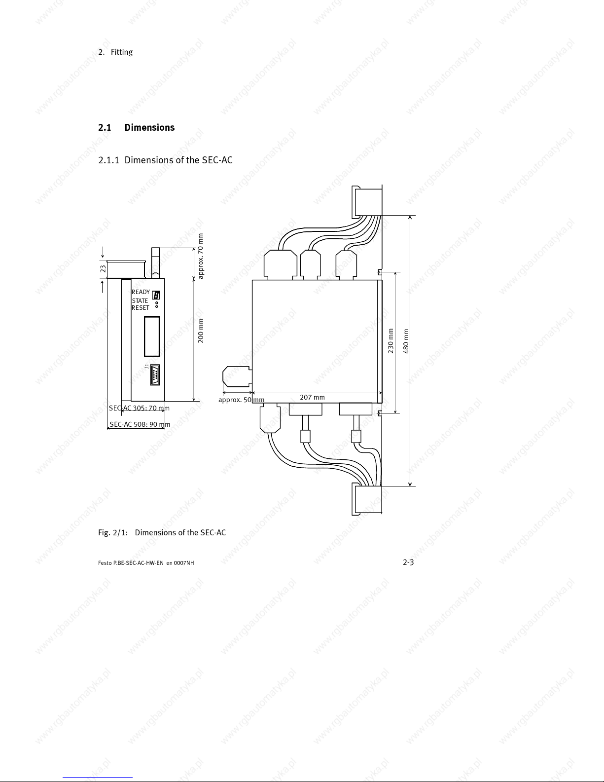
2.1 Dimensions
2.1.1 Dimensions of the SEC-AC
200 mm
207 mm
approx. 50 mm
230 mm
480 mm
SEC-AC 305: 70 mm
SEC-AC 508: 90 mm
STA TE
READY
RESET
approx. 70 mm
23
Fig. 2/1: Dimensions of the SEC-AC
Page 32
2. Fitting
2-4
Festo P.BE-SEC- AC-HW-EN en 0007NH
Please note
Connect the screening/shield with equal potential on the
mounting plate. If necessary, in the case of X10 or X11, use
an earthing screw above (e.g. with external regulators) and
always below.
Fastening screws must not be used as earthing screws.
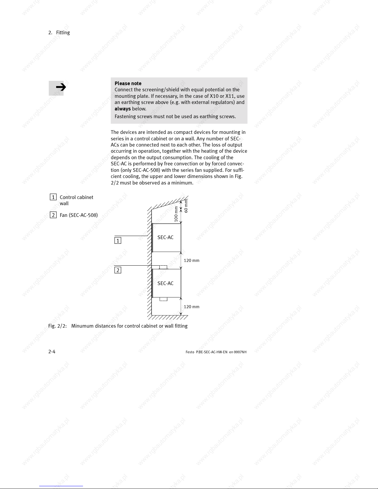
The devices are intended as compact devices for mounting in
series in a control cabinet or on a wall. Any number of SEC-
ACs can be connected next to each other. The loss of output
occurring in operation, together with the heating of the device
depends on the output consumption. The cooling of the
SEC-AC is performed by free convection or by forced convec-
tion (only SEC-AC-508) with the series fan supplied. For suffi-
cient cooling, the upper and lower dimensions shown in Fig.
2/2 must be observed as a minimum.
1 Control cabinet
wall
2 Fan (SEC-AC-508)
100 mm
120 mm
60 mm
1
2
120 mm
SEC-AC
SEC-AC
Fig. 2/2: Minumum distances for control cabinet or wall fitting
Page 33
2. Fitting
2-5
Festo P .BE-SEC-AC-HW- EN e n 0007NH
2.2 Electromechanics
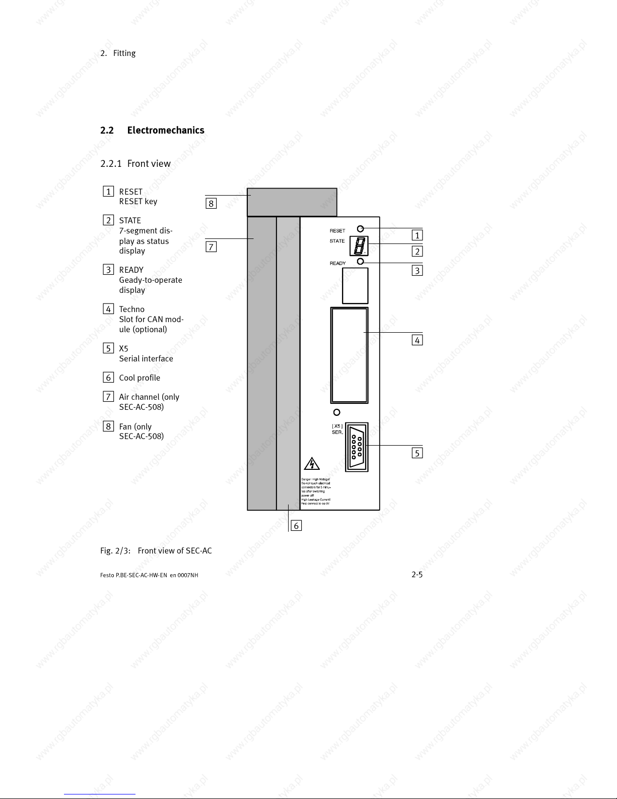
2.2.1 Front view
1
RESET
RESET key
2 STATE
7-segment dis-
play as status
display
3 READY
Geady-to-operate
display
4 Techno
Slot for CAN mod-
ule (optional)
5 X5
Serial interface
6 Cool profile
7 Air channel (only
SEC-AC-508)
8 Fan (only
SEC-AC-508)
1
2
3
4
5
6
7
8
Fig. 2/3: Front view of SEC-AC
Page 34
2. Fitting
2-6
Festo P.BE-SEC- AC-HW-EN en 0007NH
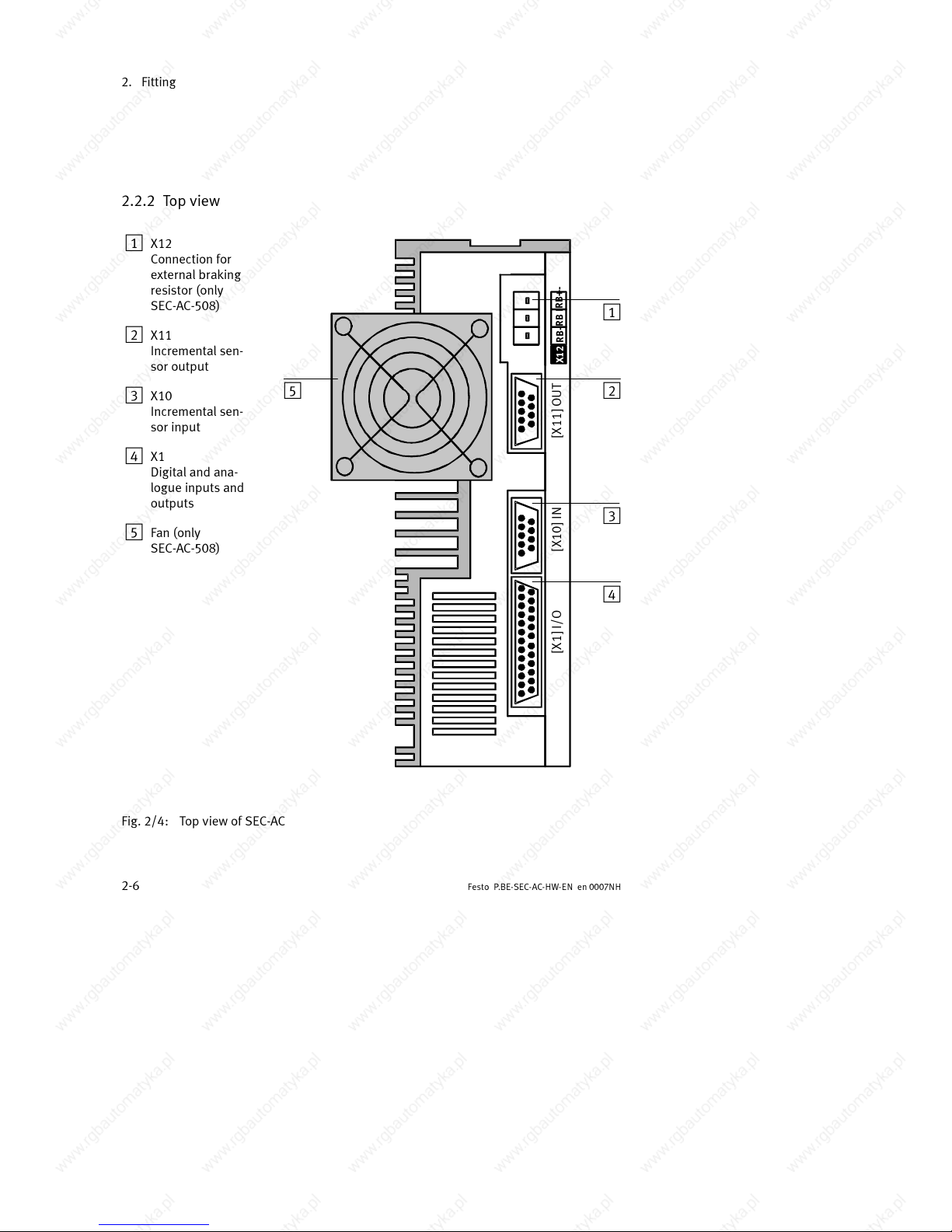
2.2.2 Top view
1
X12
Connection for
external braking
resistor (only
SEC-AC-508)
2 X11
Incremental sen-
sor output
3 X10
Incremental sen-
sor input
4 X1
Digital and ana-
logue inputs and
outputs
5 Fan (only
SEC-AC-508)
X12
[X1] I/O [X10] IN [X11] OUT
X12 RB-
RB I
RB+-
1
2
3
4
5
Fig. 2/4: Top view of SEC-AC
Page 35
2. Fitting
2-7
Festo P .BE-SEC-AC-HW- EN e n 0007NH
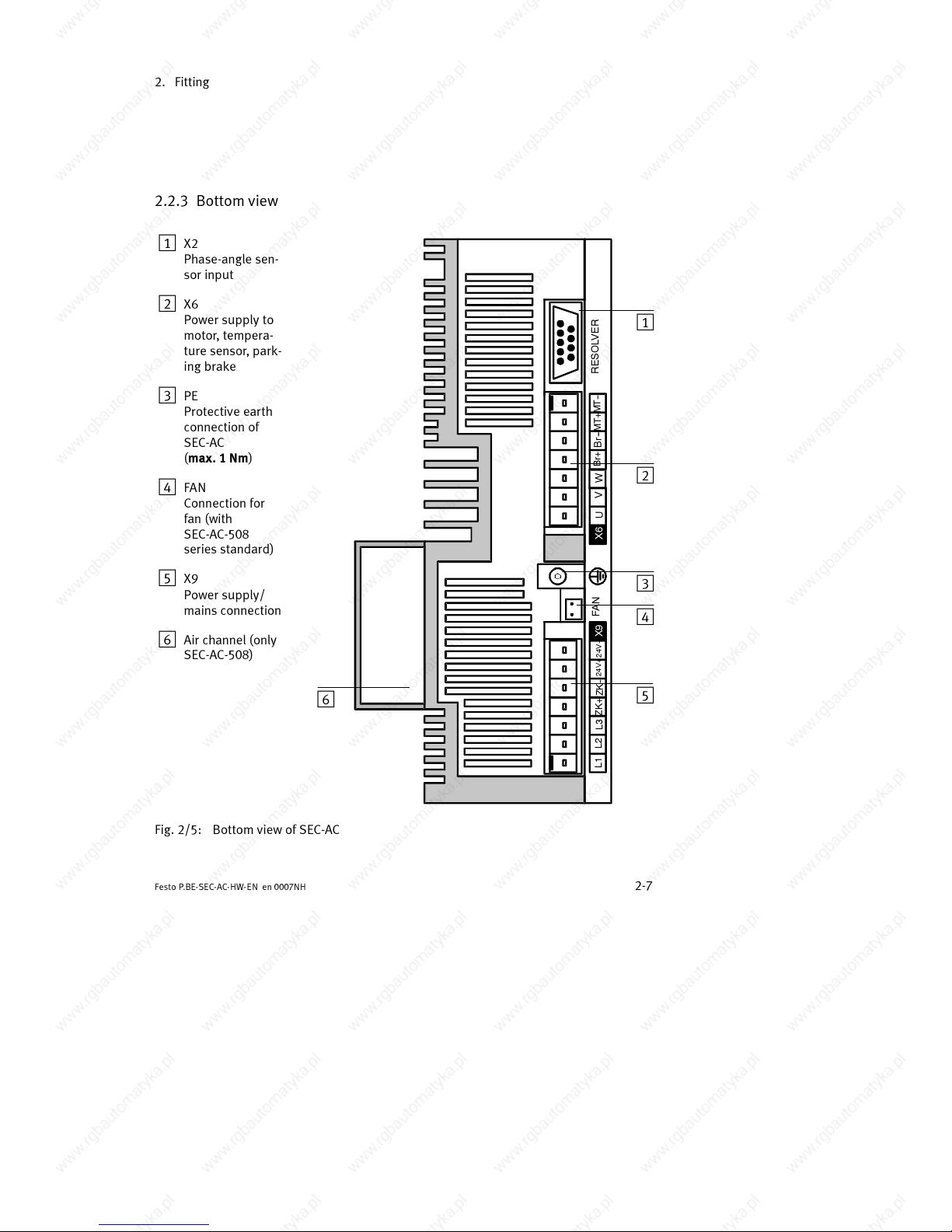
2.2.3 Bottom view
1
X2
Phase-angle sen-
sor input
2 X6
Power supply to
motor, tempera-
ture sensor, park-
ing brake
3 PE
Protective ear th
connection of
SEC-AC
(max. 1 Nm)
4 FAN
Connection for
fan (with
SEC-AC-508
series standard)
5 X9
Power supply/
mains connection
6 Air channel (only
SEC-AC-508)
U X6
L2
L3
ZK+
ZK--
24V+
24V--
RESOLVER
L1
FAN
U
V
W
Br+
MT+
Br- -
MT--
X9 X6
1
2
3
4
5
6
Fig. 2/5: Bottom view of SEC-AC
Page 36
2. Fitting
2-8
Festo P.BE-SEC- AC-HW-EN en 0007NH
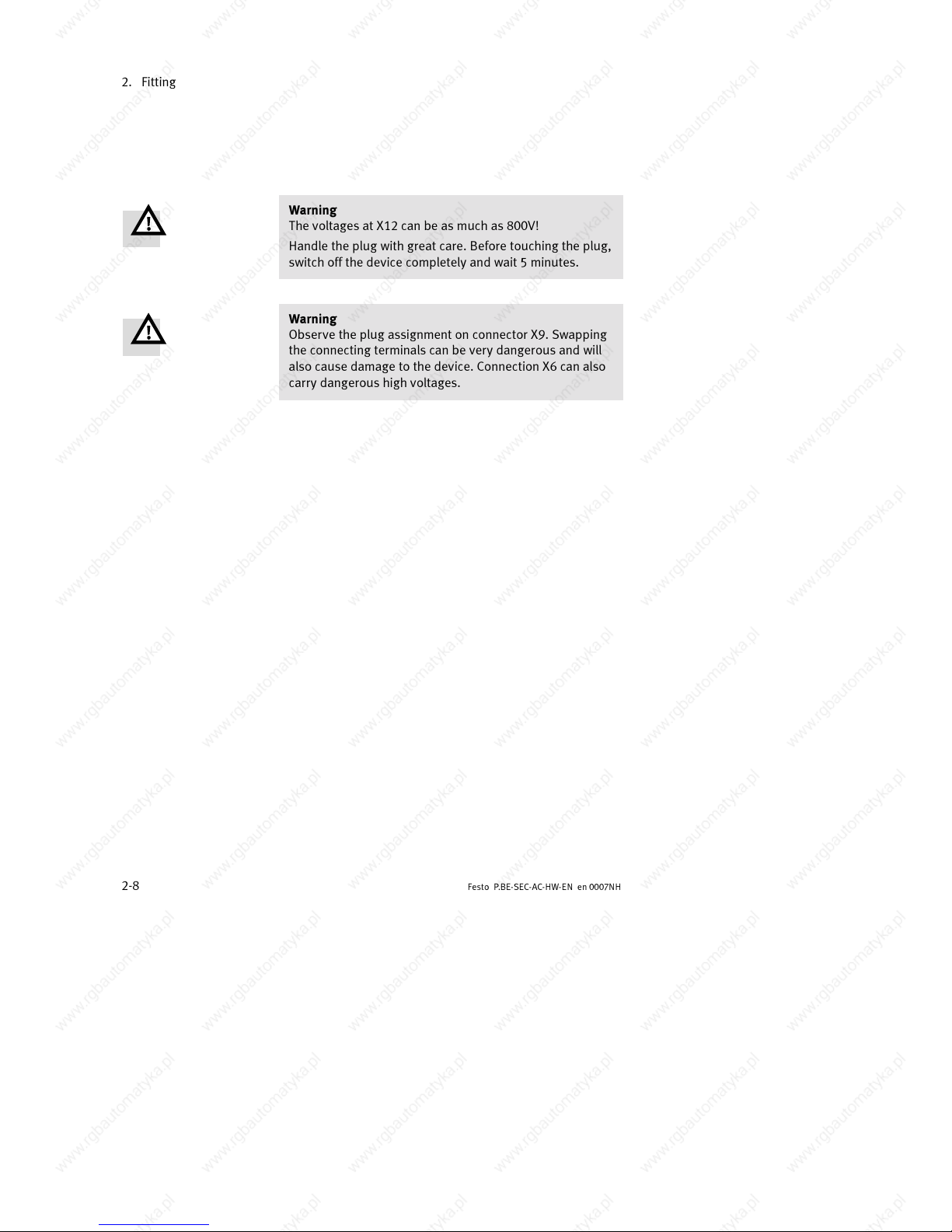
Warning
The voltages at X12 can be as much as 800V!
Handle the plug with great care. Before touching the plug,
switch off the device completely and wait 5 minutes.
Warning
Observe the plug assignment on connector X9. Swapping
the connecting terminals can be very dangerous and will
also cause damage to the device. Connection X6 can also
carry dangerous high voltages.
Page 37

Installation
3-1
Festo P .BE-SEC-AC-HW- EN e n 0007NH
Chapter 3
Page 38
3. Installation
3-2
Festo P.BE-SEC- AC-HW-EN en 0007NH
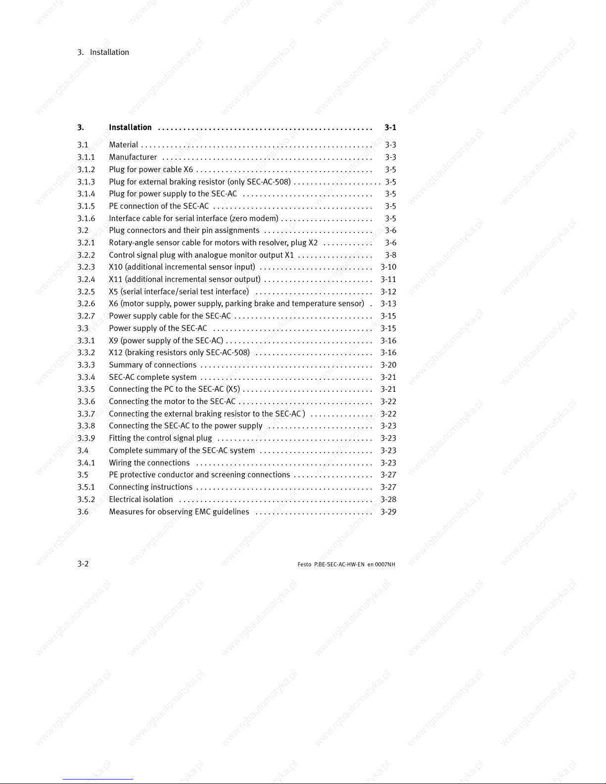
3. Installation 3-1...................................................
3.1 Material 3-3.......................................................
3.1.1 Manufacturer 3-3..................................................
3.1.2 Plug for power cable X6 3-5..........................................
3.1.3 Plug for external braking resistor (only SEC-AC-508) 3-5.....................
3.1.4 Plug for power supply to the SEC-AC 3-5...............................
3.1.5 PE connection of the SEC-AC 3-5......................................
3.1.6 Interface cable for serial interface (zero modem) 3-5......................
3.2 Plug c onnectors and their pin assignments 3-6..........................
3.2.1 Rotary-angle sensor cable for motors with resolver, plug X2 3-6............
3.2.2 Control signal plug with analogue monitor output X1 3-8..................
3.2.3 X10 (additional incremental sensor input) 3-10...........................
3.2.4 X11 (additional incremental sensor output) 3-11..........................
3.2.5 X5 (serial interface/serial test interface) 3-12............................
3.2.6 X6 (motor supply, power supply, parking brake and temperature sensor) 3-13.
3.2.7 Power supply cable for the SEC-AC 3-15.................................
3.3 Power supply of the SEC-AC 3-15......................................
3.3.1 X9 (power supply of the SEC-AC) 3-16...................................
3.3.2 X12 (braking resistors only SEC-AC-508) 3-16............................
3.3.3 Summary of connections 3-20.........................................
3.3.4 SEC-AC complete system 3-21.........................................
3.3.5 Connecting the PC to the SEC-AC (X5) 3-21...............................
3.3.6 Connecting the motor to the SEC-AC 3-22................................
3.3.7 Connecting the external braking resistor to the SEC-AC ) 3-22...............
3.3.8 Connecting the SEC-AC to the power supply 3-23.........................
3.3.9 Fitting the control signal plug 3-23.....................................
3.4 Complete summary of the SEC-AC system 3-23...........................
3.4.1 Wiring the connections 3-23..........................................
3.5 PE protective conductor and screening connections 3-27...................
3.5.1 Connecting instructions 3-27..........................................
3.5.2 Electrical isolation 3-28..............................................
3.6 Measures for obser ving EMC guidelines 3-29............................
Page 39
3. Installation
3-3
Festo P .BE-SEC-AC-HW- EN e n 0007NH
3.1 Material
3.1.1 Manufacturer
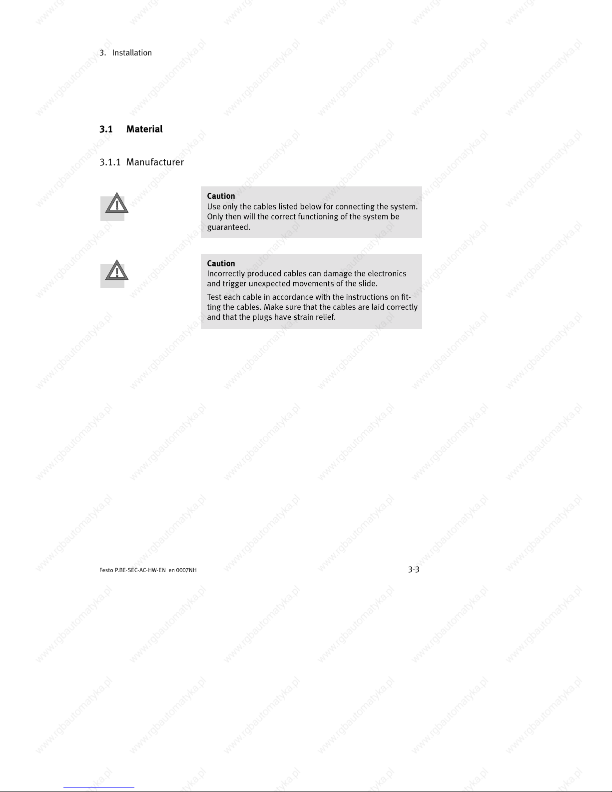
Caution
Use only the cables listed below for connecting the system.
Only then will the correct functioning of the system be
guaranteed.
Caution
Incorrectly produced cables can damage the electronics
and trigger unexpected movements of the slide.
Test each cable in accordance with the instructions on fit-
ting the cables. Make sure that the cables are laid correctly
and that the plugs have strain relief.
Page 40
3. Installation
3-4
Festo P.BE-SEC- AC-HW-EN en 0007NH
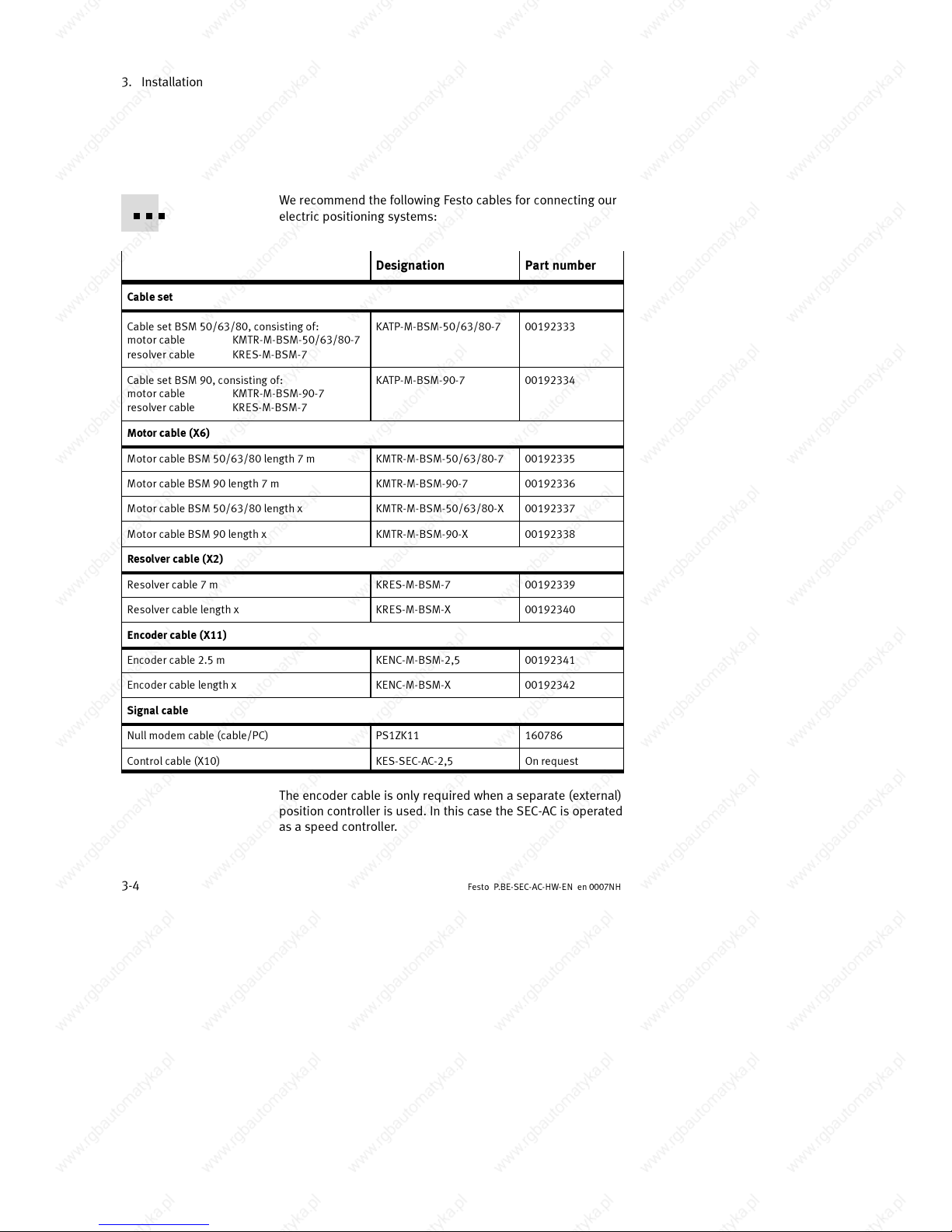
We recommend the following Festo cables for connecting our
electric positioning systems:
Designation Part number
Cable set
Cable set BSM 50/63/80, consisting of:
motor cable KMTR-M-BSM-50/63/80-7
resolver cable KRES-M-BSM-7
KATP-M-BSM-50/63/80-7 00192333
Cable set BSM 90, consisting of:
motor cable KMTR-M-BSM-90-7
resolver cable KRES-M-BSM-7
KATP-M-BSM-90-7 00192334
Motor cable (X6)
Motor cable BSM 50/63/80 length 7 m KMTR-M-BSM-50/63/80-7 00192335
Motor cable BSM 90 length 7 m KMTR-M-BSM-90-7 00192336
Motor cable BSM 50/63/80 length x KMTR-M-BSM-50/63/80-X 00192337
Motor cable BSM 90 length x KMTR-M-BSM-90-X 00192338
Resolver cable (X2)
Resolver cable 7 m KRES-M-BSM-7 00192339
Resolver cable length x KRES-M-BSM-X 00192340
Encoder cable(X11)
Encoder cable 2.5 m KENC-M-BSM-2,5 00192341
Encoder cable length x KENC-M-BSM-X 00192342
Signal cable
Null modem cable (cable/PC) PS1ZK11 160786
Control cable (X10) KES-S EC-AC-2,5 On request
The encoder cable is only required when a separate (external)
position controller is used. In this case the SEC-AC is operated
as a speed controller.
Page 41
3. Installation
3-5
Festo P .BE-SEC-AC-HW- EN e n 0007NH
3.1.2 Plug for power cable X6
1 PHOENIX POWER-COMBICON plug, 7-pole without pins grid
7.62mm, PC 4/7-ST-7.62, included in delivery. Coding profile
to avoid swapping the connections CP-HCC 4.
3.1.3 Plug for external braking resistor (only SEC -AC-508)
(recommended for high braking power)
1 PHOENIX POWER-COMBICON plug, 3-pole without pins grid
7.62mm, PC 4/3-ST-7.62.
Included in delivery (inserted in X12). Remo ve the wire
bridges on the plug if using an external braking resistor.
3.1.4 Plug for power supply to the SEC-AC
1 PHOENIX POWER-COMBICON plug, 7-pole without pins grid
7.62mm, PC 4/7-ST-7.62, included in delivery. Coding profile
to avoid swapping the connections CP-HCC 4.
3.1.5 PE connection of the SEC-AC
Please use Festo cables.
The PE connection of the SEC-AC (network and motor) is
made with an M5 threaded pin.
3.1.6 Interface cable for serial interface (zero modem)
2 D-SUB plug, 9-pin socket 2 housing for 9-pin D-SUB plug
with locking screws 4/40 UNC screened cable, 3-core
Page 42

3. Installation
3-6
Festo P.BE-SEC- AC-HW-EN en 0007NH
3.2 Plug connectors and their pin assignments
3.2.1 Rotary-angle sensor cable for motors with resolver, plug X2
(rotary-angle sensor evaluation)
– plug connector: D-Sub socket 9-pin
– mating connector: D-Sub plug 9-pin
The outer screening is always connected to protective earth
(PE) (plug housing).
Page 43
3. Installation
3-7
Festo P .BE-SEC-AC-HW- EN e n 0007NH
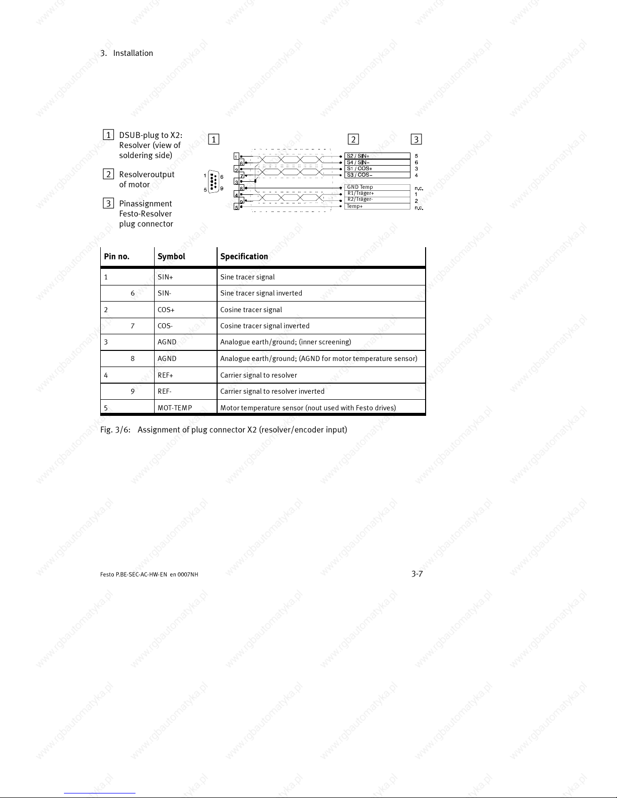
1 DSUB-plug to X2:
Resolver (view of
soldering side)
2 Resolveroutput
of motor
3 Pinassignment
Festo-Resolver
plug connector
123
GND Temp
R1/Träger+
R2/Träger-
Temp+
Pin no. Symbol Specification
1 SIN+ Sine tracer signal
6 SIN- Sine tracer signal inverted
2 COS+ Cosine tracer signal
7 COS- Cosine tracer signal inverted
3 AGND Analogue ear th/ground; (inner screening)
8 AGND Analogue ear th/ground; (AGND for motor temperature sensor)
4 REF+ Carrier signal to resolver
9 REF- Carrier signal to resolver inverted
5 MOT-TEMP Motor tempe rature sensor (nout used with Festo drives)
Fig. 3/6: Assignment of plug connector X2 (resolver/encoder input)
Page 44
3. Installation
3-8
Festo P.BE-SEC- AC-HW-EN en 0007NH
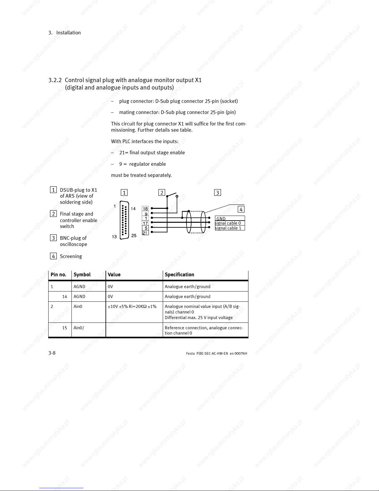
3.2.2 Control signal plug with analogue monitor output X1
(digital and analogue inputs and outputs)
– plug connector: D-Sub plug connector 25-pin (socket)
– mating connector: D-Sub plug connector 25-pin (pin)
This circuit for plug connector X1 will suffice for the first com-
missioning. Further details see table.
With PLC interfaces the inputs:
– 21= final output stage enable
– 9= regulatorenable
must be treated separately.
1 DSUB-plug to X1
of ARS (view of
soldering side)
2 Final stage and
controller enable
switch
3 BNC-plug of
oscilloscope
4 Screening
12 3
4
GND
signal cable 0
signal cable 1
Pin no. Symbol Value Specification
1 AGND 0V Analogue earth/ground
14 AGND 0V Analogue earth/ground
2 Ain0 ±10V ±5% Ri=20KW±1% Analogue nominal value input (A/B sig-
nals) channel 0
Differential max. 25 V input voltage
15 Ain0/ Reference connection, analogue connec-
tion channel 0
Page 45
3. Installation
3-9
Festo P .BE-SEC-AC-HW- EN e n 0007NH
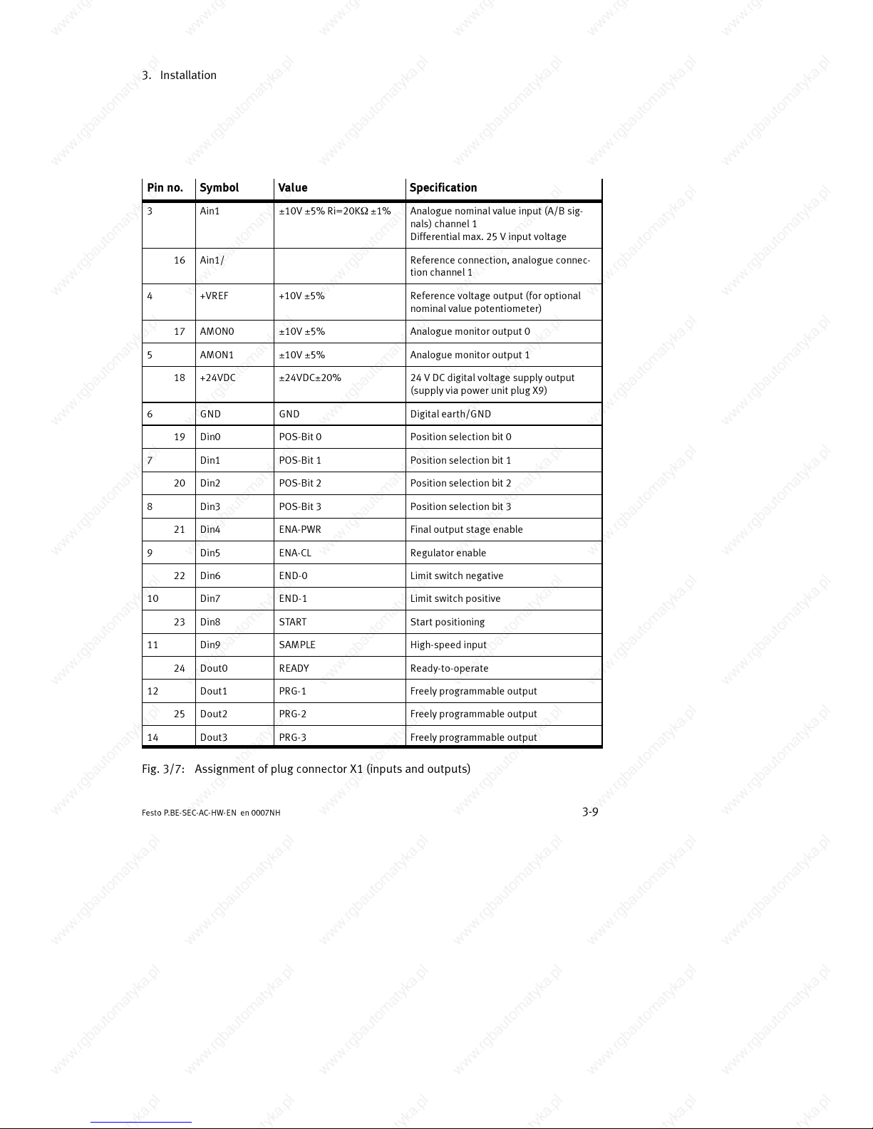
Pin no. SpecificationValueSymbol
3 Ain1 ±10V ±5% Ri=20KW±1% Analogue nominal value input (A/B sig-
nals) channel 1
Differential max. 25 V input voltage
16 Ain1/ Reference connection, analogue connec-
tion channel 1
4 +VREF +10V ±5% Reference voltage output (for optional
nominal value potentiometer)
17 AMON0 ±10V ±5% Analogue monitor output 0
5 AMON1 ±10V ±5% Analogue monitor output 1
18 +24VDC ±24VDC±20% 24 V DC digital voltage supply output
(supply via power unit plug X9)
6 GND GND Digital earth/GND
19 Din0 POS-Bit 0 Position selectionbit 0
7 Din1 POS-Bit 1 Position selection bit 1
20 Din2 POS-Bit 2 Position selectionbit 2
8 Din3 POS-Bit 3 Position selection bit 3
21 Din4 ENA-PWR Final output stage enable
9 Din5 ENA-CL Regulator enable
22 Din6 END-0 Limit switch negative
10 Din7 END-1 Limit switch positive
23 Din8 START Start positioning
11 Din9 SAMPLE High-speed input
24 Dout0 READY Ready-to-operate
12 Dout1 PRG-1 Freely programmable output
25 Dout2 PRG-2 Freely programmable output
14 Dout3 PRG-3 Freely programmable output
Fig. 3/7: Assignment of plug connector X1 (inputs and outputs)
Page 46
3. Installation
3-10
Festo P.BE-SEC- AC-HW-EN en 0007NH
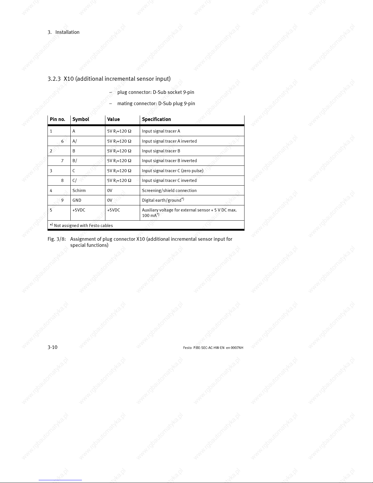
3.2.3 X10 (additional incremental sensor input)
– plug connector: D-Sub socket 9-pin
– mating connector: D-Sub plug 9-pin
Pin no.
Symbol Va lue Specification
1 A 5V R
i
»120 W Input signal tracer A
6 A/ 5V R
i
»120 W Input signal tracer A inverted
2 B 5V R
i
»120 W Input signal tracer B
7 B/ 5V R
i
»120 W Input signal tracer B inverted
3 C 5V R
i
»120 W Input signal tracer C (zero pulse)
8 C/ 5V R
i
»120 W Input signal tracer C inverted
4 Schirm 0V Screening/shield connection
9 GND 0V Digital earth/ground
*)
5 +5VDC +5VDC Auxiliary voltage for external sensor + 5 V DC max.
100 mA
*)
*)Not assigned with Festo cables
Fig. 3/8: Assignment of plug connector X10 (additional incremental sensor input for
special functions)
Page 47
3. Installation
3-11
Festo P .BE-SEC-AC-HW- EN e n 0007NH
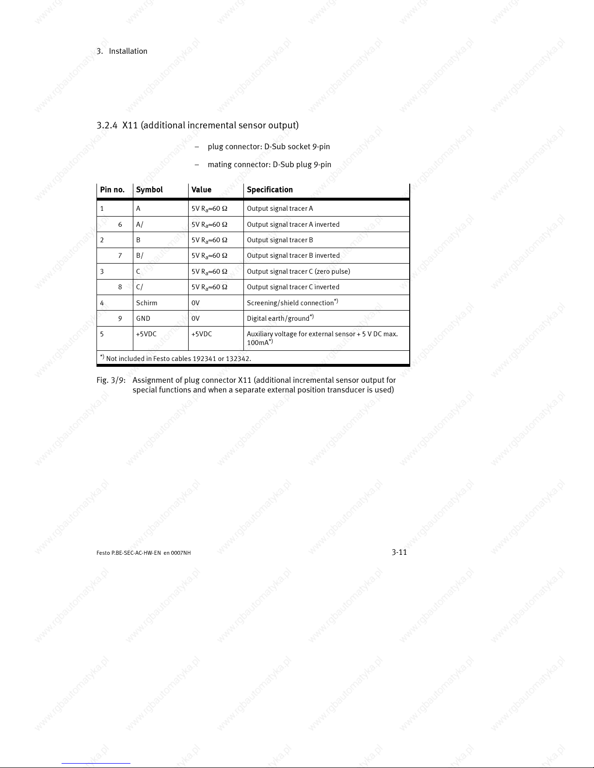
3.2.4 X11 (additional incremental sensor output)
– plug connector: D-Sub socket 9-pin
– mating connector: D-Sub plug 9-pin
Pin no.
Symbol Va lue Specification
1 A 5V R
a
»60 W Output signal tracer A
6 A/ 5V R
a
»60 W Output signal tracer A inverted
2 B 5V R
a
»60 W Output signal tracer B
7 B/ 5V R
a
»60 W Output signal tracer B inverted
3 C 5V R
a
»60 W Output signal tracer C (zero pulse)
8 C/ 5V R
a
»60 W Output signal tracer C inverted
4 Schirm 0V Screening/shield connection
*)
9 GND 0V Digital earth/ground
*)
5 +5VDC +5VDC Auxiliary voltage for external sensor + 5 V DC max.
100mA
*)
*)
Not includedinFestocables192341 or 132342.
Fig. 3/9: Assignment of plug connector X11 (additional incremental sensor output for
special functions and when a separate external position transducer is used)
Page 48
3. Installation
3-12
Festo P.BE-SEC- AC-HW-EN en 0007NH
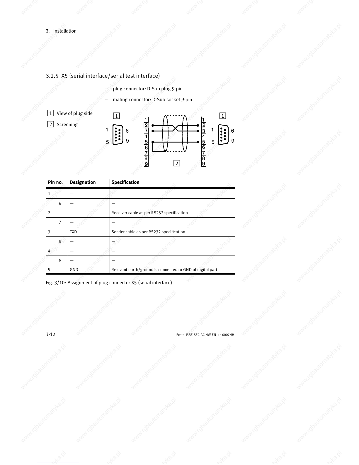
3.2.5 X5 (serial interface/serial test interface)
– plug connector: D-Sub plug 9-pin
– mating connector: D-Sub socket 9-pin
1 View of plug side
2 Screening
11
2
Pin no. Designation Specification
1 — —
6 — —
2 Receiver cable as per RS232 specification
7 — —
3 TXD Sender cable as per RS232 specification
8 — —
4 — —
9 — —
5 GND Relevant earth/ground is connected to GND of digital part
Fig. 3/10: Assignment of plug connector X5 (serial interface)
Page 49
3. Installation
3-13
Festo P .BE-SEC-AC-HW- EN e n 0007NH
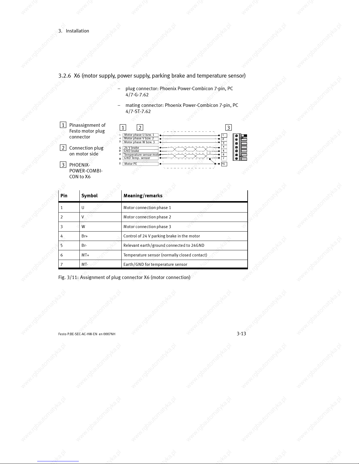
3.2.6 X6 (motor supply, power supply, parking brake and temperat ur e sensor)
– plug connector: Phoenix Power-Combicon 7-pin, PC
4/7-G-7.62
– mating connector: Phoenix Power-Combicon 7-pin, PC
4/7-ST-7.62
1 Pinassignment of
Festo motor plug
connector
2 Connection plug
on motor side
3 PHOENIX-
POWER-COMBI-
CON to X6
12 3
Motor phase U bzw. 1
Motor phase V bzw. 2
Motor phase W bzw. 3
24 V b rake
GN D brake
Temperature sensor motor
GND Temp. sensor
Motor PE
Pin Symbol Meaning/remarks
1 U Motor connection phase 1
2 V Motor connection phase 2
3 W Motor connection phase 3
4 Br+ Control of 24 V parking brake in the motor
5 Br- Relevant earth/ground connected to 24GND
6 MT+ Temperature sensor (normally closed contact)
7 MT- Earth/GND for temperature sensor
Fig. 3/11: Assignment of plug connector X6 (motor connection)
Page 50
3. Installation
3-14
Festo P.BE-SEC- AC-HW-EN en 0007NH
Please note
The temperature sensor in the motor (normally-closed con-
tact) can be wired either via the the sensor cable or the
power cable (depending on the motor). The unused con-
nection remains in each case unwired.
In Festo drive packages the temperature sensor is wired
via the motor cable.
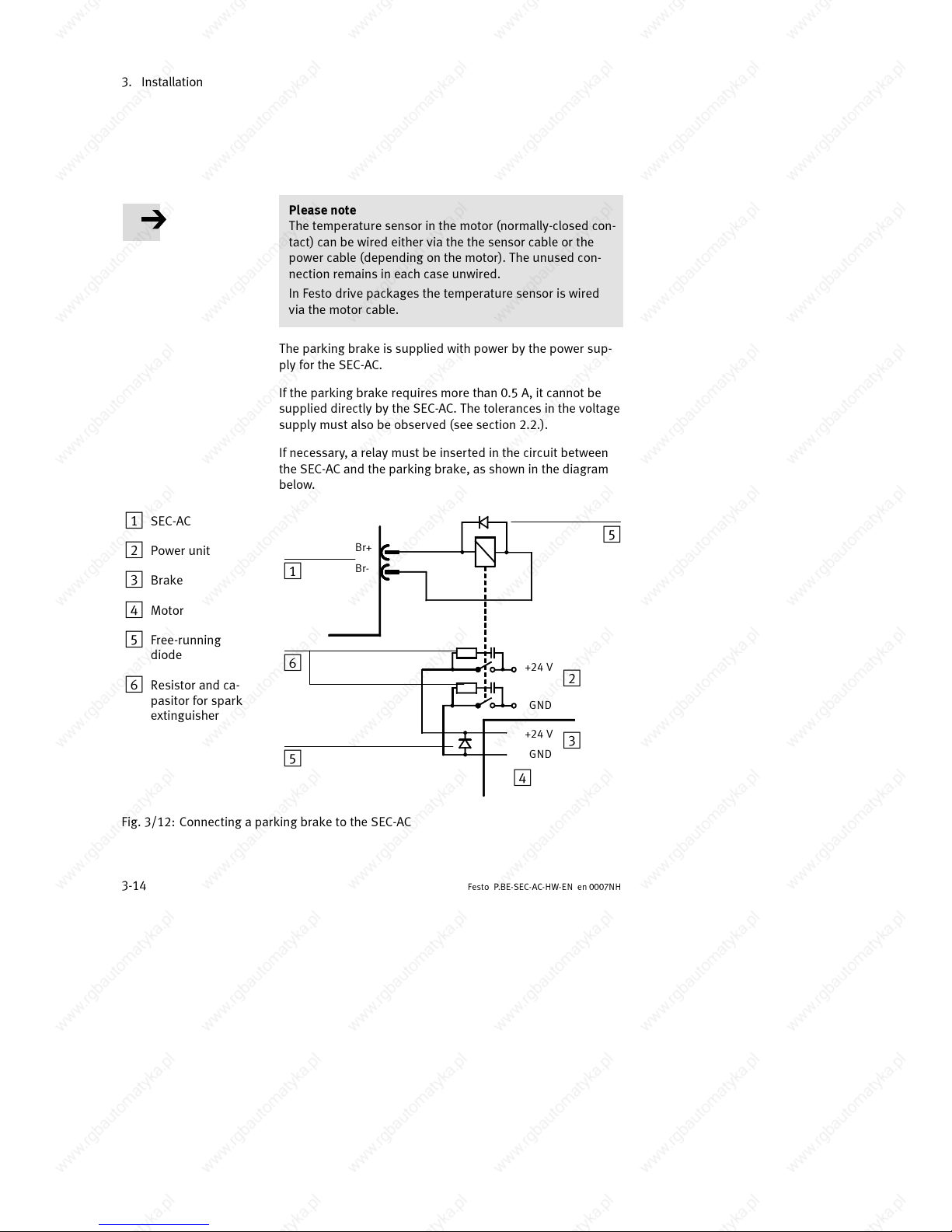
The parking brake is supplied with power by the power sup-
ply for the SEC-AC.
If the parking brake requires more than 0.5 A, it cannot be
supplied directly by the SEC-AC. The tolerances in the voltage
supply must also be observed (see section 2.2.).
If necessary, a relay must be inserted in the circuit between
the SEC-AC and the parking brake, as shown in the diagram
below.
1 SEC-AC
2 Power unit
3 Brake
4 Motor
5 Free-running
diode
6 Resistor and ca-
pasitor for spark
extinguisher
Br+
Br-
+24 V
GND
GND
+24 V
1
2
3
4
5
6
5
Fig. 3/12: Connecting a parking brake to the SEC-AC
Page 51
3. Installation
3-15
Festo P .BE-SEC-AC-HW- EN e n 0007NH
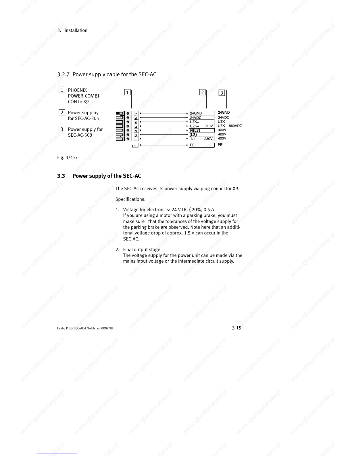
3.2.7 Power supply cable for the SEC-AC
1
PHOENIX
POWER-COMBI-
CON to X9
2 Power suppluy
for SEC-AC-305
3 Power supply for
SEC-AC-508
12
3
N(L3)
(L2)
Fig. 3/13:
3.3 Power supply of the SEC-AC
The SEC-AC receives its power supply via plug connector X9.
Specifications:
1. Voltage for electronics: 24 V DC ( 20%, 0.5 A
If you are using a motor with a parking brake, you must
make sure that the tolerances of the voltage supply for
the parking brake are observed. Note here that an additi-
tonal voltage drop of approx. 1.5 V can occur in the
SEC-AC.
2. Final output stage
Thevoltagesupplyforthepowerunitcanbemadeviathe
mains input voltage or the intermediate circuit supply.
Page 52
3. Installation
3-16
Festo P.BE-SEC- AC-HW-EN en 0007NH
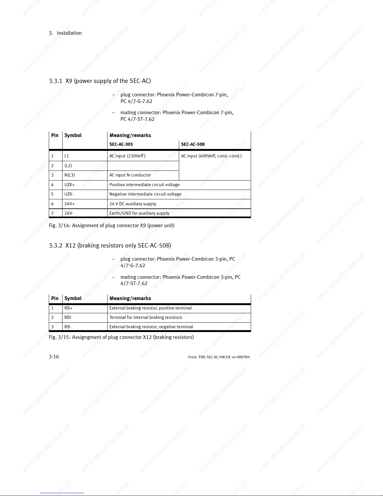
3.3.1 X9 (power supply of the SEC-AC)
– plug connector: Phoenix Power-Combicon 7-pin,
PC 4/7-G-7.62
– mating connector: Phoenix Power-Combicon 7-pin,
PC 4/7-ST-7.62
Pin
Symbol Meaning/remarks
SEC-AC-305 SEC-AC-508
1 L1 AC input (230Veff) AC input (400Veff, cond.-cond.)
2 (L2)
3 N(L3) AC input N-conductor
4 UZK+ Positive intermediate circuit voltage
5 UZK- Negative intermediate circuit voltage
6 24V+ 2 4 V DC auxiliary supply
7 24V- Earth/GND for auxiliary supply
Fig. 3/14: Assignment of plug connector X9 (power unit)
3.3.2 X12 (braking resistors only SEC-AC-508)
– plug connector: Phoenix Power-Combicon 3-pin, PC
4/7-G-7.62
– mating connector: Phoenix Power-Combicon 3-pin, PC
4/7-ST-7.62
Pin
Symbol Meaning/remarks
1 RB+ Ext ernal braking resistor, positive terminal
2 RBI Terminal for internal braking resistors
3 RB- External braking resistor, negative terminal
Fig. 3/15: Assigngment of plug connector X12 (braking resistors)
Page 53
3. Installation
3-17
Festo P .BE-SEC-AC-HW- EN e n 0007NH
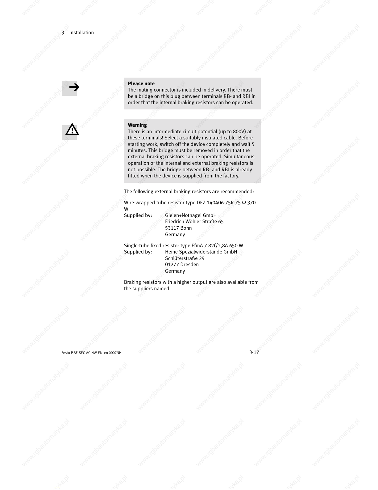
Please note
The mating connector is included in delivery. There must
be a bridge on this plug between terminals RB- and RBI in
order that the internal braking resistors can be operated.
Warning
There is an intermediate circuit potential (up to 800V) at
these terminals! Select a suitably insulated cable. Before
starting work, switch off the device completely and wait 5
minutes. This br idge must be removed in order that the
external braking resistors can be operated. Simultaneous
operation of the internal and external braking resistors is
not possible. The bridge between RB- and RBI is already
fitted when the device is supplied from the factory.
The following external braking resistors are recommended:
Wire-wrapped tube resistor type DEZ 140406-75R 75
9 370
W
Supplied by: Gielen+Notnagel GmbH
Friedrich Wöhler Straße65
53117 Bonn
Germany
Single-tube fixed resistor type EfmA 7 82(/2,8A 650 W
Supplied by: Heine Spezialwiderstände GmbH
Schlüterstraße29
01277 Dresden
Germany
Braking resistors with a higher output are also available from
the suppliers named.
Page 54
3. Installation
3-18
Festo P.BE-SEC- AC-HW-EN en 0007NH
Fitting the connecting cable
Please note
Connection to the mains power supply and the fitting of
mains switches, transformers, safety devices and network
filters may only be carried out by qualified personnel.
Caution
S Do not connect any cable to the electronics and do not
disconnect any cable while the system is still connected
to the power supply. Otherwise the device will be dam-
aged.
S Before installation, check all the cables once again, as
incorrect connection assignments may lead to serious
malfunctioning.
S Disconnect the SEC-AC and the motor from the mains
power supply and wait 5 minutes (for intermediate cir-
cuit discharge) before you connect or disconnect any
plugs.
S Always connect the SEC-AC to the protective earth (PE)
of the power supply network.
S Always connect the screening cables of the motor to the
earth connection of the SEC-AC before you commission
the motor.
Caution
Avoid the parallel routing of motor cables and signal
cables over long distances. Use only screened cables for
connecting the motor and paired twisted cables for the
signal cables.
Page 55
3. Installation
3-19
Festo P .BE-SEC-AC-HW- EN e n 0007NH
In this way you will avoid electromagnetic interference which
can impair reliable operation of the system.
Caution
Make sure that the cables are fitted with strain relief. With
beam and multi-axis operation, mechanically stressed
cables must be laid in a drag chain.
Page 56
3. Installation
3-20
Festo P.BE-SEC- AC-HW-EN en 0007NH
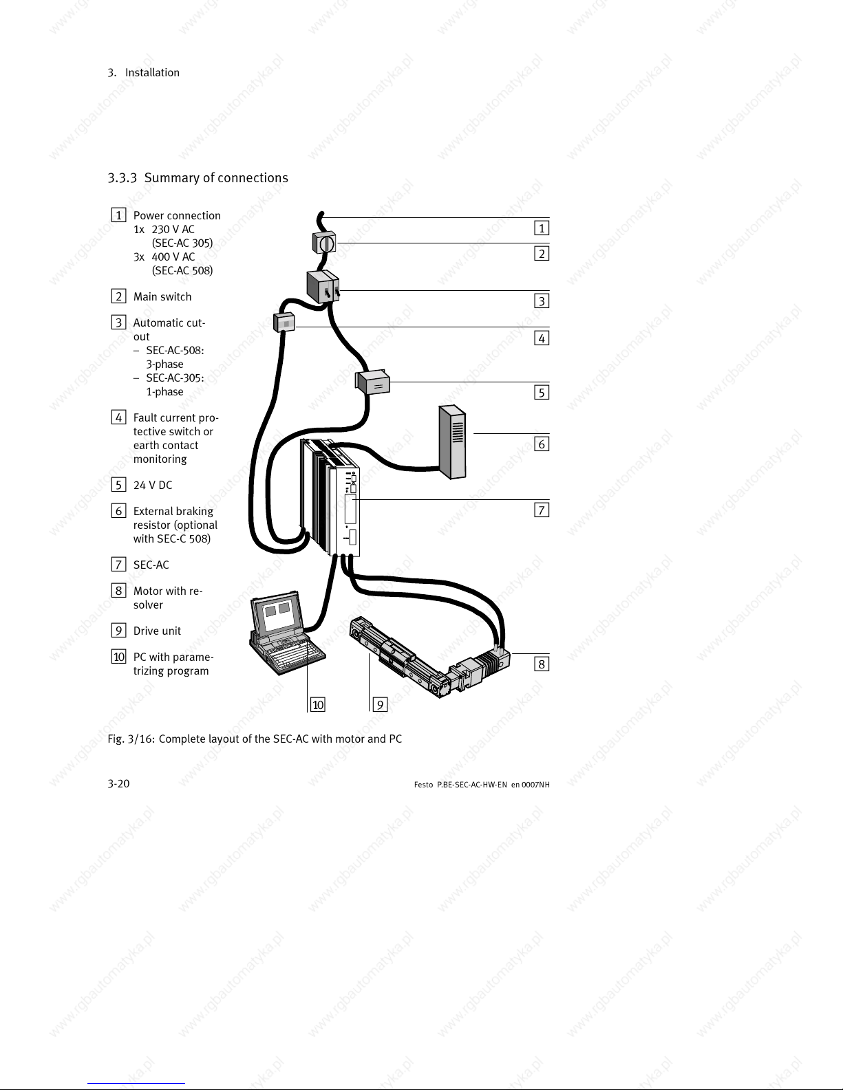
3.3.3 Summary of connections
1
Power connection
1x 230 V AC
(SEC-AC 305)
3x 400 V AC
(SEC-AC 508)
2 Main switch
3 Automatic cut-
out
– SEC-AC-508:
3-phase
– SEC-AC-305:
1-phase
4 Fault current pro-
tective switch or
earth contact
monitoring
5 24 V DC
6 External braking
resistor (optional
with SEC-C 508)
7 SEC-AC
8 Motor with re-
solver
9 Drive unit
aJ PC with parame-
trizing program
1
2
3
4
5
6
7
8
9aJ
Fig. 3/16: Complete layout of the SEC-AC with motor and PC
Page 57
3. Installation
3-21
Festo P .BE-SEC-AC-HW- EN e n 0007NH
3.3.4 SEC-AC complete system
The diagram in Fig. 3/16 on the previous page represents the
complete SEC-AC system. The following components are re-
quired for operating the SEC-AC:
SEC-AC
– Mains power switch
– Automatic circuit breaker
– FI protective switch (depending on design guideline alter-
native Ground current registering)
– SEC-AC
– Motor with motor cable
– Network cable
– A PC with serial connecting cable will be required for
parametrizing.
3.3.5 Connecting the PC to the SEC-AC (X5)
1. InserttheD-Subplugoftheserialinterfacecableintothe
socket for the serial interface of the PC. Tighten the lock-
ing screws.
2. InserttheD-Subplugoftheserialinterfacecableinto
socket X5:SER of the SEC-AC. stecken. Tighten the lock-
ing screws.
3. Check all plug connectors again.
Page 58
3. Installation
3-22
Festo P.BE-SEC- AC-HW-EN en 0007NH
3.3.6 Connecting the motor to the SEC-AC
1. Insert the plug for the power cable into the appropriate
socket on the motor and tighten it.
2. Insert the PHOENIX plug into socket X6 on the SEC-AC.
3. Connect the PE cable of the motor and the screening
cable to the PE earth terminal of the SEC-AC.
4. Insert the resolver plug into the resolver output socket on
the motor and tighten it.
5. Insert the 9-pin D-Sub resolver plug into socket X2 on the
SEC-AC and tighten the locking screws.
6. Connect the screening connection of the resolver cable to
the P E earth terminal of the SEC-AC.
7. Check all plug and screening connectors again.
3.3.7 Connecting the external braking resistor to the SEC-AC (if required,
only with SEC-AC-508)
1. Make sure that the power supply is switched off (wait at
least 5 minutes).
2. Connect the housing of the braking resistor to the PE (e.g.
on the SEC-AC).
3. Remo ve the bridge betwen RB- and RBI on connector
X12.
4. Connect the braking resistor to terminals RB+ and RB- of
connector X12.
Page 59
3. Installation
3-23
Festo P .BE-SEC-AC-HW- EN e n 0007NH
3.3.8 Connecting the SEC- AC to the p ower supply
1. Make sure that the power supply is switched off.
2. Insert the PHOENIX plug into socket X9 on the SEC-AC.
3. Connect the PE-cable of the network to the PE earth ter-
minal.
3.3.9 Fitting the control signal plug
1. Insert the control signal plug into socket X1 on the
SEC-AC. Tighten the locking screws.
Warning
When connecting the motor phases, note that different
manufacturers of servo motors specify different phase
sequences. If necessary, phases U and W must be
swapped.
3.4 Complete summary of the SEC-AC system
3.4.1 Wiring the connections
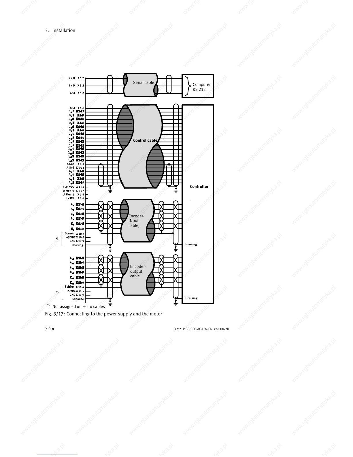
The SEC-AC should be connected to the power supply and to
the motor as shown in Fig. 3/17.
Page 60
3. Installation
3-24
Festo P.BE-SEC- AC-HW-EN en 0007NH
Computer
RS 232
Controller
Serial cable
Control cable
Encoder-
INput
cable
Encoder-
output
cable
*)
Not assigned on Fest o cable s
Housing
Screen.
Gehäuse
Schirm
*)
Housing
HOusing
*)
Fig. 3/17: Connecting to the power supply and the motor
Page 61
3. Installation
3-25
Festo P .BE-SEC-AC-HW- EN e n 0007NH
Power unit 24 V
Logic supply
cable
Power cable
Chopper cable
Motor cable
Resolver
cable
Motor
Breaking resistor
Housing
PE-earth terminal
Housing
Phase 1 U
Phase 2 V
Phase 3 W
1)
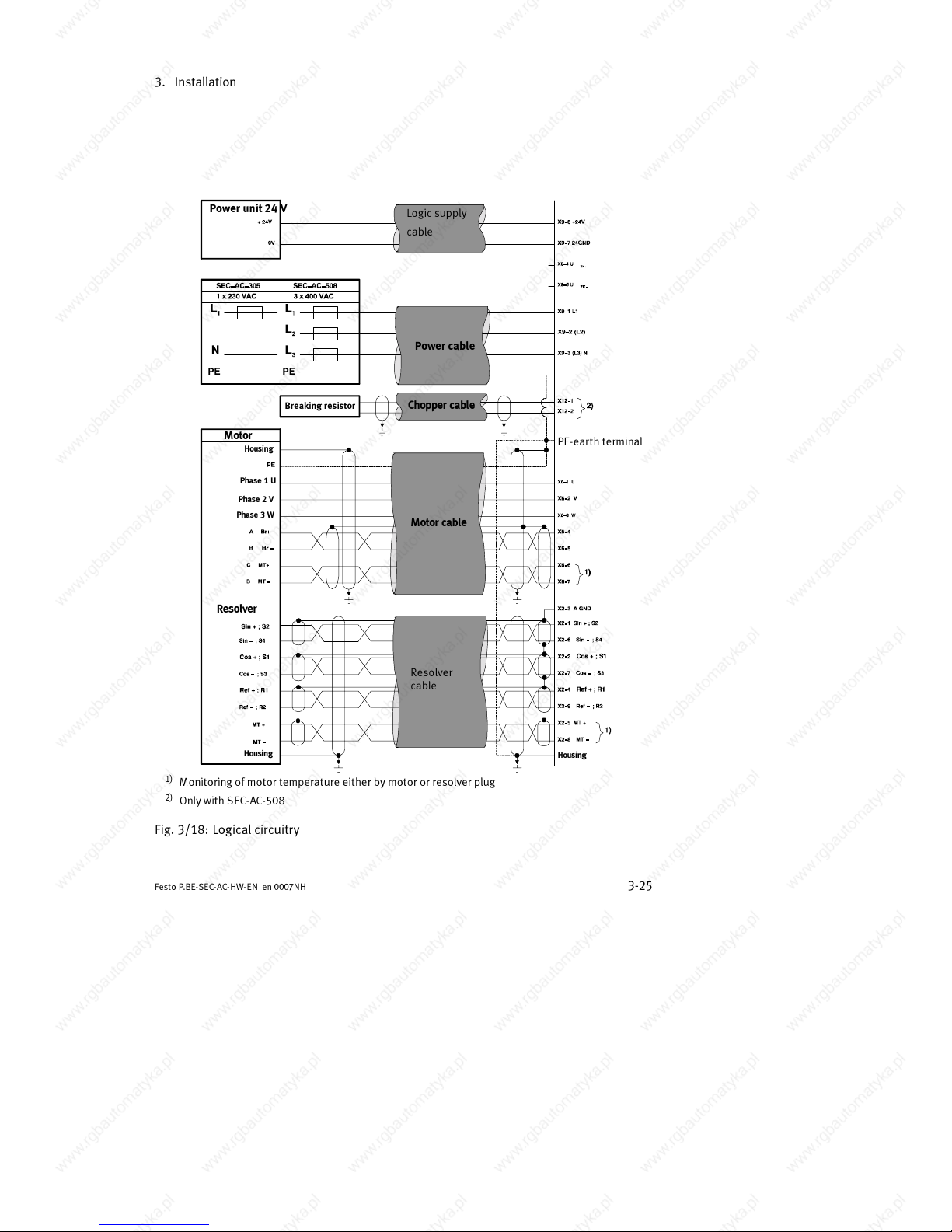
Monitoring of motor temperature either by motor or resolver plug
2)
OnlywithSEC-AC-508
Housing
Resolver
Fig. 3/18: Logical circuitry
Page 62
3. Installation
3-26
Festo P.BE-SEC- AC-HW-EN en 0007NH
Caution
The SEC-AC-508 does not have internal fuses for the
400V
AC
- or 560VDC-inputs. An automatic circuit breaker is
therefore provided. If the SEC-AC-508 is operated with only
one or two current phases, high PE-leakage currents may
occur. Only one automatic circuit breaker, in which all three
phases are switched off together, may therefore be used.
Caution
The SEC-AC must first be connected to X1, X10...X12. The
operating voltages for the intermediate circuit and the
electronic DC voltage supply must not be switched on until
commissioning is started. If the operating voltage connec-
tions are connected with incorret polarity, or if there is ex-
cessive operating voltage, or if the connections for the
operating voltage and the motor are swapped, the device
will be damaged. The SEC-AC must be connected to oper-
ating earth via the PE connection.
A 24 V power supply is required for operating the electronic
components of the SEC-AC. This voltage supply must be con-
nected to terminals 24V+ and 24V-. The power supply for the
final output stage must then be connected (either AC or DC is
possible at the appropriate input). The two power supplies
may be switched on simultaneously.
Page 63
3. Installation
3-27
Festo P .BE-SEC-AC-HW- EN e n 0007NH
3.5 PE protective conductor and screening connections
3.5.1 Connecting instructions
The screening of the motor cable is wired together with the PE
inner conductor of the motor cable to the central PE connect-
ing point on the SEC-AC.
The PE connection to the network as well as the screening for
the resolver cable and, if applicable, the encoder cable, is
also wired to this star point. This star point must be con-
nected to the central earthing point of the complete c ontrol
cabinet by means of a cable (copper band) with a large cross-
sectional area (short cable to the assembly plate). The Festo
motor cable already contains this connecting band in the end
piece.
Special EMC protective measures must be observed in the
case of longer lengths.
Warning
For safety reasons, all PE protective conductors must be
connected before commissioning.
The PE connection to the network is wired to the central PE
connecting point on the SEC-AC.
Make sure that the earth connections between the devices
and the mounting plate are of sufficient dimensions to
enable HF interference to be discharged.
Page 64
3. Installation
3-28
Festo P.BE-SEC- AC-HW-EN en 0007NH
3.5.2 Electrical isolation
In designing the SEC-AC, we have placed great importance on
providing a high degree of immunity to interference. For this
reason, individual function blocks have been designed as
electrically isolated units. Signal transmission within the
SEC-AC is made via an optocoupler.
A distinction is made between the following isolated areas:
– the final output stage with intermediate circuit and net-
work input
– the control electronics with analogue signal processing
– the 24V supply and digital inputs and outputs
Page 65
3. Installation
3-29
Festo P .BE-SEC-AC-HW- EN e n 0007NH
3.6 Measures for observing EMC guidelines
If correctly fitted and if all connections are correctly wired
with Festo cables, the regulators in the SEC-AC product family
will comply with the regulations of the relevant technical stan-
dards EN 50081 (interference emission) and EN 50082 (im-
munity to interference).
The interference emisson and immunity to interference of a
device always depend on the complete drive concept, which
consists of the following components:
– the power supply
– the SEC-AC controller
– the motor
– the electromechanical parts
– the design and type of wiring
– the higher-order controller
In order to increase immunity to interference and to reduce
interference emission, motor restrictors and network filters
have already been fitted into the SEC-AC, so that the regula-
tor as such fulfils the EMC requirements without additional
screening and filter measures, providing a suitable motor
cable is used (see chapter 3.1). This cable must not be longer
than 10 m.
If longer cables are used, we recommend that additional ex-
ternal network filters be switched in near to the device power
supply (e.g. from Schaffner).
Caution
If you touch D-SUB plug connecters which are not as-
signed, there is a danger of ESD (electrostatic discharge),
which can damage the SEC-AC or other parts of the sys-
tem. In order to avoid such discharges, you should use
protective caps which are obtainable from trade dealers.
Page 66

3. Installation
3-30
Festo P.BE-SEC- AC-HW-EN en 0007NH
Page 67

Diagnosis and error treatment
4-1Festo P .BE-SEC-AC-HW- EN e n 0007NH
Chapter 4
Page 68

4. Diagnosis and error treatment
4-2
Festo P.BE-SEC- AC-HW-EN en 0007NH
4. Diagnosis and error treatment 4-1....................................
4.1 Status display 4-3..................................................
4.2 Error messages of the SEC-AC 4-4.....................................
Page 69
4. Diagnosis and error treatment
4-3
Festo P .BE-SEC-AC-HW- EN e n 0007NH
4.1
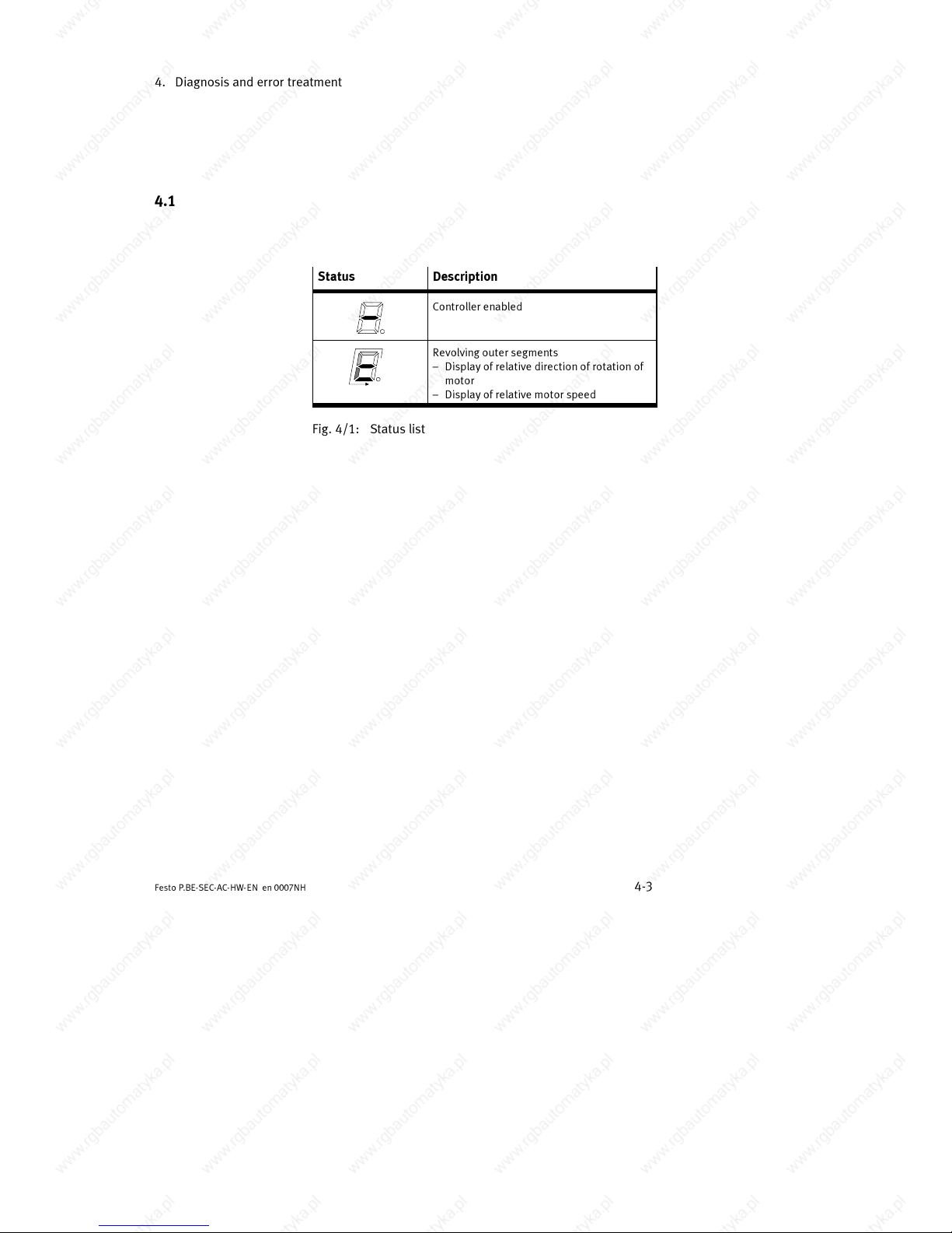
Status Description
Controller enabled
Revolving outer segments
– Display of relative direction of rotation of
motor
– Display of relative motor speed
Fig. 4/1: Status list
Page 70
4. Diagnosis and error treatment
4-4
Festo P.BE-SEC- AC-HW-EN en 0007NH
4.2 Error messages of the SEC-AC
Caution
S Switch off the power supply before star ting error treat-
ment.
The SEC-AC possesses an error memory for saving and dis-
playing even short error signals, e.g. overcurrent. Errors can-
not be reset automatically by the SEC-AC. They must be
quitted by the user by means of the reset button above the
7-segment display.
All errors which occur are shown on the 7-segment dispay.
The flashing two-figure error codes clearly indicate the type of
error. If there are several errrors at the same time, the error
with the lowest code will be displayed. The following table
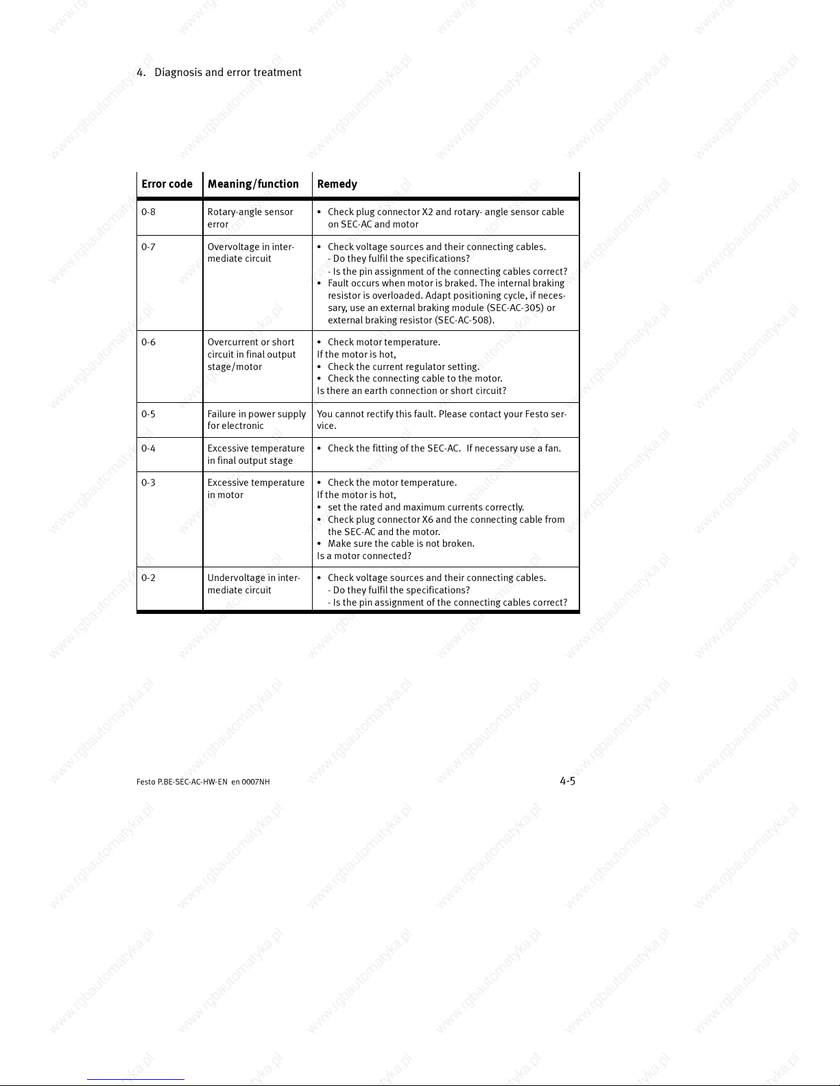
lists the error messages which can be displayed on the
SEC-AC.
Page 71
4. Diagnosis and error treatment
4-5
Festo P .BE-SEC-AC-HW- EN e n 0007NH
Error code Meaning/function Remedy
0-8 Rotary-angle sensor
error
S Check plug connector X2 and rotary- angle sensor cable
on SEC-AC and motor
0-7 Overvoltage in inter-
mediate circuit
S Check voltage sources and their connecting cables.
- Do they fulfil the specifications?
- Is the pin assignment of the connecting cables correct?
S Fault occurs when motor is braked. The internal braking
resistor is overloaded. Adapt positioning cycle, if neces-
sary, use an external braking module (SEC-AC-305) or
external braking resistor (SEC-AC-508).
0-6 Overcurrent or short
circuit in final output
stage/motor
S Check motor temperature.
If the motor is hot,
S Check the current regulator setting.
S Check the connecting cable to the motor.
Is there an earth connection or short circuit?
0-5 Failure in power supply
for electronic
You cannot rectif y this fault. Please contact your Festo ser-
vice.
0-4 Excessive temperature
in final output stage
S Check the fitt ing of the SEC-AC. If necessary use a fan.
0-3 Excessive temperature
in motor
S Check the motor temperature.
If the motor is hot,
S set the rated and maximum currents correctly.
S Check plug connector X6 and the connecting cable from
the SEC-AC and the motor.
S Make sure the cable is not broken.
Is a motor connected?
0-2 Undervoltage in inter-
mediate circuit
S Check voltage sources and their connecting cables.
- Do they fulfil the specifications?
- Is the pin assignment of the connecting cables correct?
Page 72
4. Diagnosis and error treatment
4-6
Festo P.BE-SEC- AC-HW-EN en 0007NH
Please note
If error 0-3 occurs, it may be that the motor does not pos-
sess a temperature sensor. In this case the relevant input
on plug connector X6 must be short-circuited.
RES button Each error message will only be deleted when the cause of
the error is rectified and when the error is subsequently
quitted. In order to quit an error, press the RES button.
Please note
Please note that all the parameter modifications, which
you have carried out, will be lost when you press the RES
button, if they have not been saved in the FLASH memory.
When an error has been rectified and quitted, the next error
code will be displayed.
Page 73

Technical Appendix
A-1Festo P .BE-SEC-AC-HW- EN e n 0007NH
Appendix A
Page 74

A. Technical Appendix
A-2
Festo P.BE-SEC- AC-HW-EN en 0007NH
Contents
A.1 ANPASSEN! Technische Daten Feldbusknoten CP FB13-E A-3...............
A.2 Stichwortverzeichnis A-5............................................
Page 75
A. Technical Appendix
A-3
Festo P .BE-SEC-AC-HW- EN e n 0007NH
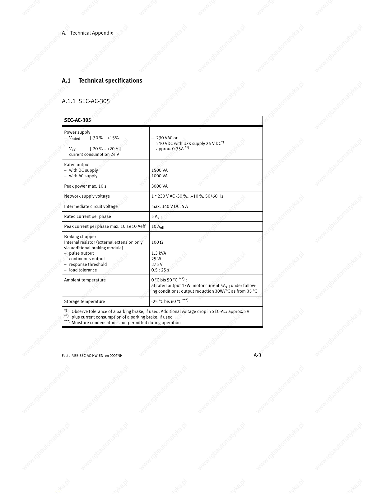
A.1 Technical specifications
A.1.1 SEC-AC-305
SEC-AC-305
Power supply
– V
rated
[-30 % .. +15%]
– V
CC
[-20 % .. +20 %]
current co nsumption 24 V
– 230 VAC or
310 VDC with UZK supply 24 V DC
*)
– approx. 0.35A
**)
Rated output
– with DC supply
– with AC supply
1500 VA
1000 VA
Peak power max. 10 s 3000 VA
Network supply voltage 1 * 230 V AC -30 %...+10 %, 50/60 Hz
Intermediate circuit voltage max. 340 V DC, 5 A
Rated current pe r phase 5A
eff
Peak curre nt per phase max. 10 s∆10 Aeff 10 A
eff
Braking chopper
Internalresistor (external extensiononly
via additional braking module)
– pulse output
– continuous output
– response threshold
– load tolerance
100 W
1,3 kVA
25 W
375 V
0.5 : 25 s
Ambient temperature 0 °Cbis50°C
***)
:
at rated output 1kW; motor current 5A
eff
under follow-
ing conditions: output reduction 30W/°Casfrom35°C
Storage temperature -25 °Cbis60°C
***)
*)
Observe tolerance of a parking brake, if used. Additional voltage drop in SEC-AC: approx. 2V
**)
plus current consumption of a parking brake, if used
***)
Moisture condensat on is not permitted during operation
Page 76
A. Technical Appendix
A-4
Festo P.BE-SEC- AC-HW-EN en 0007NH
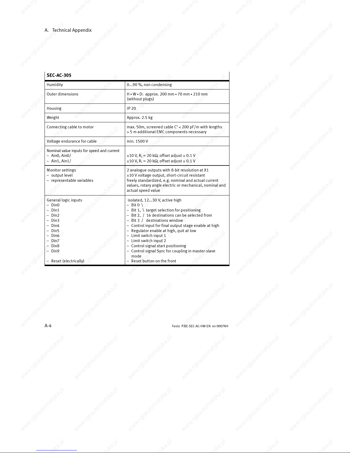
SEC-AC-305
Humidity 0...90 %, non condensing
Outer dime nsions H S W S D: approx. 200 mm S 70 mm S 210 mm
(without plugs)
Housing IP 20
Weight Approx. 2.5 kg
Connecting cable to motor max. 50m, screened cable C’ < 200 pF/m with lengths
> 5 m additional EMC components necessary
Voltage endurance for cable min. 1500 V
Nominal value inputs for speed and current
– Ain0, Ain0/
– Ain1, Ain1/
±10 V, R
i
= 20 kW, offset adjust ± 0.1 V
±10 V, R
i
= 20 kW, offset adjust ± 0.1 V
Monitor settings
– output level
– representable variables
2 analogue outputs with 8-bit resolution at X1
±10 V voltage output, short-circuit resistant
freely standardized, e.g. nominal and actual current
values, rotary angle electric or mechanical, nominal and
actual speed value
General logic inputs
– Din0
– Din1
– Din2
– Din3
– Din4
– Din5
– Din6
– Din7
– Din8
– Din9
– Reset (electrically)
isolated, 12...30 V, active high
–Bit 0 \
–Bit 1, \ target selection for positioning
–Bit 2, / 16 destinationscan be selected from
–Bit 3 / destinations window
– Control input for final output stage enable at high
– Regulator enable at high, quitatlow
– Limit switch input 1
– Limit switch input 2
– Control signal start positioning
– Control signal Sync for coupling in master-slave
mode
– Reset button on the front
Page 77
A. Technical Appendix
A-5
Festo P .BE-SEC-AC-HW- EN e n 0007NH
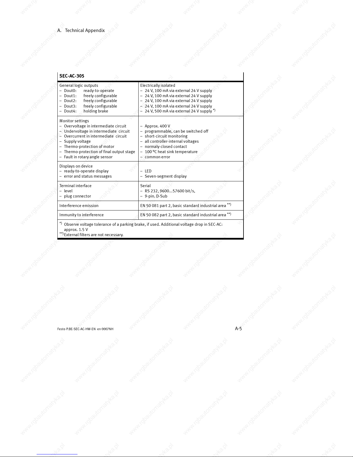
SEC-AC-305
General logic outputs
– Dout0: ready-to-operate
– Dout1: freely configurable
– Dout2: freely configurable
– Dout3: freely configurable
– Dout4: holding brake
Electrically isolated
– 24 V, 100 mA via external 24 V supply
– 24 V, 100 mA via external 24 V supply
– 24 V, 100 mA via external 24 V supply
– 24 V, 100 mA via external 24 V supply
– 24 V, 500 mA via external 24 V supply
*)
Monitor settings
– Overvoltage in intermediate circuit
– Undervoltage in intermediate circuit
– Overcurrent in intermediate circuit
– Supply voltage
– Thermo-protection of motor
– Thermo-protection of final output stage
– Fault in rot ary angle sensor
– Approx. 400 V
– programmable, can be switched off
– short-circuit monitoring
– all controller-internal voltages
– normaly-closedcontact
– 100 °C heat sink temperature
– common error
Displays on device
– ready-to-operate display
– error and status messages
– LED
– Seven-segment display
Terminal interface
– level
– plug connector
Serial
– RS 232, 9600...57600 bit/s,
–9-pin. D-Sub
Interference emission EN 50 081 part 2, basic standard industrialarea
**)
Immunity to interference EN 50 082 part 2, basic standard industrialarea
**)
*)
Observe voltage tolerance of a parking brake, if used. Additional voltage drop in SEC-AC:
approx. 1.5 V
**)
External filters are not necessary.
Page 78
A. Technical Appendix
A-6
Festo P.BE-SEC- AC-HW-EN en 0007NH
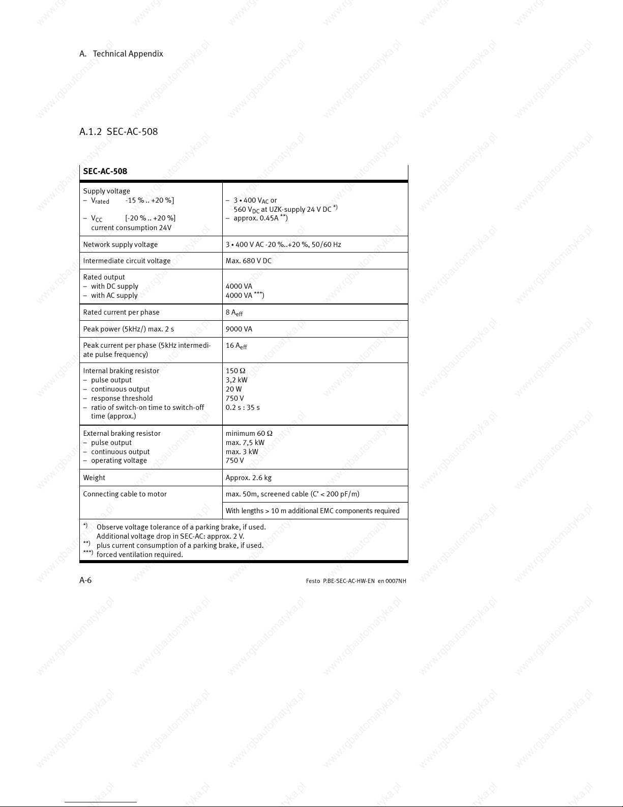
A.1.2 SEC-AC-508
SEC-AC-508
Supply voltage
– V
rated
-15%..+20%]
– V
CC
[-20 % .. +20 %]
current co nsumption 24V
– 3 S 400 VACor
560 V
DC
at UZK-supply 24 V DC
*)
– approx. 0.45A**)
Network supply voltage 3 S 400 V AC -20 %..+20 %, 50/60 Hz
Intermediate circuit voltage Max. 680 V DC
Rated output
– with DC supply
– with AC supply
4000 VA
4000 VA
***
)
Rated current pe r phase 8A
eff
Peak power (5kHz/) max. 2 s 9000 VA
Peak current per phase (5kHz intermedi-
ate pulse fre q uency)
16 A
eff
Internalbraking resistor
– pulse output
– continuous output
– response threshold
– ratio of switch-ontime to switch-off
time ( approx.)
150 W
3,2 kW
20 W
750 V
0.2 s : 35 s
External braking resistor
– pulse output
– continuous output
– operating volta ge
minimum 60 W
max. 7,5 kW
max. 3 kW
750 V
Weight Approx. 2.6 kg
Connecting cable to motor max. 50m, screened cable (C’ < 200 pF/m)
With lengths > 10 m additional EMC components required
*)
Observe voltage tolerance of a parking brake, if used.
Additional voltage drop in SEC-AC: approx. 2 V.
**)
plus current consumption of a parking brake, if used.
***)
forced ventilation required.
Page 79
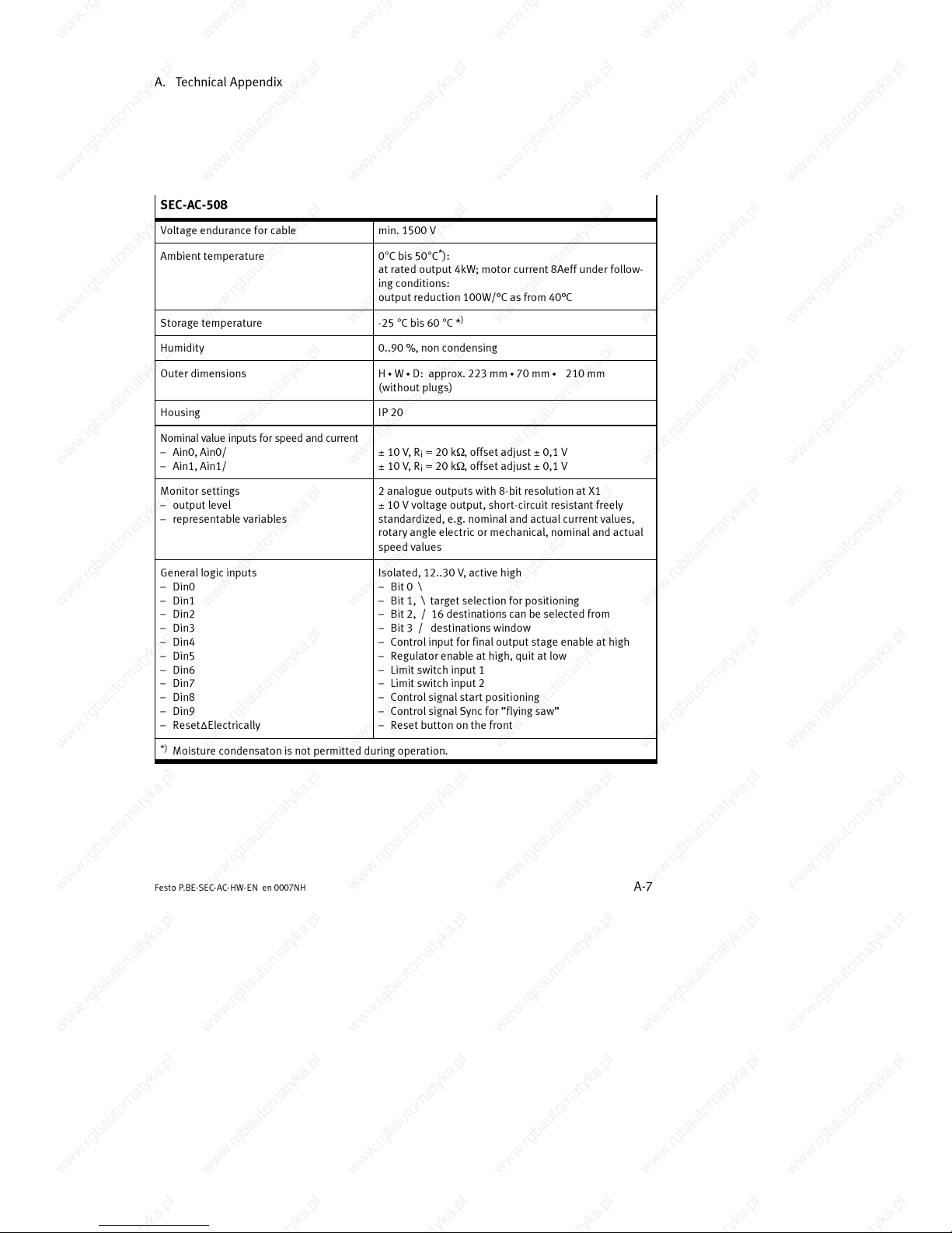
A. Technical Appendix
A-7
Festo P .BE-SEC-AC-HW- EN e n 0007NH
SEC-AC-508
Voltage endurance for cable min. 1500 V
Ambient temperature 0°Cbis50°C*):
at rated output 4kW; motor current 8Aeff under follow-
ing conditions:
output reduction 100W/°Casfrom40°C
Storage temperature -25 °Cbis60°C *
)
Humidity 0..90 %, non condensing
Outer dime nsions H S W S D: approx. 223 mm S 70 mm S 210 mm
(without plugs)
Housing IP 20
Nominal value inputs for speed and current
– Ain0, Ain0/
– Ain1, Ain1/
± 10 V,R
i
= 20 kW,offsetadjust ± 0,1 V
± 10 V,R
i
= 20 kW,offsetadjust ± 0,1 V
Monitor settings
– output level
– representable variables
2 analogue outputs with 8-bit resolution at X1
± 10 V voltage output, short-circuit resistant freely
standardized, e.g. nominal and actual current values,
rotary angle electric or mechanical, nominal and actual
speed values
General logic inputs
– Din0
– Din1
– Din2
– Din3
– Din4
– Din5
– Din6
– Din7
– Din8
– Din9
– Reset∆Electrically
Isolated, 12..30 V, active high
–Bit 0 \
–Bit 1, \ target selection for positioning
–Bit 2, / 16 destinationscan be selected from
–Bit 3 / destinations window
– Control input for final output stage enable at high
– Regulator enable at high, quitatlow
– Limit switch input 1
– Limit switch input 2
– Control signal start positioning
– Control signal Sync for ”flying saw”
– Reset button on the front
*)
Moisture condensat on is not permitted during operation.
Page 80
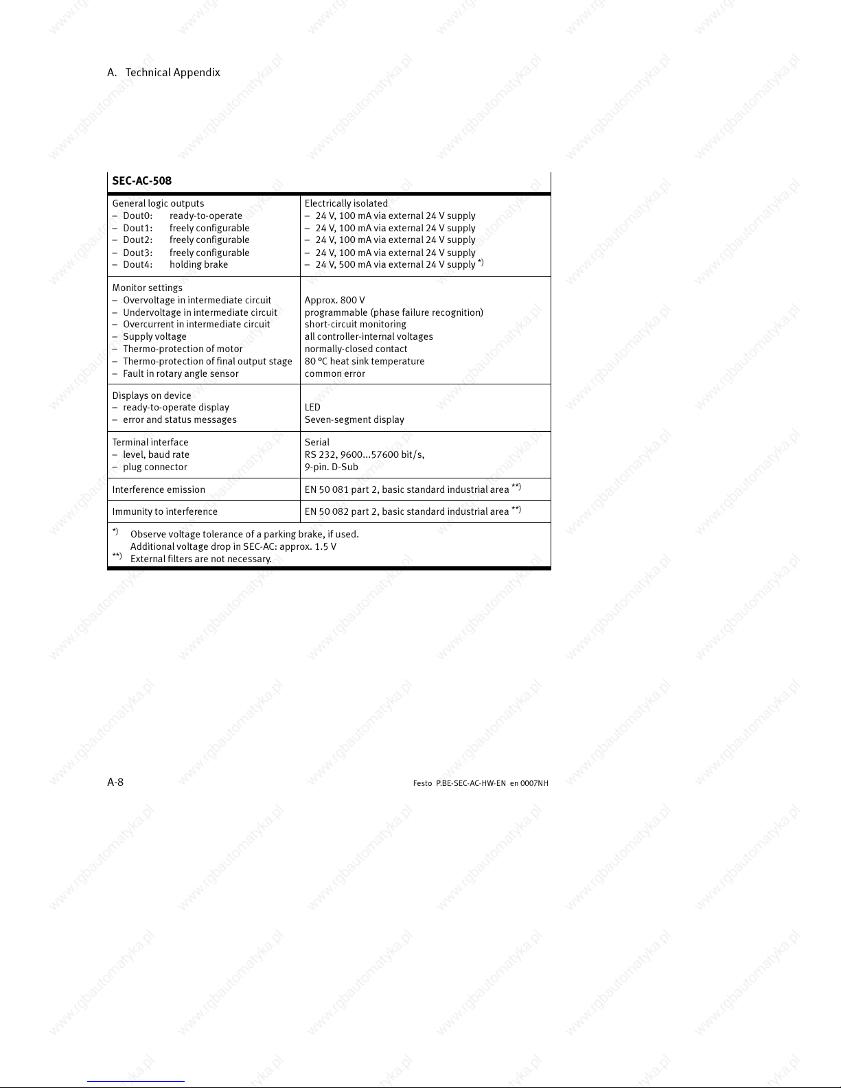
A. Technical Appendix
A-8
Festo P.BE-SEC- AC-HW-EN en 0007NH
SEC-AC-508
General logic outputs
– Dout0: ready-to-operate
– Dout1: freely configurable
– Dout2: freely configurable
– Dout3: freely configurable
– Dout4: holding brake
Electrically isolated
– 24 V, 100 mA via external 24 V supply
– 24 V, 100 mA via external 24 V supply
– 24 V, 100 mA via external 24 V supply
– 24 V, 100 mA via external 24 V supply
– 24 V, 500 mA via external 24 V supply
*)
Monitor settings
– Overvoltage in intermediate circuit
– Undervoltage in intermediate circuit
– Overcurrent in intermediate circuit
– Supply voltage
– Thermo-protection of motor
– Thermo-protection of final output stage
– Fault in rot ary angle sensor
Approx. 800 V
programmable (phase failure recognition)
short-circuit monitoring
all controller-internal voltages
normally-closed conta ct
80 °C heat sink temperature
common error
Displays on device
– ready-to-operate display
– error and status messages
LED
Seven-segment display
Terminal interface
– level, baud rate
– plug connector
Serial
RS 232, 9600...57600 bit/s,
9-pin. D-Sub
Interference emission EN 50 081 part 2, basic standard industrialarea
**)
Immunity to interference EN 50 082 part 2, basic standard industrialarea
**)
*)
Observe voltage tolerance of a parking brake, if used.
Additional voltage drop in SEC-AC: approx. 1.5 V
**)
External filters are not necessary.
Page 81
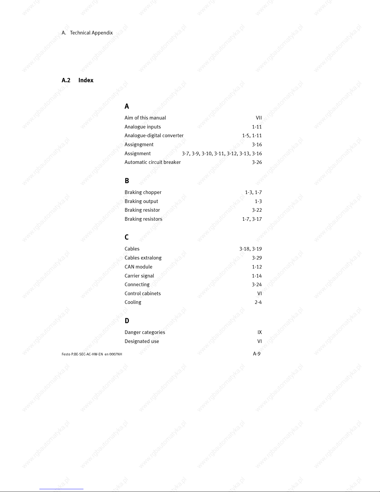
A. Technical Appendix
A-9
Festo P .BE-SEC-AC-HW- EN e n 0007NH
A.2 Index
A
Aim of this manual VII
Analogue inputs 1-11
Analogue-digital converter 1-5, 1-11
Assigngment 3-16
Assignment 3-7, 3-9, 3-10, 3-11, 3-12, 3-13, 3-16
Automatic circuit breaker 3-26
B
Braking chopper 1-3, 1-7
Braking output 1-3
Braking resistor 3-22
Braking resistors 1-7, 3-17
C
Cables 3-18, 3-19
Cables extralong 3-29
CAN module 1-12
Carrier signal 1-14
Connecting 3-24
Control cabinets VI
Cooling 2-4
D
Danger categories IX
Designated use VI
Page 82
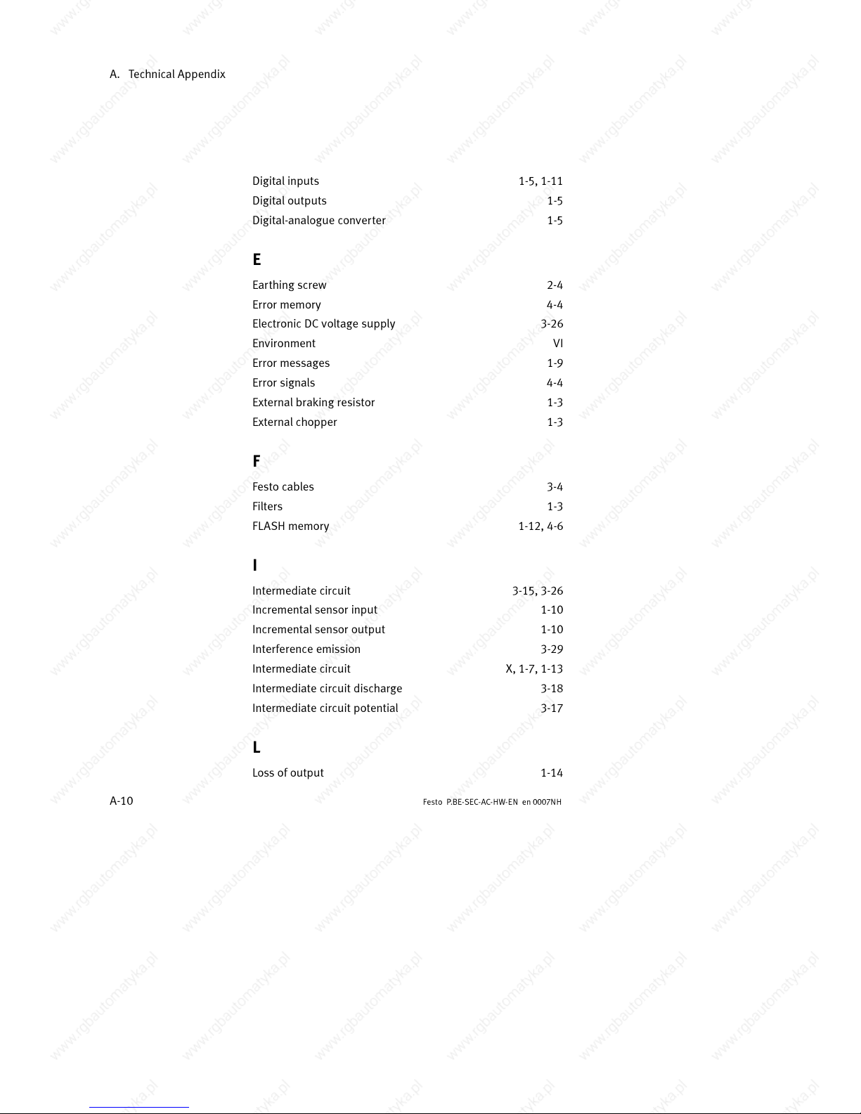
A. Technical Appendix
A-10
Festo P.BE-SEC- AC-HW-EN en 0007NH
Digital inputs 1-5, 1-11
Digital outputs 1-5
Digital-analogue converter 1-5
E
Earthing screw 2-4
Error memory 4-4
Electronic DC voltage supply 3-26
Environment VI
Error messages 1-9
Error signals 4-4
External braking resistor 1-3
External chopper 1-3
F
Festo cables 3-4
Filters 1-3
FLASH memory 1-12, 4-6
I
Intermediate circuit 3-15, 3-26
Incremental sensor input 1-10
Incremental sensor output 1-10
Interference emission 3-29
Intermediate circuit X, 1-7, 1-13
Intermediate circuit discharge 3-18
Intermediate circuit potential 3-17
L
Loss of output 1-14
Page 83
A. Technical Appendix
A-11
Festo P .BE-SEC-AC-HW- EN e n 0007NH
M
Maximum current 1-13
Memory ranges 1-12
Micro controller 1-5
Monitor 1-13
Monitoring function 1-8
Motor phases 3-23
Motor temperature 1-14
N
Networking of several regulators 1-10
O
Operating states 1-9
Operating earth 3-26
Operating earth 3-27
Operating mode 1-9
Operating voltage range 1-13
P
Parametrizing program 1-12
Parking brake 1-14
Phase sequences 3-23
Pictogram IX
Pictograms XI
Plug 3-5
Positioning destinations 1-11
Power supply 3-15, 3-23
Position regulator 1-4
Page 84
A. Technical Appendix
A-12
Festo P.BE-SEC- AC-HW-EN en 0007NH
R
RAM 1-12
Reference point 1-11
RES button 4-6
Reset button 1-13, 4-4
Resolver 1-10
Resolver plug 3-22
Rotary transducer evaluating unit 1-10
S
Safety instructions X
Sample input 1-11
Sensors 1-8, 1-13
Serial interface 1-10, 3-21
Service VIII
Signal distortions 1-6
Single-phase 1-6
Speed 1-4
Star-shaped 1-6
Star point 3-27
Symbols VII
T
Tar get group VI I
Technological extensions 1-3
Temperature 1-13
Temperature sensor 3-14
Tex t markings X I
Three-phase network 1-6
Page 85
A. Technical Appendix
A-13
Festo P .BE-SEC-AC-HW- EN e n 0007NH
Tor que 1-4
Tracer signal 1-14
Trade marks VIII
U
Use of the SEC-AC VI
User instructions IX
V
Vew 2-5, 2-6, 2-7
Voltage supply 3-15
W
Watchdog timer 1-5
Page 86
Nutzungsvereinbarungen für ”Elektronische Dokumentation”
I. Schutzrechte und N utzungsumfang
Dieses Produkt beinhaltet Dokumentation zu Festo-Produkten auf einem
Datenträger. Deren Gesamtheit wird im folgenden mit ”Elektronische
Dokumentation” bezeichnet. Festo od er Dritte haben Schutzrec hte an dieser
Elektronischen Dokumentation. Soweit die Rechte Dritten zustehen, hat
Festo entsprechende Nutzungsrechte. Festo gestattet dem Verwender die
Nutzung unter den folge nden Voraussetzungen:
1. Nutzungs umfang
a) Der Verwe nder der Elektroni schen Dokumentation i st berechtig t, diese für
eigene, aussch ließlich betriebsinterne Zwecke auf b eliebig viele n Maschi-
nen innerhalb seines Betriebsgeländes (Einsatzort) zu nutzen. Dieses
Nutzungsrecht umfaßt ausschließlich das Recht, die Elektronische
Dokumentation auf den am Einsatzort eingesetzten Zentraleinheiten
(Maschinen) abzuspiele n.
b) Die Elektronische Dokumentation darf am Einsatzort des Verwenders in
beliebiger Zahl ko piert, verwahrt und gedruckt werde n, sofern dies e Kopie
vollständig mit diesen Nutzungsvereinbarungen und sonstigen Benutzer-
hinweisen kopiert, ve rwahrt bzw. gedruckt wird.
c) Mit Ausnahme des Festo-Logos is t der Verwender berechtigt, Bilde r und
Texte der Elektronischen Dokumentation zur Erstellung eigener Maschi-
nen- und Anlagendokumentation zu verwenden. Die Verwendung des
Festo-Logos bedarf der schriftlichen Genehmigung von Festo. Für die
Übereinstimmung genutzter Bilder und Texte mit der Maschine/Anlage
bzw. dem Produkt ist der Verwe nder selbst verantwortlich.
d) Eine wei tergehende Nutzung, insbesondere das Vervi elfältigen für andere
Zwecke sowie die Weitergabe von Kopien und Ausdrucken an Dritte
außerhalb der Regelung in Ziffer 3, sowie jede Bearbeitung oder
andersartige Verw endung, ist nicht zulässig.
2. Copyright Vermerk
Jedes ”Elektronische Dokument” enthält einen Copyright Vermerk. In jede
Kopie und jeden Ausd ruck muß dieser Vermerk übernommen werden.
3. Übertragung der Nutzun gsbefugnis
Der Verwender kann seine Nutzungsbefugnis in dem Umfang und mit den
Beschränkungen d er Bedin gungen ge mäß Ziffer 1 und 2 insgesamt auf einen
Dritten für dessen ausschließlich betriebsinterne Zwecke übertragen. Auf
diese Nutzungsvereinbarungen ist der Dritte ausdrücklich hinzuweisen. Mit
der Übertragung erlöschen alle Nutzungsrechte des Veräußerers, und zwar
auch an den Kopien und Ausdrucken. Soweit diese dem Dritten nicht
überlassen werden , sind sie zu vernichten . Andere in diese r Elektroni schen
Dokumentation etwa entha ltene Bedingun gen anderer Herstelle r gelten nicht.
Nutzungsvereinbarungen
9901 b I
Page 87
II. Export der Elektron ischen Dokumentation
Der Lizenz-Nehmer muß beim Export der E lektronischen Dokumentation die
Ausfuhrbestimmungen d er Bundesrepublik Deutschl and und des Lan des des
Erwerbs beachten.
III. Gewährle istung
1. Festo-Produkte werden hard- und software-technisch weiterentwickelt.
Der Hard- und g gf. der Softwa re-Stand des P rodukts ist dem Typens child
des Produkts zu entnehmen. Festo gewährleistet nicht, daß die
Elektronische Dokumentation mit jedem Hard- und Software-Stand des
Produkts übereinstimmt. Maßgeblich für den übereinstimmenden Hard-
und Software-Stand des Produkts ist die dem Produkt beiliegende
gedruckte Dokumentation von Festo.
2. Die in dieser Elektronischen Dokumentation enthaltenen Informationen
können von Festo ohne Vorank ündigungen geändert werden, und stellen
keine Verpflichtun g seitens Festo dar.
IV. Haftung-/Haftungsbeschränkunge n
1. Festo stellt diese Elektronische Dokumentation zur Verfügung, um den
Verwender bei der Erstel lung seiner Maschinen- und Anlagen dokumenta-
tion zu unterstützen. F esto gewährleistet jedoch nicht, daß die geli eferte
Elektronische Dokumentation mit dem vom Verwende r genutzen Produkt
übereinstimmt. Letzteres gilt insbeson dere bei auszugswei sem Gebrauch
für eigene Dokumentationen des Verwe nders.
2. Festo haftet ferner nicht für mangelnden wirtschaftlichen Erfolg oder für
Schäden oder Ansprüc he Dritter, mit Ausnahme von Ansprüchen aus der
Verletzung vo n Schutzrechten Dritter, die die Nutzung der elektronische n
Dokumentation betreffen .
3. Die Haftungsbeschränkun gen nach Absatz 1. und 2. ge lten nicht, soweit
in Fällen vo n Vorsatz oder grobe r Fahrlässigkeit oder Fehlen zugesicher-
ter Eigenschaften eine zwingende H aftung besteht. In einem solchen Fall
ist die Haftung von Festo auf denjenigen Schaden begrenzt, der für Festo
nach der Kenntn is der konkreten Umstände erkennbar wa r.
V. Sicherheitsrichtlinien/D okumentation
Gewährleistungs- und Haftungsanspruch nach Maßgabe der vorstehenden
Regelungen (Ziff. III. u. IV) sind nur gegeben, wenn der Anwender die
Sicherheitsric htlinien de r Dokumentation i m Zusammenhang mit der Nutzung
der Maschine und deren Sicherheitsrichtlinien beachtet hat. Für die
Kompatibilität der Elektronischen Dokumentation mit dem vom Anwender
genutzten Produkt ist der Anwender se lbst verantwortlich.
Nutzungsvereinbarungen
II
9901 b
 Loading...