

Page 1
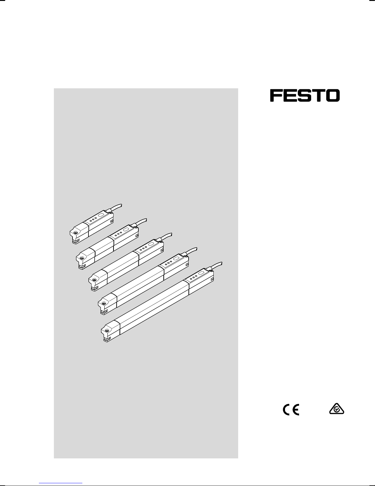
Position transmitter
SDAT-MHS
en Manual
8080048
2017-11f
[8080050]
Page 2
SDAT-MHS
Translation of the original instructions
SDAT-MHS-EN
This documentation refers to the following version: From Revision R04.
Identification of dangers and instructions on how to avoid them:
Warning
Dangers which can lead to death or serious injuries.
Other symbols:
Note
Material damage or loss of function.
Text designations:
Activities which can be carried out in any sequence.
1. Activities which should be carried out in the specified sequence.
– General lists.
2 Festo – SDAT-MHS – 2017-11f
Page 3

SDAT-MHS
1 Product description 5.......................................................
1.1 Overview 5................................................................
1.2 Characteristics 5...........................................................
2 Function and application 6...................................................
2.1 Analogue output function 7...................................................
2.2 Switching functions and switching logic 8........................................
2.2.1 Window comparator 8...............................................
2.2.2 Cylinder switch function 9............................................
2.2.3 Hysteresis comparator 9.............................................
2.2.4 Normally open (NO) and normally closed (NC) contacts 9...................
2.3 Switching output operating mode (SIO) 10........................................
2.4 IO-Link operating mode 10....................................................
3 Requirements for product use 11...............................................
4 Installation 13..............................................................
4.1 Electrical 13................................................................
4.2 Mechanical 14..............................................................
5 Commissioning 15...........................................................
5.1 Set set-up mode 15..........................................................
5.2 Scale analogue signal 15......................................................
5.3 Program switching output 16..................................................
5.3.1 Set window comparator 16............................................
5.3.2 Set cylinder switch function 17.........................................
5.3.3 Set hysteresis comparator 18..........................................
5.3.4 Invert switching logic (NO or NC) 18.....................................
5.4 Block / unblock operating key 19...............................................
5.5 Program IO-Link output 19.....................................................
6 Operation 20...............................................................
6.1 Magnetic direction detection and correction 20....................................
6.2 LED indicators 20............................................................
6.3 Reset position transmitter to factory setting 21....................................
7 Disassembly 22.............................................................
Festo – SDAT-MHS – 2017-11f English 3
Page 4

SDAT-MHS
8 Fault clearance 22...........................................................
8.1 Diagnostics via LED 22........................................................
8.2 General malfunctions 23......................................................
9 Accessories 23..............................................................
10 Technical data 24............................................................
10.1 General 24.................................................................
10.2 IO-Link 25..................................................................
10.3 I-Port 30...................................................................
11 Appendix 31................................................................
4 Festo – SDAT-MHS – 2017-11f English
Page 5
SDAT-MHS
1 Product description
For all available product documentation è www.festo.com/pk
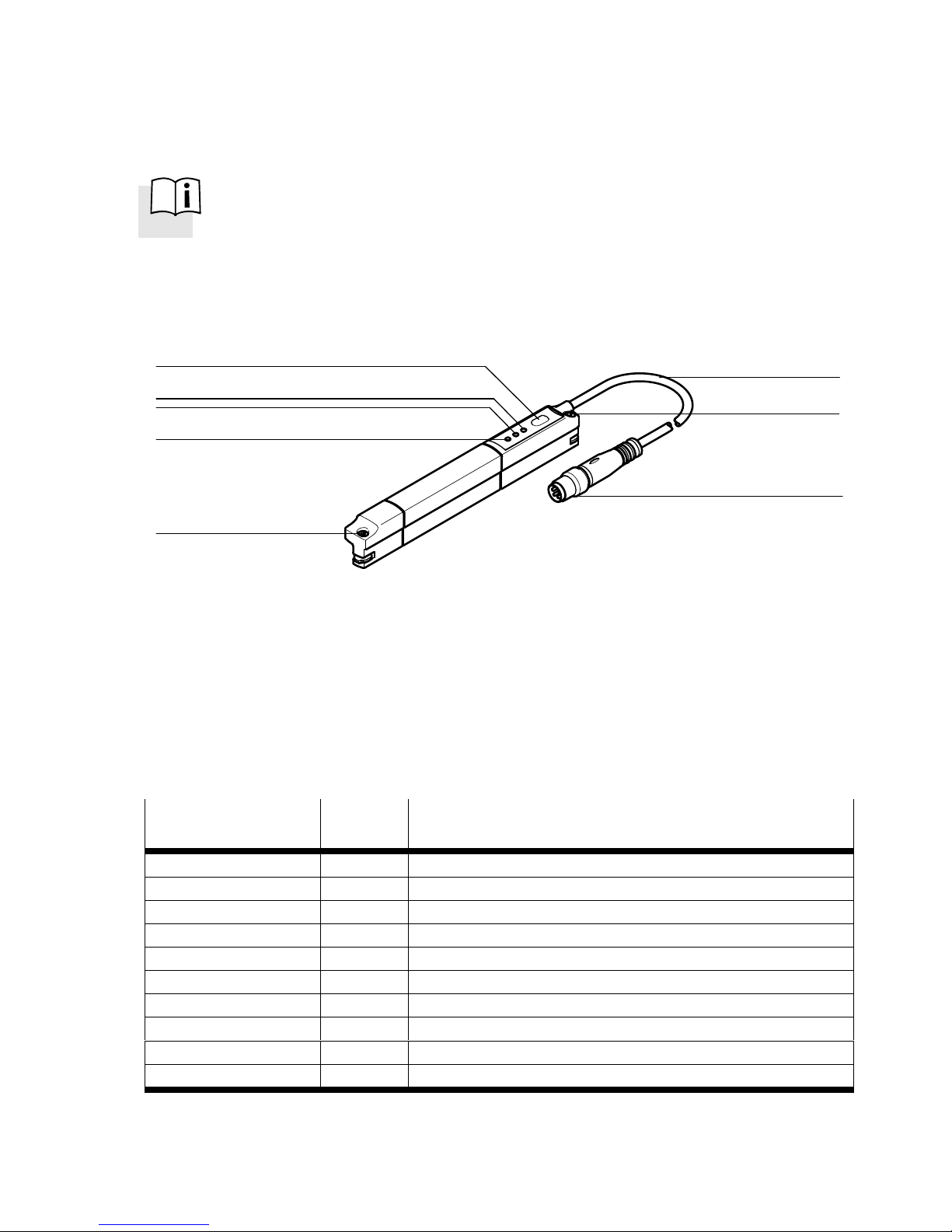
1.1 Overview
7
6
5
4
2
1 Connecting cable
2 Mounting screw
3 Plug M8, rotatable
4 Red LED: Status display
Fig. 1 Control sections and connections
1.2 Characteristics
1
2
3
5 Green LED: Ready status display
6 Yellow LED: Switching status display
7 Operating key
Feature
Position transmitter SDATMounting M Insertable in slot
Sensing HS- Hall sensor
Sensing range Mxx- Range in mm, xx = 50/80/100/125/160
Operating voltage 1 24 V DC
Display L- LED
Electrical output SA- PNP or IO-Link and analogue output 4…20 mA
Cable characteristic E- Energy chain + robot
Cable length 0.3- Cable length 0.3 m
Electrical connection M8D M8 rotatable (threaded sleeve)
Tab. 1 Overview of variants
Festo – SDAT-MHS – 2017-11f English 5
Order
code
Specification
Page 6

SDAT-MHS
2 Function and application
The position transmitter SDAT-MHS is intended for contactless recording of the piston position of mag
netically detectable drives and grippers. It is appropriate for use with Festo drives with T-slot (profile
slot 8) as well as round cylinders and tie-rod cylinders with mounting kits.
Use the SDAT-MHS only for the suitable drives and grippers from Festo è www.festo.com/
catalogue.
The position transmitter SDAT-MHS records the magnetic field of the piston magnet and continuously
senses the piston movement in the sensing range.
Available output signals include:
– analogue current signal (4…20 mA)
– programmable switching output (24 V),
– IO-Link communication mode (è Chapter 2.3).
6 Festo – SDAT-MHS – 2017-11f English
Page 7
SDAT-MHS
2.1 Analogue output function
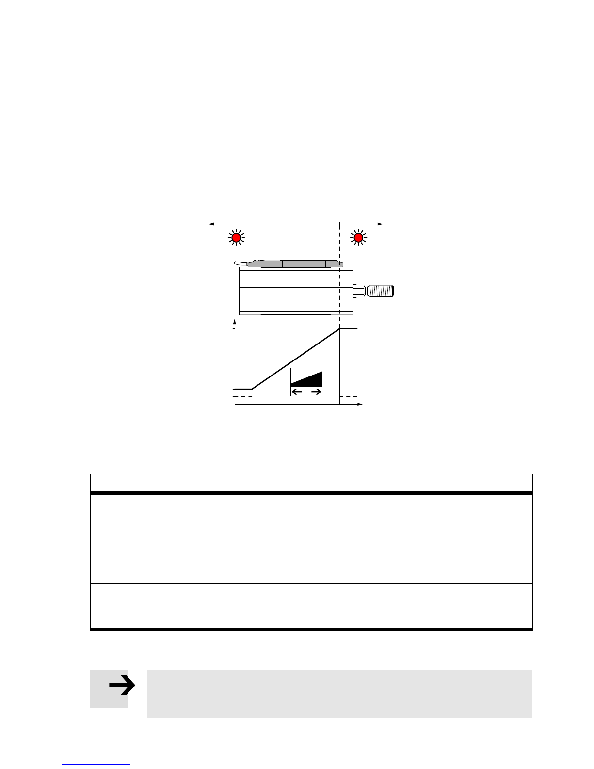
The analogue output provides a path-proportional output signal 4…20 mA in the sensing range of the
piston stroke.
– The analogue output signal can be scaled.
– The direction of increase of the analogue output signal can be inverted.
– In the switching output operating mode, the analogue position signal is made available parallel and
independent of the position value output of the switching output.
– The analogue output is switched off in the operating mode IO-Link.
AB C
20 mA
4 mA
2 mA
0 mm x mm
x = Maximum length of the sensing range (type-dependent)
Fig. 2 Characteristic curve, analogue output
Signal
Description Area
0 mA – IO-Link operation
– error (e.g. broken cable, parameter error)
2 mA – piston outside of the sensing range after the operating voltage is
switched on
4 mA – the piston has left the sensing range in the direction of the falling
output current
>4 mA ... <20 mA – piston within the sensing range B
20 mA – the piston has left the sensing range in the direction of the rising
output current
1) Area è Fig. 2, Area A and C: Red LED illuminated
Tab. 2 Output signal, analogue output
1)
A, C
A
C
Note
With active IO link communications, the analog output is switched off
(output current = 0 mA).
Festo – SDAT-MHS – 2017-11f English 7
Page 8
SDAT-MHS
Scaling of the analogue signal
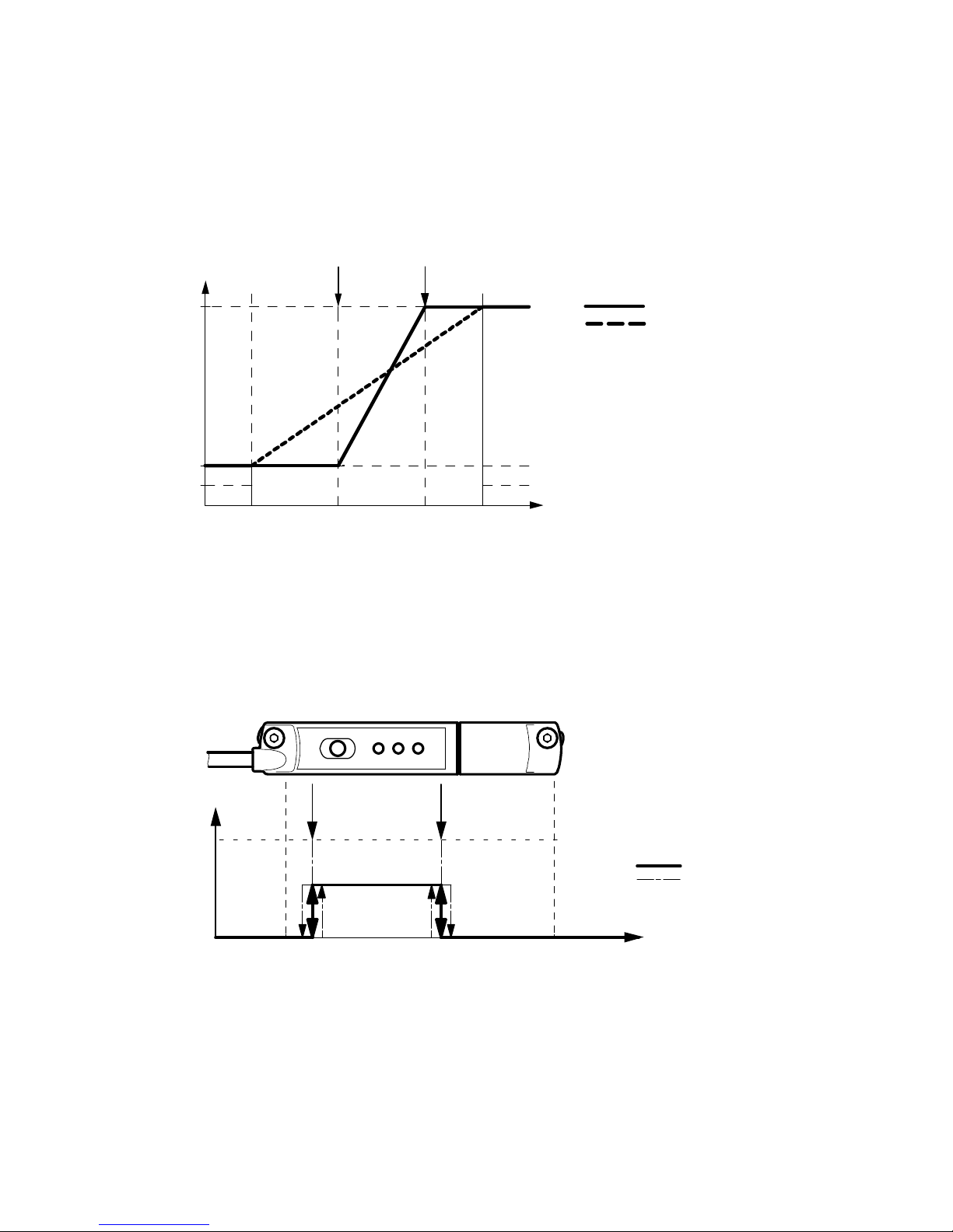
The analogue output signal 4…20 mA is assigned as standard to the complete sensing range. If only a
part of the sensing range is used, the analogue value output can be scaled to the sensing range actually
used. Resolution and repetition accuracy are not improved through scaling.
12
20 mA
4 mA
2 mA
0 mm 60 mm 120 mm 160 mm
1 Teach point 1
2 Teach point 2
Fig. 3 Scaling of the analogue signal (example SDAT-MHS-M160)
2.2 Switching functions and switching logic
2.2.1 Window comparator
Analogue signal
Scaled
Not scaled
12
OUT
1 Teach point 1
2 Teach point 2
Fig. 4 Window comparator
The teach points (1,2) are linked to the window comparator function.
– The position of the teach points determines the window width.
– Hysteresis is not selectable or preset.
8 Festo – SDAT-MHS – 2017-11f English
Switching travel
hysteresis
IN
Page 9
SDAT-MHS
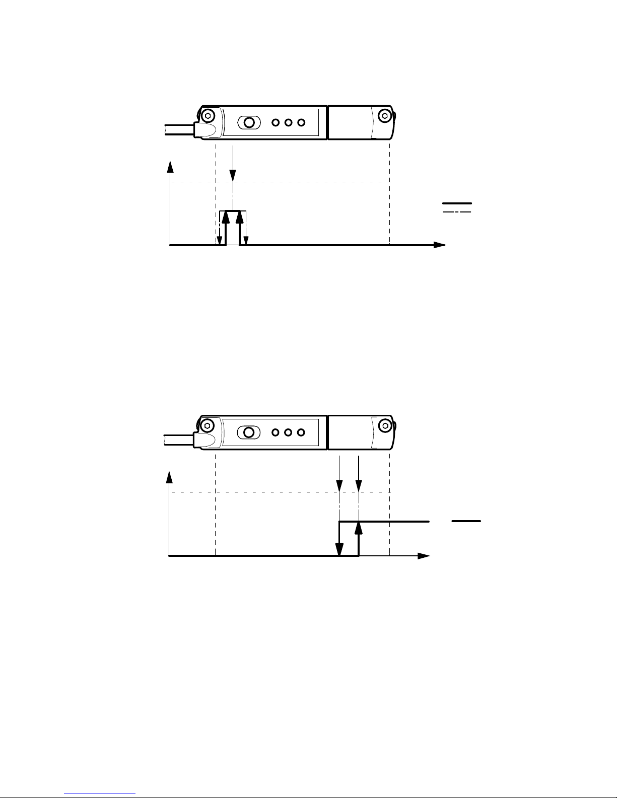
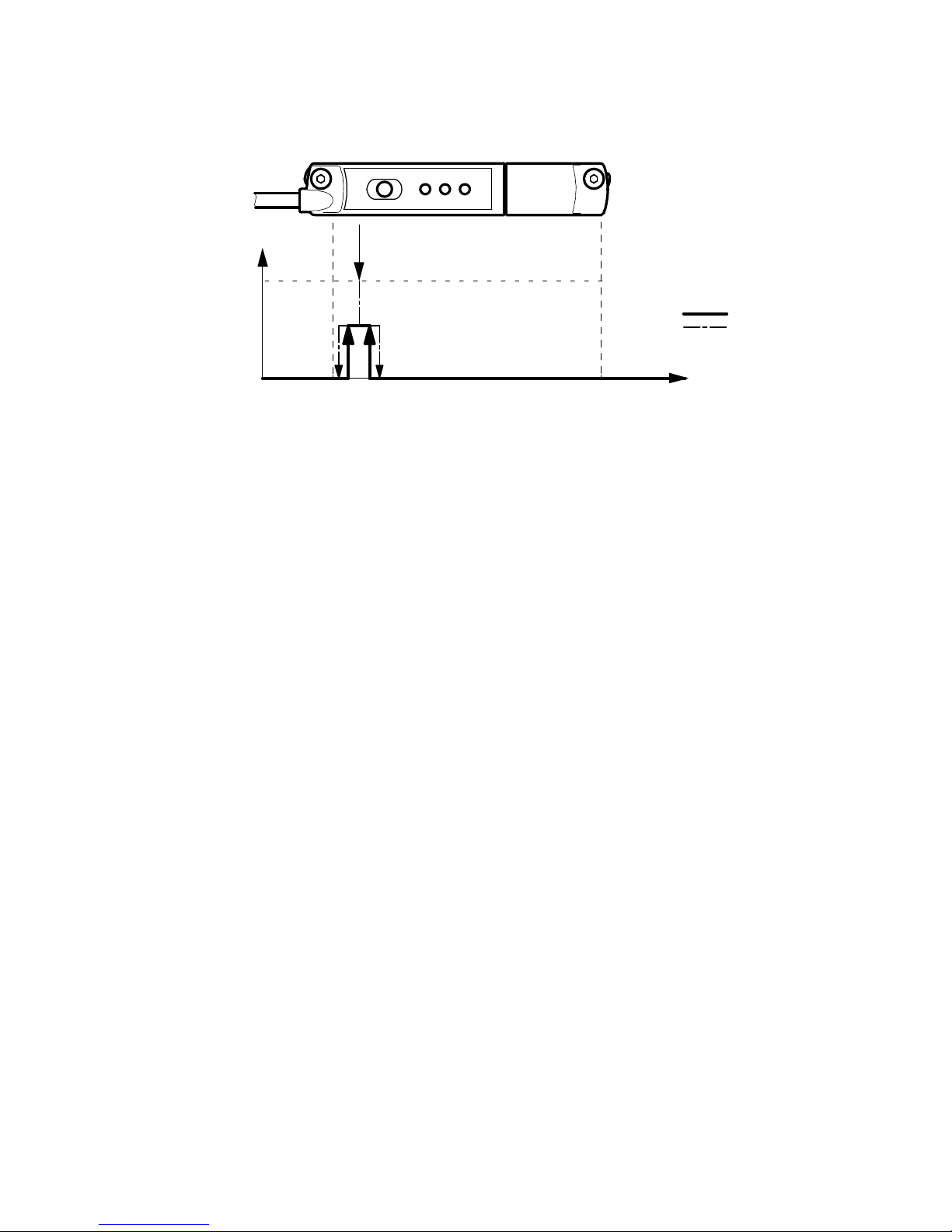
2.2.2 Cylinder switch function
1
OUT
Switching travel
hysteresis
IN
1 Teach point
Fig. 5 Cylinder switch function
The cylinder switch function consists of the switching travel and hysteresis. Hysteresis serves to sup
press switching signals in the event of fluctuations around the switching point.
– The teach value is the middle of the switching travel.
– Switching travel and hysteresis are not adjustable. For switching travel and hysteresis, values are
stored that correspond to a typical electronic cylinder switch in a typical drive.
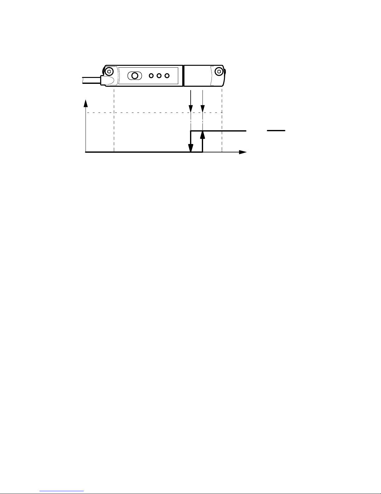
2.2.3 Hysteresis comparator
2
OUT
1
IN
1 Teach point 1
2 Teach point 2
Fig. 6 Hysteresis comparator
The teach points (1,2) are linked to the hysteresis comparator function.
– Teach point 1 (ON) is the switch-on point, teach point 2 (OFF) is the reset point.
– Teach point 2 establishes the size of the hysteresis.
Switching travel
2.2.4 Normally open (NO) and normally closed (NC) contacts
The switching logic normally open (NO) is set as standard. The function of the switching output is inver
ted through selection of the normally closed function (NC).
Festo – SDAT-MHS – 2017-11f English 9
Page 10

SDAT-MHS
2.3 Switching output operating mode (SIO)
If the IO-Link/switching output is operated as a switching output, only 1 binary channel can be pro
grammed. The switching output operating mode must be programmed actively via set-up mode (key)
(è Chapter 5.3).
– Either window comparator or cylinder switch function or hysteresis comparator programmable.
– Switching logic normally closed (NC) or normally open (NO) selectable.
– Programming via IO-Link protocol (channel BDC1) or operating key on the device.
– Display switching output ON: Yellow LED illuminated.
– Output signal 24 V DC (PNP).
Note
Even if the analogue output has been scaled, the switching output can still be pro
grammed over the entire sensing range.
2.4 IO-Link operating mode
In the IO-Link operating mode, programmed switching signals and the continuous position values (digit
ally coded analogue values) are transferred.
– There are 4 binary channels available, which can be programmed individually as window comparator
or cylinder switch or hysteresis comparator.
– The continuous position values are always transferred parallel and independent of the position
value output of the binary channels.
– Each channel is adjustable as normally closed (NC) or normally open (NO).
– Data transmission is serially and digitally coded in the IO-Link protocol.
– Process data: 12 bit for position data and 4 bit for binary channels (è Chapter 10).
– Usage of unscreened standard cables of up to 20 m in length is possible.
– Device description file IODD for every device length è www.festo.com/sp.
– Parameters and functions in accordance with Smart-Sensor profile.
– Support of optional functions Block Parameterisation and Data Storage.
– Display IO-Link operation: Green LED flashes (1 Hz).
– Inversion of direction of process data values (PDV).
PDV is minimally (standard) or maximally (inverted) at the cable end of the sensor.
10 Festo – SDAT-MHS – 2017-11f English
Page 11
SDAT-MHS
3 Requirements for product use
Use the product in its original status, without any unauthorised product modifications.
Use the SDAT-MHS only for the suitable drives from Festo (è www.festo.com/catalogue).
Avoid having magnetic bodies near the position transmitter. These could influence the magnetic
field and thereby the behaviour of the sensor.
Do not exceed the limit values (e.g. voltages, forces, temperatures).
Take into consideration the ambient conditions at the location of use.
This product can generate high frequency interference, which may make it necessary to implement
interference suppression measures in residential areas.
Observe the regulations which apply in your location (e.g. from trade associations or from national
institutions).
Remove all transport packaging. The material used in the packaging has been specifically chosen
for its recyclability (with the exception of the oil-impregnated paper which is residual waste).
Areas of application and approval by authorities
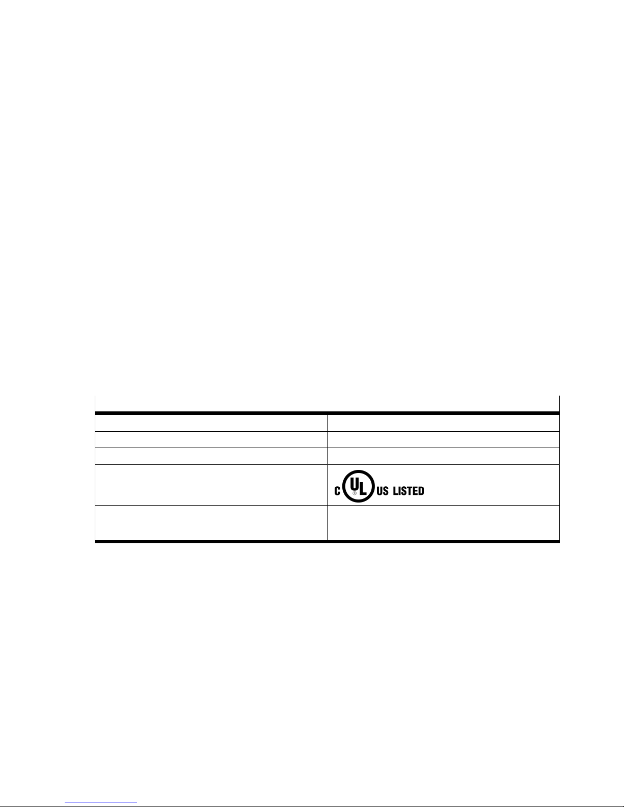
In connection with the UL marking on the product, the information of this section is applicable for com
pliance with the certification conditions of Underwriters Laboratories Inc. (UL) for the U.S.A. and
Canada. Observe the following remarks from UL:
UL approval information
Product category code NRKH, NRKH7
File number E232949
Considered standards UL 60947-1 and UL 60947-5-2, C22.2 No. 14-13
UL mark
Product category
Control Number
Ind. Cont. EQ.
(Industrial Control Equipment)
2MD1
Festo – SDAT-MHS – 2017-11f English 11
Page 12
SDAT-MHS
Only for connection to a NEC Class 2 supply.
Raccorder Uniquement a un circuit de Classe 2.
This device is intended to be used with a Class 2 power source or Class 2 transformer in accordance
with UL1310 or UL1585.
As an alternative a LV/C (Limited Voltage/Current) power source with one of the following properties
can be used:
– This device shall be used with a suitable isolating source such that the maximum open circuit
voltage potential available to the product is not more than 30 V DC and the current is limited to a
value not exceeding 8 amperes measured after 1 minute of operation.
– This device shall be used with a suitable isolating source in conjunction with a fuse in accordance
with UL248. The fuse shall be rated max. 3.3 A and be installed in the 30 V DC power supply to the
device in order to limit the available current.
Note that, when more than one power supply or isolating device is used, connection in parallel is not
permitted.
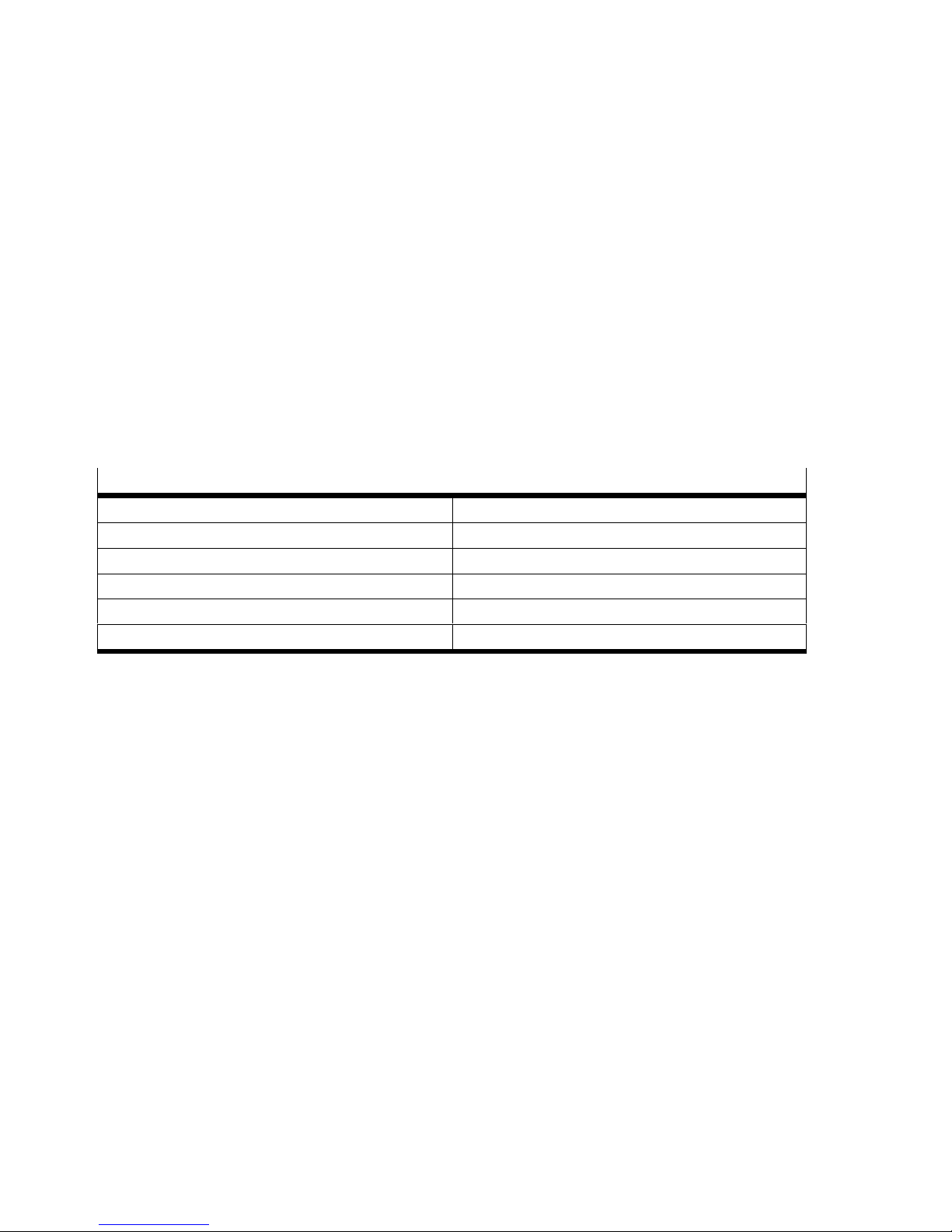
Electrical and environmental ratings
Input voltage Max. 30 V DC, Class 2
Input current 160 mA / max. 4.8 W
Analog output 4–20 mA
Transistor output max. 30 V DC, 100 mA G.P.
Maximum Ambient Temperature 70 °C / 158 °F
Enclosure Type Rating Type 1
12 Festo – SDAT-MHS – 2017-11f English
Page 13
SDAT-MHS
4 Installation
Installation and commissioning must be carried out only by properly qualified personnel in accordance
with these operating instructions.
4.1 Electrical
Warning
Risk of injury due to electric shock.
For the electric power supply, use only PELV circuits that ensure a reliable electric
disconnection from the mains network.
Observe IEC 60204-1/EN 60204-1.
Switched-mode power supplies are permitted, provided that they ensure reliable
separation in accordance with EN60950/VDE0805.
1. Make sure that the operating voltage is switched off.
2. Connect the M8 plug to the connecting cable of the higher-order controller.
– The tightening torque for the union nut of the plug: Max. 0.3 Nm.
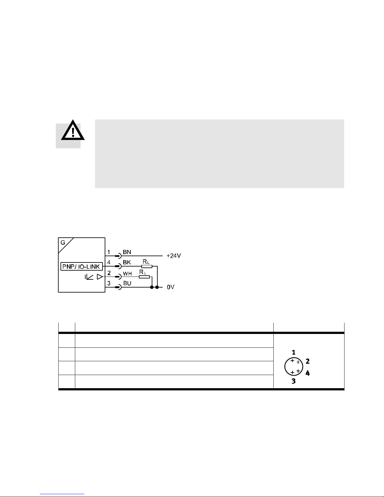
Fig. 7 Circuit diagram
Pin Allocation Plug
1 Operating voltage +24 V DC M8x1, 4-pin
2 Analogue output 0…20 mA
3 0 V
4 IO-Link/switching output (C/Q line)
Tab. 3 Pin allocation of plug connection
Festo – SDAT-MHS – 2017-11f English 13
Page 14
SDAT-MHS
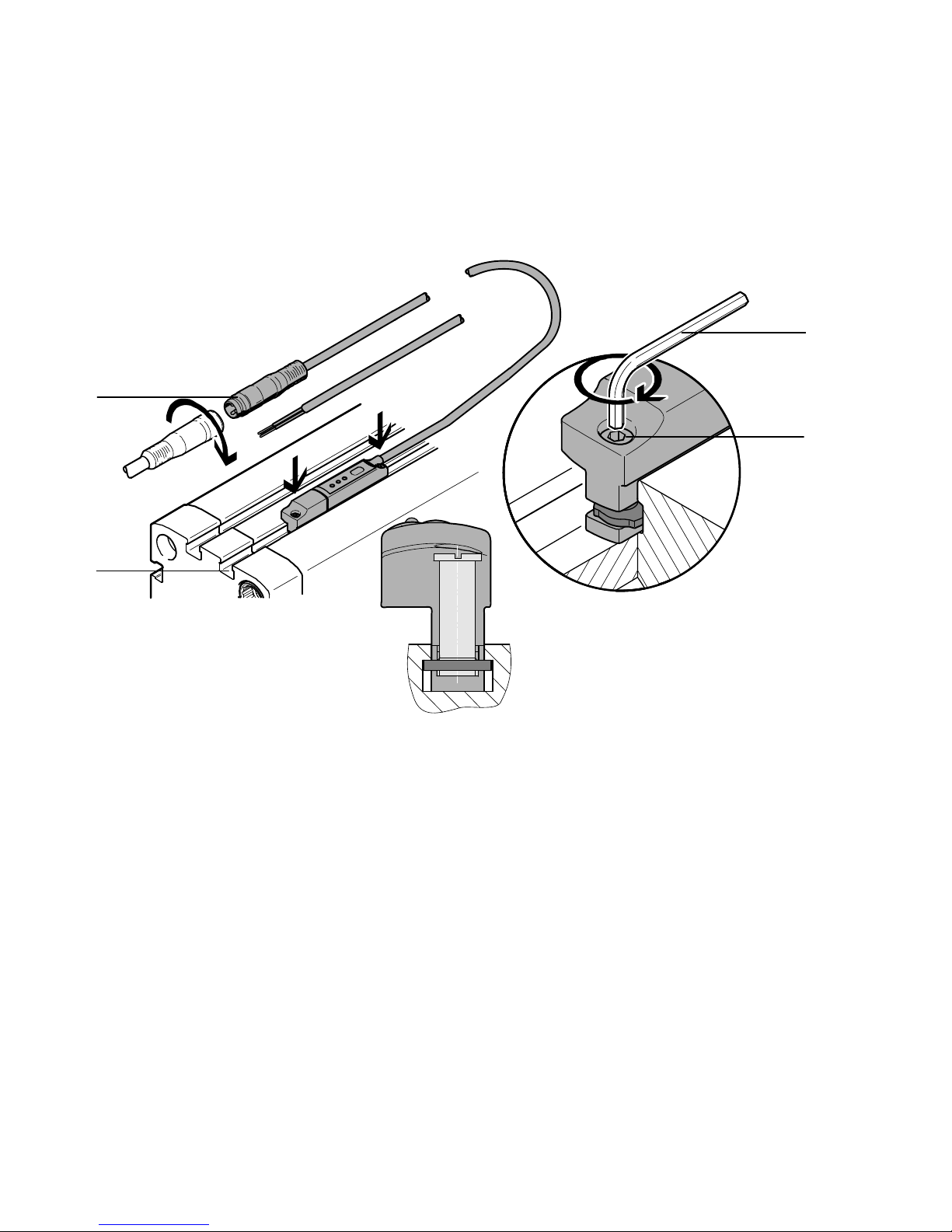
4.2 Mechanical
The mounting position is any desired.
4
0.3 Nm
3
1 Internal hexagon socket key
2 Mounting screw
Fig. 8 Mechanical installation
ß 1.5
0.5 Nm
3 T-slot (profile slot 8)
4 M8 plug
1
2
1. Insert the SDAT-MHS into the T-slot of the drive.
2. Move the piston into an end position of the application.
3. Push the SDAT-MHS in the direction of the piston until the red LED goes out.
4. Tighten the mounting screws hand-tight.
– max. tightening torque 0.5 Nm.
– tool: Internal hexagon socket key (size 1.5 mm).
14 Festo – SDAT-MHS – 2017-11f English
Page 15
SDAT-MHS
5 Commissioning
Installation and commissioning may only be performed in accordance with these instructions by techni
cians with appropriate qualifications.
1. Switch on the operating voltage.
è The LEDs illuminate (dependent on the piston position è Tab. 4).
è The device is ready for operation.
5.1 Set set-up mode
1. Press the operating key 3 times within 3 s.
è Set-up mode: Green and yellow LED flash simultaneously.
Note
After entry into the set-up mode, if programming is not completed within 60 s, the
SDAT-MHS automatically switches into the operating mode
5.2 Scale analogue signal
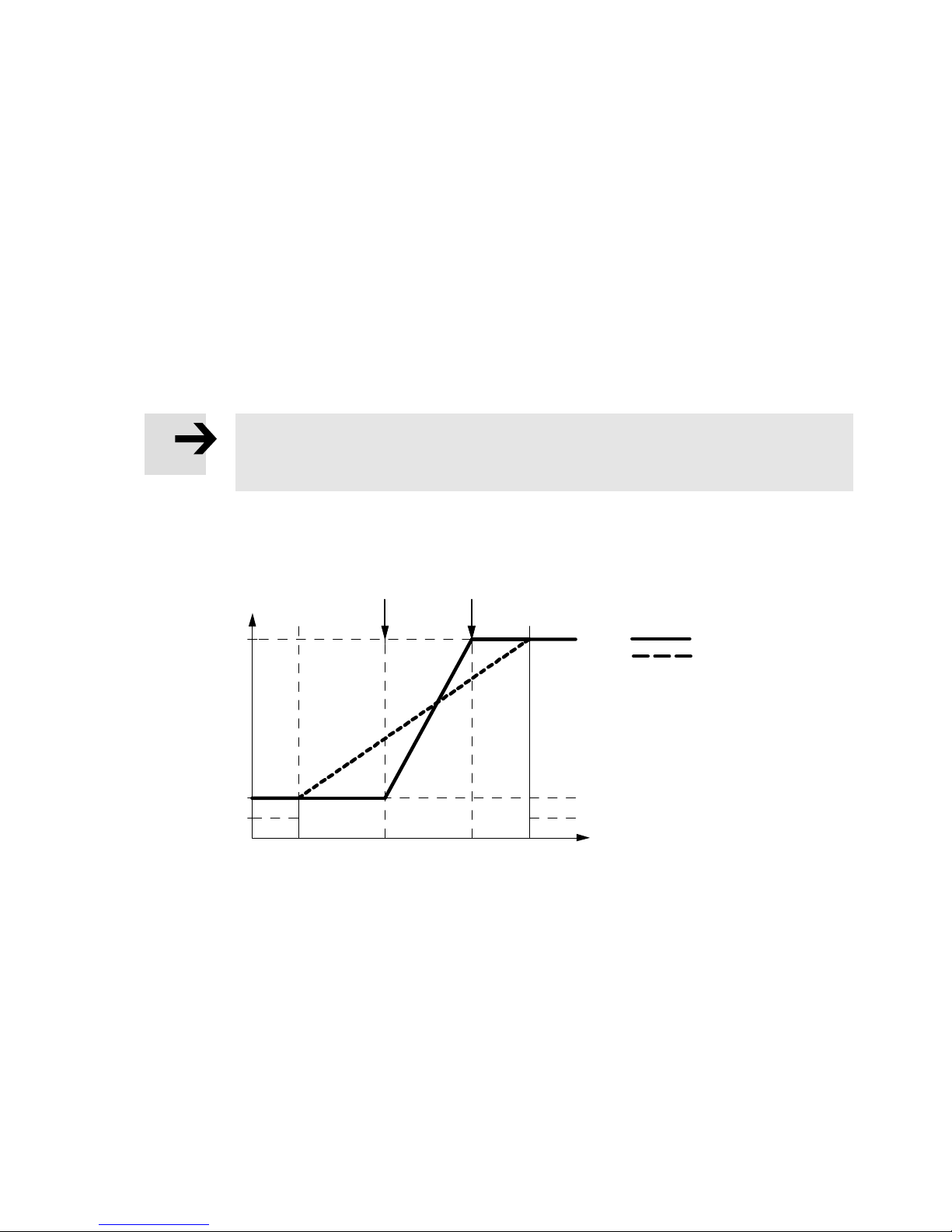
12
20 mA
4 mA
2 mA
0 mm 60 mm 120 mm 160 mm
1 Teach point 1
2 Teach point 2
Fig. 9 Scaling of the analogue signal (example SDAT-MHS-M160)
Requirement: The piston is in the sensing range (red LED off).
1. Change into the set-up mode (è Chapter 5.1).
2. Press the operating key 5 times in succession.
è Scale analogue output: The green LED flashes (5 times briefly in succession within 2 s).
3. Move the piston to the starting point of the desired sensing range.
4. Press the operating key.
è Teach point 1 (starting point of the sensing range) is established (4 mA).
è Green LED continues to flash, yellow LED flashing at 1 Hz.
5. Move the piston to the end point of the desired sensing range.
Analogue signal
Scaled
Not scaled
Festo – SDAT-MHS – 2017-11f English 15
Page 16
SDAT-MHS
6. Press the operating key.
è Teach point 2 (end point of the sensing range) is established (20 mA).
è Change into the operating mode.
Note
To invert the direction of increase of the analogue signal: Set teach point 2 (20 mA) on
the cylinder axis before teach point 1 (4 mA).
5.3 Program switching output
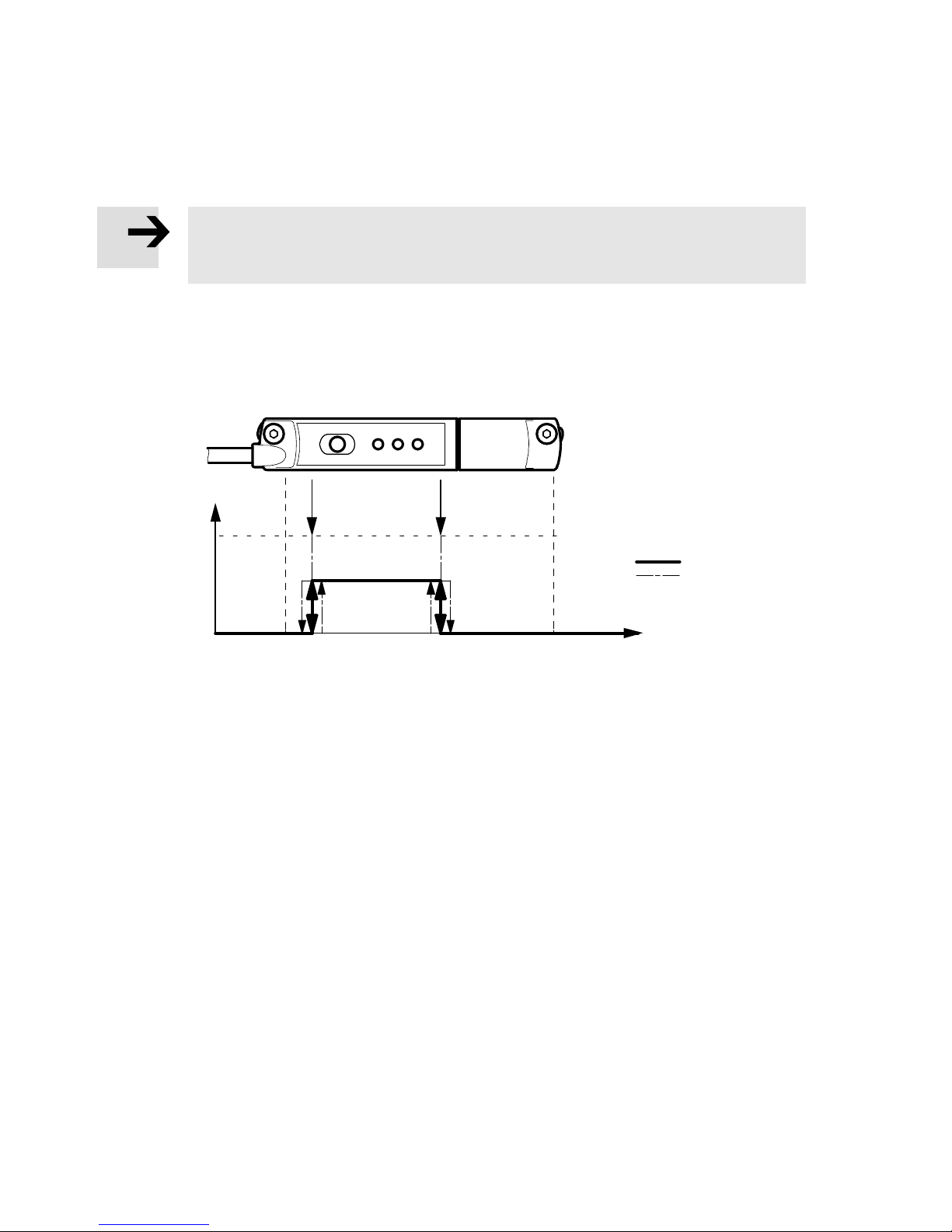
5.3.1 Set window comparator
12
OUT
1 Teach point 1
2 Teach point 2
Fig. 10 Window comparator
Requirement: The piston is in the sensing range (red LED off).
1. Change into the set-up mode (è Chapter 5.1).
2. Press the operating key 1 time.
è Green LED flashes (1 time within 2 s).
3. Move the piston to the 1st switching point (teach point 1).
4. Press the operating key 1 time.
è Switching point 1 is established.
è Green LED continues to flash, yellow LED flashing at 1 Hz.
5. Move the piston to the 2nd switching point (teach point 2).
6. Press the operating key 1 time.
è Switching point 2 is established.
è Change into the operating mode.
Switching travel
hysteresis
IN
16 Festo – SDAT-MHS – 2017-11f English
Page 17
SDAT-MHS
5.3.2 Set cylinder switch function
1
OUT
1 Teach point
Fig. 11 Cylinder switch function
Requirement: The piston is in the sensing range (red LED off).
1. Change into the set-up mode (è Chapter 5.1).
2. Press the operating key 2 times.
è Green LED flashes (2 times briefly in succession within 2 s).
3. Move the piston to the switching point (teach point 1).
4. Press the operating key 1 time.
è The switching point is established.
è Change into the operating mode.
Switching travel
hysteresis
IN
Festo – SDAT-MHS – 2017-11f English 17
Page 18
SDAT-MHS
5.3.3 Set hysteresis comparator
2
OUT
1 Teach point 1
2 Teach point 2
Fig. 12 Hysteresis comparator
Requirement: The piston is in the sensing range (red LED off).
1. Change into the set-up mode (è Chapter 5.1).
2. Press the operating key 3 times.
è Green LED flashes (3 times briefly in succession within 2 s).
3. Move the piston to the switch-on point (teach point 1).
4. Press the operating key 1 time.
è The switch-on point is established.
è Green LED continues to flash, yellow LED flashing at 1 Hz.
5. Move the piston to the reset point (teach point 2).
6. Press the operating key 1 time.
è The reset point is established.
è Change into the operating mode.
1
Switching travel
IN
5.3.4 Invert switching logic (NO or NC)
1. Change into the set-up mode (è Chapter 5.1).
2. Press the operating key 4 times.
è Green LED flashes (4 times briefly in succession within 2 s).
è Yellow LED illuminated: Currently set switching logic is NC.
è Yellow LED not illuminated: Currently set switching logic is NO.
3. Press the operating key.
è The switching logic is inverted.
è Change into the operating mode.
18 Festo – SDAT-MHS – 2017-11f English
Page 19

SDAT-MHS
5.4 Block / unblock operating key
In the IO-Link mode, the operating key is automatically and always blocked.
In the switching output operating mode, the operating key is unlocked as standard. But it can be
blocked in the IO-Link mode for the switching output operating mode:
1. Produce IO-Link mode.
2. Select key block for switching output operating mode in the IO-Link parameter menu:
– device access block,
– local user interface block.
LED display with blocked operating key:
– If the operating key is pressed: Green LED flashes 3 seconds at 3 Hz.
– Yellow LED displays the current status of the switching output.
– Red LED is illuminated only when the piston is outside the sensing range.
5.5 Program IO-Link output
The IO-Link function cannot be set via the operating keys on the device. All settings for set-up, commis
sioning and parameterisation are made in the higher-level controller of the IO-Link master.
1. Load the device description file IODD (è www.festo.com/sp) belonging to the device into the
interpreter of the IO-Link masters.
2. Connect the IO-Link/switching output to the IO-Link master.
3. Program the device. Observe the instructions on this in the operating instructions of the IO-Link
masters.
Note
If the device detects an error during commissioning, it is displayed on the user interface
of the IO-Link master and the programming option is closed.
Festo – SDAT-MHS – 2017-11f English 19
Page 20
SDAT-MHS
6 Operation
6.1 Magnetic direction detection and correction
At initial start-up or after a reset to factory settings, the position sensor emits signals directly using the
currently detected magnetic direction.
The magnetic direction detection and, with it, the signal curve are corrected during ongoing operation
when the following cases occur:
– The position sensor was placed in operation in a position where a correct magnetic direction detec
tion was not possible (e.g. due to ferromagnetic materials near the sensor or within the drive or
gripper).
– The position sensor was turned 180° in the slot after the magnetic direction was recognised as
stable.
Note
Brief incorrect signals at the sensor output can occur if automatic correction of the
magnetic direction detection is required è Chapter 8.2.
6.2 LED indicators
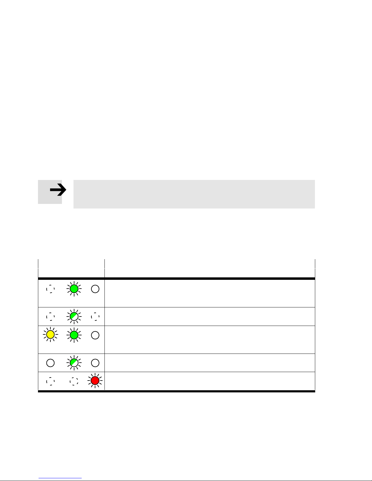
Status signals in normal operation
LED indicator Description
Yellow Green Red
Green LED illuminated: Ready status (yellow: Any, red: Off ).
– Analogue output function or switching output operating mode.
– Piston within the sensing range.
Green LED flashing at 1 Hz: Ready status.
– IO-Link operating mode.
Yellow and green LEDs illuminated: Ready status.
– Switching output switched.
– Piston in the range of a programmed function.
Green LED flashing 3 seconds at 3 Hz while the operating key is pressed:
Operating key blocked.
Red LED illuminated: Status display.
– Piston outside the sensing range.
Tab. 4 LED displays in normal operation
20 Festo – SDAT-MHS – 2017-11f English
Page 21
SDAT-MHS
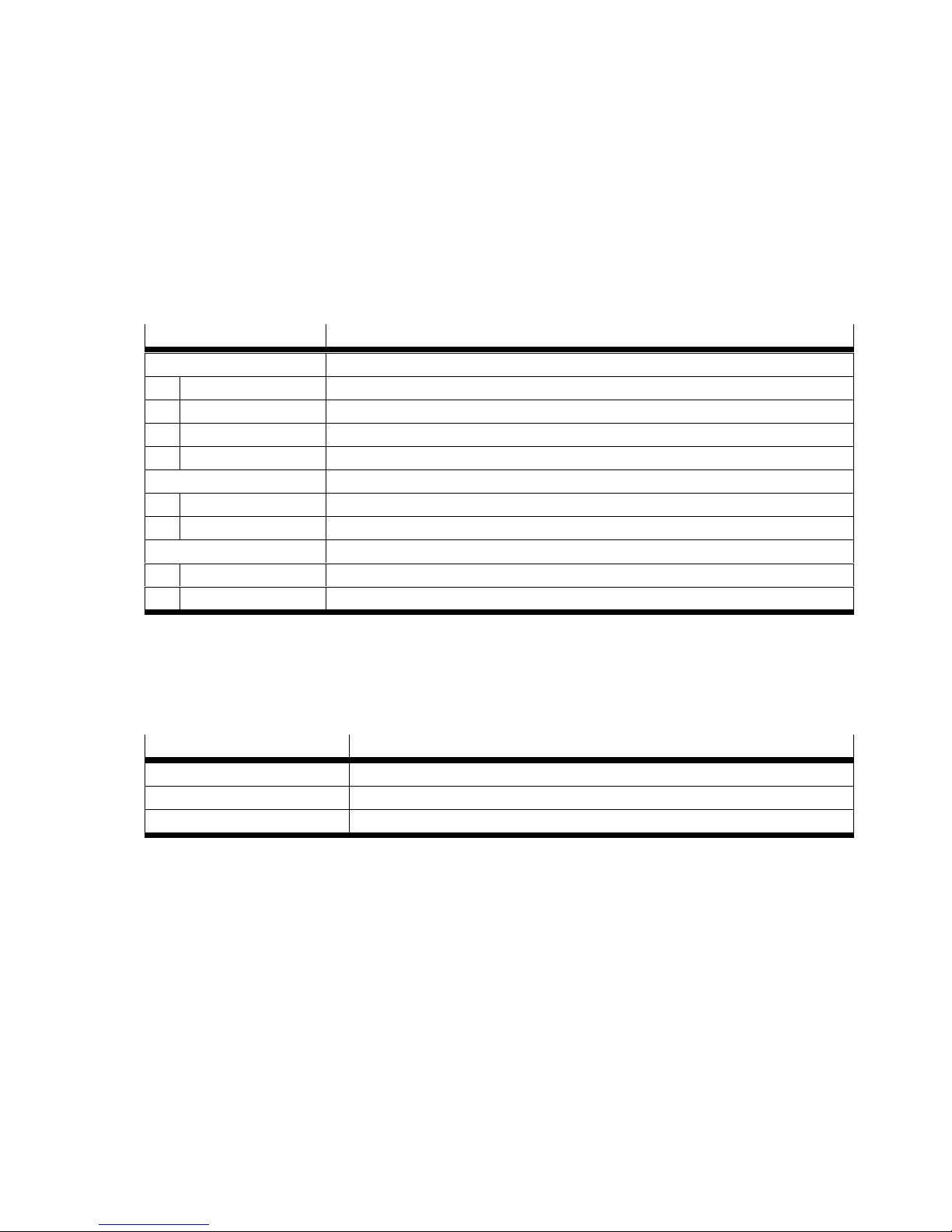
Interrogate configuration
The currently set configuration can be interrogated in the set-up mode.
1. Change into the set-up mode (è Chapter 5.1).
2. Press the operating key 6 times.
è Yellow, green and red LED flash cyclically according to the current configuration (è Tab. 5).
Another keystroke ends the interrogation and the SDAT-MHS changes into the operating mode. Without
a keystroke, the SDAT-MHS automatically changes into the operating mode after 60 s.
LED display Description
Green Function
No display Disabled
1 x flashing Window comparator
2 x flashing Cylinder switch function
3 x flashing Hysterisis comparator
Yellow Switching logic
1 x flashing Normally closed (NC)
2 x flashing Normally open (NO)
Red Scaling
1 x flashing User-configured
2 x flashing Total sensing range
Tab. 5 Status displays in the set-up mode
6.3 Reset position transmitter to factory setting
Parameter Factory setting
Switching function None
Switching logic Normally open (NO)
Scaling Total sensing range
Tab. 6 Factory settings SDAT-MHS
Calll factory setting
1. Change into the set-up mode (è Chapter 5.1).
2. Press the operating key 10 times.
è Yellow, green and red LED flash at 1 Hz.
3. Press the operating key.
è The position transmitter is reset to factory settings.
è Change into the operating mode.
Festo – SDAT-MHS – 2017-11f English 21
Page 22
SDAT-MHS
7 Disassembly
1. Switch off the operating voltage.
2. Separate the connections from the SDAT-MHS.
3. Loosen the mounting screws (è Fig. 8).
4. Take the SDAT-MHS out of the T-slot of the drive.
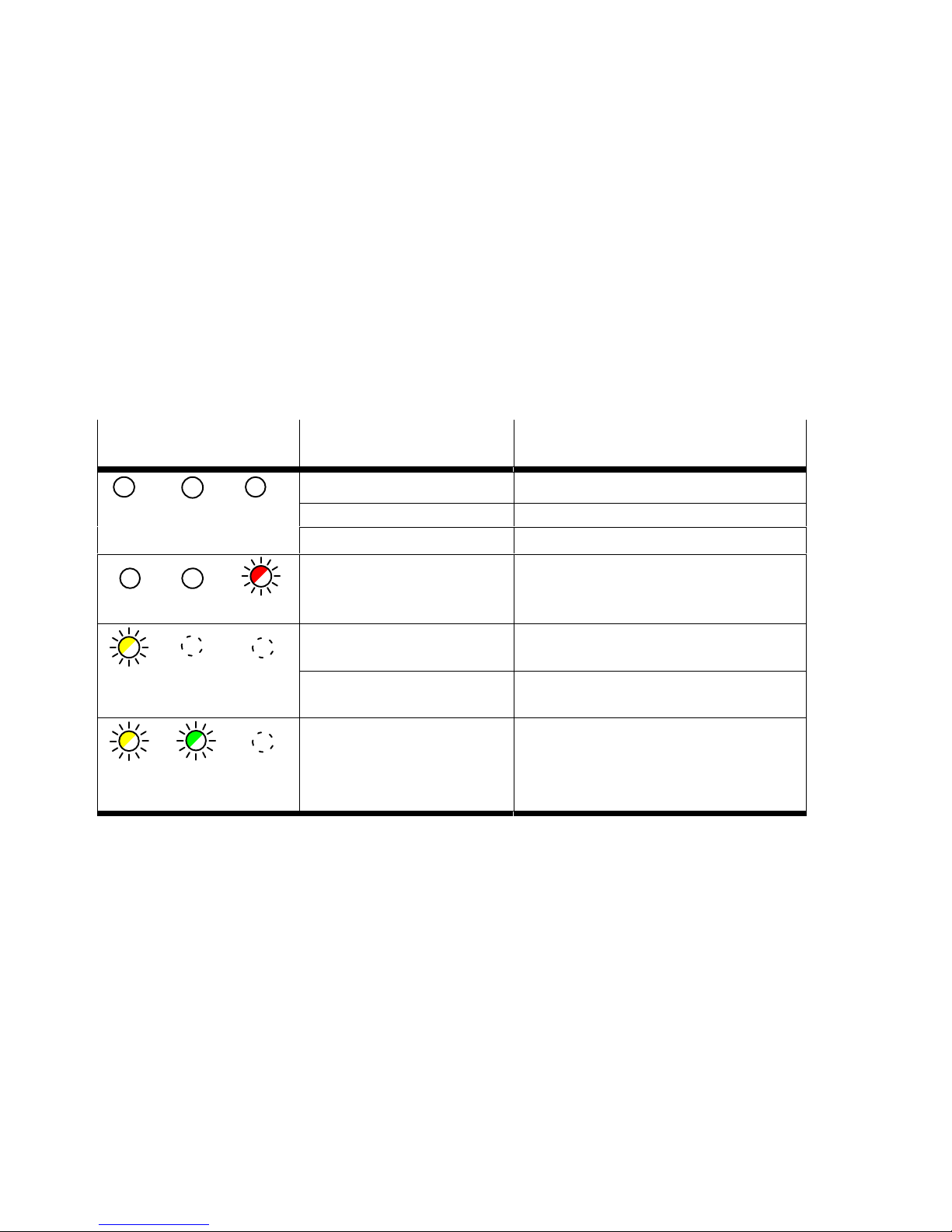
8 Fault clearance
8.1 Diagnostics via LED
LED display
Yellow Green Red
All LEDs off Connecting cable defective Replace the connecting cable.
Red LED flashing
Yellow LED flashing at 3 Hz Parameter error Reset device to factory setting
Yellow LED flashing at 3 Hz
Green LED flashing at 1 Hz
Tab. 7 LED indicators with malfunctions
Possible cause Remedy
Voltage supply defective Secure the power supply.
Sensor defective Replace device.
Sensor defective Switch power supply on/off.
Replace device.
Short circuit/overload at the
switching output
Communication error in the
IO-Link mode
Eliminate short circuit/overload.
(è Chapter 6.3).
Check IO-Link master.
Restart communication.
Check C/Q line.
22 Festo – SDAT-MHS – 2017-11f English
Page 23

SDAT-MHS
8.2 General malfunctions
Note
If the device detects an error during the IO-Link operation a status signal is emitted on
the IO-Link master. The IO-Link/switching output is not blocked.
Malfunction Possible cause Remedy
Incorrect or unexpected
signals at the analogue
output or in the IO-Link
process data
Switching output does not
switch corresponding to
the settings
Settings cannot be edited Access protection active Release key (only possible via
Inappropriate drive Use an appropriate drive.
Device defective Replace device.
No operating voltage or
impermissible operating voltage
Short circuit or overload at the
output
Magnetic objects in close
proximity to the position
transmitter
Sensor/drive rotated by 180°
after initial start-up
Incorrect or unexpected signals
during initial start-up on grippers
or in top elements which are
partly ferromagnetic
Short circuit or overload at the
output
Device defective Replace device.
Comply with operating voltage
range.
Eliminate short circuit/overload.
Prevent magnetic objects being in
close proximity.
Reset to factory settings (using
the operating key or via IO-Link).
At initial start-up, move gripper
jaws or pistons within the sensing
range (e.g. at both end positions).
Remedy short circuit / overload.
IO-Link).
Tab. 8 Possible malfunctions
9 Accessories
Accessories è www.festo.com/catalogue
Festo – SDAT-MHS – 2017-11f English 23
Page 24

SDAT-MHS
10 Technical data
10.1 General
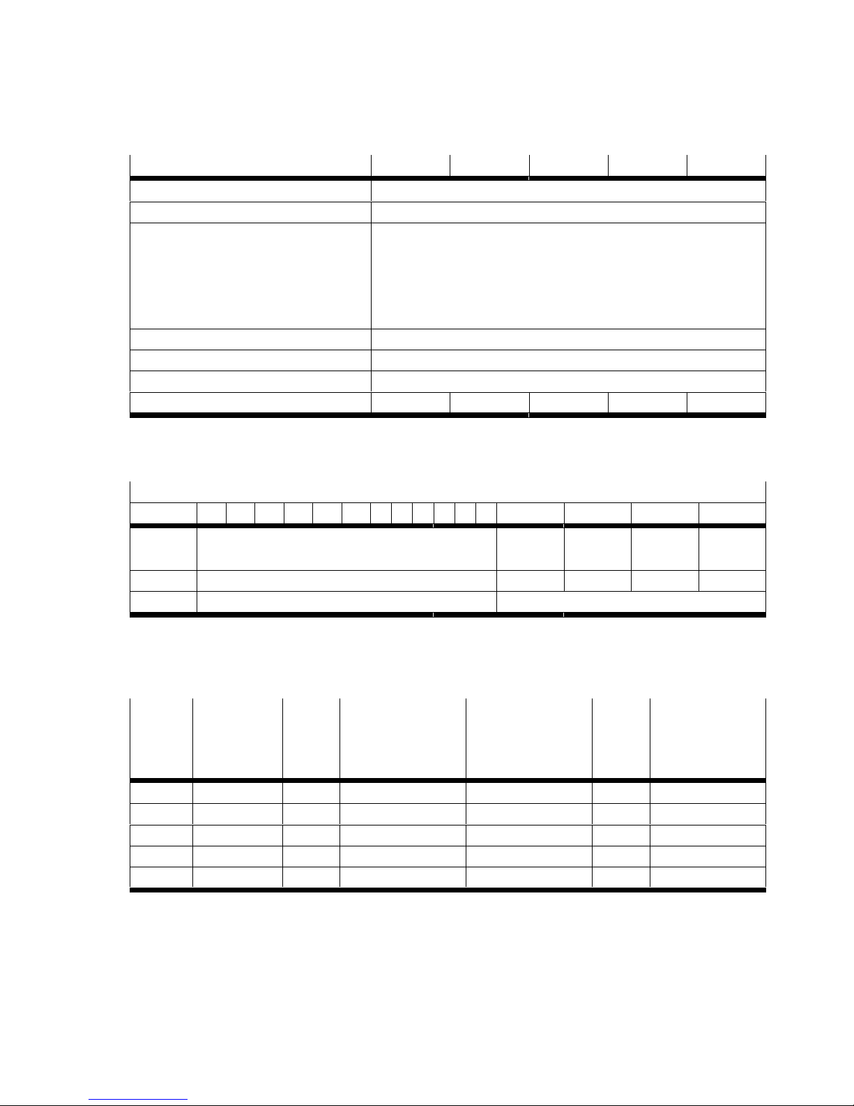
SDAT-MHS-... 50 80 100 125 160
Approval certificate RCM, c UL us - Listed (OL)
CE marking (è Declaration of conformity) In accordance with EU EMC Directive
Note on materials RoHS-compliant
Input signal/measuring element
Sensing range
Signal processing
Typical sampling interval [ms] 1
Max. speed of travel [m/s] 3
Output, general
Displacement resolution [mm] 0.05
Switching output
Switching output PNP
Repetition accuracy of switching point [mm] 0.1
Hysteresis [mm] ≤ 0.3
Analogue output
Analogue output [mA] 4…20
Sensitivity [mA/mm] 0.32 0.20 0.16 0.128 0.10
Typical linearity error [mm] ± 0.25
Repetition accuracy [mm] 0.1
Max. load resistance of current output [Ω] 500
Electronics
Operating voltage DC [V] 15…30
Typical signal running time [ms] < 2
Electromechanical
Cable length [m] 0.3
Conductor nominal cross section [mm2] 0.1
Mechanical system
Max. tightening torque [Nm] 0.5
Housing material information PA reinforced, polyester, high-alloy
Immission/emission
Ambient temperature [°C] –25…+70
Ambient temperature flexible cable installation [°C] –20…+70
Degree of protection (as per EN 60529) IP65/IP68
1)
[mm] 50 80 100 125 160
stainless steel, nickel-plated brass
(condition IP68: Test duration 24 h)
1) Type-dependent
Tab. 9 Technical data SDAT-MHS
24 Festo – SDAT-MHS – 2017-11f English
Page 25
SDAT-MHS
10.2 IO-Link
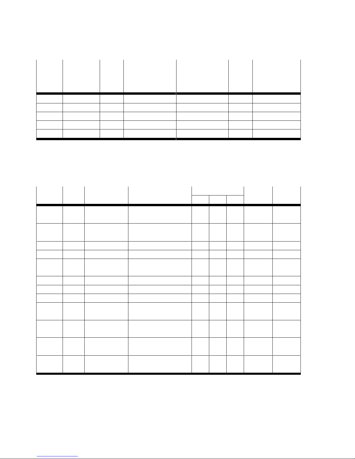
SDAT-MHS-... 50 80 100 125 160
Protocol version Device V1.1
Profile Smart Sensor Profile
Function classes 0x8000: Identification
0x8001:Binary Data Channel
0x8002:Process Data Variable
0x8003:Diagnosis
0x8004:Teach Channel
Communication mode COM3 (230,4 kBaud)
Process data length IN 2 Byte
Port class A, 4-pin
Device-ID 0x000001 0x000002 0x000003 0x000004 0x000005
Tab. 10 Physical layer
Process data record: 2 bytes
Bit 15 14 13 12 11 10 9 8 7 6 5 4 3 2 1 0
Process
Process Data Variable (PDV) èTa b . 12 BDC4
1)
BDC3
1)
BDC2
1)
BDC1
data
Data Position switch 4 switch 3 switch 2 switch 1
Type Unsigned Integer Boolean
1) BDC = Binary Data Channel
Tab. 11 Process data content
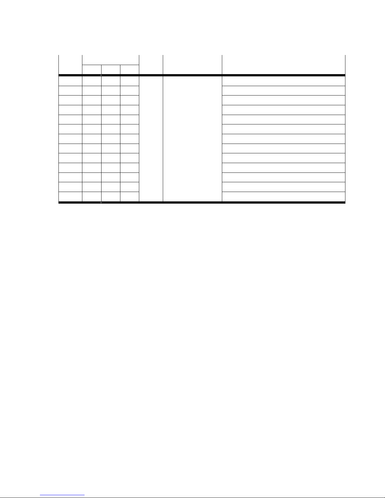
Raw data
Device
length
Sensing
range [mm]
PDV
Min.
OoR
PDV
Minimum value of
1)
nominal sensing
range
PDV
Maximum value
of nominal
sensing range
PDV
max.
OoR
PDV
OoR after Power
2)
ON
3)
-M50 0…50 0 21 1044 1064 4095
-M80 0…80 0 21 1659 1679 4095
-M100 0…100 0 21 2068 2088 4095
-M125 0…125 0 21 2580 2600 4095
-M160 0…160 0 21 3297 3317 4095
1)
1) Min OoR (OoR = Out of range): Minimum value of the sensing range
2) Max OoR (OoR = Out of range): Maximum value of the sensing range
3) OoR after Power ON: Outside of the sensing range when operating voltage is applied
Tab. 12 Range of values of the process data variables (PDV) for the device lengths
Festo – SDAT-MHS – 2017-11f English 25
Page 26
SDAT-MHS
Process data with use of IODD
Device
length
Sensing
range [mm]
PDV
Min.
OoR
PDV
Minimum value of
1)
nominal sensing
range
PDV
Maximum value
of nominal
sensing range
PDV
max.
OoR
PDV
OoR after Power
2)
ON
3)
-M50 0…50 0 103 5099 5196 19999
-M80 0…80 0 103 8102 8200 19999
-M100 0…100 0 103 10100 10198 19999
-M125 0…125 0 103 12600 12698 19999
-M160 0…160 0 103 16102 16200 19999
1) Min OoR (OoR = Out of range): Minimum value of the sensing range
2) Max OoR (OoR = Out of range): Maximum value of the sensing range
3) OoR after Power ON: Outside of the sensing range when operating voltage is applied
Tab. 13 Range of values of the process data variables (PDV) with use of IODD for the device lengths
Index Sub-
Name Default value
index
0x0002 0 System
Command
0x000C 0 Device Access
2)
Locks
Access
(example M50)
U M S
è Tab. 1 5 – W W 1 byte Unsigned
0 = Unlocked
R R/W R/W 2 bytes Record
1 = Locked
1)
Length Format
Integer
0x0010 0 Vendor Name Festo AG & Co.KG R R R 64 bytes String
0x0011 0 Vendor Text http://www.festo.com R R R 64 bytes String
0x0012 0 Product Name SDAT-MHS-
R R R 64 bytes String
M50-1L-SA-E-0.3-M8
0x0013 0 Product ID
3)
1531265 R R R 64 bytes String
0x0014 0 Product Text Position transmitter R R R 64 bytes String
0x0015 0 Serial-Number 12345678901 R R R 16 bytes String
0x0016 0 Hardware
REVxy R R R 64 bytes String
Revision
0x0017 0 Firmware
REVxy R R R 64 bytes String
Revision
0x0018 0 Application
Specific Tag
0x0028 0 Process Data
*** R/W R/W R/W 32 bytes String
4)
è Tab. 1 1 R R R 2 bytes Record
Input
1) Authorisation group U = user, M = maintenence, S = specialist;
Access W = write, R = read, R/W = read and write, – = no access
2) Bit 0: Lock parameter write access; Bit1: Lock data storage; Bit3: Lock local user interface (operating key)
3) Festo part number
4) Value defined by user
Tab. 14 Service data
26 Festo – SDAT-MHS – 2017-11f English
Page 27
SDAT-MHS
Value Access
1)2)
Length Format Comment
U M S
128 – – W 1 byte Unsigned Integer Reset Device
130 – – W Restore Factory Settings
176 – – W Reset Warnings
160 – W W Teach SP1 BDC1
161 – W W Teach SP2 BDC1
162 – W W Teach SP1 BDC2
163 – W W Teach SP2 BDC2
164 – W W Teach SP1 BDC3
165 – W W Teach SP2 BDC3
166 – W W Teach SP1 BDC4
167 – W W Teach SP2 BDC4
3)
3)
3)
3)
3)
3)
3)
3)
168 – W W Teach scale start analogue output
169 – W W Teach scale end analogue output
1) Authorisation group U = user, M = maintenence, S = specialist; access W = write, – = no access
2) If access = write, an attempted read access causes the error code 0x8101 to be returned
3) Access also possible through the standard function class 0x8004 “Teach Channel” of the Smart Sensor Profile
Tab. 15 System commands
Festo – SDAT-MHS – 2017-11f English 27
Page 28
SDAT-MHS
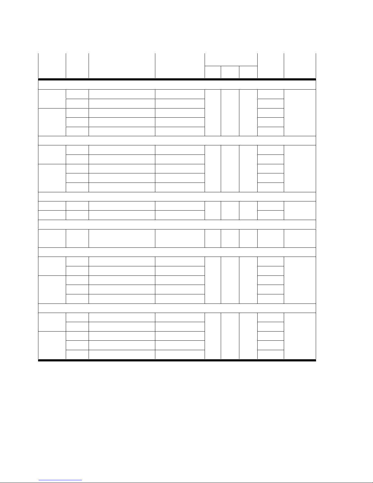
Index Sub-
index
Name Default value
(example
1)
M50)
Access
2)
U M S
Length Format
3)
BDC1
0x003C 1 Setpoint SP1 175 R R/W R/W 2 bytes Unsigned
2 Setpoint SP2 250 2 bytes
integer
0x003D 1 Switchpoint logic 0 1 byte
2 Switchpoint mode 0 1 byte
3 Switchpoint hysteresis 5 2 bytes
BDC2
0x003E 1 Setpoint SP1 275 R R/W R/W 2 bytes Unsigned
2 Setpoint SP2 350 2 bytes
integer
0x003F 1 Switchpoint logic 0 1 byte
2 Switchpoint mode 0 1 byte
3 Switchpoint hysteresis 5 2 bytes
Analogue current output
0x3000 1 Scale start 1 R R/W R/W 2 bytes Unsigned
2 Scale end 1063 2 bytes
integer
PDV 0: Normal, 1: Inverted, not for analogue current output
0x3010 0 PDV inversion 0 R R/W R/W 1 byte Unsigned
integer
BDC3
0x4000 1 Setpoint SP1 375 R R/W R/W 2 bytes Unsigned
2 Setpoint SP2 450 2 bytes
integer
0x4001 1 Switchpoint logic 0 1 byte
2 Switchpoint mode 0 1 byte
3 Switchpoint hysteresis 5 2 bytes
BDC4
0x4002 1 Setpoint SP1 475 R R/W R/W 2 bytes Unsigned
2 Setpoint SP2 550 2 bytes
integer
0x4003 1 Switchpoint logic 0 1 byte
2 Switchpoint mode 0 1 byte
3 Switchpoint hysteresis 5 2 bytes
1) Raw data without use of IODD
2) Authorisation group U = user, M = maintenence, S = specialist; access R = read, R/W = read and write
3) Code BDC1…BDC4 è Tab. 17
Tab. 16 Parameters
28 Festo – SDAT-MHS – 2017-11f English
Page 29
SDAT-MHS
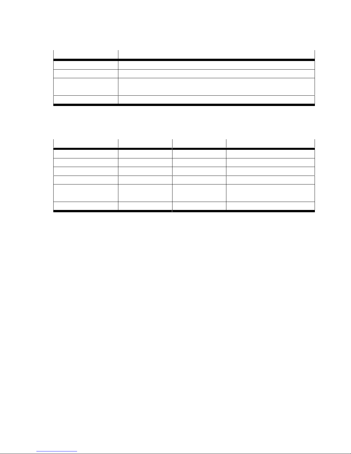
Name Code
Setpoint SP1/SP2
1
12 bit position values
Switchpoint logic 0 = output signal not inverted; 1 = output signal inverted
Switchpoint mode 0 = deactivated; 1 = cylinder switch,
2 = window comparator, 3 = hysteresis comparator
Switchpoint hysteresis Fix: 5
1) Range of values è LEERER MERKER
Tab. 17 Code switch point parameter
Error code Mode Type Comment
0x4000 (Dis)appear Error Temperature error
0x5000 (Dis)appear Error Hardware defective
0x5111 (Dis)appear Warning Voltage too low
0x6320 (Dis)appear Error Parameter error
0x8CA0 (Dis)appear Error Magnetic field too weak,
inappropriate drive
0xFF91 SingleShot Notification Data storage upload request
Tab. 18 Error codes
Festo – SDAT-MHS – 2017-11f English 29
Page 30
SDAT-MHS
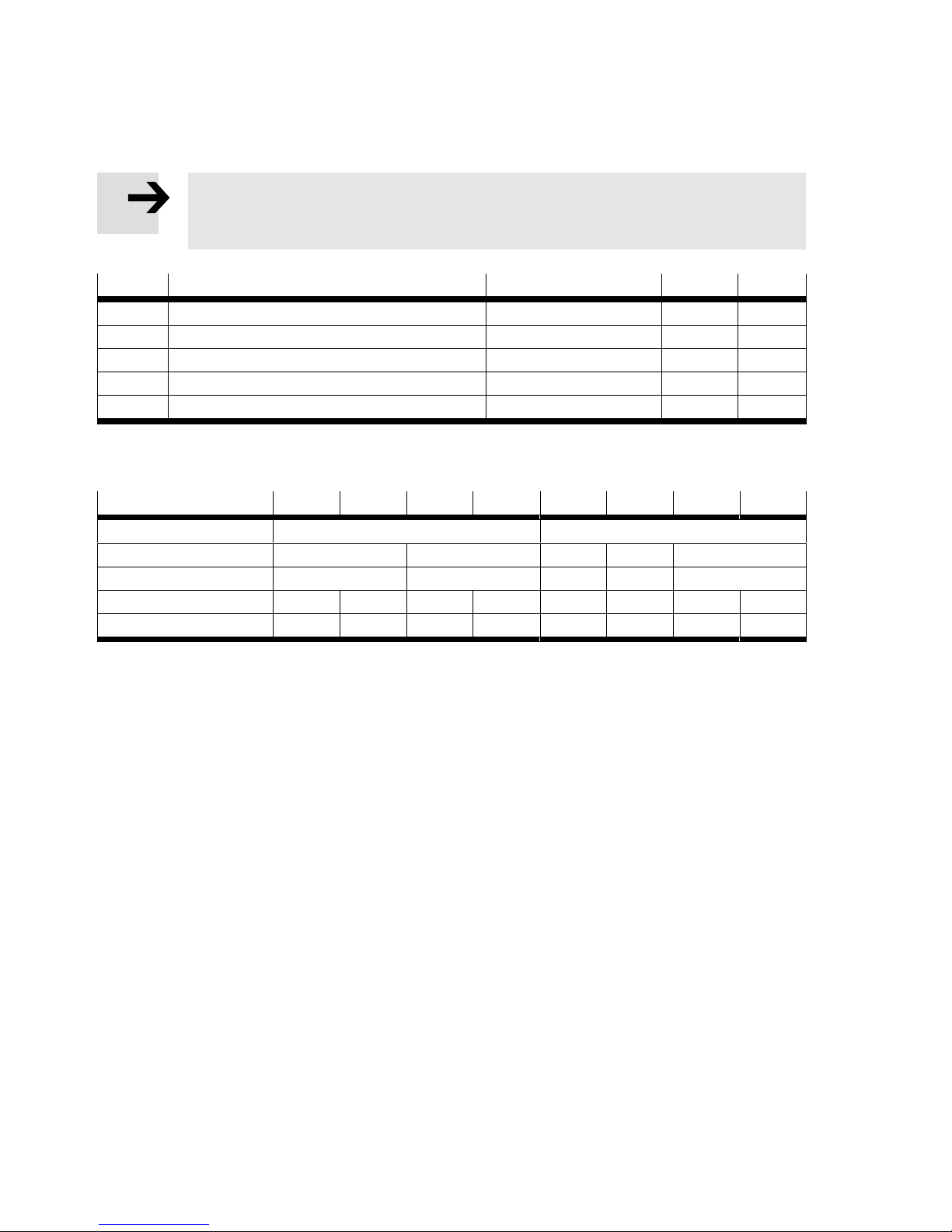
10.3 I-Port
Note
In principle, the data of the IO-Link specification apply (èchap.10.2).
For specifications on the process data contents èTab. 11.
Index Name Default value Access1)Length
0x0040 Device attributes 0x00 R/W 1 byte
0x0041 Extended parameters 0x0000 R/W 2 bytes
0x0042 Diagnosis parameter 0x0000 R 2 bytes
0x0043 Device specific parameters èTab. 20 R/W 8 bytes
0x00FE I-Port Revision 0x0101 R/W 2 bytes
1) Access R = read, R/W = read and write
Tab. 19 Additionally supported parameters in accordance with I-Port specification
Byte 1 2 3 4 5 6 7 8
IO-Link Index 0x003C 0x003D
Subindex 1 2 1 2 3
Function
1)
SP1 SP2 Logic Mode HY
Byte high low high low high low
Default value 0x00 0xAF 0x00 0xFA 0x00 0x00 0x00 0x05
1) Parameter coding èTab. 17
Tab. 20 Device Specific Parameters
30 Festo – SDAT-MHS – 2017-11f English
Page 31
SDAT-MHS
11 Appendix
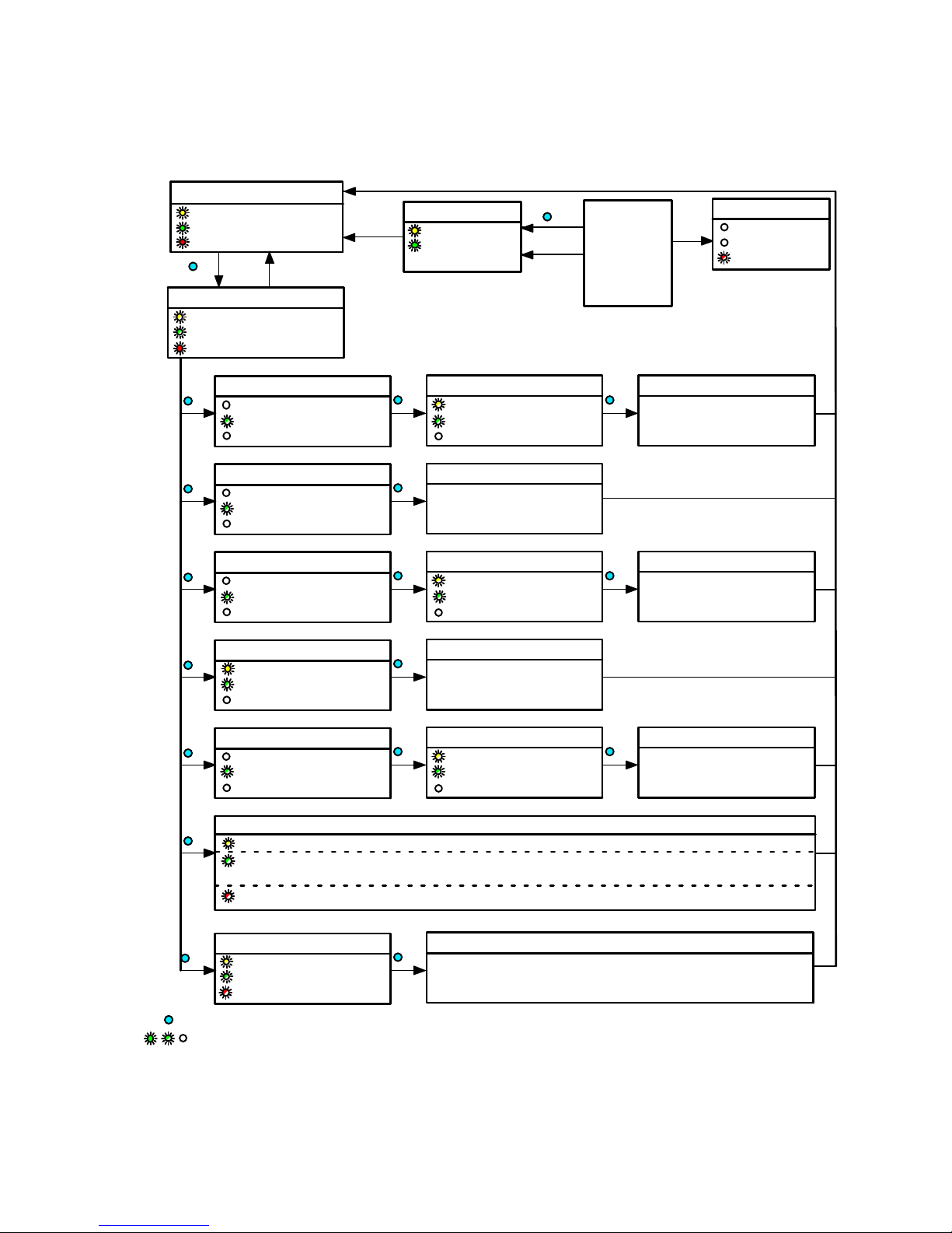
SIO operation
Switching output status
ON
ON, if OoR
3 x
Set-up mode
Yellow +
Green flash simultaneously
ON, if OoR
Window comparator
1 x
Cylinder switch function
2 x
Hysterisis comparator
3 x
Key combination
invalid
Yellow OFF
1 x flash briefly / 2 s
Red OFF, if in range
Yellow OFF
2 x flash briefly / 2 s
Red OFF, if in range
Yellow OFF
3 x flash briefly / 2 s
Red OFF, if in range
Abort
Yellow +
Green ON for
0.5 s
Teach point 1
1 x
Flashes
1)
1)
1)
1 x flash briefly / 2 s
Red OFF, if in range
Teach point
1 x
Teach point 1
1 x
Flashes
3 x flash briefly / 2 s
Red OFF, if in range
3 s
t > 60 s
1)
1)
From each
status in the
diagram
Teach point 2
1 x
Teach point 2
1 x
Errors
Yellow OFF
Green OFF
Red flash 3 Hz
Switching logic NO/NC
4 x
ON if NO / OFF if NC
4 x flash briefly / 2 s
Red OFF, if in range
Scale
5 x
Yellow OFF
5 x flash briefly / 2 s
Red OFF, if in range
Display configuration: Cyclical flash signals in the sequence green - yellow - red
6 x
Switching logic: 1 x - normally closed (NC), 2 x - normally open (NO)
Function: 0 x - deactivated, 1 x - window comparator, 2 x - cylinder switch function,
3 x - hysteresis comparator
Scaling: 1 x - user-configured, 2 x - total sensing range
Reset
10 x
1 x = Press operating key (e.g.: 1 x)
= LED illuminated / LED flashing / LED OFF (e.g.: Green LED)
1) Teaching of a position out-of-range (OoR) causes the red LED to flash until the magnet is back in the sensing range (in range).
Yellow + green + red flash
simultaneously at 1 Hz
1)
1)
Inverting NO or NC
1 x
Teach point 1 (4 mA)
1 x
Flashes
5 x flash briefly / 2 s
Red OFF, if in range
Factory setting
1 x
Switching function: None
Switching logic: Normally open (NO)
Scaling: Total sensing range
Teach point 2 (20 mA)
1 x
1)
Fig. 13 Settings via the operating key and LED indicators (not IO-Link operation)
Festo – SDAT-MHS – 2017-11f English 31
Page 32

Copyright:
Festo AG & Co. KG
Ruiter Straße 82
73734 Esslingen
Germany
Phone:
+49 711 347-0
Fax:
+49 711 347-2144
Reproduction, distribution or sale of this document or communica
tion of its contents to others without express authorization is
prohibited. Offenders will be liable for damages. All rights re
served in the event that a patent, utility model or design patent is
registered.
e-mail:
[email protected]
Internet:
www.festo.com
 Loading...