

Page 1
8091014
SDAS-MHS
Position transmitter
8091014
2018-06
[8091016]
Description|Function,
Operating
Page 2

Translation of the original instructions
2 Festo — SDAS-MHS — 2018-06
Page 3

3Festo — SDAS-MHS — 2018-06
1 About this document................................................................................................... 5
1.1 Further applicable documents...................................................................................... 5
2 Safety........................................................................................................................... 5
2.1 Intended use................................................................................................................ 5
2.2 General safety instructions........................................................................................... 5
2.3 Area of application and approval.................................................................................. 5
2.4 Training of qualified personnel..................................................................................... 5
3 Product overview......................................................................................................... 6
3.1 Design........................................................................................................................... 6
3.2 Characteristics.............................................................................................................. 7
4 Function........................................................................................................................7
4.1 Cylinder switch operating mode................................................................................... 8
4.1.1 Cylinder switch function..........................................................................................9
4.2 Position transmitter operating mode (IO-Link).............................................................. 10
4.2.1 Cylinder switch function..........................................................................................11
4.2.2 Window comparator................................................................................................12
4.2.3 Hysteresis comparator............................................................................................13
4.2.4 Switching logic, normally open (NO) and normally closed (NC)...............................14
4.3 Additional information on the operating modes........................................................... 14
5 Installation.................................................................................................................. 16
5.1 Electrical installation.................................................................................................... 16
5.2 Mechanical installation................................................................................................. 17
6 Commissioning............................................................................................................ 17
6.1 Cylinder switch operating mode................................................................................... 18
6.1.1 Activating set-up mode........................................................................................... 18
6.1.2 Set switching points................................................................................................19
6.1.3 Changing the configuration of the switching outputs..............................................19
6.1.4 Menu structure....................................................................................................... 20
6.2 Position transmitter operating mode............................................................................ 21
7 Operation..................................................................................................................... 21
7.1 Cylinder switch operating mode................................................................................... 21
7.1.1 LED display............................................................................................................. 22
7.1.2 Reset to factory setting........................................................................................... 22
7.2 Position transmitter operating mode............................................................................ 22
7.2.1 LED display............................................................................................................. 22
7.2.2 Reset to factory setting........................................................................................... 23
8 Fault clearance............................................................................................................ 23
8.1 Diagnostics via LED...................................................................................................... 23
8.2 General malfunctions................................................................................................... 24
9 Disassembly................................................................................................................ 24
Table of contents
Page 4

10 Technical data.............................................................................................................. 25
10.1 General..........................................................................................................................25
10.2 IO-Link...........................................................................................................................26
4 Festo — SDAS-MHS — 2018-06
Page 5

5Festo — SDAS-MHS — 2018-06
1 About this document
This document describes the use of the above-mentioned product.
1.1 Further applicable documents
All available documents for the product èwww.festo.com/pk.
2 Safety
2.1 Intended use
The position transmitter SDAS-MHS is intended for monitoring the piston stroke. Only use the position
transmitter for suitable drives from Festo èwww.festo.com/catalogue. Avoid positioning magnetic
objects in close proximity to the position transmitter.
2.2 General safety instructions
– Only use the product in original status without unauthorised modifications.
– textvar object does not exist
– Take into consideration the ambient conditions at the location of use.
– Observe limit values è 10 Technical data.
Return to Festo
– Consult your regional Festo contact.
2.3 Area of application and approval
NOTICE!
CE declaration of conformity èwww.festo.com/sp.
2.4 Training of qualified personnel
Installation, commissioning, maintenance and disassembly should only be conducted by qualified personnel.
About this document
Page 6
3 Product overview
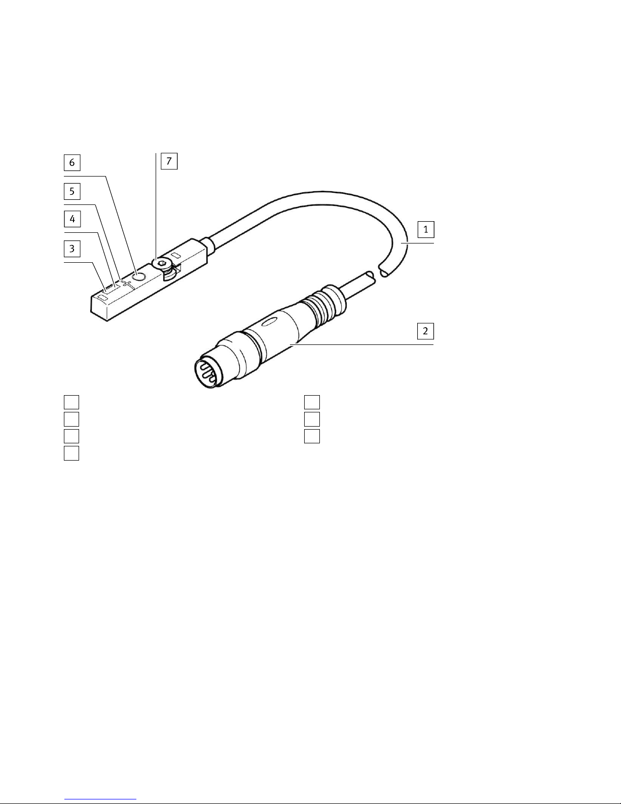
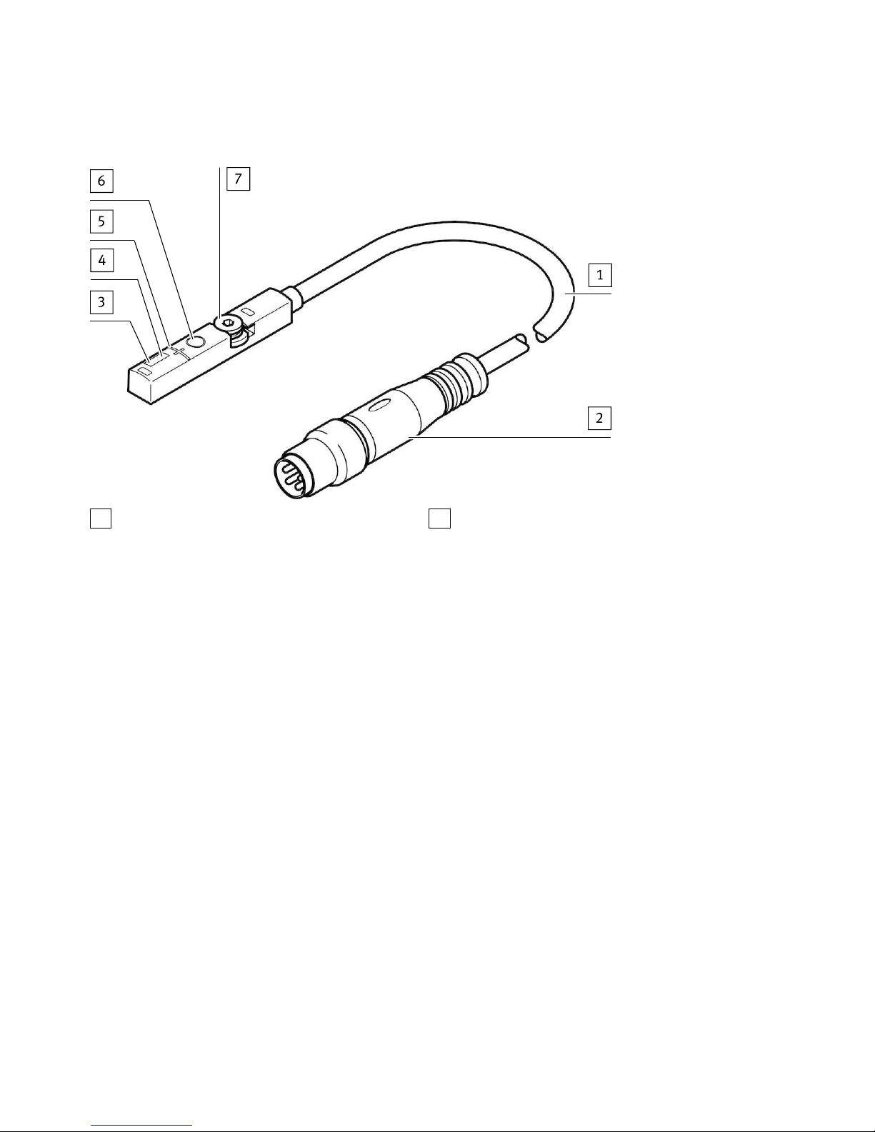
3.1 Design
1
Connecting cable
2
M8 plug, rotatable
3
Red LED: status display
4
Yellow LED: switching status display
5
Marking: centre of the sensing range
6
Capacitive operating key
7
Retaining screw
Fig. 1 Design of SDAS-MHS
Product overview
6 Festo — SDAS-MHS — 2018-06
Page 7
3.2 Characteristics
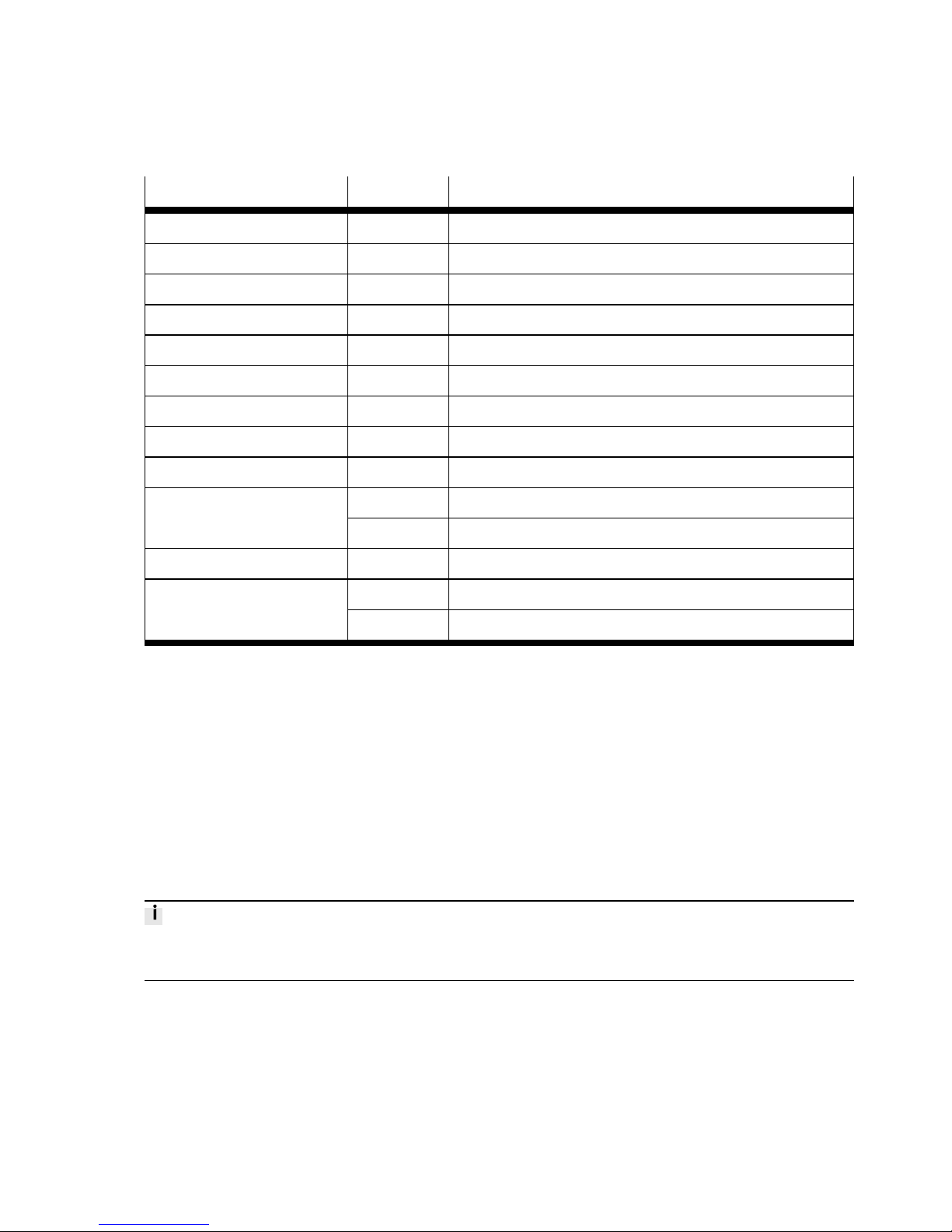
Characteristic Value Description
Position transmitter SDAS-
Sensor version M Insertable in slot
Sensor principle HS- Hall sensor
Measuring range M40- Typically up to 40mm
Nominal operating voltage 1 24VDC
Display L- LED
Electrical output 1 PNLK- PNP or NPN or IO-Link
Electrical output 2 PN- PNP or NPN
Cable characteristic E- Suitable for use with energy chains/robots
0.3- 0.3mCable length
2.5- 2.5m
Outgoing circuit
–
Axial
LE Open endElectrical connection
M8 M8 plug
Tab. 1 Overview of variants
4 Function
The position transmitter detects the magnetic field of the piston magnet and continuously senses the
piston movement in the sensing range. The position transmitter can be operated in one of the following operating modes:
– Cylinder switch with 2 programmable switching points (standard operation)
è 4.1 Cylinder switch operating mode.
– Position transmitter with IO-Link communication
è 4.2 Position transmitter operating mode (IO-Link).
In the case of active IO-Link communication (IO-Link master required), the SDAS-MHS switches automatically into the position transmitter operating mode.
Function
7Festo — SDAS-MHS — 2018-06
Page 8
4.1 Cylinder switch operating mode
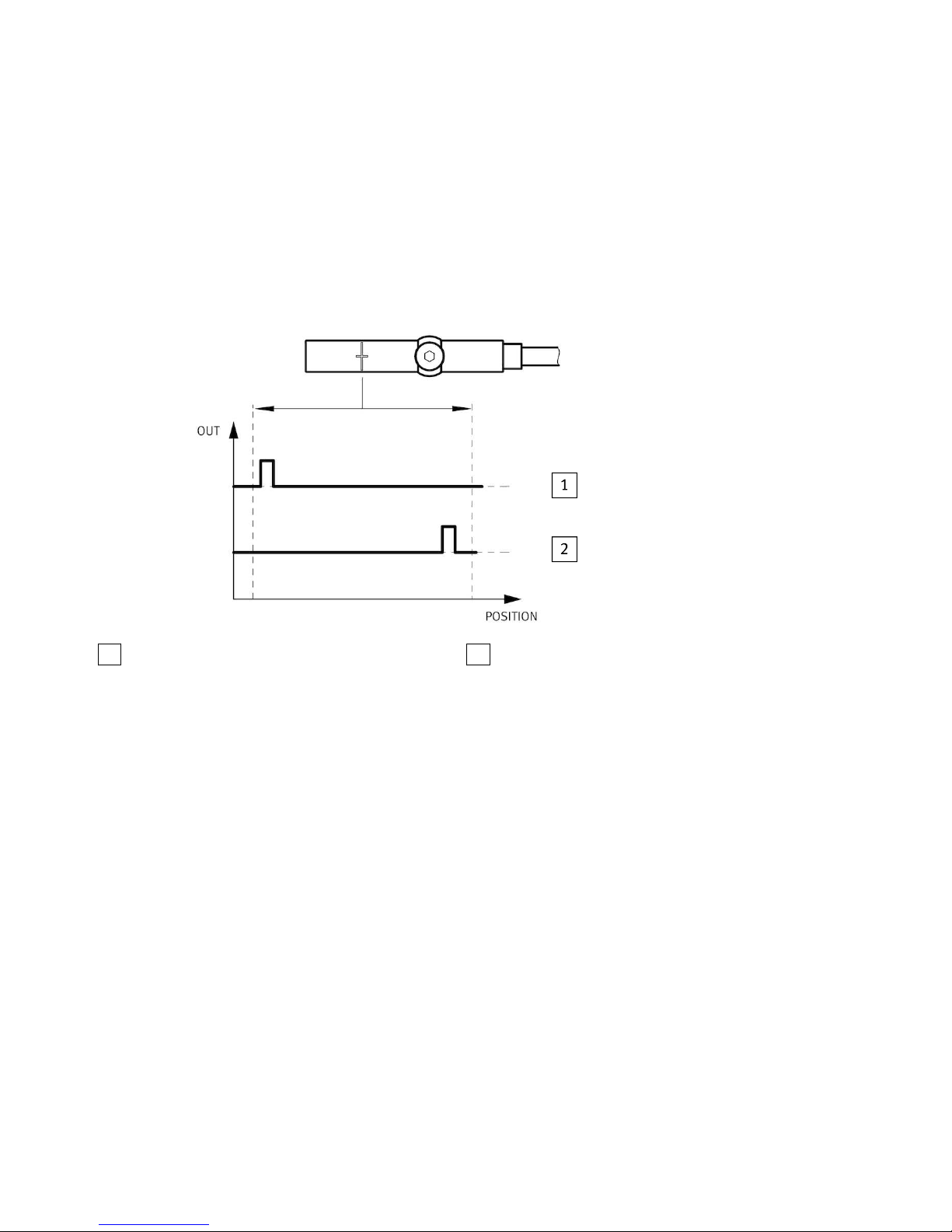
In the cylinder switch operating mode, 2 switching points can be programmed within the sensing
range.
– Operation using capacitive operating key
– Switching logic: normally open (NO)
– Output signal 24VDC (PNP or NPN)
– Marking on the housing indicates the centre of the sensing range.
1
Electrical output 1
2
Electrical output 2
Fig. 2 Application example: Cylinder switch operating mode
Function
8 Festo — SDAS-MHS — 2018-06
Page 9
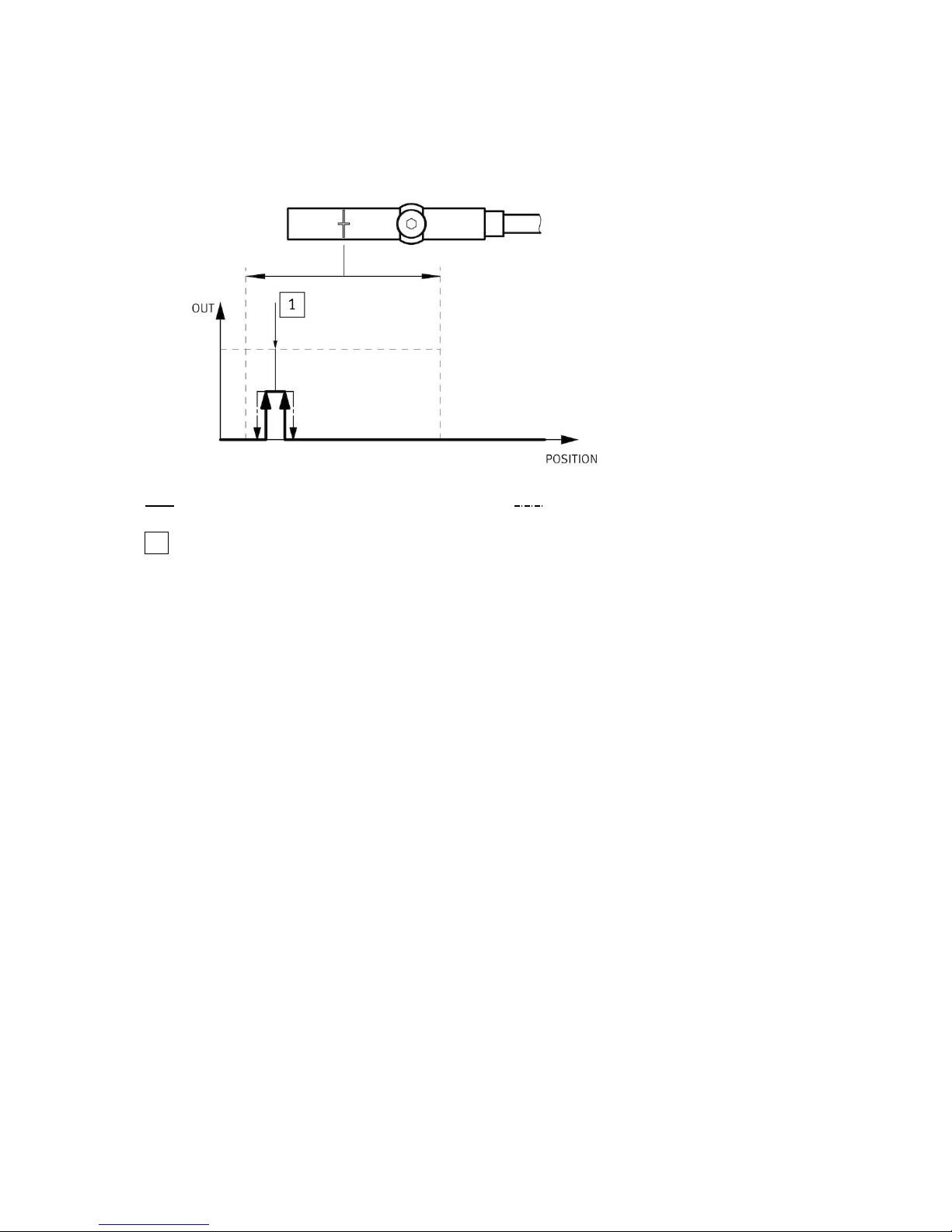
4.1.1 Cylinder switch function
Output signal Hysteresis
1
Teach-in point
Fig. 3 Cylinder switch function
– The teach-in point is located in the centre of the switching window.
– The switching window and hysteresis are preset and cannot be changed.
Function
9Festo — SDAS-MHS — 2018-06
Page 10
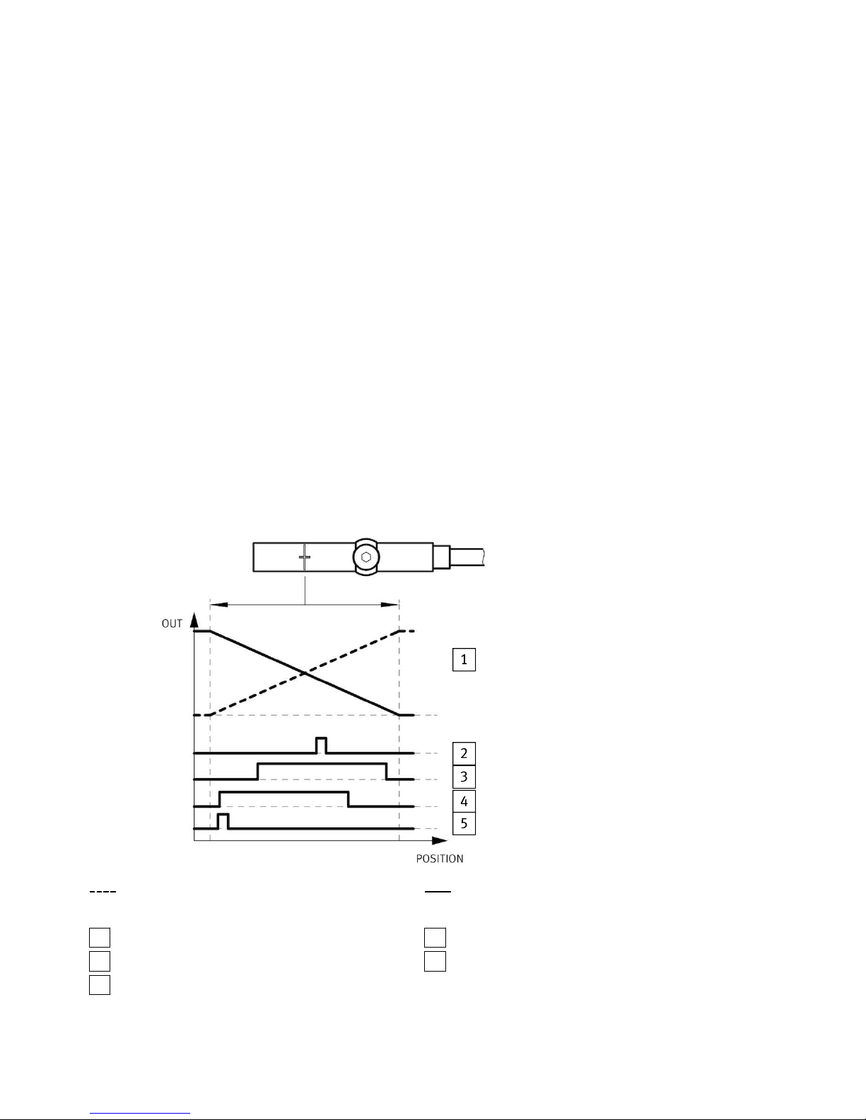
4.2 Position transmitter operating mode (IO-Link)
In the position transmitter operating mode, programmed switching signals and the continuous position values (digitally coded analogue values) are transferred.
– Programming via IO-Link
– Device description file IODD èwww.festo.com/sp.
– Capacitive operating key is deactivated.
– Cylinder switches or window comparators or hysteresis comparators can be programmed individu-
ally on 4 switching channels.
– The continuous position values are always transferred in parallel with and independently of the
position value output of the switching channels.
– Each channel can be set to be normally closed (NC) or normally open (NO).
– Data transmission is serially and digitally coded in the IO-Link protocol.
– Process data: 12 bit for position data and 4 bit for switching channels è 10 Technical data.
– Unshielded standard cables of up to 20m in length can be used.
– Parameters and functions in accordance with Smart Sensor profile
– Support for the optional functions “Block parameterisation” and “Data storage”
– The direction of increase of the process data values (PDV) can be inverted. As delivered: lowest
PDV at cable end
Output signal (PDV): direction of increase
inverted
Output signal (PDV): direction of increase
as delivered
1
PDV (position data values)
2
SSC1 (switching signal channel)
3
SSC2
4
SSC3
5
SSC4
Fig. 4 Application example: Position transmitter operating mode
Function
10 Festo — SDAS-MHS — 2018-06
Page 11
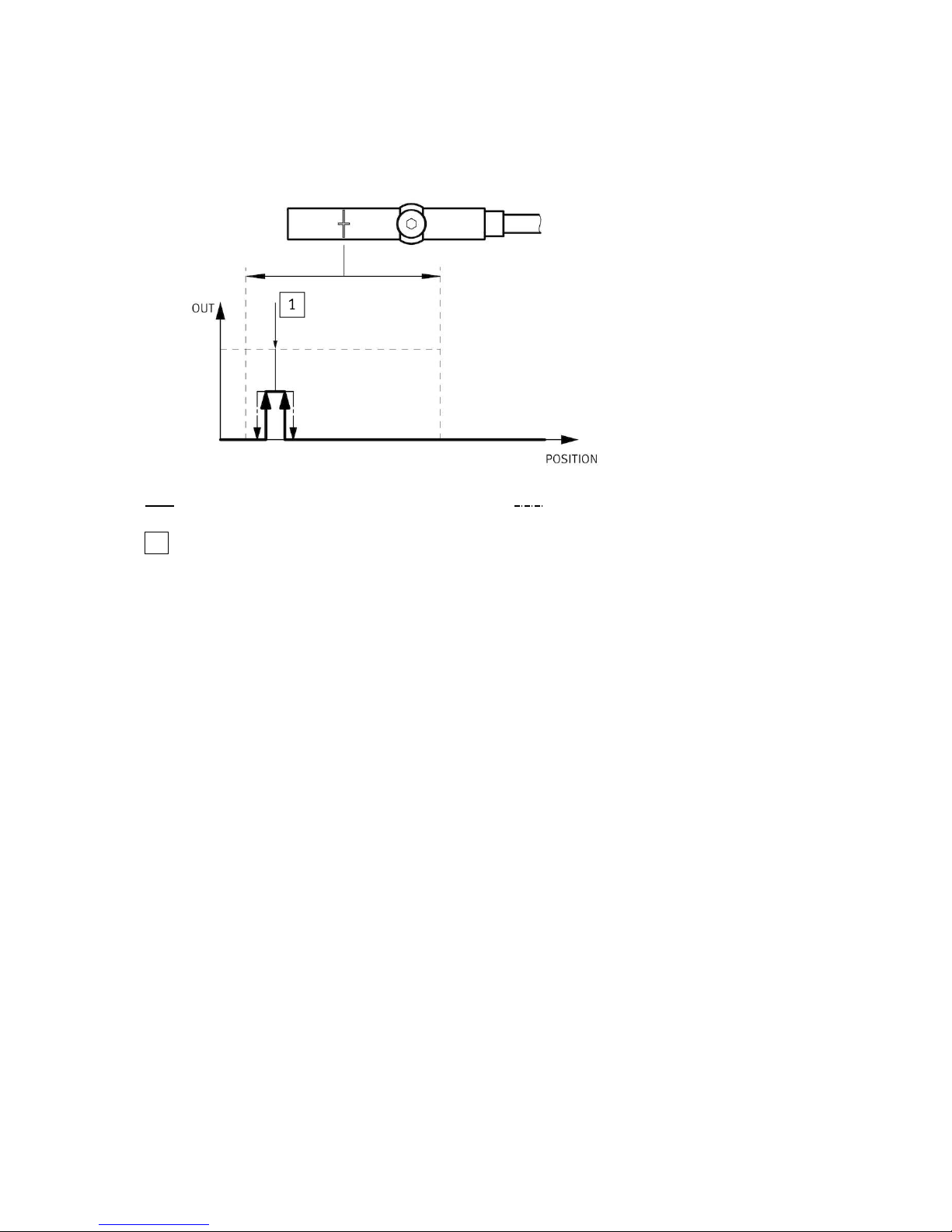
4.2.1 Cylinder switch function
Output signal Hysteresis
1
Teach-in point
Fig. 5 Cylinder switch function
– The teach-in point is located in the centre of the switching window.
– The switching window and hysteresis are preset and cannot be changed.
Function
11Festo — SDAS-MHS — 2018-06
Page 12
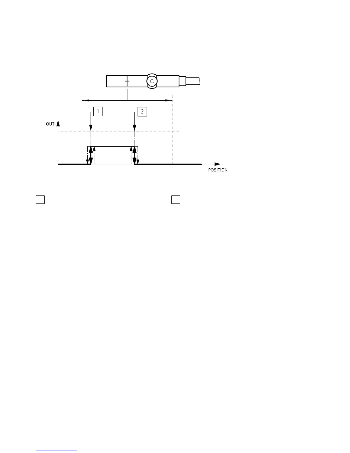
4.2.2 Window comparator
Output signal Hysteresis
1
Teach-in point 1
2
Teach-in point 2
Fig. 6 Window comparator
The teach-in points are linked to the window comparator function.
– The window width is determined by the position of the teach-in points.
– The hysteresis is preset and cannot be changed.
Function
12 Festo — SDAS-MHS — 2018-06
Page 13
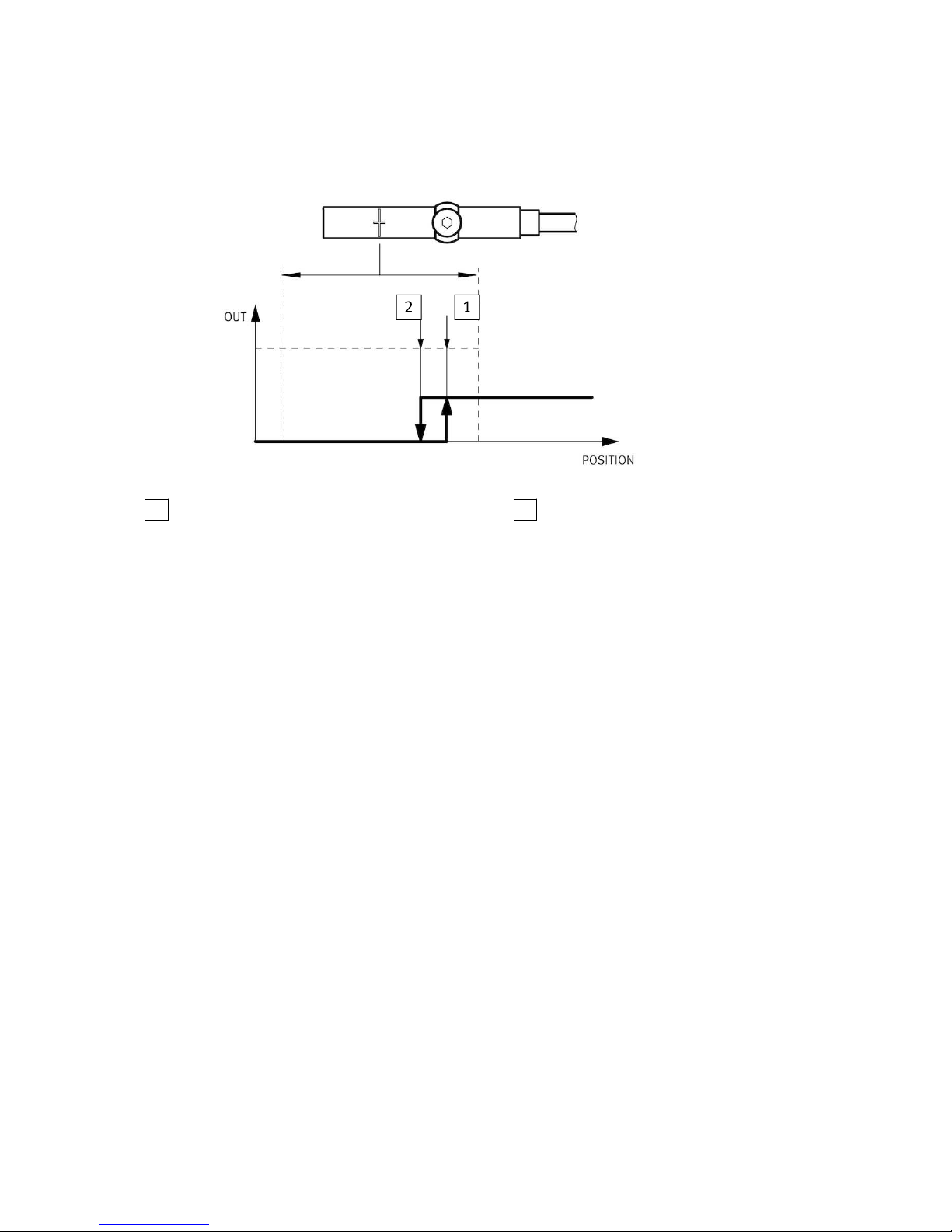
4.2.3 Hysteresis comparator
1
Teach-in point 1
2
Teach-in point 2
Fig. 7 Hysteresis comparator
The teach-in points are linked to the hysteresis comparator function.
– Teach-in point 1 is the switch-on point, teach-in point 2 is the reset point.
– The distance between teach-in point 1 and teach-in point 2 determines the size of the hysteresis.
Function
13Festo — SDAS-MHS — 2018-06
Page 14
4.2.4 Switching logic, normally open (NO) and normally closed (NC)
1
Normally open (NO)
2
Normally closed (NC)
Fig. 8 Inverting the SSC
The switching logic normally open (NO) is set as standard. The function of the SSC is inverted by
selecting the switching logic normally closed (NC).
4.3 Additional information on the operating modes
The binary data channels SSC1 and SSC2 for the position transmitter operating mode correspond to
the electrical switching outputs 1 and 2 for the cylinder switch operating mode.
Parameterising SSC1 and SSC2 via IO-Link makes it possible to use the window comparator and hysteresis comparator switching functions and the switching logic (NO/NC) in cylinder switch operating
mode too. Conversely, the switching points set in cylinder switch operating mode are directly available
in the position transmitter operating mode.
The switching logic for SSC1 set in the position transmitter operating mode applies to SSC1 and SSC2
in the cylinder switch operating mode, regardless of what has been set for SSC2.
An LED is available to display both switching outputs:
– Switching logic NC: the output signal for both switching outputs is AND-gated on the LED display.
– Switching logic NO: the output signal for both switching outputs is OR-gated on the LED display.
Function
14 Festo — SDAS-MHS — 2018-06
Page 15
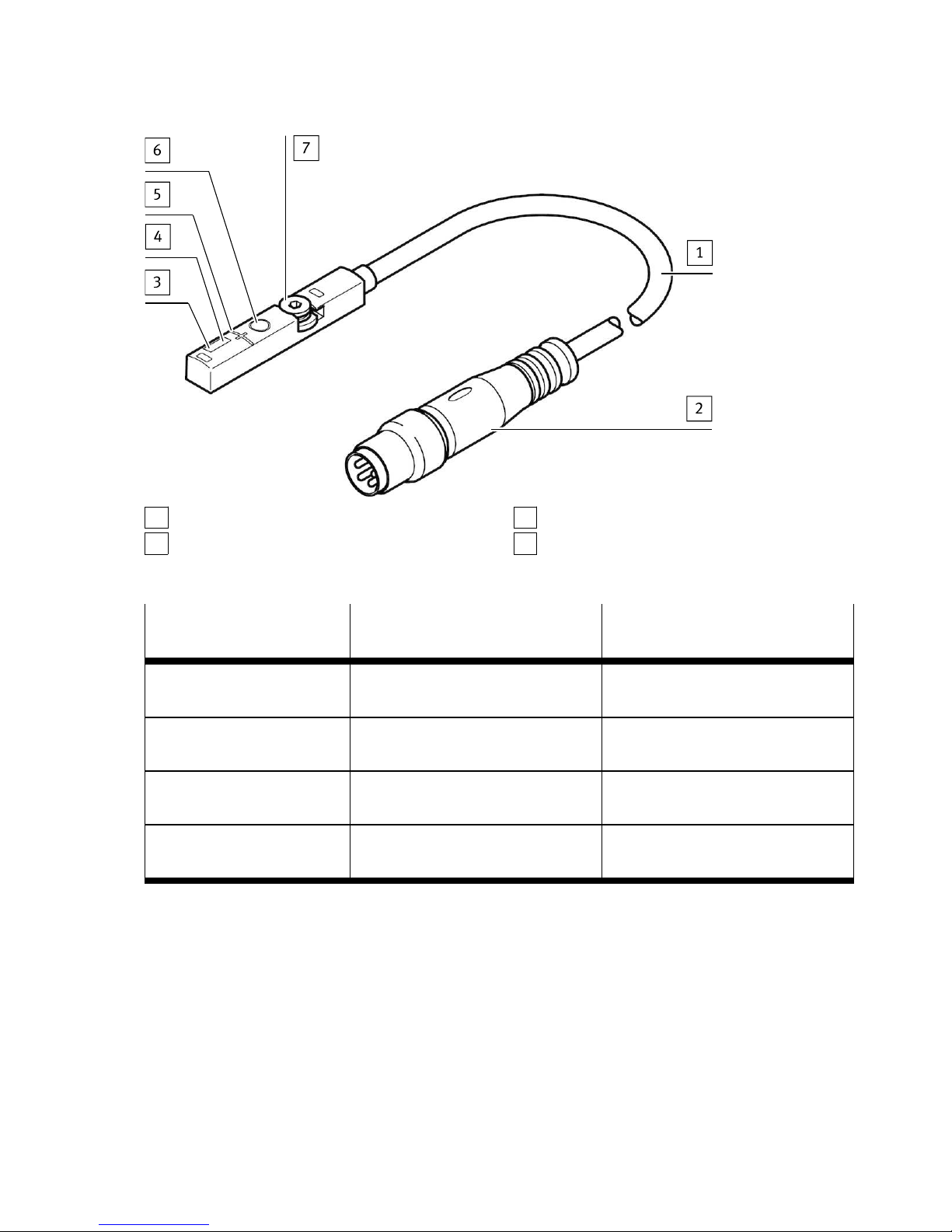
1
SSC1 = Switching output 1
2
SSC2 = Switching output 2
3
SSC3
4
SSC4
Fig. 9 Relationship of position transmitter and cylinder switch operating modes
Position transmitter Cylinder switch Switching logic in cylinder switch
operating mode
SSC 1
←→
Switching output 1 As set for SSC1
[or NO: factory setting]
SSC 2
←→
Switching output 2 As set for SSC1
[or NO: factory setting]
SSC 3 Ignored; settings remain in
memory
Ignored; setting remains in
memory
SSC 4 Ignored; settings remain in
memory
Ignored; setting remains in
memory
Tab. 2 Relationship between the operating modes
Function
15Festo — SDAS-MHS — 2018-06
Page 16
5 Installation
5.1 Electrical installation
WARNING!
Risk of injury due to electric shock.
• For the electrical power supply, use only PELV circuits in accordance with IEC 60204-1/EN 60204-1
(Protective Extra-Low Voltage, PELV).
• Observe the general requirements of IEC 60204-1/EN 60204-1 for PELV circuits.
• Only use voltage sources that ensure a reliable electric separation from the mains network in
accordance with IEC 60204-1/EN 60204-1.
1. Switch off operating voltage.
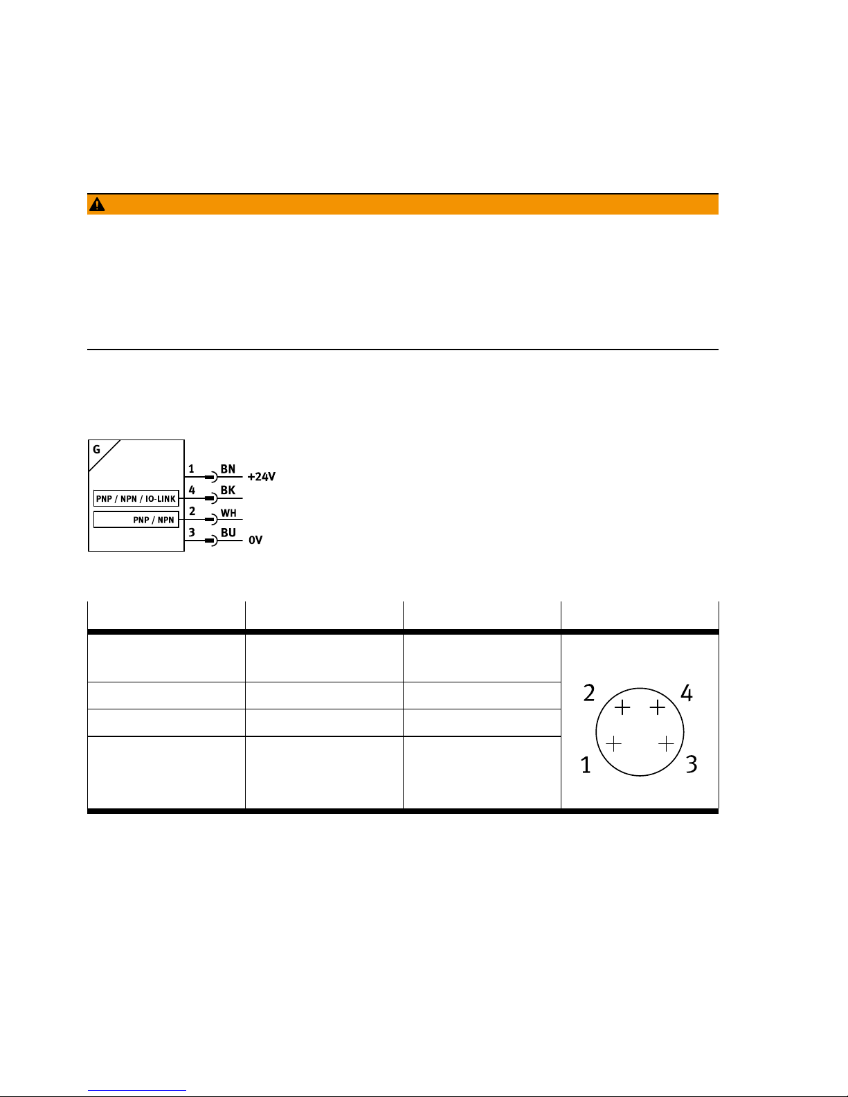
2. Connect the M8 plug to the connecting cable of the higher-order controller è Fig.11,4.
– Tightening torque for the union nut of the plug: max. 0.3Nm
Fig. 10 Circuit diagram
Pin Wire colour Allocation Plug
1 Brown (BN) Operating voltage
+24VDC
2 White (WH) Switching output 2
3 Blue (BU) 0V
4 Black (BK) Switching output 1
M8x1, 4-pin
Tab. 3 Pin allocation of plug connection for cylinder switch operating mode
Installation
16 Festo — SDAS-MHS — 2018-06
Page 17
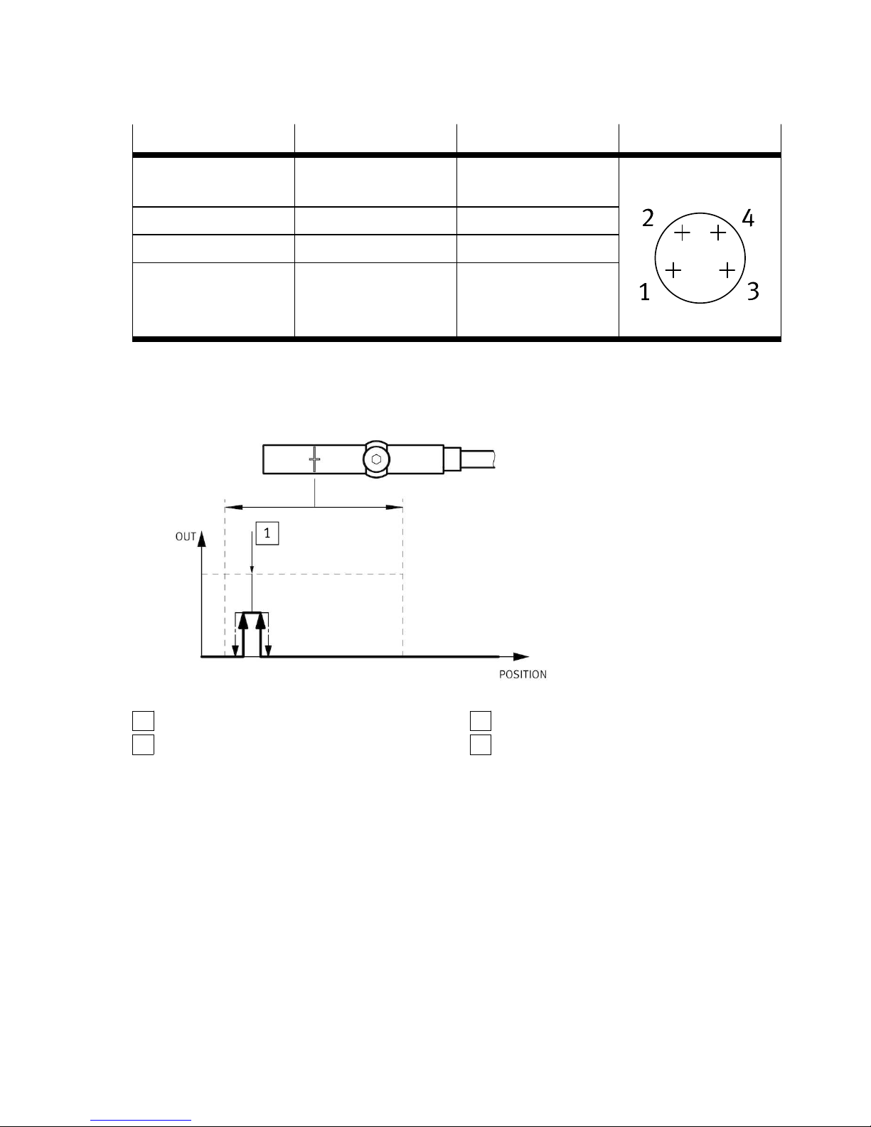
Pin Wire colour Allocation Plug
1 Brown (BN) Operating voltage
+24VDC
2 White (WH) Not used
3 Blue (BU) 0V
4 Black (BK) IO-Link
M8x1, 4-pin
Tab. 4 Pin allocation of plug connection for position transmitter operating mode
5.2 Mechanical installation
1
Hexagon socket spanner
2
Retaining screw
3
T-slot (profile slot 8)
4
M8 plug
Fig. 11 Mechanical installation
1. Insert the position transmitter into the T-slot of the drive.
2. Move the piston into an end position of the application.
3. Push the position transmitter in the direction of the piston until the red LED goes out.
4. Tighten the hexagon socket-head bolts (spanner size: 1.5mm).
– Tightening torque: max. 0.5Nm
6 Commissioning
• Switch on the operating voltage.
Ä
The position transmitter is ready for operation.
Commissioning
17Festo — SDAS-MHS — 2018-06
Page 18

6.1 Cylinder switch operating mode
The position transmitter is parameterised once it is installed.
• Be mindful of the surface temperature of the capacitive operating key and of the drive.
• Avoid contamination and moisture on the position transmitter.
6.1.1 Activating set-up mode
• Press the capacitive operating key 3 times within 3s.
Ä
Set-up mode active: yellow and red LEDs flash alternately.
If programming is not completed within 60s of starting set-up mode, the SDAS-MHS automatically
switches into the operating mode.
Commissioning
18 Festo — SDAS-MHS — 2018-06
Page 19
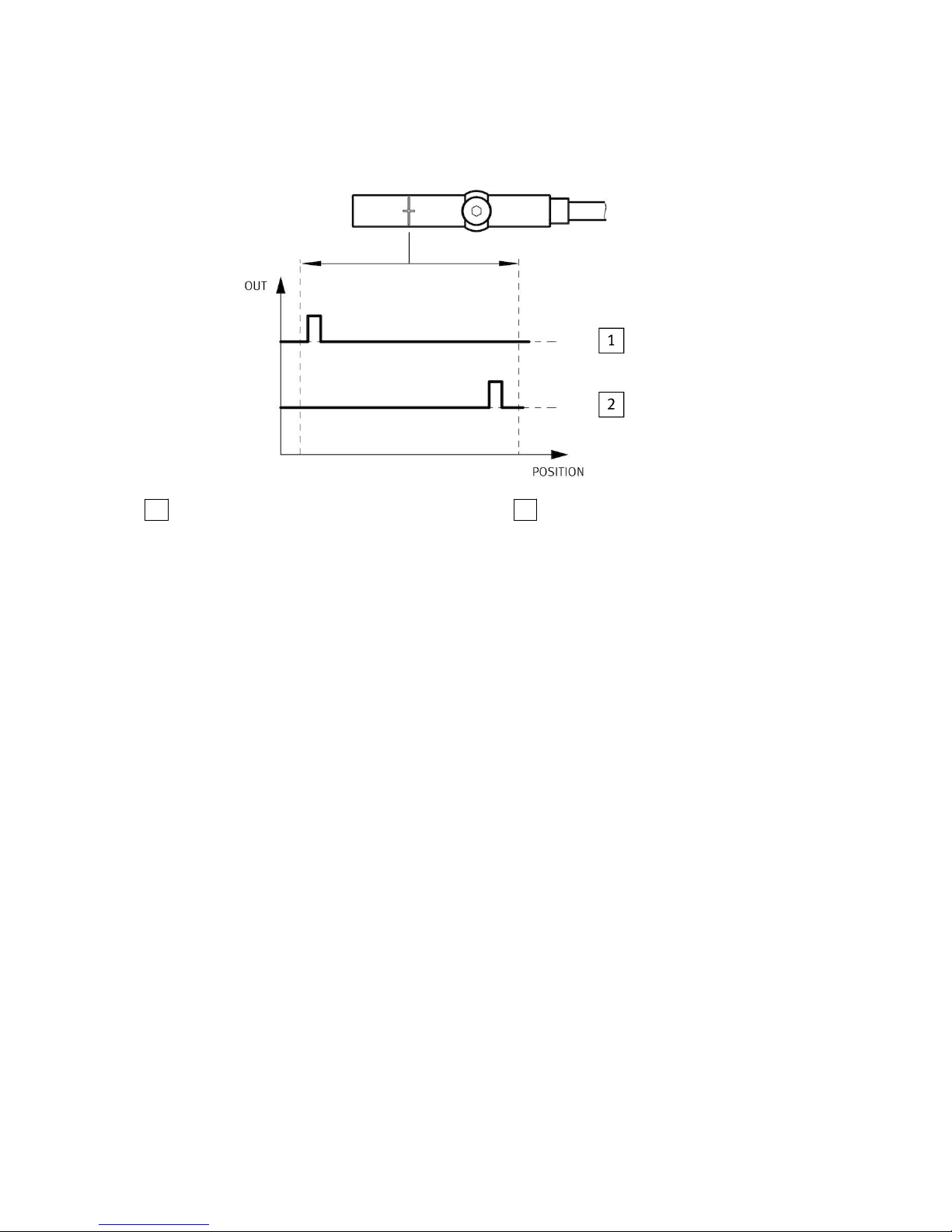
6.1.2 Set switching points
1
Electrical output 1
2
Electrical output 2
Fig. 12 Application example: Cylinder switch operating mode
1. Move piston to the desired position for switching output 1, within the sensing range.
Ä
Red LED OFF è Tab. 6 LED displays in the cylinder switch operating mode.
2. Activate set-up mode.
3. To assign the position for switching output 1, press the capacitive operating key 1 time.
Ä
The yellow LED flashes 1 time.
4. Press the capacitive operating key.
Ä
Switching point 1 is established. Operating mode is active.
5. Move piston to the desired position for switching output 2, within the sensing range.
Ä
Red LED OFF è Tab. 6 LED displays in the cylinder switch operating mode.
6. Activate set-up mode.
7. To assign the position for switching output 2, press the capacitive operating key 2 time.
Ä
The yellow LED flashes 2 times.
8. Press the capacitive operating key.
Ä
Switching point 2 is established. Operating mode is active.
6.1.3 Changing the configuration of the switching outputs
The switching outputs are configured as PNP as standard. Carry out the following steps to change the
configuration of the switching outputs:
1. Activate set-up mode.
2. To switch into the change-over mode, press the capacitive operating key 3 times.
Ä
The yellow LED indicates the current configuration (flashes 3x/2s pause).
– PNP: ON > Flashes > ON
– NPN: OFF > Flashes > OFF
3. To change the configuration, press the capacitive operating key 1 time.
Ä
Change to configuration is stored. Device is ready for operation.
Commissioning
19Festo — SDAS-MHS — 2018-06
Page 20
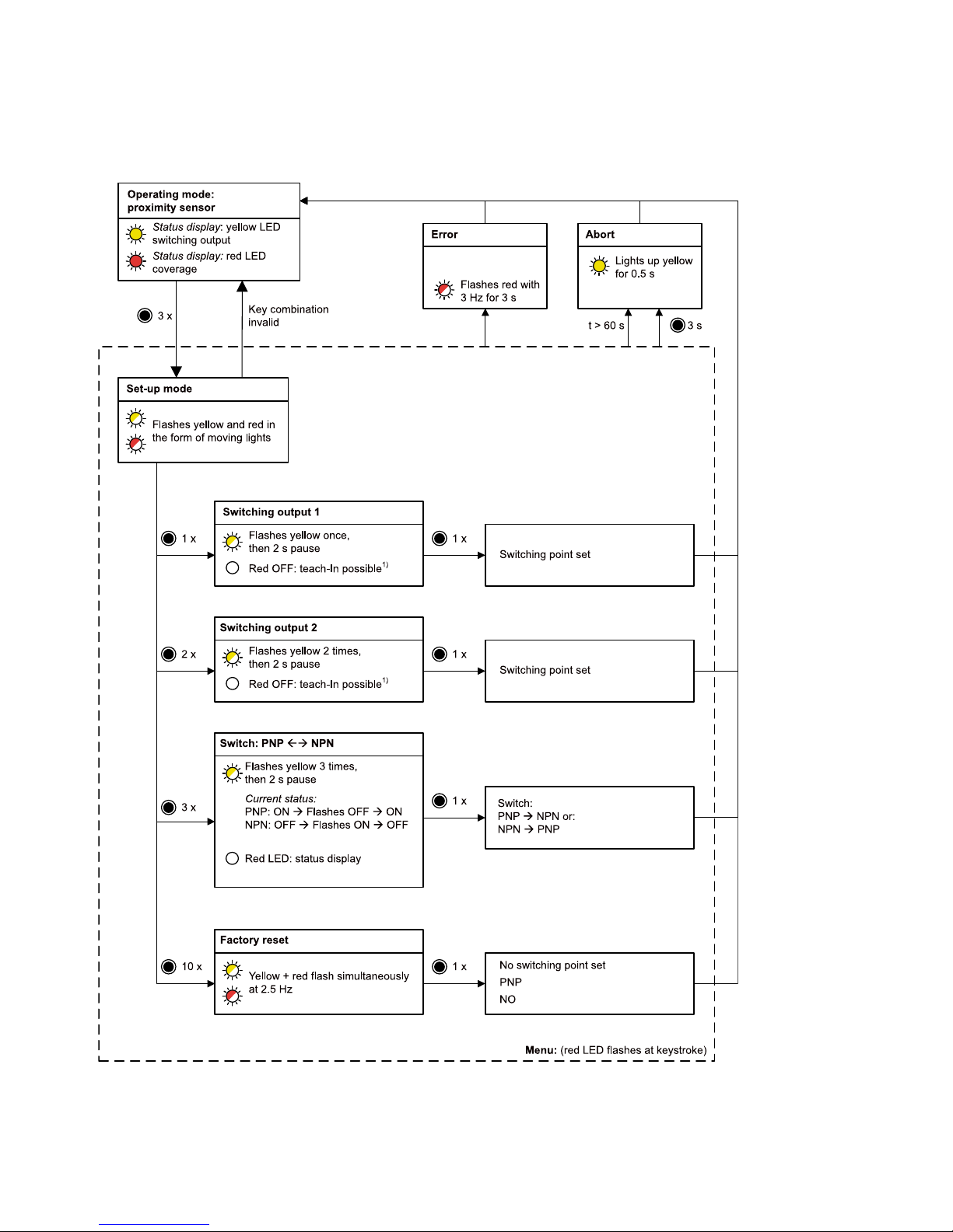
6.1.4 Menu structure
Fig. 13 Settings using the capacitive operating key (menu structure)
Commissioning
20 Festo — SDAS-MHS — 2018-06
Page 21
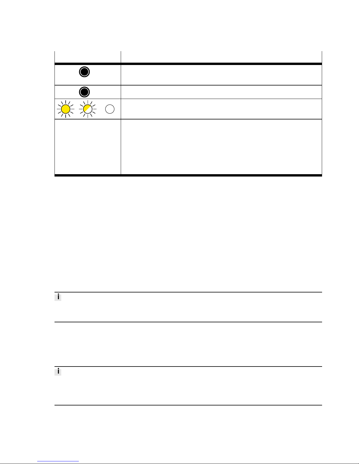
LED/operating key Meaning
N x Press the capacitive operating key (in the example: 3x); max. 1s pause
between 2 consecutive presses
3s Hold the capacitive operating key pressed for at least 3s.
LED illuminated / LED flashing / LED OFF (in the example: yellow LED)
1) A switching point can only be set when the red LED is OFF. When the red
LED is flashing at 1.5Hz, the magnet is located in the region of the operational reserve. It is not possible to set a switching point. The operational
reserve is required for the safe setting of switching points in the edge
region. When the red LED is illuminated, the magnet is outside the sensing
range. It is not possible to set a switching point.
Tab. 5 Explanation of symbols
6.2 Position transmitter operating mode
In the position transmitter operating mode, commissioning is carried out in the higher-order controller
of the IO-Link master.
1. Load the device description file IODD (èwww.festo.com/sp) into the interpreter of the IO-Link
master.
2. For general information on the IO-Link specification and for the Smart Sensor profile
èwww.io-link.com.
3. Connect the position transmitter to the IO-Link master as shown in the circuit
diagramè Tab. 4 Pin allocation of plug connection for position transmitter operating mode.
4. Program the position transmitter. Observe the instructions in the operating instructions for the IOLink master.
Errors during commissioning are displayed on the user interface of the IO-Link master. Programming is
blocked.
7 Operation
7.1 Cylinder switch operating mode
The position transmitter is parameterised once it is installed.
• Be mindful of the surface temperature of the capacitive operating key and of the drive.
• Avoid contamination and moisture on the position transmitter.
Operation
21Festo — SDAS-MHS — 2018-06
Page 22
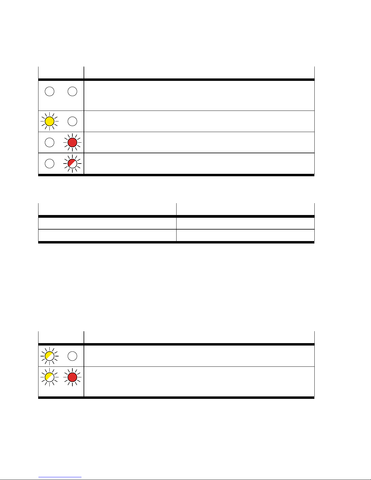
7.1.1 LED display
LED Meaning
Both LEDs OFF: status display.
– Piston within the sensing range
– No switching output set
Yellow LED illuminated: switching status display.
– Switching output 1 or switching output 2 is active.
Red LED illuminated: status display.
– Piston outside the sensing range
Red LED flashing at 1.5Hz: status display.
– Piston in the region of the operational reserve
Tab. 6 LED displays in the cylinder switch operating mode
7.1.2 Reset to factory setting
Parameter Factory setting
Switching points None
Switching outputs PNP
Tab. 7 Factory settings SDAS-MHS
Requirement: set-up mode is active.
1. Press the capacitive operating key 10 times.
Ä
Yellow and red LEDs flash at 2.5Hz.
2. Press the capacitive operating key.
Ä
Position transmitter is reset to factory settings. Operating mode is active.
7.2 Position transmitter operating mode
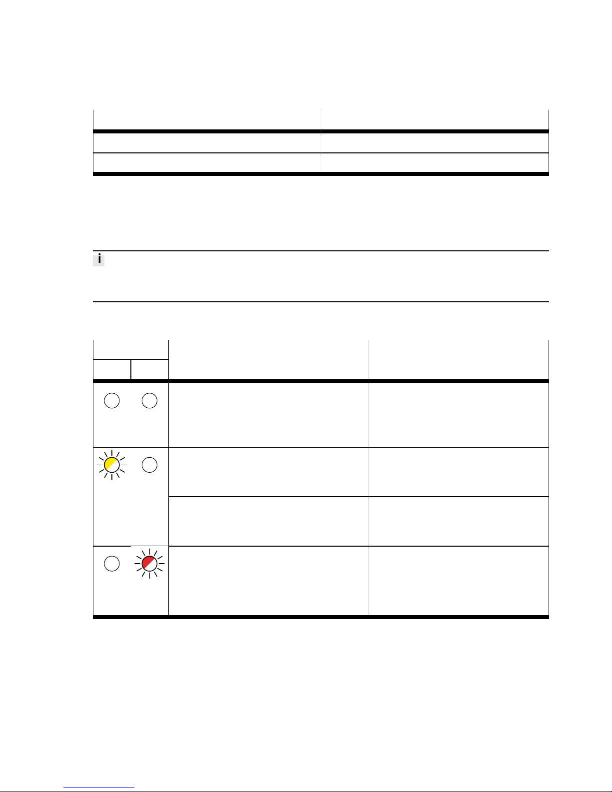
7.2.1 LED display
LED Meaning
Yellow LED flashing at 1Hz: ready status.
– IO-Link communication is active.
Red LED illuminated and yellow LED flashing: status display.
– IO-Link communication is active.
– Piston outside the sensing range
Tab. 8 LED displays in the position transmitter operating mode
Operation
22 Festo — SDAS-MHS — 2018-06
Page 23
7.2.2 Reset to factory setting
Parameter Factory setting
SSC channels Not programmed
PDV Minimum on the cable side
Tab. 9 Factory settings SDAS-MHS
The factory settings are reset via IO-Link.
8 Fault clearance
Errors during IO-Link operation are displayed on the user interface of the IO-Link master. The IO-Link
switching output is not blocked.
8.1 Diagnostics via LED
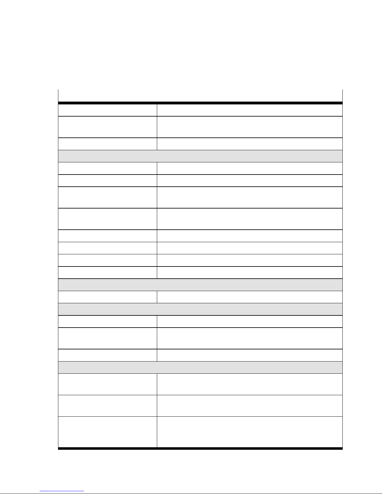
LED display Possible cause Remedy
Yellow Red
Both LEDs OFF
Power supply, connecting cable or sensor
is faulty/defective (there may not be a fault
è Tab. 6 LED displays in the cylinder
switch operating mode).
– Check power supply.
– Check connecting cable, replace if
necessary.
– Replace device.
Permanently:
Short circuit/overload at the switching output
– Eliminate short circuit/overload.
Yellow LED
flashing at
3Hz
For 3s, after pressing the capacitive operating key:
capacitive operating key is blocked.
– Cancel the block on the capacitive
operating key using the IO-Link.
Red LED flashing at 3Hz
Hardware error – Switch the power supply off and
then on again.
– Replace device.
Tab. 10 Diagnostics via LED display
Fault clearance
23Festo — SDAS-MHS — 2018-06
Page 24

8.2 General malfunctions
Fault description Cause Remedy
Drive is not suitable. Use a suitable drive.
Device is faulty. Replace device.
No power supply or impermissible operating voltage.
Comply with operating voltage
range.
Short circuit or overload at the
output
Eliminate short circuit/overload.
Magnetic objects in close proximity to the position transmitter
Avoid positioning magnetic
objects in close proximity.
Sensor/drive rotated by 180°
after initial commissioning.
Reset to factory settings (using
the operating key or via IOLink).
Incorrect or unexpected signals
at the output
Incorrect or unexpected signals
during initial commissioning on
grippers or in attachments
which are partly ferromagnetic
On initial commissioning, move
gripper jaws or pistons within
the sensing range (e.g. at both
end positions).
Short circuit or overload at the
output
Eliminate short circuit/overload.Switching output does not
switch in accordance with the
settings.
Device is faulty. Replace device.
Settings cannot be edited. Access protection is active. Unblock operating key (only
possible via IO-Link).
Capacitive operating key does
not react to input
Dirt or moisture on the position
transmitter
Wipe position transmitter with a
dry cloth.
Tab. 11
9 Disassembly
1. Switch off the power supply.
2. Disconnect connections from the position transmitter.
3. Undo the hexagon socket-head bolts è Fig.11.
4. Remove the position transmitter from the T-slot of the drive.
Disassembly
24 Festo — SDAS-MHS — 2018-06
Page 25
10 Technical data
10.1 General
SDAS-MHS
Approvals RCM
CE marking (declaration of conformity èwww.festo.com/sp)
In accordance with EU EMC Directive
Note on materials RoHS-compliant, halogen-free
Sensor system – General
Sensing range [mm] Max. 52
Ambient temperature [°C] –40…+80
Typical sampling interval
[ms] 2
Typical signal running
time
[ms] <4
Max. speed of travel [m/s] 3
Path resolution [mm] Max. 0.02
Repetition accuracy [mm] 0.2
Typical linearity error [mm] _1
Electronics – General
Operating voltage DC [V] 10…30
Electronics – Switching output
Switching output 2x PNP or 2x NPN, adjustable
Typical hysteresis of
switching output
[mm] ≤0.25 _0.05
Max. output current [mA] 50
1)
Electromechanics
Cable length [m] SDAS-MHS- … -0.3-M8: 0.3
SDAS-MHS- … -2.5-LE: 2.5
Nominal conductor
cross section
[mm"] 0.1
Ambient temperature
with flexible cable
installation
[°C] –20…+70
Technical data
25Festo — SDAS-MHS — 2018-06
Page 26
SDAS-MHS
Mechanics
Max. tightening torque [Nm] 0.6
Information on housing
materials
PA-reinforced
High-alloy stainless steel
Immission/emission
Degree of protection
(to EN60529)
IP65/IP68
1) Per switching output
Tab. 12 Technical data
10.2 IO-Link
SDAS-MHS
Protocol version Device V 1.1
Profile Smart sensor profile
Function classes 0x8000: Identification
0x8001: Switching signal channel (SSC)
0x8002: Process data variable (PDV)
0x8003: Diagnostics
0x8004: Teach channel
Communication mode COM2
Process data width IN 2 bytes
Port class A, 4-pin
Device-ID 0x00000C
Tab. 13 Physical layer
Process data Record: 2 Byte
Bit 15 … 4 3 2 1 0
Process
data
Process Data Variable (PDV)
è Tab. 15 PDV (Process Data
Variable): Position signal.
SSC4
1)
SSC3
1)
SSC2
1)
SSC1
1)
Data Position switch 4 switch 3 switch 2 switch 1
Type Unsigned Integer BooleanT
1) Switching signal channel
Tab. 14 Process data content
Technical data
26 Festo — SDAS-MHS — 2018-06
Page 27

PDV (Dec) PDV (Hex) Description
0 0x000 Outside the sensing range (Out
of Range)
1
…
3999
0x001
…
0xF9F
Within the sensing range, valid
position signal
4000 0xFA0 Outside the sensing range (Out
of Range)
4080 0xFF0 PDV Error
4095 0xFFF Out of Range
Tab. 15 PDV (Process Data Variable): Position signal
SSC (Switching Signal Channel): Switching function
Index Sub-Index Access Parameter
Name
Values Data type
0x0002 (2) 0 W Standard Com-
mand
See table
above
UIntT8
0x000C (12) 0 R/W Device Access
Locks
0: unlocked
(default)
1: locked
Bit 1: Data
Storage Access
Bit 3: Local
User Interface
(Button)
UInt16
0x0010 (16) 0 R Vendor Name Festo AG &
Co.KG
String 64 Byte
0x0011 (17) 0 R Vendor Text http://www.
festo.com
String 64 Byte
0x0012 (18) 0 R Product Name SDAS-MHS-
M40-1L-PNLKPN-E-0.3-M8
String 64 Byte
0x0013 (19) 0 R Product ID 8063974 String 64 Byte
0x0014 (20) 0 R Product Text Position-Trans-
mitter
String 64 Byte
0x0016 (22) 0 R Hardware Revi-
sion
REVxy String 64 Byte
Technical data
27Festo — SDAS-MHS — 2018-06
Page 28

Index Sub-Index Access Parameter
Name
Values Data type
0x0017 (23) 0 R Firmware Revi-
sion
REVxy String 64 Byte
0x0018 (24) 0 R/W Application
Specific Tag
Value is freely
defined by
user
String 32 Byte
0x0028 (40) 0 R Process Data
Input
See PDV Record 2 Byte
Tab. 16 Service data
Index Sub-Index Access Parameter
Name
Values Data type Comment
01 RW Setpoint 1 216…3784 IntT160x003C (60)
02 RW Setpoint 2 216…3784 IntT16
01 RW Switchpoint
logic
0 = NO, normally open
1 = NC, normally closed
UIntT8
02 RW Switchpoint
mode
0 = Deactivated
134 = Cylinder switch
133 = Window comparator
3 = Hysteresis comparator
UIntT8
0x003D (61)
03 RW Hysteresis 30 UIntT16
SSC1
01 RW Setpoint 1 216…3784 IntT160x003E (62)
02 RW Setpoint 2 216…3784 IntT16
0x003F (63) 01 RW Switchpoint
logic
0 = NO, normally open
1 = NC, normally closed
UIntT8
SSC2
Technical data
28 Festo — SDAS-MHS — 2018-06
Page 29

Index Sub-Index Access Parameter
Name
Values Data type Comment
02 RW Switchpoint
mode
0 = Deactivated
134 = Cylinder switch
133 = Window comparator
3 = Hysteresis comparator
UIntT80x003F (63)
03 RW Hysteresis 30 UIntT16
SSC2
01 RW Setpoint 1 216…3784 IntT160x4000
(16384)
02 RW Setpoint 2 216…3784 IntT16
01 RW Switchpoint
logic
0 = NO, normally open
1 = NC, normally closed
UIntT8
02 RW Switchpoint
mode
0 = Deactivated
134 = Cylinder switch
133 = Window comparator
3 = Hysteresis comparator
UIntT8
0x4001
(16385)
03 RW Hysteresis 30 UIntT16
SSC3
01 RW Setpoint 1 216…3784 IntT160x4002
(16386)
02 RW Setpoint 2 216…3784 IntT16
SSC4
Technical data
29Festo — SDAS-MHS — 2018-06
Page 30

Index Sub-Index Access Parameter
Name
Values Data type Comment
01 RW Switchpoint
logic
0 = NO, normally open
1 = NC, normally closed
UIntT8
02 RW Switchpoint
mode
0 = Deactivated
134 = Cylinder switch
133 = Window comparator
3 = Hysteresis comparator
UIntT8
0x4003
(16387)
03 RW Hysteresis 30 UIntT16
SSC4
Tab. 17 Configuration by inputting parameters
Inverting the process data
Index Sub-Index Access Parameter
Name
Allowed Val-
ues
Data type
0x3100
(12544)
0 RW Invert the dir-
ection of the
position value
0 = PDV stand-
ard: Minimum
value at cable
side
1 = PDV inver-
ted: Maximum
value at cable
side
UIntT8
Tab. 18 Inverting the process data
Technical data
30 Festo — SDAS-MHS — 2018-06
Page 31

Error and warning messages via IO-Link
Code Type Name Description
0x4210 (16912) Warning Overtemperature
0x5000 (20480) Error Device hardware fault Device Exchange
0x5111 (20753) Warning Primary supply voltage
under-run
Check tolerance
0x6320 (25376) Error Parameter error Check data sheet and
values
0xFF91 (65425) Notification Data Storage Upload
Request
Tab. 19 Events
Code Additional Code Name Description
0x00 (0) Device application error
- no details
Service has been
refused by the device
application and no
detailed information of
the incident is available
0x11 (17) Index not available Access occurs to a not
existing index
0x12 (18) Subindex not available Access occurs to a not
existing subindex
0x20 (32) Service temporarily not
available
Parameter is not
accessible due to the
current state of the
device application
0x21 (33) Service temporarily not
available - local control
Parameter is not
accessible due to an
ongoing local operation
at the device
0x22 (34) Service temporarily not
available - device control
Parameter is not
accessible due to a
remote triggered state
of the device application
0x80 (128)
0x23 (35) Access denied Write access on a read-
only parameter
Technical data
31Festo — SDAS-MHS — 2018-06
Page 32

Code Additional Code Name Description
0x30 (48) Parameter value out of
range
Written parameter
value is outside its permitted value range
0x31 (49) Parameter value above
limit
Written parameter
value is above its specified value range
0x32 (50) Parameter value below
limit
Written parameter
value is below its specified value range
0x33 (51) Parameter length over-
run
Written parameter
length is above its predefined length
0x34 (52) Parameter length
underrun
Written parameter
length is below its predefined length
0x35 (53) Function not available Written command is not
supported by the
device application
0x36 (54) Function temporarily
unavailable
Written command is not
available due to the
current state of the
device application
0x40 (64) Invalid parameter set Written single paramet-
er collides with other
actual parameter settings
0x41 (65) Inconsistent parameter
set
Parameter inconsistencies were found at the
end of block parameter
transfer, device plausibility check failed
0x80 (128)
0x82 (130) Application not ready Read or write service is
refused due to a temporarily unavailable
application
Technical data
32 Festo — SDAS-MHS — 2018-06
Page 33

Code Additional Code Name Description
0x01 (1) Error: Index not read-
able
0x02 (2) Parameter write access
is locked
0x10 (16) Position OutOfRange Magnet Position is out
of range
0x81 (129)
0x11 (17) Position OutOfTeach Teach Area is between
216 and 3784 digits
Tab. 20 Error Types
Resetting the position transmitter to factory setting
Index Sub-Index Access Parameter
Name
Values Data type
0x0002 (2) 0 W Standard Com-
mand
130 = Restore
Factory Settings
UIntT8
Tab. 21 Factory setting
Technical data
33Festo — SDAS-MHS — 2018-06
Page 34

I-Port
Index Sub-Index Name Access Length (Byte) Default Value
0x0040 0x00 Device attrib-
utes
R/W 1 0x00
1)
0x0041 0x00 Extended para-
meters
R/W 2 0x0000
1)
0x0042 0x00 Diagnosis
parameter
R 2 0x0000
1)
0x0043 0x00 Device specific
parameters
R/W 8 è Tab. 23 I-
Port: Device
specific
parameters
2)
0x00FE 0x00 I-Port Revision R/W 2 0x0101
1)
1) Only default value possible
2) For permitted value ranges for individual parameters see BDA or IODD.
Tab. 22 I-Port: Overview of parameters
Byte 1 2 3 4 5 6 7 8
IO-Link
index
0x003C 0x003D
Subindex 1 2 1 2 3
Function SP1 SP2 Logic Mode HY
Byte high low high low
– –
high low
Default
values
0x00 0xAF 0x00 0xAF 0x00 0x00 0x00 0x05
Tab. 23 I-Port: Device specific parameters
Technical data
34 Festo — SDAS-MHS — 2018-06
Page 35

Page 36

Reproduction, distribution or sale of this document or communication of its contents to others without express authorization is
prohibited. Offenders will be liable for damages. All rights
reserved in the event that a patent, utility model or design patent
is registered.
Copyright:
Festo AG & Co. KG
73734 Esslingen
Ruiter Straße 82
Germany
+49 711 347-0
+49 711 347-2144
Fax:
www.festo.com
Internet:
Phone:
e-mail:
 Loading...