

Page 1
Manual
8077991
2017-11
[8077993]
SBRD
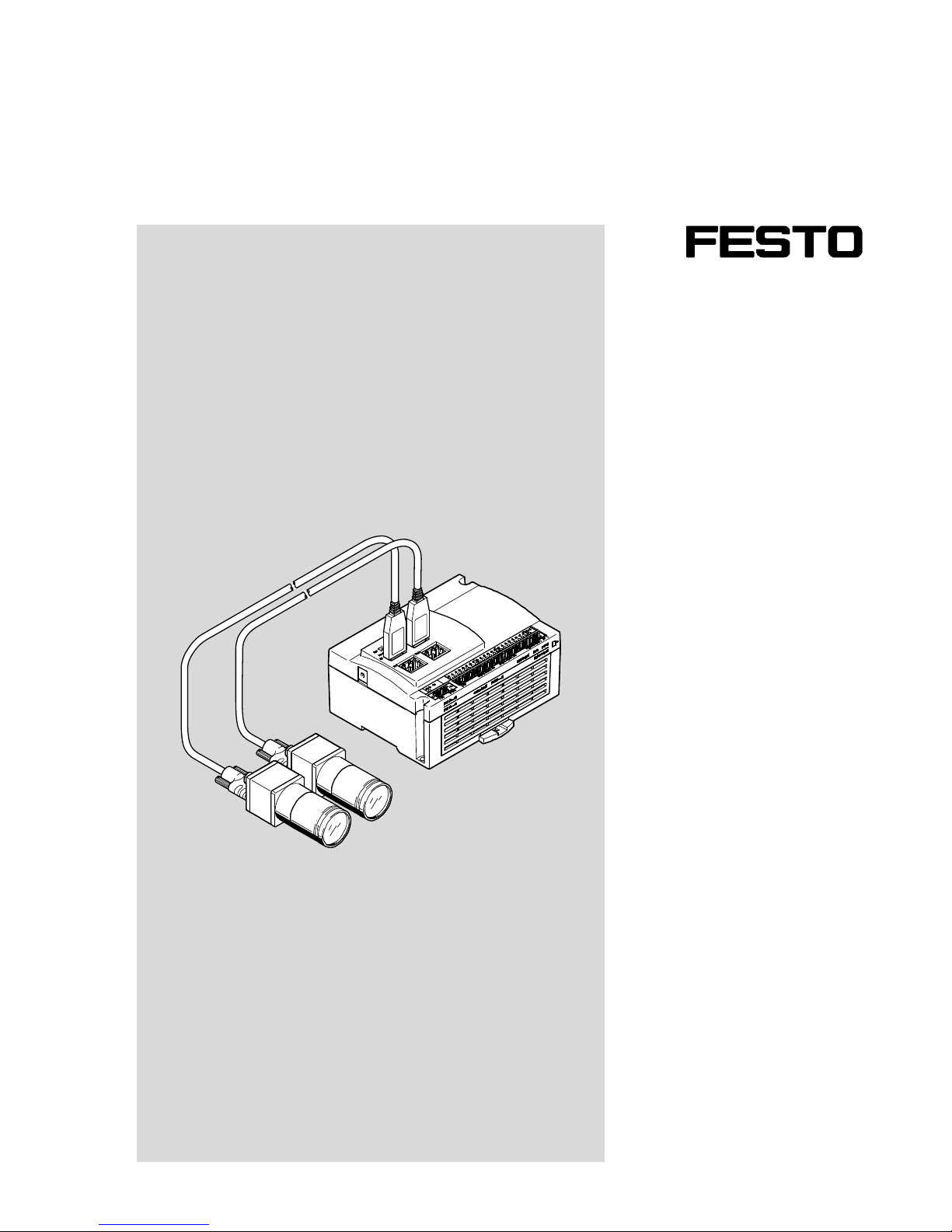
Camera System
Page 2
SBRD
2 Festo – SBRD-EN – 2017-11 –
Translation of the original instructions
SBRD-EN
Identification of hazards and instructions on how to prevent them:
Danger
Immediate dangers which can lead to death or serious injuries
Warning
Hazards that can cause death or serious injuries
Caution
Hazards that can cause minor injuries
Other symbols:
Note
Material damage or loss of function
Recommendations, tips, references to other documentation
Essential or useful accessories
Information on environmentally sound usage
Text designations:
Activities that may be carried out in any order
1. Activities that should be carried out in the order stated
– General lists
è Result of an action/References to more detailed information
Page 3

SBRD
Festo – SBRD-EN – 2017-11 – English 3
Table of Contents – SBRD
Information regarding this description 5..............................................
Product identification, versions 5....................................................
Product label 5..................................................................
Service 5.......................................................................
Product specific terms and abbreviations 6............................................
1 Safety 8..................................................................
1.1 General safety information 8..................................................
1.2 Intended use 9.............................................................
1.2.1 Range of applications and certifications 9...............................
1.3 Training of skilled personnel 9.................................................
1.4 Range of application and certifications 9........................................
2 Further information 10.......................................................
3 System overview 11..........................................................
3.1 Design and mode of operation of the SBRD camera system 11........................
3.1.1 Components 11.....................................................
3.1.2 Areas of application 11...............................................
3.1.3 Functional principle 11...............................................
3.2 Variants 12.................................................................
3.3 Software packages 15........................................................
3.4 Accessories 15..............................................................
4 Assembly 16...............................................................
4.1 Mounting of the camera system 17..............................................
4.1.1 Mounting of the SBRD-Q controller 17...................................
4.1.2 Mounting of SBPB camera head 17.....................................
4.1.3 Mounting of NEBC connecting cable 17..................................
4.2 Dimensions of SBRD camera system 18..........................................
4.2.1 SBRD-Q controller 18................................................
4.2.2 SBPB camera head 19................................................
5 Installation 20..............................................................
5.1 General installation instructions 20..............................................
5.1.1 Selecting the power pack 21...........................................
5.2 Electrical connections 22......................................................
5.2.1 Connection of the operating voltage supply and the I/Os 22..................
5.2.2 Connecting the Ethernet interface 23....................................
5.2.3 Connecting the camera 24............................................
Page 4

SBRD
4 Festo – SBRD-EN – 2017-11 – English
6 Commissioning 25...........................................................
6.1 Information on commissioning 25...............................................
6.2 Firewall settings on the PC 25..................................................
6.3 Selection of the evaluation mode 26.............................................
6.3.1 I/O process with triggered evaluation mode 27............................
6.3.2 I/O process with free wheel unit evaluation mode 28.......................
6.4 Connection to higher-order controller 30.........................................
6.4.1 General information on use of inputs 31..................................
6.4.2 Use of the Ethernet interface with Telnet 33...............................
6.4.3 Telnet commands 36.................................................
6.4.4 Messages and error descriptions 39.....................................
6.4.5 Use of the Ethernet interface with Telnet streaming 40......................
6.4.6 Use of the Ethernet interface with Telnet XML 41...........................
6.5 Notes for operation 47........................................................
7 Diagnostics and error handling 48..............................................
7.1 General diagnostics options 48.................................................
7.1.1 Status indication 48.................................................
7.1.2 Error handling 51....................................................
G.2 Cleaning and maintenance 54..................................................
G.3 Siemens star 55.............................................................
A Technical appendix 56........................................................
A.1 Technical data 56............................................................
A.2 Error messages 63...........................................................
A.3 Address table for Telnet and Telnet-XML 64.......................................
A.3.1 Input register 64....................................................
A.3.2 Output register 64...................................................
A.3.3 Quick access to input and output register 65..............................
A.3.4 Extended system status/system information 65...........................
A.3.5 System time of the device 66..........................................
A.3.6 Overall tolerance of the type in the current job 66..........................
A.3.7 Basic results of the last test 67.........................................
A.3.8 Freely usable flag words (not remanent) 68...............................
A.3.9 Configure cameras 68................................................
A.3.10 Characteristics – results of the last test 69...............................
A.3.11 Job parameter 71....................................................
Page 5
SBRD
Festo – SBRD-EN – 2017-11 – English 5
Information regarding this description
For all available product documentation è www.festo.com/pk
Product identification, versions
This documentation refers to the following versions:
Software Version
Firmware SBRD-Q Version 1.0.0 and higher
Camera Configuration Studio CCS Version 1.0 and higher
Festo Field Device Tool Version 2.7 and higher
Tab. 1 Hardware and software versions
This description contains general basic information on mounting, installation and operation of the cam
era system. Further information on commissioning, parameterisation and diagnostics can be found
in the help system of the software package and at è www.festo.com/sp.
Type Title Table of contents
Description of electronics Description of SBRD camera
system
Mounting, installation and
commissioning of the camera system
Help system Help for CCS software Functional description and operation
of CSS software
Help system Help for FFT software Software package for setting
the network characteristics and
downloading of firmware
Tab. 2 Documentation for the camera system
Product label
The following warning symbols are located on the front side of the product:
Observe corresponding information in the documentation.
Service
Contact your regional Festo contact if you have technical questions è www.festo.com.
Page 6
1 SBRD
6 Festo – SBRD-EN – 2017-11 – English
Product specific terms and abbreviations
The following product-specific abbreviations are used in this description:
Term/abbreviation
Meaning
Auto MDI-X Detects the Ethernet configuration of the remote station and
automatically adjusts the transmission and reception cable of a network
connection.
Bus node Provide the connection to specific fieldbuses. Transmit control signals to
the connected modules and monitor their ability to function
CCS Camera
Configuration Studio
PC software for configuration, commissioning and creation of jobs
Depth of field è Depth of focus
Depth of focus Space before and behind the object focused on that is also still perceived
as depicted sharp (also called depth of field). Depth of focus depends
on the focal length of the lens and the set orifice. Short focal lengths
with small orifice openings result in larger depth of focus.
Edge controlled Detection of a signal (e.g. input) reacts to the rising or falling edge.
Ethernet Physical protocol and network for connecting various devices
EtherNet/IP Communication standard via TCP/IP in automation technology
Exposure time Time in which the sensor is subject to light in image acquisition.
The longer the exposure time is, the more light that penetrates. Selection
of the exposure time depends, for example, on the speed of movement,
the available light and the light-sensitivity of the sensor. For moving
objects, exposure times that are too long cause blurred images.
Falling edge Transition from logic 1 to logic 0 (falling)
Feature Tools of a job determine characteristics in a photo. A characteristic result
can be a number, text or an image.
FFT – Festo Field Device
Tool
Software package for setting the network characteristics and
downloading of firmware
Focal length Long focal lengths generate a large image, while short focal lengths
create a wide-angle image. Lenses with changeable focal length are
designated zoom lenses. Lenses with longer focal lengths normally have
a lower sharpness and lower light intensity.
I Digital input
Image sensor Sensor
I/Os Digital inputs and outputs
Job Configuration of a testing task. Contains the settings performed by
the user of the cameras, tools, I/Os and job parameters used.
Logic 0, logic 1 Status of the input or output: logic 0 = 0 V, logic 1 = 24 V. (factory setting,
logical status è Section 3.1.3).
Page 7

1 SBRD
Festo – SBRD-EN – 2017-11 – English 7
Term/abbreviation Meaning
O Digital output
Orifice Opening through which light reaches the sensor through a lens element.
The larger the opening or orifice, the more light reaches the sensor.
Opening the orifice lowers the depth of focus. The depth of focus
increases as the orifice is closed (larger number of orifices). Smaller
orifice openings make longer exposure times necessary. Short exposure
times require larger orifice openings.
PLC/IPC Programmable logic controller/industrial PC
Protocol-based I/O Output of selected results for communication with controllers or robots
for graphic display or recording of production data
Rising edge Transition from logic 0 to logic 1 (rising).
Sensor Optoelectronic image sensor (e.g. CMOS image sensor), which converts
light signals into electrical signals. Besides the pure sensor function,
additional functions for image conversion, such as lighting control and
contrast correction, can be integrated directly into the chip.
Status-controlled Detection of a signal (e.g. input) reacts to a logic 1 or logic 0.
TCP/IP Combination of the protocols TCP and IP, the most-used protocol
for communication via Ethernet.
Telnet Client-server protocol for general, bidirectional communication, using
TCP. Telnet is normally used to offer users access to Internet research
through the command line.
Tool Tools determine selected characteristics in a photo.
XML Extensible markup language;
Markup language for representation of hierarchically structured data
in the form of text data
Tab. 1 Product-specific terms and abbreviations
Page 8

1 Safety
8 Festo – SBRD-EN – 2017-11 – English
1 Safety
1.1 General safety information
– In commissioning and programming, the safety regulations in this manual and in the documentation
for the controller used and for the other components must always be observed.
– Electrostatically sensitive devices! Electrostatic charges can damage the internal electronics.
– Never unplug or plug in a product when it is energised! Observe the handling specifications for elec
trostatically sensitive devices.
– Before mounting and installation work, switch off supply voltage. Only switch on the supply voltage
again when mounting and installation work are complete.
– The product can generate high frequency malfunctions, which may make it necessary to implement
interference suppression measures in residential areas.
Page 9
1 Safety
Festo – SBRD-EN – 2017-11 – English 9
1.2 Intended use
The SBRD camera system is intended for installation in a machine or automated system. It is used to
analyse parts for quality and position, detect their rotational position, pick & place, measuring, reading
of bar codes and data matrix codes (1D and 2D codes), reading of plain text (optical character
recognition).
Use the SBRD camera system only as follows:
– As intended
– In its original state without unauthorised modifications.
– Only with accessories released by Festo.
– In excellent technical condition.
When connected with commercially available components, such as sensors and actuators, the specified
limits for pressures, temperatures, electrical data, torques etc. must be observed.
The device is intended exclusively for use in an industrial environment. Measures for interference sup
pression may be required in residential areas.
1.2.1 Range of applications and certifications
Standards and test values, which the product complies with and fulfils, can be found in the “Technical
data” section (è Appendix A.1). The product-relevant EC directives can be found in the declaration of
conformity.
Note
Certificates and the declaration of conformity for this product are contained
in separate documents è www.festo.com/spareparts.
1.3 Training of skilled personnel
Only qualified personnel may carry out installation, commissioning, servicing and removal of
the product. The qualified personnel must be familiar with installation of electrical control systems.
1.4 Range of application and certifications
The product fulfils the requirements of EC directives and is marked with the CE marking.
Page 10

2 Further information
10 Festo – SBRD-EN – 2017-11 – English
2 Further information
Accessories è www.festo.com/catalogue.
Spare parts è www.festo.com/spareparts.
Page 11

3 System overview
Festo – SBRD-EN – 2017-11 – English 11
3 System overview
3.1 Design and mode of operation of the SBRD camera system
3.1.1 Components
The SBRD camera system consists of the following pneumatic components:
– Machine vision controller SBRD-Q
– SBPB camera heads
– NEBC connecting cables
3.1.2 Areas of application
The SBRD camera system can be used for the following problems:
– Position and rotational position detection
– Pick and Place
– Quality inspection
– Measurement
– Reading of bar codes and data matrix codes (1D and 2D codes)
– Reading of plain text (OCR)
3.1.3 Functional principle
The SBRD-Q controller actuates the connected camera heads to take pictures. The pictures taken are
transmitted and evaluated in the SBRD-Q controller, depending on the current operating mode and
the settings of the current job. The results of the evaluation are then output.
The sequence is determined by the current operating mode and the settings in the job, especially by
the evaluation mode.
Operating modes of the device
– Run mode: normal operating mode. A job stored on the device is executed.
– Configuration mode: limited operating mode for commissioning the device. This takes place
with the help of the CCS software. The first configuration is designated as job.
Evaluation modes, specified in the job:
– Triggered: single frame shooting and evaluation with each valid trigger signal.
– Free wheel unit: continuous image recording as long as the trigger signal is present.
A job contains all settings for conducting a specific function in an evaluation. During commissioning,
the user creates a job with the help of the CCS software. The job is then transmitted to a memory
location in the device.
A job contains the following settings:
– Job parameters (especially evaluation mode).
– Selection and settings of:
– Cameras used (e.g. type code, exposure time).
– Tools and their inspection features (e.g. distances, angles, X/Y positions. ID codes, text, image-
related results).
– Tolerance ranges for inspection features (e.g. min./max. rules).
Page 12
3 System overview
12 Festo – SBRD-EN – 2017-11 – English
– Digital I/O (24 V I/O with signal specifications).
– Protocol-based I/O (e.g. fieldbus protocols, graphic displays).
In the run mode, the device performs an evaluation based on the selected job. This results in the follow
ing sequence:
1. Image acquisition with the help of the camera heads.
2. Calculation of the (test) characteristics by the tools.
3. Comparison of the inspection features with the specified tolerance ranges.
4. Output of the results to the digital I/O.
5. Output of the results through the protocol-based I/O.
6. Output of diagnostic data, if applicable.
An evaluation can now be performed.
3.2 Variants
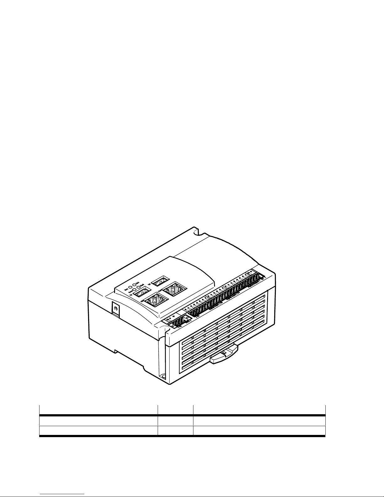
SBRD-Q controller
The SBRD-Q controller is a compact evaluation unit with degree of protection IP 20. Up to 2 cameras of
the SBPB model series can be connected to the device.
Fig. 3.1 SBRD-Q controller
Feature Code Value
Control SBRD Series D
Function Q Quality inspection
Tab. 3.1 Order code
Page 13
3 System overview
Festo – SBRD-EN – 2017-11 – English 13
Note
With EMC influence, individual malfunctions in the data transmission paths can occur.
This can influence the maximum data throughput.
Plan for corresponding reserves.
Characteristics of the SBRD-Q controller
24 V I/Os: 10 inputs + 2 inputs (pull-up resistor)/8 outputs
Power: 2x 32 bit ARM Cortex-A9 CPU
Memory: 1 GB
Dimensions: 130 mm x 106 mm x 60 mm
Function: machine vision
Communication: Ethernet 10/100/1000 Mbit/s
Interfaces: pluggable connectors
Camera interface: 2x USB-compatible for connection to the camera head
LED: status, I/Os, Ethernet
SD memory card slot
SBPB camera head
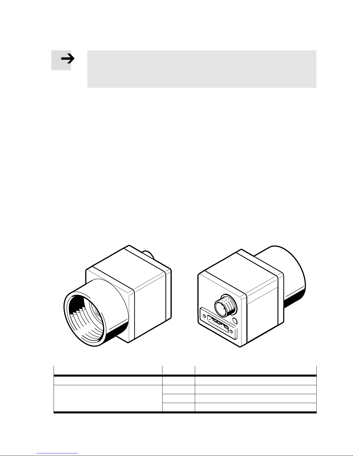
The SBPB camera heads are intended for image acquisition within the SBRD camera system. The ca
mera heads are optimised for use in an industrial environment. The product is available with image
sensors as colour and monochrome variants in various resolutions.
Fig. 3.2 SBPB camera head
Feature Code Value
Camera heads [SBPB] Series B
Resolution [R2] 1280x1024
[R5] 1600x1200
[R9] 2456x2054
Page 14
3 System overview
14 Festo – SBRD-EN – 2017-11 – English
Feature ValueCode
Image sensor [B] Monochrome
[C] Colour
Communication interface [U3] USB compatible
Digital inputs [1E] 1 input
Digital outputs [1A] 1 output
Lens connection [C] C mount
Tab. 3.2 Order code
NEBC connecting cables
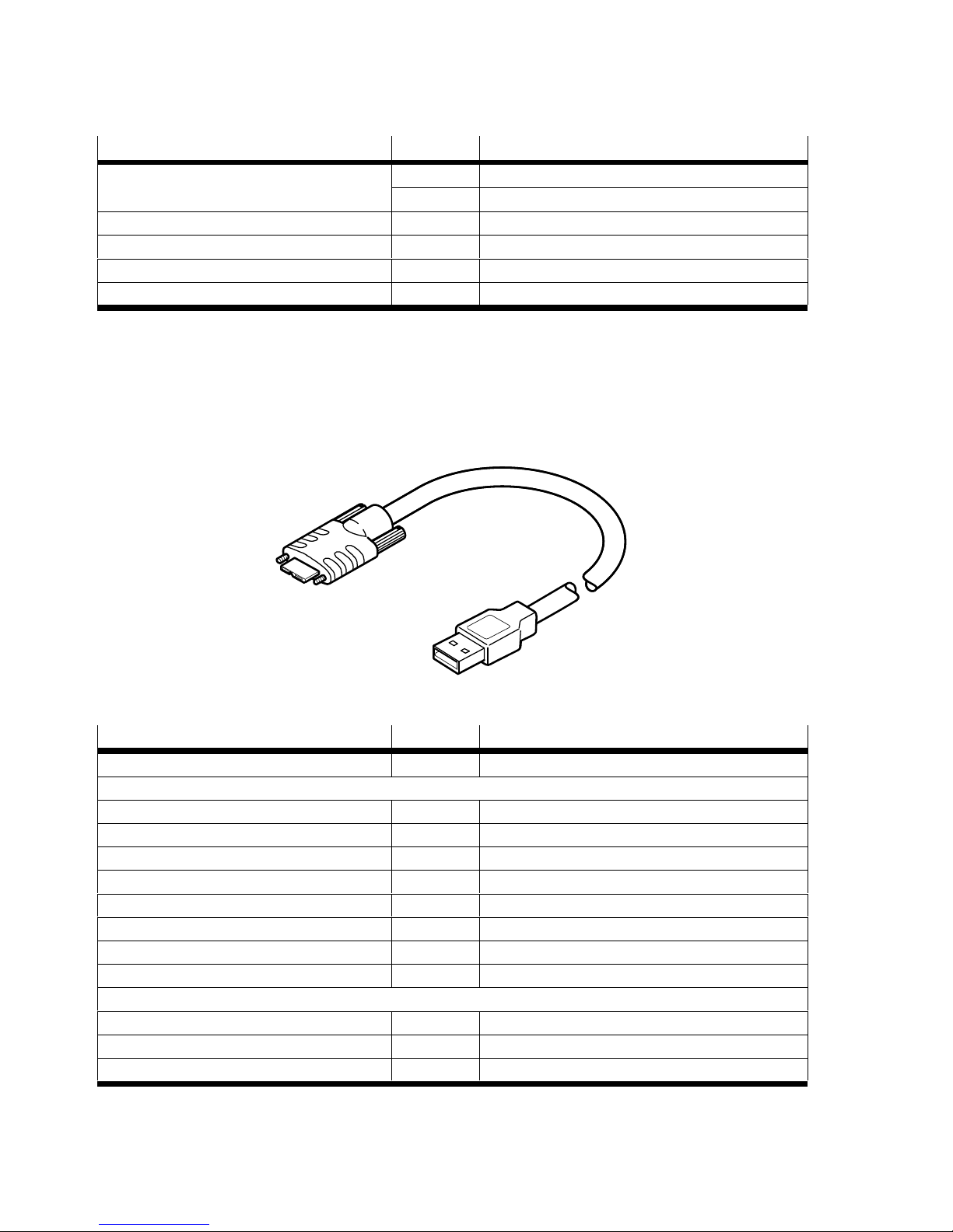
The NEBC connecting cable is a cable with 2 different connection sides (type A, type B 3.0 micro, each
USB compatible) for connecting the SBRD-Q controller to the SBPB camera heads.
Fig. 3.3 NEBC connecting cables
Feature Code Value
Connecting cables [NEBC] For controllers
Field device side
Connectors left side [U7] USB compatible, type B micro
Cable outlet, left [G] Straight
Number of pins/wires left [10] 10-pin
Cable characteristics [K] Standard
Cable design [S] With shielding
Cable length [5] 5 m
Cable designation [N] Without label holder
Type of connector [S] Plug connector on both sides
Controller side
Connectors right side [U5] USB compatible, type A
Cable outlet right [G] Straight
Number of pins/wires right side [9] 9-pin
Tab. 3.3 Order code
Page 15
3 System overview
Festo – SBRD-EN – 2017-11 – English 15
3.3 Software packages
The FFT software (Festo Field Device tool) and the CCS (Camera Configuration Studio) are used for com
missioning and operation.
Note
Minimum requirements that the PC must fulfil in connection with the software packages
are described in the Help of the respective software package.
The FFT software provides the following functions:
Subject
Function
Basic configuration
and commissioning
– Changing of the device's network settings (IP address, gateway,
password, etc.)
– Transmission of firmware to the controller
Tab. 3.4 Functions of the FFT software
The CCS software provides the following functions:
Subject Function
Configuration and
commissioning,
creating jobs
– Determination of the signal behaviour
– Determination of the cameras and camera characteristics
– Determination of the evalution and output functions
– Determination of tools and tool characteristics
Analysis – Display of evaluated parts, live images, statistics and handling of jobs
Diagnostics – Display of the device characteristics
– Display of errors
Service – Documentation of a system
Tab. 3.5 Functions of the CCS software
3.4 Accessories
Please select additional accessories from the catalogue è www.festo.com/catalogue.
Page 16
4 Assembly
16 Festo – SBRD-EN – 2017-11 – English
4 Assembly
Warning
Before undertaking mounting, installation or maintenance work, switch off
the operating voltage supply for the electronics.
Note
Uncontrolled external light influences generation of the images and thus the results.
Use screening (e.g. opaque black housing) against uncontrolled external light
(e.g. ceiling lights, windows, etc.).
Note
Handle lens of the camera carefully.
Avoid contamination. Work in a clean environment.
Do not touch the inside of the camera, lens elements or glass surfaces.
Note
Connect to the product only devices approved by Festo. In mixed operation, there is
the danger of electric destruction.
Note
Camera connection is sensitive to electrostatic discharges. These can result in image
disturbances during operation.
If an electrostatic discharge is possible: Do not touch the camera connection during
operation.
Page 17

4 Assembly
Festo – SBRD-EN – 2017-11 – English 17
4.1 Mounting of the camera system
4.1.1 Mounting of the SBRD-Q controller
The SBRD-Q controller can be mounted as follows:
On an H-rail
With 2 M4 screws in the fastening holes of the housing
Position the SBRD-Q controller so that the ventilation grille is arrayed horizontally. This ensures air flow
through the device from bottom to top as well as possible.
4.1.2 Mounting of SBPB camera head
There is a threaded hole pattern on the bottom of the SBPB camera head. Use only
the SBAMC11-CP mounting kit è Tab. 4.1.
Use only the screws and toothed discs provided. Always use toothed discs. Pay attention to thread
length.
Mount the camera head with the help of the adapter kit so that it is aligned on the inspection part
suitably and without obstacle è Tab. 4.1.
Observe that the distance between camera and inspection part is adapted to the optics.
In case of high ambient temperatures, mount the camera head on a cool surface.
A functional earth connection is present on the mounting plate of the SBAM camera. Connect this to
earth potential with low impedance.
4.1.3 Mounting of NEBC connecting cable
Plug the NEBC connection cable on the controller side into the connection X7 or X9.
Plug the NEBC connecting cable into the USB-compatible connection on the back of the camera and
secure it against loosening with the corresponding locking screws.
Ensure permanent strain relief on both sides.
Do not use narrow cable binders for mounting, as otherwise the internal structure of the cable can
be damaged.
Secure plug connector at SBRD-Q controller and at the SBPB camera head so it will not be accident
ally unplugged or loosened (e.g. through vibration).
Page 18
4 Assembly
18 Festo – SBRD-EN – 2017-11 – English
The following adapter kits are used for mounting the respective components:
Type
Designation Manual
SBAM-C11-CP Mounting Adapter kit for camera on dovetail mounting
SBOA-HMSV-39 Adapter kit Adapter kit for mounting with dovetail plate, which can be
screwed on (dovetail plate contained in the adapter kit)
SBOA-HMSV-40 Adapter kit Adapter kit for mounting to dovetail plate, e.g. HMSV-11 plate
(not included in the adapter kit)
SBOA-HMSV-41 Adapter kit Adapter kit for mounting with female thread ¼–20 UNC
for mounting to commercially available photo/video tripods
SBAM-C6-A2-AF Swivel mounting Swivelling and adjustable mounting for attachment of
the camera heads using dovetail system.
Tab. 4.1 Adapter kits for mounting
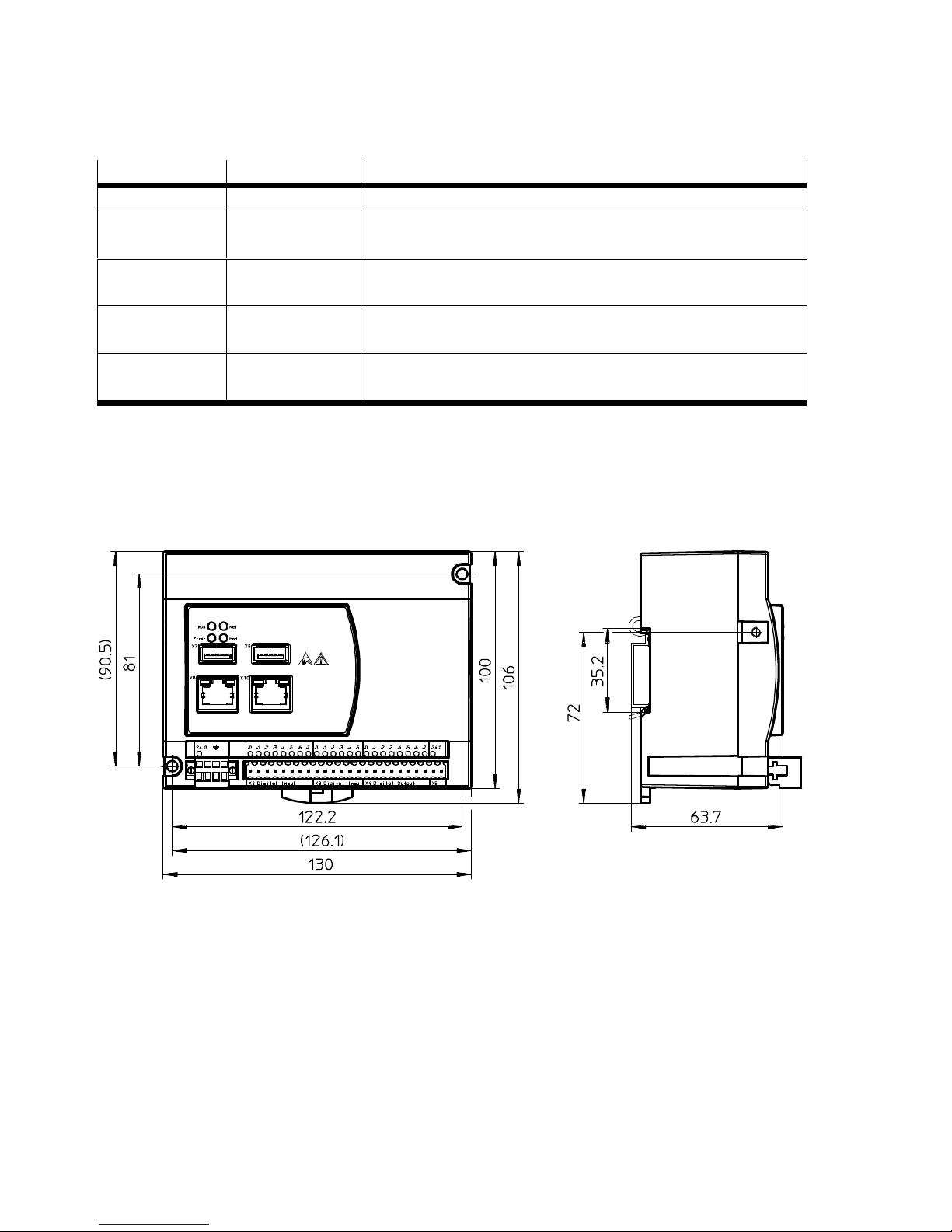
4.2 Dimensions of SBRD camera system
4.2.1 SBRD-Q controller
Fig. 4.1 Dimensions
Page 19
4 Assembly
Festo – SBRD-EN – 2017-11 – English 19
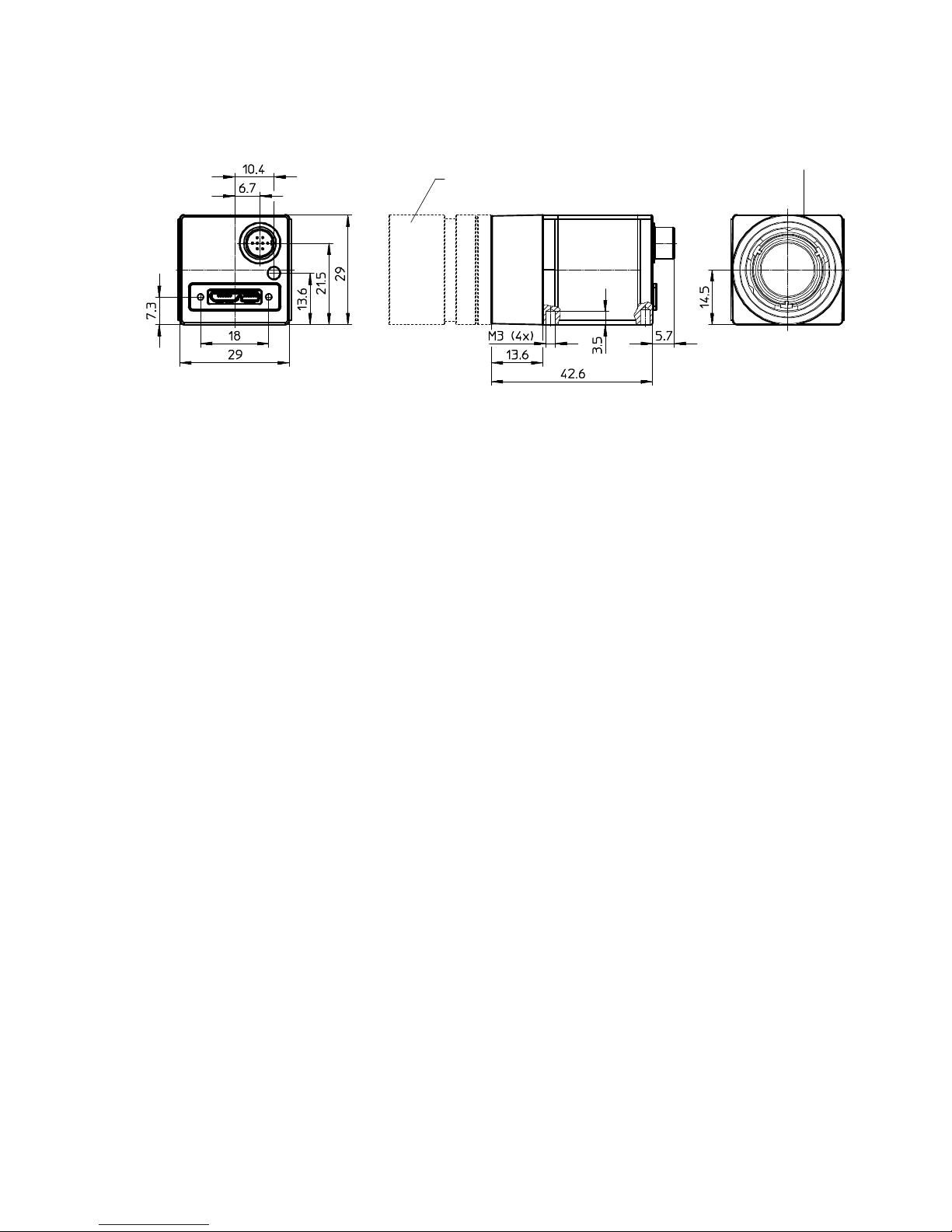
4.2.2 SBPB camera head
1 2
1 Lens not included in the scope of delivery
2 Optical axis
Fig. 4.2 Dimensions
Please use the Support Portal è www.festo.com/sp for further information about dimensions.
Page 20
5 Installation
20 Festo – SBRD-EN – 2017-11 – English
5 Installation
5.1 General installation instructions
Note
The product can generate high frequency malfunctions, which may make it necessary to
implement interference suppression measures in residential areas.
Caution
Malfunctions caused by electromagnetic factors.
– Connect the function unit connections with low impedance to the earth potential.
– Connect the H-rail with low impedance to the earth potential.
Note
Long signal lines reduce the resistance to interference.
Make sure that the cable lengths listed in the following table are complied with:
Cable type Permissible cable lengths
Signal lines Max. 30 m
NEBC connecting cable Max. 5 m
Ethernet > 30 m
Tab. 5.1 Maximum permissible cable lengths
Note
Emergency off:
In accordance with EN 60204-1: Electrical safety is ensured in case of emergency by
switching off the electrical energy to all or part of the installation. Emergency off is to
be used where a risk of electric shock or other electrical risk exists.
Page 21
5 Installation
Festo – SBRD-EN – 2017-11 – English 21
5.1.1 Selecting the power pack
Warning
For the electrical power supply, use only PELV circuits in accordance
with IEC/DIN 60204-1 (Protective Extra-Low Voltage, PELV).
Also observe the general requirements for PELV circuits in accordance
with IEC/DIN EN 60204-1.
Only use power sources which guarantee reliable electrical isolation of the operating
voltage in accordance with IEC/DIN EN 60204-1.
Protection against electric shock (protection against direct and indirect contact) is guaranteed in ac
cordance with IEC/DIN EN 60204-1 by using PELV circuits (Electrical equipment of machines, general
requirements).
Warning
Fire risk.
Injury from hot surfaces.
The product must be supplied from a single voltage source that meets
the requirements for energy-limited circuits or from an energy-limited voltage source
(LPS) or from a Class 2 circuit. Observe IEC 61010-1/EN 61010-1.
Simple 24 V transformers with rectifier and filter capacitor achieve output voltages of 28 V and more at
low load. Proper operation is guaranteed only if the permitted operating voltage range is not exceeded
è Technical data in Appendix A.1.
Page 22
5 Installation
22 Festo – SBRD-EN – 2017-11 – English
5.2 Electrical connections
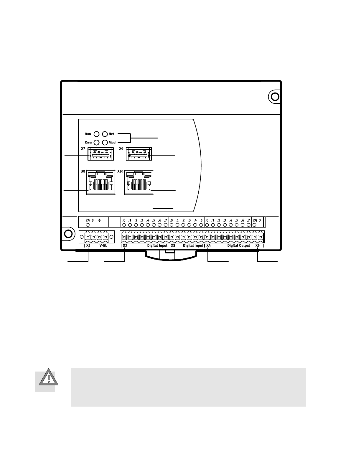
SBRD-Q controller
12
3
4
5
6
7
8
9
aJ
aA
1 X1 controller power supply
2 X2 digital inputs (with integrated pull-up)
X2.2, X2.3 related GND: X2.0, X2.1 digital
inputs X2.4 – X2.7
3 X3 digital inputs X3.0 – X3.5
4 X4 digital outputs X4.0 – X4.7
5 X5 power supply outputs
6 Status LEDs
7 X7 camera interface
8 X8 Ethernet interface
9 X9 camera interface
aJ X10 reserved
aA SD memory card module
Fig. 5.1 SBRD-Q controller
The following connection options are available: è Chapter 6.4 and Tab. 6.2.
5.2.1 Connection of the operating voltage supply and the I/Os
Caution
Damage to components.
Ensure compliance with the permissible operating voltage range
è Technical data, Chapter A.1.
The power supply is brought to the X1 port through the 4-pin plug labelled 24 V DC.
Page 23
5 Installation
Festo – SBRD-EN – 2017-11 – English 23
The following components are supplied with +24 V DC through this connection:
– Internal electronics of the camera system.
– Inputs.
The outputs X4 are supplied with +24 V DC through the 2-pin plug X5.
Warning
Malfunction due to electromagnetic interference.
Connect screening to the connection for functional earth FE.
Connect plug X1 with low impedance to the earth potential.
The function and functional behaviour of the I/O are configured with the CCS software and stored in
the respective job. The functional behaviour of the I/O must be differentiated in the various evaluation
modes è Chapter 6.3 ff.
Please observe the following:
– Comply with tolerance 24 V DC ± 10 %.
– Connect the FU connection of the X1 plug to earth potential with low impedance.
– Current must not exceed 450 mA per output.
– Connect cable screening to earth potential with low impedance.
– For inputs with integrated pull-up resistor (X2.0 and X2.1)
use shielded cables and attach shield on both sides to the earth potential
with low impedance. Maximum unshielded length 100 mm.
– Outputs and inputs are galvanically isolated:
– Outputs are supplied through X5, potential related to GND_IO.
– Inputs are supplied through X1, potential related to GND.
5.2.2 Connecting the Ethernet interface
Note
With an active connection to the systems in the network, large amounts of data can be
transmitted, depending on the mode of operation. This places a corresponding load on
the network between the PC and system. A direct connection is therefore preferable.
Ensure that corresponding band widths and an optimal network structure are
available.
Comply with necessary system requirements.
Page 24
5 Installation
24 Festo – SBRD-EN – 2017-11 – English
Note
Unauthorised access to the camera system can cause damage or malfunctions.
Protect network against unauthorised access.
Measures to protect the network include firewall, intrusion prevention system (IPS),
network segmentation, virtual LAN (VLAN), virtual private network (VPN),
security at physical access level (port security). For additional information
è Guidelines and standards for security in information technology, e.g. IEC 62443,
ISO/IEC 27001. An access password only protects against unintentional
modification.
For commissioning and configuration of the camera system, a connection with the PC must be made
via Ethernet.
For special requirements of permanent use in an industrial environment, use a Category 6 Ethernet
cable which fulfills requirements for oil-resistance, bending radius, permissible bending cycles,
etc. Connections: 2x RJ45 plug.
5.2.3 Connecting the camera
– Use only the cable and accessories approved by Festo è Tab. 3.3, Tab. 5.1.
– Do not install any further USB accessories (angle cable adapter, extension cable, hub, etc.)
between camera and controller.
Page 25

6 Commissioning
Festo – SBRD-EN – 2017-11 – English 25
6 Commissioning
6.1 Information on commissioning
Prior to commissioning, mounting and installation of the device should be completed.
Use the FFT software to change the network settings or firmware of the device.
Perform commissioning and configuration with the CCS software è Help for CCS.
The steps for commissioning normally take place in the sequence shown in the next chapter. For optim
isation of the system, it is sometimes necessary to repeat steps that have already been performed.
6.2 Firewall settings on the PC
When a firewall is used on the PC, the network traffic is allowed or prohibited using a define firewall set
of rules. This also affects communication of the software packages with the camera system.
After the installed software packages start, at the first attempt at communication between software
and camera system, a dialogue normally begins with information that this communication is blocked by
the firewall. The blockade can be permanently lifted in this dialogue. Manual approval of communica
tion can also be granted later in the firewall settings over the network.
Communication of the installed software packages with the camera system takes place through
socalled ports. Some firewalls permit network traffic through enabling of these ports.
Enable use of the following ports in the firewall:
Port Transmitting Purpose
2222 UDP EtherNet/IP (Multicast)
4386 TCP Firmware download, Add-in download and backup with PC software
9997
1)
TCP Telnet-XML
9998
1)
TCP Telnet-Streaming
9999
1)
TCP Telnet
10000 TCP Data exchange with PC software
10001 TCP Data exchange with PC software
10002 UDP Device search with PC software (Multicast)
44818 TCP EtherNet/IP
1) Standard setting of the camera system
Tab. 6.1 Ports to be enabled for software packages and fieldbus protocols
Page 26
6 Commissioning
26 Festo – SBRD-EN – 2017-11 – English
6.3 Selection of the evaluation mode
The evaluation mode determines when a picture of an inspection part is taken, processed and checked
and the results are output.
Note
Selection of the evaluation mode determines how the device reacts to input signals or
when the inspection results can be sent to the outputs. Here, observe the descriptions
of the signal processes starting with Chapter 6.3.1 ff.
The following evaluation modes can be selected through the Evaluation mode job parameter in the CCS
software è Setting in Job Navigator step 1. Set up in the job parameter window, evaluation section:
– Triggered: single frame shooting and inspection with each valid trigger signal
– Free wheel unit: continuous image recording and inspection (no fixed frame rate) as long as the trig
ger signal is present
Selection of the evaluation mode is dependent on the respective application, in particular the following
factors:
– Inspection part rate and inspection part flow
– Inspection part (component part or continuous part)
– Interaction with a higher-order controller
Use and operation of the modes
Triggered
Inspection of component parts in stop-and-go or slow parts flow. The trigger signal is triggered through
a higher-order controller or a sensor, for example, as soon as the inspection part is in the field of view
of the cameras. The inspection results are output after completion of the inspection, then the device
waits for the next valid trigger signal.
Free wheel unit
Inspection of component or continuous parts at medium to fast (continuous) parts flow.
The trigger signal is present continuously, regardless of whether an inspection part is located in front of
the camera system. The device acts similarly to a simple sensor. The inspection results are output after
completion of the test. Then the device starts immediately with the next inspection.
Hinweis
All SBPB camera heads connected to the SBRD-Q controller and configured in the current job are star
ted through a common trigger signal. Possible trigger signals are:
– A digital input at X2 or X3 è Electrical connections 5.2 (configurable through the CCS software
è Job Navigator, step 6, Configure I/O, selection Digital inputs).
– Trigger function in the CSS software.
– Protocol-based I/O (e.g. via Telnet).
An inspection is considered completed when all calculations configured in the current job have been
performed. That is, inspection results from images of individual camera heads are not output individu
ally, but only when the overall inspection result of the current job is available.
Page 27
6 Commissioning
Festo – SBRD-EN – 2017-11 – English 27
6.3.1 I/O process with triggered evaluation mode
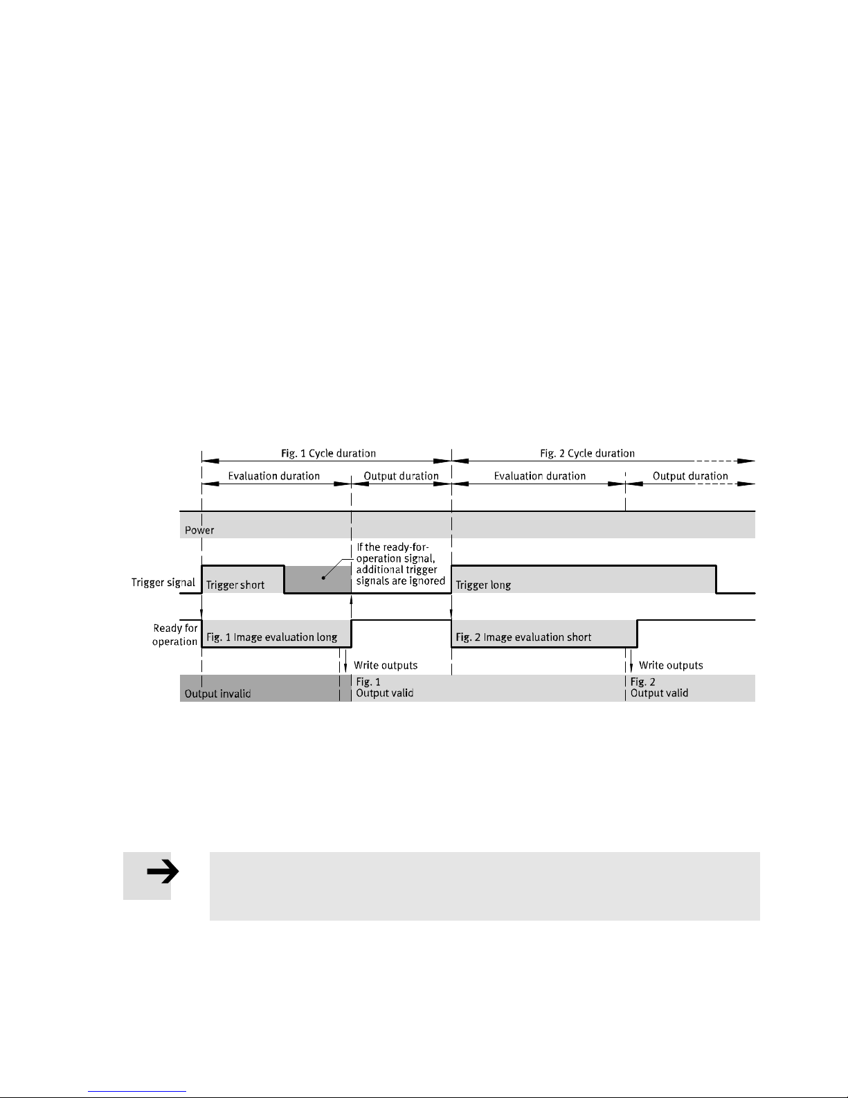
In the triggered evaluation mode, exactly one cycle (edge-controlled) is started through a valid signal at
the trigger signal input. A cycle contains the image evaluation and output of the results.
Trigger signals are valid only under the following conditions:
– Ready for operation output signals logic 1
Image evaluation begins with the trigger signal. During image evaluation, the ready for operation
output signals logic 0.
The results are sent to the outputs no earlier than upon completion of the image evaluation.
The ready for operation output is set for logic 1 only when the results are validly present at all outputs.
The results can now be processed by a higher-order controller (PLC/IPC), for example.
These results remain at the outputs until the next trigger signal.
Signal process with standard settings
The signal process with standard settings of the job parameters in the triggered evaluation mode could
appear as follows.
Fig. 6.1 Triggered evaluation mode – signal process with standard value settings
Function and behaviour of the inputs and outputs are determined at configuration of the job with
the CCS software è Chap. 6.4.
Acceptance of the I/O signals by a higher-order controller can be accomplished with the rising edge of
the ready for operation signal è Fig. 6.1.
Note
Simplified representation of the signal processes. These contain no jitter, run times or
system-related delays.
Page 28
6 Commissioning
28 Festo – SBRD-EN – 2017-11 – English
6.3.2 I/O process with free wheel unit evaluation mode
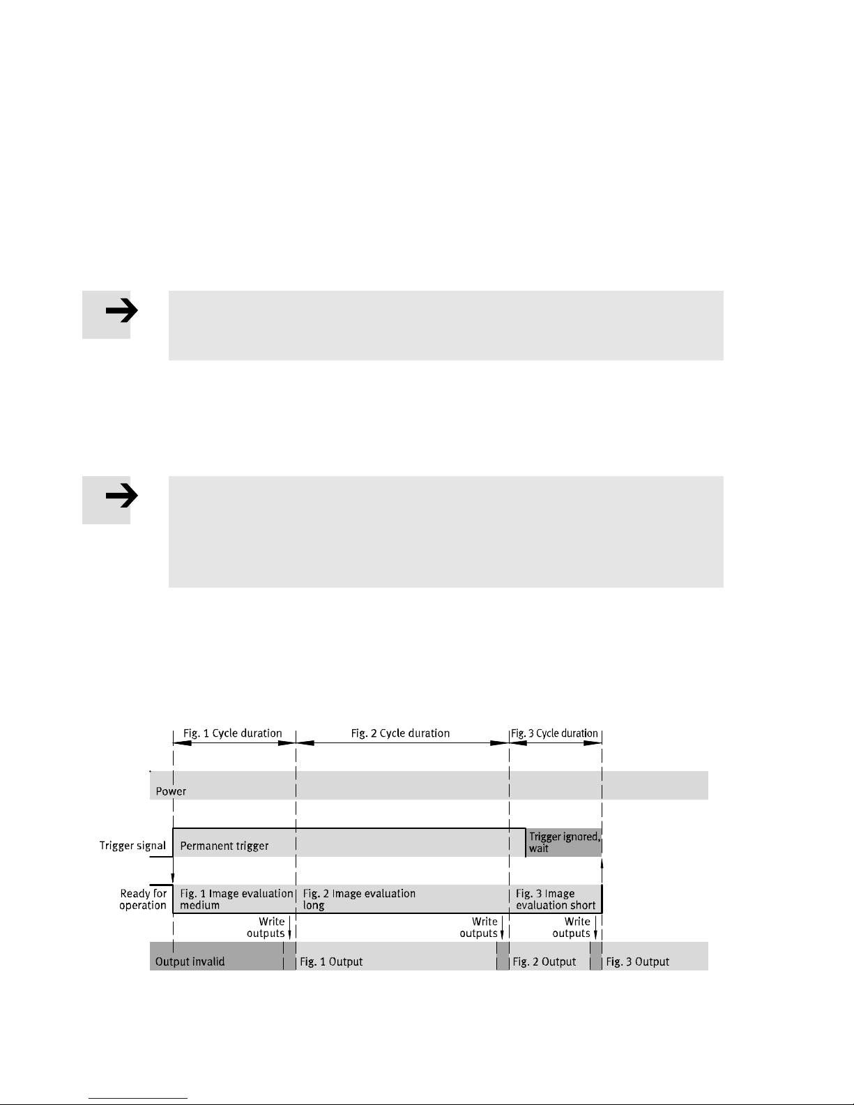
In the free wheel unit evaluation mode, the free wheel mode remains active as long as logic 1 is present
at the trigger signal input (status-controlled). During this time, images are generated and evaluated
cyclically.
Image evaluation begins with the start of the cycle. During image evaluation, the ready for operation
output signals logic 0. Between two cycles, the ready for operation output can send a logic 1
è Fig. 6.2.
Note
The rate at which images are recorded or results are output varies and depends on
the evaluation duration of the individual images.
Function
In this evaluation mode, the device acts similarly to a simple sensor that inspects and outputs
continuously. As a result, a continuous evaluation can be achieved. But synchronisation of the outputs
with a higher-order controller (PLC) is only conditionally possible.
Note
The results are written to the outputs only when the device is finished with image
evaluation.
The outputs remain valid until the next image evaluation cycle has been worked
through.
If the trigger signal input is reset to logic 0, the free wheel unit is ended. After the current image evalu
ation is completed, the ready for operation output signals logic 1 again è Fig. 6.2.
Signal process with standard settings
The signal process with standard settings of the job parameters in the free wheel unit evaluation mode
could appear as follows:
Fig. 6.2 Free wheel unit evaluation mode - signal process with standard settings
Page 29
6 Commissioning
Festo – SBRD-EN – 2017-11 – English 29
Function and behaviour of the inputs and outputs are determined at configuration of the job with
the CCS software è Chap. 6.4.
Acceptance of the I/O signals by a higher-order controller can be accomplished with the rising edge of
the ready for operation signal.
Note
Simplified representation of the signal processes. These contain no jitter, run times or
system-related delays.
Page 30
6 Commissioning
30 Festo – SBRD-EN – 2017-11 – English
6.4 Connection to higher-order controller
For control of the device or processing of the inspection results, a higher-order controller (PLC) can be
connected to the camera system through the available connection options.
The following I/O functions are available, depending on the device and firmware used. Assignment to
a connection or interface is done during configuration of the job:
Connection Input functions Output functions
Device internal, digital I/O
module at the plugs X2, X3,
X4
– Trigger signal
– Acknowledge error
– Acknowledge error, apply
input signal
– Job number
– Apply input signal
– Not assigned
– Ready to operate
– Errors
– Pass on the input X2.2
– Pass on the input X2.3
– Always off
– Always on
– Configuration mode
– Inspection result OK
– Inspection result not OK
– Orientation correct
– Orientation incorrect
– Type
Communication over
Ethernet interface
(protocol-based I/O)
– Trigger signal
– Apply input signal
– Acknowledge signal error
– Job preselection
– Job parameter
– Job tolerances
– Ready to operate
– Warning and error status
– Detailed inspection results
with recognised parts type and
characteristics as values or
text
Tab. 6.2 Connection options of the camera system
Note
A higher-order controller must be programmed according to the signal behaviour of
the selected evaluation mode. Here, observe the descriptions of the signal processes
starting with Chapter 6.3.1 ff.
Logical status of inputs/outputs
Some I/O signals can be configured with the CCS software è Job Navigator step 6 Configure I/O, selec
tion Digital inputs or Digital outputs.
Page 31
6 Commissioning
Festo – SBRD-EN – 2017-11 – English 31
Note the difference between the electrical level (high-active, low-active) and the logic status (logic 1,
logic 0) of an input or output.
All signals are high-active in the factory settings and can be inverted in their logic in the CCS software.
Then they become low-active signals. All timing diagrams and representations assume this high-active
default setting. Inversion of the signals should only be made in exceptional cases by experienced users.
6.4.1 General information on use of inputs
There are inputs with signal function and other inputs.
Inputs with signal function
These inputs are edge- or status-controlled, depending on the evaluation mode. They are read con
stantly. If the signals are valid with regard to the current operating status, the corresponding action is
carried out immediately. Inputs with signal function include:
– Trigger signal
– Acknowledge error
– Acknowledge error, apply input signal
– Apply input signal
Other inputs
These inputs are status-controlled, that is, they react to logic 1 or logic 0.
Example for normal input: job preselection
Note
The inputs can be read through the Telnet communication protocols and in the job,
independently of the selected function.
Function assignment
Connections and interfaces of the SBRD-Q controller can be equipped with almost any assignment of
functions. Configuration is made through the CCS (Camera Configuration Studio) software
è In Job Navigator step 6 Configure I/O, selection Digital inputs or Digital outputs. The configuration
is stored in the respective job.
Note
The input statuses are read during processing of the job after the image is recorded.
But the time when they are read in during image processing is not determined exactly,
so changes to the input statuses during evaluation can lead to unforeseen results.
Make sure that no changes are made to the input statuses during evaluation.
Page 32
6 Commissioning
32 Festo – SBRD-EN – 2017-11 – English
Trigger signal input
The input with the assigned trigger signal function starts and stops the inspection process. The mode of
operation, signal detection and signal process are dependent on the selected evaluation mode
è Chapter 6.3.1 ff.
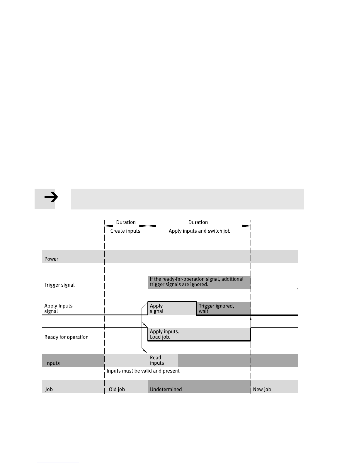
Apply signal inputs input
The input with the assigned apply signal inputs function loads a new job. The number of the new job
must previously be specified through the I/O options. Apply signal inputs is edge-controlled detected
and accepted only as long as a logic 1 is present at the ready for operation output.
To read inputs again (load job), the apply signal inputs must at first be reset due to edge detection.
As long as the inputs are read and the job is loaded, the ready for operation output sends a logic 0.
During this time, no parts can be inspected. The trigger signal is not valid as long as the ready for opera
tion output sends logic 0.
As soon as the job has been loaded, the ready for operation output signals logic 1 again. Trigger signals
for an inspection are now accepted.
Note
When a job has been loaded, the inspection results and the related flag words are reset.
Fig. 6.3 Signal process: apply inputs – switch job
Page 33
6 Commissioning
Festo – SBRD-EN – 2017-11 – English 33
Note
Simplified representation. The signal processes contain no jitter, run times or systemrelated delays.
Note
The inputs must be validly present for a certain time, depending on the I/O options
used.
Acknowledge error signal input
If an error state occurs, this is displayed at the error status output with a logic 1. In addition, the ready
for operation output goes to logic 0.
Incoming trigger signals are not valid, that is, no further evaluations are possible until the error is elim
inated.
The error must be eliminated through suitable means, while the system remains in an error status.
Diagnostics and changing of job parameters are still possible.
Use the CSS software or all protocols that can access job parameters.
As soon as the error has been eliminated, this must be reported to the camera system through
the input with the related acknowledge signal error function. The acknowledge error signal is edgecontrolled detected.
Information on the errors (description and recommendations for elimination) is in Chapter 7.1.2.
6.4.2 Use of the Ethernet interface with Telnet
The device provides the Telnet protocol for communication with a higher-order controller, robot, or PC.
This allows very comprehensive output and control options. Inspection results can be processed fur
ther in the higher-order controller, for example, to grasp a part with a robot.
Support of the Telnet function by the camera system must be activated through job parameters. Read
ing and writing are performed through a text-based command line with defined commands, where
the data to be read/written are defined by memory addresses.
Besides simple commands for image recording, among other things, the device also makes available
access to the results of an inspection and the settings of the job parameters.
Specific memory addresses can be read and written, while some can only be read or written
è Tables in the appendix A.3.
Page 34
6 Commissioning
34 Festo – SBRD-EN – 2017-11 – English
Commissioning:
1. Switch off system to avoid errors or damage. Disconnect power supply to the camera system and to
the device to be coupled.
2. Connect the camera system through specified cables to the device to be coupled, e.g. through an
Ethernet switch or hub.
3. Connect power supply again.
4. Create a connection to the camera system with CCS software and set the job parameters under
the Telnet function:
– The TCP port job parameter determines which port should be used for Telnet communication.
– The Telnet server job parameter activates the Telnet function and also established additional pro
tocol characteristics:
– On (normal function): The device to be coupled does not use the Telnet S7 module end.
– On (S7 module end): When the Telnet S7 module end is used on a corresponding controller.
5. In the device to be coupled, set IP address and the used Telnet port of the camera system.
6. Program the device to be coupled in order to access data of the camera system.
Note
Contact Festo Service if the S7 module end is used. General information on inputs is
found in Chapter 6.4.1. The available memory addresses and functions are located
in the appendix A.3.
Test of the Telnet communication
Most PC operating systems have a Telnet program on the command line level. The Telnet connection to
the camera system can be tested with this program.
Page 35
6 Commissioning
Festo – SBRD-EN – 2017-11 – English 35
Windows operating system
Requirements in the Windows operating system
Activate the Telnet Client option in Windows system control. è Help function in the Windows oper
ating system.
Open window through the Windows start menu. è Help function in the Windows operating system.
Start Telnet program and transfer the IP address of the camera system as well as the port number
established in the TCP port job parameter.
Calling up Telnet program
telnet 192.168.4.2 9999
This builds up a connection to the camera system.
Telnet program with feedback SBRD-Q:
20 SBRD-Q: no authentication required.
Note
If the entries in the Telnet are not visible, the so-called “Local Echo” must be activated
in the Telnet. Information on this can be found in the Telnet program help.
Note
The Telnet function of the camera system supports up to 10 active connections.
This permits fast reconnection if a connection is interrupted.
If an attempt is made to build up more than 10 connections, the following error message results:
–6 ERROR: maximum number of connections reached
After this message, the connection is ended.
Page 36

6 Commissioning
36 Festo – SBRD-EN – 2017-11 – English
6.4.3 Telnet commands
WFW – Write Flagword
WFW <address, value>
Writes a value to the specified flag word address è Appendix A.3.
The following example writes the value 600 to the flag word address 1000 (exposure time of the first
camera in microseconds).
Write to a flag word address:
WFW 1000, 600
1 OK: operation successful.
In case of error, a response is made with an error code and an error message.
Note
Changes to values and settings using WFW are not stored remanently but only until
a job change or disconnection of the power supply. If the settings are to be stored
remanently, the STORPRG command must also be used.
RFW – Read FlagWord
RFW <address>
Outputs the current value of the specified flag word address as text è Appendix A.3.
Up to 64 addresses can be read out with this command. To achieve this, the flag word addresses must
be specified separated by commas:
RFW <address1, address2, address3, …>
Reading out flag word addresses:
RFW 153, 154, 155
10, 42, 17
RNV – Read Named Value
RNV [name of the characteristic]
Outputs the current characteristic value of the specified characteristic è Appendix A.3.
Up to 64 characteristic values can be read out with this command. The characteristic names must be
specified between square brackets or quotation marks and separated by commas:
RNV [name 1], [name 2], [name 3], …
Page 37
6 Commissioning
Festo – SBRD-EN – 2017-11 – English 37
Note
The values are output only when the characteristic names are written completely and
correctly.
Use none of the following characters in the characteristic names when configuring
the job:
– Square brackets [ ]
– Quotation marks “ ”
– Umlauts
– Special characters
Pay attention to capital and small letters in the characteristic names.
If no agreement is found, the device issues the following message:
–55 ERROR: one or more feature name(s) not valid
The characteristic values can only be requested with this command if their output was previously con
figured in the CCS software in the selected job with the help of the protocol-based I/O result flag word
è Job Navigator, step 6, Configure I/O, selection result flag words.
The characteristic names are stored in the job and can be determined when the job is created
(in CSS software).
Preferably use meaningful characteristic names.
Note
If several characteristic names are identical, the value of the first characteristic whose
name matches is output.
RDO – Read Data Output
RDO [name of the protocol-based I/O]
Outputs the values of the corresponding protocol-based I/O.
Page 38

6 Commissioning
38 Festo – SBRD-EN – 2017-11 – English
Note
Protocol-based I/Os can only be requested if they were previously stored in the CCS
software CCS in the selected job with the corresponding name.
An error message appears if no protocol-based I/Os were created.
Details on configuration of protocol-based I/Os are located in the online help of the CCS
software.
The values are output only if the name of the protocol-based I/O was written completely
and correctly.
Use none of the following characters for names of the protocol-based I/Os when
configuring the job in the CSS:
– Square brackets [ ]
– Quotation marks “ ”
– Umlauts
– Special characters
Pay attention to capital and small letters.
If the protocol-based I/Os exist and use the Telnet protocol, the result depends on the output format:
– Telnet – Part Detector: binary coded
– Telnet – Data Collection: binary coded
– Telnet – XML: XML coded
Note
The structure and contents of the protocol-based I/Os are displayed in CCS
in the results window of the respective I/O. As a result, programming of the controller
for acceptance of the data can be implemented easily
IMAGE
Image evaluation
This IMAGE command is allowed only in the evaluation mode triggered and free wheel unit. The com
mand performs a complete evaluation. The inspection results and characteristics are entered at
the corresponding flag word addresses.
CHANGEPRG
CHANGEPRG job number
The job can be changed with this command. The values 1 to 255 are allowed as job number.
Requirements:
– The device is not in the configuration mode. If the device is in the configuration mode, only the new
job number is stored without changing into the job. If the configuration mode is ended, the device
changes into the job with this job number.
– The device is ready for operation:
ready for operation output signals operational readiness.
Page 39

6 Commissioning
Festo – SBRD-EN – 2017-11 – English 39
STOREPRG
STOREPRG job number
With this command, the current job with its settings can be stored remanently under the job number.
All parameter settings that were changed using WFW, for example, are first stored permanently on
the device with the STOREPRG command.
EXIT
End connection
The camera system closes the Telnet connection.
VERSION
Sensing of the version of the Telnet server and of the version of the device.
6.4.4 Messages and error descriptions
Code
Message/error Description
20 SBRD-Q No authentication
required
– Initial message of the server after
the connection is established if
no authentication is required
1OK Operation successful – Command was successfully executed.
–1 ERROR Parse error, or command
unknown
– Command is invalid.
– Error in the instruction
–5 ERROR Another client is already
connected
– Message if connection already exists
–6 ERROR Maximum number of
connections reached
– Message with attempts to build up more
than 10 connections
–10 ERROR Camera not ready – Camera system is not ready for operation
when the command is executed.
–11 ERROR Timeout during last
operation
– Allowed time exceeded during execution
of the command
–12 ERROR Response line overflow – The response command line exceeds
the valid number of characters.
–20 ERROR Program switch failed – Job could not be switched over.
–21 ERROR Program number not valid – Specified job number is not valid.
–30 ERROR Read offset not valid – One or more of the specified flag word
addresses for read access is invalid.
–40 ERROR Write offset not valid – Specified flag word address for write
access is invalid.
–42 ERROR Data type not valid – Used data type is invalid.
–50 ERROR String offset not valid – String address invalid.
–55 ERROR One or more feature
name(s) not valid
– One or more name(s) in the RNV (read
name value) command are invalid.
–56 ERROR Read data output – (-Other-) Error in protocol-based I/Os
Page 40
6 Commissioning
40 Festo – SBRD-EN – 2017-11 – English
Code DescriptionMessage/error
–58 ERROR Read data output: name
not defined
– Protocol-based I/Os are not set up
for specified names.
–59 ERROR Read data output: data
output not compatible
– Protocol-based I/Os not suitable for
output through Telnet or to the CoDeSys
module end.
–61 ERROR No authentication
required
– No authentication required (after use of
the control commands USER or PASS)
–62 ERROR Already authenticated – Connection is already authenticated
(after new use of the control commands
USER or PASS).
–63 ERROR No user provided – The command PASS was received before
transmission of a user name.
–200 ERROR Unspecified error – Error not described more closely.
Tab. 6.3 Messages and error descriptions
6.4.5 Use of the Ethernet interface with Telnet streaming
The device provides the Telnet protocol for streaming for communication with a higher-order controller,
robot, or PC. This allows very comprehensive output and control options. Inspection results can be
processed further in the higher-order controller, for example, to have a robot grasp a workpiece.
Note
Support of the Telnet streaming function by the camera system must be activated
through job parameters è CSS software.
The Telnet streaming function outputs data without explicit request to the configured TCP channel.
Up to 10 clients can receive the data.
On the Telnet streaming channel, data are output only under the following conditions:
– Telnet streaming function is activated.
– Selected job includes Telnet protocol-based I/O.
– Telnet protocol-based I/Os are configured for automatic output (streaming).
Note
With the CCS software, protocol-based I/Os can be added to a job and configured.
Page 41
6 Commissioning
Festo – SBRD-EN – 2017-11 – English 41
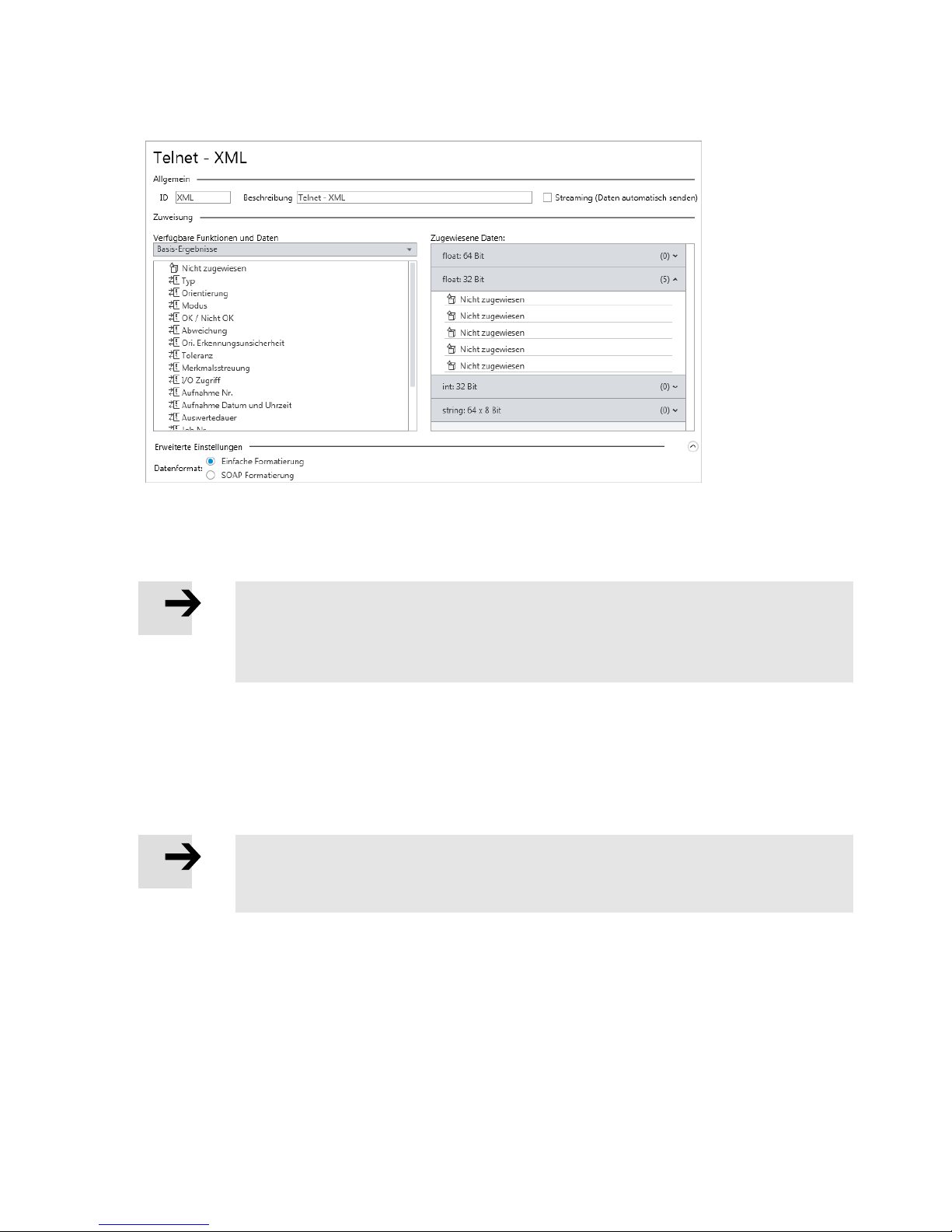
Fig. 6.4 Configure protocol-based I/O with Telnet streaming
Besides the data to be output, protocol-based I/Os establish their formats as well (binary, XML).
Additional information for creation of jobs can be found in the help for the CCS software.
Note
On the Telnet streaming channel
– No commands of clients are evaluated
– No error messages are output
6.4.6 Use of the Ethernet interface with Telnet XML
The device provides the Telnet protocol for XML for communication with a higher-order controller,
robot, or PC. This allows very comprehensive output and control options.
Inspection results can be processed further in the higher-order controller, for example, to have a robot
grasp a workpiece.
Note
Support of the Telnet XML function by the camera system must be activated through job
parameters è CCS.
Reading and writing are performed through a text-based command line with defined commands, where
the data to be read/written are defined by memory addresses.
Besides simple commands for image recording, among other things, the device also makes available
access to the results of an inspection and the settings of the job parameters.
Specific memory addresses can be read and written, while some can only be read or written
è Tables in the Appendix A.3.
Page 42

6 Commissioning
42 Festo – SBRD-EN – 2017-11 – English
Commissioning
1. Switch off system to avoid errors or damage. Disconnect power supply to the camera system and to
the device to be coupled.
2. Connect specified cables of the camera system to the device to be coupled, e.g. through
an Ethernet switch or hub.
3. Connect power supply again.
4. Create a connection to the camera system with the CCS software and set the job parameters under
the Telnet function:
– The XML TCP port job parameter determines which port should be used for Telnet communication
with XML.
– The XML Telnet server job parameter activates the Telnet function with XML.
5. In the device to be coupled, set the IP address and the used XML Telnet port of the camera system.
6. To access data of the camera system: Program the device to be coupled.
Note
General information on inputs is found in Chapter 6.4.1. The available memory
addresses and related functions are located in the Appendix A.3.
Test of the Telnet communication
Most PC operating systems have a Telnet program on the command line level. The Telnet connection to
the camera system can be tested with this program.
Requirements in the Windows operating system
Activate the Telnet Client option in Windows system control. è Help functions in the Windows
operating system.
Open window through the Windows start menu è Help function in the Windows operating system.
Start Telnet program and transfer the IP address of the camera system as well as the port number
established in the XML TCP port job parameter.
Start of the Telnet program through the command line:
telnet 192.168.4.2 9997
This builds up a connection to the camera system.
Telnet program with feedback SBRD-Q:
<Camera>
<CommandResultCode>20</CommandResultCode>
<CommandResultText>SBRD-Q: no authentication required.</Com
mandResultText>
</Camera>
Note
The inputs in the Telnet might possibly not be visible. Activate the so-called Local Echo
in the Telnet. Corresponding information can be found in the Telnet program help.
Page 43
6 Commissioning
Festo – SBRD-EN – 2017-11 – English 43
XML structure
The return values of the camera system in the XML format always follow this syntax:
– There is exactly one root element with the name
<Camera>…<Camera>
– Success and error messages consist of an integer code and an explanatory text in the following
form
:
<CommandResultCode>INTEGER</CommandResultCode>
<CommandResultText>STRING</CommandResultText>
Command Return value in case of success
Read FlagWord <DataResult_RFW>RESULT_VALUE</DataResult_RFW>
Read Named Value <DataResult_RNV>RESULT_VALUE</DataResult_RNV>
Read Data Output <DataResult_RDO>
/* User-defined – Begin */
<Name of the protocol-based I/O>
<float32_1>RESULT</float32_1>
<float32_2>RESULT</float32_2>
</Name of the protocol-based I/O>
/* User-defined – End */
</DataResult_RDO>
Detailed information on the individual commands are found in the section Telnet-XML commands.
Example
RNV “Angle of the edge”
<Camera>
<DataResult_RNV>108.949</DataResult_RNV>
</Camera>
Note
The Telnet function for XML of the camera system supports up to 10 active connections.
The attempt to build up more than 10 connections with the camera system results
in the following message:
<Camera>
<CommandResultCode>–6</CommandResultCode>
<CommandResultText>ERROR: maximum number of connections
Reached
</CommandResultText>
</Camera>
After this message, the connection is ended.
Page 44
6 Commissioning
44 Festo – SBRD-EN – 2017-11 – English
Telnet XML commands
WFW – Write FlagWord
WFW <address, value>
Writes a value to the specified flag word address è Appendix A.3.
The following example writes the value 600 to the flag word address 1000 (exposure time of the first
camera in microseconds).
Write to a flag word address:
WFW 1000, 600
In case of success, the OK message appears in the form:
<Camera>
<CommandResultCode>1</CommandResultCode>
<CommandResultText>OK: operation successful.</CommandResultText>
</Camera>
Note
Changes to values and settings using WFW are not stored remanently but only until
a job change or disconnection of the power supply. If the settings are to be stored
remanently, the STORPRG command must also be used.
RFW – Read FlagWord
RFW <address>
Outputs the current value of the specified flag word address as text è Appendix A.3.
Note
With the Telnet XML function, only 1 address can be read out.
Read out the flag word address
RFW 153
<Camera>
<DataResult_RFW>10</DataResult_RFW>
</Camera>
Page 45
6 Commissioning
Festo – SBRD-EN – 2017-11 – English 45
RNV – Read Named Value
RNV [name of the characteristic]
Outputs the current characteristic value of the specified characteristic name è Appendix A.3.
Note
With the Telnet XML function, only 1 characteristic value can be read out.
Note
A value is output only if the characteristic name was written completely and correctly:
Use none of the following characters in the characteristic name:
– Square brackets [ ]
– Quotation marks “ ”
– Umlauts
– Special characters
Pay attention to capital and small letters in the characteristic name.
In case of success, the result appears in the following form:
<Camera>
<DataResult_RNV>RESULT_VALUE</DataResult_RNV>
</Camera>
If no agreement is found, the device issues the following message:
<Camera>
<CommandResultCode>-55</CommandResultCode>
<CommandResultText>ERROR: one or more feature name(s) not valid.
</CommandResultText>
</Camera>
The characteristic names are stored in the job and can be determined when the job is created
(in the CSS software). The characteristic values can only be requested with this command if they were
previously configured in the CCS software in the selected job for output of result flag words
è Job Navigator, step 6, Configure I/O, selection result flag words.
Preferably use meaningful brand names.
Note
If several characteristic names are identical, the value of the first characteristic whose
name matches is output.
Page 46

6 Commissioning
46 Festo – SBRD-EN – 2017-11 – English
RDO – Read Data Output
RDO [name of the protocol-based I/O]
Outputs the values of the corresponding protocol-based I/O.
Note
Protocol-based I/Os can only be requested if they were previously stored in the CCS
software with the corresponding name.
An error message appears if no protocol-based I/Os were created.
Details on configuration of protocol-based I/Os are located in the online help of the CCS
software.
The values are output only if the name of the protocol-based I/O was written completely
and correctly.
Use none of the following characters for the name of the protocol-based I/O when
configuring the job in CSS:
– Square brackets [ ]
– Quotation marks “ ”
– Umlauts
– Special characters
Pay attention to capital and small letters
If the protocol-based I/Os exist and use the Telnet protocol, the result appears in the following form:
<Camera>
<DataResult_RDO>
<Name of the protocol-based I/O>
<float32_1>RESULT_VALUE_1</float32_1>
<float32_2>RESULT_VALUE_2</float32_2>
<string_1>RESULT_VALUE_N</string_1>
</Name of the protocol-based I/O>
</DataResult_RDO>
</Camera>
IMAGE
Image evaluation
The IMAGE command is allowed only in the evaluation modes triggered and free wheel unit.
The command performs a complete evaluation. The inspection results and characteristics are entered
at the corresponding flag word addresses.
Page 47
6 Commissioning
Festo – SBRD-EN – 2017-11 – English 47
CHANGEPRG
CHANGEPRG [job number]
The job can be changed with this command. The values 1 to 255 are allowed as job number.
Requirements:
– The device is not in the configuration mode. If the device is in the configuration mode, only the new
job number is stored without changing into the job. If the configuration mode is ended, the device
changes into the job with this job number.
– The device is ready for operation:
ready for operation output signals operational readiness.
STOREPRG
STOREPRG [job number]
With this command, the current job with its settings can be stored remanently under the job number.
All parameter settings that were changed using WFW, for example, are first stored permanently on
the device with the STOREPRG command.
EXIT
The connection is terminated with this command.
The camera system closes the Telnet XML connection.
VERSION
Sensing of the version of the Telnet XML server and of the version of the device.
Note
Messages and error messages è Tab. 6.3.
6.5 Notes for operation
Caution
Make sure that the systems connected to the camera system do not create any hazards.
Exceeding the permitted temperature range is detected through the internal electronics and results
in an error status.
Caution
A further temperature rise above this point can result in uncontrolled malfunctions.
Comply with permissible temperature range è Technical data A.1.
Page 48
7 Diagnostics and error handling
48 Festo – SBRD-EN – 2017-11 – English
7 Diagnostics and error handling
7.1 General diagnostics options
The following options are available for diagnostics:
– CCS software can show operating statuses and error messages of the camera systems used
è Help for CCS.
– Run LED, Error LED, Net LED, Mod LED, Speed LEDs and Link/Traffic LEDs on the connection side of
the SBRD-Q controller (è Fig. 5.1) provide the information listed in the following section:
7.1.1 Status indication
Optical display of the operating statuses is through status LEDs.
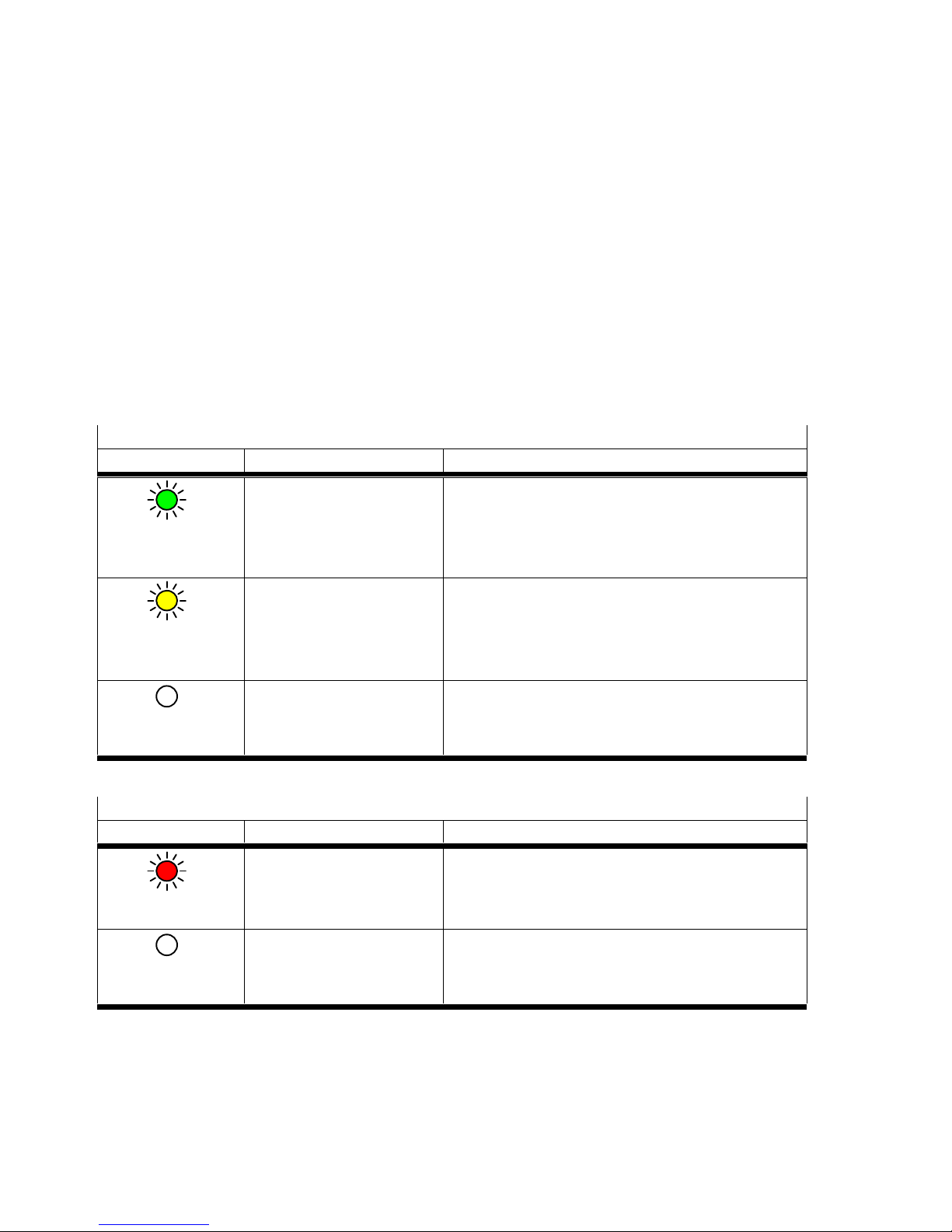
Run LED
LED Status Significance/error handling
LED illuminates
green
Device is ready for
operation.
–
LED illuminated
yellow
Commissioning is running.
Job shifting is running.
Wait until commissioning or job switching is
completed.
LED is off
Uncertain status, e.g.
operating voltage is not
applied.
Check power supply of the electronics.
Tab. 7.1 Run LED
Error LED
LED Status Significance/error handling
LED illuminated red
Errors –
LED is off
No error –
Tab. 7.2 Error LED
Net LED
Reserved
Mod LED
Reserved
Page 49
7 Diagnostics and error handling
Festo – SBRD-EN – 2017-11 – English 49
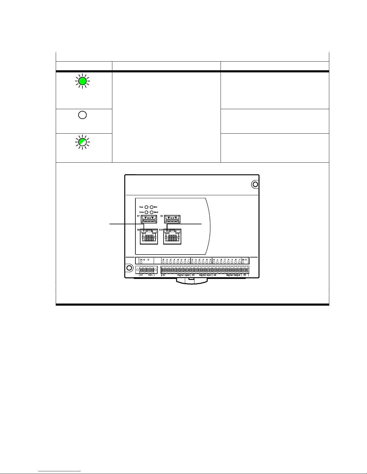
Speed LED
LED Status Description
LED illuminates
green
Speed ETH connection 1 Gbit/s
LED is off
100 Mbit/s
LED flashes
10 Mbps
1 1
1 Speed LED
Tab. 7.3 Speed LED, connections X8 and X10
Page 50
7 Diagnostics and error handling
50 Festo – SBRD-EN – 2017-11 – English
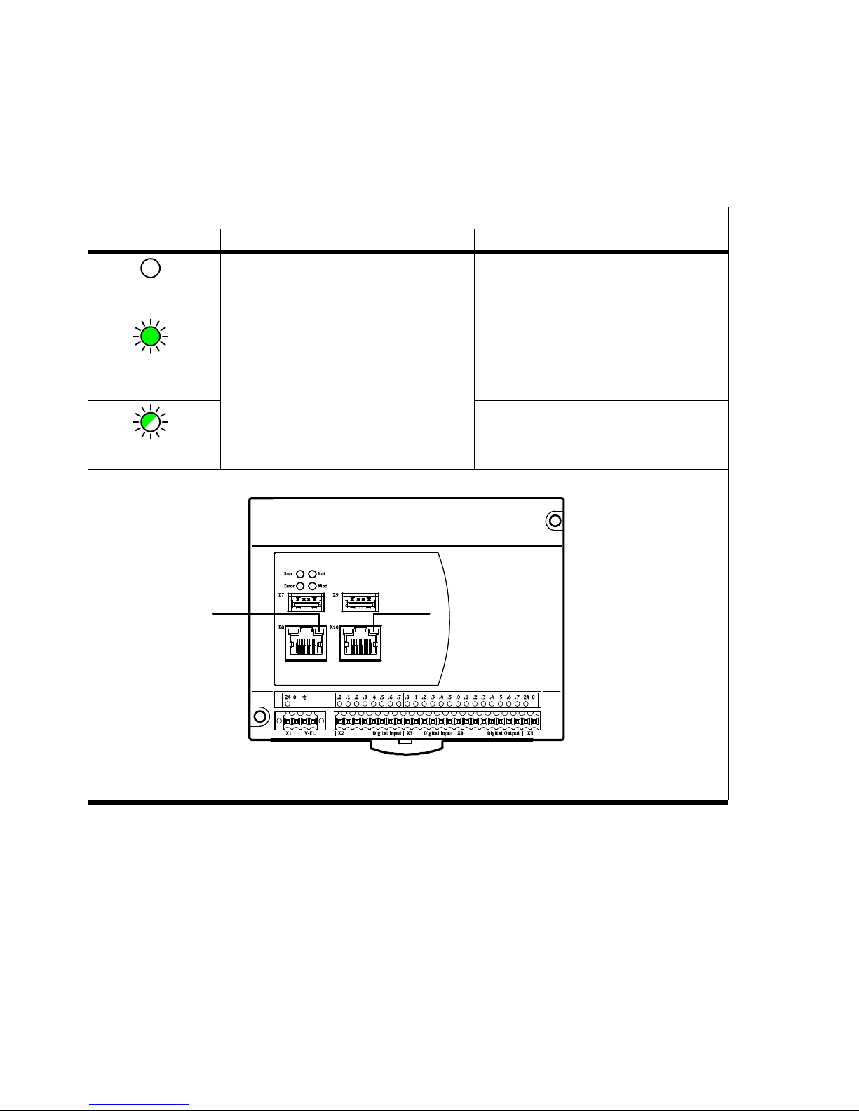
The Link/Traffic LED is activated independently of the link speed when an ETH connection exists.
This LED goes out briefly if data are sent or received. And so, in operation, active data traffic is signaled
by irregular flashing of the LEDs.
Link/Traffic LED
LED Status Description
LED is off
ETH connection No link
LED illuminates
green
Link
LED flashes
Traffic
1 1
1 Link/Traffic LED
Tab. 7.4 Link/Traffic LED, connections X8 and X10
Page 51

7 Diagnostics and error handling
Festo – SBRD-EN – 2017-11 – English 51
7.1.2 Error handling
Problem
Cause Measure
Device does not provide
evaluations.
Operating voltage is not present
or is below the permissible
tolerance.
Switch on operating voltage
or stay within tolerances.
Device is in the configuration
mode.
End configuration mode
in CCS software.
Job configuration is not correct Check job configuration
with CCS software.
Trigger signal is missing or has
incorrect polarity.
Check trigger signal.
Hardware error Service required
Evaluations of the device only
deliver images with the total
result not OK.
Incorrect parts type Diagnostics of the procedure
with CSS software
Job is not correct.
Job parameter is not correct. Check job configuration
with CCS software.
Firmware of the device remains
stuck.
Electromagnetic malfunction
from the environment due to
devices that are not
CE-conforming
Eliminate source of
malfunction.
Check for correct,
low-impedance screen
attachment of the connecting
cables of the camera system.
Use a separate power supply
unit only for the camera
system.
Wire functional earth
connections in accordance
with instructions.
Power supply not constant or
output of the power supply unit
is not sufficient.
Secure power supply as
specified.
Use power supply unit
with sufficient cable reserve.
Check parallel consumers.
Page 52

7 Diagnostics and error handling
52 Festo – SBRD-EN – 2017-11 – English
Problem MeasureCause
Image of the evaluation is
blurred or not sharp.
Device was moved,
e.g. through vibrations on
the machine/system.
Check mounting, reduce
vibrations.
Object is moving too fast. Reduce exposure time.
Motif lies outside the focus
range.
Maintain minimum distance,
dependent on the lens and
the camera.
If necessary, insert spacer
ring between camera and
lens.
Lens is not focused. Focus lens.
Optical errors are
in the evaluation image.
Lens or safety window is dirty. Carefully clean lens or safety
window.
CCS software cannot make
a connection to the camera
system.
Network is blocking the data
traffic.
Make sure that the router
passes on the multicast
address 239.255.2.3. If
necessary, ask the system
administrator.
Page 53

7 Diagnostics and error handling
Festo – SBRD-EN – 2017-11 – English 53
Problem MeasureCause
CCS software cannot make
a connection to the camera
system.
Network is blocking the data
traffic.
Make sure that the router
passes on the multicast
address 239.255.2.3.
If necessary, ask the system
administrator.
Network settings are not
compatible with each other.
Check the IP and sub-net
mask of the device and of
the PC.
Check the settings of
the intermediate network
components, such
as routers, etc.
No network connection. Check whether network
cables are correctly
connected.
Check the power supply of
the intermediate network
components, such
as routers, etc.
Firewall of the PC or network
does not permit a connection.
Enable program or ports
in firewall.
Network card of the PC is
deactivated, e.g. for notebook
without power supply.
Adjust Windows settings
è Energy options.
Device is already connected
with another program/user.
Disconnect other connection.
Cause not recognisable Reset device. Switch power
supply off and back on.
Windows error message Too little virtual memory free Comply with system
requirements
è Help for CCS.
Tab. 7.5 Error handling
Page 54

A Technical appendix
54 Festo – SBRD-EN – 2017-11 – English
G.2 Cleaning and maintenance
Caution
A dirty and scratched lens can result in optical errors.
Make sure that the lens is not scratched.
Do not use any abrasive cleaning agents.
Switch off operating voltage for cleaning.
Clean the lens in case of contamination or deposits: with a soft cloth and gentle cleaning agents.
Clean device as necessary. Cleaning agents include all non-abrasive media.
Page 55

A Technical appendix
Festo – SBRD-EN – 2017-11 – English 55
G.3 Siemens star
Fig. A.1 Siemens star
The Siemens star depicted here is a helpful template for rough focusing.
Page 56

A Technical appendix
56 Festo – SBRD-EN – 2017-11 – English
A Technical appendix
A.1 Technical data
SBRD-Q controller
General technical data
Type name code SBRD
Dimensions length x width x height [mm] 106 x 130 x 60
Type of mounting With H-rail
With through-hole for M4 screw
Product weight [g] 315
CE marking (see declaration of
conformity)
In accordance with EU EMC Directive
Protection against direct and indirect
contact
PELV
Nominal operating voltage DC [V] 24
Permissible voltage fluctuations [%] ± 10
Power consumption 24 V [W] 20
Current consumption with load-free
outputs
[mA] < 300 nominal at 24 V DC
Supply voltage cable length [m] < 30
Functional earth, connection M4
Input/output interface
Input/output interface, function 2x digital input with integrated pull-up
resistor
10x digital input
8x digital output
Power supply
Ground
Input/output interface, connection type Plug connector
Number of inputs 12
Note on inputs 2 of the 12 inputs with integrated pull-up
resistor
Switching level [V] Logic 0: 1
Logic 1: 10
Information on the switching level
1)
[V] Logic 0: 1
Logic 1: 8
Switching logic inputs PNP (positive switching)
Digital inputs, status indication LED
Digital inputs, permissible length of
the connecting cable
[m] < 30
1) For inputs with integrated pull-up resistor
Page 57

A Technical appendix
Festo – SBRD-EN – 2017-11 – English 57
Input/output interface
Number of outputs 8
Nominal operating voltage DC load [V] 24
Digital outputs, output current [mA] 450
Switching logic at outputs PNP (positive switching)
Digital outputs, contact Transistor
Digital outputs, short circuit protection Yes
Digital outputs, status indication LED
Digital outputs, permissible length of
the connecting cable
[m] < 30
Camera interface
Camera interface, function Exclusively communication with camera
Camera interface, connection type 2x socket
Camera interface, connectors USB compatible 3.0 type A
Information on the camera interface Use only the cables shown by Festo as
accessories è www.festo.com/catalogue.
Ethernet interface
Ethernet interface, protocol TCP/IP
Ethernet interface, function Diagnostics, programming
Ethernet interface, connection type Socket
Ethernet interface, connectors RJ45
Ethernet interface, number of pins/wires 8
Ethernet interface, transmission speed [Mbps] 10/100/1000
Fieldbus interface
Fieldbus interface, function Without function
Card slot
Memory card microSD
Storage capacity GB 32
File system FAT32
Immissions/emissions
Storage temperature [°C] -20 … +70 °C
Degree of protection IP20
Ambient temperature [°C] -5 … +50 °C
Relative humidity 95 %, non-condensing
Interference immunity Industrial environment in accordance
with EN 61000-6-2:2005
Interference emission Industrial environment in accordance
with EN 61000-6-4:2007 + A1:2011
Resistance to shocks Severity level 2 in accordance with EN60068
and FN 942017
Vibration resistance Severity level 2 in accordance with EN 60068
and FN 942017
Continuous shock resistance Severity level 2 in accordance with EN 60068
and FN 942017
1) For inputs with integrated pull-up resistor
Page 58

A Technical appendix
58 Festo – SBRD-EN – 2017-11 – English
Immissions/emissions
Corrosion resistance class [CRC] 0
PWIS criterium PWIS-free in accordance with FN 942010
Materials/other
Information on housing materials PA6 reinforced
PA6-GB20, GF10/LG-K2
Note on materials RoHS-compliant
1) For inputs with integrated pull-up resistor
Tab. A.1 Technical data
Page 59
A Technical appendix
Festo – SBRD-EN – 2017-11 – English 59
SBPB camera head
General technical data
Type code SBPB-R2 SBPB-R5 SBPB-R9
Type name code SBPB
Sensor resolution [pixels] 1280x1024
(SXGA)
1600x1200
(UXGA)
2456x2054
(5Mpix)
Lens mounting C mount
Field of view Dependent on the selected lens
Length x width x height [mm] 29 x 29 x 49
Type of mounting With mounting kit
Product weight [g] 52
CE marking (see declaration of
conformity)
In accordance with EU EMC Directive
USB-compatible interface
USB-compatible interface, function Power supply, communication
USB-compatible interface, connection
type
Socket
USB-compatible interface, connectors USB 3.0, type B micro
USB-compatible interface, number or
pins/wires
10
USB-compatible interface, type of
mounting
Screw-type lock
Nominal operating voltage DC [V] 5
Permissible voltage fluctuations [%] ± 5
Max. current consumption with load-free
outputs
[mA] 300 300 600
Electrical power consumption [W] 1.3 … 1.5 1.3 … 1.5 2.3 … 3
Input/output interface
Input/output interface, function Without function
Input/output interface, connection type Socket
Input/output interface, connectors HR25, Hirose HR25-7TR-8PA (73)
Input/output interface, number of pins
wires
8
Input/output interface, type of mounting Screw-type lock
Number of digital inputs 1
Switching input Optocoupler
Switching level Logic 0: 1 V
Logic 1: 5 V … 24 V
Min. input resistance [kOhm] 3
Voltage range [V] Max. 30
Page 60

A Technical appendix
60 Festo – SBRD-EN – 2017-11 – English
Type code SBPB-R9SBPB-R5SBPB-R2
Input/output interface
Pulse width trigger [μs] Min. 10
Edge steepness trigger [V/ms] Min. 35
Disruptive discharge voltage [V] Max. 50
Input current [mA] Max. 10
Number of digital outputs 1
Switching output, Optocoupler
Max. output current (short time) [mA] 500
Output current, permanent [mA] 150
Output voltage [V] Max. 30
Disruptive discharge voltage [V] Max. 50
Transistor loss power [mW] Max. 125
Short circuit protection No
Immissions/emissions
Storage temperature [°C] - 20 … + 60
Degree of protection IP30
Note on degree of protection In assembled state
Ambient temperature [°C] 0 … + 40
Relative humidity [%] 20 … 80
Interference immunity EN 61000-6-2:2005
Interference emission EN 61000-6-3:2007 + A1:2011
Resistance to shocks Shock test SL2 in accordance with FN/EN
FN 942017-5 and EN 60068-2-27
Vibration resistance Transparency and discharge inception test SL2
according to FN/EN in accordance
with EN 60068-2-6
Corrosion resistance class CRC 2
PWIS criterium PWIS-free in accordance with FN 942010
Electronics
Sensor types SBPB- … B monochrome
SBPB- … C colour
Sensor type CMOS global shutter
Frame rate (full screen) [fps] 60 60 36
Working distance Dependent on the selected lens
Sensor size [inch] 1/1.8 2/3
Aspect ratio 5:4 4:3 5:4
Exposure time 9 μs …
2,000 ms
20 μs …
10,000 ms
27 μs …
999 ms
Pixel size [mm] 0.0053 0.0045 0.00345
Binning factor 2 –
Sub-sampling factor – 2, 4, 6, 8, 16
Materials/other
Information on materials – housing Wrought aluminium alloy, anodised
Page 61
A Technical appendix
Festo – SBRD-EN – 2017-11 – English 61
Type code SBPB-R9SBPB-R5SBPB-R2
Materials/other
Note on materials RoHS-compliant
Ambient conditions Dry, screened from external light sources,
cleanest possible ambient air
Tab. A.2 Technical data
Note
Material damage due to incorrect cleaning.
Clean product only with non-abrasive cleaning agents and a soft cloth.
NEBC connecting cable
General technical data
Type name code NEBC
Cable designation Without label holder
Product weight [g] 282
Electrical connection 1
Function Field device side
Design Corner
Connection type Plug connector
Cable outlet Straight
Connection technology USB compatible 3.0, type B micro
Number of pins/wires 10
Assigned pins/wires 9
Tightening torque [Nm] 0.4
Tightening torque tolerance [%] ± 20
Electrical connection 2
Function Controller side
Design Corner
Connection type Plug connector
Cable outlet Straight
Connection technology USB compatible 3.0 type A
Number of pins/wires 9
Assigned pins/wires 9
1) Corrosion resistance class CRC in accordance with Festo standard 940070
Page 62

A Technical appendix
62 Festo – SBRD-EN – 2017-11 – English
Electronics
DC operating voltage range [V] 0 … 30
Acceptable current load at 40 °C [A] 0.25
Surge resistance [kV] 0.3
Cable
Cable length [m] 5
Cable characteristics Standard
Test conditions, cable Test conditions according to request
Bending radius, fixed cable installation [mm] > 125
Bending radius, flexible cable installation [mm] > 125
Cable diameter [mm] 7.3
Nominal conductor cross section [mm2] 0.21/ 0.26
Nominal conductor cross section [AWG] 23, 24
Immissions/emissions
Degree of protection IP20
Ambient temperature [°C] - 20 … + 80
Ambient temperature with flexible cable
installation
[°C] - 20 … + 80
PWIS criterium PWIS-free in accordance with FN 942010
Note on materials RoHS-compliant, halogen-free
Degree of contamination 1
Corrosion resistance class
1)
0
Materials/design
Cable sheath material PVC
Cable sheath colour Black
1) Corrosion resistance class CRC in accordance with Festo standard 940070
Tab. A.3 Technical data
Page 63
A Technical appendix
Festo – SBRD-EN – 2017-11 – English 63
A.2 Error messages
Name Description
General errors
E00 No error
E12
1)
Excessive temperature
Teach errors
E20 Errors in the job, orientations cannot be separated.
E21 Errors in the job, types or orientations cannot be
separated.
Errors in image generation
E31 Errors in generation of the images
E34 Connection between control unit and at least one camera
was interrupted.
E35 During loading of a job, no suitable camera could be
found.
Error in jobs or job parameters
E40 Job cannot be read/found.
E41 Job parameters cannot be read/interpreted.
E43 Job is not compatible with firmware. At least one of
the following checks has not been passed:
– Job may be used with firmware version.
– Settings for the tools are compatible with the firmware
version.
– Settings for the protocol-based I/O are compatible
with the firmware version.
– Required job license is present on camera system.
E45 Job could not be activated/loaded. – New attempt is
started after Acknowledge error signal.
E50 Power supply error: Power supply at X1 has fallen below
the minimum allowed value.
E51 Excess current error: Max. allowed current at the outputs
has been exceeded.
E52 Power supply error: Voltage supply at X5 is not present.
1) Error can be configured
Tab. A.4 Error messages
Page 64
A Technical appendix
64 Festo – SBRD-EN – 2017-11 – English
A.3 Address table for Telnet and Telnet-XML
Through Telnet, the following entries can be accessed for reading and/or writing.
The entries have the access type flag word (FW).
Note
Depending on the programming environment, flag word (FW) is also designated
as flagword.
A.3.1 Input register
Name
Read/
Write
FW Value
Type
Allowed Values Comments
Trigger signal R/W 0 Uint16 0 or 1
“Apply Inputs” signal R/W 1 Uint16 0 or 1
Acknowledge error signal R/W 2 Uint16 0 or 1
Not used 3 Uint16
Not used 4 Uint16
Not used 5 Uint16
Not used 6 Uint16
Not used 7 Uint16
Job preselection bit 0 R/W 8 Uint16 0 or 1 Takeover of
the preselected job
by setting the input
takeover signal.
The job preselection
is binary coded (bit 0 –
bit 7). Value range
(decimal) 1–255.
During reading, the
currently used job
number is returned.
Job preselection bit 1 R/W 9 Uint16 0 or 1
Job preselection bit 2 R/W 10 Uint16 0 or 1
Job preselection bit 3 R/W 11 Uint16 0 or 1
Job preselection bit 4 R/W 12 Uint16 0 or 1
Job preselection bit 5 R/W 13 Uint16 0 or 1
Job preselection bit 6 R/W 14 Uint16 0 or 1
Job preselection bit 7 R/W 15 Uint16 0 or 1
Tab. A.5 Input register
A.3.2 Output register
Name Read/
Write
FW Value
Type
Comments
Ready for operation R 16 Uint16
Output result OK R 17 Uint16
Output result not OK R 18 Uint16
Output result correctly oriented R 19 Uint16
Output result incorrectly oriented R 20 Uint16
Configuration mode R 21 Uint16
Warning R 22 Uint16
Page 65
A Technical appendix
Festo – SBRD-EN – 2017-11 – English 65
Name CommentsValue
Type
FWRead/
Write
Error status R 23 Uint16
Detected parts type bit 0 R 24 Uint16 Independent of the job parameter
output module format.
Detected parts type is binary coded
(bit 0 to bit 7):
00000000 = parts type 1
00000001 = parts type 2
…
11111111 = parts type 256
Detected parts type bit 1 R 25 Uint16
Detected parts type bit 2 R 26 Uint16
Detected parts type bit 3 R 27 Uint16
Detected parts type bit 4 R 28 Uint16
Detected parts type bit 5 R 29 Uint16
Detected parts type bit 6 R 30 Uint16
Detected parts type bit 7 R 31 Uint16
Tab. A.6 Output register
A.3.3 Quick access to input and output register
Name
Read/
Write
FW Value
Type
Allowed
Values
Comments
Quick access to
detected parts type
R 32 Uint16 Corresponds to flag word 24 to 31
Quick access to job
preselection
R/W 33 Uint16 1 to 255
during
writing
Corresponds to flag word 8 to 15.
For takeover, the input takeover
signal must then be set. During
reading, the currently used job
number is returned.
Tab. A.7 Quick access to input and output register
A.3.4 Extended system status/system information
Name Read/
Write
FW Value
Type
Comments
Error code of
the current error
R 100 Uint16 0 = No error
X = Error number (table in Chapter A.2)
Error code of
the current warning
R 101 Uint16 0 = No error
X = Error number (table in Chapter A.2)
Device type R 102 Uint16 SBRD: 714
Version of the major
firmware
R 103 Uint16 For example, Version 3.2.0.9:
high byte = 3, low byte = 2
Version of the minor
firmware
R 104 Uint16 For example, Version 3.2.0.9:
high byte = 0, low byte = 9
Page 66

A Technical appendix
66 Festo – SBRD-EN – 2017-11 – English
Name CommentsValue
Type
FWRead/
Write
Connection to the PC R 130 Uint16 0 = Device is not connected to the PC
1 = Device is connected, e.g. with CCS software
Tab. A.8 Extended system status/system information
A.3.5 System time of the device
Name Read/
Write
FW Value
Type
Allowed
Values
Comments
Date – year R/W 150 Uint16 2000 to
9999
System time of the device is capacitor-buf
fered. After disconnection from the power
supply for several weeks, the system time
must be reset.
Date – month R/W 151 Uint16 1 to 12
Date – day R/W 152 Uint16 1 to 31
Time – hours R/W 153 Uint16 0 to 23
Time – minutes R/W 154 Uint16 0 to 59
Time – seconds R/W 155 Uint16 0 to 59
Tab. A.9 System time
A.3.6 Overall tolerance of the type in the current job
Name Read/
Write
FW Value
Type
Allowed
Values
Comments
Parts type 0 R/W 200 Uint16 0 to 20 To store changed values permanently:
perform STOREPRG command.
Parts type 1 R/W 201 Uint16 0 to 20
Parts type 2 R/W 202 Uint16 0 to 20
Parts type 3 R/W 203 Uint16 0 to 20
Parts type 4 R/W 204 Uint16 0 to 20
Parts type 5 R/W 205 Uint16 0 to 20
Parts type 6 R/W 206 Uint16 0 to 20
Parts type 7 R/W 207 Uint16 0 to 20
Parts type 8 R/W 208 Uint16 0 to 20
Parts type 9 R/W 209 Uint16 0 to 20
Parts type 10 R/W 210 Uint16 0 to 20
Parts type 11 R/W 211 Uint16 0 to 20
Parts type 12 R/W 212 Uint16 0 to 20
Parts type 13 R/W 213 Uint16 0 to 20
Parts type 14 R/W 214 Uint16 0 to 20
Parts type 15 R/W 215 Uint16 0 to 20
Tab. A.10 Overall tolerance of the type in the current job
Page 67

A Technical appendix
Festo – SBRD-EN – 2017-11 – English 67
A.3.7 Basic results of the last test
Name
Read/
Write
FW Value
Type
Comments
Job name R 234 Byte (32) Name of the job of the last test
Job used R 250 Uint16 1 … 255
Mode used R 251 Uint16 0 = Teach, 2 = Auto
Detected parts type R 252 Uint16 1 … 16
Detected orientation R 253 Uint16 1 … 8
Run mode:
– Detection quality
R 254 Uint16 Run mode:
– Detection quality 0 … 999
– Image with overall result OK 0 … 100
– Image with overall result not OK > 100
Orientation quality R 255 Uint16 Orientation quality
Overall tolerance used R 256 Uint16 Overall tolerance used for testing the part
Part no. low word
(LSW)
R 257 Uint16 Part no. is binary coded with 32 bits and
distributed among 2 FW:
FW257 = 1 bit 1 … 16 (LSW)
FW258 = 1 bit 17 … 32 (MSW)
Example:
Part no. 500.000
FW257 = 1010 0001 0010 0000
FW258 = 0000 0000 0000 0111
Part no. high word
(MSW)
R 258 Uint16
Date – year of
the image
R 259 Uint16 With trigger signal
Date – month of
the image
R 260 Uint16 With trigger signal
Date – day of
the image
R 261 Uint16 With trigger signal
Time – hours of
the image
R 262 Uint16 With trigger signal
Time – minutes of
the image
R 263 Uint16 With trigger signal
Time – seconds of
the image
R 264 Uint16 With trigger signal
Processing time R 265 Uint16 Processing time of the part in ms from trigger
signal, up to max. 32 s
Page 68

A Technical appendix
68 Festo – SBRD-EN – 2017-11 – English
Name CommentsValue
Type
FWRead/
Write
Number of all
characteristics used
R 266 Uint16 Number of all characteristics that were
previously configured in the CCS software
in the selected job for testing of objects
è Job Navigator, step 4, Prepare test or Job
Navigator, step 5, Test objects.
Number of
characteristics that are
defined in the result
flag word
R 267 Uint16 Only those characteristics are considered that
were previously configured in the CCS
software in the selected job for output of
result flag words è Job Navigator, step 6,
Configure I/O, selection result flag words.
Summary of
the characteristic
results
R 300 –
315
Uint16 Results of up to 256 characteristics are
summarised at bit level for every 16 bits
(= 1 flag word).
Characteristic result:
0 = Not OK, 1 = OK
Only those characteristic results are
considered that were previously configured
in the CCS software in the selected job for
output of result flag words è Job Navigator,
step 6, Configure I/O, selection result flag
words.
Tab. A.11 Basic results of the last test
A.3.8 Freely usable flag words (not remanent)
Name Read/
Write
FW Value
Type
Comments
Free flag words (not
remanent)
R/W 320 –
383
Uint16 Flag words are 16 bit memory locations to which
no function is assigned as standard. Flag words
are filed in the main memory of the camera
system, but not permanently stored. The data
in these flag words are lost when the power
supply is switched off.
Tab. A.12 Freely used flag words (not remanent)
A.3.9 Configure cameras
Addressing of the cameras is summarised in sections. The sections begin with flag word 1000 and are
each offset by 500.
– Section of the 1st camera begins with 1000.
– Section of the 2nd camera begins with 1500.
Page 69
A Technical appendix
Festo – SBRD-EN – 2017-11 – English 69
The sections have the same structure, and are each offset by 500.
Name
Read/
Write
FW Value
Type
Comments
Exposure time R/W 1000 Double64 Exposure time of Camera 1 in microseconds.
Amplification R/W 1004 Uint16 0 … 100
Field of view left R/W 1005 Uint16 Area of field of view of the left sensor edge
in pixels
Field of view below R/W 1006 Uint16 Area of field of view of the lower sensor edge
in pixels
Field of view width R/W 1007 Uint16 Width of the field of view in pixels
Field of view height R/W 1008 Uint16 Height of the field of view in pixels
Tab. A.13
If no valid values are specified when writing, the next valid value is set.
Write access is made only to the data in RAM. To store the changed values remanently, perform
the STOREPRG command. Read and write access is only possible to connected cameras that are
assigned to the current job.
A.3.10 Characteristics – results of the last test
Addressing of the characteristic values is summarised in sections. The sections begin with flag word
10000 and are each offset by 100.
– Section of the first characteristic values begins with 10000
– Section of the second characteristic values begins with 10100
– Etc.
The number and sequence of the available characteristic sections is oriented on a protocol-based I/O
contained in the job of type Result flag word. For configuration, with the help of the CCS software,
the protocol-based I/O result flag word is added to the job and then the desired characteristics as
signed è Job Navigator, step 6, Configure I/O, selection Result flag words. The number of the actually
used characteristics is contained in flag word 267 è Tab. A.11.
Note
For each characteristic, the respective Valid-Flag flag word contains the information
on whether the characteristic could actually be calculated in the test.
If a very large negative number is a result of the characteristic, calculation of
the characteristic probably failed. A query of the Valid-Flag is unnecessary.
Page 70

A Technical appendix
70 Festo – SBRD-EN – 2017-11 – English
Name Read/
Write
FW
1)
Value Type Comments
Characteristic value R 10000 Double64
Tolerance R 10004 Double64 Tolerance used for characteristic
(incl. tolerance factor)
Characteristic value,
transformed
R 10008 Double64 Transformed characteristic value,
e.g. after coordinate transformation
Characteristic value
as text
R 10012 Byte[64] Characteristic value as string
Tool name R 10044 Byte[32] Name assigned by the user (cut off,
if necessary)
Characteristic name R 10060 Byte[32] Fixed characteristic name (cut off,
if necessary)
Valid-Flag R 10076 Uint16 – 1 = Characteristic could not
be calculated
– 0 = Calculation failed
Characteristic type R 10077 Int 16 ID of the characteristic type
Deviation R 10078 Int 16 Deviation (–32000 … 32000),
Deviation with overall result
OK = 100 … 100
Characteristic value,
before the decimal point
R 10079 Int 16 Characteristic value digits before
the decimal point as an integer
– Maximum value: 32767
– Minimum value: 32768
Characteristic value,
after the decimal point
R 10080 Uint16 Characteristic value digits after
the decimal point x 10,000 as
an integer2).
Valid-Flag from
the transferred
characteristic value
R 10081 Uint16 Use e.g. after coordinate transformation
– 1 = Characteristic value,
transformed could be calculated
– 0 = Calculation failed
Characteristic description R 10082 Uint16 ID of the characteristic description
Characteristic description
of the transformed
characteristic value
R 10083 Uint16 ID of the characteristic description of
the transformed characteristic value
1)
Example for the section of the first characteristic values from flag word 10000.
2)
Example: 0.99 is stored as 9900.
Tab. A.14 Characteristics – results of the last test
Page 71
A Technical appendix
Festo – SBRD-EN – 2017-11 – English 71
The available characteristics depend on the job and the firmware version of the device.
Note
Contact your regional Festo contact person if you have technical questions
è www.festo.com.
A.3.11 Job parameter
Name Read/
Write
FW Value Type Allowed Values
Job parameter R/W 7000 Uint16 è Dynamic help in the job parameter window of
the CCS software
Tab. A.15 Job parameter
Page 72

Reproduction, distribution or sale of this document or communica
tion of its contents to others without express authorization is
prohibited. Offenders will be liable for damages. All rights re
served in the event that a patent, utility model or design patent is
registered.
Copyright:
Festo AG & Co. KG
Ruiter Straße 82
73734 Esslingen
Germany
Phone:
+49 711 347-0
Fax:
+49 711 347-2144
E-mail:
[email protected]
Internet:
www.festo.com
 Loading...