

Festo MX-2-1/4, MX-2-* **-MS Series, MX-2 Series, MX-2-3/8, MX-2-3/4-B Operating Instructions Manual
...Page 1
326 744
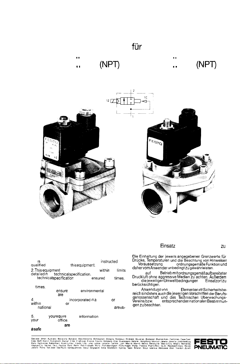
Operating Instructions Bedienungsanleitung
for solenoid valve
Type MX-2-.
MX-2-.
-MS
Magnetventil
Typ MX-2-.
MX-2-.
-MS
Conditions regarding the use of Festo
equipment.
This is important for reasons of safety
1 It
most important that only properly
personnel use
the
the
3 Correctly prepared compressed air should be used at
all
Customer shall
the place of use
If the equipment is
that
served.
These instructions are important. Please keep them in
safe place.
When Installing the equipment and thereafter. the
safety devices or circuits, the Customer shall ensure
and local safety laws and regulations
Should
local Festo
should only be used
that the
taken into consideration.
further
should be
Strict observance of
system or used
please contact
and
the
at all
conditions at
ob-
Was ist beim
beachten?
ist
Es ist
den
sind
Be!
die
von Festo Elementen
Festo
des
fur die
zu
an-
Page 2
Application
Valves of type MX are
shut-off valves. They are used to open and close
pilot
Typ MX sind
werden
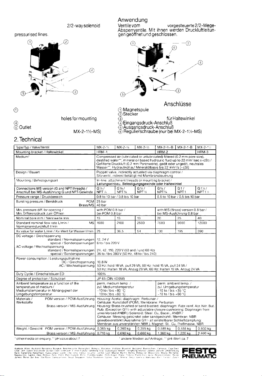
1. Operating parts and connections
Solenoid coil
@Plug
@Threaded attachment
Inlet pressure port
pressure port
@Regulating screw (only with
bracket
data
1. Bedienteile und
Befestigungsgewinde
Regulferschraube (nur
2. Technische Daten
Page 3
3. Installation
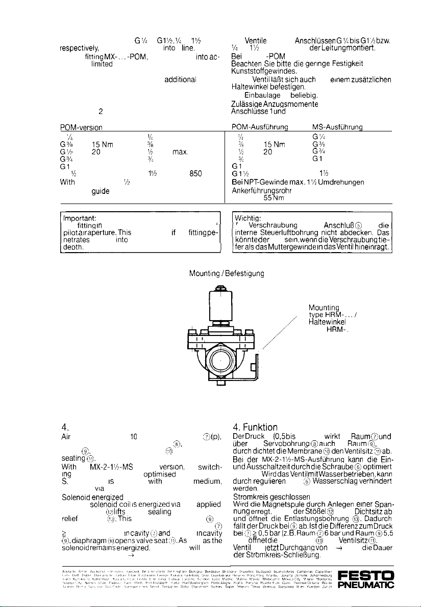
The valves threaded
When
count the
The valve can also be fitted to an
ing bracket.
The valve may be installed at any angle.
Permitted tightening torques
Ports 1 and
G
G 1
Armature
can be fitted direct
strength of the plastic thread.
5Nm
Nm
30 Nm
40 Nm Gl
60 Nm
NPT threads 1
55 Nm
tube
to
please take
Brass-version
G
G
G
G
G
turns maximum
a
max. 35 Nm
max. 60 Nm
max. 200 Nm
max. 380 Nm
max.
55 Nm
to
105 Nm
NPT
ac-
mount
Nm
3. Montage
Die
Das
Die
G
G
G
G
mit den
bis
NPT werden in der Leitung
MX-. -POM
la8t
ist
2
5Nm max. 35 Nm
Nm
30 Nm
40 60 Nm Nm
such an
max.
gennge
G
G
des
max. 60 Nm
max. 105 Nm
max. 200
max. max. 380 850
55 Nm
Nm
Nm Nm
The
port 2 @must not block the internal
air
can happen
the valve than the threaded
the fittrng
Function
pressure (0.5 to
passes through servo-passage
cavity (3. As a result, diaphragm
the
on and off time can be
If the valve
regulation vta S can prevent water hammer.
If the
voltage, stem off the sealing seat and opens
passage
drop If the pressure difference compared to
0.5 bar (e.g. 6 bar
through-flow from 1
bar) enters at port
(brass)
operated wrth water as
causes the pressure at
2.
the valve
and enters
seals off valve
the
through screw
an
5.5 bar)
long
cavrty
have
Die Verschraubung fur den
der Fall
P
die
werden.
geschlossen
to
bar)
hat )etzt Durchgang van 1
10 bar)
an
hebt der
(3
Membrane
wenn
Typ
(3 such im
bracket
im
vom Dichtsrtz
den
2 fur
darf
Dadurch
Da-
kann
Span-
Druck
Das
Page 4
If the
the relief
and the
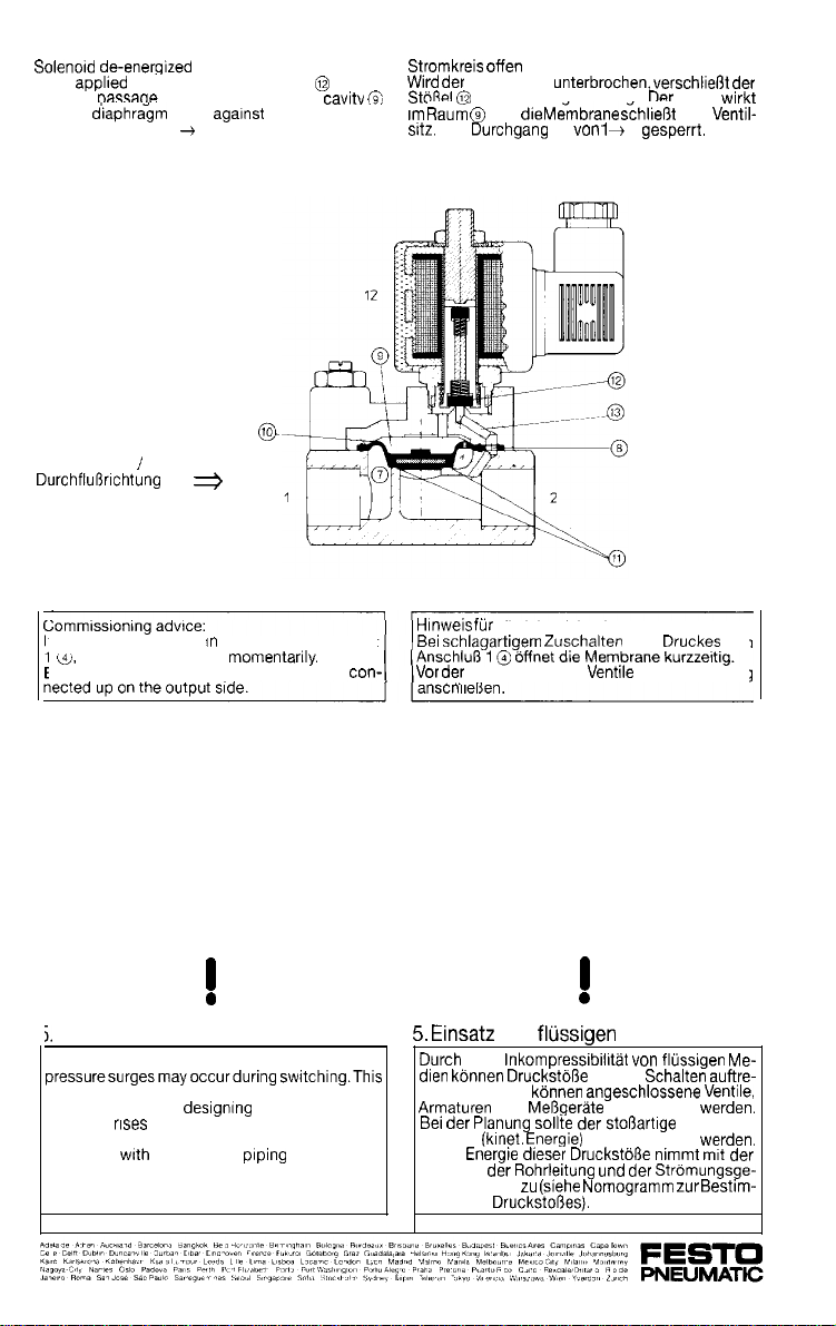
Through-flow from 1
Flow direction
If pressure is applied
1
Before commissioning, ensure the valve is
voltage is removed, stem
Pressure is effective in
seals agarnst the valve seat&.
2 is clocked.
the diaphragm opens
sudden bursts at port
closes
Stromkreis
die Entlastunasbohruna.
und
Der Durchgang ist
lnbetriebnahme
die lnbetriebnahme:
Druck
den Ventil-
2 gesperrt.
des
ausgangsseitig
am
A
Use of liquid media
Because liquid media are not compressible,
may cause damage to connected valves, fittings
and gauges. When
pressure
into account. The power of these pressure surges
Increases wrth the length of
velocity (see nomogram for determining the
pressure surge).
(kinetic energy) should be taken
a system, sudden
and with flow
A
von
und
Planung
ten. Dabei konnen
anstieg
Die
Lange der
schwindigkeit
mung des
Medien
van
beim
beschadigt werden.
der
berucksichtigt werden.
Druck-
Me-
der
Page 5
Problems can be associated with installations
where:
a) Flow velocities m/s occur
b) Supply pressure is static, e.g. high level
with a long pipe connection
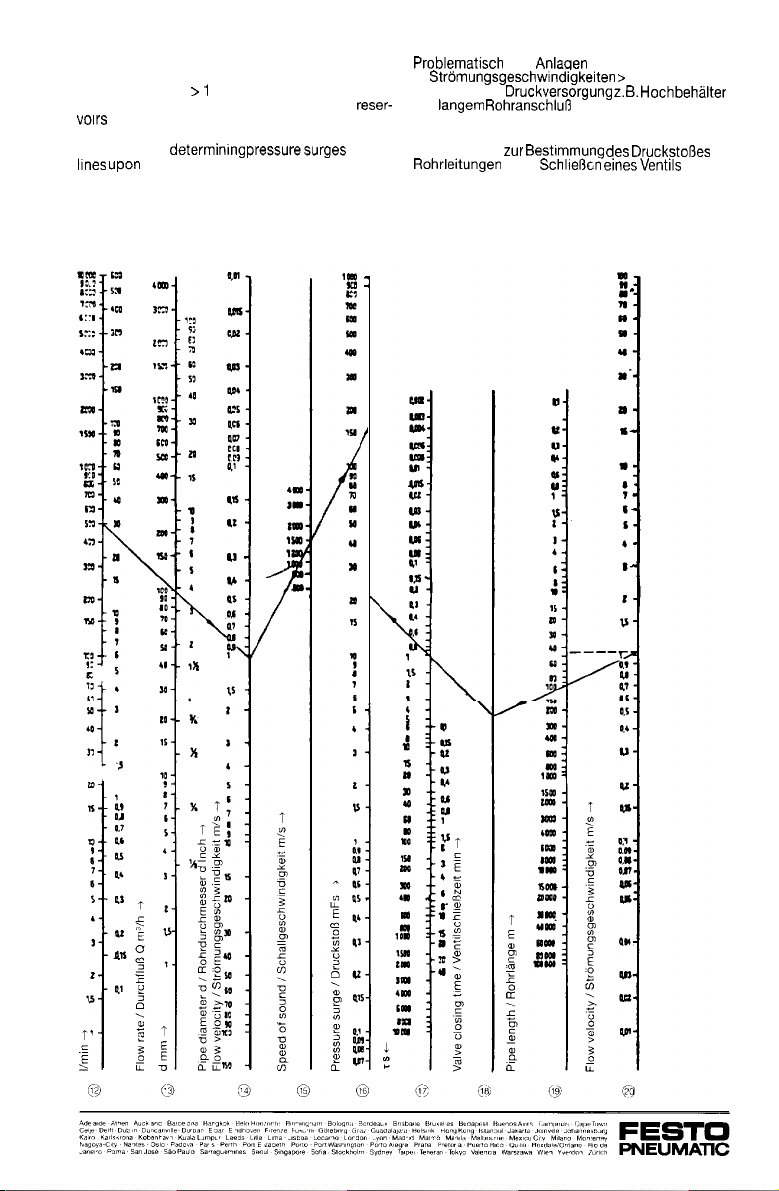
Nomogram for
valve closure
in pipe
a)
b) Statischer
mit
Nomogramm
sind Anlagen mit:
1 m/s
in
Page 6
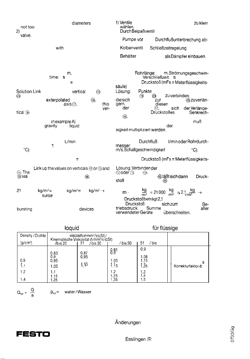
Remedies:
1) Select valve sizes and pipe
small.
Phased switching through use of a by-pass
3) Switch off pump before through-flow is inter-
rupted.
4) Use piston valve
lation.
5) Fit reservoirs with air cushions as damping de-
vices.
shutting-off time regu-
which are
Example A:
Required: Pipe length: 100
valve shutting-off
Wanted: Pressure surge (mlc
umn)
corresponding to the given data. The resulting
line should be
joins this point to vertical
line will give the value of the pressure surge on
The value read (21
by the specific
Example B:
Given: Through-flow: 500
mm, flow velocity:
(15
Required: Pressure surge (mlc
column)
Solution:
up the points on verhcal axes
1460 m/s
pressure surge may then be read on vertical
the speed of sound on vertical
m/s, speed of sound in water
of the
1
flow velocity: 1 m/s,
meters of liquid col-
up to axis
extension of
must be multiplied
If one
used.
or pipe bore: 100
metres of liquid
and
Example with water as medium:
m 1000
The pressure
The pressure surge has to be added to the static
operating pressure. The sum must not exceed the
21000
amounts to 2.1 bar.
pressure of any installed
2.1
Abhilfe:
und Fiohrdurchmesser nicht
2)
3)
schalten.
4)
5)
vor der
mit Luftpolster als Dampfer
Stufenschaltung.
mit
einsetzen.
Beispiel A:
Gegeben: Rohrlange: 100
digkeit: 1 m/s,
Gesucht:
Die
Senkrechten
Verbindet man
auf der Senkrechten
rung der Wert des
ten
Der abgelesene Wert (im Beispiel A: 21)
dem spezifischen Gewicht
Beispiel B:
Gegeben:
1460 m/s
Gesucht:
saule)
oder
auf der Senkrechten sich
und
ergibt, ist bis
multrplrzrert werden,
100 mm, Stromungsgeschwindigkeit: 1
der Werte auf den Senkrechten
und
Uber die Schallgeschwindigkeit
1
der gegebenen Daten auf den
sind
Senkrechten
Punkt mit dem Punkt
ergibt
in
auf der
verwendeten Flus-
500
in Wasser (15
ablesen.
Beispiel Medium Wasser:
21
Der
Der
1000
addiert
Die
Gerate nicht
!Y
bar.
darf den Berstdruck aller
cm2
statischen
klein
Die Linie,
mit
der
Correction factor for
Kinematic
to
0.6 0.75
0.7
0.8 0,9
1
1.3
= p
Subject to change
PNEUMATIC
Festo KG Postfach D-73726 Esslingen R (0711) 347-0 l 722 727
media Korrekturfaktor
mmpls (cSt)
(cSt)
0.8
1
1.15
1.2
1.3
to
31 to
1
to
1
a
vorbehalten
80
Medien
Correction factor
 Loading...