

Page 1
Motor unit
MTR−DCI
Manual
Type MTR−DCI−...
Type MTR−DCI−...IO
Manual
539 616
en 0411NH
[677 795]
Page 2

Adobe® and Reader® are either a registered trademark or a
trademark of Adobe Systems Incorporated in the United
States and/or other countries.
Page 3

Contents and general instructions
Author G. Neumann−Rasaei. . . . . . . . . . . . . . . . . . . . . . . . . .
Editor M. Holder. . . . . . . . . . . . . . . .
. . . . . . . . . . . . . . . . . . .
Original German text. . . . . . . . . . . . . . . . . . . . . . . . . . . .
Edition
Designation
Order no. 539 616 . . . . . . . . . . . . . . . . . . . . .
. . . . . . . . . . . .
. . .
en 0411NH. . . . . . . . . . . . . . . . . . . . . . . . . . . . . . . . . .
P.BE−MTR−DCI−EN. . . . . . . . . . . . . . . . . . . . . . . . .
E (Festo AG&Co. KG, D73726 Esslingen, Federal Republic of Germany, 2004)
Internet: http://www.festo.com
E−Mail: service_international@festo.com
The copying, distribution and utilization of
this document as
well as the communication of its contents to others without
expressed authorization is prohibited. Offenders will be
held liable for the payment of damages. All rights are re
served, in
particular the right to carry out patent, utility
model or ornamental design registration.
Festo P.BE−MTR−DCI−EN en 0411NH
I
Page 4

Contents and general instructions
II
Festo P.BE−MTR−DCI−EN en 0411NH
Page 5

Contents and general instructions
Contents
Designated use VII . . . . . . . . . . . . . . . . . . . . . . . . . . . . . . . . . . . . . . . . . . . . . . . . . . . . . . . .
Safety instructions VIII . . . . . . . . . . . . . . . . . . . . . . . . . . . . . . . . . . . . .
Target group IX . . . . . . . . . . . . . . . . . . . . . . . . . . . . . .
Service IX . . . . . . . . . . . . . . . . . . .
Scope of delivery IX
Important user instructions X . . . . . . . . . . . . . . . . . . . . . . . . . . . . . . . . . . . . . . . . . .
Product−specific terms and abbreviations XII . . . . . . . . . . . . . . . . . . . . . . . . . . . . . . . . . . .
Manuals on motor unit
Information on the version XVI .
. . . . . . . . . . . . . . . . . . . . . . . . . . . . . . . . . . . . . . . . . . . . . . . . . . . . . . .
type MTR−DCI XV . . . . . . . . . . . . . . . . . . . . . . . . . . . . . . . . . . . . . .
. . . . . . . . . . . . . . . . . . . . . . . . . . . . . . . . . . . . . . . . . . . .
. . . . . . . . . . . . . . . . . . . . . . . . . . . . . . . . . . . . . . . . . . . . . .
. . . . . . . . . . . . . . . . . . . . . . . . . . . .
. . . . . . . . . . . . . . . .
. . . .
1. Summary of components 1−1 . .
1.1 Positioning with intelligent drives 1−3 . . .
1.1.1 Method of operation 1−8 . . . . . . . . . . . . .
1.1.2 Reference coordinates and working area 1−10 . . . . . . . . . . . . . .
1.2EMERGENCY STOP concept 1−14 . . . . . . . . . . . . . . . . . . . . . . . . . . . . . . . . . . .
1.3 Possibilities of commissioning 1−15 . . . . . . . . . . . . . . . . . . . . . . . . . . . . . . . . . . . .
1.3.1 Control panel (MTR
1.3.2Festo Configuration Tool (FCT) 1−16 . . . . . . . .
2. Fitting 2−1 . . . . . . . . . . . . . . . . . . . . . . . . . . . .
2.1 General instructions 2−3 . . . . . . . . . . . . . . . . .
2.2 Dimensions of the motor unit 2−4 . . . . . . . . . . . . . .
2.3 Fitting electric axes2−5 . . . . . . . . . . . . . . . . . . . . .
3. Installation 3−1 . . . . . . . . . . . . . . . . . . . . . . . .
3.1 Overview of installation 3−3 . . . . . . . . . . . . . . . . .
3.2 Power supply 3−6 . . . . . . . . . . . . . . . . . . . .
3.3 Serial interface3−8 . . . . . . . . . . . . . . .
3.4 Input for external reference switch 3−10 . . . .
3.5 Connecting the higher−order controller 3−12 . . . . . . . . . .
. . . . . . . . . . . . . . . . . . . . . . . . . . . . . . . . . . . . . .
. . . . . . . . . . . . . . . . . . . . . . . . . . . . . . .
. . . . . . . . . . . . . . . . . . . . . . . .
. . . . . .
. . . .
−DCI−...−H2) 1−16 . . . . . . . . . . . . . . . . . . . . . . . . . . . . .
. . . . . . . . . . . . . . . . . . . . .
. . . . . . . . . . . . . . . . . . . . . . . . . . . .
. . . . . . . . . . . . . . . . . . . . . . . . . . . .
. . . . . . . . . . . . . . . . . . . . . . .
. . . . . . . . . . . . . . . . . . . . . . . . .
. . . . . . . . . . . . . . . . . . . . . . . . . . .
. . . . . . . . . . . . . . . . . . . . . . . . .
. . . . . . . . . . . . . . . . . . . . . . . . . . . . . .
. . . . . . . . . . . . . . . . . . . . . . . . . . . . . . . . . .
. . . . . . . . . . . . . . . . . . . . . . . . . . . . .
. . . . . . . . . . . . . . . . . . . .
Festo P.BE−MTR−DCI−EN en 0411NH
III
Page 6

Contents and general instructions
4. Control panel (MTR−DCI−...−H2−IO) 4−1 . . . . . . . . . . . . . . . . . . . . . . . . . . . . . . . .
4.1 Composition and function of the control panel 4−4 . . . . . .
4.2The menu system4−6 . . . . . . . . . . . . . . . . . . . . . . . . . . .
4.2.1 Accessing the main menu 4−6 . . . . . . . . . . . . . . . . . . . . .
4.2.2"Diagnostic" menu 4−8 . . . . . . . . . . . . . . . . . . . . . . . . . . . . . . . . .
. . . . . . . . . . . . . . . . .
. . . . . . . . . . . . . . . . . . . .
. . . . . . . . . . . .
. . . . .
4.2.3 Device control "HMI control" 4−10 . . . . . . . . . . . . . . . . . . . . . . . . . . . . . .
4.2.4"Settings" menu 4−11
4.2.5 "Positioning" menu 4−17 . . . . .
5. Commissioning 5−1 . . . . . . . . . . . . . . . . .
5.1 Preparing for commissioning 5−3 . . . . . . . . . . . . .
. . . . . . . . . . . . . . . . . . . . . . . . . . . . . . . . . . . . . . . .
. . . . . . . . . . . . . . . . . . . . . . . . . . . . . . . . .
. . . . . . . . . . . . . . . . . . . . . . . . . . . . . . .
. . . . . . . . . . . . . . . . . . . . . . . . .
5.1.1 Check the connection to the mains power supply.5−3 . . . . . . . . . . . .
5.1.2 Check the drive. 5−3 . . . . . . . . . . . . . . . . . . . . . . . . . . . . . . . . . . . . . . . . .
5.1.3 I
5.2 Procedure for commissioning 5−5 . . . . . . . .
5.2.1 Commissioning with FCT 5−8 . . . . . . . . . . . . . . .
nstalling and starting the FCT 5−4 . . . . . . . . . . . . . . . . . . . . . . . . . . . . .
. . . . . . . . . . . . . . . . . . . . . . . . . . . . .
. . . . . . . . . . . . . . . . . . .
5.2.2 Commissioning with control panel (MTR−DCI−...−H2) 5−10 . . . . . . . . . . . .
5.3 Parametrizing and ref
5.3.1 Setting the axis type5−12 . . . . . . . . . . .
5.3.2Setting the homing parameters 5−12 . . . . . . . . . . . . . . .
erencing (MTR−DCI−...H2) 5−12 . . . . . . . . . . . . . . . . . . . . . . .
. . . . . . . . . . . . . . . . . . . . . . . . . .
. . . . . . . . . . . . .
5.3.3 Carrying out homing 5−17 . . . . . . . . . . . . . . . . . . . . . . . . . . . . . . . .
5.3.4Teach the axis zero point and the software end positions.5−20 . . . . . . .
5.4 Positioning with position sets (MTR−DCI−...H2) 5−22 . . . . . . . . . . . .
5.4.1 Teach the position sets 5−23 . . . . . . . . . . . . . . . . . . . . . . . . . . . . .
5.4.2Test run 5−25 . . . . . . . . . . . . . . . . . . . . . . . . . . . . . . . . . . . . . . .
5.5 I/O function test 5−26 . . . . . . . . . . . . . . . . . . . . . . . . . . . . . . . . . . . .
5.6 Instructions on operation 5−27 . . . . . . . . . . . . . . . . . . . . . . . . . . . . . . . .
. . . . . . . . . . . .
. . . . . .
. . . . . . . .
. . . . . . . . . . . .
. . . . . . . . .
5.7 Diagnosis and fault display 5−31 . . . . . . . . . . . . . . . . . . . . . . . . . . . . . . . . . . . .
5.7.1 General diagnostic possibilities 5−31 . . . . . . . . . . . . . . . . . . . . . . . . . . . .
5.7.2LED status displays 5−32 . . . . .
5.7.3 Fault messages on the display (MTR−DCI−...H2) 5−34 . . . .
. . . . . . . . . . . . . . . . . . . . . . . . . . . . . . . . .
. . . . . . . . . . . .
.
. . . . .
. . .
IV
Festo P.BE−MTR−DCI−EN en 0411NH
Page 7

Contents and general instructions
6. Communication with the higher−order controller 6−1 . . . . . . . . . . . . . . . . . . . . .
6.1 Connecting the I/O interface6−3 . . . . . . . . . . . . . . .
6.2 Description of the I/Os 6−5 . . . . . . . . . . . . . . . . . . .
6.3 Function description (pulse−time diagram) 6−8 . . . . . . . . . . . . . . . . . .
6.4 I/O specification 6−11 . . . . . . . . . . . . . . . . . . . . . . . . . . . . . . . . . . .
. . . . . . . . . . . . . . . . . . . . . . .
. . . . . . . . . . . . . . . . . . . . . . . .
. . . . . . . . .
. . . . . . . . . . . . .
7. Communication via the serial interface 7−1 . . . . . . . . . . . . . . . . . . . . . . . . . . . . .
7.1 The Command
7.2 Procedure for data transf
7.3 Object directory 7−7 . . .
7.3.1 Objects for device
7.3.2General Objects 7−8 . . . . . . . . . . .
7.3.3 Objects for parametrizing and commissioning 7−8 . . . . . . . . . . . .
Interpreter (CI) 7−3 . . . . . . . . . . . . . . . . . . . . . . . . . . . . . . . . . . . . .
er 7−4 . . . . . . . . . . . . . . . . . . . . . . . . . . . . . . . . . . . . . . .
. . . . . . . . . . . . . . . . . . . . . . . . . . . . . . . . . . . . . . . . . . . . .
description 7−7 . . . . . . . . . . . . . . . . . . . . . . . . . . . . .
. . . . . . . . . . . . . . . . . . . . . . . . . . . . . .
. . . .
7.3.4 Objects for creating position sets 7−9 . . . . . . . . . . . . . . . . . . . . . . . . . . .
7.3.5 Objects for controlling 7−10 . .
7.3.6 Objects for setting the operating mode and control 7−10 . . .
. . . . . . . . . . . . . . . . . . . . . . . . . . . . . . . . . .
. . . . . . . . .
7.3.7 Objects for diagnosis 7−11 . . . . . . . . . . . . . . . . . . . . . . . . . . . . . . . . . . .
A. Technical appendix A−1 . . . . . . . . . . . . . . . . . . . . . . . . . . . . . . . . . . . . . . . . . . . . .
A.1 Technical
A.2 AccessoriesA−6 .
specifications A−3 . . . . . . . . . . . . . . . . . . . . . . . . . . . . . . . . . . . . . . . . . .
. . . . . . . . . . . . . . . . . . . . . . . . . . . . . . . . . . . . . . . . . . . . . . . . . . .
A.3 Motor characteristic curvesA−7 . . . . . . . . . . . . . . . . . . . . . . . . . . . . . . . . . . . . . . .
.
B. Supplementary information B−1 . . .
B.1 CI commands B−3 . . . . . . . . . . . .
B.2 Object description B−7 . . . . . .
B.2.1 Object classification (overview) B−8 . . .
B.2.2 Group 1xxx B−10 . . . . . . . . . . . . . . . . . . . .
B.2.3 Group 2xxx B−11 . . . . . . . . . . . . . . . . . . . . .
B.2.4 Group 6xxx B−21 . . . . . . . . . . . . . . . . . . . . . .
. . . . . . . . . . . . . . . . . . . . . . . . . . . . . . . . . . .
. . . . . . . . . . . . . . . . . . . . . . . . . . . . . . . . . . . . . .
. . . . . . . . . . . . . . . . . . . . . . . . . . . . . . . . . . . . . . . .
. . . . . . . . . . . . . . . . . . . . . . . . .
. . . . . . . . . . . . . . . . . . . . . . . . .
. . . . . . . . . . . . . . . . . . . . . . . .
. . . . . . . . . . . . . . . . . . . . . . .
B.3 Converting the measuring units B−41 . . . . . . . . . . . . . . . . . . .
C. Index C−1 . . . . . . . . . . . . . . . . . . . . . . . . . . . . . . . . . .
Festo P.BE−MTR−DCI−EN en 0411NH
. . . . . . . . . . . . . . . . . . . . . . .
. . . . . . . . . . . . . . . .
V
Page 8

Contents and general instructions
VI
Festo P.BE−MTR−DCI−EN en 0411NH
Page 9

Contents and general instructions
Designated use
The MTR−DCI motor unit is an intelligent servo motor consist
ing of DC motor, planetary gear, encoder and integrated con
trol electronics (positioning control and position regulator).
The mechanical layout and plug−in interface of the
MTR−DCI
have been optimized for use with electric linear drives (e.g.
type DMES...) from Festo. The motor unit can also be used
for customer−specific positioniing applications with slow
spindle drives.
This manual deals
with the basic functions of the MTR−DCI
and the I/O interface of the MTR−DCI−...I0. Additional compo
nents as well as the field bus variants of the MTR−DCI are de
scribed in separate manuals.
It is absolutely necessary to observe the "Technical safety
instructions" as well as the designated use of the relevant
components and modules. Observe also the safety instruc
tions in the ope
rating instructions for the electric components
used.
The MTR−DCI and the connectable modules and cables may
only be used as follows:
in accordance with designated use
only in industrial applications
without any modifications by the user Only
the conver
sions or modifications described in the documentation
supplied with the product are permitted.
in faultless technical condition.
Festo P.BE−MTR−DCI−EN en 0411NH
If additional commercially−available components such as sen
sors and actuators are connected, the specifi
ed limits for
temperatures, electrical data, torques, etc. must not be ex
ceeded.
Please observe the standards specified in the relevant
chapters and comply with technical regulations, as well as
national and local regulations.
with
VII
Page 10
Contents and general instructions
Safety instructions
When commissioning and programming positioning systems,
you must observe the safety regulations in this manual as
well as those in the operating instructions for the other com
ponents used.
The user must make sure that nobody is
in the operating
range of the connected actuators or axis system. Access to
the possible danger area must be prevented by suitable
measures such as protective screens and warning signs.
Warning
Electric axes can move suddenly with high force and at
high speed. Collisions can lead to serious injury to human
beings and damage to components.
Make sure that nobody can gain access to the operating
range of
the axis or of other connected actuators and that
no objects lie in the path of the axis while the system is still
connected to a power supply.
Warning
Faults in parametrizing can cause injury to people and
damage to property.
Enable the controller only if the axis system is correctly
installed and parametrized.
VIII
Festo P.BE−MTR−DCI−EN en 0411NH
Page 11

Contents and general instructions
Target group
This manual is intended exclusively for technicians trained in
control and automation technology, who have experience in
installing, commissioning, programming and diagnosing posi
tioning systems.
Service
Please consult your local Festo repair service at the following
e−mail address if you have any technical problems.
service_international@festo.com
Scope of delivery
The following items are supplied with motor unit type MTR−
DCI:
Festo P.BE−MTR−DCI−EN en 0411NH
motor unit with integrated controller, optional with control
panel
FCT configuration package (Festo Configuration Tool)
User documentation on CD ROM
available as accessory (see Appendix
connecting cable
user documentation in paper form
A.2)
IX
Page 12

Contents and general instructions
Important user instructions
Danger categories
This manual contains instructions on the possible dangers
which can occur if the product is not used correctly. These
instructions are marked (Warning, Caution, etc), printed on a
shaded background and marked additionally with a picto
gram. A distinction is
warnings:
Warning
... This means that failure to observe this instruction may
result in serious personal injury or damage to property.
Caution
... This means that failure to observe this instruction may
result in personal injury or damage to property.
made between the following danger
Please note
... This means that failure to observe this instruction may
result in damage to property.
The following pictogram marks passages in the text which
describe activities with electrostatically sensitive compo
nents.
Electrostatically sensitive components: These may be dam
aged if they are not handled correctly.
X
Festo P.BE−MTR−DCI−EN en 0411NH
Page 13

Contents and general instructions
Marking special information
The following pictograms mark passages in the text contain
ing special information.
Pictograms
Information:
Recommendations, tips and references to other sources of
information.
Accessories:
Information on necessary or useful accessories for the Fe
product.
Environment:
Information on the environment−friendly use of Festo prod
ucts.
sto
Festo P.BE−MTR−DCI−EN en 0411NH
Text markings
· The bullet indicates activities which may be carried out in
any order.
1. Figures denote activities which must be carried out in the
numerical order specified.
Hyphens indicate general activities.
XI
Page 14

Contents and general instructions
Product−specific terms and abbreviations
The following product−specific terms and abbreviations are
used in this manual:
Term/abbreviation
0−signal There is a 0 V signal at the input or output.
1−signal There is a 24 V signal at the input or output.
Axis zero point (AZ) Measuring reference point for the project zero point and the software
Axis Complete actuator, consisting of controller, motor, encoder, if appli
Drive Mechanical component of an axis which defines the guide for the posi
Controller Control electronics which evaluate the control signals and provide the
DMES... Typ e designation, electric linear axis
E
A
I/O
EMC Electromagnetic compatibility
Encoder with MTR−DCI: optical pulse generator (rotor position transducer). The
Meaning
end positions. Corresponds to the project zero point in the MTR−DCI
(offset = 0). The reference point for the axis zero point is the reference
point.
cable, gear and drive.
tioning movement, and enables the work load and the reference
switch to be fitted. An example of a drive is the linear drive type
DMES...
power supply for the motor via the power electronics.
Input
Output
Input and/or output
electric signals generated are sent to the controller, which then calcu
lates the position and speed on the basis of the signals received.
FCT Festo Configuration Tool, software with uniform project and data man
Motor unit Integrated unit consisting of a controller and motor, e.g. motor unit
XII
agement for all supported device types. The special wishes of a device
type are supported by PlugIns with the necessary descriptions and
dialogues.
type MTR−DCI.
Festo P.BE−MTR−DCI−EN en 0411NH
Page 15

Contents and general instructions
Term/abbreviation Meaning
Positioning mode
(Profile Position mode)
Position registering
(quasi−absolute)
Project zero point (PZ) Measuring basis point for all positions in positioning tasks (Project
Referencing
(Homing mode)
Reference point (REF) Zero point of the axis which is defined by reference travel (homing).
Reference switch External sensor (e.g. type SME−8/SMT−8 or SIEN−...) which serves for
Referencing method Method for defining the reference position: against a fixed stop (over
Homing The reference position and therefore the source of the measuring
Operating mode for processing a position set.
If there is a power failure, the actual position will be saved in a non−
volatile memory. Depending on the application this means that if self−
locking drives are used, (new) homing will not be necessary when the
device is switched on again.
Zero point). The project zero point forms the basis for all absolute
position specifications (e.g. in the position set table or with direct
control via the control or diagnostic interface). Basis point for the
project zero point is the axis zero point (on the MTR−DCI the project
zero point PZ and the axis zero point AZ are identical).
Operating mode in which homing is carried out.
On electric axes the zero point can be shifted to the axis zero point
(offset axis zero point).
ascertaining the reference position and is connected directly to the
MTR−DCI.
current/speed evaluation) or with reference switch.
reference system of the axis will be defined by the reference travel.
PLC Programmable logic controller; in brief: controller
Software end position Programmable stroke limitation (reference point = axis zero point)
Teach mode
(Teach mode)
Festo P.BE−MTR−DCI−EN en 0411NH
Software end position, positive:
Max. limit position in positive direction (away from the motor); must
not be exceeded during positioning.
Software end position, negative:
Min. limit position in negative direction (towards motor). Value must
not sink below this level during positioning.
Operating mode for setting positions by moving to the target position
e.g. when creating position sets.
XIII
Page 16

Contents and general instructions
Term/abbreviation Meaning
Tip mode Manual positioning in positive or negative direction (only on field bus
Position set Positioning command defined in the position set table, consistin of
variants of the MTR−DCI or only with FCT )
target position, positioning mode and positioning speed. Maximum 15
position sets are possible on the MTR−DCI with I/O control.
Table.0/1: Index of terms and abbreviations
XIV
Festo P.BE−MTR−DCI−EN en 0411NH
Page 17

Contents and general instructions
Manuals on motor unit type MTR−DCI
This manual contains basic general information on operating,
fitting, installing and commissioning electric servo drives
with motor unit type MTR−DCI−.... It also contains information
on the functions of the I/O interface for type MTR−DCI−..IO as
ell as on commissioning with the Festo Configuration tool"
w
(FCT) software package.
Product variants are available for coupling to field bus sys
tems. Special information on this can be found in the manual
for the relevant product variant.
Information
on components, e.g. the reference switch can be
found in the operating instructions supplied with the product.
Type
Docu package with brief
description + manuals on
CD ROM
Manual Motor controller MTR−DCI
Help system for software FCT help (contained in software
Further manuals Field bus variants
Operating instructions Electric servo drives
Title Contents
P.BE−MTR−DCI−UDOK Brief description: Important in
P.BE−MTR−DCI−IO−DE
P.BE−MTR−DCI−IO−EN
P.BE−MTR−DCI−IO−FR
P.BE−MTR−DCI−IO−IT
P.BE−MTR−DCI−IO−ES
P.BE−MTR−DCI−IO−SV
type P.SW−FCT...)
Type P.BE−MTR−DCI−CO−...
Type P.BE−MTR−DCI−PB−...
Type P.BE−MTR−DCI−DN−...
Type DMES−...
structions on commissioning and
preliminary information.
Manuals: Contents as described
below
Installation, commissioning and
diagnosis of electric axes with
motor unit type MTR−DCI
Communication via the I/O inter
face
Function descriptions of the FCT
configuration software
Communication and commission
ing the relevant field bus
Fitting and commissioning the lin
ear drive with slide spindle as
drive element.
Festo P.BE−MTR−DCI−EN en 0411NH
XV
Page 18

Contents and general instructions
Information on the version
The hardware version specifies the version status of the
mechanical parts and electronics of the MTR−DCI.
The firmware version specifies the version status of the oper
ating system of the MTR−DCI.
You
lows:
Hardware version and firmware version in the FCT with
can find the specifications on the version status as fol
active device connection to the MTR−DCI under "Device
data"
Firmware version on the control pan
el under [Diagnostic]
[Software information]
Firmware
What is new? Which FCT PlugIn?
version
V−DME1.19 supports linear drives type DMES−25, DMES−40 MTR−DCI V01.00.00
XVI
Festo P.BE−MTR−DCI−EN en 0411N H
Page 19

Summary of components
Chapter 1
Festo P.BE−MTR−DCI−EN en 0411NH
1−1
Page 20

1. Summary of components
Contents
1. Summary of components 1−1 . . . . . . . . . . . . . . . . . . . . . . . . . . . . . . . . . . . . . . . .
1.1 Positioning with intelligent drives 1
1.1.1 Method of operation 1−8 . . . . . . . . .
1.1.2 Reference coordinates and working area 1−10 . . . . . . . . . .
1.2EMERGENCY STOP concept 1−14 . . . . . . . . . . . . . . . . . . . . . . . . . . . . . . .
1.3 Possibilities of commissioning 1−15 . . . . . . . . . . . . . . . . . . . . . . . . . . . . . . . . . . . .
1.3.1 Control panel (MTR−DCI−...−H2) 1−16 . . . . . . . . . . . . . . . . . . . . . . . . . . . . .
1.3.2Festo Configuration Tool (FCT) 1−16 . . .
. . . . . . . . . . . . . . . . . . . . . . . . . . . .
. . . . . . . . . .
. . . . . . . .
. . . . . . . . . . . . . . . . . . . . . . . . . .
−3 . . . . . . . . . . . . . . . . . . . . . . . . . . . . . . . . . .
1−2
Festo P.BE−MTR−DCI−EN en 0411NH
Page 21

1. Summary of components
1.1 Positioning with intelligent drives
The integrated electronics of the MTR−DCI enable the motor
unit to be placed in max. 15 positions (+ homing) with separ
ately adjustable speeds. The permitted positioning range can
be limited by means
Parametrizing with a PC is possible via the RS232 interface
with the FCT software package. The optional control panel
with display and 4 operating buttons enables positions and
speeds to be parametrized
chapter 1.3 )
Coupling to a higher−order PLC/IPC can be accomplished via
digital inputs/outputs (MTR−DCI−...IO) or with the appropriate
product variants via the field bus (in preparation: DeviceNe
CANopen, PROFIBUS−DP).
Festo offers accessories to suit positioning systems.
These accessories match the drive packages and linear drives
(see Festo delivery program or catalogue).
of software end positions.
directly on the drive. (see also
t,
Festo P.BE−MTR−DCI−EN en 0411NH
1−3
Page 22
1. Summary of components
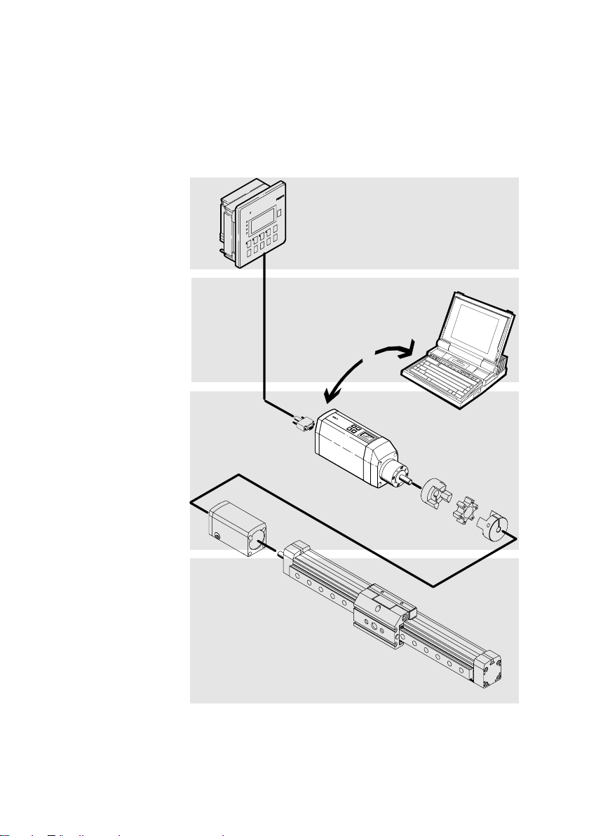
1
Higher−order
controller e.g.
Festo type FEC...
2 Software level:
Festo
Configuration
Tool
3 Motor/controller
level:
MTR−DCI +
coupling
4 Drive level e.g.
linear drive type
DMES−...
Components
1
2
3
1−4
4
Fig.1/1: Principle of an electric axis with the MTR−DCI−...
Festo P.BE−MTR−DCI−EN en 0411N H
Page 23
1. Summary of components
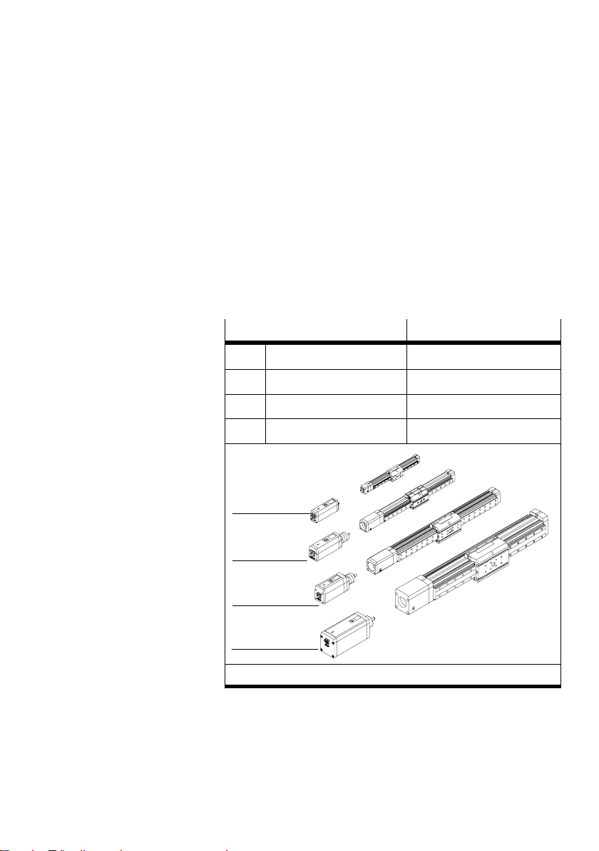
For setting up an electric axis you will require the following
components:
Motor unit MTR−DCI, optional with control panel
Linear drive e.g. servo drive in slide design with self−locking sliding thread
drive, guide: sliding or roll
er guide type DMES−... with acces
sories (see table Table1/1) and if applicable further compo
nents for the drive, e.g. a mechanical guide, coupling, coupl
ing housing etc.
Motor unit
1 MTR−DCI−32−...
2 MTR−DCI−42−...
3 MTR−DCI−52−...
4 MTR−DCI−62−...
2)
1)
1)
2)
Drive
DMES−18
DMES−25
DMES−40
DMES−63
1
2
3
4
1)
available
Table1/1: Axis variants with the DMES−...
2)
in preparation
Festo P.BE−MTR−DCI−EN en 0411NH
1−5
Page 24
1. Summary of components
Power unit for operating and load voltage supply.
MTR−DCI...−32/42/52: 24 V DC
MTR−DCI...−62: 48 V DC
Cable for transmission of information between higher−order con
troller, PC and MTR−DCI−... (see accessories).
nce switch optional: suitable sensor (normally−open) as reference switch
Refere
e.g. type SME−8/SMT−8 or SIEN−....
Gear reduction
High drive torques with low drive speeds are characteristic
for positioning functions. By means of two different gear re
ductions per unit size, different requests can be fulfilled with
the MTR−DCI in
(gear drive) speed. With the smaller gear reduction, the posi
tioning speed of the axis can be increased with correspon
dingly reduced positioning force.
respect of (gear drive torque) torque and
1−6
Size
Type MTR−DCI...G7, gear reduction 6.75:1
42 0.59 Nm 444 ±10% [1/min]
52 1.62 Nm 444 ±10% [1/min]
Type MTR−DCI...G14, gear reduction 13.73:1
42 1.13 Nm 218 ±10% [1/min]
52 3.08 Nm 218 ±10% [1/min]
Torque Speed
Table1/2: Gear reduction
Festo P.BE−MTR−DCI−EN en 0411N H
Page 25

1. Summary of components
Operating modes
Profile position mode Normal operation for positioning
Homing mode Positioning travel for referencing the mechanical reference
system.
For commissioning, for testing or for demonstration the fol
lowing functions are also available via the control panel
the MTR−DCI−...H2:
Positioning travel for ascertaining the target position of a
position set (Teach mode)
Positioning travel for testing all position sets in the posi
tion set table (Demo posit. tab.)
of
Positioning travel for
position set table (Move posit. set.)
testing a certain position set in the
Operational safety
An extensive system of sensors and monitoring functions
ensure operational safety:
Temperature monitoring (measuring the motor tempera
ture and the power end stage temperature)
Voltage monitoring
Recognizing faults in the internal
Recognizing overvoltages in the intermediate circuit
(only type MTR−DCI−62...)
Drag fault monitoring
Software end position recognition
voltage supply.
Festo P.BE−MTR−DCI−EN en 0411NH
1−7
Page 26

1. Summary of components
1.1.1 Method of operation
In the positioning mode, a certain position is specified to
which the motor is to move. The current position is obtained
from the information from the internal increment sensor (op
tical encoder). The position results
and the spindle pitch.
As the actual position is saved in a non−volatile memory in
the event of a power failure, a "quasi−absolute" position reg
istering can be implemented if a
The deviation of the position is processed in the position
controller and passed on to the speed regulator.
from the gear reduction
self−locking drive is used.
1 Motor controller
2 Controller
3 Nominal value
generator
4 Position
3
567
P
4
PI
P
controller
2
8
5 Speed regulator
6 Current regulator
1
7 End stage
8 Signal convertor
Fig.1/2: Simplified technical representation of the cascade regulator function
The motor unit takes over the following tasks:
specification of the nominal positions by positioning con
trol
comparison of the nominal and actual positions and posi
tion control
M
1−8
Festo P.BE−MTR−DCI−EN en 0411N H
Page 27

1. Summary of components
sequence control via digital inputs and outputs
The MTR−DCI possesses three memory ranges in which it
manages parameters:
The default settings and firmware are saved in the mem
ory (FLASH−Memory). The data
from the FLASH are
loaded when the device is switched on the first time or
when the EEPROM has been deleted.
The parameters which are currently used and which can
be modifie
d with the control panel or FCT software are
saved in the internal, volatile memory (RAM). When the
modifications have been saved, they are transferred to
the EEPROM.
The parameters which ar
e loaded after the device has
been switched on are saved in the non−volatile EEPROM.
The parameters in the EEPROM are retained even after
the power supply has been switched
off.
Please note
In order to restore the default settings you can, if necess
ary, delete the EEPROM via the serial interface with the CI
command 20F1 (Data memory control) (see chapter 7)
.
User−specific settings will then be lost.
· Use CI commands only if you already have experience of
Service Data Objects.
· If necessary consult the Festo Service.
The FLASH technology enables a firmware update (e.g. for
customer−specific firmware) to be loaded into the controller
via the RS 232 interface also at a
later stage. If necessary
consult the Festo Service.
Festo P.BE−MTR−DCI−EN en 0411NH
1−9
Page 28

1. Summary of components
1.1.2 Reference coordinates and working area
The measuring reference system of the MTR−DCI is based on
the axis zero point which is defined via the offset to the refer
ence point. The position of the referenc
the referencing method. The measuring reference system is
defined with homing. When the homing is finished, the drive
stands at the axis zero point. The working
DCI is defined by software end positions which refer to the
axis zero point.
Reference point REF forms the mechanical reference point of the axis coordinate
system and is
defined by homing with a reference switch or a
fixed stop, depending on the referencing method. It is the
basis point of the axis zero point.
e point is defined by
area of the MTR−
Axis zero point AZ is shifted by a d
efined distance from the reference point (axis
zero point offset) and is the basis point of the software end
positions and the project zero point. By defining the axis zero
point and the software end
positions you can limit the work
ing area of the linear axis to the permitted range (working
stroke).
Project zero point PZ is a basis point within the working stroke which the user can
select and to which both th
e actual position and the target
positions in the position set table refer. The axis zero point is
the basis point for the project zero point.
The project zero point is specified for the MTR−DCI
and is
identical to the axis zero point (project zero point offset = 0).
1−10
Festo P.BE−MTR−DCI−EN en 0411N H
Page 29
1. Summary of components
Reference coordinates and working area
Linear axis
1)
Rotation axis
2)
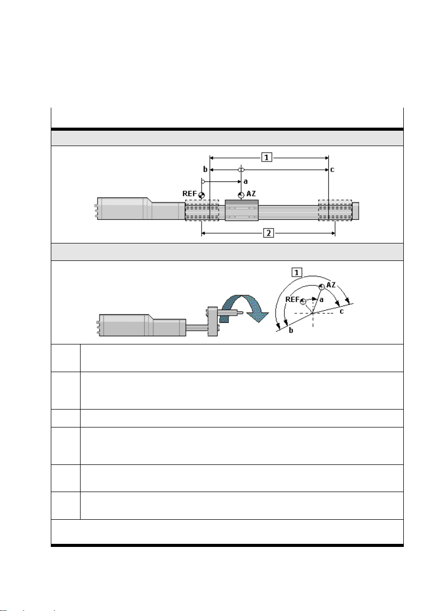
REF Reference point: The measuring reference point to which movement is made in the homing
and to which the axis zero point refers.
AZ Axis zero point: Measuring reference point for the project zero point and the software end
positions. Corresponds to the project zero point in the MTR−DCI (offset project zero point =
e basic point for the axis zero point is the reference point.
0). Th
a Offset axis zero point: Defined distance of the axis zero point to the reference point
b,c Software end positions: limit the permitted positioning range (working stroke). If the target
position of a positioning command lies outside the software end positions, the positioning
command will not be processed and a fault status will be display
ed.
1 Working stróke: Permitted positioning range. The working area of the axis is thereby de
fined.
2 Rated stroke: Rated stroke of the drive used, see Technical Specifications for the drive (with
DMES−... the stroke specified in the order).
1)
Vector representation for the referencing method: Fixed stop, negative
2)
Vector representation for the referencing method: Reference switch, negative
Table1/3:Measuring reference system of the electric axis
Festo P.BE−MTR−DCI−EN en 0411NH
1−11
Page 30

1. Summary of components
All position values (offset, software end positions, target
positions...) have a mathematical sign and must be adapted
to the position of the relevant reference point.
Value
+
1)
Linear axis Rotation axis
Positive values face from
the reference point in the
direction away from the
Positive angles face from
the reference point in a
clockwise direction.
2)
motor.
Negative values face from
the reference point in the
direction towards the
Negative angles face from
the reference point in an
anti−clockwise direction.
motor.
1)
Factory setting
2)
Angle measurements are specified viewed towards the motor
shaft.
All values are entered or displayed according to the measur
ing system set either for the FCT or the control panel.
Measuring system
1)
Linear axis
metric
inch
Rotation axis degree
3)
rev
2)
1)
Metric measuring units e.g.
mm, mm/s, mm/s
Imperial measuring units e.g.
inch, inch/s, inch/s
2
2
Angle measuring units in de
grees e.g. degree, degree/s,
degree/s
Revolutions
e.g. rev, rev/min, rev/min
2
2
1−12
1) Presetting for selecting the axis type on the control panel
2) Setting only with FCT when a project is started or via [Projekt]
[Properties].
3) Setting only with the control panel [Settings]
[Axis type] [Rotation
axis]
Festo P.BE−MTR−DCI−EN en 0411N H
Page 31

1. Summary of components
The setting of the measuring system on the control panel
influences only the display.
All the parameters in the controller are always saved in in
crements (inch, inch/s, inch/s
2 ... ) and are not converted
until they are written or read.
Measurements transmitted directly via the RS232 refer to an
increment basis (conversion see appendix B.3)
Festo P.BE−MTR−DCI−EN en 0411NH
1−13
Page 32

1. Summary of components
1.2 EMERGENCY STOP concept
Please note
Check within the framework of your EMERGENCY STOP
concept
to ascertain the measures necessary for putting your ma
chine / system into a safe state in the event
of an EMERGENCY ST
voltage)
Warning
Note that the MTR−DCI−...I/O does not have a separate
logic voltage supply. In the event of an EMERGE NCY STOP,
you should stop the drive by cancelling the ENABLE signal
at the I/O interfac
· Use additional separate safety limit switches if an
EMERGENCY STOP circuit is required for your applica
tion.
With these switches you can cancel the ENABLE sig
nal at the I/O interface
or switch off the ope
· By the arrangement of the limit switches and, if necess
ary, by additional appropriate mechanical stops, make
sure that the axis always lies within the permitted posi
tioning range.
OP (e.g. switching off the operating
e. (see chapter 6)
rating voltage.
1−14
Festo P.BE−MTR−DCI−EN en 0411N H
Page 33

1. Summary of components
1.3 Possibilities of commissioning
You can parametrize and commission the MTR−DCI as follows:
directly on the control panel (HMI, only type MTR−
DCI−...H2)
via the RS−232 interface (with FCT software)
The MTR−DCI can also be parametrized
and commissioned
with the Command Interpreter via the RS−232 interface. The
CI commands listed in the Object Directory can be trans
mitted to the MTR−DCI with all commercially−available ter
minal programs. O
nly experienced users may use the CI com
mands. Further information see chapter 7.
Functions
Parametrizing Selecting the axis type and the axis parameters
Specifying a gear factor (with external gears)
Uploading/downloading configuration data
Saving different configurations in projects
Position sets Compiling a position set table with set number,
target position, positioning mode, positioning
speed
Commissioning Homing
Moving in individual steps
Starting and stopping positioning procedures dur
ing commissioning
Extended test functions e.g. status dislpays
Testing or demonstrating the position sets
Diagnosis/Service Reading and displaying diagnostic data x x
HMI FCT
x
−
−
−
x x
x
−
x
−
x
x
x
x
x
x
x
x
x
x
Festo P.BE−MTR−DCI−EN en 0411NH
1−15
Page 34

1. Summary of components
1.3.1 Control panel (MTR−DCI−...−H2)
The control panel offers all functions necessary for commis
sioning, programming, diagnosing and operating directly on
the MTR−DCI− ...
The control panel provides the necessary input masks in
menus for editing position sets and paramete
tioning system is set up completely, you can move easily to
positions and transfer them to the position set table.
Information on the operating elements and the menu struc
ture can be
ing with the control panel as from chapter 5.2.2.
found in chapter 4, a description of commission
1.3.2Festo Configuration Tool (FCT)
The Festo Configuration Tool (or brief FCT) is the software
platform for configuring and commissioning different compo
nents or devices from Festo.
rs. If your posi
1−16
The FCT consists of the following components:
a framework as a program starting and entry
uniform project and data management for all supported
device types.
a PlugIn for the special demands of each device type (e.g.
MTR−DCI) with the necessary descriptions and dialogues.
PlugIns are managed and started from the frame
The
work.
The PlugIn MTR−DCI for the FCT supports all the steps necess
ary for commissioning an MTR−DCI.
The software can run on all usual PCs with a
operating system.
Festo P.BE−MTR−DCI−EN en 0411N H
point with
current Windows
Page 35
1. Summary of components
Minimum technical requirements
PC processor of the Pentium classe as from
Supported operating
systems
Run−time environment
+
software
Interface Serial interface <COMn> as per RS232,
Screen resolution Screen resolution as from 800 x 600 points,
900 MHz
128 MByte RAM
100 MByte free memory space on the
hard disc
Microsoft Windows® 2000 / XP
CD ROM for installation
Microsoft® .NET framework version
1.1, incl. necessary language package
(if required can be installed by the FCT
installation program)
Internet Explorer as from version 6.0
(necessary for the print
9600 baud
(for using the dynamic helps at least 1024 x
768)
functions)
An overview of commissioning with the FCT can be found in
chapter 5.2.1. The help for the FCT contains the complete
information on operating the Festo Configuration Tool. The
device−specific PlugIns each hav
e their own help files. You
can use the complete help or parts thereof irrespective of a
PC by printing them.
Festo P.BE−MTR−DCI−EN en 0411NH
1−17
Page 36

1. Summary of components
The FCT help system
The FCT offers various possibilities of obtaining information
or help with operation.
· Install and start the program as described in chapter 5
FCT help You can open the help for the FCT as follows:
· Access the help in the menu [Help] with the command
[Contents FCT general].
With function button F1 you can open directly a context−re
lated help.
Dynamic help For permanent display of conte
xt−related information you can
use the integrated dynamic help of the FCT:
· Activate the dynamic help via the menu [Help] with the
command [Dynamic help]. The dynamic hellp will be dis
played in a dockable window.
· Activate the element in the window for which you require
help, e.g. with a mouse click. If window areas or dia
logues of the PlugIn are activated, the contents of the
relevant PlugIn
will be dislpayed autmatically in the dy
namic help.
Help for PlugIn MTR−DCI The help for the PlugIn MTR−DCI contains the complete in
formation on operating the PlugIn.
You can open the help as follows:
· Command [Help] [Contents of installed PlugIns] [Festo
(manufacturer name)] [MTR−DCI (PlugIn name)].
· Help button in the window range or dialogue of the Plu
gIn.
· Button F1 in the active window range or dialogue of the
PlugIn.
1−18
Festo P.BE−MTR−DCI−EN en 0411N H
Page 37
1. Summary of components
Printed information In order to use the complete help or parts thereof indepen
dently of a PC, you can use one of the following possibilities:
· Use the "Print" button of the help window to print out
directly individual pages of the help or all the pages of a
book from the contents directory of the help.
· Print the prepared print version of the help in the Adobe
PDF or Rich Text format (RTF).
The relevant file can be found under the following indices:
Printed version
FCT help ...(FCT installation directory)\Help\ FCT_de.pdf
PlugIn help
(MTR−DCI)
Directory File
FCT_de.rtf
...(FCT installation directory)\HardwareFamilies\
Festo\MTR−DCI\V...\Help\
MTR−DCI_de.pdf
MTR−DCI_de.rtf
For using the print version in the Adobe PDF format you will
require the Adobe Reader.
Festo P.BE−MTR−DCI−EN en 0411NH
1−19
Page 38

1. Summary of components
1−20
Festo P.BE−MTR−DCI−EN en 0411N H
Page 39

Fitting
Chapter 2
Festo P.BE−MTR−DCI−EN en 0411NH
2−1
Page 40

2. Fitting
Contents
2. Fitting 2−1 . . . . . . . . . . . . . . . . . . . . . . . . . . . . . . . . . . . . . . . . . . . . . . . . . . . . . . . .
2.1 General instructions 2−3 . . . . . . . . . . . . . . . . . . . . . . . . . . . . . . . . . . . . . . .
2.2 Dimensions of the motor unit 2−4 . . . . . . . . . . . . . . . . . . . . . . . . . . . . . . . . . . . .
2.3 Fitting electric axes2−5 . . . . . . . . . . . . . . . . . . . . . . . . . . . . . . . . . . . . . . . . . .
. . . . . .
. . . .
.
2−2
Festo P.BE−MTR−DCI−EN en 0411NH
Page 41
2. Fitting
2.1 General instructions
Warning
· Make sure that the complete system is disconnected
from the electric power supply before you carry out work
on the system. Disconnect the system from the power
supply by means of the main switch
.
Please note
Handle all modules and components with great care.
Please note especially the following:
Screw connections must be fitted free of offset and
mechanical tension. Screws must be fitted accurately
(otherwise
threads will be damaged).
The specified torques must be observed.
The modules must not be offset.
Contact surfaces must be clean (avoid contact faults).
Festo P.BE−MTR−DCI−EN en 0411NH
2−3
Page 42
2. Fitting
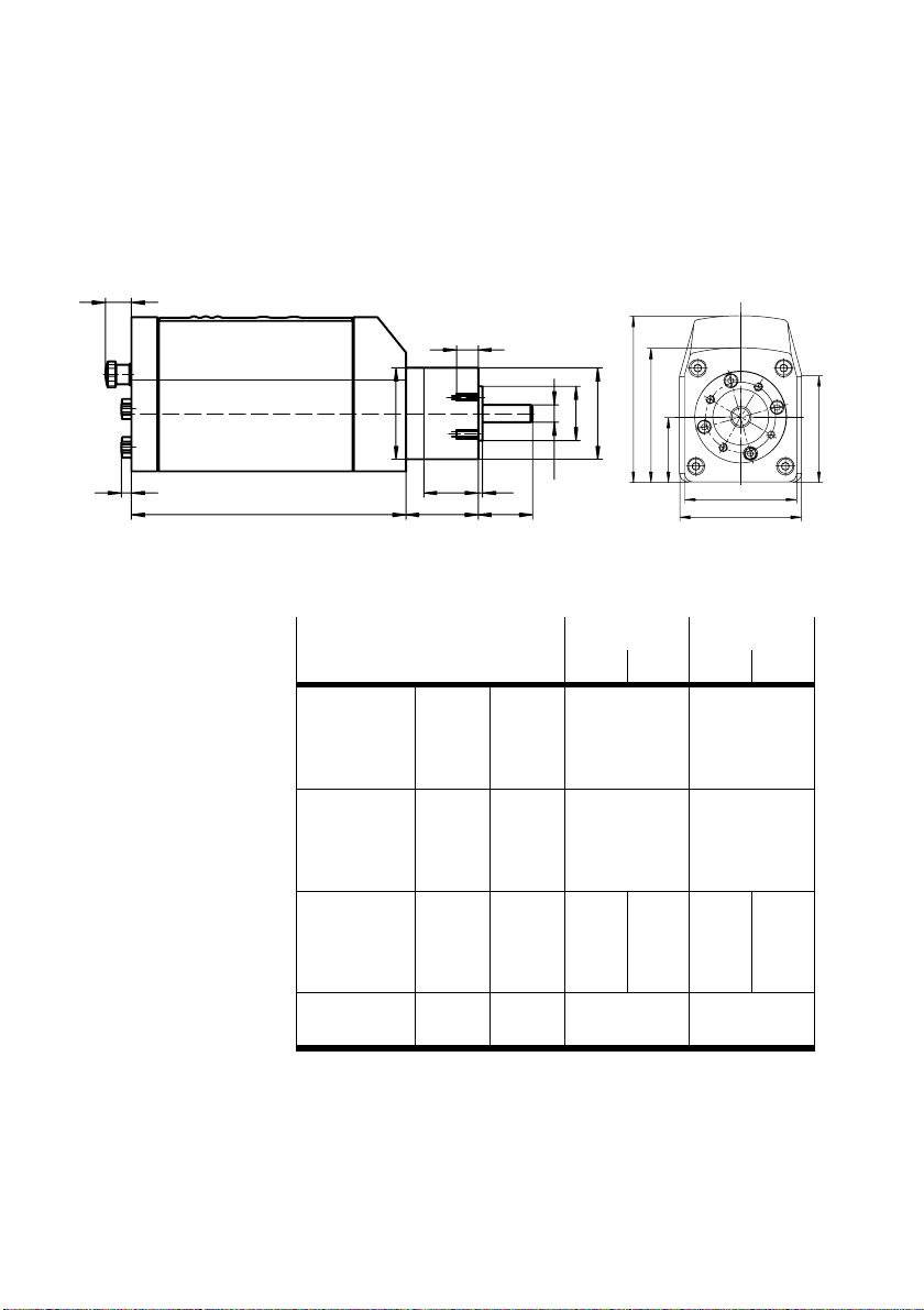
2.2 Dimensions of the motor unit
13
10
5
L1
Fig.2/1: Dimensions of the motor unit
Size
Gear ratio G7 G14 G7 G14
Diameter D [mm] D1
Height H [mm] H0
Length L [mm] L1
Width B [mm] B1
D2
L5
L4
L3
L2
H0
H2
D1
D3
D4
H1
B1
B2
H3
MTR−DCI−42 MTR−DCI−52
g10
D2
±0,1
D3
h8
D4
h7
±0,4
H1 ...
H2
±0,4
H3 ...
±1
L2
±1
L3
±1
L4 ...
±0.4
B2
±0.4
42
42
25
8
70,8
26,5
54,5
42,3
176
33,3
25
2
±0,2
44,8
53,3
±0,15
176
46,3
25
2
±0,2
52
52
32
12
94,8
37
76,5
60,7
194
39
33
3
±0,3
63,8
69,5
±0,2
194
53
33
3
±0,3
2−4
Festo P.BE−MTR−DCI−EN en 0411NH
Page 43

2. Fitting
2.3 Fitting electric axes
Refer to the following documentation when fitting the electric
axis:
Operating instructions for the electric linear axis used
Instructions for the components used
Warning
If an axis is fitted in a sloping or vertical position, the work
load may fall down and injure somebody.
· Check whether additional external safety measures are
necessary (e.g. toothed latches or moveable bolts).
· Use the motor unit preferably with self−locking spindle
drives.
You can then avoid the working mass sliding down if there
is a sudden power failure.
Festo P.BE−MTR−DCI−EN en 0411NH
Make sure that:
· the drive is fitted firmly and is free of tension on the
fastening flange
· the work space, in which the axis moves, is of sufficient
size for operation with a work load
· the work load does not collide with the motor or the gear
of the axis when the axis moves into the end position.
2−5
Page 44
2. Fitting
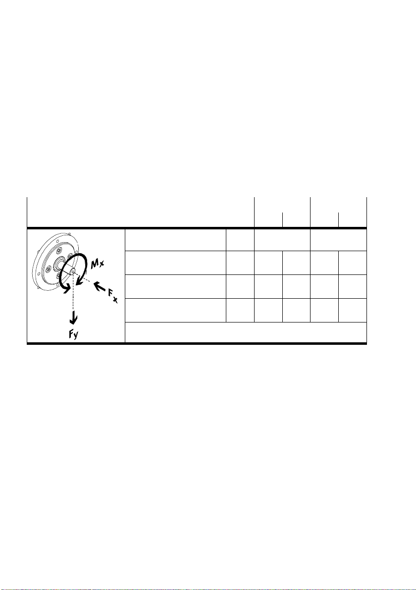
· Make sure that you observe the maximum permitted va
lues of the following variables:
axial force Fx
radial force F
drive torque M
y
x
Mechanical data * MTR−DCI−42 MTR−DCI−52
G7 G14 G7 G14
Flange [mm] 42 52
shaft loading radial F
shaft loading axial F
Torque Mx [Nm] 0,59 1,13 1,62 3,08
* The reference point for forces and torques is the centre of the shaft.
y
x
[N] 160 230 200 320
[N] 50 80 60 100
Table2/1: Maximum shaft loading and (gear drive) torques
2−6
Festo P.BE−MTR−DCI−EN en 0411NH
Page 45
2. Fitting
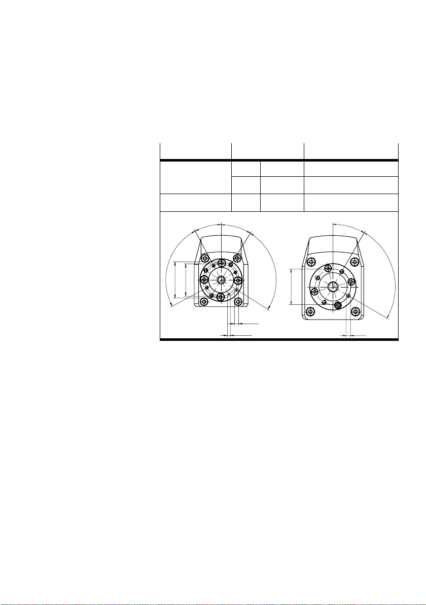
Use the 4 threads on the front of the gear for fastening the
drive.
Size
MTR−DCI−42−... M3 10 deep 1.2 Nm
MTR−DCI−52−... M5 10 deep 5.9 Nm
28°
4x
90°
32
36
@
@
Thread Tightening torque
M4 10 deep 2.9 Nm
32°
M4x10
M3x10
90°
4x
40
@
30°
M5x10
90°
4x
Table2/2: Fastening the drive by means of the front threads
(tightening torque)
· Position the drive with the aid of a centring diameter of
motor unit D1 or D3 (see fig. 2/1), in order to minimize
the shaft offset.
· Fasten the drive to the motor housing with the 4 fastening
screws and tighten the screws with the specified torque
(see Table2/2).
Festo P.BE−MTR−DCI−EN en 0411NH
2−7
Page 46
2. Fitting
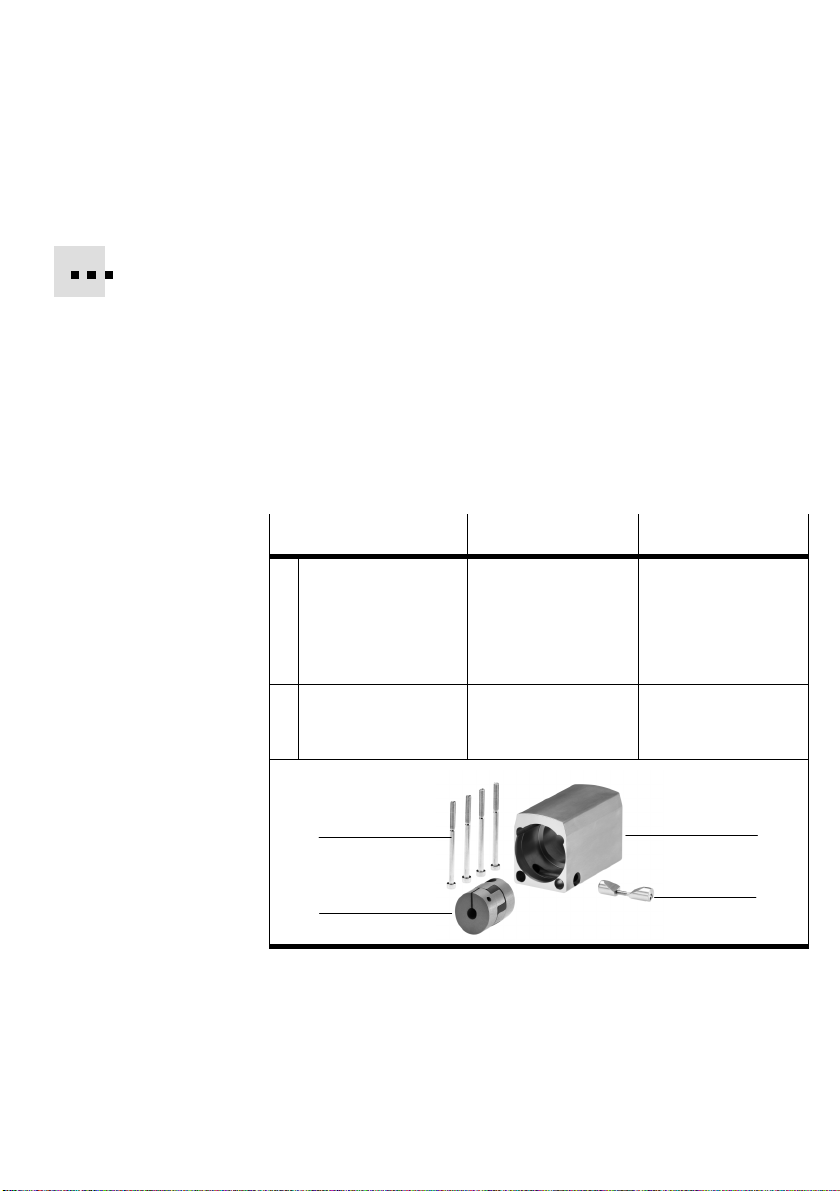
Fitting the coupling and coupling housing
Connecting elements (coupling, coupling housing, clamping
element) for axial fitting (e.g. for type DMES... or DGE...) are
available as accessories.
As an alternative to axial fitting, a corner gear is being
planned.
on all four sides of the drive (in preparation).
The motor unit is connected to the coupling housing by
means of a clamping device on the circumfere
housing. Additional motor flanges are not therefore necess
ary.
This will enable the motor unit to be fitted parallel
nce of the gear
Connecting element
1 Coupling Typ e
2
Coupling housing with
3
clamping element
4
4 fastening screws
4
1
MTR−DCI−42−... MTR−DCI−52−...
KSE−30−32−D06−D08
Clamping hub 1
Clamping hub 2
Typ e
DME−KG−25−...
Table2/3: Fitting accessories
(shaft @ 6 mm)
(shaft @ 8 mm)
Typ e
KSE−42−50−D12−D12
Clamping hub 1
(shaft @ 12mm)
Clamping hub 2
(shaft @ 12 mm)
Typ e
DME−KG−40−...
2
3
2−8
Festo P.BE−MTR−DCI−EN en 0411NH
Page 47
2. Fitting
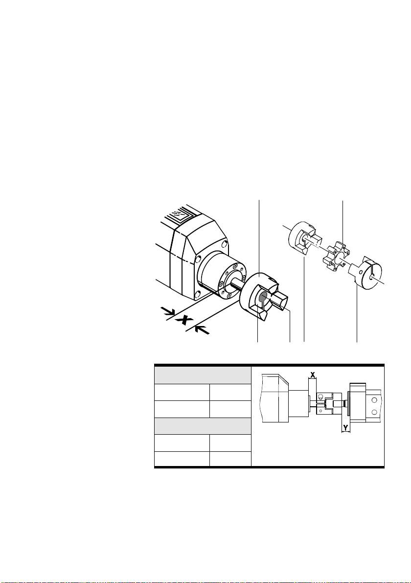
Fit first the clamping hubs of the coupling on motor unit MTR−
DCI and on nthe servo drive (type DMES...)
1. Press clamping hub 2 onto the drive shaft of the MTR−
DCI−... until the end of the drive shaft
inner surface.
Note the specified gap (x) between the clamping hub and
the motor unit (see Fig.2/2).
is flush with the hub
1 Clamping hub 1
of the coupling
2 Clamping hub 2
3 Drive shaft
4 Hub inner surface
5 Ring gear
Gap x [mm]
MTR−DCI−42 14,4
MTR−DCI−52 15,5
Gap y [mm]
DMES−25−... 8,3
DMES−40−... 16,5
Fig.2/2: Fitting the coupling type KSE−...
4
2
3
2
5
1
Festo P.BE−MTR−DCI−EN en 0411NH
2−9
Page 48

2. Fitting
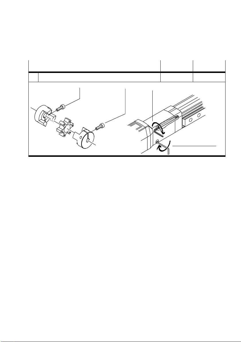
2. Grease the clamping hub slightly before tightening it. You
can then be sure that the clamping connection can easily
be loosened.
3. Tighten the greased clamping screw with the torque
specified (see
Table2/4). The screws must not protrude.
4. Press clamping hub 1 onto the drive shaft of the servo
drive until the end of the drive shaft is flush with the hub
inner surface.
Note the specified gap (y)
between the clamping hub and
the drive (see Fig.2/2).
5. Repeat steps 2 and 3 in order to fasten clamping hub 1 to
the servo drive.
6. Press the ring gear onto one of the clamping hubs.
the coupling housing type DME−KG...:
Fit
1. Fasten the coupling housing type DME−KG...
screws on the servo drive (tightening torque: see
Table2/4).
2. Press the clamping element into the hole in the side of the
coupling housing.
3. Press the motor with correctly placed clamping hub
the coupling housing (if necessary turn the motor).
4. Tighten the screw of the clamping element with the
torque specified (see Table2/4).
Tightening torque
Clamping screws of the hubs 4 Nm 8 Nm
1
Fastening screws of the coupling housing 2.9 Nm 5.9 Nm
2
2−10
MTR−DCI−42 MTR−DCI−52
Festo P.BE−MTR−DCI−EN en 0411NH
with all 4
into
Page 49
2. Fitting
Tightening torque MTR−DCI−52MTR−DCI−42
Screw of the clamping element 1.2 Nm 9.9 Nm
3
1
1
Table2/4: Fitting the coupling and the coupling housing
2
3
Festo P.BE−MTR−DCI−EN en 0411NH
2−11
Page 50

2. Fitting
2−12
Festo P.BE−MTR−DCI−EN en 0411NH
Page 51

Installation
Chapter 3
Festo P.BE−MTR−DCI−EN en 0411NH
3−1
Page 52

3. Installation
Contents
3. Installation 3−1 . . . . . . . . . . . . . . . . . . . . . . . . . . . . . . . . . . . . . . . . . . . . . . . . . . .
3.1 Overview of installation 3−3 . . . . . . . . . . . . . . . . . . . . . . . . . . . . . . . . . . . . . . . . . .
3.2 Power supply 3−6 . . . . . . . . . . . . . . . . . . . . . . . . . . . . . . . . . . . . . . . . . . . . . . . . . .
3.3 Serial interface3−8 . . . . . . . . . . . . . . . . . . . . . . . . . . . . . . . . . . . . . . . . .
3.4 Input for external reference switch 3−10 . . . . . . . . . . . . . . . . . . . . . . . . . . . . .
3.5 Connecting the higher−order controller 3−12 . . . . . . . . . . . . . . . . . . . . . . . . . . . . . .
. . . . . . . .
. . . .
3−2
Festo P.BE−MTR−DCI−EN en 0411NH
Page 53

3. Installation
3.1 Overview of installation
Warning
Before carrying out installation and maintenance work
always switch off the power supply for the electronic com
ponents.
You can thereby avoid:
unexpected movements of the connected actuators
non−defined switching states of
the electronic compo
nents.
Caution
Incorrectly prepared cables may damage the electronics
and trigger off unexpected movements of the motor.
· Use only the cables listed as accessories for connecting
the electric components of the system (see Table3/1).
Only in this way can you guarantee the correct function
ing of the system.
Please note
· Lay all moveable motor and sensor cables free of bends
and free of mechanical stress, if necessary, in a drag
chain.
· Observe the maximum specified cable lengths.
Festo P.BE−MTR−DCI−EN en 0411NH
3−3
Page 54
3. Installation
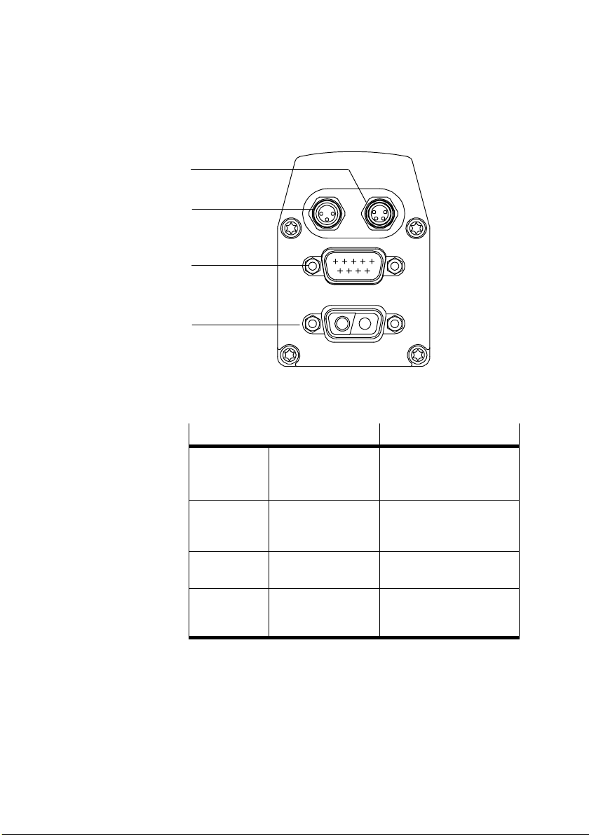
1 Power supply
2 Controller
3 Reference switch
4 Serial interface
4
3
2
1
Fig.3/1: Connections on the MTR−DCI
Connection on the MTR−DCI
Power supply DSub−9W2
Controller Sub−D 9−pin
Reference
switch
Plug
with type MTR−
DCI−IO..: Plug
M8, 3−pin
Socket
Description
Operating voltage connec
tion with high−current con
tacts
Interface for connecting
any PLC controller
Sensor input for reference
switch
3−4
Serial inter
face
M8, 4−pin
Socket
RS232 interface for
parametrizing, commis
sioning and diagnosing
Festo P.BE−MTR−DCI−EN en 0411NH
Page 55

3. Installation
If non−assigned plug connectors are touched, there is a
danger that damage may occur to the MTR−DCI or to other
parts of the system as a result of ESD (electrostatic dis
charge). Place protective
caps on unused connections in
order to prevent such discharges.
The plug connectors of the following Festo cables have been
designed so that, when inserted and screwed tight, or if fitted
protective covers, the connections on the MTR−DCI will
with
comply with protection class IP54. Appropriate protective
caps are included in delivery.
Connection
Power supply Supply cable KPWR−MC−1−SUB−9HC−... 2,5 / 5 / 10
Controller Control cable KES−MC−1−SUB−9HC−... 2,5 / 5 / 10
Reference switch e.g. type SME−8F−.../SMT−8F or extension cable type KM8−M8−...
Serial interface Programming cable KDI−MC−M8−SUB−9−... 2,5
Cable Designation Length [m]
Table3/1: Cables (accessories)
In order to guarantee compliance with the IP protection class:
· Tighten the union nuts/locking screws of the plugs by
hand.
· Seal unused connections with protective caps.
Warning
If the output pins are used incorrectly when a 24 V DC volt
age is applied, the device may be seriously damaged.
· Do not, therefore, connect voltage to the outputs.
· Note the current limitation at the outputs (see chapter
6.4)
Festo P.BE−MTR−DCI−EN en 0411NH
3−5
Page 56
3. Installation
3.2 Power supply
Warning
Use only power units which guarantee reliable electrical
isolation of the operating voltages as per EN 61558−2−6
(alternatively EN 60742) with at least 4 kV isolation resis
tance (Protected Extra Low Voltage PELV). Switch
power
packs are permitted, providing they guarantee reliable
isolation in accordance with EN 60950 / VDE 0805.
By the use of PELV power units, protection against electric
shock (protection against direct and indirect contact) is guar
eed in accordance with EN 60204−1 / IEC 204. Safety
ant
transformers with the adjacent symbol must be used for sup
plying PELV networks. The device must be earthed to ensure
that it functions correctly
(e.g. EMC).
The internal power and controller electronics are supplied
with DC voltage via the power supply connection.
3−6
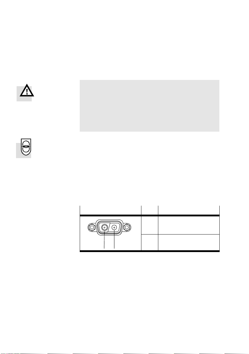
Plug
A1
A2
Pin Description
A1 +24 V DC
A2 GND
Table3/2: "Power supply" connection on the MTR−
DCI−42/52
Festo P.BE−MTR−DCI−EN en 0411NH
Page 57
3. Installation
The power supply must fulfil the following requirements:
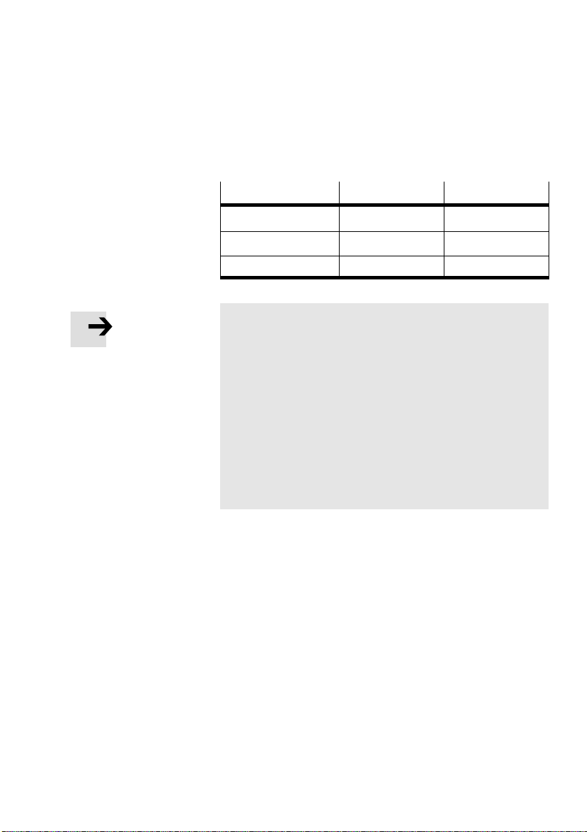
Title
Power supply 24 VDC ±10% 24 VDC ±10%
Rated current (motor) 2 A ± 20% 5.1 A ± 20%
Peak current 3.8 A 7 A
MTR−DCI−42 MTR−DCI−52
Please note
Note that the tolerance for the supply voltage must be
observed. The tolerance must be observed directly at the
operating voltage connection of the MTR−DCI.
· Use cables of sufficient diameter and of sufficient length
for the power supply:
Connecting cable KPWR−MC−1...
Cable length max. 10 m.
· Use a closed−loop power unit with:
24 VDC / 6 A for MTR−DCI− 42−...
24 VDC / 10 A for MTR−DCI− 52−...
Festo P.BE−MTR−DCI−EN en 0411NH
3−7
Page 58

3. Installation
3.3 Serial interface
Serial interface for parametrizing, commissioning and diag
nosing
Warning
If the input pin (pin 4) is used incorrectly when a 24 V DC
voltage is applied, the device may be seriously damaged.
The input (pin 4) is intended exclusively for authorized
Festo service
· Do not, therefore, apply voltage to pin 4.
· Use only the programming cable from Festo.
· If necessary, remove the protective cap from the serial
personnel.
interface of the MTR−DCI.
· Connect the following connections with the programming
cable:
3−8
the connection socket on the MTR−DCI
a serial interface COMx of the diagnostic PC.
M8 socket
1 243
1)
The levels correspond to the RS232 standard and enable a data
transmission rate of 9600 Baud
Description
1 GND Ground
2 TXD RS232 transmitting cable
3 RXD RS232 receiving cable
4 −−− reserved − do not connect
Table3/3:Serial interface on the MTR−DCI
Festo P.BE−MTR−DCI−EN en 0411NH
1)
1)
Page 59

3. Installation
Information on commissioning and parametrizing the MTR−
DCI via the serial interface can be found in chapter 5.2.1 and
in the help system for the FCT software package.
Information on transmitting CI commands via the serial
inter
face can be found in chapter 7.
Please note
The RS232 interface is not electrically isolated. It is not
suitable for permanent connection to PC systems, nor as a
control interface.
· Use this connection only for commissioning.
· Do not exceed the maximum permitted signal cable
length of 2.5 m.
· Disconnect the diagnostic cable during continuous oper
ation.
· Seal the connection with the protective cap supplied
(type ISK−M8).
Festo P.BE−MTR−DCI−EN en 0411NH
3−9
Page 60

3. Installation
3.4 Input for external reference switch
If you are not using a reference switch:
· Seal the connection with the protective cap supplied (type
ISK−M8).
Connecting the reference switch:
· Use the correct switch type "normally−open" for the refer
ence switch.
· For connecting the reference switch use a cable with rotat
ing thread sleeve on the end of the cable e.g. type
SME−8F−.../SMT−8F or extension cable type KM8−M8−...
· When selecting the sensor, note that the accuracy of the
switchover point of the sensor determines the accuracy of
the reference point.
Use e.g. the following proximity switches from Festo:
3−10
ele
ctric proximity switch SME−8 /SMT−8 (can be fitted in
the sensor groove of the drive profile).
Switching accuracy:
SME−8: 0.2 mm (±0.1 mm)
SMT−8: 0.4 mm (±0.2 mm).
inductive proximity switch SIEN−..−M8 (can be used in
slide design in
conjunction with switching lug SF/support
angle HWS);
Switching accuracy: 0,08 mm.
Festo P.BE−MTR−DCI−EN en 0411NH
Page 61
3. Installation
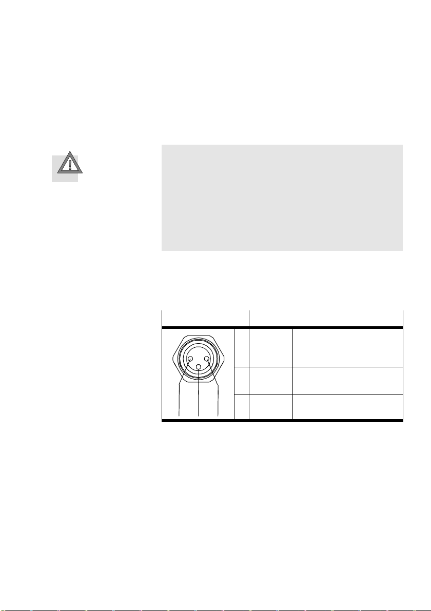
The power supply for the reference switch (24 V DC / Ground)
is provided via pin 1/3.
Caution
Damage to the device
The 24 V DC voltage at pin 1 does not have any special
protection against overload; the voltage is taken from the
main supply after the ESD and protection against incorrect
polarity.
· Use this connection only for the reference switch. Use of
this connection as power supply is not permitted.
The input for sensor signal REF complies in its electrical fea
tures with the input spe
cification in the appendix "Technical
specifications."
Festo P.BE−MTR−DCI−EN en 0411NH
M8 socket
143
Description
1 + 24 V DC + 24 V DC voltage output for
reference switch
4 REF Contact reference switch
3 GND Ground
Table3/4: "Reference switch" connection on the MTR−DCI
3−11
Page 62

3. Installation
3.5 Connecting the higher−order controller
Information on controlling via bus systems can be found in
the manuals for the relevant field bus variant of the MTR−
DCI−... (in preparation).
In the case of control via digital I/Os (type MTR−DCI−IO...) note
th
e instructions on connecting and on the function of the I/O
interface in chapter 6.
3−12
Festo P.BE−MTR−DCI−EN en 0411NH
Page 63

Control panel (MTR−DCI−...−H2−IO)
Chapter 4
Festo P.BE−MTR−DCI−EN en 0411NH
4−1
Page 64

4. Control panel (MTR−DCI−...−H2−IO)
Contents
4. Control panel (MTR−DCI−...−H2−IO) 4−1 . . . . . . . . . . . . . . . . . . . . . . . . . . . . . . . .
4.1 Composition and function of the control panel 4−4 . . . . . .
4.2The menu system4−6 . . . . . . . . . . . . . . . . . . . . . . . . . . .
4.2.1 Accessing the main menu 4−6 . . . . . . . . . . . . . . . . . . . . .
4.2.2"Diagnostic" menu 4−8 . . . . . . . . . . . . . . . . . . . . . . . . . . . . . . . . .
4.2.3 Device control "HMI control" 4−10 . . . . . . . . . . . . . . . . . . . . . . . . . . . . . .
4.2.4"Settings" menu 4−11
4.2.5 "Positioning" menu 4−17 . . . . .
. . . . . . . . . . . . . . . . . . . . . . . . . . . . . . . . . . . . . . . .
. . . . . . . . . . . . . . . . . . . . . . . . . . . . . . . . .
. . . . . . . . . . . . . . . . . . . .
. . . . . . . . . . . . . . . . .
. . . . . . . . . . . .
. . . . .
4−2
Festo P.BE−MTR−DCI−EN en 0411NH
Page 65
4. Control panel (MTR−DCI−...−H2−IO)
Motor unit type MTR−DCI−...H2 offers on the control panel all
functions necessary for commissioning, programming and
diagnosing − ... An overview of the button and menu functions
for the MTR−DCI−IO can be found in this chapter.
ing with the control panel is described as from chapter 5.2.2.
Control panel functions for the field bus variants can be found
in the manual for the relevant product variant.
Commission
With the MTR−DCI−...H1 (without
control panel) you can com
mission the MTR−DCI via the RS−232 interface (with FCT soft
ware). Instructions on this can be found in chapter 5.2.1.
Caution
Faults may occur if you attempt to access control and oper
ating functions at the same time by the FCT and the control
panel.
· Make sure that the FCT, the control panel and the control
interface of the MTR−DCI are not used at the same time.
Please note
If necessary, remove the protective foil from the display
before commissioning.
Festo P.BE−MTR−DCI−EN en 0411NH
4−3
Page 66
4. Control panel (MTR−DCI−...−H2−IO)
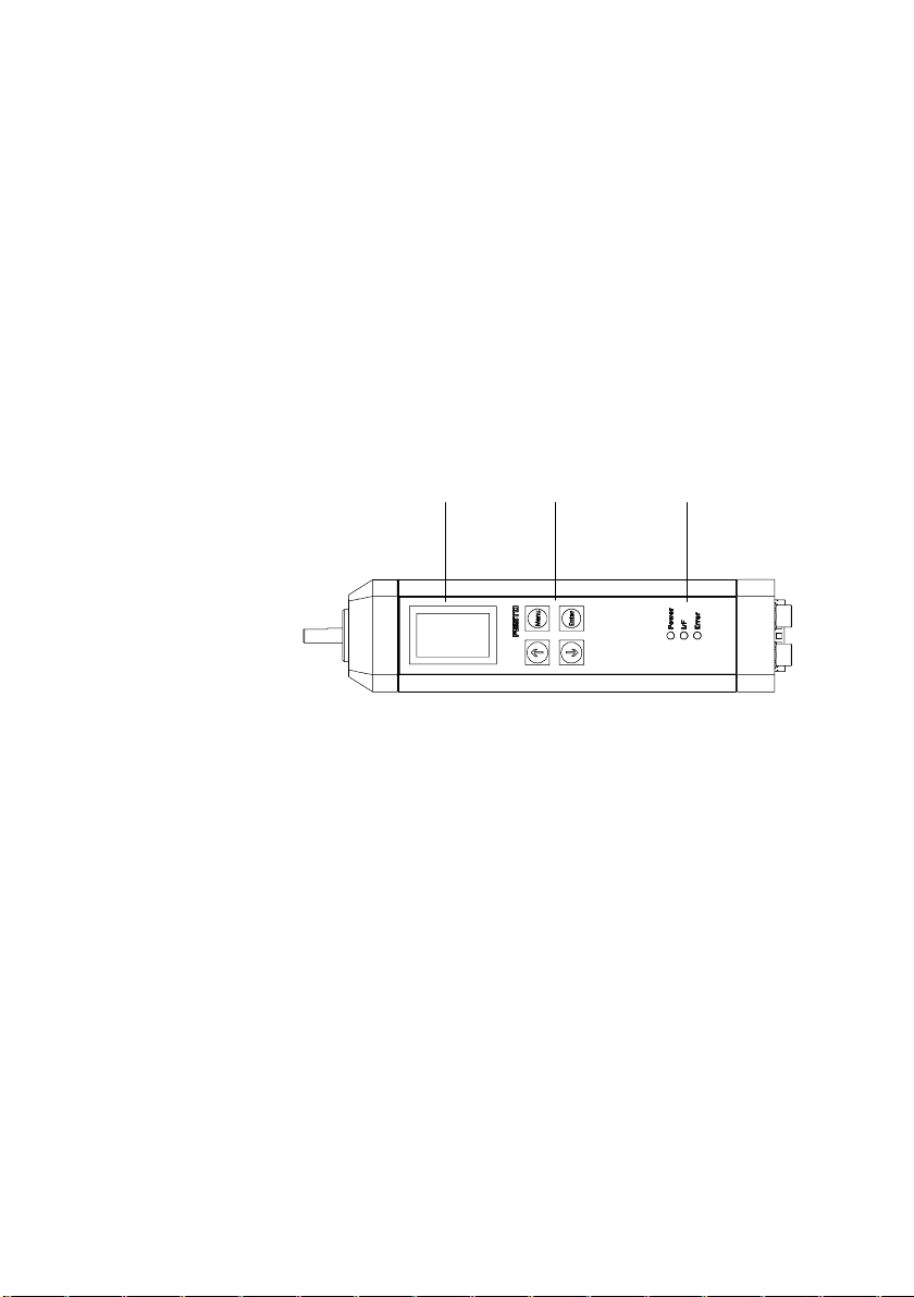
4.1 Composition and function of the control panel
The control panel enables commissioning directly on the
MTR−DCI with the following functions:
Parametrizing and referencing the axis
Entering positioning sets
Test functions e.g. for moving to individual position sets.
1 LC display
2 Operating
buttons
3 LEDs
power (green)
I/F (green/red)
Error (red)
1
Fig.4/2: Control panel of the MTR−DCI−...−H2
With the 4 buttons on the control panel you can carry out all
operating functions and settings as indicated in the menu.
The graphic LCD display shows all texts in English
can be turned in 90° steps, see menu command [LCD adjust
ment].
The visual display of the operating states is shown via 3 LEDs
(see also chapter 5.7.2).
Power: Display of the readiness
I/F: Positioning status
Error: Faults
2
to operate
3
. The display
4−4
Festo P.BE−MTR−DCI−EN en 0411NH
Page 67
4. Control panel (MTR−DCI−...−H2−IO)
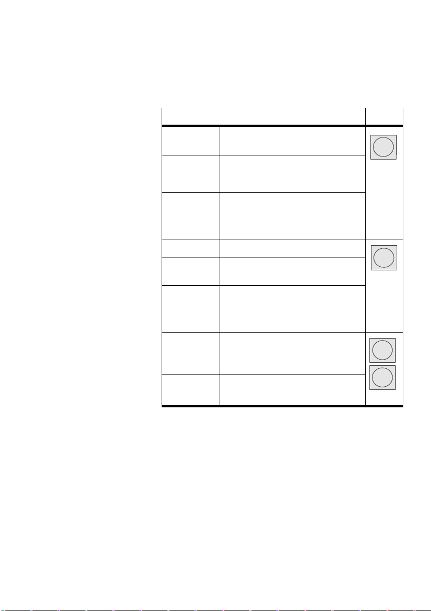
Function Button
MENU activated by the status display from the
main menu Menu
ESC rejects the current entry and switches
back in stages to the higher−order menu
level or status display
EMERG.STOP interrupts the current positioning proce
dure (> Error mode; confirm with <En
ter>, then automatic return to the status
display)
OK confirms the current selection or entry
SAVE saves parameter settings permanently
in the EEPROM
START/STOP starts or stops (demo mode only) a po
sitioning procedure. After stop: Display
of the current position, with <Menu> re
turn to the higher−order menu level.
<− −> scrolls within a menu level in order to
select a menu command.
EDIT sets the parameter
Table4/1: Button function (overview)
Enter
v
V
Festo P.BE−MTR−DCI−EN en 0411NH
4−5
Page 68

4. Control panel (MTR−DCI−...−H2−IO)
4.2 The menu system
4.2.1 Accessing the main menu
MTR–DCI...
Xa = 0.00 mm
HMI:off
<Menu>
} Diagnostic
positioning
Settings
S ESC <Menu>
<––> OK <Enter>
} HMI control
LCD adjustment
S ESC <Menu>
<––> OK <Enter>
When the power supply is switched on, the MTR−DCI auto
matically carries out an internal check. At first the display
shows the Festo Logo then changes to the status display. The
status display shows the following information:
e type designation of your MTR−DCI
th
the current position of the drive x
= ....
a
the current setting of the device control (HMI = Human
Machine Interface)
The main menu is accessed from the status display with the
button <Menu>. The current button function will be displayed
in the lower lines of the LCD display.
Function
<− −> With the arrow buttons on the control panel
you can select a menu item from the list. The
current selection is marked with an arrow ( }
Diagnostic). Select the menu item S in order
to display further menu items (HMI control...).
ESC With <Menu> you can interrupt the current entry
and return in stages to the higher−order menu
level or status display.
OK With<Enter> you can confirm the current selec
tion or entry.
Button
v
V
Menu
Enter
4−6
Table4/2: Button function (menu selection)
Festo P.BE−MTR−DCI−EN en 0411NH
Page 69
4. Control panel (MTR−DCI−...−H2−IO)
} yp
} p
}
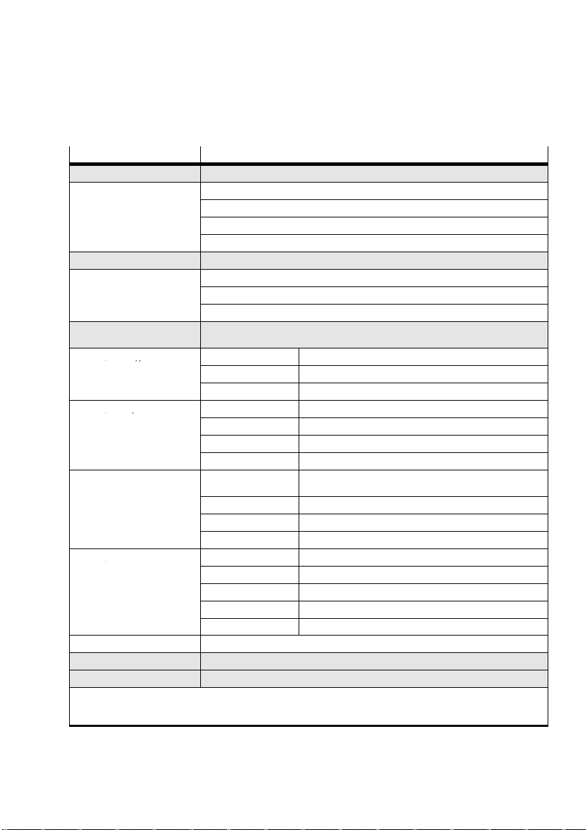
Menu commands Description
} Diagnostic Display of the system data and the currently effective settings (see chapter 4.2.2)
} Pos.set table Display of the position set table
} Axis param Display of axis parameters and data
} System param Display of system parameters and data
} SW information Display of the operating system version (firmware)
1) 2)
1) 2)
1)
Homing and positioning travel for testing the position sets (see chapter 4.2.5)
Selection of the drive, parametrizing, programming the position sets ... (see chapter
4.2.4)
} Rotation drive Rotation axis with stop
} User config Any linear drive
3)
} Abs.min.pos
} Abs.max.pos
Offset of axis zero point
3)
Stroke limitation: Software end position, negative
3)
Stroke limitation: Software end position, positive
} Save... Save parameter in EEPROM
switch...)
} Velocity v_sw Positioning speed for searching for the reference point
} Velocity v_s0 Positioning speed for moving to the axis zero point
} Save... Save parameter in EEPROM
} Pos set mode Record status: absolute or relative positioning
} Position
3)
Target position of the position set
} Velocity Positioning speed of the position set
} Save... Save parameter in EEPROM
Presetting the device control via the control panel (see chapter 4.2.3)
} Positioning
} Move pos. set Star t positioning travel "Position set"
} Demo pos. table Start positioning travel "Position set table"
} Homing Star t homing
} Settings
} Axis type } Typ e DMES−... Festo linear axis with servo drive type DMES−..
} Axis param } Zero point
} Homing param } Homing method Selection of referencing (homing) method (stop, software limit
} Position set } Position no. Number of the position record (0..14)
} Password Setting up a local password with 3 figures for the control panel (see chapter 4.2.4).
} HMI control
} LCD adjustment Turning the display in 90° degree steps
1)
if necessary password protection
2)
Control interface must be deactivated, see [H MI control]:HMI=on
3)
Teach mode
Table4/3:Menu commands (overview)
Festo P.BE−MTR−DCI−EN en 0411NH
4−7
Page 70
4. Control panel (MTR−DCI−...−H2−IO)
4.2.2"Diagnostic" menu
In order to display the system data and the currently effective
settings:
} Diagnostic
1. Use the arrow buttons in the main menu to select [Diag
nostic] and press the <Enter>button.
} Pos.set table
Axis param
System param
Software information
2. Select one of the
Position set table
following menu commands:
Axis parameter [Axis param]
System parameter [System param]
Version of firmware of the MTR−DCI e.g. V−DME 1.19
[Software information]
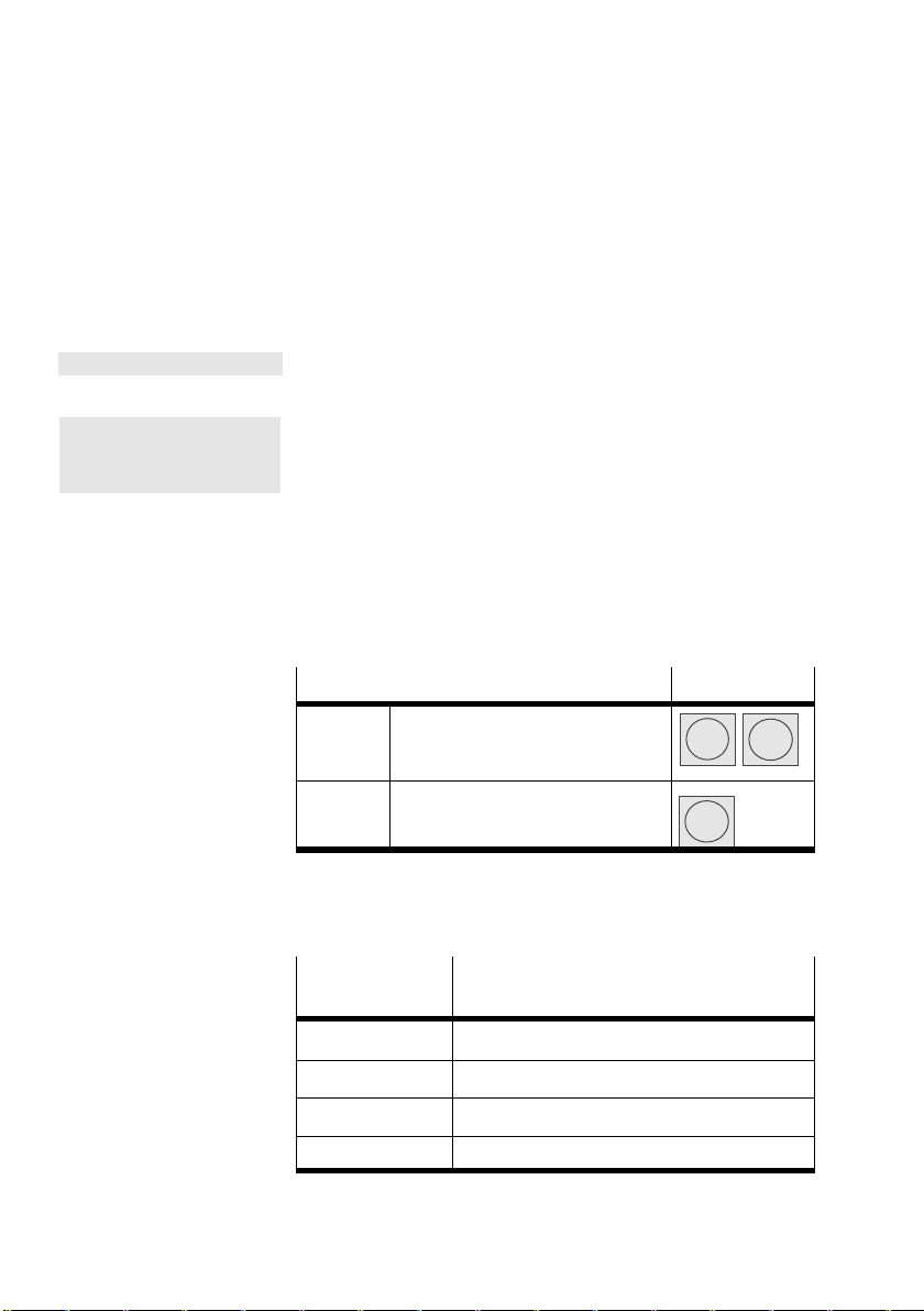
Function
<− −> Yo u can "scroll through" the dia
gnostic data with the arrow but
tons.
ESC With <Menu> you can return to the
higher−order menu level.
Button
v
Menu
V
[Pos. set .table]Menu command for displaying the following entries in the
position set table:
[Position set ta
Description
ble]
4−8
no. Number of the position set (0..14)
a/r absolute (a) or relative (r) positioning
Pos Target position
Vel Positioning speed
Festo P.BE−MTR−DCI−EN en 0411NH
Page 71

4. Control panel (MTR−DCI−...−H2−IO)
[Axis param] Menu command for displaying the following axis parameters
and data:
[Axis param]
v max Maximum positioning speed
x min Stroke limitation: Software end position, nega
x max Stroke limitation: Software end position, posi
x 0 Offset axis zero point
2)
feed
1)
Measuring unit depends on measuring system set
2)
not for axis type "Rotation drive"
1)
Description
tive
tive
Feed constant (e.g. thread pitch)
[System param] Menu command for displaying the following system para
meters and data:
[System param]
V power [V] Power supply
V dd [V] Voltage for display
I max [A] Maximum current
I act [A] Current current
Temp [°C] Operating temperature
Description
Festo P.BE−MTR−DCI−EN en 0411NH
Cycle Number of positioning cycles
In−signal hexadecimal representation of the inputs
Bit 0: E0
Bit 1: E1
Bit 2: E2
Bit 3: E3
Bit 4: START
Bit 5: ENABLE
4−9
Page 72

4. Control panel (MTR−DCI−...−H2−IO)
[System param] Description
Out−signal hexadecimal representation of the outputs
Ref. switch on/off Signal at reference switch input
Mode e.g. mm Measuring system
Hom.meth. bl.pos
Gear e.g. 6.75 Gear ratio of the MTR−DCI
Bit 0: READY
Bit 1: MOTION COMPLETE
bl.neg
sw.pos
sw.neg
Fixed stop in positive direction
Fixed stop in negative direction
Reference switch in positive direction
Reference switch in negative direction
4.2.3 Device control "HMI control"
For selecting the menu commands [Positioning] and [Settings]
you will require the setting "HMI on." Only then is the MTR−
DCI ready to process user entries on the control panel.
electing the menu commands, you will be requested
When s
to modify the HMI setting.
[HMI control] You can also modify the setting directly with the menu com
mand [HMI control].
1)
HMI
Device control
4−10
on The device control is carried out manually via the control
off The device control is carried out via the control interface
1)
panel. The control interface of the MTR−DCI is deactivated
and the control enable is set. The actual status of the
ENABLE input then has no effect.
of the MTR−DCI.
Human Machine Interface
Festo P.BE−MTR−DCI−EN en 0411NH
Page 73

4. Control panel (MTR−DCI−...−H2−IO)
4.2.4"Settings" menu
For parametrizing the axis system and programming the posi
tion sets:
} Settings
1. Use the arrow buttons to select [Settings] in the main
menu and press the <Enter>button.
} Axis type
Axis param
Homing param
Position set
Password
2. Select:
the axis type [Axis type]
the axis parame
ters [Axis param]
the referencing parameters [Homing param]
the position set table [Position set]
the password setting [Password]
[Axis type] Design of axis driven by the MTR−DCI.
[Axis type]
[Type DMES−...] Festo linear axis with servo drive type DMES−...
[Rotation drive] Rotation axis
Parameters
The selection defines the following settings:
the feed constant e.g.
MTR−DCI 42 + DMES−25: 2.5 mm / spindle revolution
MTR−DCI 42 + DMES−40: 4 mm / spindle revolution
the measuring system (metric)
The following setting is necessary:
Measuring system in degrees or revolutions (degrees /revolutions)
[User config] Any linear drive
The selection defines the following settings:
the measuring system (metric)
The following setting is necessary:
the feed constant (Feedcon) in mm per revolution of the axis drive shaft (see
type plate or technical data for the drive).
Festo P.BE−MTR−DCI−EN en 0411NH
4−11
Page 74
4. Control panel (MTR−DCI−...−H2−IO)
[Axis param] Teach mode for setting the axis parameters
Warning
During the teach procedure for specifying the axis zero
point and the stroke limitation, the motor turns or the con
nected axis starts to move.
· Make sure that nobody can place his/her hand in the
positioning range of the moveable mass and that no
objects lie in its path.
[Axis param]
[Zero point] Offset of axis zero point
[Abs.min.pos] Stroke limitation: Software limit switch, nega
[Abs.max.pos] Stroke limitation: Software limit switch, posi
[Save...] Save parameter in EEPROM
Description
tive
tive
Please note
The set parameters become effective immediately after
confirmation with OK <ENTER>. The settings are saved per
manently in EEPROM with the menu command [Save...]:
· Save the parameter settings with the menu command
[Save]. Only then will the settings be retained even if the
power supply is switched off or if there is a power fail
ure.
4−12
Festo P.BE−MTR−DCI−EN en 0411NH
Page 75
4. Control panel (MTR−DCI−...−H2−IO)
[Homing param] Setting the referencing method and the speeds during hom
ing.
The maximum speed during homing is limited to half the
maximum positioning speed v_max (v_max see [Diagnostics]
[Axis param] ).
[Hom. param]
[Homing method] sw.neg
[Velocity v_sw] v_sw Speed for searching for
[Velocity v_s0] v_s0 Speed for moving to the
[Save...] Save parameter in EEPROM
Param. Description
(switch negative)
sw.pos
(switch positive)
bl.neg
(block negative)
bl.pos
(block positive)
Homing to reference
switch, negative
= factory setting
Homing to reference
switch, positive
Homing to fixed stop, ne
gative
Homing to
fixed stop, positive
the reference point
axis zero point
Please note
The set parameters become effective immediately after
confirmation with OK <ENTER>. The settings are saved per
manently in EEPROM with the menu command [Save...]:
· Save the parameter settings with the menu command
[Save]. Only then will the settings be retained even if the
power supply is switched off or if there is a power fail
ure.
Festo P.BE−MTR−DCI−EN en 0411NH
4−13
Page 76
4. Control panel (MTR−DCI−...−H2−IO)
[Position set] Teach mode for programming the position set table.
Warning
During the teach procedure for specifying the target posi
tion, the motor turns or the connected axis starts to move.
· Make sure that nobody can place his/her hand in the
positioning range of the moveable mass and that no
objects lie in its path.
[Position set]
[Position no.] no. Number of the position set [0..14]
[Pos set mode] [absolu
[Position] xt Target position in the selected
[Velocity] v Positioning speed in the selected
[Save...] Save parameter in EEPROM
Param. Description
te/rela
tive]
Positioning mode
absolute = absolute position spe
cification, related to the project
zero point
relative = relative position specifi
cation, related to the current posi
tion
measuring system e.g. [mm]
measuring system e.g. [mm/s]
Please note
The set parameters become effective immediately after
confirmation with OK <ENTER>. The settings are saved per
manently in EEPROM with the menu command [Save...]:
· Save the parameter settings with [Save]. Only then will
the settings be retained even if the power supply is
switched off or if there is a power failure.
4−14
Festo P.BE−MTR−DCI−EN en 0411NH
Page 77

4. Control panel (MTR−DCI−...−H2−IO)
In order to prevent unauthorized or unintentional overwriting
or modification of parameters in the device, access via the
control panel can be protected by a (local) password. No
password is specified at the
factory (presetting 000).
Set up a password
[Password] Select [Settings] [Password] in the menu.
New Password:
[?xx] =
ESC <Menu>
EDIT <––> OK <Enter>
Enter a password with 3 figures. The current entry position is
marked with a question mark.
1. Use the arrow buttons to select a figure 0..9
Enter password:
[?xx] =
ESC <Menu>
EDIT <––> OK <Enter>
2.Confirm your entrry with
<Enter>. The next entry position
will be displayed.
3. After entering the third figure, save your setting with
SAVE <Enter>.
Enter password
As soon as a password is active, it will be automatically
scanned when the menu commands [Positioning], [Settings]
or [HM I control] are accessed. When the correct password is
entered, all parametrzing and control functions of th
panel are enabled until the power supply is switched off.
The current entry position is marked with a question mark.
1. Use the arrow buttons to select a figure 0..9.
2.Confirm your entry with <Enter>
. The next entry position
will be displayed.
3. Repeat the entry for the further entry positions.
When the third figure has been entered, access via the con
trol panel is enabled.
e control
Festo P.BE−MTR−DCI−EN en 0411NH
4−15
Page 78

4. Control panel (MTR−DCI−...−H2−IO)
Modify/deactivate password
[Password] Select [Settings] [Password] in the menu:
Enter password:
[?xx] =
ESC <Menu>
EDIT <––> OK <Enter>
Enter the existing password with 3 figures. The current entry
position is marked with a question mark.
1. Use the arrow buttons to select a figure 0..9
New Password:
[?xx] =
ESC <Menu>
EDIT <––> OK <Enter>
2.Confirm your entry
with OK<Enter>. The next entry position
will be displayed.
3. Repeat the entry for the further entry positions.
4. Enter the new password with 3 figures. If you wish to
deactivate the password, enter
"000."
5. After entering the third figure, save your setting with
SAVE <Enter>.
· Keep the password for the MTR−DCI in a safe place, e.g. in
the internal documentation for your system.
If the active password in the MTR−DCI should be lost in spite
of care being taken:
can delete it by entering a master password. In this case
you
please contact your Festo Service partner.
4−16
Festo P.BE−MTR−DCI−EN en 0411NH
Page 79
4. Control panel (MTR−DCI−...−H2−IO)
4.2.5 "Positioning" menu
Start homing or positioning travel for testing the position
sets.
Please note
· Make sure before star ting homing that:
the positioning system is set up completely, wired
the parametrizing is completed.
· Do not start positioning travel until the reference system
has been defined by homing.
Warning
Danger of injury
With all positioning procedures the motor turns or the con
nected axis starts to move.
· Make sure that nobody can place his/her hand in the
positioning range of the moveable mass and that no
objects lie in its path.
and supplied with power.
Festo P.BE−MTR−DCI−EN en 0411NH
Please note
Please note that position sets with speed v = 0 or invalid
target positions ( −> Fault "TARGET POSITION OUT OF
LIMIT) cannot be processed.
4−17
Page 80
4. Control panel (MTR−DCI−...−H2−IO)
Carry out homing
} Positioning
1. Use the arrow buttons to select [Positioning] in the main
menu and press the <Enter>button.
Move posit set
Demo pos table
} Homing
[Positioning]
[Homing] Homing for determining the mechani
...
Warning Motor moves
2. Select the menu command:
Homing [Homing]
Description Please note
cal reference system
3. Make sure that nobody can place his/her hand in the
positioning range of the moveable mass and that no ob
jects lie in its path. Start homing with START <Enter>
ESC <Menu>
START <Enter>
HOMING
V0 = 20 mm/s
v_sw = 10 mm/s
EMERG.STOP<Menu>
The following information is displayed:
the search speed v_sw
the positioning speed to the axis zero point v_0.
Function
First set the parameter in the menu
[Settings] [Homing parameter].
Factory setting: Homing to stop in ne
gative direction
4−18
EMERG
.STOP
With<Menu> you can interrupt the positioning
procedure (> Error mode EMERG.STOP; con
firm with <Enter>, then automatic return to the
status display).
Festo P.BE−MTR−DCI−EN en 0411NH
Menu
Page 81

4. Control panel (MTR−DCI−...−H2−IO)
Carry out position sets
} Positioning
1. Use the arrow buttons to select [Positioning] in the main
menu and press the <Enter>button.
} Move posit set
Demo posit tab
Homing
2. Select the menu command:
Positioning travel "Position set" [Move posit set] or
Positioning travel "Position set table" [
tab]
[Positioning]
[Move posit set ] Positioning travel for testing a cer
[Demo posit tab] Positioning travel (continuous loop)
...
Warning Motor moves
Description Please note
tain position set in the position set
table.
for testing all position sets (0..14) in
the position set table.
With positioning travel [Demo posit tab] all position sets 0..14
in the position set table will be processed one after the other.
If the position set table contains a position set with speed
ESC <Menu>
START <Enter>
v = 0
, this position set and all the following sets will not be
processed; positioning travel will be continued with position
set 0.
Demo posit
Parametrizing and referencing must
be completed.
Parametrizing and referencing must
be completed.
There must be at least two position
sets in the memory.
Move posit set
Pos 1
Xt = 100.00 mm
v = 20 mm/s
Xa = 90.00 mm
EMERG.STOP<Menu>
Festo P.BE−MTR−DCI−EN en 0411NH
3. Make sure that nobody can place his/her hand in the
positioning range of the moveable mass
and that no ob
jects lie in its path. Start the positioning procedure with
START <Enter>.
During position travel the following information is displayed:
the active position set Pos...
the target position x
t
the speed v
the current position xa.
4−19
Page 82
4. Control panel (MTR−DCI−...−H2−IO)
Function
EMERG.
STOP
DEMO
STOP
With<Menu> you can interrupt the positioning
procedure (> Error mode EMERG.STOP; con
firm with <Enter>, then automatic return to the
status display).
With <Enter> you can interrupt the positioning
travel "Position set table" [Demo pos tab].
The current positioning set will be processed
before the axis stops. A new start will be
made with position set 0.
Menu
Enter
4−20
Festo P.BE−MTR−DCI−EN en 0411NH
Page 83

Commissioning
Chapter 5
Festo P.BE−MTR−DCI−EN en 0411NH
5−1
Page 84

5. Commissioning
Contents
5. Commissioning 5−1 . . . . . . . . . . . . . . . . . . . . . . . . . . . . . . . . . . . . . . . . . . . . . . . .
5.1 Pre
5.2 Procedure for commissioning 5−5 . . . . . . . . . . . . . . . . . . . . . . . . . . . . . . . . . . . . .
5.3 Parametrizing and referencing (MTR−DCI−...H2) 5−12 . . . . . . . . . . . . . . . . . . . . . . .
5.4 Positioning with position sets
5.5 I/O function test 5−26 . . . . . . . . . . . . . . . . . .
5.6 Instructions on operation 5−27 . . . . . . . . . . . . . . .
5.7 Diagnosis and fault display 5−31 . . . . . . . . . . . . . . . . . .
paring for commissioning 5−3 . . . . . . . . . . . . . . . . . . . . . . . . . . . . . . . . . . . . . .
5.1.1 Check the connection to the
5.1.2 Check the drive. 5−3 . . . . . . . . . . . . . . . . . . . . . . . .
5.1.3 Installing and starting the FCT 5−4 . . . . . . . . . . . . . . . . . . . . . . . . . .
5.2.1 Commissioning with
5.2.2 Commissioning with control panel (MTR−DCI−...−H2) 5−10
5.3.1 Se
5.3.2Setting the homing paramete
5.3.3 Carrying out homing 5−17 . . . . . . . . . . . . . . .
5.3.4Teach the axis zero point and the software end positions.5−20 . . . . . . .
5.4.1 Teach the position sets 5−23 . . . . . . . . . . . .
5.4.2Test run 5−25 . . . . . . . . . . . . . . . . . . . . .
5.7.1 General diagnostic possibilities 5−31 . . . . . . . . . . . . . . . . . . . . . .
5.7.2LED status displays 5−32 . . . . . . . . . . . . . . . . . . . . . . . . . . . . . . . . . . . . . .
5.7.3 Fault messages on the display (MTR−DCI−...H2) 5−34 . . . . . . . . . . . . . . . .
tting the axis type5−12 . . . . . . . . . . . . . . . . . . . . . . . . . . . . . . . . . . . . .
mains power supply.5−3 . . . . . . . . . . . . .
. . . . . . . . . . . . . . . . .
. . .
FCT 5−8 . . . . . . . . . . . . . . . . . . . . . . . . . . . . . . . . . .
rs 5−12 . . . . . . . . . . . . . . . . . . . . . . . . . . . .
. . . . . . . . . . . . . . . . . . . . . .
(MTR−DCI−...H2) 5−22 . . . . . . . . . . . . . . . . . . . . . . . .
. . . . . . . . . . . . . . . . . . . . . . .
. . . . . . . . . . . . . . . . . . . . . . . . . .
. . . . . . . . . . . . . . . . . . . . . . . . . . . . . .
. . . . . . . . . . . . . . . . . . . . . . . . . .
. . . . . . . . . . . . . . . . . . . . .
. . . . . .
. . . . . . . . . . . .
5−2
Festo P.BE−MTR−DCI−EN en 0411NH
Page 85
5. Commissioning
5.1 Preparing for commissioning
5.1.1 Check the connection to the mains power supply.
Please note
Note that the tolerance for the supply voltage must be
observed. The tolerance must be observed directly at the
operating voltage connection of the MTR−DCI.
5.1.2 Check the drive.
The correct values can be found
in chapter 3.2 and in the
technical specifications in the appendix.
· Before commissioning the servo drive make sure that:
the work space is of sufficient size for operation with a
work load
the work load does not collide with the motor or the
gear of the axis when the axis
moves into the end
position
that the servo drive is within the permitted positioning
range when it is switched on.
· Please observe the notes in the operating instructions for
the servo drive.
Festo P.BE−MTR−DCI−EN en 0411NH
5−3
Page 86

5. Commissioning
5.1.3 Installing and starting the FCT
The FCT is installed on your PC with an installation program.
The PlugIn MTR−DCI is installed on your PC together with the
installation program of the FCT.
Please note
The PlugIn MTR−DCI version V01.00.00 supports the follow
ing motor units of type MTR−DCI−...IO:
Firmware version as from V−DME 1.19
Check with later versions of the MTR−DCI, whether an up
dated
PlugIn is provided. If necessaryy, please consult the
Festo Service.
Please note
Administrator rights are required for installing the FCT.
5−4
You can install the FCT from the CD ROM as follows:
1. Close all programs.
2. Place the CD Festo Configuration Tool in your CD ROM
drive. If Auto Run is
activated on your system, the installa
tion will start automatically and you can omit steps 3 and
4.
3. Select [Execute] in the starting menu.
4. Enter D:\setup (if necessary replace D by the letter
of your
CD ROM drive).
5. Follow the instructions on the screen.
Festo P.BE−MTR−DCI−EN en 0411NH
Page 87
5. Commissioning
5.2 Procedure for commissioning
Caution
Faults may occur if you attempt to access control and oper
ating functions at the same time by the FCT and the control
panel.
· Make sure that the FCT, the control panel and the control
interface of the MTR−DCI are not used at the same time.
Please note
In the following cases it is not permitted to access the
MTR−DCI with the FCT writing (e.g. downloading para
meters) or controlling (e.g. with "Move manually" or when
starting homing):
When the MTR−DCI
movement or when a movement is started during access
(e.g. via the control interface or via the control panel).
When parametrizing or operation with the control panel
takes place on the MTR−DCI.
Please note the following:
· The device connection in the FCT must not be activated
when the control panel is being used for control ("HMI
control = on ").
· Control with the control panel ("HMI control = on") must
not be activated when the device connection in the FCT
is activated.
· Control by the FCT must not be activated while the drive
is in motion or when control is being carried out via I/Os.
is currently performing a positioning
Festo P.BE−MTR−DCI−EN en 0411NH
5−5
Page 88

5. Commissioning
For commissioning an axis formed of the MTR−DCI and a drive
(e.g. type DMES...), the mechanical composition must be
configured (type of drive) and a measuring reference system
(referencing and refe
rence coordinates) must be defined. By
means of the measuring reference system, all positions are
defined and movement can be made to them, e.g. with a posi
tion set from the
· Switch on the power supply for the MTR−DCI.
position set table.
When the power supply is switched on, the MTR−DCI auto
matically carries out an internal check.
Warning
Danger of injury.
Faults in parametrizing can cause injury to people and
damage to property. In the following cases homing is ur
gently necessary in order that the reference coordinates
and the working ar
ea can be set correctly:
with the first commissioning
when the referencing method is changed
with the fault LAST ACTUAL POSITION NOT SAVED
with a non self−locking axis each time it is switched on.
5−6
· Check (if your drive has been configured at the factory)
the settings in the menu [Diagnostic].
· Carry out parametrizing and commissioning with the con
trol panel or the FCT, as described in the following
chapters and in the FCT/PlugIn help.
Explanations of reference coordinates and the working
area can be
· In order to complete commissioning note the instructions
found in chapter 1.1.2.
for operation in the FCT/PlugIn help and in chapter 5.6
Festo P.BE−MTR−DCI−EN en 0411NH
Page 89

5. Commissioning
Please note
In order to restore the default settings you can, if necess
ary, deleted the EEPROM directly via the serial interface
with the CI command 20F1 (Data memory control) (see
chapte
r 7). User−specific settings will then be lost.
· Use CI commands only if you already have experience of
Service Data Objects.
· If necessary consult the Festo Service.
Festo P.BE−MTR−DCI−EN en 0411NH
5−7
Page 90

5. Commissioning
5.2.1 Commissioning with FCT
Starting the FCT
Carry out the following steps in order to commission the MTR−
DCI with the FCT:
1. Connect the MTR−DCI to your PC via the RS232 interface.
Note here the instructions in chapter 3.3.
2. Starting the
Tool Icon on the desktop.
or
switch to Windows and select the entry [Festo Software]
[Festo Configuration Tool] in the menu [Start].
3. Create a project in the FC
Add a device to the project with the PlugIn MTR−DCI.
4.Create the device connection (online connection) between
the PC and the MTR−DCI via the F
It may be necessary here to have the same device names.
FCT Double−click on the Festo Configuration
T or open an existing project.
CT tool bar.
Device control
In order that the FCT can control the connected MTR−DCI, the
control interface of the MTR−DCI must be deactivated and the
controller enable must be set. The actual status of the EN
ABLE
input then has no effect. Access the window "General
output," register "Operate" and activate under "Device con
trol" first the control box "Separate I/O" and then the control
box "Enable." The
be deactivated and the control enable of the FCT is set.
control interface of the MTR−DCI will then
5−8
Festo P.BE−MTR−DCI−EN en 0411NH
Page 91

5. Commissioning
Instructions on parametrizing and commissioning
Further information can be found in the help for the FCT with
the command [Help] [Contents FCT general] e.g.
help on working with projects and on adding a device to a
project
help on de
fining the measuring reference system (refer
encing and reference coordinates)
The PlugIn MTR−DCI for the FCT supports all the steps necess
ary for commissioning an MTR−DCI.
With the PlugIn
MTR−DCI for the FCT the necessary parame
trizings can be carried out offline, i.e. without the MTR−DCI
being connected to the PC. This enables the actual commis
sioning to be prepared, e.
g. in the design office when a new
system is being planned.
Further information can be found in the PlugIn help: Com
mand [Help] [Contents of installed PlugIns] [Festo (manufac
turer name)]
[MTR−DCI (PlugIn name)] e.g.:
for describing the dialogues of the "Device MTR−DCI"
for describing the work steps for commissioning
for the basic functions: Device connection, Device names,
Device control and for password prote
ction.
Festo P.BE−MTR−DCI−EN en 0411NH
5−9
Page 92

5. Commissioning
5.2.2 Commissioning with control panel (MTR−DCI−...−H2)
Working with the control panel
Information on the button functions and on the menu com
position of the control panel can be found in chapter 4.
Device control
Diagnostic
positioning
Setting
} HMI control
LCD adjustment
In order that the control panel can control the connected
MTR−DCI, the control interface of the MTR−DCI must be deacti
vated and the controller enable must be set. [HMI = on].
actual status of the ENABLE input then has no effect.
Instructions on parametrizing and commissioning
Carry out the following steps in order to commission the MTR−
DCI the first time with the control panel: Note the detailed
description in the chapters specified.
The
5−10
Commissioning (overview)
Chap
ter
1. Select the drive type and, if necessary, adapt the
parametrizing to suit your axis.
2. Set the following parameters for homing:
Referencing method
Search speed to reference point
Positioning speed to axis zero point
3. Carry out homing. 5.3.3
4. Teach the following axis parameters for defining the axis
zero point and the working area:
Offset of the axis zero point to the reference point
Positive and negative software end positions
Festo P.BE−MTR−DCI−EN en 0411NH
5.3.1
5.3.2
5.3.4
Page 93

5. Commissioning
Commissioning (overview) Chap
ter
5. Enter several position sets (Target position, Positioning
mode and Positioning speed)
6. Carry out a test run to check the travel behaviour of the
axis, as well as the reference coordinates and the work
ing area.
7. If necessary, optimize the settings for position sets as
well as for the reference coordinates and the working
area.
8.Check the function of the contol interface of the MTR−DCI
(function test).
9. In order to complete commissioning note the instructions
on operation.
5.4
5.5
5.6
Festo P.BE−MTR−DCI−EN en 0411NH
5−11
Page 94

5. Commissioning
5.3 Parametrizing and referencing (MTR−DCI−...H2)
5.3.1 Setting the axis type
} Setting
Axis type
Type DMES...
Rotation drive
User config
1. Select the servo drive which matches your positioning
system.
Festo servo drive [type DMES−...]
Rotation axis [Rotation drive]
Any linear drive [User config]
2.If necessary, use the arrow buttons to set
parameters, depending on the entry request (see also
chapter 4.2.4).
Feed constant (Feedcon) or
measuring system (degree / revolutions).
3. Save the setting with SAVE<Enter>.
5.3.2Setting the homing parameters
In order to search for the reference point and for positioning
the drive in the axis zero point, you can set two different
speeds. The maximum possible speed is limited at the factory
to 50%
of the rated speed of the drive.
Depending on the referencing method, the reference point is
defined by means of a reference switch or fixed stop.
axis−specific
5−12
Festo P.BE−MTR−DCI−EN en 0411NH
Page 95
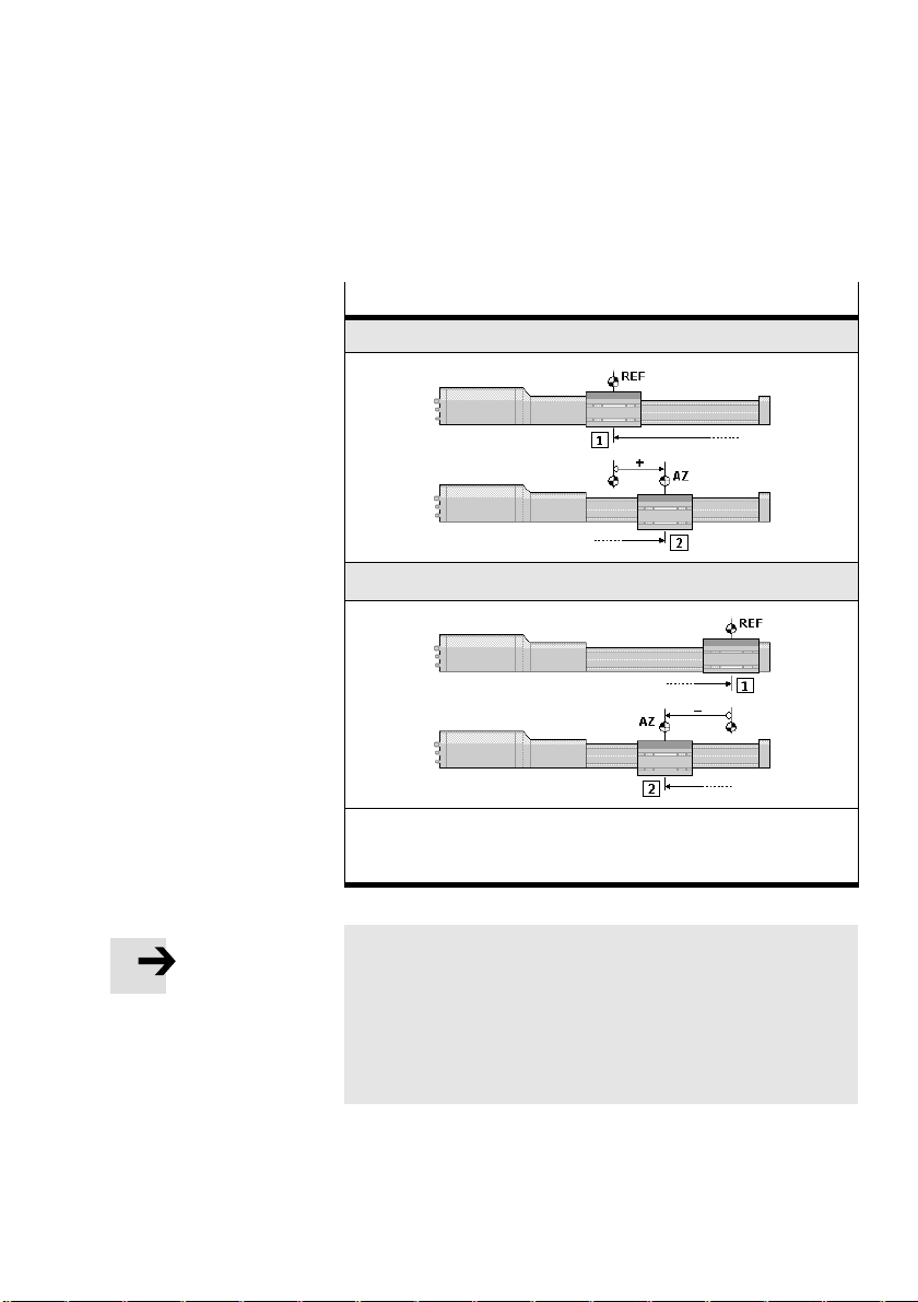
5. Commissioning
Notes on referencing to the fixed stop
"Fixed stop" referencing method
Negative fixed stop (near motor) = factory setting
Positive fixed stop (remote from motor)
Festo P.BE−MTR−DCI−EN en 0411NH
1 Axis moves at search speed v
2 Axis moves at speed vs0 from the reference point to the axis zero
point AZ.
to the mechanical fixed stop.
sw
Please note
homing may only be carried out directly against the fixed
stop, if the permitted impact pulse is not exceeded.
Maximum impact pulse = mass x speed
Please refer to the manual for your servo
drive for the per
mitted value.
5−13
Page 96

5. Commissioning
Caution
Damage to components
The MTR−DCI moves to the stop during homing at 1.5 times
the rated motor torque. (150% of the rated current)
· Limit the maximum current during homing by means of
FCT software (see help for PlugIn MTR−DCI)
CI command "Object 6073 Max. current" (see appen
dix B.1)
Please note that the current limitation also limits
the maxi
mum possible speed and that (higher) nominal speeds
may not therefore be achieved.
Caution
Damage to components
During operation it is not permitted to move to the mech
anical end positions (stops). If movement is made to the
end positions with a heavy load, the end positions may
become blocke
· Set the offset of the axis zero point š 0.
· Limit the positioning range by defining valid softwere
d.
end positions during commissioning (see chapter 1.1.2).
· Specify target positions only within the permitted posi
tioning range.
5−14
Festo P.BE−MTR−DCI−EN en 0411NH
Page 97
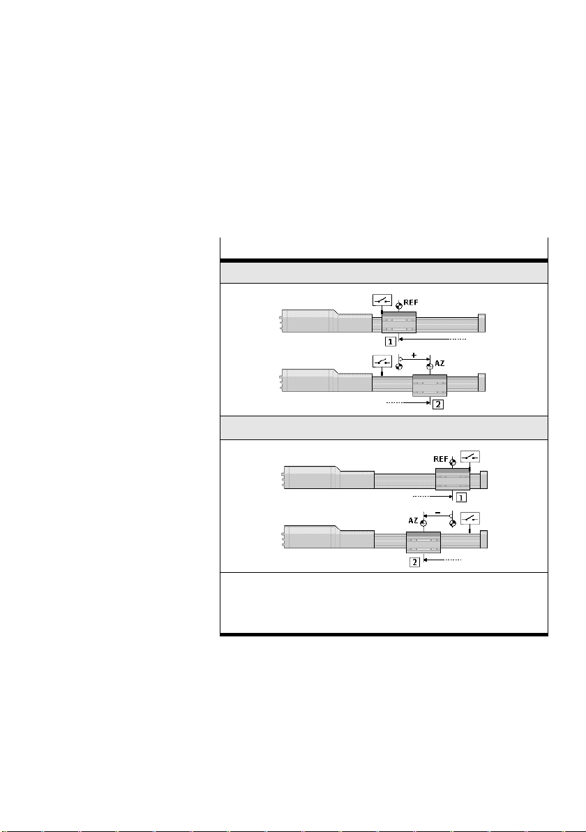
5. Commissioning
Notes on referencing to the reference switch
If homing to a mechanical end position is not possible in the
application, an external sensor (reference switch) can be used
as reference signal (see also chapter 1.1.2).
Referencing method "Reference switch"
Reference switch, negative (near motor)
Reference switch, positive (remote from motor)
Festo P.BE−MTR−DCI−EN en 0411NH
1 Axis moves at search speed vsw to the reference switch, and it
reverses to ascertain the reference point.
2 Then axis moves at speed vs0 from the reference point to the axis
zero point.
5−15
Page 98

5. Commissioning
} Settings
Homing parameter
Homing method
Velocity v_
Velocity v_
Save
Setting parameters
· Set the following homing parameters one after the other:
sw
s0
the referencing method [Homing method]
the search speed for ascertaining the reference point
[Velocity v_sw]
the positioning speed to the
axis zero point. [Velocity
v_s0].
Caution
If the referencing method is changed, the offset of the axis
zero point will be reset to zero. Existing settings of the soft
ware end positions and of the target positions of the posi
tion set table will be retained. Note that these values refer
to the previous axis zero point.
· Always carry out homing after changing the referencing
method.
· Then teach the offset of the axis zero point.
If the axis zero point is modified:
· teach the software end positions and the target posi
tions again.
· Accept each setting with OK<Enter>. The setting will then
become effective in the drive.
· Save the parameter settings with the menu command
[Save]. Only then will the settings be retained even if the
power supply is switched off or if there is a power failure.
· Finally, carry out homing, otherwise the previous refer
ence system of the MTR−DCI will remain unmodified.
5−16
Festo P.BE−MTR−DCI−EN en 0411NH
Page 99

5. Commissioning
5.3.3 Carrying out homing
Warning
Danger of injury.
Electric axes can move suddenly with high force and at
high speed. Collisions can lead to serious injury to human
beings and damage to components.
· Make sure that nobody can gain access to the operating
The drive moves during homing at first at the preset search
speed v_sw corresponding to the selected referencing
method up to the mechanical fixed stop (or reference
and when the signal has beeen evaluated, takes up the posi
tion as reference point. (Fig.5/1 1)
range of the axis or of other connected actuators and
that no objects lie in the path of the axis while the sys
tem is still connected to
a power supply.
switch)
The drive then moves at speed v_s0 to the axis zero point.
(Fig.5/1
2)
1 Travel to the
reference point
REF
2 Travel to the axis
zero point AZ
Fig.5/1: Homing (example: Fixed stop, negative)
Festo P.BE−MTR−DCI−EN en 0411NH
REF
1
AZ
2
5−17
Page 100
5. Commissioning
After successful homing the drive stands at the axis zero
point. With first commissioning or after a change of referenc
ing method the offset of the axis zero point = 0; the drive
then stands afte
r homing at the reference point (= axis zero
point).
Starting homing
The following conditions must be fulfilled for homing:
The axis must be set up completely, wired and supplied
with power.
The MTR−DCI must be correctly parametrized.
Please note
When carrying out homing note that:
the drive must be in the permitted positioning range.
the drive moves in the search direction corresponding to
the seleced referencing method and at the
standin front of the stop or reference switch.
start must
5−18
1. Position the drive in the Teach mode so that at the start in
the search direction it standsin front of the stop or refer
ence switch.
· Select e.g. [Settings] [Position set] [Position] (see also
chapter 5.4.1).
· Move the drive to the desired position manually with
the arrow buttons.
· Interrupt the procedure with ESC<menu>, in order that
the position is not included in the position set table.
Festo P.BE−MTR−DCI−EN en 0411NH
 Loading...