

Festo MS-LFM-...-DP Series, MS-LFM-...-DN Series, MS-LFM-...-DPI Series, MS-LFM-...-DNI Series Operating Instructions Manual
Page 1
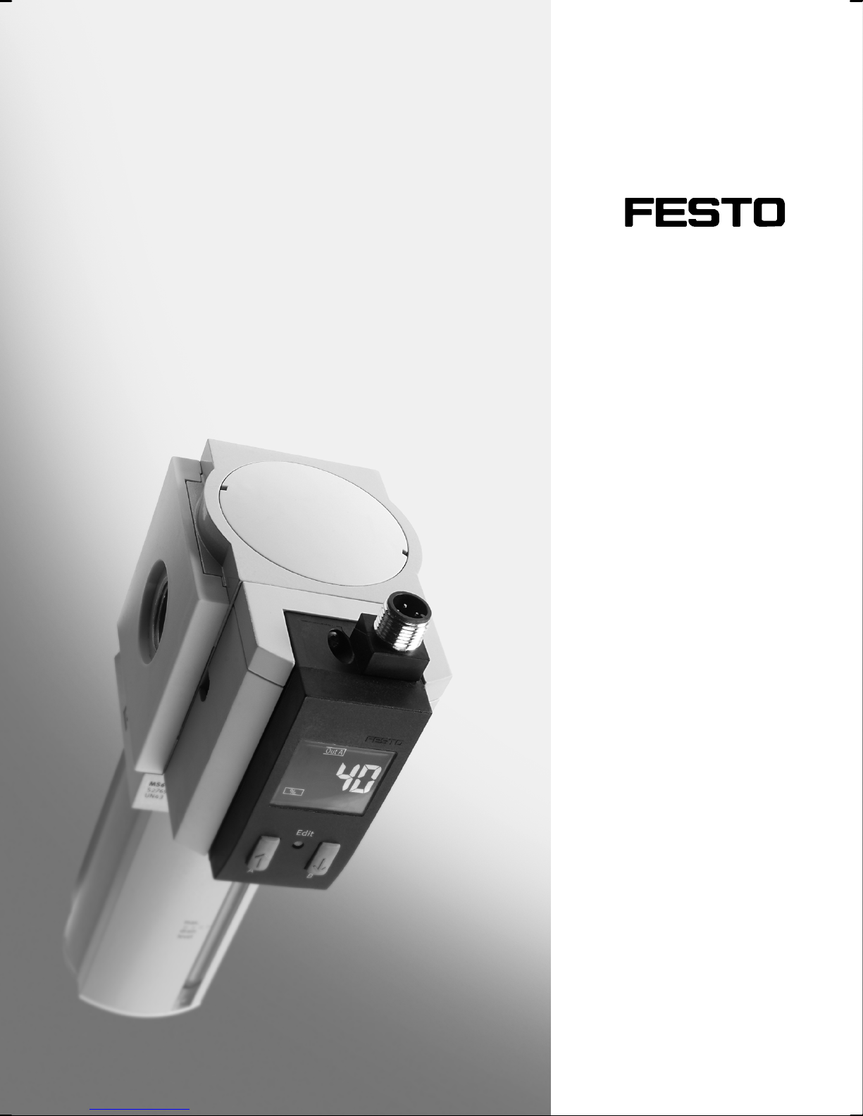
Filterverschmutzungserkennung
mit Anzeige
Filter contamination recognition
with display
MSŪ−LFM−Ū−DP/DN/DPI/DNI
(de) Bedienungs−
anleitung
(en) Operating
instructions
711 942
0611NH
Page 2
MSŪ−LFM−Ū−DP/DN/DPI/DN I
Symbole/Symbols:
Warnung
Warning, Caution
Hinweis
Please note
Umwelt
Antipollution
Zubehör
Accessories
Einbau und Inbetriebnahme nur von qualifi
ziertem Fachpersonal, gemäß Bedienungs
anleitung.
Fitting and commissioning to be carried out
by qualified personnel only in accordance
with the operating instructions.
Deutsch 3 . . . . . . . . . . . . . . . . . . . . . . . . . . . .
English 29 . . . . . . . . . .
2
. . . . . . . . . . . . . . . . . . . . . . . . . . . . . . . . . . . . . . . . . . . . . . . . . . . . . . . . . .
. . . . . . . . . . . . . . . . . . . . . . . . . . . . . . . . . . . . . . .
Festo MSŪ−LFM−Ū−DP/DN/DPI/DNI 0611NH
Page 3

MSŪ−LFM−Ū−DP/DN/DPI/DN I
Filterverschmutzungserkennung mit Anzeige
MSŪ−LFM−Ū−DP/DN/DPI/DNIDeutsch
Inhaltsverzeichnis
1 Bedienteile und Anschlüsse4 . . . . . . . . . . . . . . . . . . . . . . . . . . . . . . . . . . . .
2Funktion und Anwen
3Voraussetzungen für den Produkteinsatz 7
4 Einbau 7 . . . . . . . . . . . . . . . . . . . . . . .
Mechanisch/Pneumatisch 7 . . . . . . . . . . . . . . . . . . .
Elektrisch 8 . . . . . . . . . . . . . . . . . . . . . . . . . . . . . .
5 Inbetriebnahme10 . . . . . . . . . . . . . . . . . . . . . . . . .
Symbolik auf dem Display 10 . . . . . . . . . . . . . . . . . . . . . . . . .
Schnellinbetriebnahme mit Werkseinstellung 12 . . . . . . . . . . . . . . . . . . . . . .
6 Bedienung und Betrieb 13 . . . . .
RUN−Modus 13 . . . . . . . . . . . . . .
SHOW−Modus 14 . . . . . . . . . . . . . .
EDIT−Modus 14 . . . . . . . . . . . . . . .
TEACH−Modus (nur bei eingestellter Einheit %" möglich) 18 . . . . . . . . .
Hinweise für einen fehlerfreien Betrieb 19 . . . . . . . . . . . . . . . . . . . . . . . . . . . .
Das Gerät auf Werkseinstellung zurücksetzen 19 . . . . . . . . .
7Wartung und Pflege20 . . . . . . . . . . . . . . . . . . . . . . . . . . . . . .
dung 5 . . . . . . . . . . . . . . . . . . . . . . . . . . . . . . . . . . . . . .
. . . . . . . . . . . . . . . . . . . . . . . . . . . . . . .
. . . . . . . . . . . . . . . . . . .
. . . . . . . . . . . . . . . . . . . . . .
. . . . . . . . . . . . . . . . . . . . .
. . . . . . . . . . . . .
. . . . . . . . . . . . . . . . . . . . . . . . . . . . . . . . . . .
. . . . . . . . . . . . . . . . . . . . . . . . . . . . . . . . . . . .
. . . . . . . . . . . . . . . . . . . . . . . . . . . . . . . . . .
. . . . . . . . . . . . . . . . . . . . . . . . . . . . . . . . . . .
. . .
. . . . . . . . . . . . .
. . . . . . . . . . . . .
. . . . . . . . . . . . . . . . . . . . . . . . .
8Zubehör 20 . . . . . . . . . . . . . . . . . . . . . . . . . . . . . . . . . . . .
9 Störungsbeseitigung 20 . . . . . . . . . . . . . . . . . . . . . . . . . .
10 Technische Daten 22 . . . . . . . . . . . . . . . . . . . . . . . . . . . . . .
11 Menüstruktur24 . . . . . . . . . . . . . . . . . . . . . . . . . . . . . . .
Festo MSŪ−LFM−Ū−DP/DN/DPI/DNI 0611NH Deutsch
. . . . . . . . . . . . . . . . .
. . . . . . . . . . . . . . . .
. . . . . . . . . . . . . . .
. . . . . . . . . . . . . . . . .
3
Page 4
MSŪ−LFM−Ū−DP/DN/DPI/DN I
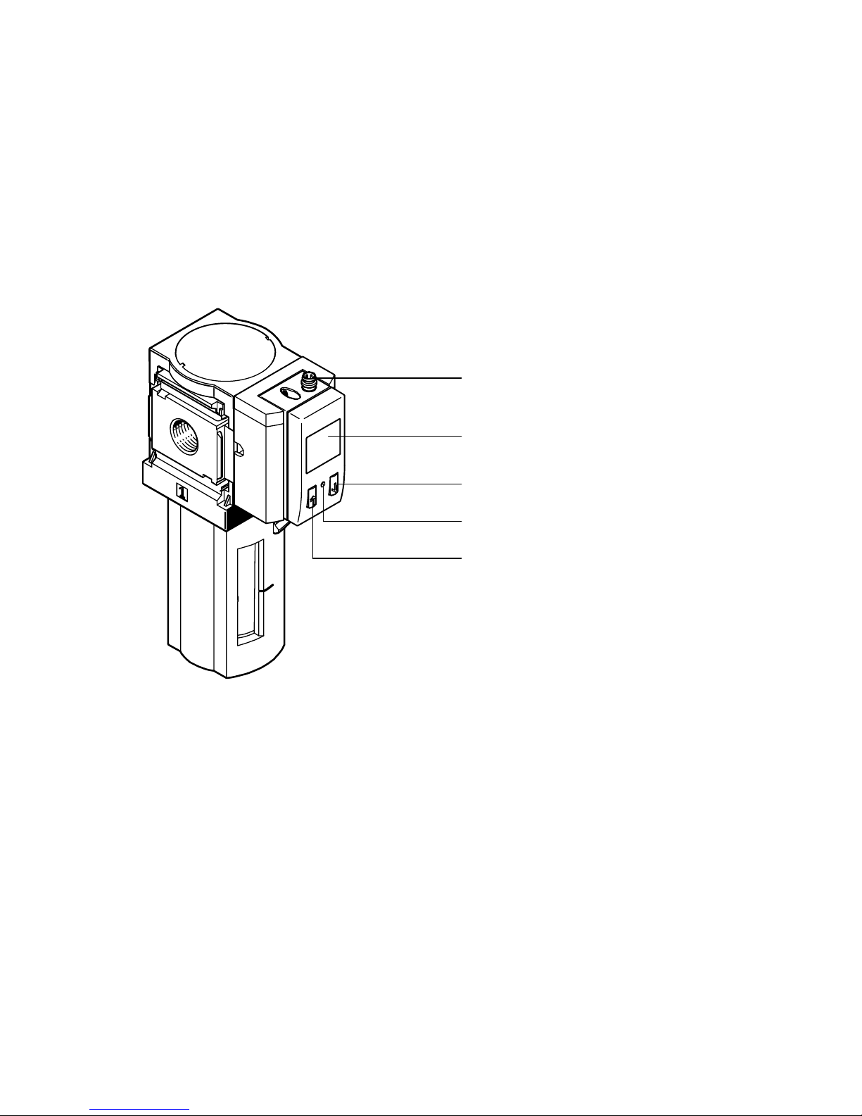
1 Bedienteile und Anschlüsse
Fein−/Feinstfilter MSŪ−LFM mit Filterverschmutzungserkennung mit Anzeige
MSŪ−LFM−Ū−DP/DN/DPI/DN I
1
2
3
1 Elektrischer Anschluss
(Ausführung abhängig vom Typ)
2 Display
Bild1
4
5
3 DOWN−Taste
4 EDIT−Knopf
5 UP−Taste
4
Festo MSŪ−LFM−Ū−DP/DN/DPI/DNI 0611NH Deutsch
Page 5

MSŪ−LFM−Ū−DP/DN/DPI/DN I
2 Funktion und Anwendung
Die Filterverschmutzungserkennung mit Anzeige MSŪ−LFM−Ū−DP/DN/DPI/DNI
dient bestimmungsgemäß zur Überwachung des Verschmutzungsgrads im
Fein−/Feinstfilter MSŪ−LFM. Der Verschmutzungsgrad ergibt sich durch die fortlau
fende Messung des Differenzdrucks, der bei steigender Verschmutzung zunimmt.
Die Messung wird über ein piezoresistives Sensorelement mit nachgeschalteter
elektronischer Einheit ausgewertet. Das Messergebnis wird nummerisch im Display
angezeigt. Die Anbindung
gang. Der Schaltpunkt für den Filterpatronenwechsel ist einstellbar.
Die Schaltausgänge lassen sich als Öffner und Schließer konfigurieren. Die ge
wünschten Schaltpunkte lassen sich als Schwellwert− oder Fenster−Komparator
festlegen. Die Produktausführungen MSŪ−LFM−Ū−DPI/DNI bieten zusätzlich einen
Analogausgang, der den gemessenen Differenzdruck als elektrisches druckpropor
tionales Signal
weiterleitet.
an übergeordnete Systeme erfolgt über einen Schaltaus
Begriff
Differenzdruck Druckabfall im Fein−/Feinstfilter MSŪ−LFM zwischen Eingang und
Maxdruck 350mbar
Basisdruck Mittelwert aller gemessenen Differenzdruckwerte in einem
Max. Basisdruck 300mbar
Erklärung
Ausgang. Der Differenzdruck ist abhängig vom Durchfluss und
vom Verschmutzungsgrad.
Festgelegter Endwert für den Differenzdruck in der Einheit %.
Der Wert entspricht 100%. Bei Erreichen dieses Werts empfiehlt
es sich die Filterpatrone zu wechseln.
bestimmten Zeitintervall. Der Basisdruck ist der Startwert für die
Filterverschmutzungserkennung bei Prozentanzeige
(0%Verschmutzung entspricht Filterneuzustand).
Für eine fehlerfreie Filterverschmutzungserkennung ist die Ermitt
lung des Basisdrucks notwendig. Ein neuer Filter weist einen be
stimmten Druckabfall auf, der nicht als Filterverschmutzungsgrad
erkannt werden darf.
Der ermittelte Basisdruck muss kleiner als der max. Basisdruck
sein, sonst wird ein Fehler im Display angezeigt.
Festo MSŪ−LFM−Ū−DP/DN/DPI/DNI 0611NH Deutsch
5
Page 6

MSŪ−LFM−Ū−DP/DN/DPI/DN I
Begriff Erklärung
Zeitkonstante
Messwertglättung
1s, 5s, 20s
Wählbares Zeitfenster für die Messwertglättung. Die letzten
gemessenen Differenzdruckwerte innerhalb dieses Zeitfensters
werden zur Mittelwertbildung herangezogen. Die Gewichtung von
einzelnen Fehlmessungen (z.B. durch Durchflussschwankungen)
wird bei einem größeren Zeitfenster verringert. Der geglättete
Mittelwert wird auf dem Display angezeigt und legt den Zustand
des Schaltausgangs fest.
Hinweis für die Produktausführungen MSŪ−LFM−Ū−DPI/DNI mit
Analogausgang:
Auf das Signal am Analogausgang hat die Messwertglättung keine
Auswirkung. Das Signal wird ungeglättet ausgegeben.
Einheit %, bar, kPa, psi
Zeigt den geglätteten Differenzdruck−Mittelwert in der entspre
chenden Einheit.
Besonderheiten bei Einheit %":
S Grobe Stufung in 5−%−Schritten, ohne 5%, 10% und 15%,
d.h. 0%, 20%, 25%, Ū , 100%
S Werte größer 100% können nicht angezeigt werden, wenn
der Differenzdruck über 350mbar (Maxdruck) steigt.
Die Anzeige 100% blinkt auf dem Display.
Schaltschwelle/
Schaltpunkt
Hysterese Einstellbare Verzögerung beim Rücksetzen des Schaltausgangs in
Bild2
6
Einstellbarer Schaltdruck. Erreicht der geglättete Differenzdruck−
Mittelwert den Schaltpunkt wird ein Signal auf dem Schaltaus
gang ausgegeben (è Bild10).
seinen definierten Ursprungszustand (è Bild10).
Festo MSŪ−LFM−Ū−DP/DN/DPI/DNI 0611NH Deutsch
Page 7
MSŪ−LFM−Ū−DP/DN/DPI/DN I
3 Voraussetzungen für den Produkteinsatz
Hinweis
Durch unsachgemäße Handhabung entstehen Fehlfunktionen.
S Stellen Sie sicher, dass die folgenden Vorgaben stets eingehalten werden.
S Vergleichen Sie die Grenzwerte in dieser Bedienungsanleitung mit denen Ihres
Einsatzfalls (z.B. Betriebsmedium, Drücke, Kräfte, Momente, Temperaturen,
Massen, Geschwindigkeiten, Spannungen).
S Berücksichtigen Sie die Umgebungsbedingungen am Einsatzort.
S Berücksichtigen Sie die Vorschriften der Berufsgenossenschaft, des Techni
schen Überwachungsvereins oder
entsprechende nationale Bestimmungen.
S Entfernen Sie die Transportvorkehrungen wie Schutzwachs, Folien (Polyamid),
Kappen (Polyethylen), Kartonagen.
Die Verpackungen sind vorgesehen für eine Verwertung auf stofflicher Basis
(Ausnahme: Ölpapier = Restmüll).
S Verwenden Sie den Artikel im Originalzustand ohne jegliche eigenmächtige
Veränderung.
4Einbau
Mechanisch/Pneumatisch
Die Filterverschmutzungserkennung mit Anzeige MSŪ−LFM−Ū−DP/DN/DPI/DNI ist
ab Werk auf dem Fein−/Feinstfilter MSŪ−LFM montiert. Es sind keine Montagearbei
ten erforderlich.
Festo MSŪ−LFM−Ū−DP/DN/DPI/DNI 0611NH Deutsch
7
Page 8
MSŪ−LFM−Ū−DP/DN/DPI/DN I
Elektrisch
Warnung
S Verwenden Sie ausschließlich Stromquellen, die eine sichere elektrische
Trennung der Betriebsspannung nach IEC/DIN EN 60204−1 gewährleisten.
Berücksichtigen Sie zusätzlich die allgemeinen Anforderungen an PELV−
Stromkreise gemäß IEC/DIN EN 60204−1.
Hinweis
Lange Signalleitungen reduzieren die Störfestigkeit.
S Stellen Sie sicher, dass die Signalleitungen stets kürzer sind als 30 m.
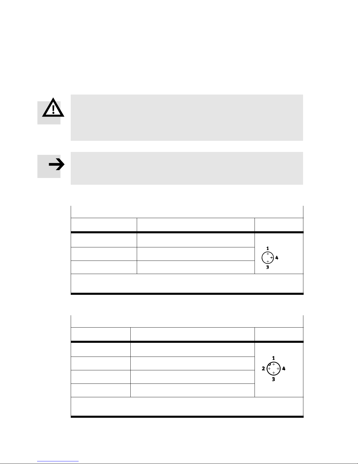
S Verkabeln Sie das Gerät wie folgt:
MSŪ−LFM−Ū−DP/DN−Ū (1 Schaltausgang)
Pin / Kabelfarben
1)
Belegung M8x1, 3−polig Stecker
1 / braun (BN) +24VDC Versorgungsspannung M8x1, 3−polig
4 / schwarz (BK) Ausgang A (Out A)
3 / blau (BU) 0 V
1)
Bei Verwendung des Steckdosenkabels lt. Zubehör
2)
Anziehdrehmoment: max. 0,3Nm
Bild3
2)
MSŪ−LFM−Ū−DPI/DNI−Ū (1 Schaltausgang und 1 Analogausgang)
Pin / Kabelfarben
1)
Belegung M12x1, 4−polig Stecker
1 / braun (BN) +24VDC Versorgungsspannung M12x1, 4−polig
2 / weiß (WH) Ausgang A (Out A)
3 / blau (BU) 0 V
2)
4 / schwarz (BK) Analogausgang 4Ū20mA
1)
Bei Verwendung des Steckdosenkabels lt. Zubehör
2)
Anziehdrehmoment: max. 0,5Nm
Bild4
8
Festo MSŪ−LFM−Ū−DP/DN/DPI/DNI 0611NH Deutsch
Page 9
MSŪ−LFM−Ū−DP/DN/DPI/DN I
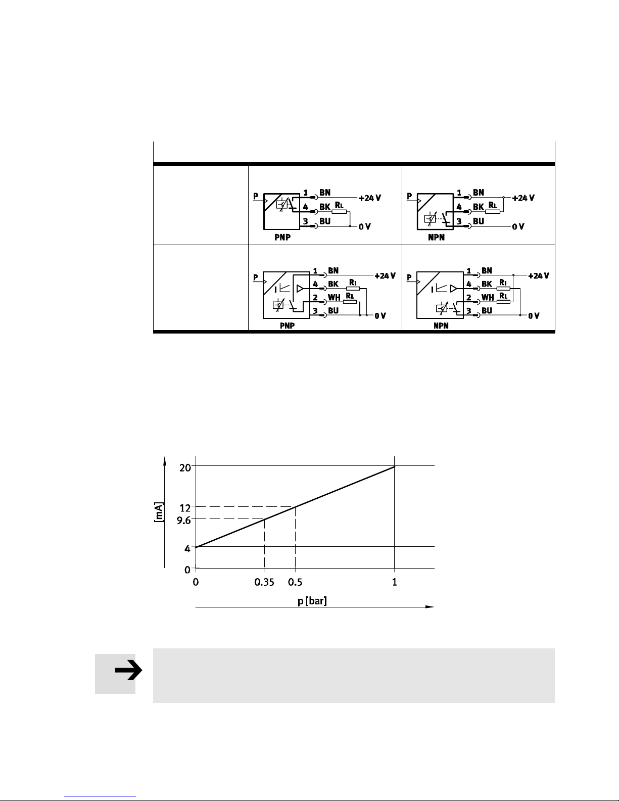
Schaltbilder
1 Schaltausgang MSŪ−LFM−Ū−DP−Ū MSŪ−LFM−Ū−DN−Ū
1Schaltausgang
und 1Analog−
ausgang
Bild5
MSŪ−LFM−Ū−DPI−Ū MSŪ−LFM−Ū−DNI−Ū
Analogausgang (nur bei MSŪ−LFM−Ū−DPI/DNI)
Am Analogausgang liegt der Differenzdruck−Messwert als elektrisches druck
proportionales Signal an, d.h. der Druckmessbereich 0Ū1bar entspricht einem
elektrischen Signal im Bereich 4Ū20mA.
Bild6
Hinweis
Auf das Signal am Analogausgang hat die Messwertglättung keine Auswirkung.
Das Signal wird ungeglättet ausgegeben.
Festo MSŪ−LFM−Ū−DP/DN/DPI/DNI 0611NH Deutsch
9
Page 10
MSŪ−LFM−Ū−DP/DN/DPI/DN I
5 Inbetriebnahme
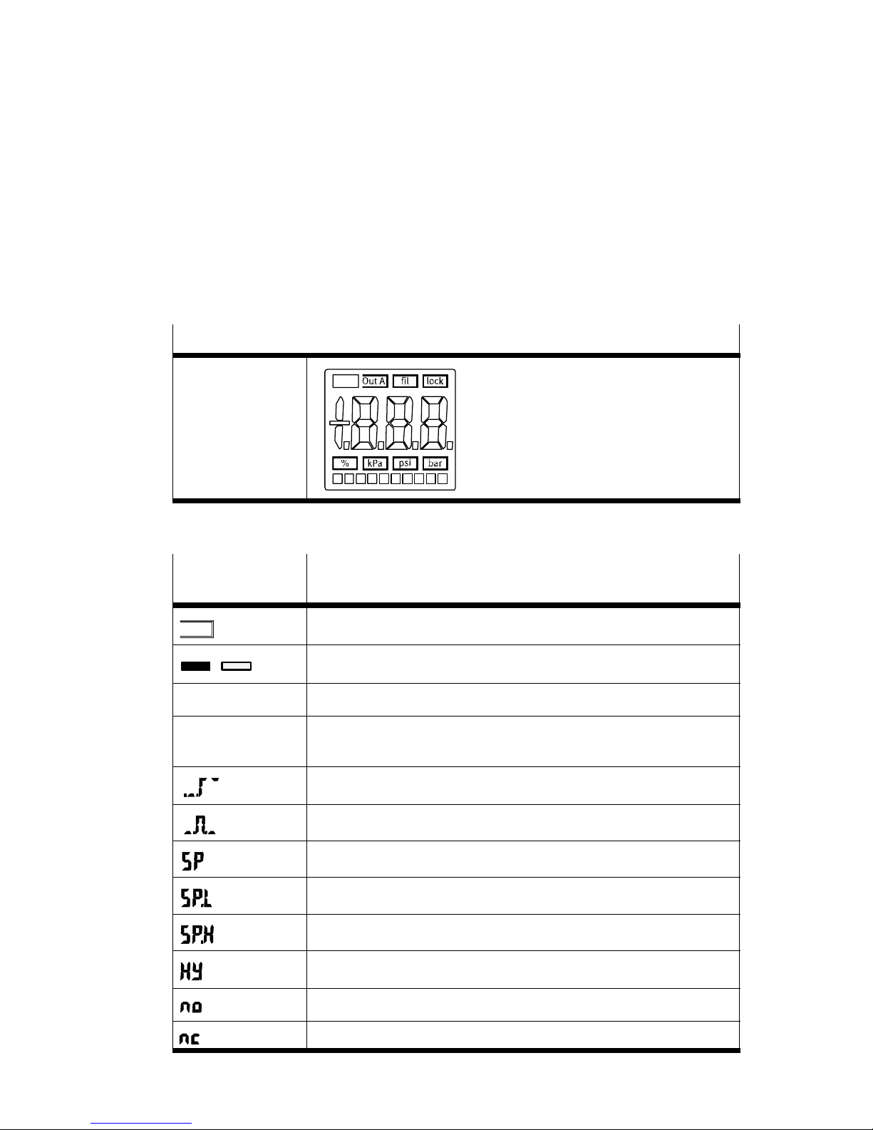
Symbolik auf dem Display
Leucht−LCD−Anzeige
Display,
ableseoptimiert
Bild7
Symbolik auf
Beschreibung
dem Display
Out A
/
[fil] blinkt bei Eingabe der Zeitkonstante Messwertglättung
[lock] leuchtet bei aktiver Sicherheitssperre (Sperrung gegen unbefugte
Schaltausgang A
Schaltausgang gesetzt / nicht gesetzt
Programmierung)
Schwellwert−Komparator
Fenster−Komparator
Schaltdruck
Unterer Schaltdruck
Oberer Schaltdruck
10
Hysterese
Schließer (normally open)
Öffner (normally closed)
Festo MSŪ−LFM−Ū−DP/DN/DPI/DNI 0611NH Deutsch
Page 11
MSŪ−LFM−Ū−DP/DN/DPI/DN I
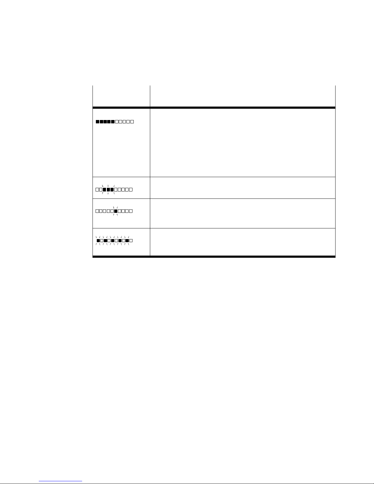
Symbolik auf
dem Display
Bild8
Beschreibung
Segmente leuchten: Grafische Anzeige des aktuellen
Differenzdruck−Mittelwerts bezogen auf den max. Wert des
Messbereichs, d.h.
S bei Einheit bar stellt der Balken den Bereich 0 bis 1 bar dar
(entsprechende Werte bei Einheit kPa" und psi")
S bei Einheit %" stellt der Balken den Bereich von 0% bis
100% dar. Im Gegensatz zur Zahlenanzeige stellt die Balken
anzeige auch Werte im Bereich zwischen 0% und 20% dar.
3 Segmente blinken:
Hysteresewert wird angezeigt
1 Segment blinkt angezeigt wird:
Segment 5: Schaltpunkt SP oder SP.L
Segment 8: Schaltpunkt SP.H
5 Segmente blinken:
Basisdruck wird im SHOW−Modus angezeigt oder im TEACH−
Modus ermittelt
Festo MSŪ−LFM−Ū−DP/DN/DPI/DNI 0611NH Deutsch
11
Page 12

MSŪ−LFM−Ū−DP/DN/DPI/DN I
Schnellinbetriebnahme mit Werkseinstellung
Die Filterverschmutzungserkennung mit Anzeige MSŪ−LFM−Ū−DP/DN/DPI/DNI
wird mit folgender Werkseinstellung ausgeliefert:
Werkseinstellung
Einheit %
Schaltschwelle/Schaltpunkt [%] 100
Schaltverhalten Schwellwert−Komparator
Schaltcharakteristik no (normally open Schließer)
Hysterese [%] 5
Basisdruck [mbar] 20
Zeitkonstante Messwertglättung [s] 1
1)
entspricht einem Differenzdruck von 350mbar (Maxdruck)
Bild9
1)
Ermi tte l n Sie nach Einbau des neuen Fein−/Feinstfilters MSŪ−LFM in Ihre Anlage den
Basisdruck (nur bei eingestellter Einheit %" möglich):
1. Betriebsspannung für die Filterverschmutzungserkennung mit Anzeige
MSŪ−LFM−Ū−DP/DN/DPI/DN I einschalten.
Das Gerät befindet sich automatisch im RUN−Modus (Grundstellung). Wenn Sie
nicht sicher sind, ob sich das Gerät im RUN−Modus befindet, halten Sie 1s
den
EDIT−Knopf gedrückt. Das Gerät ist dann im RUN−Modus.
2. Anlage in Betrieb nehmen.
Warten Sie einige Zeit, bis Druckschwankungen in Ihrer Anlage sich auf ein
Minimum reduziert haben.
3. Um die Messung zu starten, zuerst die DOWN−Taste, dann zusätzlich EDIT−
Knopf drücken.
5 Segmente in der Balkenanzeige blinken. Es wird fortlaufend der Differenz
druck gemessen. Wird
kehrt das Gerät ohne Änderung in den RUN−Modus zurück.
4. Um die Messung zu beenden, erneut DOW N−Taste und zusätzlich EDIT−Knopf
drücken.
Das Gerät ist wieder im RUN−Modus.
12
die Messung nach maximal 15 Minuten nicht beendet,
Festo MSŪ−LFM−Ū−DP/DN/DPI/DNI 0611NH Deutsch
Page 13
MSŪ−LFM−Ū−DP/DN/DPI/DN I
Aus den gemessenen Differenzdruckwerten wird der Basisdruck berechnet
und abgespeichert. Das Display zeigt 0% Verschmutzung an. Im Fehlerfall wird
Err" angezeigt (è Abschnitt 9, Störungsbeseitigung).
Im Laufe des Betriebs verschmutzt der Filter. Den Grad der Verschmutzung
zeigt die steigende Prozentzahl an.
Übersteigt der gemessene Differenzdruck die Schaltschwelle von 350mbar
(Maxdruck), wird im Display
angezeigt. Gleichzeitig wird ein Signal auf dem Schaltausgang ausgegeben.
Die Filterpatrone sollte nun gewechselt werden.
Hinweis
Nach einem Wechsel der Filterpatrone muss der Basisdruck nicht neu ermittelt
werden. Erst wenn sich die Einsatzbedingungen für den Fein−/Feinstfilter än
dern (z. B. Einbau in eine neue Anlage oder Änderungen am Druckluftsystem)
muss der Basisdruck neu ermittelt werden.
ein blinkender Verschmutzungsgrad von 100%
6 Bedienung und Betrieb
Voraussetzung:
S Das Gerät ist eingeschaltet.
Hinweis
Eine Übersicht zur Menüstruktur finden Sie in Abschnitt 11.
RUN−Modus
Im RUN−Modus wird der Verschmutzungsgrad des Filters (geglättete Differenzdruck−
Mittelwert), die eingestellte Einheit und der Signalzustand des Schaltausgangs
Out A angezeigt. Ein blinkender Wert bedeutet, dass der Messbereich überschritten
ist.
Aus anderen Modi heraus ist der RUN−Modus erreichbar durch:
Drücken des EDIT−Knopfs für 1s
Ablauf einer Überwachungszeit (Timeout è Abschnitt 11, Menüstruktur).
Festo MSŪ−LFM−Ū−DP/DN/DPI/DNI 0611NH Deutsch
13
Page 14
MSŪ−LFM−Ū−DP/DN/DPI/DN I
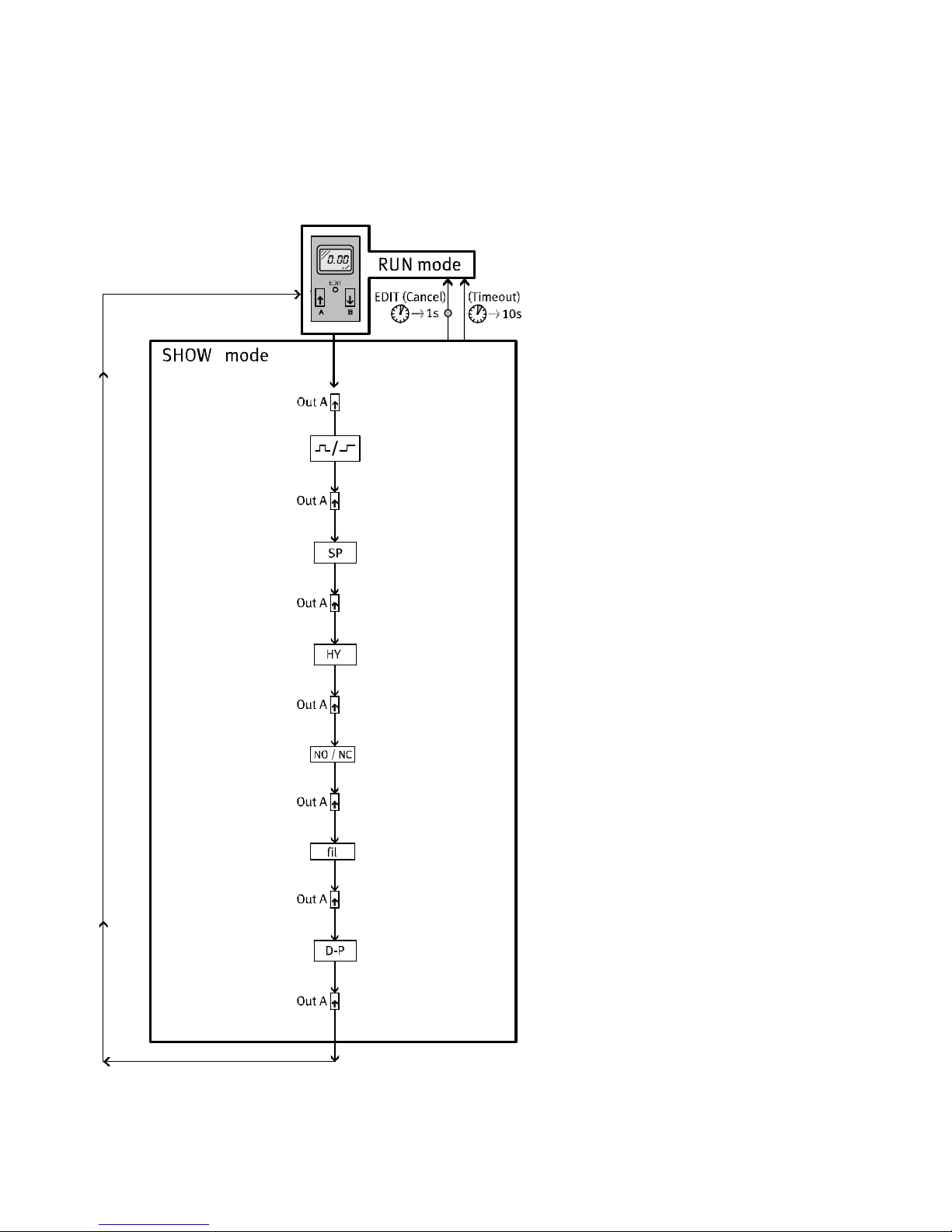
SHOW−Modus
Wenn sich das Gerät im RUN−Modus befindet, wird nach Drücken der UP−Taste der
SHOW−Modus aktiv. Mit jeder weiteren Betätigung der UP−Taste werden nachein
ander die aktuellen Einstellungen des Schaltausgangs angezeigt. Nach Durch
schalten aller Werte erfolgt die Rückkehr in den RUN−Modus.
Folgende Einstellungen und Werte werden angezeigt:
Schaltfunktion [Schwellwert− oder Fenster−Komparator]
Schaltpunkte
[SP] oder [SP.L] und [SP.H]
Hysterese [HY]
Schaltcharakteristik [no/nc]
Zeitkonstante Messwertglättung [fil]
Basisdruck [D−P]
Hinweis bei eingestellter Einheit [%]:
Ein blinkender Wert von 100% beim Schaltpunkt bedeutet, das ein Wert größer
als der Maxdruck (350mbar) gewählt wurde. Eingestellt wurde der höhere Wert in
der Einheit bar", kPA" oder psi". Überprüfen Sie in diesem Fall Ihre
Einstellungen.
EDIT−Modus
Hinweis
Zuerst Basisdruck ermitteln (èTEACH−Modus), bevor Einstellungen im
EDIT−Modus vorgenommen werden.
Folgende Einstellungen können im EDIT−Modus vorgenommen werden:
Schaltfunktion (Schwellwert− oder Fenster−Komparator)
Schaltpunkte [SP] oder [SP.L] und [SP.H]
Hysterese [HY]
Schaltcharakteristik [no/nc] (Öffner/Schließer)
Zeitkonstante Messwertglättung [fil]
Einheit (%, kPA, psi, bar) und Sicherheitscode (lock).
14
Festo MSŪ−LFM−Ū−DP/DN/DPI/DNI 0611NH Deutsch
Page 15
MSŪ−LFM−Ū−DP/DN/DPI/DN I
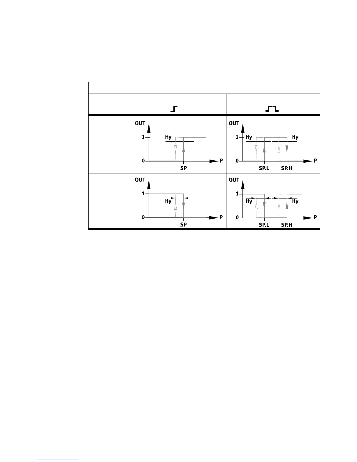
Übersicht Schaltpunkte (SPŪ) und Hysterese (Hy)
Bei Einstellung Schwellwert−
Komparator
Bei Einstellung
no (Schließer)
Bei Einstellung
nc (Öffner)
Bild10
Bei Einstellung Fenster−
Komparator
Hinweise:
Bei einem Wechsel der Schaltfunktion müssen die Schaltpunkte überprüft und
ggf. neu eingestellt werden.
In der Einheit %" kann für die Hysterese sowie für den Schaltpunkt der Wert
100% eingestellt werden. Der Wert von 100% entspricht beim Schaltpunkt
einen Wert von 350mbar (Maxdruck), bei der Hysterese einen Wert von
330mbar.
Festo MSŪ−LFM−Ū−DP/DN/DPI/DNI 0611NH Deutsch
15
Page 16
MSŪ−LFM−Ū−DP/DN/DPI/DN I
Einstellung des Schaltverhaltens der Schaltausgänge
Hinweis
Im EDIT−Modus werden Änderungen sofort wirksam und können Auswirkungen
auf das Schaltverhalten des Schaltausgangs haben.
S Aktivieren Sie den Passwortschutz (Sicherheitscode), um das versehentliche
Ändern durch unbefugte Dritte zu verhindern.
S Vollziehen Sie folgende Schritte:
1. Um den EDIT−Modus zu aktivieren, EDIT−Knopf drücken.
Nur bei aktiver Sicherheitssperre [lock] blinkt:
2. UP/DOWN−Taste drücken, bis der gewählte Sicherheitscode
eingestellt ist.
3. EDIT−Knopf drücken.
Bei richtiger Eingabe wird die Sicherheitssperre aufgehoben.
Bei falscher Eingabe bleibt die Sicherheitssperre aktiv und das Gerät kehrt
in den RUN−Modus zurück.
[Out A] blinkt.
4. Mit UP/DOWN−Taste zwischen
Einstellung der Schaltfunktionen [Out A] blinkt
oder
Einstellung der Einheit und des Sicherheitcodes [%], [kPA], [psi], [bar] und
[lock] blinken
wählen.
5. Zur
Bestätigung des gewählten Einstellmenüs EDIT−Knopf drücken.
è Einstellung der Schaltfunktionen
è Einstellung der Einheit und des Sicherheitcodes
Einstellung der Schaltfunktionen
Die aktuell eingestellte Schaltfunktion blinkt.
1. Gewünschte Schaltfunktion (Schwellwert−/Fenster−Komparator) wählen mit
UP/DOWN−Taste.
2. Zur Bestätigung EDIT−Knopf drücken.
[SP] oder [SP.L] wird kurz angezeigt. Segment 5 der Balkenanzeige blinkt.
16
Festo MSŪ−LFM−Ū−DP/DN/DPI/DNI 0611NH Deutsch
Page 17
MSŪ−LFM−Ū−DP/DN/DPI/DN I
3. Schaltpunkt (SP oder SP.L) einstellen mit UP/DOWN−Taste.
4. Zur Bestätigung EDIT−Knopf drücken.
Bei Schaltfunktion Fenster−Komparator:
[SP.H] wird kurz angezeigt. Segment 8 der Balkenanzeige blinkt.
5. Wert (SP.H) einstellen mit UP/DOWN−Taste.
SP.H liegt oberhalb von SP.L bis Endwert Einstellbereich.
6. Zur Bestätigung EDIT−Knopf drücken.
[HY] wird kurz angezeigt. 3 Segmente der Balkenanzeige blinken.
7. Hysterese (HY) einstellen mit UP/DOWN−Taste.
8. Zur
Bestätigung EDIT−Knopf drücken.
[no] oder [nc] blinkt.
9. Schaltcharakteristik (no/nc) einstellen mit UP/DOWN−Taste.
10. Zur Bestätigung EDIT−Knopf drücken.
[fil] blinkt.
11. Zeitkonstante Messwertglättung (1 oder 5 oder 20) einstellen mit UP/DOWN−
Taste.
12. Zur Bestätigung EDIT−Knopf drücken.
Das Gerät ist wieder im RUN−Modus.
Hinweis
Überprüfen Sie Ihre eingestellten Werte im SHOW−Modus.
Einstellung der Einheit und des Sicherheitscodes
Aktuelle Einheit ([%] oder [kPA] oder [psi] oder [bar]) blinkt.
1. Mit UP/DOWN−Taste die gewünschte Einheit wählen.
2. Zur Bestätigung EDIT−Knopf drücken.
[lock] blinkt.
3. Gewünschten Sicherheitscode mit UP/DOWN−Taste einstellen
(OFF = kein Schutz).
Festo MSŪ−LFM−Ū−DP/DN/DPI/DNI 0611NH Deutsch
17
Page 18
MSŪ−LFM−Ū−DP/DN/DPI/DN I
4. Zur Bestätigung EDIT−Knopf drücken.
Das Gerät ist wieder im RUN−Modus.
Tipp:
Sicherheitscode wiederauffindbar hinterlegen. Bei vergessenem Sicherheitscode
è Abschnitt Das Gerät auf Werkseinstellung zurücksetzen".
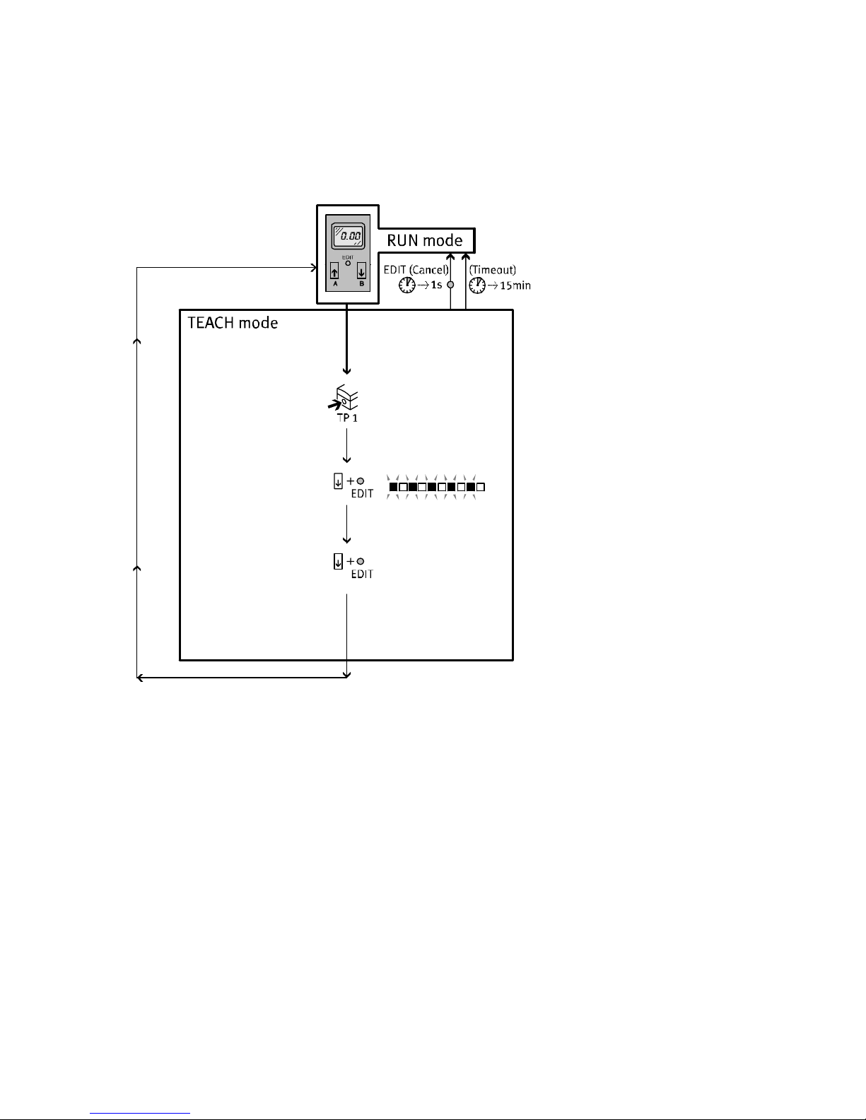
TEACH−Modus (nur bei eingestellter Einheit %" möglich)
Im TEACH−Modus wird der Basisdruck aus gemessenen Differenzdruckwerten inner
halb eines Zeitintervalls ermittelt. Der Basisdruck muss bei der Erstinbetriebnahme
des Fein−/Feinstfilters ermittelt werden.
Hinweis
Nach einem Wechsel der Filterpatrone muss der Basisdruck nicht neu ermittelt
werden. Erst wenn sich die Einsatzbedingungen für den Fein−/Feinstfilter
ändern (z.B. Einbau in eine neue Anlage oder Änderungen am Druckluftsystem)
muss der Basisdruck neu ermittelt werden.
S Gehen Sie wie folgt vor:
1. Anlage in Betrieb nehmen.
Warten Sie einige Zeit, bis Druckschwankungen in
Ihrer Anlage sich auf ein
Minimum reduziert haben.
2. Um die Messung zu starten, zuerst die DOWN−Taste, dann zusätzlich EDIT−
Knopf drücken.
5 Segmente in der Balkenanzeige blinken. Es wird fortlaufend der Differenz
druck gemessen. Wird die Messung nach maximal 15 Minuten nicht beendet,
kehrt das Gerät ohne Änderung in den RUN−Modus zurück.
3. Um die
Messung zu beenden, erneut DOWN−Taste und zusätzlich EDIT−Knopf
drücken.
Das Gerät ist wieder im RUN−Modus.
Aus den gemessenen Differenzdruckwerten wird der Basisdruck berechnet
und abgespeichert. Das Display zeigt 0% Verschmutzung an. Im Fehlerfall wird
Err" angezeigt (è Abschnitt 9, Störungsbeseitigung).
18
Festo MSŪ−LFM−Ū−DP/DN/DPI/DNI 0611NH Deutsch
Page 19

MSŪ−LFM−Ū−DP/DN/DPI/DN I
Hinweise für einen fehlerfreien Betrieb
Beachten Sie folgende Punkte:
S Um einen wirtschaftlichen und sicheren Betrieb zu gewährleisten, sollte der
Fein−/Feinstfilter im Differenzdruckbereich bis 350mbar betrieben werden.
S Ein anstehender Tausch der verschmutzten Filterpatrone kann durch geeignete
Schaltpunkteinstellung kleiner als 350mbar rechtzeitig erkannt werden.
S Der Differenzdruck im Fein−/Feinstfilter ist abhängig vom Durchfluss
und
Verschmutzungsgrad. Bei gleichbleibender Druckluftqualität und konstantem
Durchfluss lassen sich feste Tauschintervalle für die Filterpatrone planen.
S Der ermittelte Basisdruck ist abhängig von der Anlage und dem Durchfluss.
Ein hoher Durchfluss oder eine falsch dimensionierte Anlage führen zu einem
hohen Basisdruck. Dies verringert den Messbereich bis zur empfohlen Schalt
schwelle von 350mbar (Maxdruck).
S Ein
höher eingestellter Wert bei der Zeitkonstante Messwertglättung hilft
fehlerhaft ausgegebene Schaltsignale aufgrund von Durchflusssprüngen
(z.B.beim Einschalten der Anlage) zu vermeiden. Die Messwertglättung gilt
nur für den Schaltausgang. Der Analogausgang bei den Produktausführungen
MSŪ−LFM−Ū−DPI/DNI gibt sein Signal ungeglättet aus.
Das Gerät auf Werkseinstellung zurücksetzen
(auch bei nicht wiederauffindbarem Sicherheitscode)
Hinweis
Durch das Rücksetzen auf Werkseinstellung gehen die aktuellen Einstellungen
verloren.
S Notieren Sie bei Bedarf diese Einstellungen vor dem Rücksetzen.
Um das Gerät auf Werkseinstellung zurückzusetzen:
1. Schalten Sie die Betriebsspannung aus.
2. Drücken Sie gleichzeitig alle drei Einstellelemente (UP/DOWN−Taste und
EDIT−Knopf ) und schalten Sie dabei die Betriebsspannung wieder ein.
Auf dem Display erscheint rES".
Festo MSŪ−LFM−Ū−DP/DN/DPI/DNI 0611NH Deutsch
19
Page 20
MSŪ−LFM−Ū−DP/DN/DPI/DN I
7Wartung und Pflege
Zur Reinigung:
S Schalten Sie zur äußeren Reinigung folgende Energiequellen ab:
Betriebsspannung
Druckluft
S Reinigen Sie bei Bedarf den Fein−/Feinstfilter MSŪ−LFM−Ū und die Filterver
schmutzungserkennung mit Anzeige MS Ū−LFM−Ū−DP/DN/DPI/DNI von außen.
Zulässige Reinigungsmedien sind Seifenlauge (max. +50 °C) und werkstoff
schonende Medien.
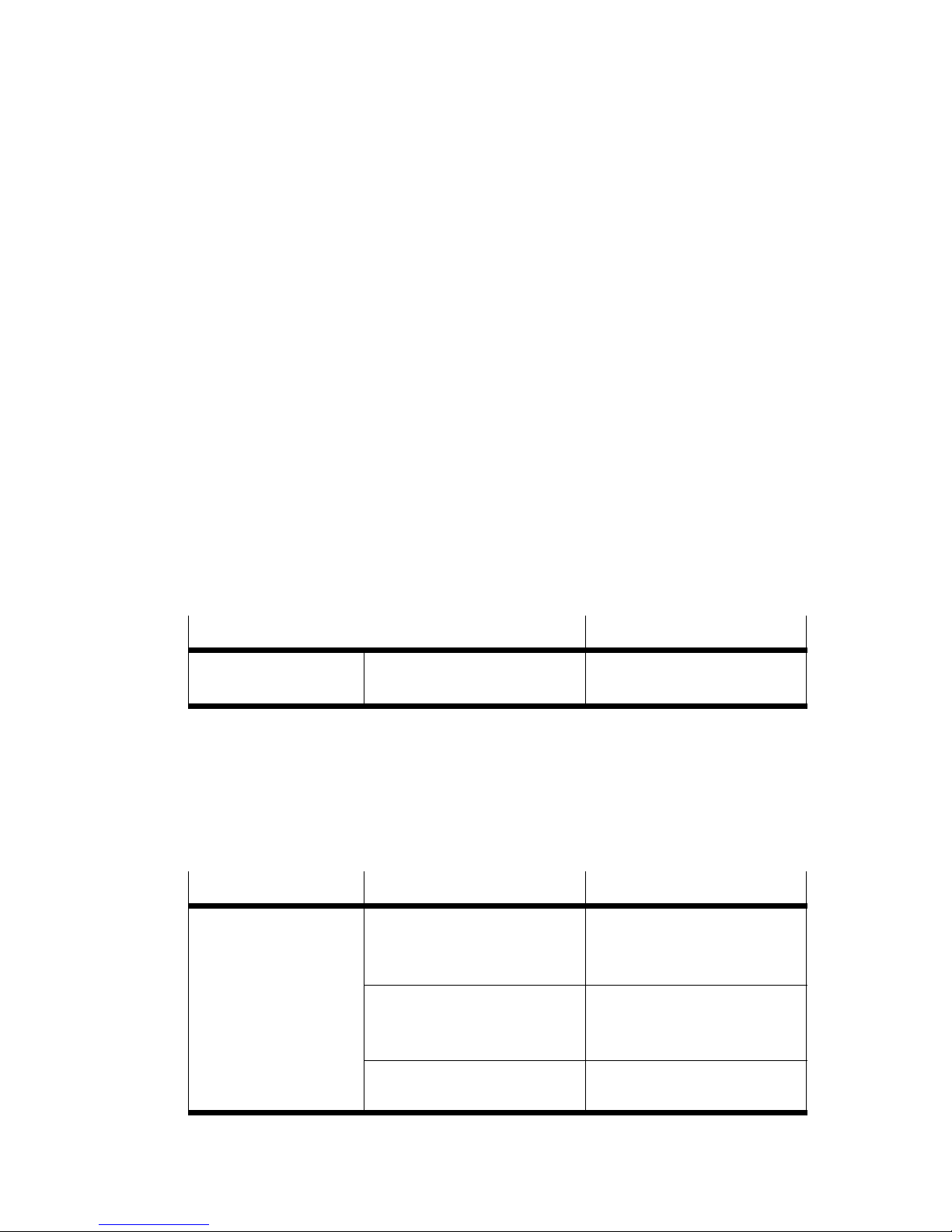
8 Zubehör
Bezeichnung Typ
Steckdosenkabel M8x1, 3−polig
M12x1, 4−polig
Bild11
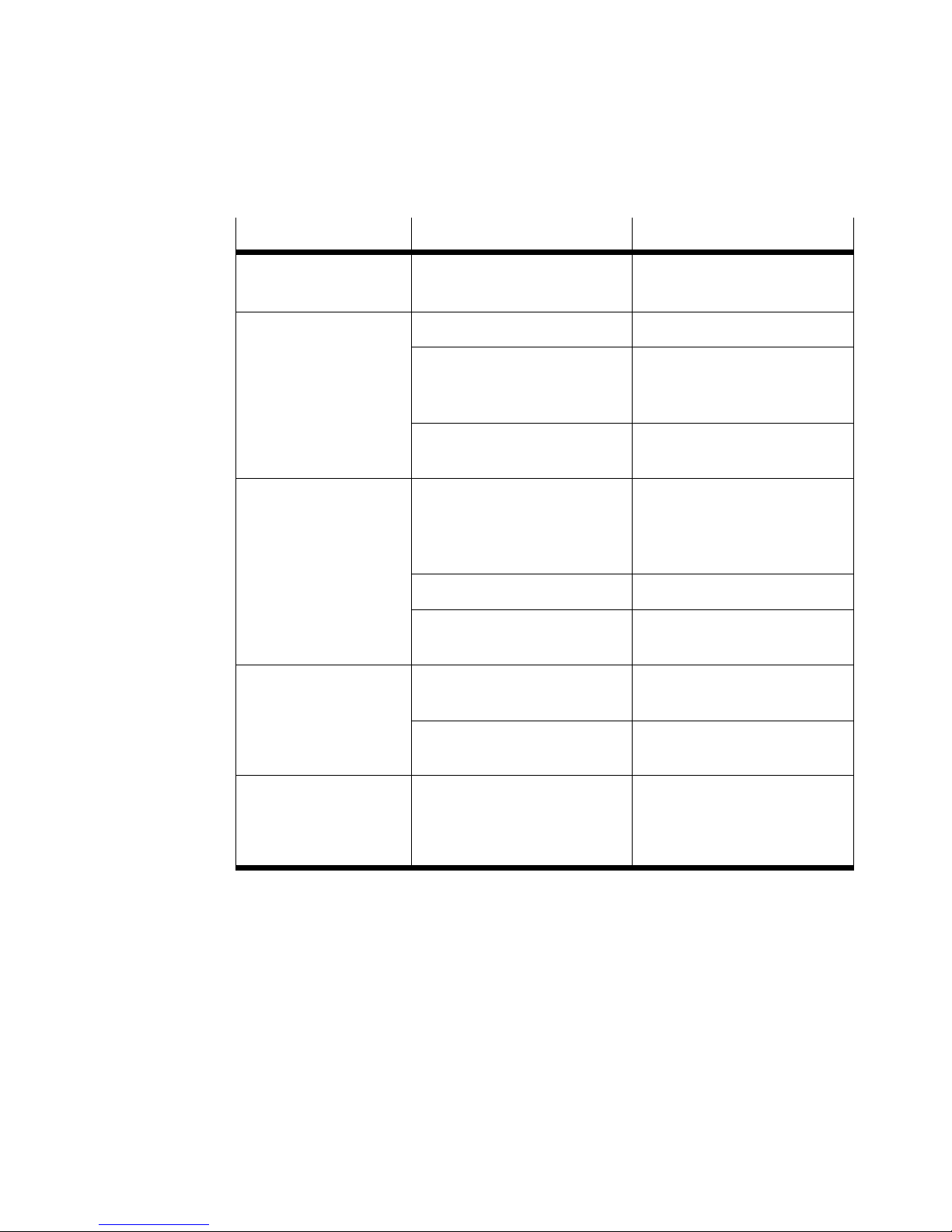
9 Störungsbeseitigung
Störung Mögliche Ursache Abhilfe
Keine Anzeige im
Display
Versorgungsspannung fehlt
oder keine zul. Betriebs−
spannung
Anschlüsse vertauscht
(verpolt)
SIM−M8−3Ū
SIM−M12−4Ū
Versorgungsspannung
einschalten / zul. Betriebs
spannungsbereich einhalten
MSŪ−LFM−Ū−DP/DN/DPI/DNI
gemäß Anschlussbild
verkabeln
20
MSŪ−LFM−Ū−DP/DN/DPI/DNI
defekt
Festo MSŪ−LFM−Ū−DP/DN/DPI/DNI 0611NH Deutsch
Kompletten Fein−/Feinstfilter
zu Festo senden
Page 21
MSŪ−LFM−Ū−DP/DN/DPI/DN I
Störung AbhilfeMögliche Ursache
Unvollständige
Anzeige im Display
Display defekt Kompletten Fein−/Feinstfilter
zu Festo senden
Druckanzeige blinkt Filterelement verschmutzt Filterpatrone wechseln
Durchflussbereich unzulässig Erlaubter Durchflussbereich
vom Fein−/Feinstfilter
beachten
Err" wird im Display
angezeigt (ermittelter
Basisdruck größer als
max. Basisdruck)
Durchfluss springt"
(nichtkonstant)
Durchfluss zu hoch (z.B.
beim Einschalten der Anlage)
Zeitkonstante Messwert
glättung erhöhen
Erlaubter Durchflussbereich
vom Fein−/Feinstfilter
beachten und erneut
Basisdruck ermitteln
Filterelement verschmutzt Filterpatrone wechseln
Ausgänge schalten
nicht entsprechend der
Fein−/Feinstfilter falsch
dimensioniert
Kurzschluss oder Überlast am
entsprechenden Ausgang
Fein−/Feinstfilter
austauschen
Kurzschluss/Überlast
beseitigen
vorgenommenen
Einstellungen
MSŪ−LFM−Ū−DP/DN/DPI/DNI
defekt
Kompletten Fein−/Feinstfilter
zu Festo senden
Einstellungen nicht
editierbar (lock" in
der Anzeige)
Bild12
Festo MSŪ−LFM−Ū−DP/DN/DPI/DNI 0611NH Deutsch
Zugriffsschutz aktiv Sicherheitscode eingeben
(wenn vergessen, Resetver
fahren laut Bedienung und
Betrieb")
21
Page 22
MSŪ−LFM−Ū−DP/DN/DPI/DN I
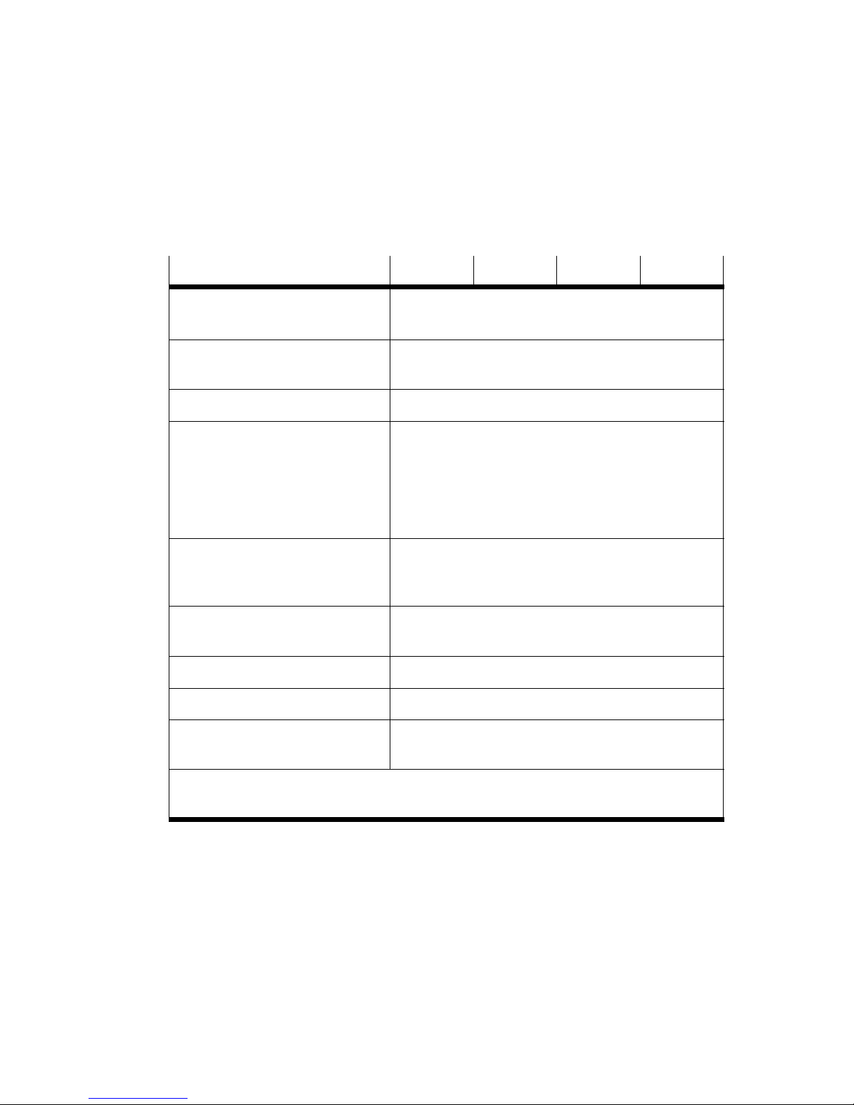
10 Technische Daten
MSŪ−LFM−Ū −DP −DN −DPI −DNI
Druckmessbereich
[bar] 0 Ū 1
1)
(Differenzdruck)
Eingangsdruck am Fein−/
[bar] Ţ 10
Feinstfilter MSŪ−LFM
Einbaulage senkrecht
Einstellbereich
Schaltdruck:
Hysterese:
Schaltdruck:
Hysterese:
Umgebungstemperatur
Mediumstemperatur
Lagertemperatur
Betriebsspannungs
[%]
[%]
[bar]
[bar]
[°C]
[°C]
[°C]
0 Ū 100
0 Ū 100
0,020 Ū 0,998
0 Ū 0,9
1)
0 Ū +50
0 Ū +50
0 Ū +50
1)
[VDC] 15Ū30 (zul. Restwelligkeit max. 10%)
bereich
Leerlaufstrom [mA] max. 45 (ca. 40 typ.)
Bereitschaftsverzögerung [ms] max. 450 (mit Einschaltfehlimpulsunterdrückung)
Max. zul.
Signalleitungslänge
1)
Werte für die Einheiten kPa und psi" müssen mit den entsprechenden Faktoren
umgerechnet werden.
Bild13
22
[m] 30
Festo MSŪ−LFM−Ū−DP/DN/DPI/DNI 0611NH Deutsch
Page 23
MSŪ−LFM−Ū−DP/DN/DPI/DN I
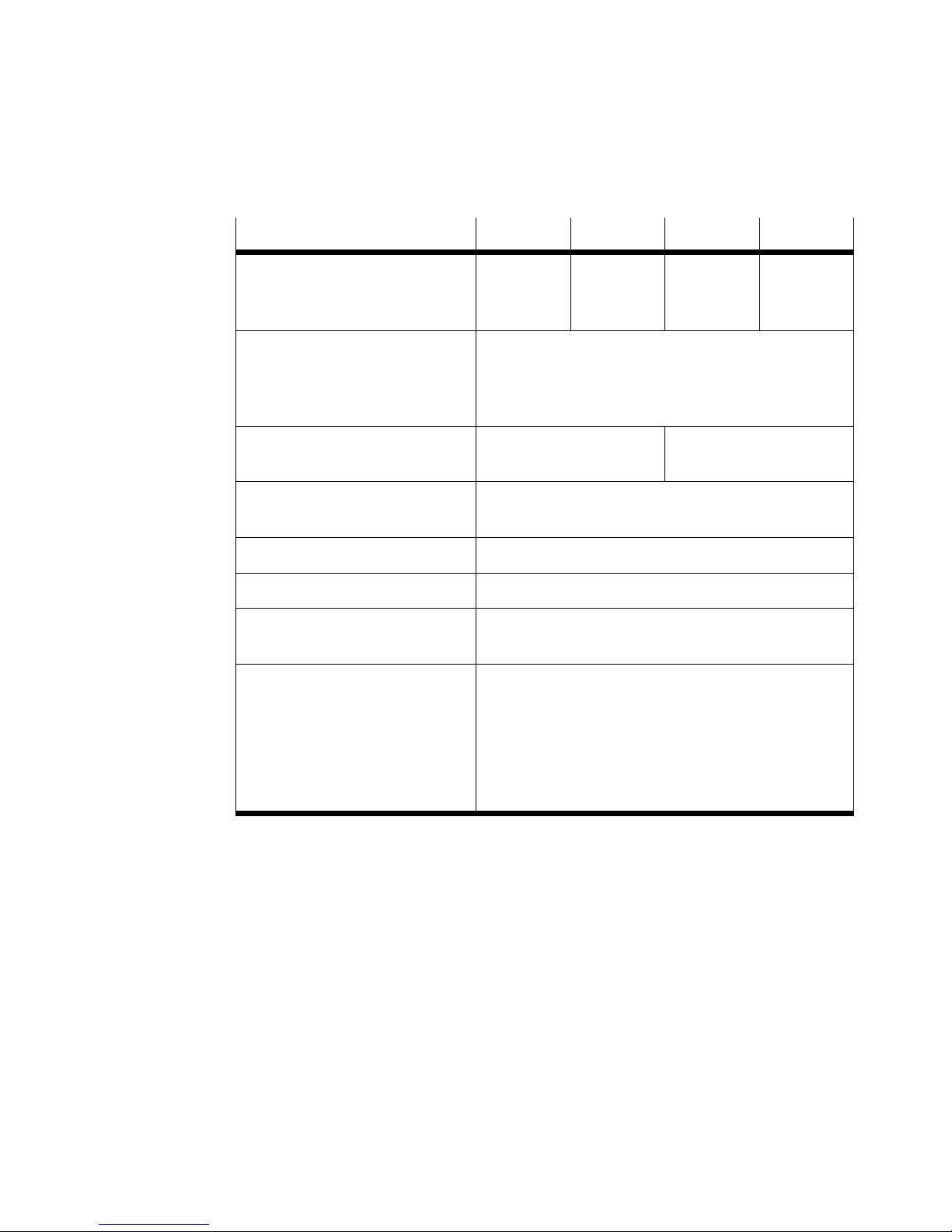
MSŪ−LFM−Ū −DP −DN −DPI −DNI
Schaltausgänge Plus−
schaltend
(PNP)
Zul. Schaltstrom
Schaltbare Kapazität
Induktionsschutz
Schaltzeiten (ein/aus)
Analogausgang (Strom)
Zul. Lastwiderstand
Kurzschlussfestigkeit
Verpolungsschutz
[mA]
[nF]
[ms]
[mA]
[]
max. 150
max. 100
angepasst auf MZ−, MY−, ME−Spulen
max. 10 (5 typ.)
4 Ū 20
taktend
für alle elektrischen Anschlüsse
Null−
schaltend
(NPN)
Schutzart IP65 (nach EN 60529)
Schutzklasse III (nach DIN VDE 0106−1)
Störfestigkeit
Störaussendung
siehe Konformitätserklärung (www.festo.com)
siehe Konformitätserklärung (www.festo.com)
Werkstoffe
Gehäuse
MS−Adapter
Tasten
Display
Dichtungen
Stecker
Polyamid, Polyacetal (verstärkt)
Polyamid (verstärkt)
Nitrilkautschuk
Polycarbonat
Nitrilkautschuk
Messing
Plus−
schaltend
(PNP)
max. 300
Null−
schaltend
(NPN)
Bild14
Festo MSŪ−LFM−Ū−DP/DN/DPI/DNI 0611NH Deutsch
23
Page 24
MSŪ−LFM−Ū−DP/DN/DPI/DN I
11 Menüstruktur
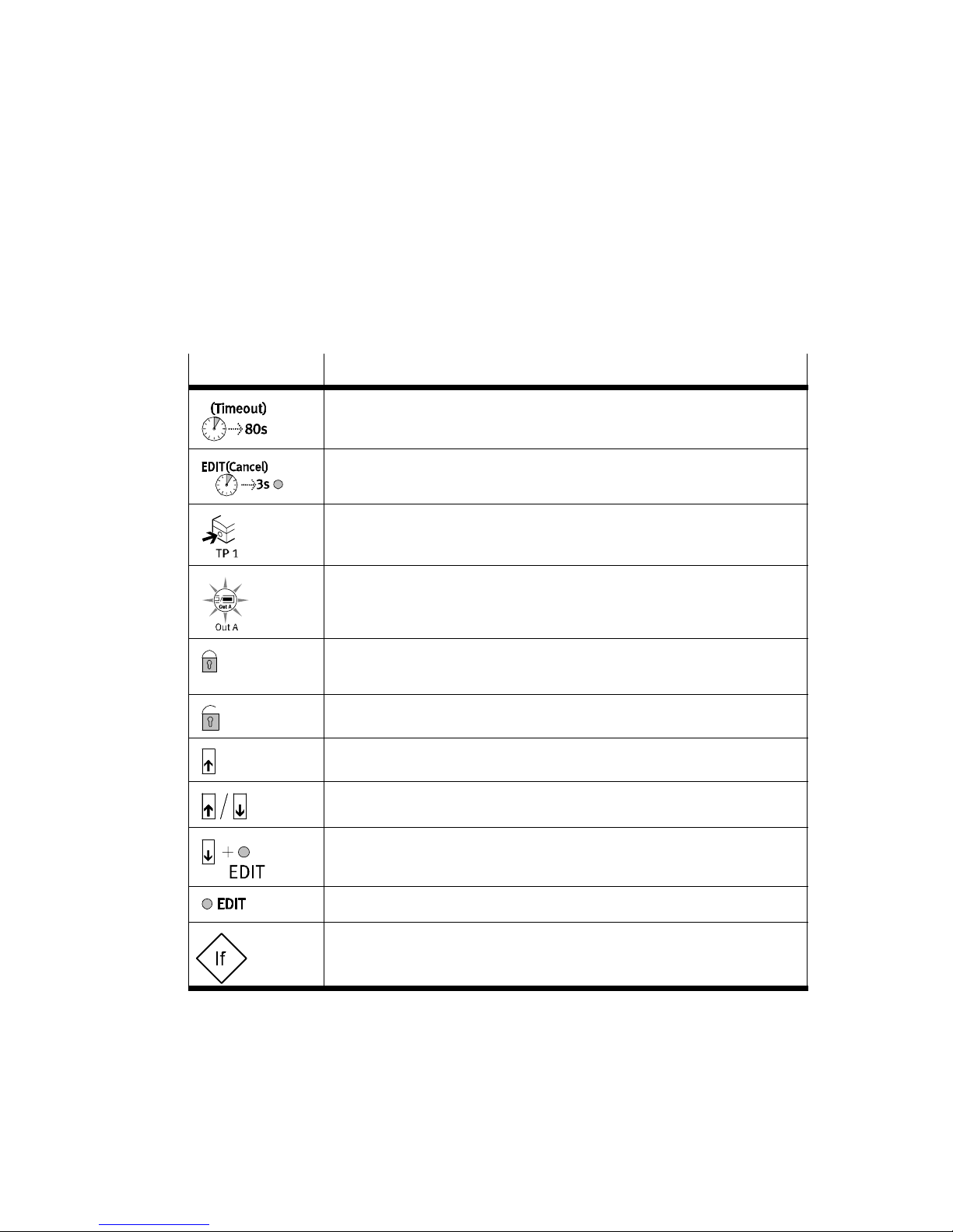
Symbolik zur Darstellung der Menüstruktur
Symbol
Bedeutung
Automatische Rückkehr in den Grundzustand (RUN−Modus) nach
Ablauf der Überwachungszeit (hier 80 Sekunden)
Um manuell in den Grundzustand (RUN−Modus) zurückzukehren,
3Sekunden EDIT−Knopf drücken
Druck erzeugen (zum Teachen des Basisdrucks)
Symbol auf dem Display blinkt (hier Out A)
Sicherheitscode aktiv
(lock Sperrung gegen unbefugte Programmierung)
Sicherheitscode inaktiv
Taste (hier UP−Taste) drücken
UP−Taste oder DOWN−Taste drücken
Bild15
24
DOWN−Taste und EDIT−Knopf gleichzeitig drücken
EDIT−Knopf kurz drücken
Verzweigung im Menüsystem
Festo MSŪ−LFM−Ū−DP/DN/DPI/DNI 0611NH Deutsch
Page 25
MSŪ−LFM−Ū−DP/DN/DPI/DN I
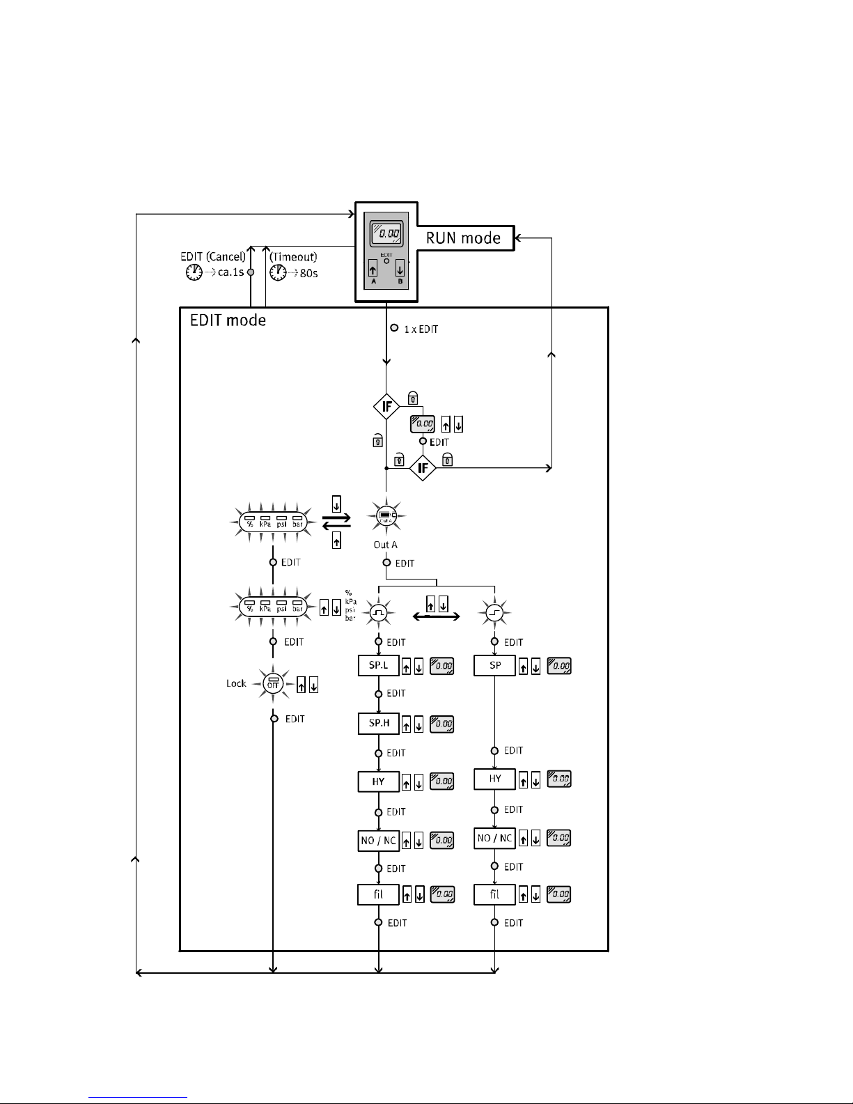
Bild16: EDIT−Modus
Festo MSŪ−LFM−Ū−DP/DN/DPI/DNI 0611NH Deutsch
25
Page 26
MSŪ−LFM−Ū−DP/DN/DPI/DN I
Bild17: SHOW−Modus
26
Festo MSŪ−LFM−Ū−DP/DN/DPI/DNI 0611NH Deutsch
Page 27
MSŪ−LFM−Ū−DP/DN/DPI/DN I
Bild18: TEACH−Modus (nur bei eingestellter Einheit %" möglich)
Festo MSŪ−LFM−Ū−DP/DN/DPI/DNI 0611NH Deutsch
27
Page 28

MSŪ−LFM−Ū−DP/DN/DPI/DN I
28
Festo MSŪ−LFM−Ū−DP/DN/DPI/DNI 0611NH Deutsch
Page 29

MSŪ−LFM−Ū−DP/DN/DPI/DN I
Filter contamination recognition with display
MS...LFM−...−DP/DN/DPI/DNIEnglish
Contents
1 Operating elements and connections 30 . . . . . . . . . . . . . . . . . . . . . . . . . . . .
2Function and application 31 . . . .
3 Conditions of use33 . . . . . . . . .
4 Fitting 33 . . . . . . . . . . . . .
Fitting mechanical/pneumatic components 33 . . . . . .
Electrical installation 34 . . . . . . . . . . . . . . . . . . . . . . . . . . . . . . .
5 Commissioning 36 . . . . . . . . . . . . . . . . . . . . . . . . . . . . . . . . . .
Symbols on the display 36 . . . . . . . . . . . . . . . . . . . . . . . . . . . . . . . . . .
Fast commissioning with factory setting 38 . . . . . . . . . . . . . . . . . . . . . . . . . . .
6 Operation 39 . . . . . . . .
RUN mode 39 . . . . . .
SHOW mode 40 . . .
EDIT mode 40 . . .
TEACH mode
Instructions for faultless operation 45 . . . . . . . . . . . . . . . . . . .
Resetting the device to the factory setting 45 . . . . . . . . . . . . . . . . . . . . . . . . .
7 Care and maintenan
. . . . . . . . . . . . . . . . . . . . . . . . . . . . . . . . . . . . . . . . . . . . . . . .
(only possible with set unit %") 44 . . . . . . . . . . . . . . . . . . . . . .
. . . . . . . . . . . . . . . . . . . . . . . . . . . . . . . . . . . . . . . . .
. . . . . . . . . . . . . . . . . . . . . . . . . . . . . . . . . . . . . . . . . . .
. . . . . . . . . . . . . . . . . . . . . . . . . . . . . . . . . . . . . . . . . . . . .
. . . . . . . . . . . . . . . . . . . . . . . . . . . . . . . . . . . . . . . . . . . . . .
ce46 . . . . . . . . . . . . . . . . . . . . . . . . . . . . . . . . . . . . . . . . .
. . . . . . . . . . . . . . . . . . . . . . . . . . . . . . . . . . .
. . . . . . . . . . . . . . . . . . . . . . . . . . . . . . . . . . . .
. . . . . . . . . . . . . . . . . .
. . . . . . . . . . .
. . . . . . . . . . . . .
. . . . . . . . . . . .
. . . . . . .
8 Accessories 46 . . . .
9 Eliminating fau
10 Technical s
11 Menu structure 50 . .
Festo MSŪ−LFM−Ū−DP/DN/DPI/DNI 0611NH English
. . . . . . . . . . . . . . . . . . . . . . . . . . . . . . . . . . . . . . . . . . . . . .
lts 46 . . . . . . . . . . . . . . . . . . . . . . . . . . . . . . . . . . . . . . . . . . . . .
pecifications 48 . . . . . . . . . . . . . . . . . . . . . . . . . . . . . . . . . . . . . . .
. . . . . . . . . . . . . . . . . . . . . . . . . . . . . . . . . . . . . . . . . . . . .
29
Page 30
MSŪ−LFM−Ū−DP/DN/DPI/DN I
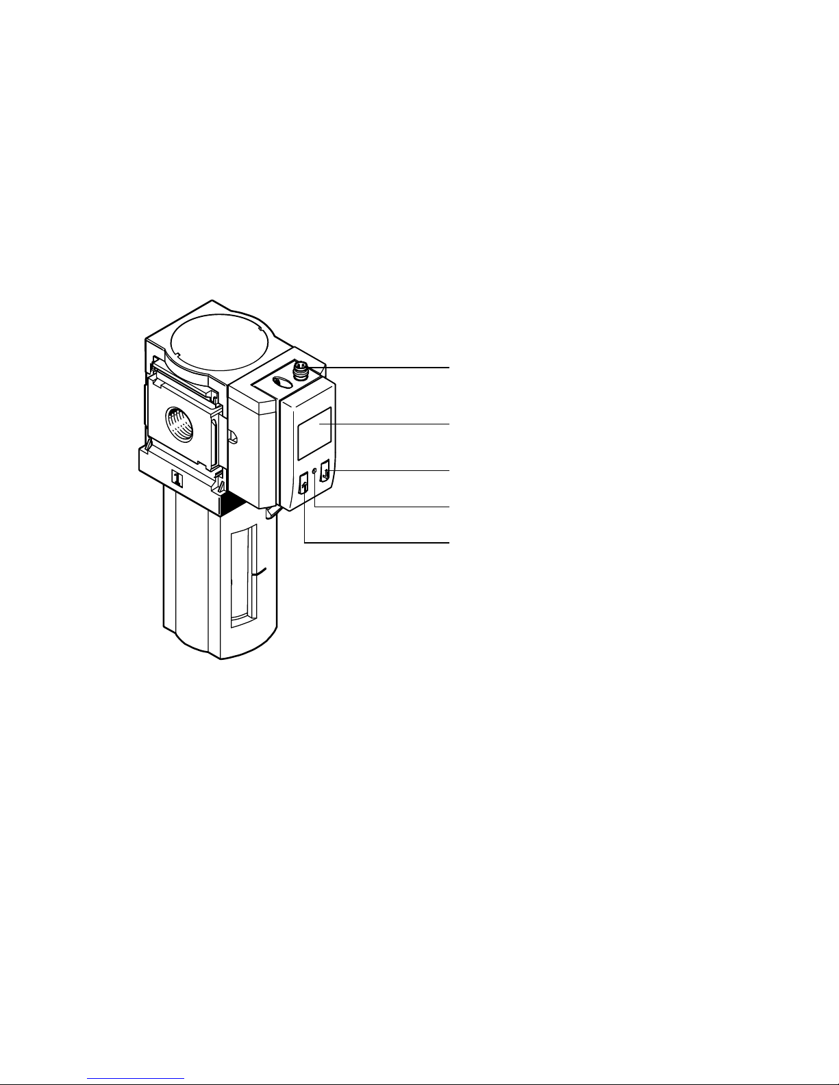
1 Operating elements and connections
Fine/micro filter MSŪ−LFM with filter contamination recognition with display
MSŪ−LFM−Ū−DP/DN/DPI/DN I
1
2
3
1 Electrical connection
(design depends on type)
2 Display
Fig.1
4
5
3 DOWN button
4 EDIT button
5 UP button
30
Festo MSŪ−LFM−Ū−DP/DN/DPI/DNI 0611NH English
Page 31

MSŪ−LFM−Ū−DP/DN/DPI/DN I
2 Function and application
The filter contamination recognition with display MSŪ−LFM−Ū−DP/DN/DPI/DNI has
been designed for monitoring the degree of contamination in the fine/micro filter
MSŪ−LFM. The degree of contamination is derived from the continuous measure
ment of the differential pressure which increases with rising contamination.
Measurements are carried out using a piezoresistive sensor element
ing electronic evaluation unit. The measurement result is shown numerically on the
display. Connection to higher−order systems is carried out via a switching output.
The switching point for the filter cartridge replacement is adjustable.
The switching outputs can be configured as nc" and no" contacts. The desired
switching points can
The product designs MSŪ−LFM−Ū−DPI/DNI also offer an analogue output which
passes the measured differential pressure on as an electric pressure−proportional
signal.
be defined as threshold comparator or window comparator.
with a follow
Term
Differential
pressure
Maximum
pressure
Basic pressure Medium value of all measured differential pressure values in a
Max. basic
pressure
Explanation
Pressure drop in the fine/micro filter MSŪ−LFM between the input
and the output. The differential pressure depends on the flow and on
the degree of contamination.
350mbar
Fixed end value for the differential pressure in the unit %". The
value corresponds to 100%. We recommmend that you replace the
filter cartridge when this value is reached.
particular time interval. The basic pressure is the starting pressure
for the filter contamination recognition in percent display
(0% contamination corresponds to new filter status).
The basic pressure must be ascertained in order that the filter
contamination reognition can be carried out faultlessly. A new filter
indicates a particular pressure drop which must not be recognized as
a degree of filter contamination.
300mbar
The basic pressure ascertained must be lower than the max. basic
pressure, otherwise an error will be shown in the display.
Festo MSŪ−LFM−Ū−DP/DN/DPI/DNI 0611NH English
31
Page 32

MSŪ−LFM−Ū−DP/DN/DPI/DN I
Term Explanation
Time−constant
measured value
smoothing
1s, 5s, 20s
Selectable time window for the measured value smoothing. The last
measured differential pressure values within this time window will
be used for forming medium values. The weighting of individual error
measurements (e.g. by flow fluctuations) will be reduced with a
larger time window. The smoothed medium value will be shown on
the display and defines the status of the switching output.
Note on the product designs MSŪ−LFM−Ū−DPI/DNI with analogue
output:
The measured value smoothing has no effect on the signal at the
analogue output. The signal is output without smoothing.
Unit %, bar, kPa, psi
Shows the smoothed differential medium value in the relevant unit.
Peculiarities with unit %":
S Rough grading in 5 % steps, without 5%, 10% and 15%, i.e.
0%, 20%, 25%, Ū , 100%
S Values greater than 100% cannot be displayed if the differential
pressure rises above 350mbar (maximum pressure).
The display 100% flashes on the screen.
Switching
threshold /
switching point
Adjustable switching pressure If the smoothed differential pressure
medium value reaches the switching point, a signal will be output at
the switching output (è Fig.10).
Hysteresis Adjustable delay in resetting the switching output to its original
Fig.2
32
defined status (è Fig.10).
Festo MSŪ−LFM−Ū−DP/DN/DPI/DNI 0611NH English
Page 33
MSŪ−LFM−Ū−DP/DN/DPI/DN I
3 Conditions of use
Please note
Incorrect handling can result in malfunctioning.
S Make sure that the following specifications are always observed.
S Compare the maximum values specified in these operating instructions with
your actual application (e.g. operating media, pressures, forces, torques,
temperatures, masses, speeds, voltages).
S Take into consideration the ambient conditions at the location of use.
S Please
S Remove all transport packing such as protective wax, foils (polyamide), caps
(polyethylene), cardboard boxes.
It is intended that the packaging be recycled on the basis of its constituent
materials (exception: oiled paper = other waste).
S Use the product in its original state. Unauthorized
permitted.
4 Fitting
Fitting mechanical/pneumatic components
The filter contamination recognition with display MSŪ−LFM−Ū−DP/DN/DPI/DNI is
fitted onto the fine/micro filter MSŪ−LFM at the factory. Mounting work is not
required.
comply with national and local safety laws and regulations.
modification is not
Festo MSŪ−LFM−Ū−DP/DN/DPI/DNI 0611NH English
33
Page 34
MSŪ−LFM−Ū−DP/DN/DPI/DN I
Electrical installation
Warning
S Use only power units which guarantee reliable electrical isolation of the
operating voltage as per IEC/DIN EN 60204−1. Observe also the general
requirements for PELV power circuits as per IEC/DIN EN 60204−1.
Please note
Long signal cables reduce the immunity to interference.
S Make sure that the signal cables are not longer than 30 m.
S Wire the device as follows:
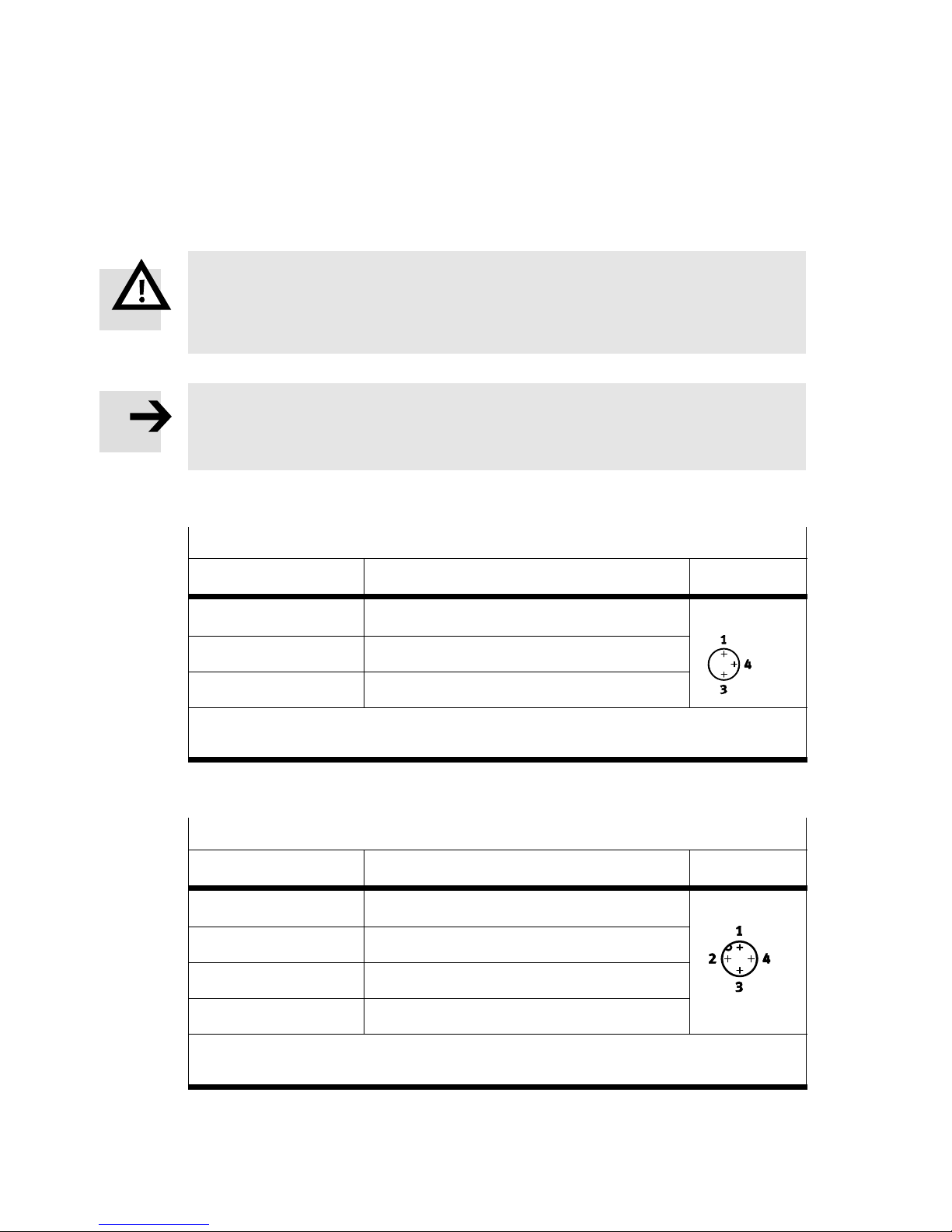
MSŪ−LFM−Ū−DP/DN−Ū (1 switching output)
Pin / cable colours
1)
Assignment of M8x1, 3−pin Plug
1 / brown (BN) +24VDC supply voltage M8x1, 3−pin
4 / black (BK) Output A (Out A)
3 / blue (BU) 0 V
1)
If using the cable with socket as per accessories.
2)
Tightening torque: max. 0.3Nm
Fig.3
2)
MSŪ−LFM−Ū−DPI/DNI−Ū (1 switching output and 1 analogue output)
Pin / cable colours
1)
Assignment of M12x1, 4−pin Plug
1 / brown (BN) +24VDC supply voltage M12x1, 4−pin
2 / white (WH) Output A (Out A)
3 / blue (BU) 0 V
2)
4 / black (BK) Analogue output 4Ū20mA
1)
If using the cable with socket as per accessories.
2)
Tightening torque: max. 0.5Nm
Fig.4
34
Festo MSŪ−LFM−Ū−DP/DN/DPI/DNI 0611NH English
Page 35
MSŪ−LFM−Ū−DP/DN/DPI/DN I
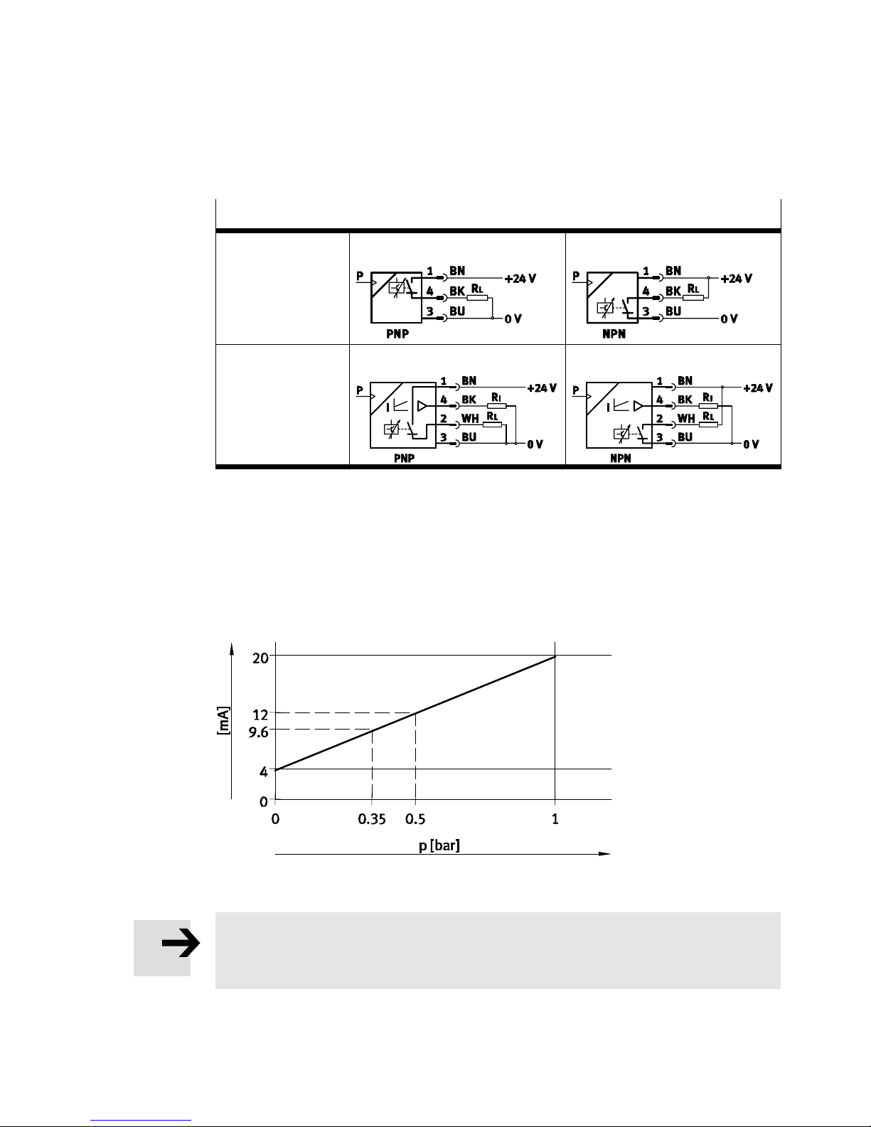
Circuit diagrams
1 switching output MSŪ−LFM−Ū−DP−Ū MSŪ−LFM−Ū−DN−Ū
1switching output
and
1analogue output
Fig.5
MSŪ−LFM−Ū−DPI−Ū MSŪ−LFM−Ū−DNI−Ū
Analogue output (only with MSŪ−LFM−Ū−DPI/DNI)
The differential pressure measured value lies at the analogue output as an
electrric pressure−proportional signal, i.e. the pressure measuring range 0Ū1bar
corresponds to an electric signal in the range 4Ū20mA.
Fig.6
Please note
The measured value smoothing has no effect on the signal at the analogue
output. The signal is output without smoothing.
Festo MSŪ−LFM−Ū−DP/DN/DPI/DNI 0611NH English
35
Page 36
MSŪ−LFM−Ū−DP/DN/DPI/DN I
5 Commissioning
Symbols on the display
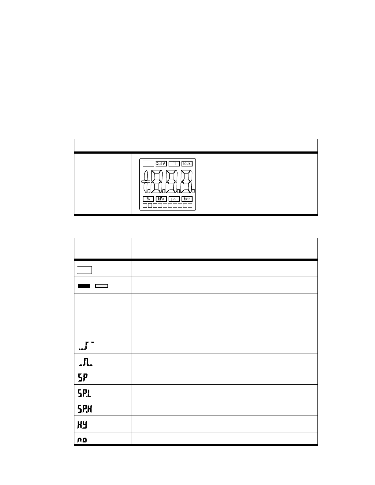
LCD display
Display, optimized
for reading
Fig.7
Symbols on the
Description
display
Out A
/
[fil] Flashes when the time constant measured value smoothing is
[lock] Lights up when security lock is active
Switching output A
Switching output set / not set
entered
(locked against unauthorized programming)
Threshold comparator
Window comparator
Switching pressure
Lower switching pressure
36
Upper switching pressure
Hysteresis
Normally open contact
Festo MSŪ−LFM−Ū−DP/DN/DPI/DNI 0611NH English
Page 37
MSŪ−LFM−Ū−DP/DN/DPI/DN I
Symbols on the
display
Description
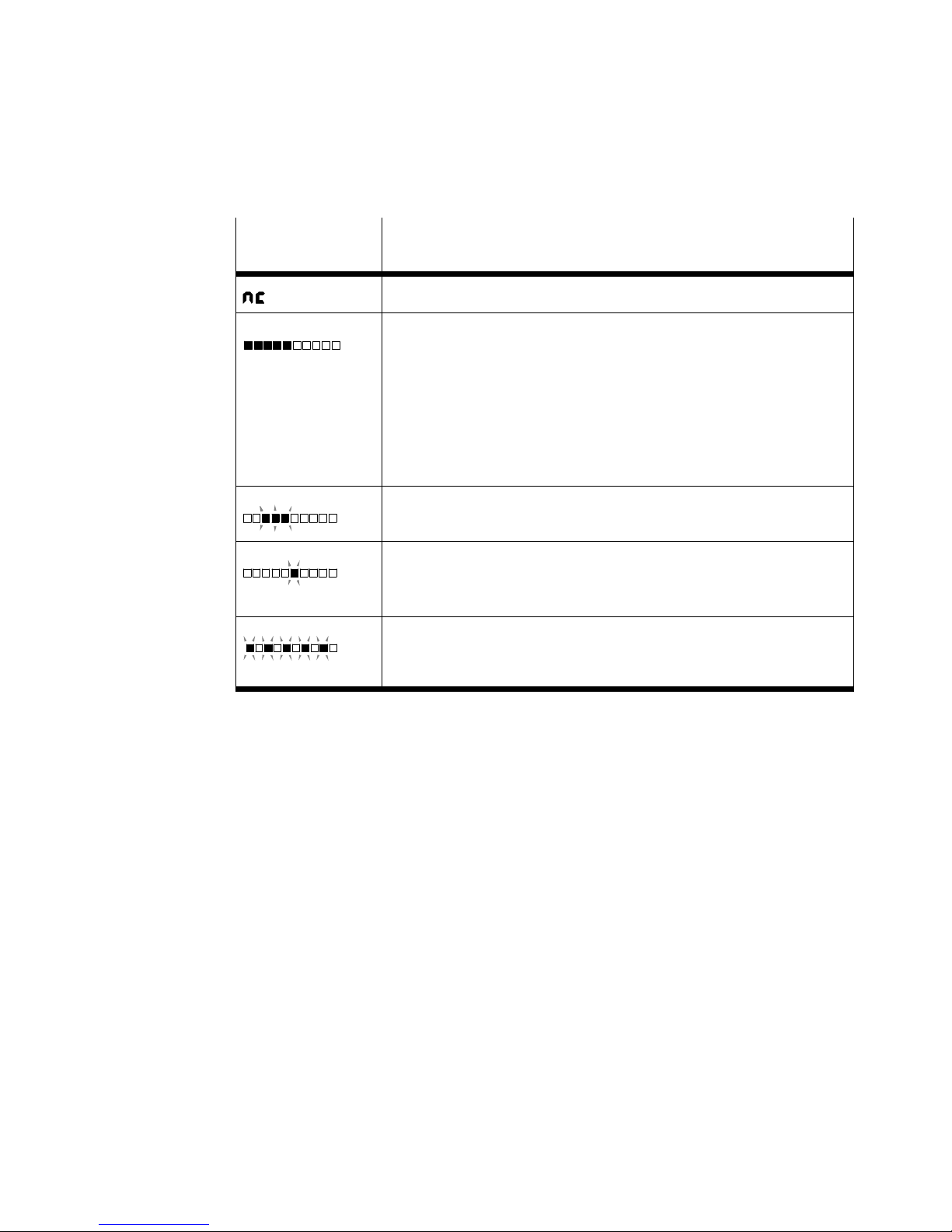
Normally closed contact
Segments light up: Graphic display of the current differential
pressure medium value in relation to the maximum value of the
measuring range, i.e.
S with the unit bar" the bar represents the range 0 to 1 bar
(corresponding values with units kPa" and psi")
S with the unit %" the bar represents the range 0% to 100%.
In contrast to the number display, the bar display also
represents values between 0% and 20%.
3 segments flashing:
hysteresis value is displayed
1 segment flashing − the following is shown:
segment 5: switching point SP or SP.L
segment 8: switching point SP.H
5 segments flashing:
basic pressure is shown in the SHOW mode or in the TEACH
mode.
Fig.8
Festo MSŪ−LFM−Ū−DP/DN/DPI/DNI 0611NH English
37
Page 38

MSŪ−LFM−Ū−DP/DN/DPI/DN I
Fast commissioning with factory setting
The filter contamination recognition with display MSŪ−LFM−Ū−DP/DN/DPI/DNI is
supplied from the factory with the following setting:
Factory setting
Unit %
Switching threshold / switching point [%] 100
Switching behaviour threshold comparator
Switching characteristic no (normally open contact)
Hysteresis [%] 5
Basic pressure [mbar] 20
Time−constant measured value
smoothing
1)
corresponds to a differential pressure of 350mbar (max. pressure)
Fig.9
[s] 1
1)
After fitting the new fine/micro filter MSŪ−LFM into your system, ascertain the basic
pressure (only possible with set unit %"):
1. Switch on the operating voltage for the filter contamination recognition with
display MSŪ−LFM−Ū−DP/DN/DPI/DNI.
The device is automatically in the RUN mode (basic setting). If you are not sure
whether the
device is in the RU N mode, hold the EDIT button pressed down for
1s. The device is then in the RUN mode.
2. Commissioning the system
Wait until pressure fluctuations in your system have been reduced to a
minimum.
3. In order to start the measurement, press first the DOWN button, then also the
EDIT button.
5 segments in the bar display flash. The differential pressure is measured
continuously. If the measurement is not concluded after max. 15 minutes, the
device will return to the RUN mode without modification.
4. In order to conclude the measurement, press the DOWN button again, then
also the EDIT button.
The device is then
38
in the RUN mode again.
Festo MSŪ−LFM−Ū−DP/DN/DPI/DNI 0611NH English
Page 39
MSŪ−LFM−Ū−DP/DN/DPI/DN I
The basic pressure is calculated from the differential pressure values measured
and saved. The display shows 0% contamination. If there is an error, Err" will
be shown (è section 9, Eliminating faults).
During operation the filter will become contaminated. The rising percent
number indicates the degree of contamination.
If the differential pressure exceeds
pressure), a flashing degree of contamination of 100% will be shown on the
display. At the same time a signal will be supplied at the switching output.
The filter cartridge should now be replaced.
Please note
When the filter cartridge has been replaced, the basic pressure must be ascer
tained again. The basic pressure must be ascertained again only if the condi
tions of use for the fine/micro filter have been modified (e.g. if it is fitted in a
new system or if modifications have been made
6 Operation
Requirement:
S The device must be switched on.
Please note
An overview of the menu structure can be found in section 11.
the threshold of 350mbar (maximum
to the compressed air system).
RUN mode
The degree of contamination of the filter (smoothed differential pressure medium
value), the set unit and the signal status of switching output Out A will be displayed
in the RUN mode. A flashing value indicates that the
exceeded.
The RUN mode can be accessed from other modes as follows:
by pressing the EDIT button for 1s
when a monitoring period expires (Timeout è section 11, Menu structure).
Festo MSŪ−LFM−Ū−DP/DN/DPI/DNI 0611NH English
measuring range has been
39
Page 40
MSŪ−LFM−Ū−DP/DN/DPI/DN I
SHOW mode
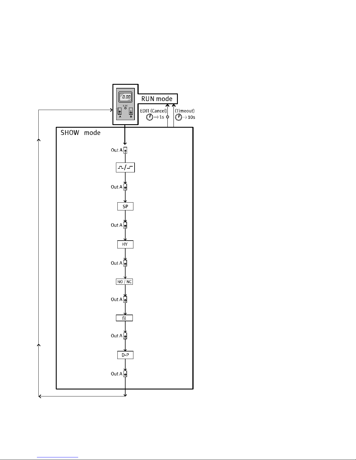
If the device is in the RUN mode, the SHOW mode will become active when the
UPbutton is pressed. Each time the UP button is pressed, the current settings of
the switching output will be displayed one after the other. After switching through
all the values, the unit then returns
The following settings and values will be displayed:
the switching function [Threshold value or window comparator]
the switching points [SP] or [SP.L] and [SP.H]
the hysteresis [HY]
the switching characteristics [no/nc]
the time−constant measured value smoothing [fil]
to the RUN mode.
the basic pressure [D−P].
Note on the unit set [%]:
A flashing value of
100% at a switching point means that a value greater than the
maximum pressure (350mbar) has been selected. The higher value has been set in
the unit bar", kPA" oder psi". In this case check your settings.
EDIT mode
Please note
First ascertain the basic pressure (èTEACH mode), before carrying out settings
in the EDIT mode.
The following settings can be undertaken in the EDIT mode:
the switching function [Threshold value or window comparator]
the switching points [SP] or [SP.L] and [SP.H]
the hysteresis [HY]
the switching characteistic [no/nc]
the time−constant measured value
the unit of measurement (%, kPA, psi, bar) and security code (lock).
40
smoothing [fil]
Festo MSŪ−LFM−Ū−DP/DN/DPI/DNI 0611NH English
Page 41
MSŪ−LFM−Ū−DP/DN/DPI/DN I
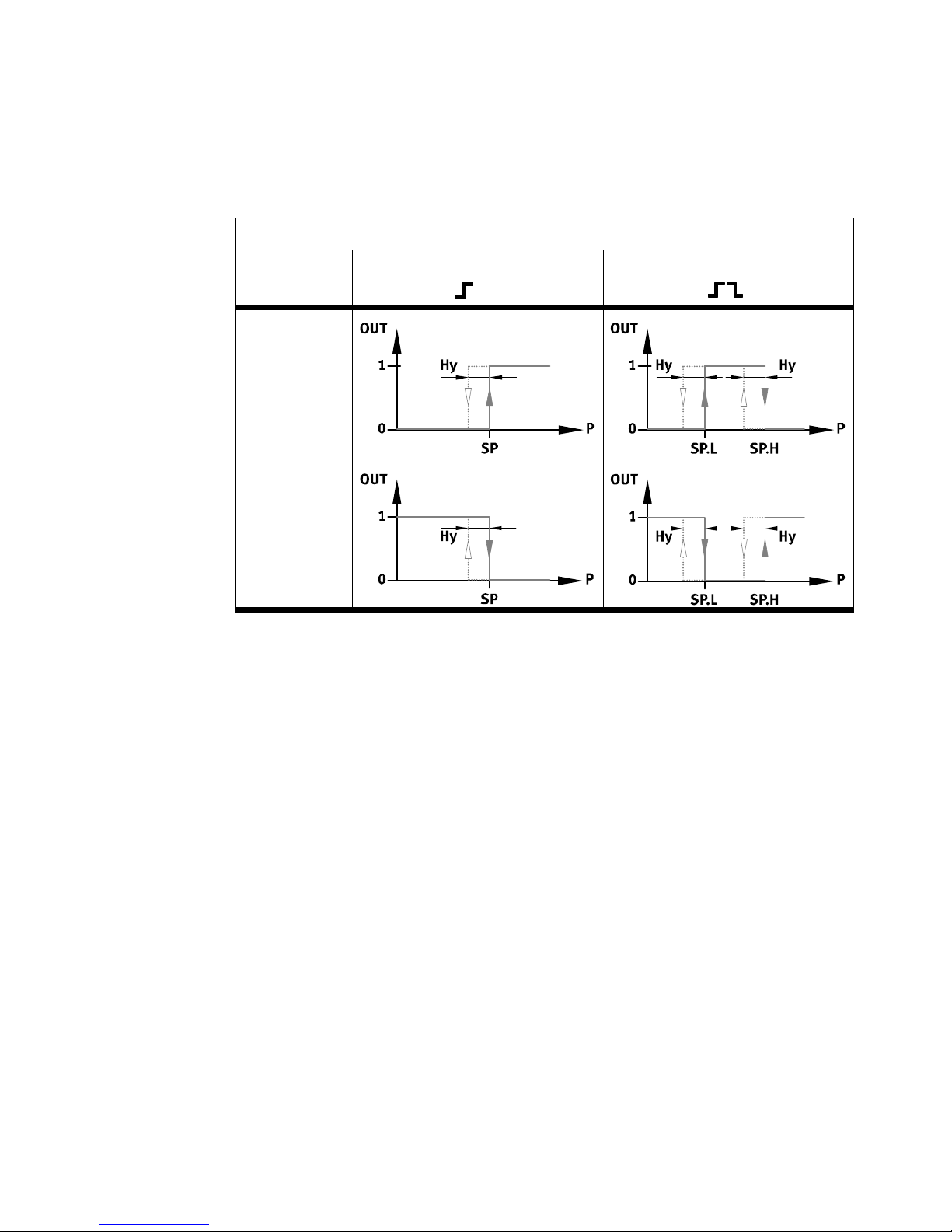
Overview oif switching points (SPŪ) and hysteresis (Hy)
With setting
no" (normally
open contact)
With setting
nc" (normally
closed contact)
Threshold comparator setting With the window comparator
setting
Fig.10
Notes:
If the switching function is changed, the switching points must be checked
and, if necessary, reset.
The value 100% can be set in the unit % both for the hysteresis and the
switching point. The value 100% corresponds with the switching point to a
value of 350mbar (maximum pressure), with the hysteresis
to a value of
330mbar.
Festo MSŪ−LFM−Ū−DP/DN/DPI/DNI 0611NH English
41
Page 42
MSŪ−LFM−Ū−DP/DN/DPI/DN I
Setting the switching behaviour of the switching outputs
Please note
In the EDIT mode modifications will become effective immediately and can
affect the switching behaviour of the switching output.
S Activate the password protection (security code) in order to prevent
unintentional modification by unauthorised third parties.
S Carry out the following steps:
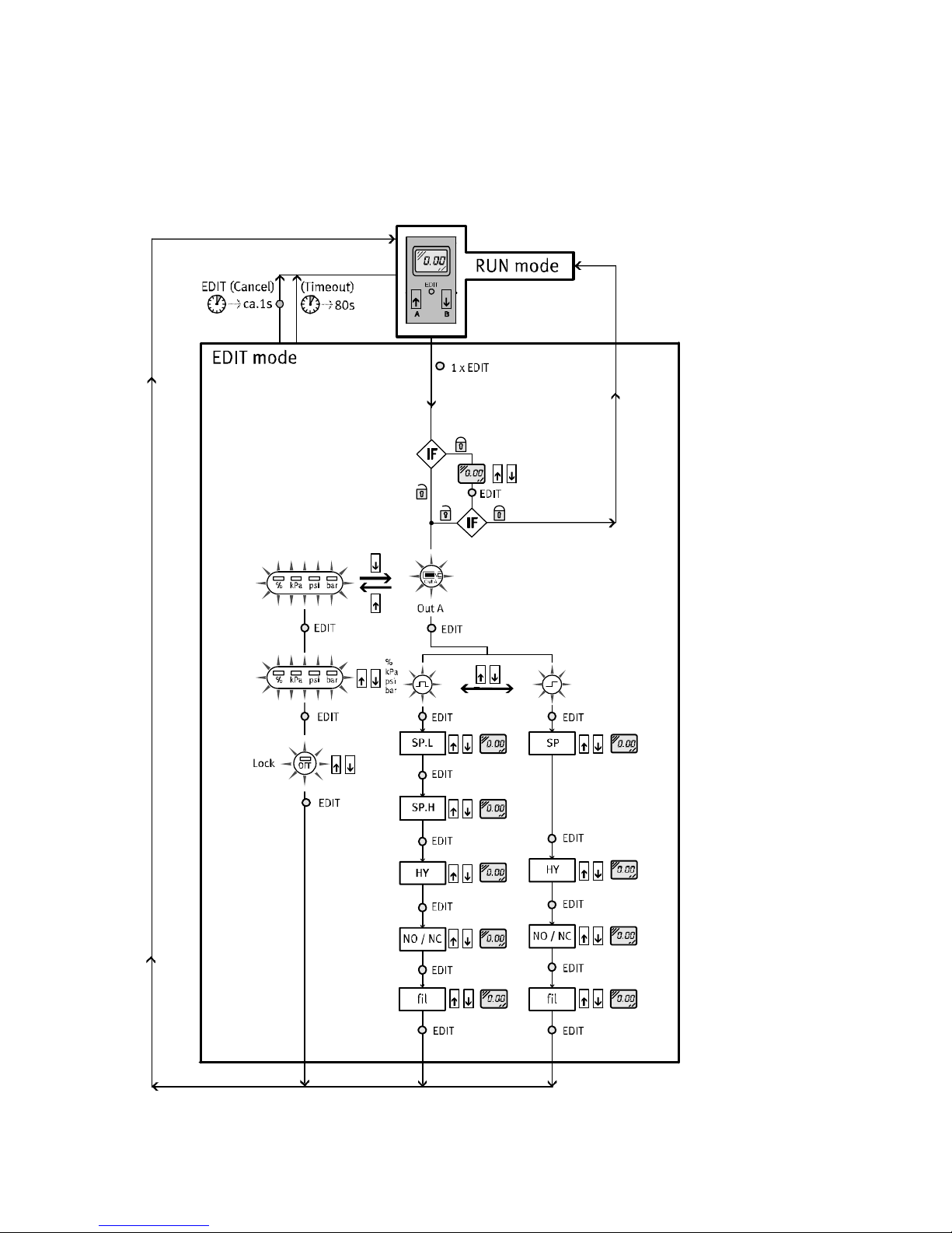
1. In order to activate the EDIT mode, press the EDIT button.
Only with active security locking [lock] flashes:
2. Press the UP/DOWN button until the desired security code is set.
3. Press the EDIT button.
If the entry is correct, the security lock will be released.
If the entry is incorrect, the security lock will remain active and the device
will return to the RUN
mode.
[Out A] flashes.
4. Select with the UP/DOWN button between
setting the switching functions [Out A] flashes
or
setting the unit and the security code [%], [kPA], [psi], [bar] and [lock]
flashes.
5. In order to confirm the selected setting mode. press the EDIT button.
è Setting the switching functions
è Setting the unit
and the security code
Setting the switching functions
The currently set switching function flashes.
1. Select desired switching function (threshold value/window comparator) with
the UP/DOWN button.
2. In order to confirm, press the EDIT button.
[SP] or [SP.L] is shown briefly. Segment 5 of the bar display flashes.
42
Festo MSŪ−LFM−Ū−DP/DN/DPI/DNI 0611NH English
Page 43
MSŪ−LFM−Ū−DP/DN/DPI/DN I
3. Set the switching point (SP or SP.L) with the UP/DOW N button.
4. In order to confirm, press the EDIT button.
With switching function Window Comparator:
[SP.H] is shown briefly. Segment 8 of the bar display flashes.
5. Set the value (SP.H) with the UP/DOWN button.
SP.H lies above SP.L up to the end value in
6. In order to confirm, press the EDIT button.
[HY] is shown briefly. 3 segments of the bar display flash.
7. Set the hysteresis (HY) with the UP/DOWN button.
8. In order to confirm, press the EDIT button.
the setting range.
[no] or [nc] flashes.
9. Set the switching characteristic [no/nc] with the UP/DOWN button.
10. In order to
confirm, press the EDIT button.
[fil] flashes.
11. Set the time−constant switching point (1 or 5 or 20) with the UP/DOWN button.
12. In order to confirm, press the EDIT button.
The device is then in the RUN mode again.
Please note
Check your set values in the SHOW mode.
Setting the unit of measurement and the security code
The current unit ([%] or [kPA] or [psi] or [bar]) flashes.
1. Use the UP/DOWN button to select the desired unit.
2. In order to confirm, press the EDIT button.
[lock] flashes.
3. Set the desired security code
(OFF = no protection).
Festo MSŪ−LFM−Ū−DP/DN/DPI/DNI 0611NH English
with the UP/DOWN button.
43
Page 44
MSŪ−LFM−Ū−DP/DN/DPI/DN I
4. In order to confirm, press the EDIT button.
The device is then in the RUN mode again.
Tip:
Keep the security code in a safe place. If the code is lost, refer to the section
Security code" è section Resetting the device to the factory setting".
TEACH mode (only possible with set unit
%")
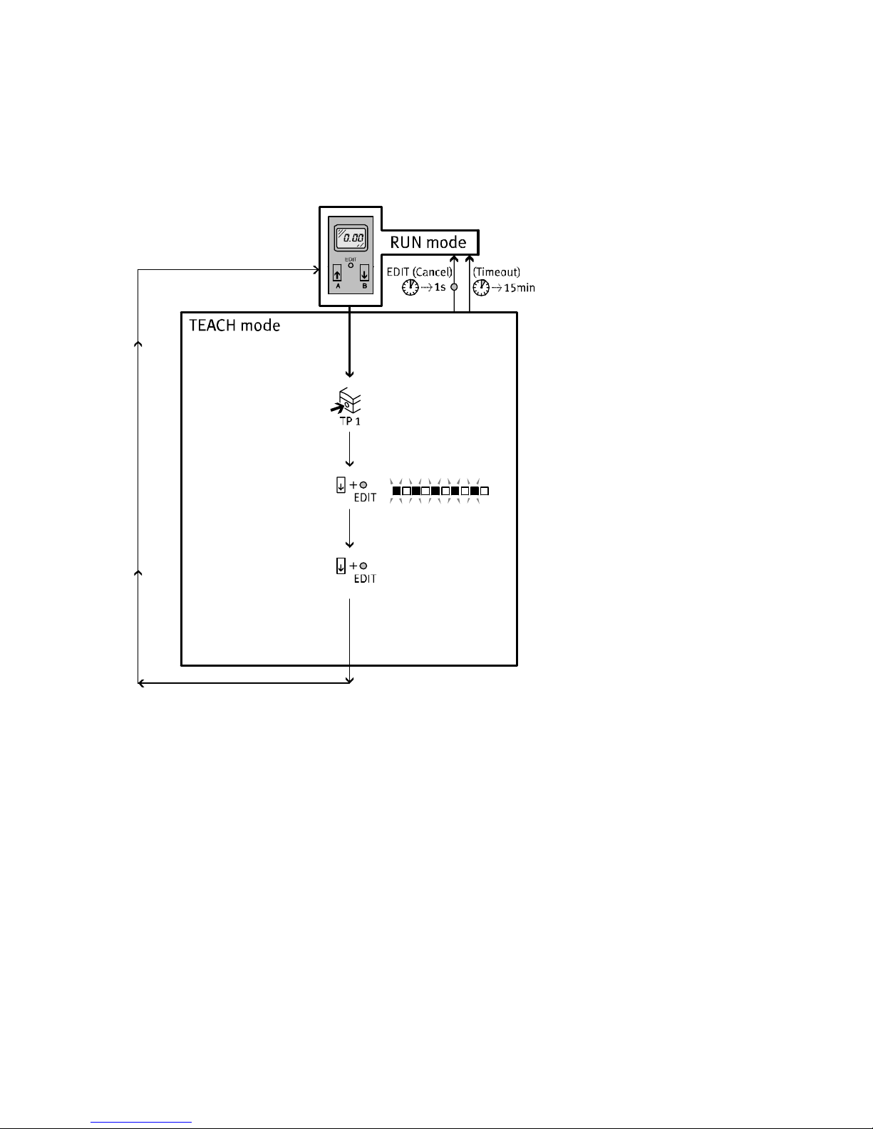
In the TEACH mode the basic pressure is ascertained from measured differential
pressure values within a time interval. The basic pressure must be ascertained
when the fine/micro filter is first commissioned.
Please note
When the filter cartridge has been replaced, the basic pressure need not be
ascertained again. The basic pressure must be ascertained again only if the
conditions of use for the fine/micro filters have been modified (e.g. if the
device is fitted into a new system or if modifications have been made
to the
compressed air system).
S Proceed as follows:
1. Commission the system.
Wait until pressure fluctuations in your system have been reduced to a
minimum.
2. In order to start the measurement, press first the DOWN button, then also the
EDIT button.
5 segments in the bar display flash. The differential pressure is measured
continuously. If
the measurement is not concluded after max. 15 minutes, the
device will return to the RUN mode without modification.
3. In order to conclude the measurement, press the DOWN button again, then
also the EDIT button.
The device is then in the RUN mode again.
The basic pressure is calculated from the differential pressure
measured and saved. The display shows 0% contamination. If there is an error,
Err" will be shown (è section 9, Eliminating faults).
44
values
Festo MSŪ−LFM−Ū−DP/DN/DPI/DNI 0611NH English
Page 45
MSŪ−LFM−Ū−DP/DN/DPI/DN I
Instructions for faultless operation
Please note the following points:
S In order to guarantee economical and reliable operation, the fine/micro filter
should be operated in the differential presssure range up to 350mbar.
S The necessity to replace the contaminated filter cartridge can be recognized in
advance by a suitable switching point setting less
S The differential pressure in the fine/micro filter depends on the flow and on
the degree of contamination. If the quality of the compressed air remains un
changed and if the flow remains constant, fixed intervals can be planned for
replacing the filter cartridges.
than 350mbar.
S The basic pressure ascertained depends on the
system and the flow. Excessive
flow or an incorrectly dimensioned system can lead to a high basic pressure.
This reduces the measuring range to the recommended switching threshold of
350mbar (maximum pressure).
S A higher set value with the time−constant measured value smoothing helps to
switching signals which have been incorrectly output due to
flow jumps
(e.g.when the system is switched on). The measured value smoothing applies
only to the switching output. The analogue output on the product designs
MSŪ−LFM−Ū−DPI/DNI outputs its signal unsmoothed.
Resetting the device to the factory setting
(also if the security code cannot be found)
Please note
The current settings will be lost after a reset to the factory setting.
S If necessary, make a note of these settings before a reset.
In order to reset the device to the factory setting:
1. switch off the operating voltage
2. press all three setting elements simultaneously (UP/DOWN button and EDIT
button) and
rES" then appears on the display.
Festo MSŪ−LFM−Ū−DP/DN/DPI/DNI 0611NH English
switch the operating voltage on again.
45
Page 46
MSŪ−LFM−Ū−DP/DN/DPI/DN I
7 Care and maintenance
Cleaning
S Switch off the following sources of energy before cleaning the exterior of the
device:
the operating voltage
the compressed air supply.
S If necessary, clean the exterior of the fine/micro filter MSŪ−LFM−Ū and the filter
contamination recognition with display MSŪ−LFM−Ū−DP/DN/DPI/DNI.
Permitted cleaning agents are soap suds (max. +50 °C) and
8 Accessories
Designation Type
Socket with cable M8x1, 3−pin
Fig.11
9Eliminating faults
Fault Possible cause Remedy
M12x1, 4−pin
non−abrasive media.
SIM−M8−3Ū
SIM−M12−4Ū
No display No power supply or no
46
permitted operating voltage
Connections swapped
(incorrect polarity)
MSŪ−LFM−Ū−DP/DN/DPI/DNI
defective
Festo MSŪ−LFM−Ū−DP/DN/DPI/DNI 0611NH English
Switch on power supply /
maintain permitted operating
voltage range
Wire the
MSŪ−LFM−Ū−DP/DN/DPI/DNI
in accordance with the circuit
diagram.
Send the complete fine/
micro filter to Festo.
Page 47
MSŪ−LFM−Ū−DP/DN/DPI/DN I
p)
Fault RemedyPossible cause
Incomplete display Display defective Send the complete fine/
micro filter to Festo.
Pressure indicator
flashes
Err" will be shown on
the display
(ascertained basic
pressure greater than
maximum basic
pressure).
Outputs do not switch
according to settings
Settings cannot be
edited (lock" on the
display)
Dirty filter element Replace filter cartridge
Non−permitted flow range Note permitted flow range of
the fine/micro filter.
Flow jumps" (not constant) Increase the time−constant
measured value smoothing
Flow too high (e.g. when the
system is switched on)
Note permitted flow range of
the fine/micro filter and
ascertain again the basic
pressure.
Dirty filter element Replace filter cartridge
Fine/micro filter not of
Replace fine / micro filter
correct size
Short circuit/overload at
relevant output
MSŪ−LFM−Ū−DP/DN/DPI/DNI
defective
Eliminate short circuit/
overload
Send the complete fine/
micro filter to Festo.
Access protection active Enter the security code
(if forgotten, reset as
described in Operation")
Fig.12
Festo MSŪ−LFM−Ū−DP/DN/DPI/DNI 0611NH English
47
Page 48
MSŪ−LFM−Ū−DP/DN/DPI/DN I
10 Technical specifications
MSŪ−LFM−Ū −DP −DN −DPI −DNI
Pressure measuring range
[bar] 0 Ū 1
1)
(differential pressure)
Input pressure at fine/
[bar] Ţ 10
micro filter MSŪ−LFM
Assembly position vertical
Setting range
switching pressure
hysteresis
switching pressure
hysteresis
Ambient temperature
Medium temperature
Storage temperature
[%]
[%]
[bar]
[bar]
[°C]
[°C]
[°C]
0 Ū 100
0 Ū 100
0.020 Ū 0.998
0 Ū 0.9
1)
0 Ū +50
0 Ū +50
0 Ū +50
1)
Operating voltage range [VDC] 15Ū30 (permitted residual ripple max. 10%)
Idle current [mA] max. 45 (approx. 40 typ.)
Ready−state delay [ms] max. 450 (with suppression of incorrect
switch−on pulse)
Max. permitted signal
line length
1)
Values for the units kPa" and psi" must be converted with the appropriate factors.
Fig.13
48
[m] 30
Festo MSŪ−LFM−Ū−DP/DN/DPI/DNI 0611NH English
Page 49
MSŪ−LFM−Ū−DP/DN/DPI/DN I
MSŪ−LFM−Ū −DP −DN −DPI −DNI
Switching outputs positive
switching
(PNP)
Perm. switching current
Switchable capacity
Induction protection
Switching times (on/off)
Ana. output (current)
Permitted load
[mA]
[nF]
[ms]
[mA]
[]
max. 150
max. 100
adapted to MZ, MY, ME coils
max. 10 (5 typ.)
4 Ū 20
negative
switching
(NPN)
resistance
Protection against short circuit
Protection against polarity
pulsed
for all electrical connections
reversal
Protection class IP65 (as per EN 60529)
Protection type III (as per DIN VDE 0106−1)
Interference immunity
Interference emission
see conformity declaration (www.festo.com)
see conformity declaration (www.festo.com)
Material
Housing
MS adapter
Pushbuttons
Display
Seals
Plug
Polyamide; polyacetate (reinforced)
Polyamide (reinforced)
Nitrile rubber
Polycarbonate
Nitrile rubber
Brass
positive
switching
(PNP)
max. 300
negative
switching
(NPN)
Fig.14
Festo MSŪ−LFM−Ū−DP/DN/DPI/DNI 0611NH English
49
Page 50
MSŪ−LFM−Ū−DP/DN/DPI/DN I
11 Menu structure
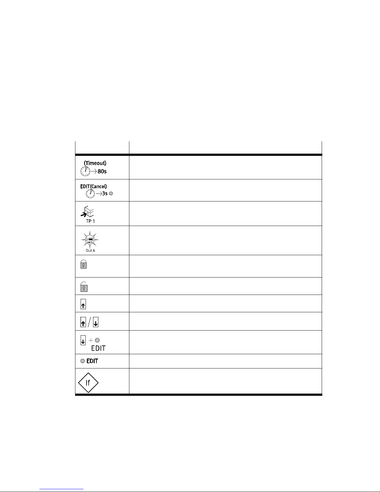
Icons for representing the menu structure
Icon
Meaning
Automatic return to the basic status (RUN mode) when the
monitoring time has expired (here 80 seconds)
In order to return manually to the basic status (RUN mode), press
the EDIT button for 3seconds
Create pressure (for teaching the basic pressure)
Icon on the display flashes (here Out A)
Security code active
(Lock locked against unauthorized programming)
Security code inactive
Press button (here UP button)
Press UP or DOWN button
Fig.15
50
Press the DOWN button and the EDIT button simultaneously
Press the EDIT button briefly
Branching in the menu system
Festo MSŪ−LFM−Ū−DP/DN/DPI/DNI 0611NH English
Page 51
MSŪ−LFM−Ū−DP/DN/DPI/DN I
Fig.16: EDIT mode
Festo MSŪ−LFM−Ū−DP/DN/DPI/DNI 0611NH English
51
Page 52
MSŪ−LFM−Ū−DP/DN/DPI/DN I
Fig.17: SHOW mode
52
Festo MSŪ−LFM−Ū−DP/DN/DPI/DNI 0611NH English
Page 53
MSŪ−LFM−Ū−DP/DN/DPI/DN I
Fig.18: TEACH mode (only possible with set unit %")
Festo MSŪ−LFM−Ū−DP/DN/DPI/DNI 0611NH English
53
Page 54

MSŪ−LFM−Ū−DP/DN/DPI/DN I
54
Festo MSŪ−LFM−Ū−DP/DN/DPI/DNI 0611NH English
Page 55

MSŪ−LFM−Ū−DP/DN/DPI/DN I
Festo MSŪ−LFM−Ū−DP/DN/DPI/DNI 0611NH
55
Page 56

MSŪ−LFM−Ū−DP/DN/DPI/DN I
+49/711/347−2144
Weitergabe sowie Vervielfältigung dieses Dokuments,
Verwertung und Mitteilung seines Inhalts sind verboten,
soweit nicht ausdrücklich gestattet. Zuwiderhandlungen
verpflichten zu Schadenersatz. Alle Rechte sind für den
Fall der Patent−, Gebrauchsmuster oder Geschmacks−
mustereintragung vorbehalten.
The reproduction, distribution and utilization of this docu
ment as well as the comunication of its contents to others
without express authorization is prohibited. Offenders will
be held liable for the payment of damages. All rights re
served in the event of the grant of a patent, utility module
or design.
56
Copyright:
EFesto AG&Co. KG,
Postfach
D−73726 Esslingen
Phone:
+49/711/ 347−0
Fax:
+49/711/347−2144
e−mail:
service_intern ati onal@ fes to. com
Internet:
http://www.festo.com
Original: de
Version: 0611NH
Festo MSŪ−LFM−Ū−DP/DN/DPI/DNI 0611NH
 Loading...