

Page 1
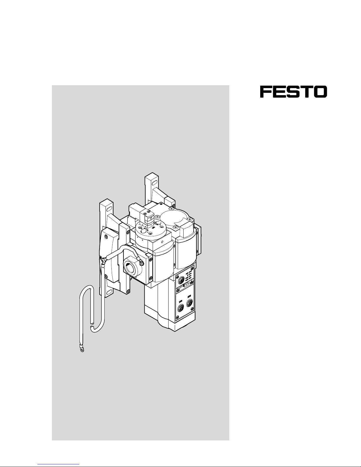
Description
Mounting
Installation
Commissioning
8074159
2017-07c
[8074161]
MSE6-E2M
Energy efficiency module
Page 2
MSE6-E2M
2 Festo – MSE6-E2M-IN-EN – 2017-07c – English
MSE6-E2M-IN-EN
PI PROFIBUS PROFINET
®
, PROFIenergy® are registered trademarks of the respective trademark
owners in certain countries.
Identification of hazards and instructions on how to prevent them:
Warning
Hazards that can cause death or serious injuries
Caution
Hazards that can cause minor injuries
Other symbols:
Note
Material damage or loss of function
Recommendations, tips, references to other documentation
Essential or useful accessories
Information on environmentally sound usage
Text designations:
Activities that may be carried out in any order
1. Activities that should be carried out in the order stated
– General lists
Page 3

MSE6-E2M
Festo – MSE6-E2M-IN-EN – 2017-07c – English 3
Table of Contents – MSE6-E2M
1 Safety and requirements for product use 6......................................
1.1 Safety 6..................................................................
1.1.1 General safety information 6..........................................
1.1.2 Intended use 6.....................................................
1.1.3 Foreseeable misuse 7...............................................
1.2 Requirements for product use 7...............................................
1.2.1 Technical prerequisites 7............................................
1.2.2 Qualification of specialized personnel 7.................................
1.2.3 Range of application and certifications 8................................
2 Overview 9................................................................
2.1 Design 9..................................................................
2.1.1 Overview of product features 9.......................................
2.1.2 Mode of operation 11................................................
2.2 Commissioning, diagnostics and operational functions 12............................
3 Mounting and installation 14..................................................
3.1 General instructions 14.......................................................
3.2 Mounting 15................................................................
3.3 Combination with MS6 modules 17..............................................
3.4 Dismounting 19.............................................................
3.5 Installation 20..............................................................
3.5.1 General instructions for installation 20...................................
3.5.2 Bus node settings 20.................................................
3.5.3 Selecting the power supply unit 21......................................
3.5.4 Power supply of the MSE6-E2M 22......................................
4 Commissioning 25...........................................................
4.1 Approach 26................................................................
4.2 Prior to commissioning 27.....................................................
4.3 Brief instructions for commissioning 28..........................................
4.4 Options for parameterisation 29................................................
4.5 Start-up behaviour 29........................................................
5 Measurement and control functions 30..........................................
Page 4

MSE6-E2M
4 Festo – MSE6-E2M-IN-EN – 2017-07c – English
6 Input/output data 31.........................................................
6.1 Overview 31................................................................
6.2 Description of the I/O data 31..................................................
6.3 Function selectable input data 31...............................................
7 Parameterisation 32.........................................................
8 Diagnostics and error handling 33..............................................
8.1 Summary of diagnostics options 33.............................................
8.2 On the spot diagnostics via LED 34..............................................
8.3 Diagnosis via status bits or the I/O diagnostic interface 34...........................
8.4 Error numbers 35............................................................
A Technical appendix 37........................................................
A.1 Technical data 37............................................................
A.2 Connecting cable 40..........................................................
B Glossary 42................................................................
Index 43........................................................................
Page 5

MSE6-E2M
Festo – MSE6-E2M-IN-EN – 2017-07c – English 5
Notes on this description
This description contains general basic information on the mode of operation, mounting, installation
and commissioning of the energy efficiency module MSE6-E2M.
Further information on commissioning and parameterisation can be found in the system description for
the energy efficiency module (è MSE6-E2M-SY-…).
Special information on commissioning, parameterisation and diagnostics with the bus node you are
using can be found in the corresponding description for the bus node.
Overview of the descriptions è Tab. 1.
Conventions
Chapter 7 describes the parameters and data of the MSE6-E2M. These appear on the operator unit
CPX-MMI-1 in English.
[........] The data and parameters in the text displayed in English on the operator unit are shown in
square brackets in this description, e.g. [Limits]. To the left of this is the translation, e.g.:
Limit values [Limits]
Service
Consult your local Festo repair service if you have technical problems.
Additional documentation è www.festo.com/sp
User documentation for the MSE6-E2M
Title Table of contents
“Energy efficiency module”
MSE6-E2M-SY-...
Instructions on commissioning and parameterisation for the
energy efficiency module.
“CPX terminal”
P.BE-CPX-SYS-...
Notes and installation and commissioning of CPX terminals.
“Bus node”
e.g. P.BE-K-CPX-PNIO-...
Brief descriptions of the bus nodes, e.g. CPX(M)-FB33/34/35.
“Bus node”
e.g. P.BE-CPX-PNIO-...
Notes on mounting, installation, commissioning and diagnostics
for the bus nodes, e.g. CPX(M)-FB33/34/35.
“Operator unit”
P.BE-CPX-MMI-1-...
Notes on commissioning and diagnostics with the operator unit
CPX-MMI-1.
Tab. 1 Descriptions for the MSE6-E2M
Page 6
1 Safety and requirements for product use
6 Festo – MSE6-E2M-IN-EN – 2017-07c – English
1 Safety and requirements for product use
1.1 Safety
1.1.1 General safety information
Warning
Risk of injury
If there is an error (e.g. fieldbus interruption, PLC failure, no voltage) on the MSE6-E2M,
then the shut-off valve switches to the initial position (pressurise) if the system para
meters are set accordingly. If the valve was previously closed, the system is pressurized.
If the system was vented, pressurisation takes place suddenly.
Use appropriate measures to ensure that unintentional pressurisation of the system
is not possible.
Warning
Risk of injury due to residual pressure
When the input pressure is being switched off (e.g. during a venting procedure), a resid
ual pressure of P2 1 bar (P2 0,1 MPa) can remain at the output of the MSE6-E2M.
Use appropriate measures to ensure that the residual pressure does not result in a
hazard.
Note
Damage to the product from incorrect handling
Switch off the compressed air and supply voltage before performing assembly and
installation work. Switch on supply voltage only when assembly and installation
work are completely finished.
Observe the handling specifications for electrostatically sensitive devices.
1.1.2 Intended use
The energy efficiency module MSE6-E2M is intended for installation in a machine or automated system
and must be used exclusively as follows:
– In perfect technical condition
– In original status, without unauthorised modifications
– Within the limits of the product defined by the technical data (è Appendix A)
– In an industrial environment (outside of industrial environments, e.g. in commercial and mixed-res
idential areas, actions to suppress interference may have to be taken)
Page 7

1 Safety and requirements for product use
Festo – MSE6-E2M-IN-EN – 2017-07c – English 7
1.1.3 Foreseeable misuse
Note
In the event of damage caused by unauthorised manipulation or other than intended
use, the guarantee is invalidated and the manufacturer is not liable for damages.
The following foreseeable misuses are among those not approved as intended use:
– Use outdoors
– Shutting off of a system as a safety function
– Use in safety functions:
– The MSE6-E2M must not be installed behind an exhaust valve that fulfils a safety function, since
otherwise the safety functions installed in the system can be impeded.
– For installation of the MSE6-E2M in front of a safety valve, it must be ensured, possibly through
additional suitable measures, that this layout does not impair the intended operation of the
safety valve and of the system.
1.2 Requirements for product use
Make this documentation available to the design engineer, installer and personnel responsible for
commissioning the machine or system in which this product is used.
Make sure that the specifications of the documentation are always complied with. Also consider the
documentation for the other components and modules (e. g. bus node).
Take into consideration the legal regulations applicable for the destination, as well as:
– Regulations and standards,
– Regulations of the testing organizations and insurers,
– National specifications.
1.2.1 Technical prerequisites
General conditions for the correct and safe use of the product, which must be observed at all times:
Comply with the connection and ambient conditions specified in the technical data of the product
(è Appendix A.1).
Observe the instructions and warnings in this documentation.
1.2.2 Qualification of specialized personnel
The product may only be placed in operation by qualified personnel with knowledge of and experience
with electrical and pneumatic control technology.
Page 8

1 Safety and requirements for product use
8 Festo – MSE6-E2M-IN-EN – 2017-07c – English
1.2.3 Range of application and certifications
Standards and test values, which the product complies with and fulfils, can be found in the “Technical
data” section (è Appendix A.1). The product-relevant EU directives can be found in the declaration of
conformity.
For certificates and the declaration of conformity for this product, please refer to
è www.festo.com/sp.
The product fulfils the requirements of EU directives and is marked with the CE marking.
Page 9

2 Overview
Festo – MSE6-E2M-IN-EN – 2017-07c – English 9
2Overview
2.1 Design
The MSE6-E2M is an intelligent pneumatic service unit, which is equipped with measurement, control
and diagnostic functions and which supports energy-efficient operation of pneumatic systems. The
module is typically assembled behind a service unit combination.
The MSE6-E2M consists of the main components: shut-off valve, flow sensor, pressure sensor and bus
node. The fieldbus interface allows complete integration into a higher-order controller, e.g. a system or
machine controller. As an alternative to integration into a higher-order controller, the MSE6-E2M can
also be operated using an external operator unit (CPX-MMI) or a PC.
2.1.1 Overview of product features
– Control function (energy efficiency function)
– Automatic shut-off on flow underrunning
– User-controlled shut-off and pressurising
– Recording and provision of measurement data
– Output pressure
– Pressure change (for pressure tightness testing)
–Flow
– Air consumption
– Limit monitoring
– Pressure, upper limit value
– Pressure change, upper limit value
– Flow, upper limit value
– Fieldbus connection
– e.g. PROFINET IO (e.g. CPX-FB33)
– e.g. PROFIBUS (CPX-FB13)
Page 10
2 Overview
10 Festo – MSE6-E2M-IN-EN – 2017-07c – English
4
5
3
1
6
7
2
2
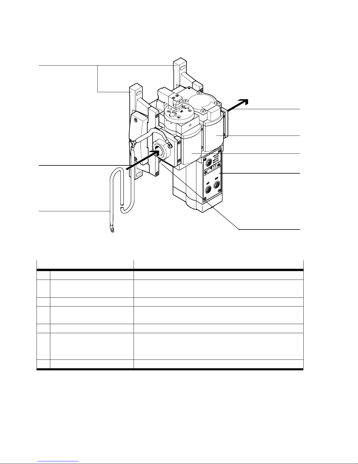
Fig. 2.1 Design (at the bus node as an example CPX-FB33)
MSE6-E2M Brief description
1 Earth terminal FE connection of the device
2 Pneumatic ports – Pneumatic connection 1: compressed air inlet
– Pneumatic connection 2: compressed air outlet
3 Wall bracket Mounting of the device
4 Sensor module Module for measuring pressure, flow and consumption as well
as activation of the shut-off valve
5 Shut-off valve Used to enable and shut-off the system supply air.
6 Bus node Creates the communicative connection to a higher-order con
troller through a fieldbus, passes on the control signals to the
integrated sensor module and monitors their functioning.
7 System supply Electrical power supply of the device
Tab. 2.1 Individual functions
Page 11
2 Overview
Festo – MSE6-E2M-IN-EN – 2017-07c – English 11
2.1.2 Mode of operation
Machine/sys
tem
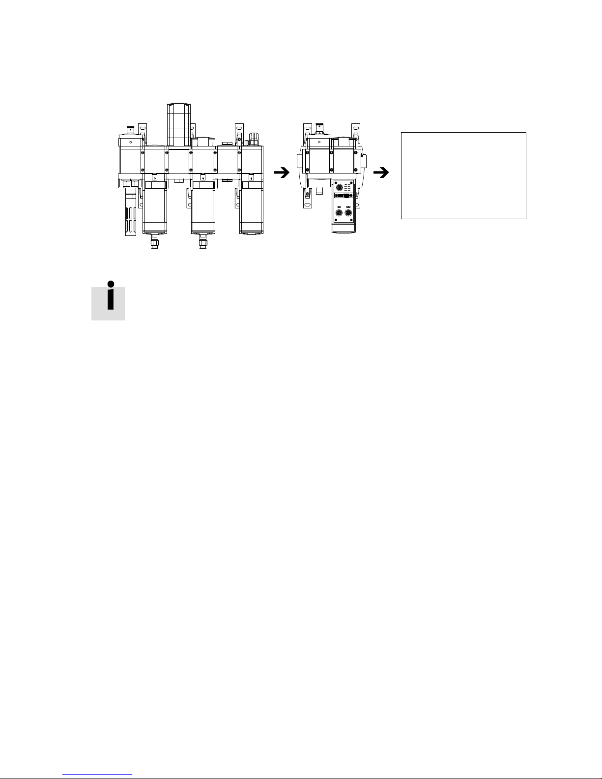
Fig. 2.2 Typical installation position (as an example at the bus node CPX-FB33)
The MSE6-E2M is typically assembled behind a service unit combination.
It allows venting of the following system, both in the “Pressurise” state and in the “Shutoff ” state through a reverse flow (2 à 1). In the shut-off state, the reverse flow is consid
erably reduced. For this reason, for more rapid venting, the MSE6-E2M should be in the
“Pressurise” status.
The key functions are:
Standby detection and automatic shut-off of the compressed air supply
The MSE6-E2M uses settable parameters to detect production down times of a pneumatic system. The
system is separated from the compressed air supply using the 2/2 shut-off valve, without venting the
subsequent system. This avoids additional air consumption through leakages. If production is to con
tinue on the system, then it must be signaled to the MSE6-E2M. The shut-off valve opens and the sys
tem is again supplied with compressed air.
Automatic shut-off of the compressed air supply can be activated and deactivated by the user. In the
deactivated status, the shut-off valve can be controlled directly by the PLC.
Pressure tightness testing
When in the shut-off state, the MSE6-E2M measures the pressure curve over time.
Even in well-serviced systems, the pressure falls continuously due to leakages. The fewer leakages the
system has, the slower the pressure drop will be. The measured pressure change serves as a measure
of the leakage existing in the system. If the parameterised limit value is exceeded, then the device will
output a diagnostic message.
Pressure recording
The MSE6-E2M continuously measures the output pressure, prepares the data and makes it available
cyclically.
To detect high operating pressures, the MSE6-E2M offers the option of parameterising limit values for
pressure. If the parameterised limit value is exceeded, then the device will output a diagnostic mes
sage.
Page 12
2 Overview
12 Festo – MSE6-E2M-IN-EN – 2017-07c – English
Flow recording
The MSE6-E2M continuously records the flow, prepares the data and makes it available cyclically.
To detect high flow rates, the MSE6-E2M offers the option of parameterising limit values for the flow. If
the parameterised limit value is exceeded, then the device will output a diagnostic message.
Consumption recording
The MSE6-E2M determines the compressed air consumption by recording the system flow rate. The
user has the option of using appropriate signaling to record the compressed air consumption over a
specific period of time.
2.2 Commissioning, diagnostics and operational functions
The system reaction of the MSE6-E2M can be adapted to the relevant application. The MSE6-E2M
provides extensive functions for commissioning, diagnosis and operation.
Commissioning and operational functions
The MSE6-E2M is supplied from the factory with preset parameters.
The behaviour of the MSE6-E2M can be adapted to the respective requirements through parameterisa
tion. The following behaviour can be influenced, for example, by accessing the internal parameters:
– The diagnostic behaviour by enabling maskable diagnostic messages
– Specification of the units and the measuring interval
– Setting of limit values
– The operating method of the diagnostic memory.
Caution
A different parameterisation will result in different characteristics.
In particular, check which settings are required when replacing the MSE6-E2M.
Ensure that the settings can be restored (e.g. in the start-up phase by the higher-or
der PLC/IPC).
Basic information on the different parameters can be found in Chapter 7. A detailed de
scription of the parameters can be found in Chapter 7 of the system description for the
energy efficiency module (è MSE6-E2M-SY-…).
Page 13

2 Overview
Festo – MSE6-E2M-IN-EN – 2017-07c – English 13
Diagnostic functions
Extensive diagnostic information can be accessed, depending on the fieldbus used.
Diagnostic information
Brief description
Status bits Common diagnostic messages (global error messages) are displayed by
means of 8 internal inputs (8 status bits).
I/O diagnostic
interface
With fieldbuses that do not possess extensive diagnostic functions, the
diagnostic information of the MSE6-E2M is available via the I/O diagnostic
interface. The I/O diagnostic interface enables bus-independent access to
diagnostic information, data and parameters via internal digital I/Os
(16 inputs and 16 outputs).
Diagnostic memory Errors which occur during operation are entered in a diagnostic memory.
The first or the last 40 entries are saved, as well as the respective time
measured from the moment the power supply was switched on.
Fieldbus-specific dia
gnostic functions
Special diagnostic functions or communication services are available,
depending on the fieldbus used.
Tab. 2.2 Diagnostic information
Page 14
3 Mounting and installation
14 Festo – MSE6-E2M-IN-EN – 2017-07c – English
3 Mounting and installation
3.1 General instructions
Warning
Uncontrolled movements of the connected actuator technology and loose tubing can
cause injury to persons and/or damage to property.
Before carrying out mounting, installation and maintenance work, switch off the follow
ing:
Compressed air supply including venting of the system
Operating and load voltage supplies.
Note
Electrostatically sensitive devices
Do not touch any components.
Observe the handling specifications for electrostatically sensitive devices.
Note
For the combination of the MSE6-E2M with MS6 modules, please observe the corres
ponding mounting instructions (è Chapter 3.3).
Pay particular attention to the following:
Screw connections must be made without warping and mechanical stress. Position
screws exactly before tightening (otherwise their threads will be damaged).
Observe the specified tightening torques.
Contact surfaces must be clean (avoid leakage and contact errors).
Seal the unused connections with protective caps or blanking plugs, in order to
achieve the required degree of protection.
Page 15
3 Mounting and installation
Festo – MSE6-E2M-IN-EN – 2017-07c – English 15
3.2 Mounting
Note
Mount the MSE6-E2M so that there is sufficient space for heat dissipation and ensure
that the maximum limit values for temperatures are observed (è Technical data).
Note
Place the MSE6-E2M in such a position in your system that the necessary air quality
class for the operating medium is maintained (è Technical Data).
Note
Fasten the MSE6-E2M with screws of size M6 and use washers, if required.
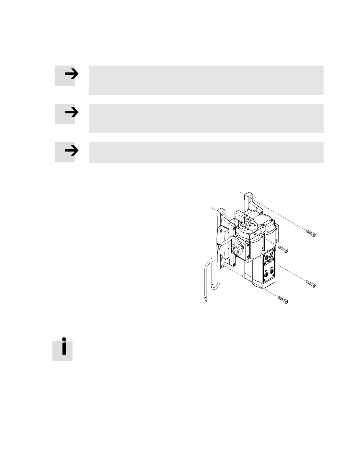
The MSE6-E2M is intended for mounting on the wall. The mounting brackets are integrated and contain
drill holes for wall mounting.
1. Ensure that the compressed air supply, as well as
the operation and load/actuator supply, are
switched off.
2. Make sure that the fastening surface is flat and can
support the weight of the MSE6-E2M.
3. Adjust the MSE6-E2M when it is standing vertically
(±5°).
4. Fasten the MSE6-E2M using the mounting brackets
and 2 screws each (è Fig. 3.1).
Fig. 3.1 Typical mounting (as an example
at the bus node CPX-FB33)
Make sure there is sufficient space for connecting the power supply cables and tubing.
After mounting, connect all electrical and pneumatic connections of the MSE6-E2M in this order:
1. Connect the pneumatic connections.
2. Connect the earth terminal.
3. Connect the electrical connecting cable to the power supply.
4. Connect the fieldbus cable to the bus node.
Page 16
3 Mounting and installation
16 Festo – MSE6-E2M-IN-EN – 2017-07c – English
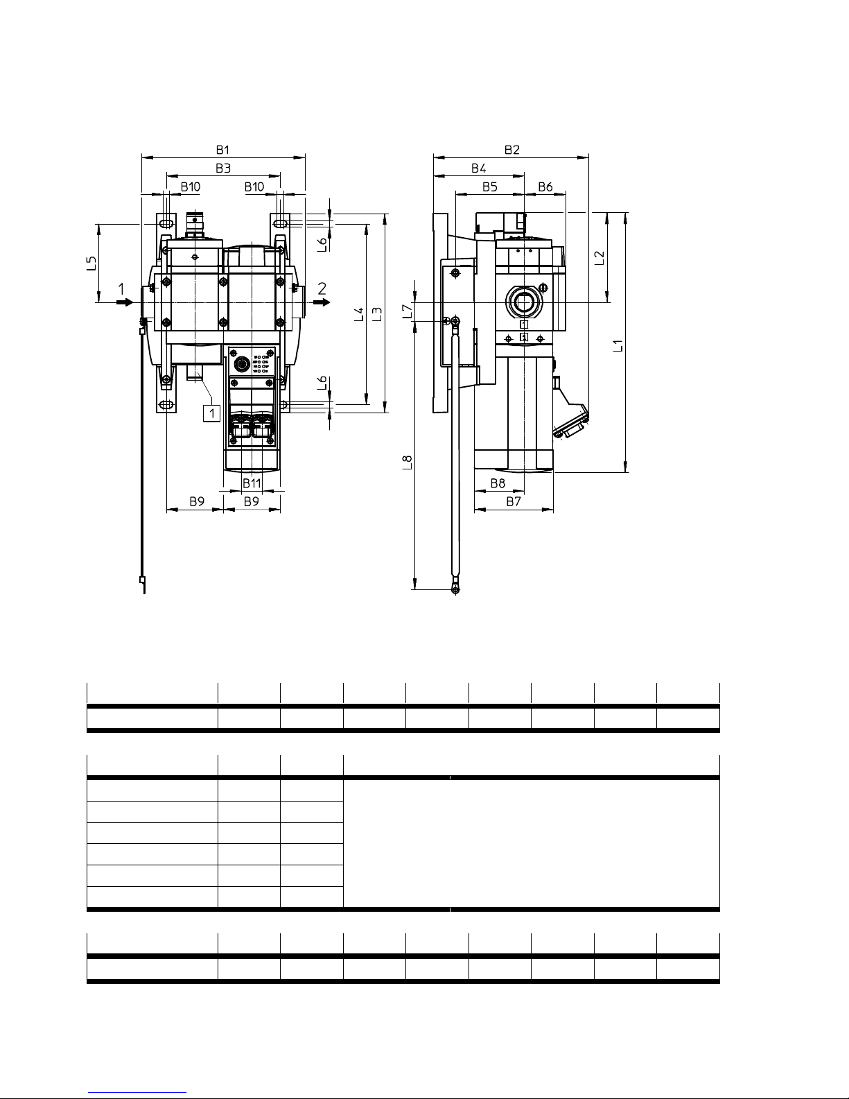
Dimension MSE6-E2M
1 Connecting thread M18x1, 4-pin
Fig. 3.2 Dimension (as an example at the bus node CPX-FB34/35)
Type B1 B3 B4 B5 B6 B8 B9 B10
MSE6-E2M 178 124 99 75 45 55 62 7
Type B2 B7 Connection technology
CPX-FB13 150 100 Depending on the bus node, additional space for the con
nection technology is required for mounting.
CPX-FB33 145 86
CPX-FB34 170 86
CPX-FB35 170 86
CPX-FB36 145 86
CPX-FB37 145 86
Type L1 L2 L3 L4 L5 L6 L7 L8
MSE6-E2M 285 98 217 197 86 7 21 292
Fig. 3.3 Dimension table [mm]
Page 17

3 Mounting and installation
Festo – MSE6-E2M-IN-EN – 2017-07c – English 17
3.3 Combination with MS6 modules
Note
Observe the notes regarding installation and commissioning of MS6 modules in the
corresponding documentation.
Note
Observe the maximum permissible number of ten individual modules for the overall
combination. The MSE6-E2M counts as a double module here.
Note
When supplementing MS6 modules, only use the MS6-WPG wall mounting and the
MS6-MV-EX module connector.
Note
Observe the notes regarding the procedure for left and/or right-hand side assembly of
maintenance modules, as described in the assembly instructions for the MS6-WPG wall
mounting set.
Note
Please note that when using a MS6-SV-D, a MS6-WPG wall mounting set may not be
mounted on the right-hand side due to a mechanical conflict with the sensor cables.
Alternatively, an MS6-FRM-FRZ distributor block can be inserted.
Note
Please note that in the case of a larger device configuration, a longer FE connection is
required.
For the left and/or right-hand side supplement of the MSE6-E2M with MS6 modules, proceed as follows:
1. Use an MS6-WPG wall mounting set for MS6 individual modules or, in the case of pre-assembled
MS6 combinations, replace the MS6 wall brackets with the wall mounting set.
2. For MS6 individual modules use MS6-MV-EX module connectors or, in the case of pre-assembled
MS6 combinations, replace all of the standard module connectors with these module connectors.
For a left-hand supplement, proceed as follows:
3. Remove the left-hand pneumatic base plate of the MS6 module or MS6 module combination re
spectively and assemble the left-hand pneumatic base plate of the MSE6-E2M at this point.
4. Connect the earth terminal on the left-hand pneumatic base plate with low impedance (short cable
with large cross section) to the left end plate of the electrical interlinking module of the MSE6-E2M.
Page 18
3 Mounting and installation
18 Festo – MSE6-E2M-IN-EN – 2017-07c – English
For a right-hand supplement, proceed as follows:
5. Remove the right-hand pneumatic base plate of the MS6 module or MS6 module combination re
spectively and assemble the right-hand pneumatic base plate of the MSE6-E2M at this point.
When mounted correctly, a low-impedance connection must exist between the earth terminals of the
left and right-hand pneumatic base plate.
With low-impedance connections, make sure that the earth terminal at the left end plate of the
electrical interlinking module on the MSE6-E2M and the earth terminal at the power supply connec
tion have the same potential and that there are no compensating currents. If necessary, the preassembled electrical connection of the MSE6-E2M must be replaced by a longer, electrically equival
ent connection.
By following this approach you will prevent interference from electromagnetic sources and ensure
electromagnetic compatibility in accordance with EMC directives.
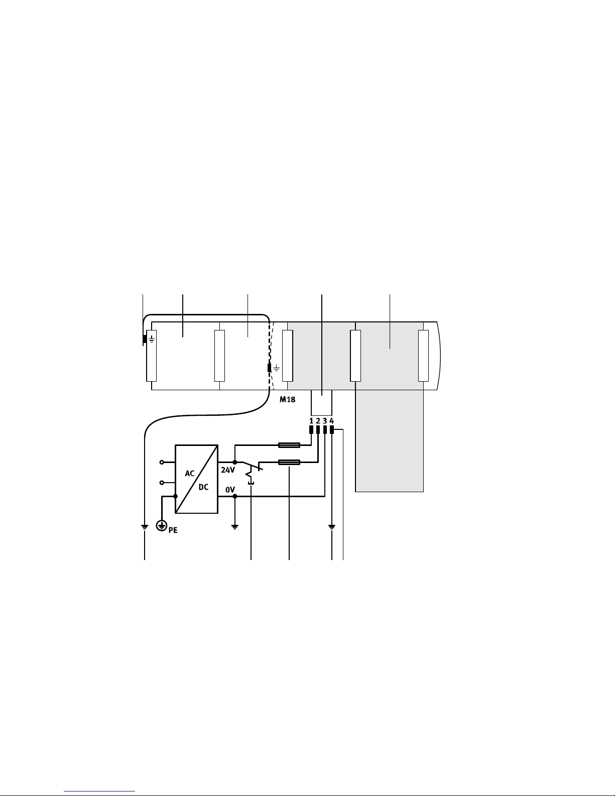
12 34
5678
2
6
1 Potential equalisation between the earth ter
minal of the left-hand pneumatic base plate
and the left end plate of the electrical inter
linking module
2 MS6 module
3 System supply
4 MSE6-E2M (marked with a grey background)
5 Earth terminal on pin 4, rated for max. 16 A
6 Potential equalisation of functional earth (FE)
7 External fuses
8 Separately switchable actuator technology
supply
Fig. 3.4 Power supply of the MSE6-E2M with MS6 modules
Page 19
3 Mounting and installation
Festo – MSE6-E2M-IN-EN – 2017-07c – English 19
3.4 Dismounting
Warning
Switch off the following before dismounting the MSE6-E2M:
Compressed air supply including venting of the system
Operating and load voltage supplies.
Warning
Risk of injury due to residual pressure
When the input pressure is being switched off (e.g. during a venting procedure), a resid
ual pressure of P2 1 bar (P2 0,1 MPa) can remain at the output of the MSE6-E2M.
Use appropriate measures to ensure that the residual pressure does not result in a
hazard.
Warning
Loads which suddenly fall down may cause injury to people.
Take the product's weight into account. The MSE6-E2M has a product weight of
max. 3.5 kg.
Dismount the MSE6-E2M in this sequence:
1. Remove the fieldbus cable from the bus node.
2. Remove the electrical connection cable.
3. Remove the earth connection.
4. Loosen the pneumatic connections.
5. Loosen the screws from all mounting brackets, one after the other. Start with the screws beneath
the MSE6-E2M.
6. Remove the complete MSE6-E2M.
Page 20
3 Mounting and installation
20 Festo – MSE6-E2M-IN-EN – 2017-07c – English
3.5 Installation
3.5.1 General instructions for installation
Warning
Uncontrolled movements of the connected actuator technology and loose tubing can
cause injury to persons and/or damage to property.
Before carrying out installation and maintenance work, switch off the following:
– Compressed air supply including venting of the system
– Operating and load voltage supplies.
Warning
Risk of injury due to residual pressure
When the input pressure is being switched off (e.g. during a venting procedure), a resid
ual pressure of P2 1 bar (P2 0,1 MPa) can remain at the output of the MSE6-E2M.
Use appropriate measures to ensure that the residual pressure does not result in a
hazard.
3.5.2 Bus node settings
Each bus node has a service interface. Additional electric interfaces, setting and display components
are available, depending on the bus node used. A detailed description of the equipment characteristics
can be found in the corresponding brief description of the bus node (è Tab. 1) or in the system descrip
tion for the energy efficiency module (è MSE6-E2M-SY-…).
Page 21
3 Mounting and installation
Festo – MSE6-E2M-IN-EN – 2017-07c – English 21
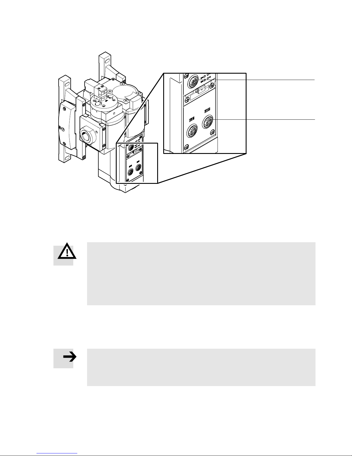
2
1
1 Service interface 2 Fieldbus connection
Fig. 3.5 Bus node (as an example at the bus node CPX-FB33)
3.5.3 Selecting the power supply unit
Warning
For the electrical power supply, use only PELV circuits in accordance with
IEC 60204-1/EN 60204-1 (Protective Extra-Low Voltage, PELV).
Also take into account the general requirements for PELV circuits in accordance with
IEC 60204-1/EN 60204-1.
Use only voltage sources that ensure a reliable electric separation of operating
voltage from the network in accordance with IEC 60204-1/EN 60204-1.
Through the use of PELV circuits, protection from electric shock (protection from direct and indirect
contact) is ensured in accordance with IEC 60204-1/EN 60204-1 (refer to Electrical Equipment of Ma
chines. General Requirements).
Note
Use regulated power supplies to ensure that the load voltage of the outputs always
remains within the permitted tolerances during operation (è Chapter 3.5.4).
Make sure that the selected power supply units provide sufficient power.
Page 22
3 Mounting and installation
22 Festo – MSE6-E2M-IN-EN – 2017-07c – English
3.5.4 Power supply of the MSE6-E2M
Operating voltage
Power supply for electronics and sensor.
Load voltage
Power supply for actuators.
Warning
Risk of injury
If the load or operating voltage of the MSE6-E2M is switched off, then the shut-off valve
switches to the initial position (pressurise). If the valve was previously closed, the sys
tem is pressurized. If the system was vented, pressurisation takes place suddenly.
Use appropriate measures to ensure that unintentional pressurisation of the system
is not possible.
Note
Check as part of your emergency off concept (action in emergency to switch off electric
energy to all or part of an installation) what measures are required to put your system in
a safe status (e.g. switching off the load voltage for the valves, switching off the com
pressed air, etc.) in case of emergency off (if there is a risk of electric shock or other risk
of electric origin).
If there is an undervoltage, the MSE6-E2M switches to the “Pressurise” status.
Note
Note that the partially tighter tolerance range must be observed when the operating
and load voltage supplies are provided by a shared power supply unit.
Tolerance ranges:
– Operating voltage: ± 25 %
– Load voltage: – 25 %,
+ 10 %
Page 23
3 Mounting and installation
Festo – MSE6-E2M-IN-EN – 2017-07c – English 23
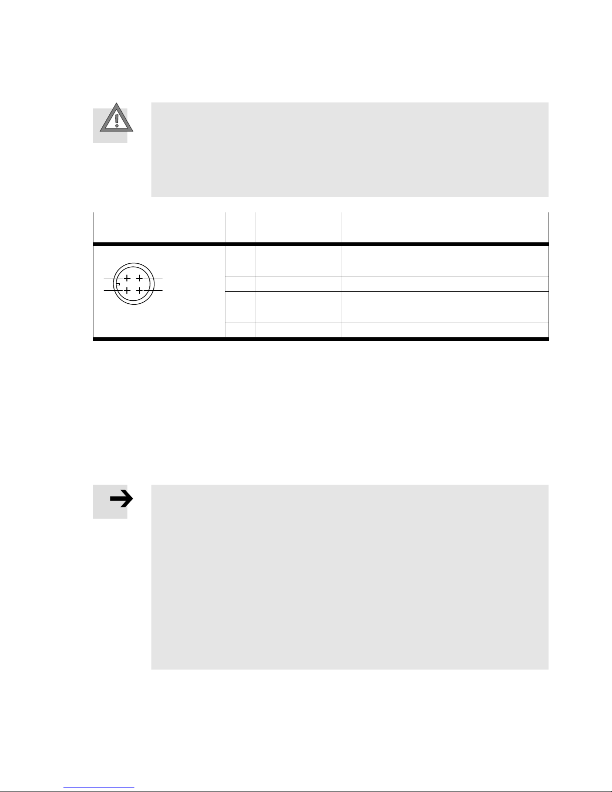
Pin allocation
Caution
Short circuits can cause damage.
Secure the system supplies externally.
The permissible current per pin at the supplies is max. 16 A.
Note that the sum of both currents of the operating and load voltages flows over
Pin 3.
Plug connector
(Top view of device)
Pin System supply Function
M18
1
2
3
4
1 24 V DC U
EL/SEN
Operating voltage supply for the electronics
and sensors
2 24 V DC U
OUT/A
Load voltage supply for actuators
3 0 V U
EL/SEN
/
0 V U
OUT/A
Operating load voltage
4 FE Functional earth
Tab. 3.1 Pin allocation, system supply
Potential equalisation
The MSE6-E2M has two earth terminals for potential equalisation:
– Pin 4 (M18 plug connector) of the power supply connection of the system supply
– Earth terminal on the left-hand end plate of the electrical interlinking module
– Earth terminal on left-hand pneumatic connecting plate
Note
Always connect the earth potential to pin 4 (M18 plug) “functional earth”.
Connect the earth terminal on the left-hand pneumatic base plate with low imped
ance (short cable with large cross-sectional area) to the left end plate of the electric
al interlinking module (pre-assembled on delivery).
Connect the earth terminal on the left-hand end plate of the electrical interlinking
module with low impedance to the earth potential.
With low-impedance connections, you can ensure that the earth terminal at the
left-hand end plate and the earth terminal at the power supply connection have the
same potential and that there are no equalising currents.
This prevents interference from electromagnetic sources and ensures electromagnetic
compatibility in accordance with EMC directives.
Page 24
3 Mounting and installation
24 Festo – MSE6-E2M-IN-EN – 2017-07c – English
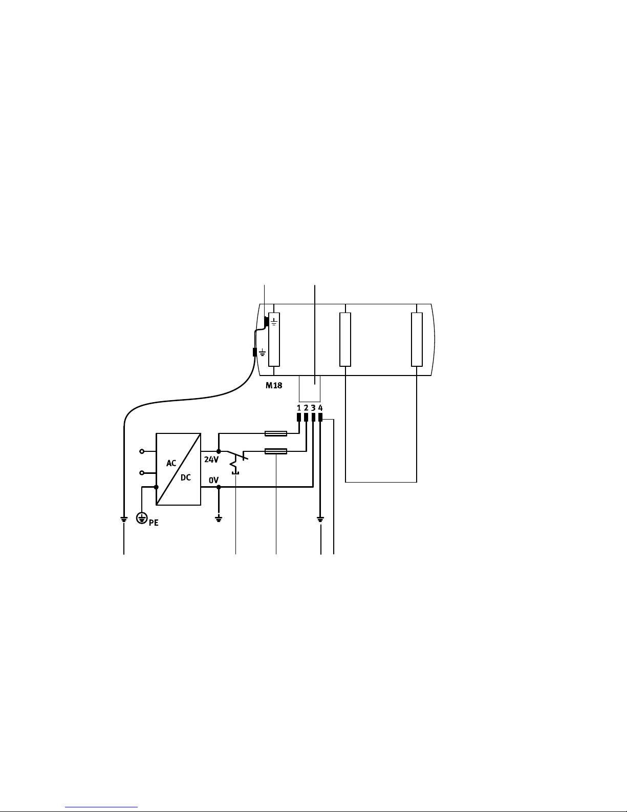
Electrical connection example
The diagram below shows as an example the connection of a common power supply for supplying
power to the electronics/sensors and the actuators. Observe the following:
– Maintain the tolerance of the load supply voltage (24 V DC U
OUT/A
+10/-25 %).
– Connect the earth terminals for potential equalisation and ensure that compensating currents are
prevented.
– Connect the load voltage so it can be switched off separately.
– Secure operating voltage and load voltage separately. Choose external fuses, depending on the
application. Take into account the current consumption of the products in design and protection of
the power supply. Pay attention to the maximum permitted current load (power rating per pin):
16 A. Note that the sum of both currents of the operating and load voltages flows over Pin 3 (“0 V”).
Pay attention to correct polarity.
12
456
3
4
1 Potential equalisation between the earth
terminal of the left-hand pneumatic base
plate and the left end plate of the electrical
interlinking module.
2 System supply
3 Earth terminal on pin 4, rated for max. 16 A
4 Potential equalisation of functional earth (FE)
5 External fuses
6 Separately switchable actuator technology
supply
Fig. 3.6 Example – connecting a common 24 V power supply and the potential equalisation
Page 25

4 Commissioning
Festo – MSE6-E2M-IN-EN – 2017-07c – English 25
4 Commissioning
Warning
Risk of injury
Stopping the controller (e.g. after the transmission of parameters, system configuration
or control program) interrupts the communication to the MSE6-E2M, and the shut-off
valve then switches to the initial position (pressurise). If the valve was previously
closed, the system is pressurised. If the system was vented, pressurisation takes place
suddenly.
Use appropriate measures to ensure that unintentional pressurisation of the system
is not possible.
Warning
Risk of injury
If the load or operating voltage of the MSE6-E2M is switched off, then the shut-off valve
switches to the initial position (pressurise). If the valve was previously closed, the sys
tem is pressurised. If the system was vented, pressurisation takes place suddenly.
Use appropriate measures to ensure that unintentional pressurisation of the system
is not possible.
The MSE6-E2M is equipped with a pneumatically-piloted shut-off valve. With preset parameters and
applied input pressure P1, the valve automatically switches to the “pressurise” status in the following
cases:
– Switch-off of the operating voltage or the load voltage
– Interruption of the network communication with correspondingly set system parameters
– Stopping of the higher-order controller (see manufacturer's specifications), e.g. in the case of trans
mission of control programs, parameters, configuration data.
Page 26
4 Commissioning
26 Festo – MSE6-E2M-IN-EN – 2017-07c – English
4.1 Approach
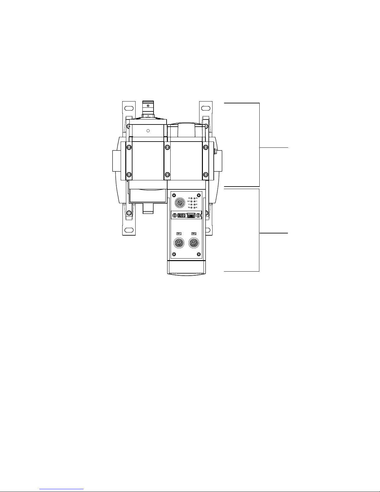
In order to avoid connecting and addressing errors, you should carry out commissioning in steps as
follows. The individual commissioning steps are shown in the diagram below.
1
2
1 Step 1 – Checking of the connected pneumatic application
2 Step 2 – Commissioning on the fieldbus with testing of the address allocation
Fig. 4.1 Commissioning steps (example at the bus node CPX-FB33)
Page 27
4 Commissioning
Festo – MSE6-E2M-IN-EN – 2017-07c – English 27
4.2 Prior to commissioning
Proceed with preparation as follows:
1. Check the pneumatic tubing connection of the MSE6-E2M.
2. Check the electric cabling of the MSE6-E2M.
3. Check the DIL switch settings of your MSE6-E2M, if necessary.
The characteristics of the MSE6-E2M can be adapted to various requirements. You can
carry out important settings as follows:
through DIL switches directly at the bus node (information on this can be found in
the brief description of the bus nodes è Tab. 1)
via parameterisation (for information consult chapter 7 of the system description
concerning the energy efficiency module (è MSE6-E2M-SY-…).
The DIL switches and the parameters are preset at the factory.
Caution
Incorrectly set parameters and DIL switches and parameters can cause damage during
operation. You must observe the following notes in order to prevent damage.
Check the DIL switch settings before using or replacing a MSE6-E2M.
Page 28
4 Commissioning
28 Festo – MSE6-E2M-IN-EN – 2017-07c – English
4.3 Brief instructions for commissioning
Detailed information on commissioning can be found in Chapter 4 of the system descrip
tion for the energy efficiency module (è MSE6-E2M-SY-…) as well as in the description
for the bus node (è Tab. 1) .
Use the current device description file file for your system. The current version is available
in the Festo Support Portal (è www.festo.com/sp).
1. Switch on the power supply to the service units and the controller (PLC).
2. Call up the controller software.
3. Download the device description file from the Festo Support Portal (GSD-, GSDML- or ESD-file,
depending on the network).
4. Connect the device description file to the controller.
5. Activate the network scanner or open the hardware catalogue.
6. Transfer the MSE6-E2M and the bus node from the hardware catalogue into the controller software
(detailed information on the topic can be found in the documentation for the higher-order controller).
The module consists of two single modules. The bus node must be selected as slave as
the first module (m). Then, the energy efficiency module must be loaded into the control
configuration as the second module (m+1).
The module number 1 is always automatically assigned to the MSE6-E2M and the mod
ule number 0 to the bus node.
7. Configure the MSE6-E2M (e.g. make settings for network interfaces).
You can find detailed information in the documentation for the higher-order controller.
8. Parameterise the MSE6-E2M (e.g. upper flow limit).
Basic information on the different parameters can be found in Chapter 7. A detailed de
scription of the parameters can be found in Chapter 7 of the system description for the
energy efficiency module (è MSE6-E2M-SY-…).
9. Check ready status.
If commissioning is successful, the following LEDs light up green: PS, PL. The following LEDs are
illuminated when the respective port is used: TP1, TP2. The remaining LEDs do not light up.
Page 29
4 Commissioning
Festo – MSE6-E2M-IN-EN – 2017-07c – English 29
4.4 Options for parameterisation
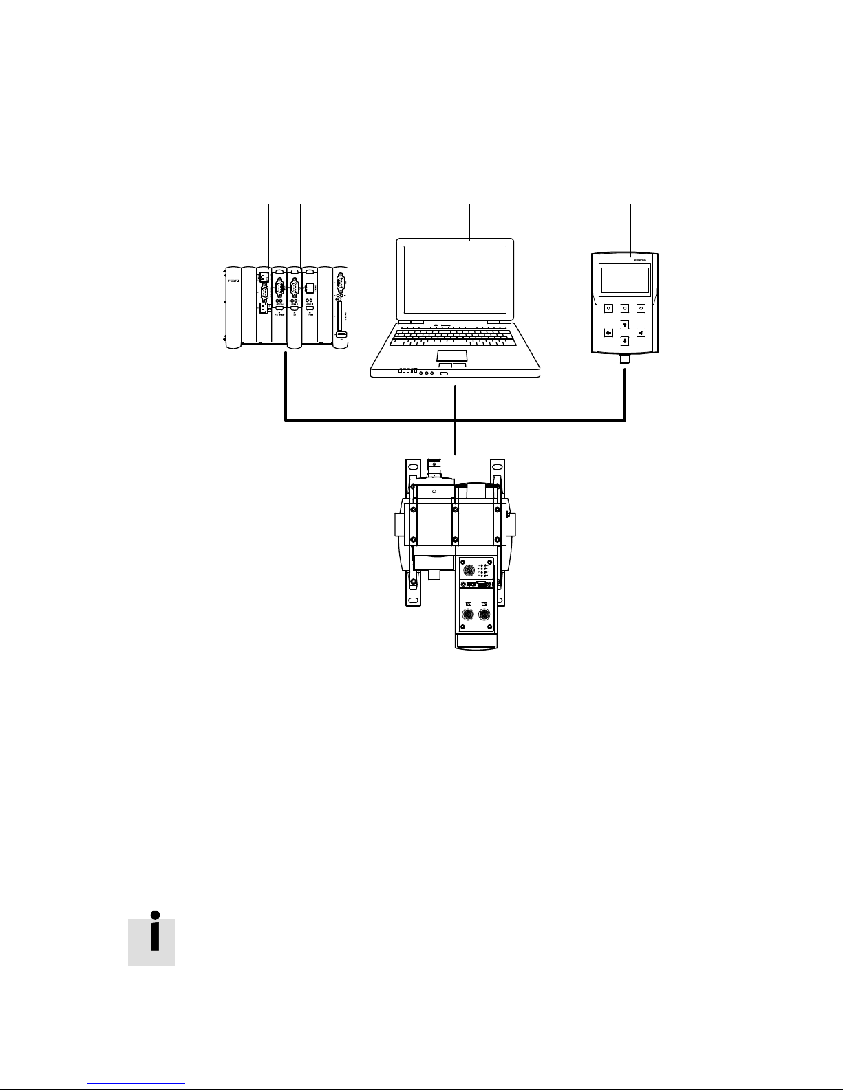
The parameterisation of the MSE6-E2M can be undertaken as follows, depending on the fieldbus pro
tocol used:
12 3 4
1 Interface module or network scanner/bus
master; the desired parameterisation can be
guaranteed, e.g. in the start-up phase or
after fieldbus interruptions.
2 User program in the higher-order PLC/IPC;
parameters can be modified during
operation.
3 Network-specific configurators; parameters
can be modified during the commissioning
phase or during troubleshooting.
4 Operator unit; parameters can be modified
during commissioning or during
troubleshooting.
Fig. 4.2 Options for parameterisation (as an example at the bus node CPX-FB33)
4.5 Start-up behaviour
Information on the topic of start-up behaviour can be found in Chapter 4 of the system
description for the energy efficiency module (è MSE6-E2M-SY-…).
Page 30

5 Measurement and control functions
30 Festo – MSE6-E2M-IN-EN – 2017-07c – English
5 Measurement and control functions
Information on the topic of measurement and control functions can be found in Chapter 5
of the system description for the energy efficiency module (è MSE6-E2M-SY-…).
Page 31
6 Input/output data
Festo – MSE6-E2M-IN-EN – 2017-07c – English 31
6 Input/output data
6.1 Overview
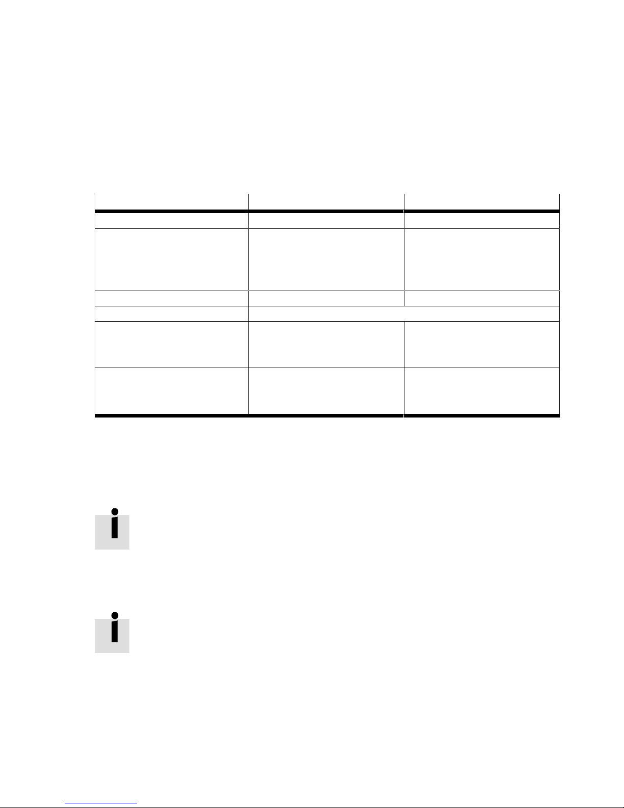
The MSE6-E2M possesses multiple functional module data, which can be replaced with the higher-or
der controller using the I/O data presented below.
Data field for Input word
1)
Output word
1)
Flow measurement Em.0 –
Consumption measurement
– Measured value
– Function status
– Control/operation
Em.1
Em.3
–
–
–
Am.0
Pressure measurement Em.2 –
Pressure change measurement Via selectable input data è Section 6.3
Blocking function
– Function status
– Control/operation
Em.3
–
–
Am.0
Selectable input data
– Input address
– Input data
Em.4
Em.5
Am.1 (è Section 6.3)
–
1) m = 1
Tab. 6.1 Overview of I/O data
6.2 Description of the I/O data
Information on the topic of description of I/O data can be found in Chapter 6.2 of the
system description for the energy efficiency module (è MSE6-E2M-SY-…).
6.3 Function selectable input data
Information on the topic of function selectable input data can be found in Chapter 6.3 of
the system description for the energy efficiency module (è MSE6-E2M-SY-…).
Page 32
7 Parameterisation
32 Festo – MSE6-E2M-IN-EN – 2017-07c – English
7 Parameterisation
Detailed information on parameterisation can be found in Chapter 7 of the system de
scription for the energy efficiency module (è MSE6-E2M-SY-…).
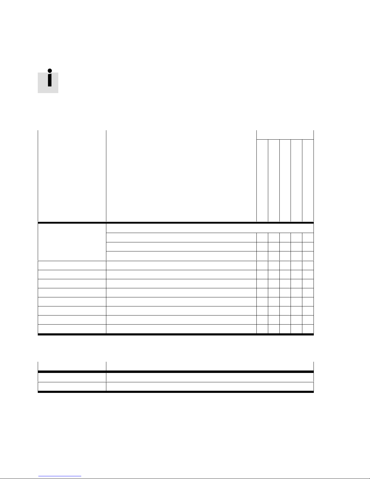
The following tables offer an overview of the module parameters of the function module. A distinction is
made between “Changeable module parameters” and “Read-only module parameters”.
Function no.
1)
Changeable module parameters Function
Flow measurement
Consumption measurement
Pressure measurement
Pressure change
Blocking function
4828 + m * 64 + 0
Monitoring
Bit 2: Undervoltage in actuator supply
– – – – n
Bit 6: Limit values
n – n n –
Bit 7: Parameterisation errors
n n n n n
4828 + m * 64 + 7 Diagnostics limit values startup n – n – –
4828 + m * 64 + 8 Units n n n n –
4828 + m * 64 + 10 Pressure change sample time – – – n –
4828 + m * 64 + 11…12 Upper limit flow n – – – –
4828 + m * 64 + 13…14 Upper limit pressure – – n – –
4828 + m * 64 + 15…16 Upper limit pressure change – – – n –
4828 + m * 64 + 17…18 Auto shut-off delay – – – – n
4828 + m * 64 + 19…20 Auto shut-off flow limit – – – – n
1) m = Module number (1)
Tab. 7.1 Overview - changeable module parameters
Function no.
1)
Read-only module parameters
4828 + m * 64 + 29…30 Module operating time
4828 + m * 64 + 31…32 Shut-off valve switching cycles
1) m = Module number (1)
Tab. 7.2 Overview - Read-only module parameters
Page 33
8 Diagnostics and error handling
Festo – MSE6-E2M-IN-EN – 2017-07c – English 33
8 Diagnostics and error handling
Detailed information on the topic of diagnostics and error handling can be found in
Chapter 8 of the system description for the energy efficiency module
(è MSE6-E2M-SY-…).
8.1 Summary of diagnostics options
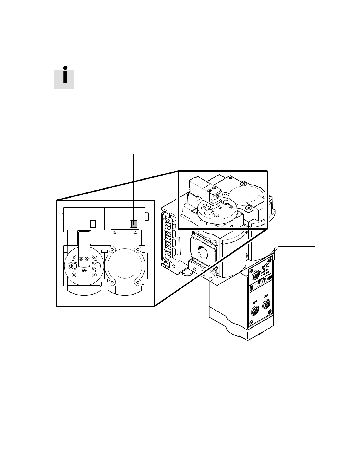
The MSE6-E2M offers comprehensive options for diagnostics and error handling. The following options
are available (è also Tab. 8.1):
3
1
2
1
1 On the spot diagnostics via LED
2 On the spot diagnostics via the operator unit
3 Diagnostics via the fieldbus
Fig. 8.1 Diagnostics options (as an example at the bus node CPX-FB33)
Page 34

8 Diagnostics and error handling
34 Festo – MSE6-E2M-IN-EN – 2017-07c – English
Diagnostics options Description Additional
information
1 On-site via LEDs The LEDs on the module display hardware errors,
bus errors, etc.
(è 8.2)
2 On-site via the operator
unit
The operator unit:
– Shows current error messages in plain text
– Offers access to the diagnostic memory.
Description of
CPX-MMI
operator unit
(è Tab. 1)
3 System status scanning
over the network (status
bits scanning)
The 8 status bits display common diagnostic
messages (global error message).
(è 8.3)
System diagnostics
through the network (via
the I/O diagnostic
interface)
Internal diagnostics data can be read via the I/O
diagnostics interface. In this way, detailed
diagnostic information can be accessed, even if
the network used does not offer any extensive
network-specific diagnostic functions.
The I/O diagnostic interface offers:
– Access to the current error message
– Access to the diagnostic memory
– Read access to internal parameters and data.
(è 8.3)
Network-specific
diagnostic functions
Diagnostic functions or communication services
e.g. DPV1 (PROFIBUS)
Description of
bus node
(è Tab. 1)
Tab. 8.1 Diagnostics options
8.2 On the spot diagnostics via LED
Information on the topic of on-the-spot diagnostics can be found in Chapter 8.2 of the
system description for the energy efficiency module (è MSE6-E2M-SY-…).
8.3 Diagnosis via status bits or the I/O diagnostic interface
Information on the topic of diagnostics through status bits or the I/O diagnostics inter
face can be found in Chapter 8.3 of the system description for the energy efficiency mod
ule (è MSE6-E2M-SY-…).
Page 35
8 Diagnostics and error handling
Festo – MSE6-E2M-IN-EN – 2017-07c – English 35
8.4 Error numbers
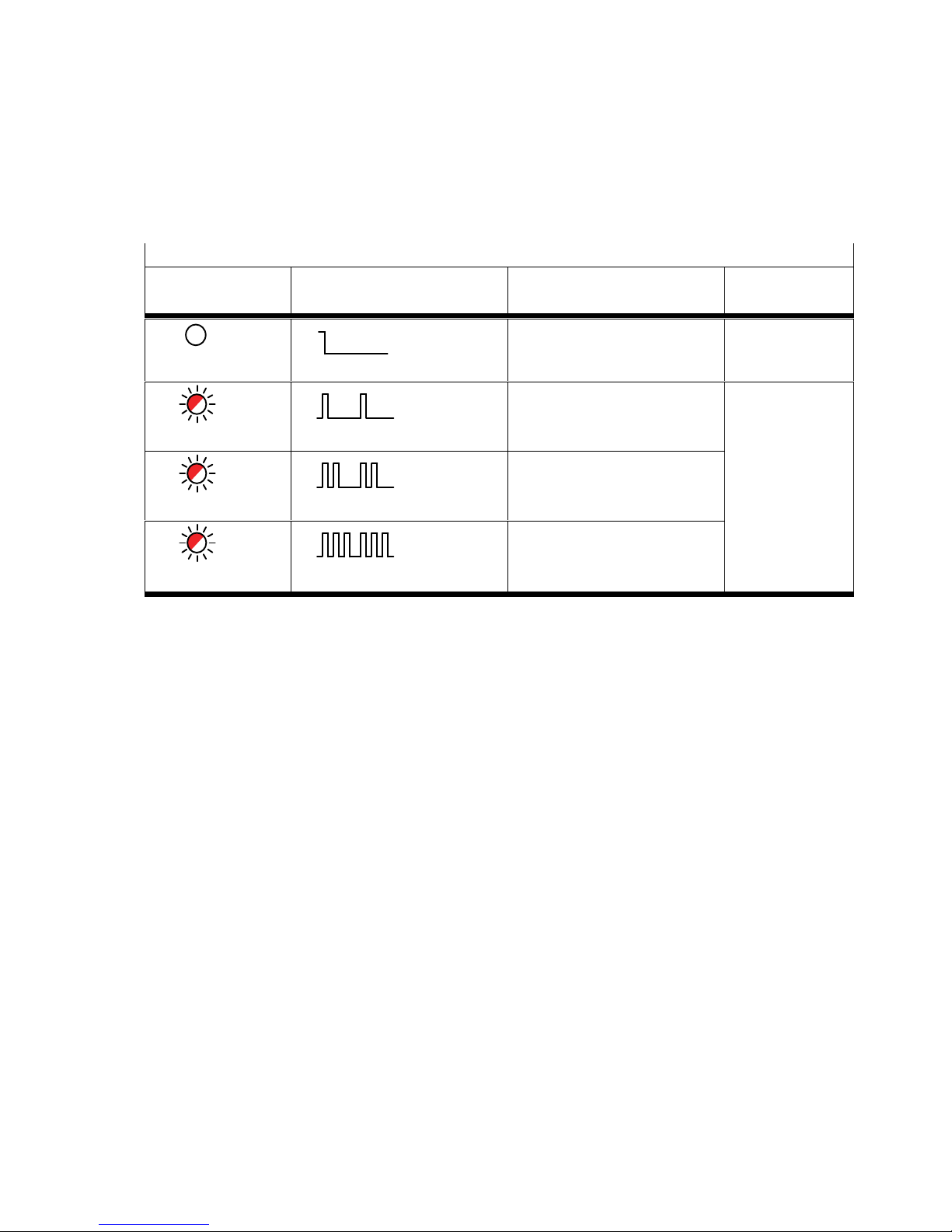
Possible errors of the MSE6-E2M are divided into three error classes with different priority, depending
on the seriousness of the error. If an error occurs, the system error LED (SF LED) will flash depending on
the error class.
SF (System Failure) – system fault
LED (red) Sequence
1)
Status Significance/
error handling
LED not illuminated
ON
OFF
No error –
LED flashes
ON
OFF
Simple error/information
(error class 1)
An overview of
all error num
bers can be
found in the de
scription for the
CPX terminal
(è Tab. 1)
LED flashes
ON
OFF
Error
(error class 2)
LED flashes
ON
OFF
Serious error
(error class 3)
1) The system error LED flashes, depending on the error class.
Error class 1 (simple error): 1 * flash, pause
Error class 2 (error) 2 * flash, pause
Error class 3 (serious error): 3 * flash, pause
Tab. 8.2 LED SF
If several errors occur together, the error with the highest priority will have precedence. This means
that:
– The system error LED flashes according to the higher priority
– The number of the error with the higher priority will be entered in the system diagnostic data under
function number 1938 (error number).
Within an error class, errors of modules with a lower module number have higher priority. For example,
errors of module number 0 have the highest priority within an error class. Errors of module number 1
have the second highest priority, etc.
Page 36
8 Diagnostics and error handling
36 Festo – MSE6-E2M-IN-EN – 2017-07c – English
Note
The following covers only module-specific errors. An overview of all possible error mes
sages, incl. those of the bus nodes, can be found in Chapter 8 of the system description
for the energy efficiency module (è MSE6-E2M-SY-…).
The following errors can be reported:
Error no.
Description
0 No error or end of a message status
10 Upper limit exceeded [Upper limit exceeded]
1)
15 Module/channel failed
2)
25 Error in parameterisation of the upper limit
[Fault in parametrizing upper limit]
1)3)
26 Undervoltage in actuator supply [Fault in actuator supply]
1)
29 Error in parameterisation [Fault in parametrizing]
1)3)
1) With active monitoring, the module displays the relevant error, depending on the parameterisation. However, the input signals will
be processed further.
2) All the electrical module functions are stopped.
3) The parameter values entered will be ignored; the module operates internally with the last valid parameter values.
Tab. 8.3 Error numbers
Page 37

A Technical appendix
Festo – MSE6-E2M-IN-EN – 2017-07c – English 37
A Technical appendix
A.1 Technical data
MSE6 -E2M
Operating pressure [bar]
[MPa]
4 … 10
0.4 … 1
Operating pressure,
Overload range
[bar]
[MPa]
10 … 12
1 … 1.2
Operating medium
1)
Compressed air to ISO 8573-1:2010 [7:4:4]
Nitrogen
Note on the operating medium Lubricated operation not possible
Temperature of medium [°C] 0 … 50
Mounting position Horizontal ±5°
Standard nominal flow rate
2)
1 } 2
In main flow direction
[l/min.] 4500
Standard nominal flow rate
2)
2 } 1
In relief direction
[l/min.] 4500
3)
Product weight [g] Max. 3500
Operating voltage supply
Electronics/sensor
– Nominal voltage [V DC] 24 ±25 %
– Current consumption at 24 V [mA] Max. 300
Actuator technology load
voltage supply
– Nominal voltage [V DC] 24 –25 %/+10 %
– Current consumption [mA] Typ. 100 E2M-function module
+ typ. 70 if shut-off valve in the blocking state
+ typ. intrinsic current consumption of the corresponding
bus node (è Tab. 1 )
– Undervoltage diagnostic
message (trigger level
without hysteresis)
[V] 15 … 17
Pressure sensor
5)
– Pressure measuring range [bar]
[MPa]
0 … 14
0 … 1.4
– Accuracy [%FS] typ. ±3
– Repetition accuracy [%FS] ±0.3
Page 38

A Technical appendix
38 Festo – MSE6-E2M-IN-EN – 2017-07c – English
MSE6 -E2M
Flow sensor
5)6)
– Flow direction Unidirectional P1 } P2
– Flow measuring range [l/min.] 50 … 5000
– Accuracy of flow rate ± (3 % of the measured value + 0.3 % FS)
– Repetition accuracy, zero
point
[%FS] ±0.2
– Repetition accuracy, range [%FS] ±0.8
– Temperature coefficient of
margin
[%FS/K] typ. 0.1
– Pressure-dependent margin [%FS/bar]
[%FS/MPa]
±0.5
±5
Shut-off valve
– Switch-on pressure [bar]
[MPa]
4
0.4
– Switch-off pressure [bar]
[MPa]
1
0.1
– Residual pressure [bar]
[MPa]
1
0.1
Degree of protection in accord
ance with EN 60529
IP65
4)
Electromagnetic compatibility
– Emitted interference è Declaration of conformity (www.festo.com)
– Interference immunity è Declaration of conformity (www.festo.com)
Vibration and shock
(in accordance with IEC 60068)
7)
– Vibration (part 2-6) SL1
– Shock (part 2-27) SL1
1) Lubricated operation not possible
2) Measured at p1 = 6 bar and p2 = 5 bar, Δp = 1 bar
Measured at p1 = 0.6 MPa and p2 = 0.5 MPa, Δp = 0.1 MPa
3) Shut-off valve in the “Pressurise” status
4) Plug connector inserted or fitted with protective cap
5) %FS = percent of the measurement value range end value (fullscale)
6) Typical accuracy with nominal conditions (6 bar (0.6 MPa), 23 °C and horizontal mounting orientation)
7) Explanations of the severity levels è Tab. A.2.
Tab. A.1 Technical Data
Page 39

A Technical appendix
Festo – MSE6-E2M-IN-EN – 2017-07c – English 39
Vibration load
Frequency range [Hz] Acceleration [m/s²] Deflection [mm]
SL1 SL2 SL1 SL2 SL1 SL2
2…8 2…8 – – ±3.5 ±3.5
8…41 8…27 10 10 – –
41…58 27…60 – – ±0.15 ±0.35
58…160 60…160 20 50 – –
160…200 160…200 10 10 – –
Shock load
Acceleration [m/s²] Duration [ms] Shocks per direction
SL1 SL2 SL1 SL2 SL1 SL2
±150 ±300 11 11 5 5
Continuous shock load
Acceleration [m/s²] Duration [ms] Shocks per direction
±150 6 1000
Tab. A.2 Values for vibration and shock in accordance with IEC 60068
Page 40

A Technical appendix
40 Festo – MSE6-E2M-IN-EN – 2017-07c – English
A.2 Connecting cable
Connecting cable (fieldbus/network cable)
Use a suitable cable for your fieldbus system. Take the cable type from the description for the respect
ive bus node. Also take into account here the distance and the fieldbus baud rate.
Connecting cable
Use a connecting cable with a sufficient cable cross-section. Avoid long distances between the power unit
and the MSE6-E2M. Long cables reduce the voltage supplied by the power supply unit.
Preparing the connecting cable
Caution
The position of the pins on the plug connector is different from that on the socket!
– For pin allocation of the fieldbus interface, see description for the respective field
bus node.
– The operating voltage and load voltage connections are in the form of plug connect
ors. Information on the pin allocation can be found in the following chapters.
Use plug connectors and sockets from the Festo product range which match the outside
diameter of the cables used.
Connect the plugs and cables as follows (example):
1. Open the plugs/sockets as follows:
– Power supply socket:
Insert the mains power socket into the operating voltage connection of the MSE6-E2M.
Unscrew the housing of the socket.
Then remove the connecting part of the socket, which is inserted in the operating voltage
connection.
Page 41
A Technical appendix
Festo – MSE6-E2M-IN-EN – 2017-07c – English 41
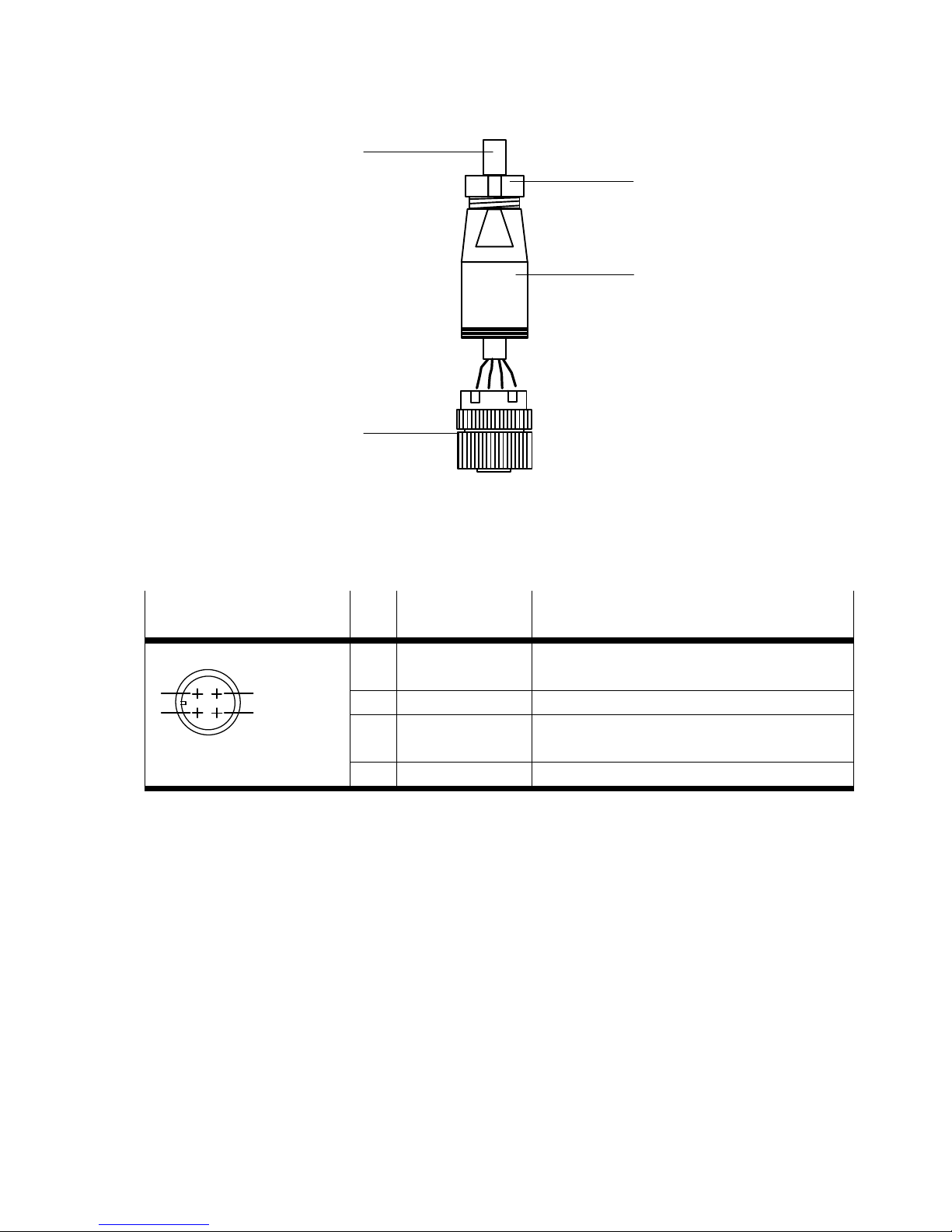
1
2
3
4
1 Cable
2 Strain relief
3 Housing
4 Connecting part
Fig. A.1 Component parts of the socket and cable throughfeed
Plug connector
(Top view of device)
Pin System supply Function
M18
1
2
3
4
1 24 V DC U
EL/SEN
Operating voltage supply for the electronics
and sensors
2 24 V DC U
OUT/A
Load voltage supply for actuators
3 0 V U
EL/SEN
/
0 V U
OUT/A
Operating load voltage
4 FE Functional earth
Tab. A.3 Pin allocation, system supply
2. Open the strain relief on the rear part of the housing. Then pass the cable through.
3. Remove 5 mm of insulation from the end of the conductors and fit wire end sleeves on the stranded
wires.
4. Connect the ends of the conductors.
5. Replace the connecting part on the housing of the plug connector/socket. Pull the cable back so
that there are no loops inside the housing.
6. Tighten the strain relief.
Page 42

B Glossary
42 Festo – MSE6-E2M-IN-EN – 2017-07c – English
B Glossary
Term/abbreviation Significance
Bus node Creates the communicative connection to a higher-order controller
through a fieldbus, passes on the control signals to the integrated sensor
module and monitors their functioning.
CPX Automation platform
DIL switches Dual-in-line switches consist of several switch elements with which
settings can be made.
I Input
I/O diagnostic interface The I/O diagnostic interface is a bus-independent diagnostic interface at
I/O level that permits access to internal data of the MSE6-E2M.
I/Os Inputs and outputs
O Output
PLC/IPC Programmable logic controller/industrial PC
Status bits Internal inputs that supply coded common diagnostic messages.
Tab. B.1 Product-specific terms and abbreviations
Page 43

MSE6-E2M
Festo – MSE6-E2M-IN-EN – 2017-07c – English 43
Index
A
Abbreviations 42..........................
C
Cable
– Pre-assemble connecting cable 40..........
– Select fieldbus cable 40..................
– Select operating voltage cable 40...........
CE marking 8.............................
Changeable module parameters 32...........
Commissioning
– Profibus 28............................
– Start-up behaviour 29....................
Current
– External fuse protection 23................
–Fuse 22...............................
D
Diagnostic memory 13.....................
Diagnostics
– On-site 34.............................
– Via fieldbus 34..........................
E
Earthing, Potential equalisation 23...........
EMERGENCY OFF concept 22................
Error numbers 34, 35......................
Example of connection, Electrical 24..........
F
Functional earth 23........................
Fuse 23.................................
I
I/O diagnostics interface 13.................
Input data, Selectable 31...................
Intended use 6...........................
N
Notes on the description 5..................
O
Operating voltage 24......................
P
Pin allocation, System supply 41.............
Potential equalisation 23...................
R
Read-only module parameters 32............
S
Safety instructions, General 6...............
Status bits 13............................
T
Technical data 37.........................
V
Voltage, Connect 22.......................
Page 44

MSE6-E2M
44 Festo – MSE6-E2M-IN-EN – 2017-07c – English
Page 45

Page 46

Reproduction, distribution or sale of this document or communica
tion of its contents to others without express authorization is
prohibited. Offenders will be liable for damages. All rights re
served in the event that a patent, utility model or design patent is
registered.
Copyright:
Festo AG & Co. KG
Postfach
73726 Esslingen
Germany
Phone:
+49 711 347-0
Fax:
+49 711 347-2144
E-mail:
[email protected]
Internet:
www.festo.com
Original: de
 Loading...