


Valveterminaltype03
Electronics
manual
Valve terminal with
field bus protocol:
INTERBUS optical
fibre waveguide
remote bus
“Rugged-Line”
type IFB21-03
Manual
191 085
en 0010a


Contents and general instructions
Author E. Klotz, M. Simons..........................
Editors H.–J. Drung, M.Holder........................
Oridinal de.......................................
Layout Festo AG & Co., Dept. KG-GD...................
Type setting DUCOM................................
Edition 0010a.....................................
Title MANUAL-EN..................................
Designation P.BE-VIFB21-03-EN......................
Order no. 191 085.................................
E (Festo AG & Co., D–73726 Esslingen,
Federal Republic of Germany, 2000)
Internet: http://www.festo.com
E-mail: service_international@festo.com
The copying, distribution and utilization of this document as
well as the communication of its contents to others without
expressed authorization is prohibited. Offenders will be held
liable for the payment of damages. All rights reserved, in
particular the right to carry out patent, utility model or
ornamental design registration.
Fest o P.BE-VIF B21-03-E N en 0010a
I

Contents and general instructions
II
Festo P.BE-VIFB21-03-EN en 0010a

Contents and general instructions
Contents
Designated use VII........................................................
Target group VIII..........................................................
Service VIII...............................................................
Important user instructions IX..............................................
Abbreviations XI.........................................................
Manualsonthisvalveterminal XIII............................................
1. Summary of components 1-1........................................
1.1 Summary of multi-functional Festo valve terminals 1-3....................
1.2 Description of the components 1-4....................................
1.2.1 Elektric modules 1-4................................................
1.2.2 Pneumatic MIDI modules 1-5.........................................
1.2.3 Pneumatic MAXI modules 1-6........................................
1.3 Method of operation 1-7............................................
2. Fitting 2-1........................................................
2.1 Fitting the modules and components 2-3...............................
2.1.1 Earthing the end plates 2-4..........................................
2.2 Fitting the valve terminal onto a hat rail 2-6.............................
2.3 Fitting the valve terminal onto a wall 2-9...............................
3. Installation 3-1...................................................
3.1 Installation summary 3-3............................................
3.1.1 System structure on the remote bus 3-3................................
3.1.2 Installation instructions 3-5..........................................
3.2 Bus node 3-6......................................................
3.2.1 Configuration settings in the node 3-9.................................
3.3 Connecting the power supplies 3-11....................................
3.3.1 Calculating the current consumption 3-12...............................
3.3.2 Connecting the power supply 3-14.....................................
3.4 INTERBUS interface 3-22.............................................
3.4.1 Conecting the optical fibre waveguide Rugged-Line plug 3-23...............
Festo P.BE-VIFB21-03-EN en 0010a
III

Contents and general instructions
4. Commissioning 4-1................................................
4.1 Configuring and addressing the valve terminal 4-3.......................
4.1.1 Ascertaining the configuration data 4-3................................
4.1.2 Calculating the number of inputs/outputs 4-5...........................
4.1.3 Address assignment of the valve terminal 4-6...........................
4.1.4 Address assignments after extension/conversion 4-12.....................
4.2 INTERBUS – Configuring and addressing the bus 4-14.....................
4.2.1 General commissioning instructions 4-14................................
4.2.2 Configuring the bus with CMD software 4-16.............................
4.2.3 Configuring the bus without CMD software 4-25..........................
4.2.4 Addressing the inputs and outputs 4-27.................................
4.2.5 Entering process data via the CMD software 4-30.........................
4.2.6 Status bits 4-34.....................................................
4.2.7 Other instructions 4-36...............................................
5. Diagnosis and error treatment 5-1....................................
5.1 Summary of diagnostic possibilities 5-3................................
5.2 On-the-spot diagnosis 5-4...........................................
5.2.1 Bus node 5-4......................................................
5.2.2 LED modules 5-6...................................................
5.2.3 On-the-spot error treatment 5-9......................................
5.2.4 Status bits 5-10.....................................................
5.3 Diagnosis via INTER BUS 5-13.........................................
5.3.1 Reaction to faults in the control system 5-17.............................
A. Technical Appendix A-1.............................................
A.1 Technical specifications A-3..........................................
A.2 Cable length A-6...................................................
A.3 Examples of circuitry A-11............................................
A.3.1 Power supply connection A-11.........................................
IV
Festo P.BE-VIFB21-03-EN en 0010a

Contents and general instructions
B. Accessories B-1...................................................
B.1 Connecting the cables to the plugs (sensors/outputs) B-3.................
B.2 Phoenix Contact accessories B-5......................................
B.2.1 Connecting the cables to the Rugged-Line plug B-6.......................
C. Index C-1.........................................................
C.1 Index C-3.........................................................
Festo P.BE-VIFB21-03-EN en 0010a
V

Contents and general instructions
VI
Festo P.BE-VIFB21-03-EN en 0010a

Contents and general instructions
Designated use
The valve terminal described in this documentation is designed for use only as follows:
– for controlling pneumatic and electric actuators
– for interrogating electric sensor signals through
Please use the valve terminal only as follows:
–asdesignated
– in faultless technical condition
– without undertaking any modifications.
If the valve terminal is used in conjunction with additional
commercially-available components, such as sensors and
actuators, make sure that the maximum specified limits for
pressures, temperatures, electrical data, torques, etc. are
observed.
(valves and output modules)
the input modules.
Festo P.BE-VIFB21-03-EN en 0010a
Please observe the standards mentioned in the relevant
chapters and comply with national and local technical regulations.
VII

Contents and general instructions
Additional modules for this valve terminal
The multifunctional valve terminal can be extended with the
following modules:
I/O modules
Type designation Name
VIGE-03-FB-... Input module with 4 or 8 inputs, PNP or NPN, 4-pin or 5-pin, with
VIGE-03-FB-16-SUBD-S Input module 16 inputs, PNP, 15-pin Sub-D connecting socket,
VIGA-03-FB-... Output module with 4 outputs, PNP or NPN, 4-pin or 5-pin
VIGV-03-FB-... Additional power supply module (24 V/25 A) for high-current out-
VIEA-03-FB-... Multi I/O module with 12 inputs and 8 outputs, PNP
VIA-03-FB-... Analogue I/O module with 3 inputs and 3 outputs
VIAP-03-FB Analogue I/O module with 1 input and 1 output
VIASI-03-M AS-interface master
or without electronic fuse.
with electronic fuse.
puts.
Target group
This manual is directed exclusively at personnel who are
trained in control and automation technology, and who have
experience in installing, commissioning, programming and
diagnosing programmable logic controllers (PLC) and field
bus systems.
Service
VIII
If you have any technical problems, please contact your local
Festo Service.
Festo P.BE-VIFB21-03-EN en 0010a

Contents and general instructions
Important user instructions
Danger categories
This manual contains notes on possible dangers which may
occur if the product is not used correctly. These notes are
marked (warning, caution, etc.), printed on a shaded background and also accompanied by a pictogram. A distinction is
made between the following types of danger instructions:
Warning
This means that serious injury to persons or damage to
property can occur if these instructions are not observed.
Caution
This means that injury to persons or damage to property
can occur if these instructions are not observed.
Festo P.BE-VIFB21-03-EN en 0010a
Please note
This means that damage to property can occur if these
instructions are not observed.
In addition, the following pictogram indicates passages in the
text which describe activities with electrostatically vulnerable
components:
Electrostatically vulnerable components: incorrect handling
can cause damage to components.
IX

Contents and general instructions
Marking special information
The following pictograms mark passages in the text containing special information.
Pictograms
Information:
Recommendations, tips and references to other sources of
information.
Accessories:
Details about necessary or useful accessories for the Festo
product.
Environment:
Information on the environmental-friendly use of Festo
products.
Text markin gs
S The bullet marks activities which may be carried out in
any desired order.
1. Numbers indicate activities which must be carried out in
the sequence stated.
– Hyphens indicate general items.
X
Festo P.BE-VIFB21-03-EN en 0010a

Contents and general instructions
Abbreviations
The following product-specific abbreviations are used in this
manual:
Abbreviation Meaning
Terminal or valve terminal Valve terminal type 03 with/without electric I/Os
Node Field bus node
Manifold
Single manifold
Double manifold
I
O
I/O
P-module Pneumatic module in general
I/O module Module with digital inputs or outputs in general
PLC Programmable logic controller; in brief: controller
Waveguide Interbus optic al fibre waveguide
RL-connection Rugged-line connection
Pneumatic manifold for two valves
Manifold for two single-solenoid valves
Manifold for two double-solenoid or mid-position valves
Input
Output
Input/output
Fig. 0/1: List of abbreviations
Festo P.BE-VIFB21-03-EN en 0010a
XI

Contents and general instructions
Please note
A simplified representation of valve terminal type 03 with
four pneumatic manifolds and four input/output modules
(standard fitting) is used for most drawings in this manual.
1 Ein-/Aus-
gangsmodule
2 Feldbusknoten
3 Ventile
4 Ungenutzter Ven-
tilplatz
12 34
Fig. 0/2: Standard fitting for the drawings
XII
Festo P.BE-VIFB21-03-EN en 0010a

Contents and general instructions
Manuals on this valve terminal
The following Festo manuals will be required to complete the
documentation for the modular valve terminal, depending on
your order and on the equipment fitted on your system:
designation
P.BE-MIDI/MAXI-03-... Pneumatics manual
P.BE-VIEA-03...05-.. Supplementary manuals for I/O modules
P.BE-VIAX-03...05-... Analogue I/Os manual
P.BE-VIASI-03...05-... AS-i master manual
P.BE-VIFB21-03-... Electronics manual
Title/product
– Valve terminal type 03, MIDI/MAXI
(digital I/O modules 4 I, 8 I, 4 O, high-current output modules, multi-I/O modules)
S Field bus connection FB21 (this man-
ual)
Fig. 0/3: Manuals on this valve terminal
Festo P.BE-VIFB21-03-EN en 0010a
XIII

Contents and general instructions
XIV
Festo P.BE-VIFB21-03-EN en 0010a

Summary of components
Chapter 1
1-1Festo P.BE-VIFB21-03-EN en 0010a

1. Summary of components
Contents
1. Summary of components 1-1........................................
1.1 Summary of multi-functional Festo valve terminals 1-3....................
1.2 Description of the components 1-4....................................
1.2.1 Elektric modules 1-4................................................
1.2.2 Pneumatic MIDI modules 1-5.........................................
1.2.3 Pneumatic MAXI modules 1-6........................................
1.3 Method of operation 1-7............................................
1-2
Festo P.BE-VIFB21-03-EN en 0010a

1. Summary of components
1.1 Summary of multi-functional Festo valve terminals
The multi-functional valve terminal consists of the following
individual modules and components:
Valve termial Description of the modules
Typ e 0 3
MIDI/MAXI and electric
modules
Electric modules (PNP or NPN) fitted with:
– digital inputs (modules with 4 or 8 inputs)
– digital outputs (modules with 4 outputs) 0.5 A
– high-current outputs 2 A
– multi-I/Os (module with 12 I/8 O) 0.5 A
– analogue I/Os, AS-i master (not possible with every node
Pneumatic modules fitted with:
– manifolds (MIDI and MAXI) fitted with 5/2-way solenoid valves,
5/2-way double solenoid valves, 5/3-way mid-position valves
(with auxiliary pilot air) or blanking plat es
– Special modules for additional pressure supply, intermediate
pressure supply, end plates with/without regulator
Fig. 1/1: Summary of the modules of the multi-functional Festo valve terminals
)
Festo P.BE-VIFB21-03-EN en 0010a
1-3

1. Summary of components
1.2 Description of the components
1.2.1 Elektric modules
The following connecting and display elements can be found
on the electric modules:
2 3 4 56 78
1
9
1 Inputsocketfortwoelectricinputs
(PNP or NPN
)
5 Green LED (per input)
6 Output socket for electric output (PNP)
2 Red LED (error display of input module
with electronic fuse)
3 Two green LEDs (one LED per input)
4 Input socket for an electric input (PNP
or NPN)
Fig. 1/2: Connecting and display elements of the electric modules
1-4
7 Yellow LED (status display per output)
8 Red LED (error display per output)
9 Further modules (e.g. additional
supply, high-current PNP/NPN)
Festo P.BE-VIFB21-03-EN en 0010a

1. Summary of components
1.2.2 Pneumatic MIDI modules
The following display and operating elements can be found
on the pneumatic MIDI modules type 03:
123
4
Yellow LEDs (per valve solenoid coil)
1
3 Valve location inscription field
(identification labels)
2 Manual override (per valve solenoid
coil, either spring-return or locking)
Fig. 1/3: Operating, display and connecting elements of MIDI modules type 03
Festo P.BE-VIFB21-03-EN en 0010a
4 Unused valve location with blanking-
plate
1-5

1. Summary of components
1
2
1.2.3 Pneumatic MAXI modules
The following display and operating elements can be found
on the pneumatic MAXI modules type 03:
3
45
Yellow LED (per valve solenoid coil)
1
4 Valve location inscription field
(identification labels)
2 Manual override (per valve solenoid
coil, either spring-return or locking)
5 Regulator for limiting the auxiliary pilot
air pressure
3 Unused valve location with blanking
plate
Fig. 1/4: Operating, display and connecting elements of MAXI modules type 03
1-6
Festo P.BE-VIFB21-03-EN en 0010a

1. Summary of components
5
1.3 Method of operation
The node controls the following functions:
– It connects the valve terminal to the INTER BUS and
– It controls the system settings of the terminal as
– It controls data transfer to/from the field bus module
– It manages the internal control of the terminal.
1 Incoming field
bus
to the power supply.
well as an automatic valve test and (in conjunction
with G3 modules) the display and masking out of
error messages.
of your control system.
12
2 Continuing field
bus
3 Compressed air
4 Node
5 Workair (2, 4)
4
Fig. 1/5: Method of operation of a valve terminal
Festo P.BE-VIFB21-03-EN en 0010a
3
1-7

1. Summary of components
The input modules control the processing of input signals
(e.g. from sensors) and pass these signals onto the controller
via the field bus.
The output modules are universal electric outputs and control
low-current consuming devices, e.g. further valves, bulbs,
etc.
Additional I/O modules for special applications are also available.
Further information on the use of all the I/O modules can be
found in the ”Supplementary manual for the I/O modules” for
your valve terminal.
The pneumatic modules provide the following:
– the common channels for the supply and exhaust air
1-8
– electric signals from all valve solenoid coils
Work connections 2 and 4 have been provided for each valve
location on the individual pneumatic modules.
The valves are supplied with compressed air via the common
channels on the pneumatic end plate or via special supply
modules. The exhaust air and pilot exhaust air are also
vented via these channels or modules. Further modules for
supplying pressure are also available, e.g. to enable you to
work with different working pressures.
Detailed information on the use of these modules can be
found in the ”Pneumatics manual” foryourvalveterminal.
Festo P.BE-VIFB21-03-EN en 0010a

Fitting
Chapter 2
Festo P.BE-VIFB21-03-EN en 0010a
2-1

2. Fitting
Contents
2. Fitting 2-1........................................................
2.1 Fitting the modules and components 2-3...............................
2.1.1 Earthing the end plates 2-4..........................................
2.2 Fitting the valve terminal onto a hat rail 2-6.............................
2.3 Fitting the valve terminal onto a wall 2-9...............................
2-2
Festo P.BE-VIFB21-03-EN en 0010a

2. Fitting
2.1 Fitting the modules and components
The valve terminal is supplied from the factory ready
mounted. If you wish to add or replace individual modules
and/or components, please refer to the following manuals:
”Supplementary manual for the I/O modules” for fitting the
–
electric I/O modules
–”Pneumatics manual” for fitting the pneumatic modules
– The fitting instructions are included in the package in the
case of modules and components ordered at a later
stage.
Please note
Treat all the modules and components of the valve
terminal with care. Pay attention in particular to the
following:
– The screws must fit exactly (otherwise the threads will
be damaged). Tighten the screws without distortion or
mechanical stress.
– Observe the specified torques.
– Modules must not be offset (IP 65).
– Connecting surfaces must be clean (avoid leakage and
contact faults).
– The contacts of type 03 valve solenoid coils must not be
bent (they are not resistant to bending and will break off
if bent back).
– Electrostatically vulnerable components.
Do not touch any contact surfaces on the side plug connectors of the modules and components.
Festo P.BE-VIFB21-03-EN en 0010a
2-3

2. Fitting
2.1.1 Earthing the end plates
The valve terminal possesses a left-hand and a right-hand
end plate as a mechanical termination of the valve terminal.
These end plates fulfil the following functions:
– They comply with protection classs IP 65.
– They contain connections/contacts for earthing.
– They contain holes for fitting the terminal onto a wall
and for the hat rail clamping unit.
Please note
When supplied from the factory, the end plates of the valve
terminal are earthed internally. If you carry out any extensions/conversions to the type 03 valve terminal, you must
earth the end plates of the terminal as described below. In
this way you will avoid faults caused by electromagnetic
influences.
2-4
Earth the end plates as follows:
1. Right-hand end plate:
To earth the right-hand end plate connect the pre-fitted
cable on the inside to the appropriate contacts on the
pneumatic modules or the node (see diagram below).
2. Left-hand end plate:
The left-hand end plate must be connected conductively to
the other components by means of t he pre-fitted spring
contacts.
Please note:
Instructions on earthing the complete valve terminal can be
found in the chapter ”Installation.” The diagram below shows
how both end plates are fitted.
Festo P.BE-VIFB21-03-EN en 0010a

2. Fitting
4
1 23
Seal
1
2 Contact for earth cable
Fig. 2/1: Fitting the end plates
Festo P.BE-VIFB21-03-EN en 0010a
3 Pre-fitted earth cable
4 Fastening screws max. 1 Nm
1
2-5

2. Fitting
2.2 Fitting the valve terminal onto a hat rail
The valve terminal is also suitable for fitting onto a hat rail
(support rail as per EN 50022). There is a guide groove on the
rear of all modules for hanging them on the hat rail (see Fig.
2/4).
Caution
– A hat rail fitting without a hat rail clamping unit is not
permitted.
– Iftheterminalisfittedinaslopingpositionorifitissub-
jected to vibration, secure the hat rail clamping unit
additionally against sliding down and unintentional
loosening/opening with the locking screws intended for
this purpose (item 3).
Please note
– If the terminal is fitted in a horizontal position and with a
permanent load, the hat rail clamping unit need not be
secured addititonally with locking screws (item 3).
– If the terminal does not have a hat rail clamping unit,
this can be ordered and fitted at a later date.
– WhetherMIDIorMAXIclampingunitsaretobeused,
dependsontheexistingendplates(MIDI/MAXI).
2-6
Hat-rail clamping unit
In order to fit the valve terminal onto a hat rail, you will require a hat-rail clamping unit. This must be fitted on the rear
of the end plates as shown in the diagram below.
Festo P.BE-VIFB21-03-EN en 0010a

2. Fitting
2
1
Pay attention to the following:
Before fitting
S The adhesive surfaces for the rubber feet must be clean
(clean with spirit).
S The flat-head screws must be tightened(item 3).
After fitting
S The levers must be secured with locking screws (item 7).
3
1
4
1 Lever
*)
2 O-ring
3 Flat-head screw
*)
different lever lengths for MIDI and MAXI
Fig. 2/2: Fitting the hat rail clamping unit
Festo P.BE-VIFB21-03-EN en 0010a
5
6
4 Rubber foot self adhesive
5 Clamping elements
6 Locking screw
2-7

2. Fitting
Please note
Observe the fitting space required due to the optical fibre
waveguide connections on the node.
Proceed as follows:
1. Ascertain the weight of your terminal as described in
chapter 2.2.
2. Make sure that the mounting surface can support this
weight.
3. Fit a hat rail (support rail as per EN 50022 - 35x15; width
35 mm, height 15 mm).
4. Fasten the hat rail to the fastening surface at least every
100 mm.
5. Hang the terminal onto the hat rail. Secure the terminal on
both sides with the hat rail clamping unit to prevent it
from tipping or sliding (see diagram below).
6. Iftheterminalisfittedinaslopingpositionorissubjected
to vibration, secure the hat rail clamping unit against
unintentional loosening/opening with two locking screws
(item 3).
1 Hat rail clamping
unit unlocked
2 Hat rail clamping
unit locked
3 Locking screw
12
Fig. 2/3: Fitting valve terminal type 03 onto a hat rail
2-8
33
Festo P.BE-VIFB21-03-EN en 0010a

2. Fitting
2.3 Fitting the valve terminal onto a wall
Caution
In the case of long terminals with several I/O modules, use
additiona l support bracket s (approxi m atel y every 200 mm).
You will then avoid:
– overloading the fastening eyes on the left-hand end
plate
– the terminal sagging (I/O side)
– natural resonances
Please note
Observe the fitting space required due to the optical fibre
waveguide connections on the node.
Proceed as follows:
1. Ascertain the weight of your terminal (weigh or calculate).
The following values are guidelines:
Modules of valve terminals
Typ e 0 3 *)
- per pneumatic module (incl. valves)
Node 1kg 1kg
I/O module 0.4 kg 0.4 kg
*) Components for height linking: weight see Pneumatics manual
Festo P.BE-VIFB21-03-EN en 0010a
MIDI
0.8 kg
MAXI
1.2 kg
2-9

2. Fitting
2. Make sure that the mounting surface can support this
weight and check to see if support brackets are required
for the I/O modules.
3. If necessary, use washers.
4. Fasten the valve terminal with four M6 screws on the left
and right-hand end plates. The terminal can be mounted
in any position.
2-10
Fig. 2/4: Fitting the terminal onto a wall
Festo P.BE-VIFB21-03-EN en 0010a

Installation
Chapter 3
3-1Festo P.BE-VIFB21-03-EN en 0010a

3. Installation
Contents
3. Installation 3-1...................................................
3.1 Installation summary 3-3............................................
3.1.1 System structure on the remote bus 3-3................................
3.1.2 Installation instructions 3-5..........................................
3.2 Bus node 3-6......................................................
3.2.1 Configuration settings in the node 3-9.................................
3.3 Connecting the power supplies 3-11....................................
3.3.1 Calculating the current consumption 3-12...............................
3.3.2 Connecting the power supply 3-14.....................................
3.4 INTERBUS interface 3-22.............................................
3.4.1 Conecting the optical fibre waveguide Rugged-Line plug 3-23...............
3-2
Festo P.BE-VIFB21-03-EN en 0010a

3. Installation
3.1 Installation summary
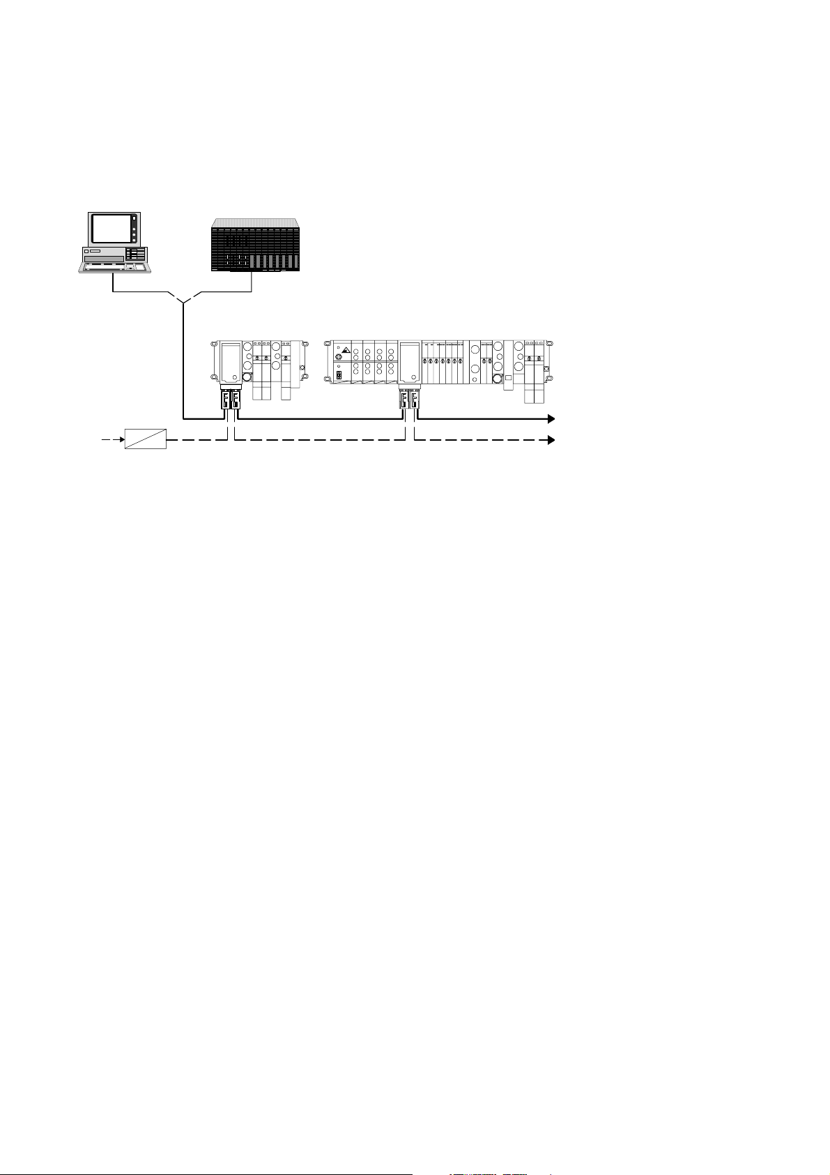
3.1.1 System structure on the remote bus
The multi-functional valve terminal type 03 with FB21 is an
optical fibre waveguide remote bus slave on the INTERBUS
with Rugged-Line connection technology. The terminal behaves on the remote bus like an optical fibre waveguide bus
terminal with integrated I/Os and must be addressed accordingly.
Please note
– Commissioning on the remote bus can only take place
when all the slaves have been fully connected.
– The valve terminal requires 24 V DC power supply. This
is supplied via the Rugged-Line plug. A separate supply
and separate switch off for the valve terminal outputs/
valves is possible.
Festo P.BE-VIFB21-03-EN en 0010a
3-3
3. Installation
1
1
23
230 VAC
24 VDC
1 INTERBUS master: PC or PLC with module
2 Valve terminal type 03: Only MA XI valves
3 Valve terminal type 03: M IDI/MAXI valves and electric modules
Fig. 3/1: Remote bus system structure with valve terminal
3-4
Festo P.BE-VIFB21-03-EN en 0010a

3. Installation
3.1.2 Installation instructions
The following sections and chapters contain information on
installation and on preparing commissioning.
– Settings in the relevant field bus node, if required.
– Calculating the current consumption of the valve terminal
and instructions on selecting suitable power units and
cables.
– Connecting the power supply and instructions on comply-
ing with EMC guidelines.
– Connecting the relevant bus system and instructions on
the bus cables.
The following supplementary information can be found in the
Appendix:
Festo P.BE-VIFB21-03-EN en 0010a
– Basic principles of cable length and cross sectional area
including calculation aids.
– Connecting the cables to the plug/socket.
– Accessories and sources of supply.
3-5

3. Installation
3.2 Bus node
Opening and closing the node
Warning
Before undertaking installation and/or maintenance work,
switch off the following:
S the compressed air supply
S the power supply for the electronics
S the load voltage supply for the outputs/valves
You can thereby avoid:
– uncontrolled movements of loose tubing
– undesired movements of the connected actuators
3-6
– undefined switching states of the electronics.
Caution
The node contains electrostatically vulnerable components.
S Do not therefore touch the contacts of these compo-
nents.
S Observe the regulations for handling electrostatically
vulnerable components.
You will then avoid damage to the electronics in the node.
Festo P.BE-VIFB21-03-EN en 0010a

3. Installation
1 Green LED
2 Red LED
3 Yellow LED
4 Fuse for power
supply to inputs
5 INTERBUS op-
tical fibre waveguide interface,
continuing
6 Power supply
connection, continuing
The following connecting and display elements can be found
on the cover of the node:
1
IB DIAG
RC
RD
F01
F02
US1
US2
9
2
3
4
7 Power supply
connection, incoming
8 INTERBUS op-
tical fibre waveguide interface,
incoming
9 Philips screw
Fig. 3/2: Cover of the node
Festo P.BE-VIFB21-03-EN en 0010a
8
IN
OUT
IN
OUT
UB
UB
5
67
3-7

3. Installation
Please note
– The cover need not be opened for normal commission-
ing.
– The cover is connected to the internal printed circuit
boards by the cable with the fuse for the power supply
to the sensors and can, therefore, not be removed completely.
– In order to lift up the cover, unscrew the six Philips
screws in the cover.
Opening
S Unscrew and remove the six Philips screws in the cover.
Carefully lift up the cover. Do not damage the cable by
mechanical stress.
Closing
S Replace the cover. Place the cables with the fuse for the-
power supply to the sensors back into the housing so
that they are not clamped. Then tighten the Philips
screws in the cover in diagonally opposite sequence.
3-8
Festo P.BE-VIFB21-03-EN en 0010a

3. Installation
3.2.1 Configuration settings in the node
There are four printed circuit boards in the node. Board 3
contains LEDs and switches for setting the baud ratevalve
test function and the reaction to faults.
1 Board 3
2 DIL switch
1
Fig. 3/3: DIL switches in the node
Please note
Valve terminal typ 03 FB21 can be operated with 500
kBaud as from revised hardware version 6.6.2000. The
prerequisite for this is that all FB21 valve terminals in the
Interbus have this revised hardware status.
OFF ON
2
Festo P.BE-VIFB21-03-EN en 0010a
3-9

3. Installation
Setting the baud rate and the reaction to faults
The two DIL switches have the following functions:
– DIL switch 1: Setting the baud rate
– DIL switch 2: partial display/masking out of common
error messages/periphery error messages (only in conjunction with G3-module)
The switches are set at the factory as follows:
– DIL switch 1: ON
– DIL switch 2: OFF
Commissioning can therefore often be carried out without the
need to open the node. If conditions in your application
change or if faults occur, check the setting of the DIL switches
asshowninthetablebelow.
DIL switch
(factory setting)
500 KBd 2 MBd
(as from hardware
revision 6.6.2000)
*) Further information see chapter 4.2
DIL switch 1
baud rate
Fig. 3/4: Positions of the DIL switches
3-10
DIL switch 2
Error messages
ON OFF
Send part
*)
Festo P.BE-VIFB21-03-EN en 0010a
Send all

3. Installation
3.3 Connecting the power supplies
Warning
Use only power units which guarantee reliable isolation of
the power supply as per IEC 742 / EN 60742 / VDE 0551
with at least 4 kV isolation resistance (protected extra low
voltage, PELV). Switch power packs are permitted if they
guarantee reliable isolation in accordance with EN 60950 /
VDE 0805.
Remark:
By using PELV power units, protection against electric shock
(protection against direct and indirect contact) in accordance
with EN 60204-1 / IEC 204 is guaranteed on Festo valve terminals. Safety transformers with the adjacent designation
must be used for supplying PELV networks. The valve terminals
must be earthed in order to ensure their function (e.g. EMC).
Festo P.BE-VIFB21-03-EN en 0010a
Caution
The load voltage supply for the outputs/valves must be
protected with an external slow-blowing fuse maximum 10
A. With the external fuse, you can avoid functional damage
to the valve terminal in the event of a short circuit.
3-11

3. Installation
Before connecting the power supply, please observe the following:
S Avoid long distances between the power unit and the
valve terminal. If necessary, ascertain the maximum permitted distance as described in Appendix A.
S If necessary, ascertain the total current consumption in
accordance with the table below and then select a suitable power unit as well as a suitable cable cross-sectional
area.
3.3.1 Calculating the current consumption
The table below shows you how to calculate the total current
consumption for the terminal. The values specified have been
rounded up. If you wish to use other valves or modules, refer
to the appropriate technical specifications for their current
consumption.
3-12
Festo P.BE-VIFB21-03-EN en 0010a

3. Installation
Stromaufnahme Elektronik und Eingänge
(24V±25%)
Node
Number of simultaneously
actuated sensor inputs ____ x 0,010 A
Sensor supply
(see manufacturer specifications) ____ x _____ A
Current consumption of electronics and
inputs max. 2,2 A
Current consumption of valves and outputs
(24 V
± 10 %)
Number of valve coils (simultaneously energized):
Number of simultaneously activated
electric outputs: ____ x 0.010 A
Load current of simultaneously activated
electric outputs: ____ x _____ A
Current consumption of outputs max. 10 A
Current consumption at the node
Current consumption of high-current inputs
MIDI: ____ x 0.055 A
MAXI: ____ x 0.100 A
)
(pin 1 of additional supply 24 V/25 A)
Number of fitted
high-current output modules ____ x 0.100 A
Load current of simultaneously activated
high-current outputs ____ x _____ A
Current consumption of high-current outputs
*) per additional supply max. 25 A max. 25 A
*)
0,200 A
+
S A
+
S A
S A S A
S A
+
S A
+
S A
=
S A
+
=
S A
+
S A
=
S A S A
S A
S A
Fig. 3/5: Calculating the total current consumption
Festo P.BE-VIFB21-03-EN en 0010a
3-13

3. Installation
2
3.3.2 Connecting the power supply
The power supply connection and the INTERBUS optical fibre
waveguide connection are in the ”Rugged-Line” connection.
The following components on the valve termial are supplied
separately with + 24 V DC via the power supply connection:
– the power supply for the internal electronics and the in-
puts of the input modules (connection 1: +24 V DC, tolerance
±25 %, external fuse M3.15 A recommended)
– The load voltage for the valve outputs and the outputs of
the output modules (connection 3: +24 V DC, tolerance
±10 %, external fuse max. T10 A required)
1 Power supply
connection (incoming)
2 Power supply
connection (continuing)
1
Fig. 3/6: Position of the power supply connections in the Rugged-Line plug
3-14
Festo P.BE-VIFB21-03-EN en 0010a

3. Installation
1 24 V supply for
electronics and
inputs
Please note
Check within the framework of your EMERGENCY STOP
circuit, to ascertain the measures which are necessary for
placing your machine/system in a safe state in the event
of an EMERGENCY STOP (e.g. switching off the load voltage for the valves and output modules, switching off the
compressed air).
2 0 V (electronics
and inputs)
25
3 4 V supply for
valves and
outputs
4 0 V (valves and
outputs)
5 Earth connection
designed for 16 A
Fig. 3/7: Pin assignment of the power supply connection
Please note
– The method of connecting the cable to the power supply
connection in the Rugged-Line plug is described in Appendix B.2.
– 0 V of the electronics/inputs and 0 V of the valves/out-
puts are connected internally.
3
4
1
Festo P.BE-VIFB21-03-EN en 0010a
3-15

3. Installation
Power unit
Please note
If there is a common operating voltage and load voltage
supply for the electronics/inputs and outputs/valves:
S the lower tolerance of +/- 10 % for both circuits must be
observed.
Check the 24 V load voltage for the outputs while your system is operating. Make sure that the load voltage of the outputs lies within the permitted tolerance, even during full
operation.
Recommendation:
Use a closed-loop power unit.
3-16
Festo P.BE-VIFB21-03-EN en 0010a

3. Installation
Potential equalization
The valve terminal has two ear th connections for potential
equalization:
– on the load voltage connection
– on the left-hand end plate (M4-thread)
Please note
S Always connect the earth potential to pin 5 of the power
supply connection.
S Connect the earth connection of the left-hand end plate
to the earth potential with low impedance (short cable
with large cross-sectional area).
S By means of low-impedance connections, make sure
that the housing of the valve terminal and the earth
connection at pin 5 have the same potential and that
there are no equalization currents.
In this way you can avoid faults caused by electromagnetic
influences and comply with electromagnetic compatibility
in accordance with the EMC guidelines.
Festo P.BE-VIFB21-03-EN en 0010a
3-17

3. Installation
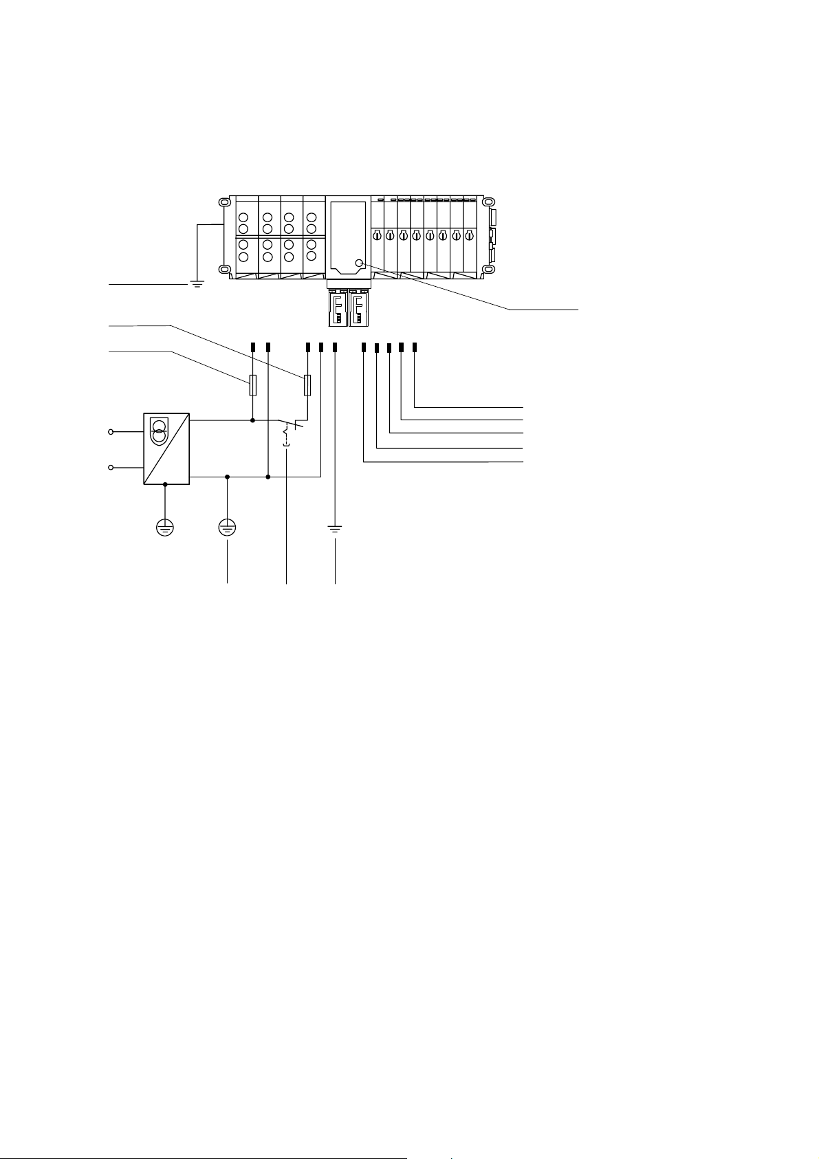
Example of connection
The diagram below shows as an example how to connect a
24 V power supply for pins 1 and 3. Please note that:
– the load voltage of the outputs/valves must be protected
with an external fuse maximum T10 A against short circuit/overload.
– the power supply for the electronics/inputs must be pro-
tected with an external fuse 3.15 A against short circuit/
overload (recommended).
– the power supply for the sensors is additionally protected
with the built-in fuse (2 A).
– the common tolerance of 24 V DC
¦ 10 % must be ob-
served.
– both connections for potential equalization are connected
and that equalizing currents are prevented.
– the load voltage at pin 3 (valves/electric outputs) can be
switched off separately.
3-18
Festo P.BE-VIFB21-03-EN en 0010a
3. Installation
2
5
12 3 5
4
24 V
AC
AC
DC
DC
0V
*)
PEPE
1
Fuse for inputs/sensors (2 A)
22
3
2 Potential equalization
3 Load voltage for outputs/valves can be
switched off separately
*)
0 V connected internally
4
123
54
to next
valve
terminal
4 External fuse (3.15 A) for electronics/
inputs
5 External fuses (10 A) for outputs/
valves
1
Fig. 3/8: Example – connecting a common 24 V supply and the potential equalization
Festo P.BE-VIFB21-03-EN en 0010a
3-19
3. Installation
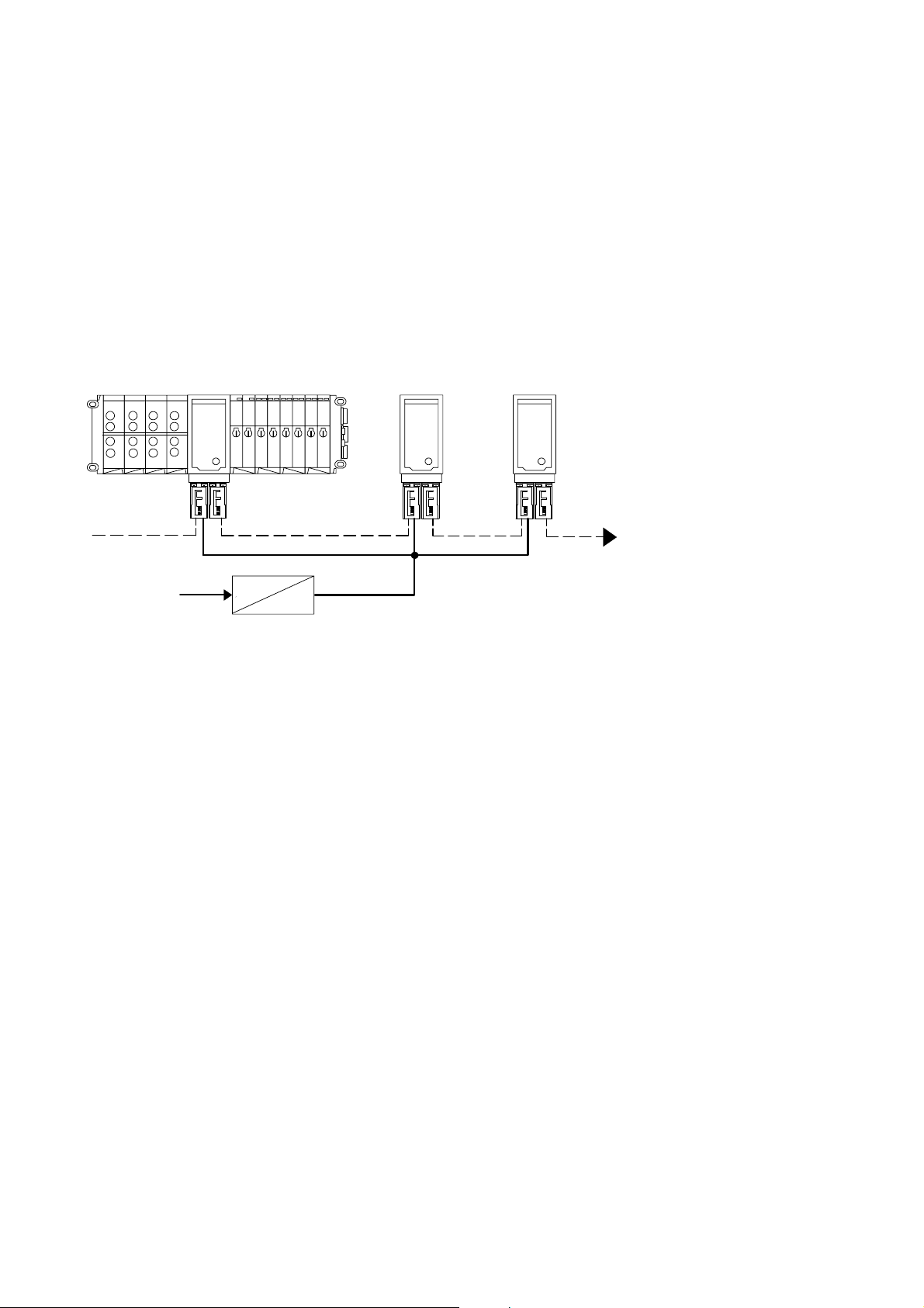
Power supply
You can arrange the power supply for several valve terminals
either:
– star-shaped or
– in series.
Connect the power supply star-shaped if you want short supply cables (this reduces voltag drop).
230 VAC
24 VDC
Fig. 3/9: Star-shaped 24 V power supply
3-20
Festo P.BE-VIFB21-03-EN en 0010a
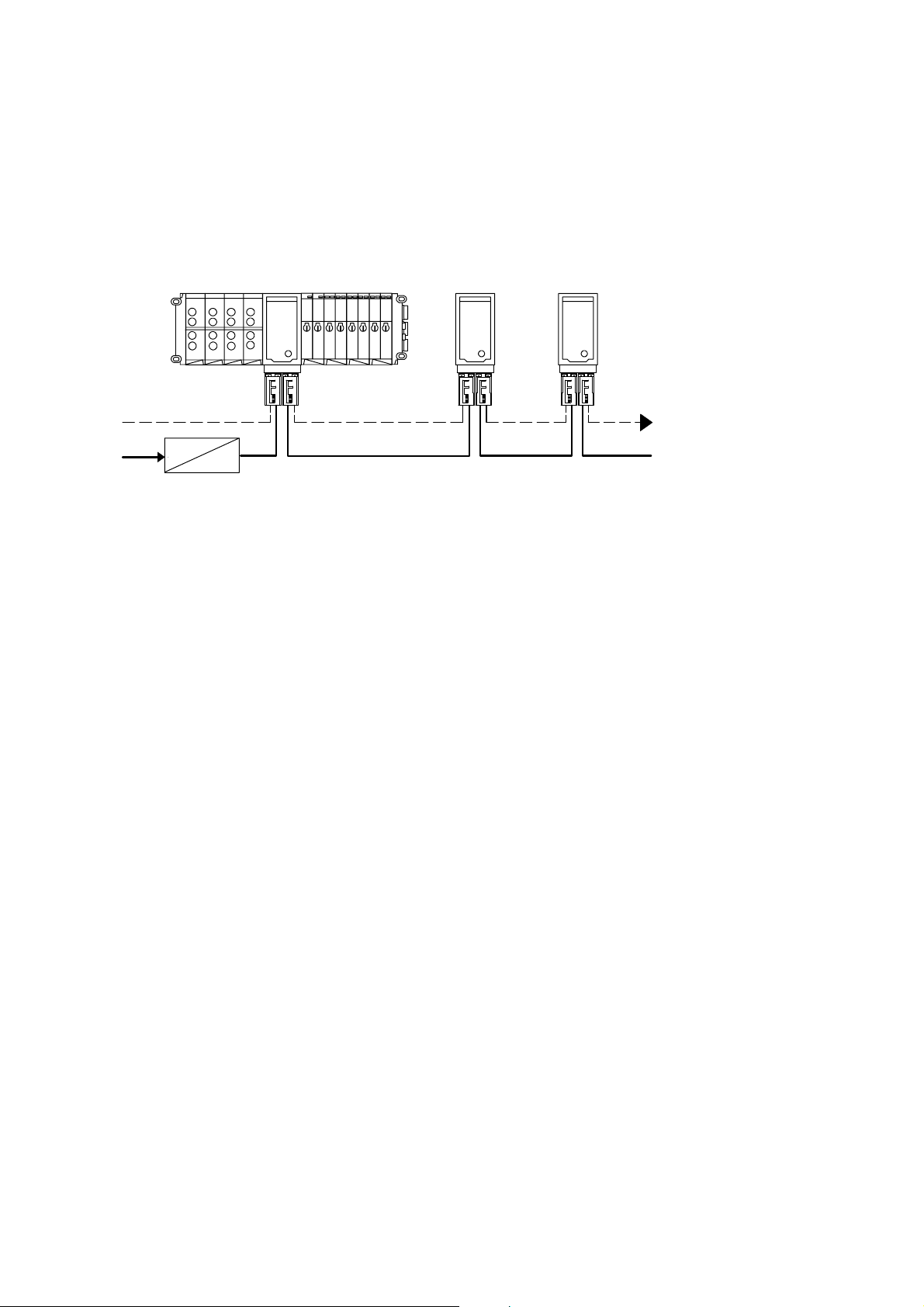
3. Installation
If you wish to connect the 24 V load voltage in series, note
that the sum current of the 24 V power supply must not exceed 16 A per contact of the power supply plug. If this value
is exceeded, a second 24 V power supply must be provided.
230 VAC
24 VDC
Fig. 3/10: Common 24 V power supply
Festo P.BE-VIFB21-03-EN en 0010a
3-21

3. Installation
3.4 INTERBUS interface
There are two connections on the node for connecting it to
the INTERBUS. One of these connections is for the incoming
cable; the other is for the continuing bus cable.
1 INTERBUS optical
fibre waveguide,
incoming
2 INTERBUS optical
fibre waveguide,
continuing
12
Fig. 3/11: Connecting the INTERBUS optical fibre waveguide interface
3-22
Festo P.BE-VIFB21-03-EN en 0010a

3. Installation
3.4.1 Conecting the optical fibre waveguide Rugged-Line plug
The method of connecting the optical fibre waveguide cable
to the optical fibre waveguide connection in the Rugged-Line
plug is described in Appendix B.2.
Please note
Connect the Rugged-Line plug only when the power supply
is switched off.
Proceed as follows:
1. Switch off the power supply.
2. Remove the existing protective cap.
3. Open the fuse clip and insert the Rugged-Line plug into
the interface of the incoming or continuing optical fibre
waveguide(seeFig.3/12).
Festo P.BE-VIFB21-03-EN en 0010a
4. Close the fuse clip.
3-23

3. Installation
2
1 Busorpower
supply connection, incoming
2 Busorpower
supply connection, continuing
1
Fig. 3/12: Bus or power supply connections
3-24
Please note
Unused connections must be sealed, see Appendix B
”Sealing unused connections in the Rugged-Line plug.”
Festo P.BE-VIFB21-03-EN en 0010a

Commissioning
Chapter 4
4-1Festo P.BE-VI FB21-03-E N en 0010a

4. Commissioning
Contents
4. Commissioning 4-1................................................
4.1 Configuring and addressing the valve terminal 4-3.......................
4.1.1 Ascertaining the configuration data 4-3................................
4.1.2 Calculating the number of inputs/outputs 4-5...........................
4.1.3 Address assignment of the valve terminal 4-6...........................
4.1.4 Address assignments after extension/conversion 4-12.....................
4.2 INTERBUS – Configuring and addressing the bus 4-14.....................
4.2.1 General commissioning instructions 4-14................................
4.2.2 Configuring the bus with CMD software 4-16.............................
4.2.3 Configuring the bus without CMD software 4-25..........................
4.2.4 Addressing the inputs and outputs 4-27.................................
4.2.5 Entering process data via the CMD software 4-30.........................
4.2.6 Status bits 4-34.....................................................
4.2.7 Other instructions 4-36...............................................
4-2
Festo P.BE-VIFB21-03-EN en 0010a

4. Commissioning
4.1 Configuring and addressing the valve terminal
4.1.1 Ascertaining the configuration data
Before configuring, you must ascertain the exact number of
inputs/outputs available. A multi-functional valve terminal
consists of a different number of I/Os, depending on what
you have ordered.
Please note
S A valve terminal with field bus node provides four status
bits for diagnosis. These bits are always assigned automatically within the terminal when there are input
modules.
S The s tatus bits must be treated like inputs and occupy
four input addresses.
S The maximum possible extent to which the valve ter-
minal can be equipped, is limited by the addressing limits of the field bus protocol and the mechanical limits
of the terminal.
Festo P.BE-VIFB21-03-EN en 0010a
4-3

4. Commissioning
The table below indicates the I/Os required per module for
configuration.
Modulart
MIDI/MAXI-manifold (type 03)
– single-solenoid manifold
– Double-solenoid manifold
4-output module (4 digital outputs)
4-input module ( 4 digital inputs)
8-input module ( 8 digital inputs)
16-input module (16 digital inputs)
Multi-I/O module
*) The I/Os are assigned automatically within the terminal,
irrespecitve of whether an input/output is actually used.
**) The status bits are assigned automatically within the terminal
as soon as there are input modules.
Anzahl belegter
*)
EAs
2 outputs4 outputs
4 outputs
4 inputs
8 inputs
16 inputs
12 inputs + 8 o utputs
4 inputs
Fig. 4/1: Number of assigned I/Os per module
4-4
Festo P.BE-VIFB21-03-EN en 0010a
4. Commissioning
4.1.2 Calculating the number of inputs/outputs
Copy this table for further calculations.
Eingänge
1. Number of 4-input module ________ · 4
2. Number of 8-input modules ________
3. Number of 16-input modules ________
4. Number of other inputs, e.g. multi-I/O module
5. .The 4 status bits are assigned internally automatically
by the terminal.
Total number of inputs to be configured
· 8
· 16
Outputs
6. Number of single manifolds ________ · 2
7. Number of double manifolds ________
Intermediate sum 6. + 7.
8. .Check whether the sum of 6. + 7.
Is divisible by four without remainder.
This check must be carried out because of the
4-bit orientated addressing of the terminal.
Case distinction:
a) If divisible by four without remainder, continue with 9.
b) If not divisible without remainder, round up to next half byte (+1...3).
· 4
+
+
+
+
=
+
=
+
S E
S E
S E
S E
4E
S E
S O
S O
S O
S 2O
9. Number of electric 4-output modules ________
10.Number of other outputs, e.g. multi-I/O module
Total number of outputs to be configured
Festo P.BE-VIFB21-03-EN en 0010a
· 4
+
+
=
S O
S O
S O
4-5

4. Commissioning
4.1.3 Address assignment of the valve terminal
The address assignment of the outputs of a multi-functional
valve terminal depends on the modules/valves fitted on the
terminal. A distinction must be made between the following
fitting variants:
– valves and digital I/O modules
– only valves
– only digital I/O modules
The basic rules described below apply to the address assignment of these fitting variants. A detailed example is given
after these basic rules.
Please note
If two addresses are assigned for one valve location, the
following assignment applies:
lower-value address > pilot solenoid 14
higher-value address > pilot solenoid 12
4-6
Festo P.BE-VIFB21-03-EN en 0010a

4. Commissioning
Basic rule for addressing
With mixed fitting, consideration is given to the address assignment of the valves, the digital I/O modules and the
status bits.
Outputs
1. The address assignment of the outputs does not depend
on the inputs.
2. Address assignment of the valves:
– Addresses are assigned in ascending order
without gaps
– Counting begins on the node from left to right.
– Maximum 26 valve solenoid coils can be addressed
– Single manifolds always occupy 2 addresses.
– Double manifolds always occupy 4 addresses.
3. Rounding up to 4 bits: case distinction:
a) If the number of valve addresses is divisible by 4
without remainder, continue with point 4.
b) If the number of valve addresses is not divisible by
4 without remainder, you must round the addresses
up to 4 because of the 4-bit orientated addressing.
The bit thus rounded up in the address range cannot
be used.
Festo P.BE-VIFB21-03-EN en 0010a
4. Address assignment of the outputs:
The digital outputs are addressed after the (rounded up
4-bit) addresses of the valves.
– Addresses are assigned in ascending order without
gaps.
– Counting begins on the node from right to left.
– Counting on the individual modules is from the top to
the bottom.
– Digital output modules occupy 4 or 8 addresses.
4-7

4. Commissioning
Inputs
1. The address assignment of the inputs does not depend
on the outputs.
2. Address assignment of the inputs:
– Addresses are assigned in ascending order without
gaps.
– Counting begins on the node from right to left.
– Counting on the individual modules is from the top to
the bottom.
– Input modules occupy 4, 8, 12 or 16 addresses.
3. Status bits:
The address assignment of the status bits depends on
the fitting variants of the inputs and on the configuration.
The following basic rule applies:
– The status bits are only available if input modules are
connected to the terminal and configured.
– Addressing:
The status bits are transferred to the four highestvalue positions in the configured address range.
4-8
Festo P.BE-VIFB21-03-EN en 0010a

4. Commissioning
1
When the power supply is switched on, the valve terminal
recognizes all available pneumatic modules and digital input/
output modules automatically and assigns the appropriate
addresses. If a valve location remains unused (blanking
plate) or if an input/output is not connected, the relevant
address will still be assigned. The diagram below shows an
example of address assignment.
2 3456
0
8
1
2
9
3
4
10
5
6
11
7
1 4-input module
2 8-input module
3 4-output module
20
16
21
17
22
18
23
19
0
12345678910111213
4 SINGLE manifold
5 DOUBLE manifold
6 Round up (not used)
Fig. 4/2: Address assignment of a terminal with digital I/Os
Remarks on the diagram:
– If single-solenoid valves are fitted onto double manifolds,
four addresses will be occupied for valve solenoid coils;
the higher address will in each case remain unused (see
address 3).
1514
Festo P.BE-VIFB21-03-EN en 0010a
4-9

4. Commissioning
– If unused valve locations are sealed with blanking plates,
the addresses will still be assigned (see addresses 12,
13).
– Due to the 4-bit orientated addressing of the modular
valve terminal, the last valve location will always be
rounded up to a full 4 bits (providing the fittings do not
already use the full four bits). Two addresses cannot,
therefore, always be used (see addresses 14, 15).
Additional instructions for valve terminal without I/O modules
If only valves are used, the address assignment will always
be as described in basic rule for addressing.
Please note
– Maximum 26 valve solenoid coils can be addressed.
– There is no rounding of the last two positions on the
valve side.
– Valve terminals without input modules do not require a
configuration for inputs. The status bits are not therefore available.
4-10
Festo P.BE-VIFB21-03-EN en 0010a

4. Commissioning
Additional instructions for valve terminal without valves
If only electric I/Os are used, the address assignment will
always be as described in basic rule for addressing.
Please note
– Counting begins immediately to the left of the node.
– There is no rounding of the last two positions on the
valve side.
– The maximum possible extent to which equipment can
be fitted on the valve terminal is limited by the addressing limits of the relevant field bus protocol and by the
mechanical limits of the valve terminal (92inputs or 48
outputs).
Festo P.BE-VIFB21-03-EN en 0010a
4-11

4. Commissioning
4.1.4 Address assignments after extension/conversion
A speciality of the multi-functional valve terminal is its flexibility. If the demands placed on the machine change, different equipment can be fitted onto the valve terminal.
Caution
If the terminal is extended or converted at a later date, the
input/output addresses may be shifted. This applies in the
following cases:
– When one or more pneumatic modules are added or
removed at a later date.
– When a pneumatic module with single-solenoid valves is
replaced by a new module with double-solenoid valves
or vice versa.
– When additional input/output modules are added be-
tween the node and exsting input/output modules.
– Existing input/output modules are removed or replaced
by input/output modules which occopy more fewer
input/output addresses.
4-12
If the configuration of the inputs is modified, the addresses
of the status bits will be shifted.
Festo P.BE-VIFB21-03-EN en 0010a

4. Commissioning
Using the standard fitting shown in the previous diagram, the
diagram below shows as an example the modifications which
can occur to the address assignment when extra equipment
is added to the valve terminal. Two double-solenoid manifolds and two single-solenoid manifolds have been added to
the valves. An 8-input module and a 4-output module have
been removed from the electric I/Os.
1 2 34 5 436
0
0
20
21
1
2
22
3
23
12345678910111213
1514171618
19
1 4-input module
2 4-output module
3 Single-solenoid manifold
4 Double-solenoid manifold
5 Power supply
6 No rounding
Fig. 4/3: Address assignment of a terminal with digital IOs after extension/conversion
Please note:
Pressure supply modules and intermediate pressure supply
modules do not occupy any addresses.
Festo P.BE-VIFB21-03-EN en 0010a
4-13

4. Commissioning
4.2 INTERBUS – Configuring and addressing the bus
4.2.1 General commissioning instructions
Before commissioning or programming you must compile a
configuration list of all the connected field bus slaves. On the
basis of this list you can:
– carry out a comparison between the nominal and the
actual configurations in order to detect any connection
faults;
– access these specifications during the syntax check of a
program in order to avoid addressing faults.
Configuration of the valve terminal requires an exact procedure, as different configuration specifications are sometimes required for each terminal due to the modular structure. Please read carefully the information contained in the
sections which follow.
4-14
Festo P.BE-VIFB21-03-EN en 0010a

4. Commissioning
Switching on the power supplies
Please note
Observe here also the instructions in the manual
for your controller.
When the controller is switched on, it automatically carries
out a comparison bewteen the nominal and the actual configurations. For this configuration comparison it is important
that:
– the specifications on the configuration are complete and
correct;
– the field bus slaves are supplied with power, in order that
they can be recognized when the ACTUAL configuration is
ascertained.
Switch on the power supply for all the slaves simultaneously
if there is a central switch or, switch the power supplies on in
the following sequence:
Festo P.BE-VIFB21-03-EN en 0010a
1. first the power supply for the field bus slaves,
2. then the power supply for the controller.
4-15

4. Commissioning
4.2.2 Configuring the bus with CMD software
This chapter describes as an example the main steps required in the CMD software, before you can insert a Festo
valve terminal into your project. A general and comprehensive description can be found in the relevant manual for the
CMD software. In the following, it is assumed that the user is
familiar with the information contained in the CMD manual.
Please note
The software packages are subject to modifications which
are not taken into consideration in this manual.
The examples used here for the screen displays have been
taken from CMD software version 4.
Further and current information can be found in the manual for your CMD software.
4-16
Festo P.BE-VIFB21-03-EN en 0010a

4. Commissioning
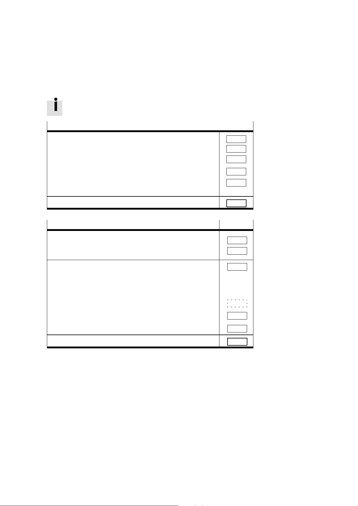
Inserting with the Ident code
Proceed as follows:
S Open the dialogue window of the INTERBUS module.
S Select the option ”Insert with Ident code... .”
Fig. 4/4: Inserting bus slaves with Ident code
Festo P.BE-VIFB21-03-EN en 0010a
4-17

4. Commissioning
The following dialogue window will then appear:
Fig. 4/5: Dialogue window ”Insert slave”
Enter the following in the dialogue fields:
4-18
S Ident code:
Enter the appropriate Ident code according to the table.
Valve terminal equipment
Only outputs
Only inputs 2
Inputs and outputs
1
Valve coils and/or electric outputs
1
1
Ident-Code
1
3
S Process data channel:
Enter here the number of inputs and/or outputs on your
valve terminal. Note the following:
Festo P.BE-VIFB21-03-EN en 0010a
4. Commissioning
Please note
– The number of inputs and/or outputs must be rounded
up to the next word limit.
– If the number of input bits differs from the number of
output bits, the larger number is decisive in each case
for entering the process data channel bits.
– The status bits of a valve terminal with inputs occupy
four additional inputs.
The table below gives a summary of the possible number of
bits for the process data channel.
Valve terminal equipment
Up to 12 + 4 inputs 16
Up to 28 + 4 inputs 32
Up to 44 + 4 inputs 48
Up to 60 + 4 inputs 64
Up to 76 + 4 inputs 80
Up to 92 + 4 inputs 96
Up to 16 outputs
Up to 32 outputs
Up to 48 outputs
Up to 64 outputs
Up to 80 outputs
1
Valve coils and/or electric outputs
1
1
1
1
1
Process data channel bits
S Slave type:
The default entry ”Remote bus slave” can be used.
S Save these entries with OK.
16
32
48
64
80
Festo P.BE-VIFB21-03-EN en 0010a
4-19

4. Commissioning
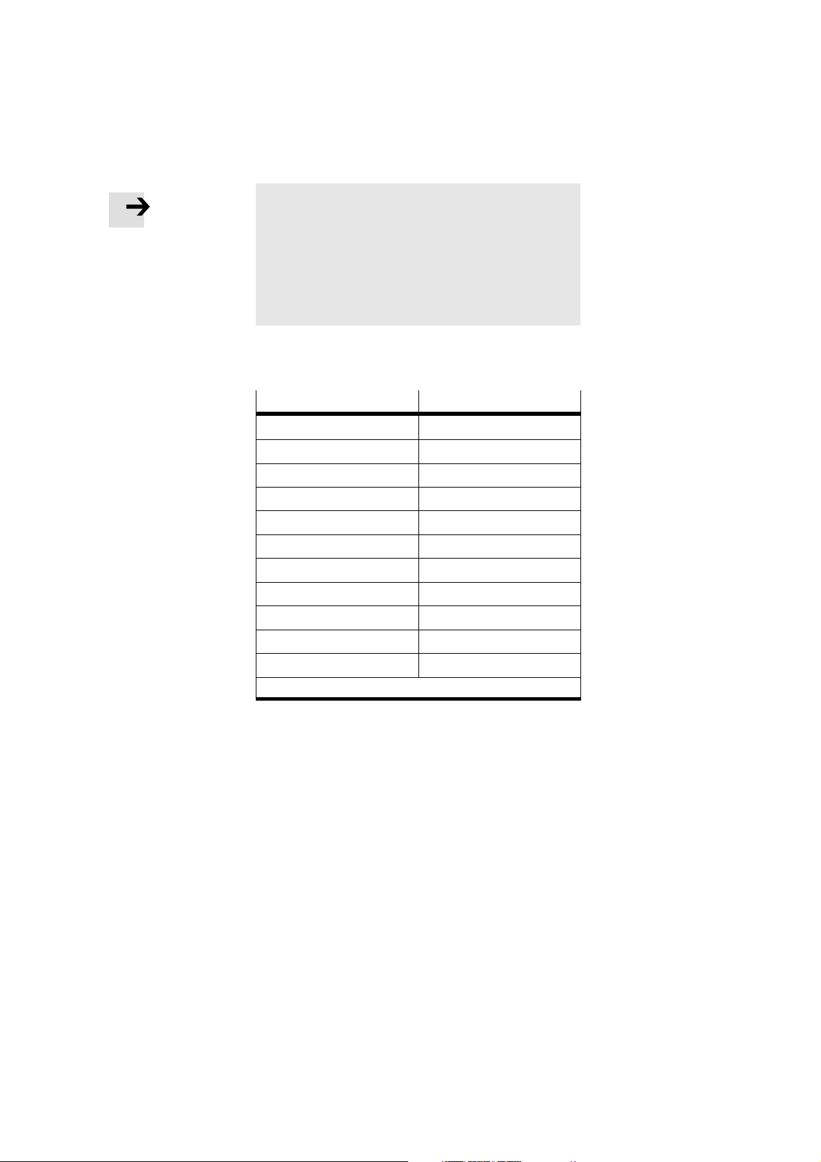
Insert slave description
In the following dialogue window you can describe the slave
and enter specific information on the valve terminal, e.g. station name and slave image.
4-20
Fig. 4/6: Dialogue window ”Insert slave description”
Festo P.BE-VIFB21-03-EN en 0010a

4. Commissioning
Possible entries:
– Profile number:
The Festo valve terminal conforms to the INTERBUS I/O
profile 12. Enter this value in the field ”Profile number.”
– Interface type:
The default entry ”Universal interface type” can be used.
Alternately, you can select the type ”Remote bus.”
– Picture:
Open the dialogue window ”Picture ...” if you wish to use
specific icons for the Festo valve terminal.
The specific icons of the Festo valve terminals can be found
on the accompanying CD ROM.
S If If necessary, read the file ”Readme.txt” on on the CD
ROM for a quick summary of the contents of the CD ROM.
Festo P.BE-VIFB21-03-EN en 0010a
S Copy the file ”Festo.ICL” into the CM D directory
Directory \PICTURE\.
4-21
4. Commissioning
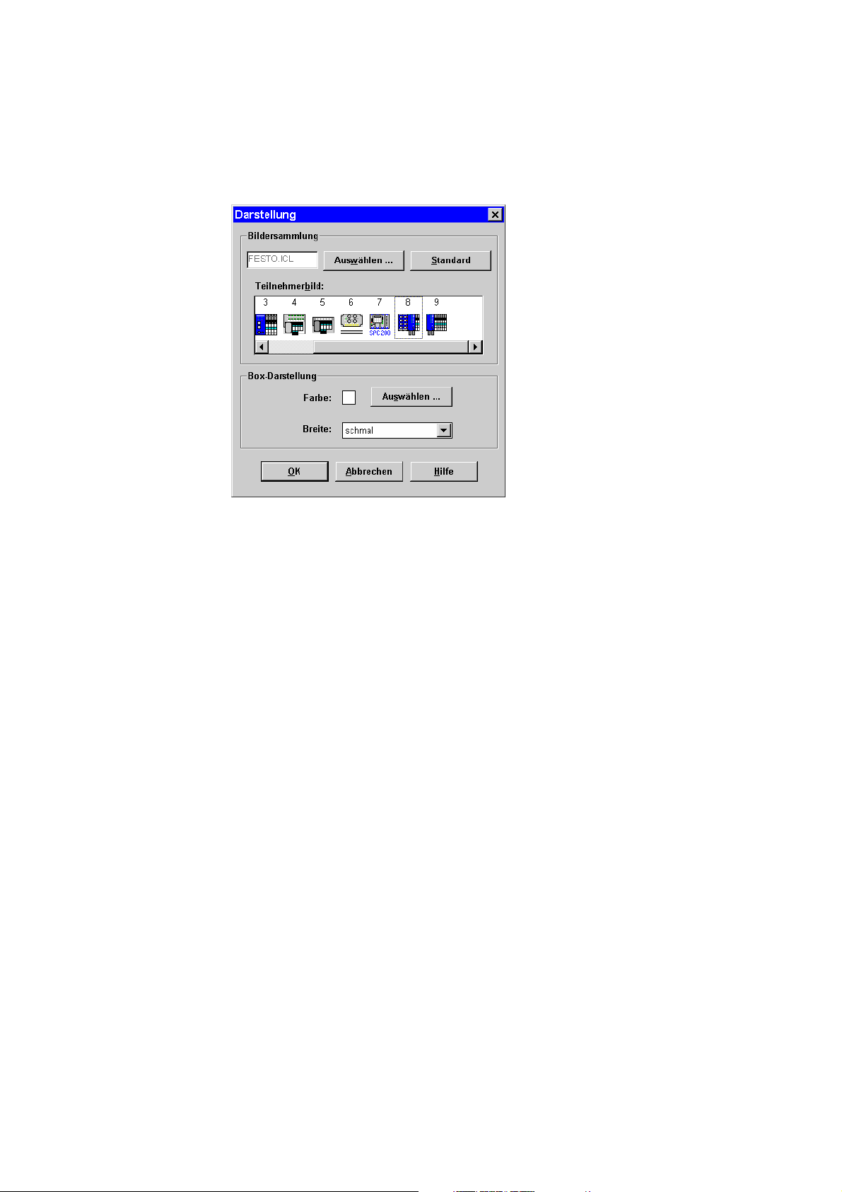
The following dialogue window will then appear:
4-22
Fig. 4/7: Dialogue window ”Slave picture” for selecting an
icon
S Use the button ”Select ...” to select the file Festo.ICL.
S Mark icon which corresponds to your valve terminal (no. 8
or no. 9 in Fig. 4/7).
S Save the icon with OK.
Festo P.BE-VIFB21-03-EN en 0010a

4. Commissioning
The icons are numbered. The following table shows the relationship between the number of the icon and the valve terminal type.
Icon no.
3 Types 03-05 only with valves
4 Type 02 with inputs and outputs
5 Type 02 only with valves
6 Type 10 with INTERBUS-Loop
7 SPC200 positioning system
8 Type 03 with inputs and outputs,
9 Type 03 only with outputs,
Valve terminal type
INTERBUS optical fibre waveguide Rugged-Line
INTERBUS optical fibre waveguide Rugged-Line
Festo P.BE-VIFB21-03-EN en 0010a
4-23

4. Commissioning
When all the entries have been made, the valve terminal is
inserted into your bus structure as follows (example):
Fig. 4/8: Example of valve terminal inserted into bus structure
4-24
Festo P.BE-VIFB21-03-EN en 0010a

4. Commissioning
4.2.3 Configuring the bus without CMD software
Logical addressing
Please note
S ID CODE
Configure a valve terminal as follows:
– terminal only with outputs
– terminal only with inputs with Ident code 2
– terminal with inputs and outputs with Ident code 3
S Process data channel
The number of inputs and/or outputs must be rounded
up to the next word limit.
If the number of input bits differs from the number of
output bits, the larger number is always decisive for
entering the process data channel bits.
S The s tatus bits of a valve terminal with inputs occupy
four additional inputs.
1)
with Ident code 1
Festo P.BE-VIFB21-03-EN en 0010a
1)
Valve coils and/or electric outputs
4-25

4. Commissioning
These specifications must be known by or ascertained for
each bus slave. Proceed as follows with the valve terminals:
Ascertain the number of I/Os per valve terminal (see chapter
4.1.2, section ”Ascertaining the number of I/Os”).
S Take into consideration the four status bits in the case of
valve terminals with inputs.
S Ascertain the Ident code and the number of bits in the
process data channel according to the table below.
S Assign logical IN and OUT addresses to each slave.
Valve terminal
equipment
Inputs
max
0
0
0
0
0
12+4
28+4
44+4
60+4
76+4
92+4
12+4
28+4
44+4
60+4
76+4
92+4
Outputs
max.
16
32
48
64
74
0
0
0
0
0
0
16
32
48
64
80
96
IDCode
1
1
1
1
1
2
2
2
2
2
2
3
3
3
3
3
3
Process
data channel bits
16
32
48
64
80
16
32
48
64
80
96
16
32
48
64
80
96
Meaning
Up to
16 outputs
32 outputs
48 outputs
64 outputs
80 outputs
Up to
12 inputs + 4 status bits
28 inputs + 4 status bits
44 inputs + 4 status bits
60 inputs + 4 status bits
76 inputs + 4 status bits
92 inputs + 4 status bits
16 outputs and up 12 inputs + 4 status bits
32 outputs and up 28 inputs + 4 status bits
64 outputs and up 44 inputs + 4 status bits
64 outputs and up 60 inputs + 4 status bits
80 outputs and up 74 inputs + 4 status bits
92 outputs and up 92 inputs + 4 status bits
4-26
Festo P.BE-VIFB21-03-EN en 0010a

4. Commissioning
4.2.4 Addressing the inputs and outputs
Further information on addressing can be found in the manuals for your controller and the INTERBUS module.
The address assignment (process data assignment) of the
inputs and outputs of a valve terminal on the INTERBUS or a
compatible system depends primarily on the INTERBUS module and on the control system used.
Caution
There are different address assignments on the INTERBUS.
The reason for this is the assignment of the process data
within the INTERBUS module and not within the Festo
valve terminal.
S When assigning the addresses, note the position of the
high and low bytes, because in conjunction with some
control systems the position of these bytes can be
swapped.
Festo P.BE-VIFB21-03-EN en 0010a
In this way you will avoid faults when addressing the inputs/
outputs.
4-27

4. Commissioning
The following examples explain the different address assignments and the position of the low bytes (n) and the high
bytes (n+1). A distinction is made between the:
– Siemens mode and the
– standard mode.
Example:
– In Siemens mode, the lower-value output byte (byte n) is
mapped on valve coils 0 - 7 of the valve terminal; byte
n+1 on the next coils (8 -15) etc.
– In standard mode, the lower-value output byte (byte n) is
mapped on valve coils 8 -15 of the valve terminal; byte
n+1 on valve coils 0 -7.
In the chapter after the following examples, you will find instructions on addressing with the CMD software (process
data assignment) and on modifying the position of the low
and high bytes (”Byte swap”).
4-28
Festo P.BE-VIFB21-03-EN en 0010a

4. Commissioning
Example: address assignment of the outputs
1
2
Standard mode 2 Siemens mode
1
Fig. 4/9: Address assignment of the outputs with Siemens controllers and other con-
trollers on the INTERBUS
Please note
If two addresses are assigned for one valve location, the
following assignment applies:
– lower-value address: pilot solenoid 14
– higher-value address : pilot solenoid 12
Festo P.BE-VIFB21-03-EN en 0010a
4-29

4. Commissioning
1
Standard mode
Example: address assignment of the inputs
2 Siemens mode
1
3 8-input module
4 4-input module
2
34
Fig. 4/10: Address assignment of the inputs with Siemens controllers and other con-
trollers on the INTERBUS
4.2.5 Entering process data via the CMD software
The CMD software offers, as from version 4, the possibility of
assigning each input/output of a valve terminal within the
configured address range to any input/output in the PLC/IPC.
To do this, proceed as follows:
S Add a valve terminal to your bus structure (necessary
steps see section 4.2.2 ”Configuring the bus with CMD
software”).
4-30
Festo P.BE-VIFB21-03-EN en 0010a

4. Commissioning
S Use the right-hand mouse button to open the dialogue
window of the inserted valve terminal.
S Select the option ”Process data.”
Fig. 4/11: Selecting the option for entering the process data
Festo P.BE-VIFB21-03-EN en 0010a
4-31

4. Commissioning
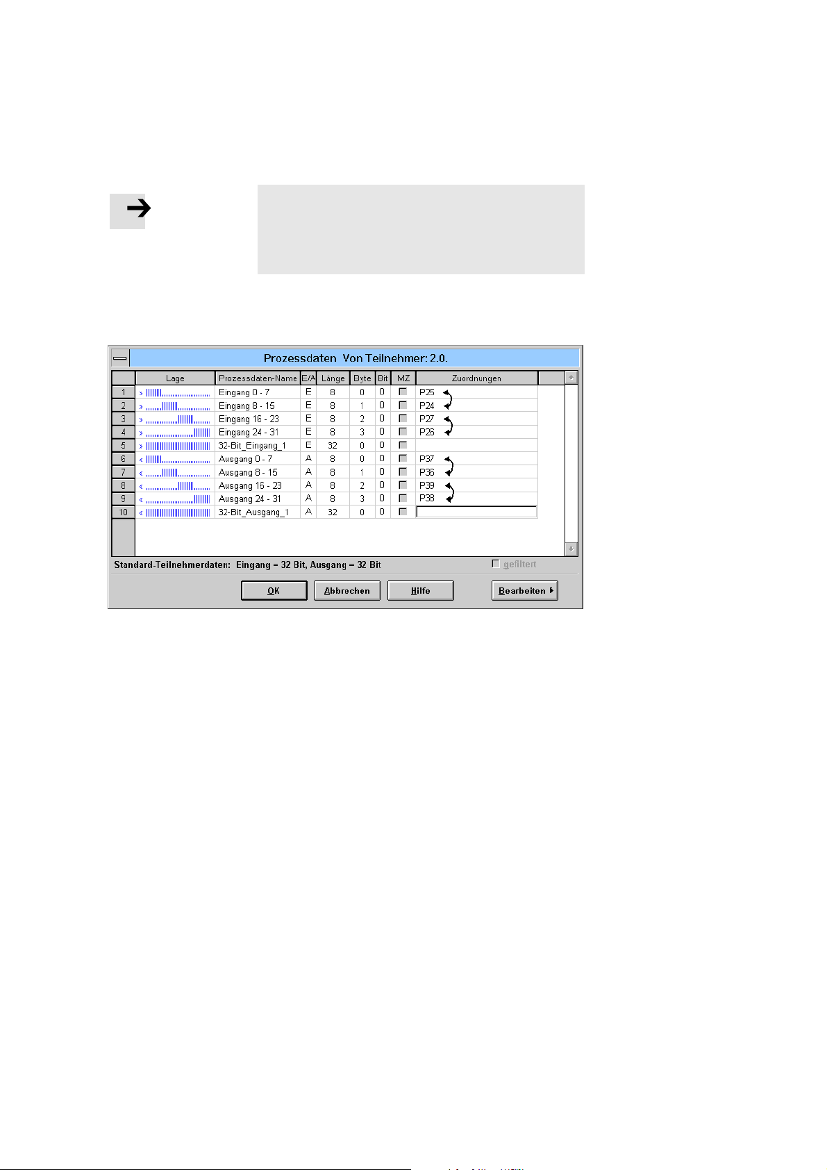
In the following dialogue window you can determine the I/O
addresses. In this way you can adapt the I/Os of your valve
terminal to the PLC used. If necessary, swap the high byte
and low byte (byte swap). The following mapping shows the
byte-by-byte assignment for a Siemens S5.
Fig. 4/12: Entering process data ? Example for ”Siemens mode”
4-32
Festo P.BE-VIFB21-03-EN en 0010a
4. Commissioning
Please note
In order to correct the byte swap, it will suffice if you assign the appropriate I/O address to each byte.
An individual I/O assignment at bit level is only necessary
in very few cases.
The following dialogue window shows you the entries which
are necessary for swapping the assignment of the high byte
and the low byte (example: byte swap for ”standard mode”).
Fig. 4/13: Modifying the I/O assignment ? Example for ”standard mode”
Festo P.BE-VIFB21-03-EN en 0010a
4-33

4. Commissioning
4.2.6 Status bits
The status bits of a valve terminal serve for displaying internal valve terminal faults, e.g.:
– voltage below tolerance
– voltage switched off
– short circuit or overload
These error messages are treated like inputs and transmitted
with the rest of the inputs of a valve terminal to the INTERBUS master. There they can be interrogated, linked and processed as ”normal” inputs.
Further information on the function of the status bits can be
found in the secton ”Diagnosis via the INTERBUS” in chapter
5.3.
The status bits always occupy four addresses of the configured address range. If the inputs of the input addresses
thereunder are not used, the valve terminal will set them to
”logical zero.” The addresses of the status bits in the address
range of a valve terminal depend, like all inputs/outputs, on
the INTERBUS modue and on the control system used.
4-34
Festo P.BE-VIFB21-03-EN en 0010a

4. Commissioning
The following tables indicate the different positions of the
four status bits.
Valve terminal equipment
Ident code Process data chan-
Available address Addresses of the
range status bits
nel
1 No address range for
2or3
2or3
2or3
2or3
2or3
2or3
16
32
48
64
80
96
inputs
0 ... 15
0 ... 31
0 ... 47
0 ... 63
0 ... 79
0 ... 95
Fig. 4/14: Position of the status bits in ”Siemens mode”
Valve terminal equipment
Ident-Code Process data chan-
Available address Addresses of the
range status bits
nel
1 No address range for
2oder3
2oder3
2oder3
2oder3
2oder3
2oder3
16
32
48
64
80
96
inputs
0 ... 15
0 ... 31
0 ... 47
0 ... 63
0 ... 79
0 ... 95
No status bits available
12, 13, 14, 15
28, 29, 30, 31
44, 45, 46, 47
60, 61, 62, 63
76, 77, 78, 79
92, 93, 94, 95
No status bits available
4, 5, 6, 7
20, 21, 22, 23
36, 37, 38, 39
52, 53, 54, 55
68, 69, 70, 71
84, 85, 86, 87
Fig. 4/15: Position of the status bits in ”Standard mode”
Festo P.BE-VIFB21-03-EN en 0010a
4-35

4. Commissioning
4.2.7 Other instructions
Preprocessing
Under preprocessing on the INTERBUS, we understand the
logical linking of process data within the INTERBUS module.
Please note
All inputs/outputs of a module can be preprocessed (see
manual for CMD software from Phoenix Contact).
Periphery faults (PF)
If a fault is detected by the valve terminal and entered in the
statusbits,aaperipheryfaultwillalsobetriggered and
transmitted to the INTERBUS module, where it will be displayed.
The reasons for periphery faults can be:
4-36
1. The voltage of the valves and electric outputs is below
the tolerance (21.6 V).
2. The voltage for the valves and electric outputs is switched
off (e.g. EMERGERNCY STOP).
3. The power supply for the inputs/sensors is switched off
(e.g. internal fuse triggered).
4. There is a short circuit or overload at the digital outputs.
Festo P.BE-VIFB21-03-EN en 0010a

4. Commissioning
Masking out an error message (up till INTERBUS
G3 module)
When delivered from the factory, the periphery fault of a valve
terminal can be triggered by all four causes (summary of periphery faults see chapter 5.3 ”Diagnosis via INTERBUS”).
However, the fault can be partially suppressed if DIL switch 2
inside the node is switched on (compare the section ”Setting
the DIL switch elements” in chapter 3.2.2):
– DILswitchelement2toON:
error causes 1 and 2. (tolerance of valve/output voltage
and EMERGENCY STOP) are not transmitted, but suppressed. Only causes 3 and 4 are transmitted.
Please note
Error causes 1 and 2 a re entered in the status bits irrespective of the setting of DIL switch 2.
Festo P.BE-VIFB21-03-EN en 0010a
– DILswitchelement2toOFF(factorysetting):
All error causes will be transmitted as periphery faults to
the INTERBUS.
The system is not stopped by periphery faults. You can determine the reaction to periphery faults by parametrizing the
INTERBUS module. You can also quit the periphery fault by
parametrizing the INTERBUS module.
4-37

4. Commissioning
Masking out an error message (as from INTERBUS
G4 module)
As from the INTERBUS G4 module, error messages can be
displayed or masked out by means of the CM D software
(SRC services) (summary of the periphery faults see the section ”Diagnosis via INTERBUS” in chapter 5.3).
Proceed as follows:
1. Open the dialogue window ”Activity/service editor” in the
CMD software
2. Select the entry ”Set valve request” in the list field
”Name.”
3. Enter the appropriate code in the 4-th field in the table.
Code 046C: error message US2 1 is masked out
Code 047C: All errors are shown
Code 0404: No error is shown
Code 0004: G4-compatible mode
4-38
Please note
The setting applies to the complete bus with all bus slaves.
Festo P.BE-VIFB21-03-EN en 0010a

Diagnosis and error treatment
Chapter 5
5-1Fest o P.BE-VIF B21-03-E N en 0010a

5. Diagnosis and error treatment
Contents
5. Diagnosis and error treatment 5-1....................................
5.1 Summary of diagnostic possibilities 5-3................................
5.2 On-the-spot diagnosis 5-4...........................................
5.2.1 Bus node 5-4......................................................
5.2.2 LED modules 5-6...................................................
5.2.3 On-the-spot error treatment 5-9......................................
5.2.4 Status bits 5-10.....................................................
5.3 Diagnosis via INTER BUS 5-13.........................................
5.3.1 Reaction to faults in the control system 5-17.............................
5-2
Fest o P.BE-VIF B21-03-E N en 0010a

5. Diagnosis and error treatment
5.1 Summary of diagnostic possibilities
The modular valve terminal offers extensive and user-friendly
possibilities of diagnosis and error treatment. The following
possibilities are available, depending on the equipment fitted
on the valve terminal:
Valve terminal with inputs
Valve terminal without inputs
Diagnostic
possibilities
Brief description
Advantage Fast access to error mess-
Status bits
Bit 26Bit 2
0
0
1
1
X
5
4
Bit 2
0
0
1
X
0
X
1
X
X
X
7
Bit 2
0
X
X
X
1
X = nicht relevant
The four status bits are
transmitted to the module as ”inputs” cyclically
with the normal inputs
ages, irrespective
LEDs
IN
OUT
UB
The LEDs show directly
configuration faults, hardware faults, bus faults,
etc.
Fast ”on-the-spot” error
recognition
of the module and the
master
Detailed des-
Chapter 5.3 Chapter 5.2 Chapter 5.3
cription
Fig. 5/1: Possibilities of diagnosis and error treatment
IB DIAG
RC
RD
F01
F02
US1
US2
IN
OUT
UB
Diagnostic status register
7
65432107654321
The valve terminal sets
the bit ”PF” in the diagnostic status register of
the module
Detailed error recognition, e.g. periphery faults
0
Festo P.BE-VIFB21-03-EN en 0010a
5-3
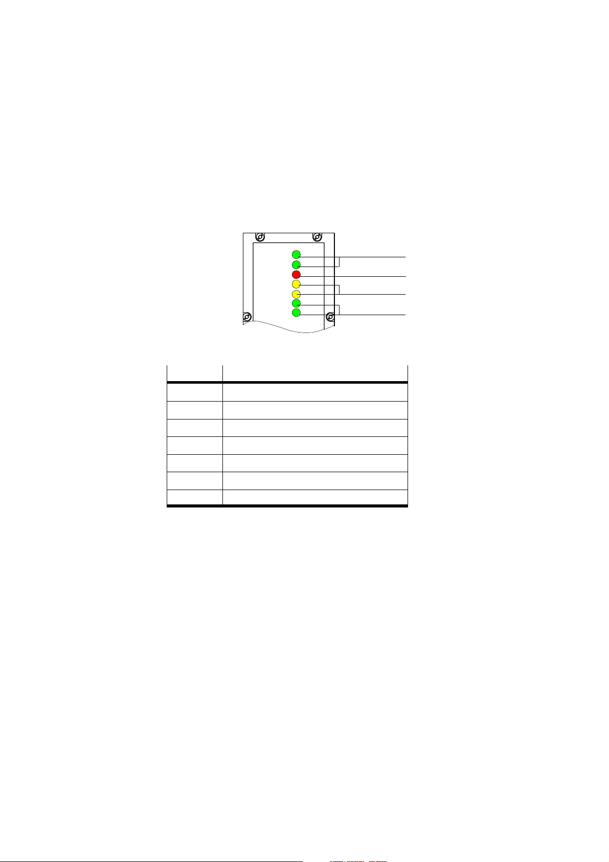
5. Diagnosis and error treatment
123
1
5.2 On-the-spot diagnosis
5.2.1 Bus node
The LEDs on the cover of the node indicate the operating
status of the valve terminal.
1 Green LED
operating status
display
2 Red LED
3 Yellow LED
Fig. 5/2: LEDs on the field bus node
IB DIAG
RC
RD
F01
F02
US1
US2
5-4
LED
IB DIAG INTERBUS diagnosis
RC Remote bus check
RD Remote bus disable
FO1 Diagnosis incoming optical fibre waveguide path
FO2 Diagnosis continuing optical fibre waveguide path
US1 Diagnosis logic voltage (electronics/sensors)
US2 Diagnosis load voltage (outputs/valves)
Meaning
Festo P.BE-VIFB21-03-EN en 0010a
 Loading...