

Festo HSW-x-AP Series, HSW-x-AS Series, HSW-10-AS, HSW-12-AS, HSW-16-AS Operating Instructions Manual
...
Handlingmodul
Handling module
HSW−...−AP/AS
(de) Bedienungs−
anleitung
(en) Operating
instructions
(es) Instrucciones
de utilización
(fr) Notice
d’utilisation
(it) Istruzione
per l’uso
(sv) Bruksanvisning
742 514
0812b

HSW−...−AP/AS
Esbedeuten/Symbols/Símbolos/
Symboles/Simboli/Teckenförklaring:
Warnung
Warning, Caution
Atención
Avertissement
Avvertenza
Varning
Hinweis
Please note
Por favor, observar
Note
Nota
Notera
Umwelt
Antipollution
Reciclaje
Recyclage
Riciclaggio
Återvinning
Zubehör
Accessories
Accesorios
Accessoires
Accessori
Tillbehör
Einbau und Inbetriebnahme nur von qualifi
ziertem Fachpersonal, gemäß Bedienungs
anleitung.
Fitting and commissioning to be carried out
by qualified personnel only in accordance
with the operating instructions.
El montaje y la puesta en funcionamiento,
debe ser realizado exclusivamente por
personal cualificado y siguiendo las
instrucciones de utilización.
Montage et mise
en service uniquement par
du personnel agréé, conformément aux
instructions d’utilisation.
Montaggio e messa in funzione devono
essere effettuati da personale specializzato
ed autorizzato in confomità alle istruzioni
per l’uso.
Montering och idrifttagning får endast
utföras av auktoriserad fackkunnig personal
i enlighet med denna bruksanvisning.
Deutsch 3 . . . . . . . . .
. . . . . . . . . . . . . . . . . . . . . . . . . . . . . . . . . . . . . . . . . . . . . . . . . . . . . . . . . .
English 33 . . . . . . . . . . . . . . . . . . . . . . . . . . . . . . . . . . . . . . . . . .
Español 63 . . . . . . . . . . . . . . . . . . . . . . .
Français 93 . . . . .
. . . . . . . . . . . . . . . . . . . . . . . . . . . . . . . . . . . . . . . . . . . . . . . . . . . . . . . . . . . . . .
Italiano 123. . . . . . . . . . . . . . . . . . . . . . . . . . . . . . . . . . . . . .
Svenska 153. . . . . . . . . . . . . . . . . . .
2
. . . . . . . . . . . . . . . . . . . . . . . . . . . . . . . . . . . . . . . . . . . .
. . . . . . . . . . . . . . . . . . . . . . . . . . . . . .
. . . . . . . . . . . . . . . . . . . . . . . . . . . . . . . . . . . . . . . . . . . . . . . .
. . . . . . . . . . . . . . . . . . . . . . . . . .
Festo HSW−...−AP/AS 0812b

HSW−...−AP/AS
Handlingmodul Typ HSW−...−AP/ASDeutsch
Inhaltsverzeichnis
1 Bedienteile und Anschlüsse 4 . . . . . . . . . . . . . . . . . . . . . . . . . . . . . . . . . . . .
2 Produktübersicht 5 . . . . . . . . . . .
3 Funktion und Anwendung 7 . . . . . . . . . . . . .
4 Transport und Lagerung 7 . . . . . . . . . . . . . . . . . . . . . . .
5 Voraussetzungen für den Produkteinsatz 8 . . . . . . . . . . . . . . . . . . . . . . . . .
6 Einbau 9 . . . .
Einbau
Einbau der Nutzlast 11 . .
Einbau statisches Justieren der Endlagen 13 . . .
Einbau pneumatisch 15 . . . . . . . . . . . . . . . . . . . . . . . . . .
Einbau elektrisch 16 . . . . . . . . . . . . . . . . . . . . . . . . . . . . . . . .
7 Inbetriebnahme 17 . . . . . . . . . . . . . . . . . . . . . . . . . . . . . . . . . . .
Inbetriebnahme Gesamtanlage 17 . . . . . . . . . . . . . . . . . . . . . . . . . . . . . . . . . .
Inbetriebnahme Probelauf 19 . .
8 Bedienung und Betrieb 22 . . . . . . . . . . .
9 Wartung und Pflege 24 . . . . . . . . . . . . . . . . . . .
10 Ausbau und Reparatur 25 . . . . . . . . . . . . . . . . . . . . . . .
11 Zubehör und Kombinationen 27 . . . . . . . . . . . . . . . . . . . . . . . . . . . . . .
12 Störungsbeseitigung 28 . . . . . . . . . . . . . . . . . . . . . . . . . . . . . . . . . . . . . . . . . .
. . . . . . . . . . . . . . . . . . . . . . . . . . . . . . . . . . . . . . . . . . . . . . . . . .
mechanisch 10 . . . . . . . . . . . . . . . . . . . . . . . . . . . . . . . . . . . . . . . . . . . .
. . . . . . . . . . . . . . . . . . . . . . . . . . . . . . . . . . . . . . . . . .
. . . . . . . . . . . . . . . . . . . . . . . . . . . . . . . . . .
. . . . . . . . . . . . . . . . . . . . . . . . .
. . . . . . . . . . . . . . . .
. . . . . . . . . . . . . . . . . . . . . .
. . . . . . . . . . . . . . . . .
. . . . . . . . . . . . . .
. . . . . . . . . . .
. . . . . . . . . . . . . . . . . . . . . . . . . . . . . . . . . . . .
. . . . . . . . . . . . . . . . . . . . . . . . . . . . .
. . . . . . . . . . . . . . . . . . . . . . . .
. . . . . . . . . . . . . . . . . .
. . . . .
13 Technische Daten 29
14 Kennlinien 31 . . . . .
Festo HSW−...−AP/AS 0812b Deutsch
. . . . . . . . . . . . . . . . . . . . . . . . . . . . . . . . . . . . . . . . . . . . .
. . . . . . . . . . . . . . . . . . . . . . . . . . . . . . . . . . . . . . . . . . . . . .
3

HSW−...−AP/AS
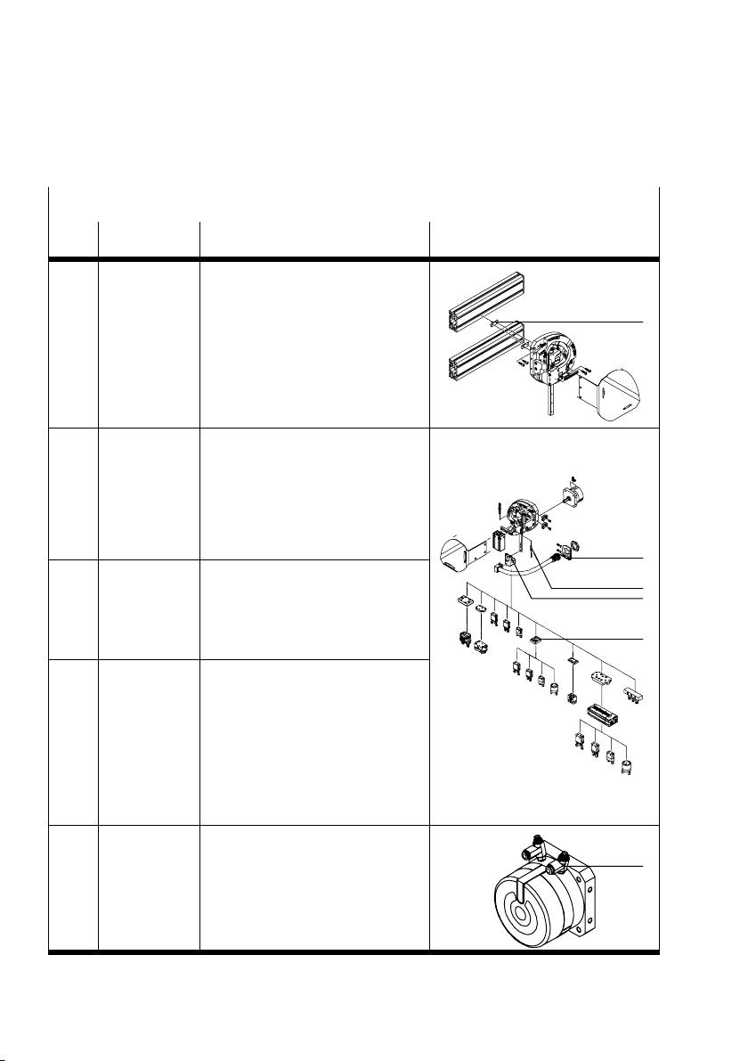
1Bedienteile und Anschlüsse
1
2
3
4
5
1 Anschlagelement zur Hubeinstellung:
Hydraulischer Stoßdämpfer/Fest−
anschlag bei HSW−10−...−AP/−AS
Anschlagschraube bei
HSW−12/16−...−AP
2 Schwenkhebel
6 Linearführung (Führungswagen)
7 Drehlager
8 Feder−Druckstück
9 End−Anschlag:
3 Kulisse mit Bahnführung
4 Verstellschraube zur Winkeleinstellung
aJ Grundplatte mit Durchgangs−Bohrungen und
5 Nut für Näherungsschalter SMx−8
Bild1: Bedienteile und Anschlüsse HSW (Vorderansicht)
aJ
9
8
7
6
Anschlagbolzen bei HSW−10
Hydraulischer Stoßdämpfer/Festanschlag
bei HSW−12/16−...−AP/−AS
Zentriersenkung für Befestigungsschrauben
4
Festo HSW−...−AP/AS 0812b Deutsch

HSW−...−AP/AS
füh
6
2 Produktübersicht
Grundausführung Varianten
HSW−10, HSW−12, HSW−16
Das Handlingmodul wird standardmäßig in den
Baugrößen 10, 12, 16 mit folgenden Funktions
elementen fertig montiert geliefert:
Grundplatte mit variablen Montage− und
Befestigungsmöglichkeiten aJ
2 verstellbare Führungskulissen zur
Bahnsteuerung über Wälzlagerführung 3
1 Linear
1 Drehlager
2 Anschläge in den Endlagen mit jeweils
einem Stoßdämpfer (bei HSW−...−AP) bzw.
Gummipuffer (bei HSW−...−AS) 1/9 und
einer Befestigungsschiene für Näherungs
schalter 5
rung
Optionen
HSW−...−SD
Handlingmodul mit Schutzdeckel. Die Ausfüh
rung −SD wird für den Stand−Alone−Betrieb emp
fohlen.
HSW−...−AW
Handlingmodul mit Zylinder BAW−HSW (siehe
auch Kapitel Zubehör) zum Zurückdrücken des
Schwenkhebels in eine Warteposition
HSW−...−AS
Handlingmodul ohne
Antrieb
HSW−...−AP
Handlingmodul mit
Schwenkmodul DSM
(doppeltwirkend,
pneumatisch)
Bild2
Festo HSW−...−AP/AS 0812b Deutsch
5
HSW−...−AP/AS
(E)
(E)
Bausätze und Zubehör (siehe auch Kapitel Einbau und Kapitel Zubehör)
Pos. Typ Anwendungshinweise
(A) HMBN−8
HMBS
(B) MKRP Installationsbausatz:
(C) SME/SMT−8 Näherungsschalter zur Abfrage der
(D)
HAPG−69/−71
(E)
HAPG/HAPS
Nutensteine zur Befestigung an
Profilsäulen
Flexibler Schutzschlauch für
bewegte Schläuche
Kabel−Halter an Grundplatte
Schlauchhalter
Adapterwinkel zur Befestigung
z.B. an Grundplatte oder Aufbau
Endlagen
Näherungsschalter zur Abfrage der
Warteposition (HSW−...−AW).
Adapter−Bausatz und
ggf. zusätzliche Adapterplatten zur
Befestigung von Anbaukomponen
ten (Greifer, Schwenkantrieb).
Hinweise zur Montage von weite
rem Zubehör in Verbindung mit Kom
ponenten von Festo sind in der Sy
stembeschreibung Handhabungs
technik" zusammengefasst.
(A)
(B)
(C)
(D)
(F) GRLA Für HSW−...−AP:
Bild3
6
Drossel−Rückschlagventile zum Ein
stellen der Verfahrgeschwindigkeit
(F)
Festo HSW−...−AP/AS 0812b Deutsch
HSW−...−AP/AS
3 Funktion und Anwendung
Durch Bahnsteuerung 3 und Linearführung
6 erfolgt ein zwangsgeführter Ablauf von
vertikaler und horizontaler Bewegung (y−z−
Bahn). An den End−Anschlägen 9 montierte
Feder−Druckstücke 8 gewährleisten hohe
Wiederholgenauigkeit bei der Positionierung.
In den Endlagen dämpfen selbsteinstellende,
hydraulische Stoßdämpfer 1 die Bewegung.
Die Endlagen können mit Näherungsschaltern
SME/SMT−8 abgefragt werden. Der Schaltzustand der Näherungsschalter kann bei
montiertem Schutzdeckel
wird für die beiden Endlagen (Aufnahme− und Abgabeposition) je nach Einbaulage
getrennt eingestellt:
über die Verstellschrauben zur Winkeleinstellung 4
über die Stoßdämpfer/Gummipuffer im Anschlagsystem 1
Das Handlingmodul HSW wird bestimmungsgemäß zur automatisierten
Bestückung im Bereich der Handhabungs− und Montagetechnik eingesetzt.
Das HSW ist besonders geeignet zum Handling
Geschwindigkeit z. B. beim Einlegen, Umsetzen oder Fügen.
über Sichtfenster beobachtet werden. Der Hubbereich
Bild4
von Kleinteilen mit hoher
4Transport und Lagerung
S Berücksichtigen Sie das Gewicht des HSW.
Es wiegt je nach Baugröße in der Grundausführung bis zu 5,5 kg.
S Berücksichtigen Sie folgende Empfehlungen für die Lagerung:
Lagerdauer: < 48 Monate
Lagertemperatur: +20 °C
Festo HSW−...−AP/AS 0812b Deutsch
7

HSW−...−AP/AS
5 Voraussetzungen für den Produkteinsatz
Hinweis
Durch unsachgemäße Handhabung entstehen Fehlfunktionen.
S Stellen Sie sicher, dass die Punkte dieses Kapitels stets eingehalten werden.
Dies macht das Produktverhalten ordnungsgemäß und sicher.
S Beachten Sie die Vorschriften der Berufsgenossenschaft, des Technischen
Überwachungsvereins oder entsprechende nationale Bestimmungen.
S Berücksichtigen Sie die vorherrschenden Umweltbedingungen.
S Vergleichen Sie die Grenzwerte in dieser Bedienungsanleitung mit
tuellen Einsatzfall (z. B. Drücke, Kräfte, Momente, Temperaturen, Massen,
Geschwindigkeiten).
S Entfernen Sie die Verpackungen.
Die Verpackungen sind vorgesehen für eine Verwertung auf stofflicher Basis
(Ausnahme: Ölpapier = Restmüll).
S Berücksichtigen Sie die Warnungen und Hinweise
am Produkt,
in dieser Bedienungsanleitung und
bei HSW−...−AW: in der Kurzbeschreibung zum BAW−HSW.
S Verwenden Sie das Produkt ohne
S Sorgen Sie für Druckluft mit ordnungsgemäßer Aufbereitung.
jegliche eigenmächtige Veränderungen.
Ihrem ak
8
Festo HSW−...−AP/AS 0812b Deutsch

HSW−...−AP/AS
S Behalten Sie das einmal gewählte Medium über die gesamte Produktlebens
S Belüften Sie Ihre gesamte Anlage langsam.
S Prüfen Sie die Notwendigkeit eines:
dauer bei.
Beispiel: immer ungeölte Druckluft verwenden.
Dann treten keine unkontrollierten Bewegungen auf. Zur langsamen Einschalt
belüftung dient das Einschaltventil HEL.
Druckluftspeichers VZS
Dadurch werden Druckschwankungen
reduziert.
Bild5
6Einbau
Hinweis
S Achten Sie bei der Montage aller Komponenten besonders auf:
Verschrauben ohne Verzug und mechanische Spannung.
Exaktes Ansetzen der Schrauben (sonst Gewindebeschädigung).
Einhalten der angegebenen Drehmomente.
Saubere Anschlussflächen (Vermeidung von Leckage und Kontaktfehlern).
S Beachten Sie bei Modulen und Komponenten auch die Montagehinweise im
Produktbeipack.
Rückschlagventils HGL
Bei schlagartigem Druckabfall
vermeiden Sie damit, dass die Nutzlast
herunterfällt.
Festo HSW−...−AP/AS 0812b Deutsch
9

HSW−...−AP/AS
Einbau mechanisch
Das HSW wird einbaufertig montiert geliefert.
S Entfernen Sie vor der Montage ggf. den Schutzdeckel.
S Stellen Sie sicher, dass nach der Befestigung genügend Freiraum für die
S Montieren Sie zuerst die Anbaukomponenten und bei HSW−...−AS den externen
S Stellen Sie sicher, dass die
S Befestigen Sie das HSW nur auf einer ebenen, starren Fläche.
S Wählen Sie eine der folgenden Befestigungsarten:
Montage der Komponenten vorhanden ist.
Antrieb.
Befestigungsfläche das Gewicht des HSW tragen
kann.
Direkt−Befestigung über die Durchgangsbohrungen und Zentrierhülsen der
Grundplatte.
[mm]
HSW−
10−...
H1 = L1 20 20 20
H2 = L2 56,5 80 100
H3 = L3 49 12,5 12
H4 = L4 20 20 20
H5 = L5 31 37,5 50
Ø D 5,5 5,5 5,5
Schrau
benzahl
Bild7
Min. 2 Min. 4 Min. 4
HSW−
12−...
HSW−
16−...
Bild6
Befestigung an der Rückseite der
Grundplatte mit Nutensteinen HMBN−8
an Profilsäulen HMBS (Beispiel: Bild8)
Bild8
10
Festo HSW−...−AP/AS 0812b Deutsch

HSW−...−AP/AS
S Achten Sie auf:
S Drehen Sie die Befestigungsschrauben
Einbau der Nutzlast
Hinweis
S Beachten Sie, dass zur stabilen
Befestigung des HSW−16 zwei
Profilsäulen erforderlich sind.
S Platzieren Sie das HSW so, dass Sie
stets die Bedienteile erreichen können.
einen verzugsfreien Einbau.
genügend Freiraum zum Anschließen
der Versorgungsleitungen und −schläuche.
gleichmäßig fest.
Bild9
Hinweis
S Berücksichtigen Sie, dass sich die
zulässige Nutzlast um die Masse von
Anbaukomponenten (z. B. Adapter
bausätze) reduziert.
Zur Montage von Anbaukomponenten:
S Verwenden Sie den Adapterbausatz
HAPG−69...72 mit:
Universaladapter für die jeweilige
Baugröße des HSW (B).
Zwei Kanälen zur Schlauchführung (A)
und Bohrung für Kabelbinderhalter (C).
Das Standardlochbild des Universaladap
ters (D) bildet die
wählten Produkten von Festo wie z. B.
Greifer.
S Prüfen Sie die Notwendigkeit von zusätzlichen Befestigungselementen und
Adapterbausätzen HAPG (E). Eine Übersicht hierzu finden Sie in den
Verkaufsunterlagen zum HSW.
Festo HSW−...−AP/AS 0812b Deutsch
(A)
(B)
(C)
(D)
(E)
Schnittstelle zu ausge
Bild10
11

HSW−...−AP/AS
Hinweis
Eigenresonanzen bei Schwingungen der Nutzlast können Schäden verursachen.
S Montieren Sie die Massenschwerpunkte der Nutzlast deshalb möglichst nah
an den Symmetrieachsen der Linearführung und am Drehpunkt der
Drehlagerung.
Hinweis
Zu hohe Kräfte und Momente zerstören
den Antrieb und die Mechanik.
S Achten Sie auf die Einhaltung der
maximal zulässigen Werte folgender
Kenngrößen:
Kraft Fx, Fy, Fz
Momente Mx, My und Mz
Bezugspunkt für Kräfte und Momente
ist die Mitte der Linearführung am
Führungsschlitten. Siehe hierzu Kapitel
Technische Daten.
Bild11
Zur Montage eines externen Antriebs
für
HSW−...−AS:
Hinweis
S Verwenden Sie einen Antrieb mit gleich
mäßigem Antriebsdrehmoment ohne
(A)
(B)
Stoßbelastung.
S Achten Sie auf die Einhaltung der
(C)
maximal zulässigen Werte folgender
Kenngrößen:
Axial− und Radialkraft Fy und Fz
Antriebsmoment My
Bezugspunkt für Kräfte und Momente
Bild12
ist die Wellenmitte. Siehe hierzu Kapitel
Technische Daten.
Die Übertragung des Drehmoments erfolgt über eine Antriebswelle mit
Kugellagerung. Der
externe Antrieb kann auf der Rückseite der Grundplatte
befestigt werden.
12
Festo HSW−...−AP/AS 0812b Deutsch

HSW−...−AP/AS
Bild13
Einbau statisches Justieren der Endlagen
Zur Grob−Einstellung der Endlagen:
Befestigung Antrieb Toleranz HSW−10−... HSW−12−... HSW−16−...
(A) Befestigungsbohrungen M3 M4 M4
(B) Schaft mit Passfeder g7 6 mm 8 mm 10 mm
(C) Zentrierpassung f8 32 mm 45 mm 50 mm
Warnung
Unter Druck können ungewollte Bewegungen der Aktuatorik beim Einstell
vorgang des Kulissenwinkels zu Verletzungen führen und (bei gelösten Kulissen
teilen) das HSW beschädigen.
Nach der Einstellung der Endlagen:
S Stellen Sie sicher, dass die Befestigungsschrauben der Kulissenteile fest
angezogen sind.
Sie vermeiden so Personen− und Sachschäden.
S Entlüften Sie den Antrieb, bevor Sie
teile lösen.
S Entfernen Sie den Schutzdeckel des Handlingmoduls.
1. Lösen Sie die Befestigungsschrauben (A)
des rechten und linken Kulissenteils 3 so
weit, dass sich die Kulissenteile gerade
verschieben lassen.
2. Drehen Sie die Verstellschrauben 4 bis
die Kulissenteile die gewünschte Auf
nahme− bzw. Abgabeposition erreicht
haben.
Festo HSW−...−AP/AS 0812b Deutsch
die Befestigungsschrauben der Kulissen
(A)
3
4
Bild14
13

HSW−...−AP/AS
Zur versatzfreien Ausrichtung:
3. Drücken Sie die Kulissenteile 3 gegen
Zur Fein−Einstellung der Endlagen:
das Drehlager 7, während Sie die
Befestigungsschrauben der Kulissenteile
festdrehen.
Das Anziehdrehmoment beträgt:
bei HSW−10: 3 Nm
bei HSW−12/16: 6 Nm
7
Bild15
HSW−10−...
HSW−12/16−...
(B)
(A)
1. Lösen Sie die Kontermutter (A) des
Stoßdämpfers.
2. Drehen Sie mit einem Innensechskant
schlüssel den Stoßdämpfer (B) unter
Gegenhalten der Kontermutter bis die
Aufnahmeposition erreicht ist
(Hinweis:Stoßdämpfer darf nur im Be
reich von 1Ū7mm überstehen).
3. Ziehen Sie die Kontermutter fest
(Anziehdrehmoment: 0,4 Nm).
4. Wiederholen Sie den Vorgang zur Einstellung der Abgabeposition.
1. Lösen Sie die Kontermutter (C) der
Anschlagschraube.
2. Drehen Sie mit einem Innensechskant−
schlüssel die Anschlagschraube (D)
unter Gegenhalten der Kontermutter,
bis die Aufnahmeposition erreicht ist.
3. Ziehen Sie die Kontermutter fest:
Anziehdrehmoment HSW−12: 1,2 Nm
Anziehdrehmoment HSW−16: 2,0 Nm.
(D)
(C)
Bild16
14
Festo HSW−...−AP/AS 0812b Deutsch

HSW−...−AP/AS
S Prüfen Sie nach jedem Verstellen manuell (ohne Druckbeaufschlagung des
S Schwenken Sie dazu die bewegliche
S Achten Sie dabei auf den ruckfreien Lauf
S Korrigieren
S Befestigen Sie den Schutzdeckel des Handlingmoduls.
Einbau pneumatisch
Zum Anschluss des Antriebs für HSW−...−AP:
S Verwenden Sie Drossel−Rückschlagventile
S Schrauben Sie die beiden Drossel−
S Verschlauchen Sie den
Antriebs).
das Erreichen der gewünschten Endlage
die versatzfreie Ausrichtung der Kulissenteile.
Masse in die Endlagen
von Hand oder
am Antrieb mit Innensechskant
(Vierkant bei HSW−10; siehe Bild17).
der Doppelrollen in der Bahnführung.
Bild17
Sie bei Bedarf die Ausrichtung der Kulissenteile.
GRLA zum Einstellen der Schwenkge
schwindigkeit.
Die Geschwindigkeit wird durch die
Drosselung der Abluft reduziert.
Bild18
Rückschlagventile am Antrieb ein.
Antrieb.
Zum Anschluss der Anbaukomponenten:
S Sorgen Sie für eine sichere Führung der
bewegten Pneumatikschläuche und elek
trischen Leitungen (Beispiel Bild19).
Der Installationsbausatz MKRP (siehe
Kapitel Zubehör) ermöglicht eine sichere
Führung der Schläuche und Leitungen in
einem flexiblen Installationsschlauch.
Festo HSW−...−AP/AS 0812b Deutsch
Bild19
15

HSW−...−AP/AS
Einbau elektrisch
Bei Einsatz der Näherungsschalter SME/
SMT−8 zur Abfrage der Endlagenposition:
1. Schutzdeckel des Handlingmoduls
2. Stellen Sie sicher, dass die Stoßdämpfer
3. Schieben Sie den Näherungsschalter in
4. Befestigen Sie den Näherungsschalter in der Endlagenposition.
5. Befestigen Sie den Schutzdeckel des Handlingmoduls.
abnehmen.
ganz eingeschraubt sind (Auslieferungs
zustand bei HSW−12/16).
die Nut der Sensorschiene (A).
Die Auslösung der elektrischen Nähe
rungsschalter erfolgt über Magnete in den
Anschlagschrauben (B) bzw. im Steg
(C)
Bild20
(bei HSW−10).
Ein Nachstellen der Stoßdämpfer ist nicht erforderlich.
(A)
(B)
(C)
Hinweis
Die Kabel der Näherungsschalter dürfen nicht in den Arbeitsbereich des
Handlingmoduls gelangen.
S Sichern Sie die Kabel mit Hilfe von Kabelbindern. Führen Sie die Kabel
entlang der Führungsschiene seitlich weg.
16
Festo HSW−...−AP/AS 0812b Deutsch

HSW−...−AP/AS
7Inbetriebnahme
Inbetriebnahme Gesamtanlage
S Belüften Sie Ihre gesamte Anlage langsam. Dann treten keine unkontrollierten
Bewegungen auf.
Warnung
S Stellen Sie sicher, dass im Verfahr
bereich/Greifbereich:
niemand hineinfasst
sich keine Fremdgegenstände
befinden
sich keine Schlauchleitungen
befinden.
S Sichern Sie den Bereich z. B. durch den
Schutzdeckel oder ein Schutzgitter.
Bild21
Hinweis
Die Betriebsbedingungen beim Einstellvorgang (Betriebsdruck, Umgebungs
temperatur) müssen identisch mit denen im Dauerbetrieb sein.
Ansonsten besteht die Gefahr, dass das Handlingmodul überlastet wird.
Hinweis
Bei HSW−...−AP:
S Behandeln Sie die Stoßdämpfer so, dass keine Schäden an Gewinde,
Kolbenstange und Außenzylinder entstehen.
S Stellen Sie sicher, dass die Stoßdämpfer vollständig eingedreht und
gekontert sind (Auslieferungszustand).
Bei herausgedrehten Stoßdämpfern reduziert sich die Dämpfungsleistung
erheblich (reduzierter Dämpfungshub).
Festo HSW−...−AP/AS 0812b Deutsch
17

HSW−...−AP/AS
S Belüften Sie die Anbaukomponenten.
S Prüfen Sie ggf. zunächst die Funktion der Anbaukomponenten in einem
Hinweis
Bei HSW−...−AS mit Elektromotor:
Das Fahren auf Festanschlag erzeugt stoßartige Belastungen im Antriebsstrang.
Dies kann z. B. zu Getriebeschäden führen.
S Vollziehen Sie die Referenzfahrt gegen die Festanschläge (1/9 in Bild1)
nur mit geringer Energie.
Die Gummipuffer in den Festanschlägen dienen nur zur Geräuschdämpfung.
Hinweis
Bei HSW−...−...W−...:
S Berücksichtigen Sie die Warnungen und Hinweise in der Kurzbeschreibung
zum BAW−HSW.
separaten Probelauf:
Anbaukomponenten
Ohne Nutzlast Richtige Zuordnung der Druckluftanschlüsse
Mit Nutzlast Sicheres Festhalten der Nutzlast
Bild22
Prüfungen
Greifgeschwindigkeit
Funktion der Näherungsschalter
S Belüften Sie den Antrieb wahlweise nach einer der folgenden Alternativen:
Langsame Belüftung einer Seite
Gleichzeitige Belüftung beider Seiten mit anschließender Entlüftung einer
Seite.
Hinweis
Das Schwenkmodul DSM für HSW−...−AP darf nur unverändert im Auslieferungs
zustand und mit Schutzkappe (soweit vorhanden) in Betrieb genommen wer
den.
18
Festo HSW−...−AP/AS 0812b Deutsch

HSW−...−AP/AS
S Unterbrechen Sie den Probelauf bei:
S Beachten Sie zur
Inbetriebnahme Probelauf
1. Drehen Sie die beiden vorgeschalteten
2. Stellen Sie sicher, dass die Betriebs
Hinweis
S Starten Sie zunächst einen Probelauf mit reduzierter Betriebs
geschwindigkeit.
S Beschleunigen Sie schrittweise bis zur späteren Betriebsgeschwindigkeit.
Diese entnehmen Sie bitte der Berechnung zu Ihrem Einsatzfall.
hörbarem metallischem Anschlagen der Anschlagschrauben
unsauberem Lauf der Doppelrollen in der Bahnführung
Nicht−Erreichen der Endlagen
Herunterfallen der Nutzlast.
Störungsbeseitigung die Hinweise in Kapitel 12.
Drossel−Rückschlagventile:
zunächst ganz zu,
dann wieder etwa eine Umdrehung
auf.
bedingungen in den zulässigen Bereichen
liegen.
Bild23
Hinweis
Die zulässige kinetische Aufprallenergie
bei Endanschlag gilt für bestimmte Masse−
Geschwindigkeit−Kombinationen. Sie darf
nicht überschritten werden.
S Stellen Sie sicher, dass die zulässigen
Werte für die Verfahrzeit in Abhängig
keit zur Nutzlast eingehalten werden
(Kapitel Kennlinien).
Festo HSW−...−AP/AS 0812b Deutsch
Bild24
19

HSW−...−AP/AS
3. Prüfen Sie während des Probelaufs:
4. Beachten Sie zur Nach−Justierung der Endlagen die Hinweise im Kapitel
5. Drehen Sie die Drossel−Rückschlagventile langsam weiter auf, bis die
6. Beachten Sie, dass die zulässige minimale Taktzeit nicht unterschritten werden
die Funktion der Näherungsschalter
das sichere Festhalten der Nutzlast
die Verfahrzeit in Abhängigkeit von der Nutzlast
die Justierung der Endlagen.
Einbau.
Warnung
Unter Druck können ungewollte Bewegungen der Aktuatorik beim Einstell
vorgang des Kulissenwinkels zu Verletzungen führen und −bei gelösten Kulissen
teilen− das HSW beschädigen.
S Entlüften Sie den Antrieb, bevor Sie die Befestigungsschrauben der Kulissen
teile lösen.
Nach der Einstellung des Kulissenwinkels:
S Stellen Sie sicher, dass die Befestigungsschrauben der Kulissenteile fest
angezogen sind.
Sie vermeiden so Personen− und Sachschäden (Anzieh
drehmoment siehe Einbau mechanisch).
gewünschte Verfahrgeschwindigkeit erreicht ist.
darf.
Definition
Taktzeit t
= Verfahrzeit t + Verweilzeit t
t
e
t: Zeit, die das HSW benötigt um von der Aufnahme− zur Abgabeposition zu
fahren und wieder zurück (zulässigen Werte siehe Kapitel Kennlinien).
: Zeit, die das HSW in der Aufnahme− und Abgabeposition bleibt.
t
e
20
Festo HSW−...−AP/AS 0812b Deutsch

HSW−...−AP/AS
Bild25
Das HSW soll die Endlagen sicher erreichen, aber nicht hart anschlagen.
Zu hartes Anschlagen bewirkt ein Rückprellen aus der Endlage.
Nach erfolgter Erfassung aller notwendigen Korrekturen:
Typ HSW−10−... HSW−12−... HSW−16−...
Zulässige minimale Taktzeit tt [s] 0,6 0,8 1
Hinweis
Die Schwingungsneigung nimmt bei großer Dämpfungseintrittsgeschwindigkeit
zu. Durch die Nachschwingzeit vergrößert sich die Gesamtzykluszeit.
S Stellen Sie den Antrieb unterhalb der max. zulässige Dämpfungseintritts
geschwindigkeit ein. Sie erhöhen so die Endlagengenauigkeit.
Hinweis
Vor dem Entlüften:
S Stellen Sie sicher, dass der Greifer keine Nutzlast festhält.
Sie verhindern so, dass beim Entlüften eine Masse plötzlich nach unten fällt.
7. Beenden Sie den Probelauf. Entlüften Sie den Antrieb und die Anbaukompo
nenten.
Festo HSW−...−AP/AS 0812b Deutsch
21

HSW−...−AP/AS
8Bedienung und Betrieb
Warnung
S Stellen Sie sicher, dass im Verfahr
bereich/Greifbereich:
niemand hineinfasst
sich keine Fremdgegenstände
befinden
sich keine Schlauchleitungen
befinden.
S Sichern Sie den Bereich z. B. durch den
Schutzdeckel oder ein Schutzgitter.
Hinweis
Eine zu geringe Auslastung des Stoßdämpfers führt zu einer erhöhten
Ölleckage.
S Stellen Sie sicher, dass der Stoßdämpfer mit einer Energieauslastung von
min. 25 % bis max. 100 % betrieben wird.
Bild26
Der empfohlene Bereich liegt zwischen 50 bis 80 %.
A = ungünstig; B = zulässig; C = optimal; D = unzulässig
Bild27
S Berücksichtigen Sie, dass während der Betriebsdauer die Viskosität des
Hydrauliköls durch die entstehende Reibungswärme abnimmt.
Der Stoßdämpfer kann somit bei erhöhter Betriebsdauer durchschlagen.
22
Festo HSW−...−AP/AS 0812b Deutsch

HSW−...−AP/AS
Bei Temperaturen um 0 °C:
S Beachten Sie, dass die Rückstellzeiten des Stoßdämpfers länger werden.
S Prüfen Sie die Dämpfungselemente und Feder−Druckstücke (Typenbezeich
Tiefe Temperaturen bewirken eine Viskositätszunahme des Hydrauliköls.
Das HSW soll die Endlagen stets sicher erreichen, aber nicht hart anschlagen.
nung siehe Zubehör) auf folgende Verschleißanzeichen:
Prüfung
Prüfzyklus Alle 2 Mio. Hübe
Verschleiß−
anzeichen
Austauschzyklus Nach 5 Mio. Schaltspielen Alle 10 Mio. Hübe (ca. 1 Jahr)
1) Bei 0,5 Hz im Zweischichtbetrieb
Feder−Druckstück 8 Stoßdämpfer 1
(ca. alle 2 Monate)
Spiel der Führungsschiene in
den Endlagen (im Bereich der
Linearbewegung)
*)
Alle 2 Mio. Hübe
(ca. alle 2 Monate)
Ölleckage; hartes Anschlagen;
Anschlagstößel bleibt in
eingefahrener Endlage stehen
oder fährt nur zögerlich aus ihr
heraus.
*)
1)
S Prüfen Sie die Notwendigkeit kürzerer Prüfintervalle. Das kann notwendig sein
bei:
hoher Temperaturbelastung,
starkem Schmutzanfall,
Nähe fettlösender Flüssigkeiten oder Dämpfe.
Hinweis
Bei wechselnder Belastung:
S Wiederholen Sie unter Berücksichtigung der geänderten Nutzlast:
die Endlagenjustierung (Kapitel Einbau).
die Einstellung der Verfahrgeschwindigkeit (Kapitel Inbetriebnahme).
Festo HSW−...−AP/AS 0812b Deutsch
23

HSW−...−AP/AS
9Wartung und Pflege
S Reinigen Sie bei Bedarf das HSW außen mit einem weichen Lappen.
Bei Defekt des HSW oder bei Defekt des Antriebs am HSW−...−AP:
S Schicken Sie das HSW zur Reparatur zu Festo.
Zur Schmierung:
S Fetten Sie die Oberflächen der Wälzlagerführung, die keine Fettschicht mehr
aufweisen (z. B. nach Reinigung), gemäß folgender Tabelle:
Bauteil
Schmier
stelle
Schmier
intervall
Schmier−
ablauf
Schmier
fett
Bild28
Führungsschiene (HSW−10/12)/
Schmiernippel (HSW−16)
Alle 10 Mio. Schaltspiele
Schwenken Sie dazu die bewegliche Masse in die Endlagen
von Hand oder
mit Innensechskant (Vierkant bei HSW−10) am Antrieb (Bild17).
LUB−KC1
Kulissenbahn und
Schwenkhebel
24
Festo HSW−...−AP/AS 0812b Deutsch

HSW−...−AP/AS
10 Ausbau und Reparatur
Zum Austausch der Feder−Druckstücke:
Hinweis
Verwenden Sie bei Austausch der Feder−Druckstücke ausschließlich Original
teile von Festo.
1. Entlüften Sie den Antrieb.
2. Bewegen Sie die Linearführung in Mittel
stellung.
3. Drehen Sie das alte Druckstück mit einem
Innensechskantschlüssel heraus.
4. Bewegen Sie die Linearführung in die
Endlage.
5. Drehen Sie das neue Druckstück ein, bis es den Anschlagbolzen der Dreh−
einheit gerade berührt.
6. Ziehen
Sie dann das Druckstück noch ca. 1/2 Umdrehung fest (Vorspannung
0,5 mm). Damit ist die Führungsschiene spielfrei.
Bild29
Hinweis
Die angegebene Vorspannung des Feder−Druckstücks reicht zur spielfreien
Führung aus. Vermeiden Sie unnötigen Verschleiß der Linearführung und
Kulissen durch zu hohe Anpresskraft.
Festo HSW−...−AP/AS 0812b Deutsch
25

HSW−...−AP/AS
Zum Austausch der Stoßdämpfer:
1. Entlüften Sie den Antrieb.
2. Nehmen Sie den Schutzdeckel ab.
3. Entfernen Sie den Näherungsschalter und
die Sensorschiene am Stoßdämpferhalter
(nur bei HSW−12/16).
4. Lösen Sie die Kontermutter (A)
(nurbeiHSW−10).
5. Drehen Sie den alten Stoßdämpfer (B)
heraus (bei HSW−12/16 mit der
Anschlaghülse; Schlüsselfläche am
Gewinde des Stoßdämpfers vorhanden).
6. Drehen Sie den neuen Stoßdämpfer
wieder hinein (Anziehdrehmoment
Tabelle).
siehe
7. Drehen Sie die Kontermutter fest
(nurbeiHSW−10; Anziehdrehmoment
siehe Tabelle).
8. Befestigen Sie die Sensorschiene
(nurbeiHSW−12/16).
9. Schieben Sie den Näherungsschalter in
die Nut der Sensorschiene.
10. Befestigen Sie den Näherungsschalter in
der Endlagenposition.
11. Befestigen Sie den Schutzdeckel.
HSW−10
(A)
(B)
HSW−12/16
(B)
Bild30
Zulässiges Anziehdrehmo
ment
Kontermutter (HSW−10)
Stoßdämpfer (HSW−12/16)
Bild31
HSW−10
(DYSW−4−6−
Y1F)
0,4 Nm 2 Nm 3 Nm
HSW−12
(DYSW−5−8−
Y1F)
HSW−16
(DYSW−7−10−
Y1F)
S Sorgen Sie für eine Verwertung des Stoßdämpfers unter Berücksichtigung des
Umweltschutzes(Problemstoff−Verwertung).
Der Stoßdämpfer ist gefüllt mit Hydrauliköl.
26
Festo HSW−...−AP/AS 0812b Deutsch

HSW−...−AP/AS
11 Zubehör und Kombinationen
Bezeichnung Typ
Deckel−Bausatz BSD−HSW
Installations−Bausatz MKRP
Adapter−Bausatz HAPG
Warteposition BAW−HSW
Stoßdämpfer DYSW−...−Y1F
Feder−Druckstück Original Ersatzteil für HSW
Zentrierhülse ZBH
Näherungsschalter SME−8−K(S)−LED−24
Einschaltventil HEL
Drossel−Rückschlagventil
(Abluft gedrosselt)
Bild32
Hinweise zur Montage von weiterem Zubehör in Verbindung mit Komponenten von
Festo sind in der Systembeschreibung Handhabungstechnik" zusammengefasst.
Festo HSW−...−AP/AS 0812b Deutsch
SMT−8−PS(NS)−K(S)−LED−24−B
GRLA
27

HSW−...−AP/AS
12 Störungsbeseitigung
Störung Mögliche Ursache Abhilfe
Hartes
Anschlagen in
der Hubendlage
Störungen bei
der
Positionsabfrage
Endlagen werden
nicht erreicht
Unsauberer Lauf
der Doppelrollen
in der
Bahnführung
Spiel der
Führungsschiene
in den Endlagen
Bild33
Stoßdämpfer defekt Stoßdämpfer austauschen
Anschlagelement überlastet:
Nutzlast zu schwer
Geschwindigkeit der
beweglichen Masse zu hoch
Position der Näherungsschalter
falsch
Falscher Näherungsschalter−Typ
eingesetzt
Näherungsschalter defekt Näherungsschalter tauschen
Ferritische Teile in der Nähe des
Näherungsschalters
Einstellung des Hubwinkels und
des z−Hubs nicht korrekt
Versatz der Kulissenteile Kulissenteile versatzfrei
Feder−Druckstück defekt Feder−Druckstücke austauschen
Verfahrgeschwindigkeit
reduzieren
Position der Näherungsschalter
korrigieren
Nur Näherungsschalter
SME/SMT−8 verwenden
Teile aus nichtmagnetischen
Werkstoffen einsetzen
Endlagen justieren (siehe
Kapitel Einbau statisches
Justieren der Endlagen")
ausrichten (siehe Kapitel
Einbau statisches Justieren
der Endlagen")
28
Festo HSW−...−AP/AS 0812b Deutsch

HSW−...−AP/AS
13 Technische Daten
Typ HSW−10−... HSW−12−... HSW−16−...
Bauart HSW Handlingmodul
HSW−...−AP mit pneumatischem Schwenkantrieb
(doppelwirkender Schwenkflügel)
HSW−...−AS ohne Antrieb
HSW−...−AW mit aktiver Warteposition
HSW−...−SD mit Schutzdeckel
Einbaulage beliebig (Vertikalbetrieb bevorzugt)
Medium gefilterte, geölte oder ungeölte Druckluft
(Filterfeinheit min. 40m)
Zul. Betriebsdruck HSW−...−AP [bar] 4 ... 8
Pneumatischer Anschluss M3 M5 M5
Zul. Temperaturbereich [°C] 0 ... +60
Schmierung Linearführung mit Lebensdauer−Grund
schmierung, Nachschmierung nach 10 Mio.
Hüben empfohlen.
Endlagenjustierung Verstellschrauben für Winkelhubbereich
Anschlagschrauben in Arbeitshub−Richtung
Endlagendämp
fung
HSW−...−AP Mit Stoßdämpfer
HSW−...−AS Mit Gummipuffer (nur Geräuschdämpfung)
Zul. Stoßdämpferenergie
E
max
E
hmax
Min. zul. Taktzeit
HSW−...−AP [Nm] 0,8 1 2
HSW−...−AP [Nm] 2 10 15
[s] 0,6 0,8 1
Taktzeit tt = Verfahrzeit t +
Verweilzeit t
(Definition siehe Kapitel 7)
e
Festo HSW−...−AP/AS 0812b Deutsch
29

HSW−...−AP/AS
Typ HSW−16−...HSW−12−...HSW−10−...
Hubbereiche
Arbeitshub [mm] 9 ... 15 15 ... 25 20 ... 35
Winkelhubbereich [°] 80 ... 100 80 ... 100 80 ... 100
Max. zulässige Belastungskennwerte der Führung
Dynamisches Moment M
Vertikalbetrieb und Einhaltung
der maximalen Nutzlast
Kombinierte Belastung Mx/M
Statisches Moment M
bei Vertikalbetrieb für
Einpress− und Fügevorgänge
ohne dynamische Belastung
Kombinierte Belastung Mx/M
*)
Die Momente beziehen sich auf die Mitte des Führungswagens
o zul
bei
[Nm] 0,6 1,5 2,5
zul
*)
+ My/M
zul
*)
[Nm]
M
= 3
oxzul
[Nm]
M
= 2,6
oyzul
[Nm]
M
= 3,5
ozzul
ox zul
zul
M
M
M
+ My/M
+ Mz/M
= 8
oxzul
= 8
oyzul
= 12
ozzul
oy zul
< 1
zul
+ Mz/M
M
oxzul
M
oyzul
M
ozzu
oz zul
= 16
= 20
l = 25
< 1
Max. zul. Belastung bei externem Antrieb
Axialkraft auf An
triebswelle
Radialkraft auf
Antriebswelle
Antriebsmoment M
F
F
Yzul.
Zzul
Yzul
[N] 10 18 30
[N] 30 45 75
[Nm] 0,85 1,25 2,5
Wiederholgenauigkeit [mm] ±0,02
Schwingung Geprüft nach DIN/IEC 68/EN 60068 Teil 2−6:
Schärfegrad 2
Schock Geprüft nach DIN/IEC 68/EN 60068 Teil
2−27:
Schärfegrad 2
30
Festo HSW−...−AP/AS 0812b Deutsch

HSW−...−AP/AS
Typ HSW−16−...HSW−12−...HSW−10−...
Werkstoffe HSW
Grundplatte, Halter, Steg, Sen
sorschiene, Schutzdeckel:
Kulisse, Schwenkhebel: Einsatzstahl, gehärtet
Linearführung: Vergütungsstahl
Stellschraube, Anschläge, Fe
derdruckstück:
Werkstoffe HSW−...−AS
Welle: Stahl
Lager: Al−Knetlegierung
Kugellager: Wälzlagerstahl
Gewicht (ca.) HSW−...−AP [kg] 1,3 3,0 5,4
Bild34
14 Kennlinien
Al−Knetlegierung, eloxiert
Stahl, hochlegiert
HSW−...−AS [kg] 1,2 2,8 5,2
HSW−...−SD [kg] 0,1 0,2 0,3
HSW−...−AW [kg] 0,07 0,2 0,4
Definition
Nutzlast m = Zusatzmasse an der senkrechten Führungsschiene z.B. Adapter,
Verfahrzeit t = Zeit, die das HSW benötigt, um von der Aufnahme− zur
Festo HSW−...−AP/AS 0812b Deutsch
Schwenkantrieb, Greifer und Werkstück
Abgabeposition zu fahren und wieder zurück.
31

HSW−...−AP/AS
a) Verfahrzeitkeit t [ms] in Abhängigkeit von der Nutzlast m [kg]
m [kg]
t [ms]
b) Massenträgheitsmoment J [kgcm2] in Abhängigkeit von der Nutzlast m [kg]
(zur Antriebsauslegung)
]
2
HSW−10
HSW−12
HSW−16
HSW−10
HSW−12
HSW−16
[kgcm
0
J
m [g]
Bild35
32
Festo HSW−...−AP/AS 0812b Deutsch

HSW−...−AP/AS
Handling module type HSW−...−AP/ASEnglish
Contents
1 Operating elements and connections 34 . . . . . . . . . . . . . . . . . . . . . . . . . . . .
2 Product overview 35 . . . . . . . . . . . . . . . . .
3 Function and application 37 . . . . . . . . . . . . . . . . . . .
4 Transport and storage 37 . . . . . . . . . . . . . . . . . . . . . . . . . . . .
5 Conditions of use 38 . . . . . . . . . . . . . . . . . . . . . . . . . . . . . . . . . .
6 Installation 39 . . . . . . . . . . . . . . . . . . . . . . . . . . . . . . . . . . . . . . .
Mechanical installation 40 . . . . . . . . . . . . . . . . . . . . . . . . . . . . . . . . . . . . .
Fitting the work load 41 . . . . . . . . . . . . . . . . . . . . . . . . . . . . . . . . . . . . . . . . . . .
Fitting static adjustment of the end positions 43 . . . . . . . . . . . . . . . . . . . . .
Pneumatic installation 45 . . . . . . . . . . . . . . . . . . .
Electrical installation 46 . . . . . . . . . . . . . . . . . . . . . . . . . . .
7 Commissioning 47 . . . . . . . . . . . . . . . . . . . . . . . . . . . . . . . . . .
Commissioning the complete system 47 . . . . . . . . . . . . . . . . . . . . . . . . . . . . .
Commissioning test run 49 . .
8 Operation 52 . . . . . . . . . . .
9 Care and maintenance 54 . . . . . . . .
10 Dismantling and repairs 55 . . . . . . . . . . . . . .
11 Accessories and combinations 57 . . . . . . . . . . . . . . . . . . . . . . .
12 Trouble−shooting 58 . . . . . . . . . . . . . . . . . . . . . . . . . . . . . . . . . . . . . .
. . . . . . . . . . . . . . . . . . . . . . . . . . . . . . . . . . . . . .
. . . . . . . . . . . . . . . . . . . . . . . . . . . . . . . . . . . . . . . .
. . . . . . . . . . . . . . . . . . . . . . . . . . . .
. . . . . . . . . . . . . . . . . . . .
. . . . . . . . . . . . .
. . . . . . . . . . .
. . . . . . . . . . .
. . . . . . . . . . . . . . . . . . . . . .
. . . . . . . . . . . . . . .
. . . . . . . . . . . . .
. . . . . . . . . . . . . . . . . . . . . . . . . . . . . . . . .
. . . . . . . . . . . . . . . . . . . . . . . . .
. . . . . . . . . . .
. . . .
. . . . . . .
13 Technical specifications 59 . . . . . . . . . . . . . . . . . . . . . . . . . . . . . . . . . . . . . . .
14 Characteristic curves 61 .
Festo HSW−...−AP/AS 0812b English
. . . . . . . . . . . . . . . . . . . . . . . . . . . . . . . . . . . . . . . . .
33

HSW−...−AP/AS
1Operating elements and connections
1
2
3
4
5
1 Stop element for stroke setting:
Hydraulic shock absorber/fixed stop
in HSW−10−...−AP/−AS
Stop screw in HSW−12/16−...−AP
2 Swivel lever
3 Link with path guide
4 Adjusting screw for angle setting
aJ
9
8
7
6
6 Linear guide (guide carriage)
7 Pivot bearing
8 Spring clamping element
9 End stop:
Stop pin in HSW−10
Hydraulic shock absorber/fixed stop
in HSW−12/16−...−AP/−AS
5 Groove for proximity switch SMx−8
Fig.1: Operating parts and connections HSW (front view)
34
aJ Sub−base with through holes and centring
countersink for fastening screws
Festo HSW−...−AP/AS 0812b English

HSW−...−AP/AS
6
2 Product overview
Basic design Variants
HSW−10, HSW−12, HSW−16
The handling module is supplied as standard in
sizes 10, 12, 16 ready fitted with the following
function elements:
Sub−base with variable fitting and fastening
possibilities aJ
2 adjustable guide links for path control via
roller bearing guide 3
1 linear guide
1 pivot bearing
2 stops in the end positions, each with a
shock absorber (in HSW−...−AP) or rubber
buffer (in HSW−...−AS) 1/9 and a fastening
rail for proximity switch 5
Options
HSW−...−SD
Handling module with protective cover.
The SD" design is recommended for stand−
alone mode.
HSW−...−AW
Handling module with cylinder BAW−HSW (also
see chapter Accessories") for pushing the
swivel lever back to a waiting position
HSW−...−AS
Handling module
without drive
HSW−...−AP
Handling module with
swivel module DSM
(double−acting,
pneumatic)
Fig.2
Festo HSW−...−AP/AS 0812b English
35

HSW−...−AP/AS
()
Kits and accessories (see also the chapters Fitting" and Accessories")
Item Type Instructions for use
(A) HMBN−8
HMBS
(B) MKRP Installation kit:
(C) SME/SMT−8 Proximity sensor for end position
(D)
HAPG−69/−71
(E)
HAPG/HAPS
Slot nuts for fastening to profile
columns
Flexible protective tube for
moving tubing
Cable strap to sub−base
Hose holder
Adapter bracket for fastening
e.g. to sub−base or structure
sensing
Proximity sensor for waiting position
sensing (HSW−...−AW)
Adapter kit and if necessary
additional adapter plates for
fastening of add−on components
(gripper, swivel drive). Instructions
on fitting further accessories in
conjunction with Festo components
are summarized in the system
manual Handling technology"
(A)
(B)
(C)
(D)
(E)
(F) GRLA For HSW−...−AP:
One−way flow control valves for
setting the positioning speed
Fig.3
36
(F)
Festo HSW−...−AP/AS 0812b English

HSW−...−AP/AS
3 Function and application
By means of the path guide 3 and the linear
guide 6 a movement in a vertical and hori
zontal direction is forced (y−z path). Spring
clamping elements 8 fitted to the end stops
9 guarantee a high degree of repetition
accuracy in positioning. Self−adjusting hy
draulic shock absorbers 1 in the end posi
tions cushion the movement. The end posi
tions can be scanned with proximity switches
SME/SMT−8 The switching status of the prox
imity switches can be observed through the
viewing window when the protective cover is fitted on.
The stroke range for both end positions (receive and release positions) is set
separately depending on the
via the adjusting screws for angle setting 4
via the shock absorbers/rubber buffers in the stop system 1.
Handling module HSW has been designed for use in automated component assem
bly in handling and fitting systems.
The HSW is particularly suitable for handling small parts at high speed,
e.g. when
inserting, turning over or joining.
installation position:
Fig.4
4Transport and storage
S Take the weight of the HSW into consideration.
Depending on the size, the basic design can weigh up to 5.5 kg.
S Consider the following recommendations regarding storage:
storage duration: < 48 months
storage temperature: +20 °C
Festo HSW−...−AP/AS 0812b English
37

HSW−...−AP/AS
5Conditions of use
Please note
Incorrect handling can result in malfunctioning.
S Make sure that the specifications in this chapter are always observed.
The product will then function correctly and reliably.
S Please comply with national and local safety laws and regulations.
S Please observe the prevailing ambient conditions.
S Compare the maximum values specified in these operating
your actual application (e.g. pressures, forces, torques, temperatures, masses,
speeds).
S Remove the packaging.
The packaging is intended for recycling. (exception: oiled paper = non−recycl
able waste).
S Please observe the warnings and instructions:
on the product
in these operating instructions, and
for HSW−...−AW: in the brief description for BAW−HSW
S Use the product without
S Make sure there is a supply of correctly prepared compressed air.
instructions with
any unauthorized modifications.
38
Festo HSW−...−AP/AS 0812b English

HSW−...−AP/AS
S Maintain the selected medium for the complete service life of the product.
S Slowly pressurize the complete system.
S Check whether the
Example: If non−lubricated compressed air is used at the beginning, you
should always use non−lubricated compressed air.
This will prevent uncontrolled movements from occurring. For slow start−up
pressurization use on/off valve HEL.
following are required:
Air reservoir VZS
These will reduce fluctuations in the
pressure.
Fig.5
6Installation
Please note
S Note especially the following when fitting all the components:
Screw connections must be fitted free of offset and mechanical tension.
Screws must be fitted accurately (otherwise threads will be damaged).
The specified torques must be observed.
Contact surfaces must be clean (avoid leakage and contact faults).
S In the case of
supplied with the product.
Non−return valve HGL
In this way you can prevent the work
load from sliding down if there is a
sudden drop in pressure.
modules and components, also observe the fitting instructions
Festo HSW−...−AP/AS 0812b English
39

HSW−...−AP/AS
Mechanical installation
The HSW is supplied ready for fitting.
S If necessary, remove the protective cover before fitting.
S Make sure that after fastening there is sufficient space for fitting the
S First fit the add−on components, and for HSW−...−AS the external drive.
S Make sure that the fastening
S Fit the HSW only onto a flat fixed surface.
S Select one of the following fastening methods:
components.
surface can support the weight of the HSW
Direct fastening via the through holes
and centring sleeves in the sub−base.
[mm]
HSW−
10−...
H1 = L1 20 20 20
H2 = L2 56.5 80 100
H3 = L3 49 12.5 12
H4 = L4 20 20 20
H5 = L5 31 37.5 50
Ø D 5.5 5.5 5.5
Number
of screws
Fig.7
Min. 2 Min. 4 Min. 4
HSW−
12−...
HSW−
16−...
Fastening to the rear of the sub−base
with slot nuts HMBN−8 to profile
columns HMBS (example: Fig.8).
Fig.6
Fig.8
40
Festo HSW−...−AP/AS 0812b English

HSW−...−AP/AS
S Please make sure of the following:
S Tighten the fastening screws evenly.
Please note
S Note that two profile columns are
necessary for stable fastening of the
HSW−16.
S Place the HSW so that you can easily
reach the operating parts.
tension−free fitting.
sufficient space for connecting the
supply cables and tubing.
Fig.9
Fitting the work
load
Please note
S Take into account that the permissible
work load is reduced by the mass of the
add−on components (e.g. adapter kits).
Fitting the add−on components:
S Use the adapter kit HAPG−69...72 with:
Universal adapter for the relevant size
of HSW (B).
Two channels for the tubing bearing
(A) and the hole for the
cable binder
holder (C).
The standard hole pattern of the universal
adapter (D) forms the interface to
selected Festo products, e.g. grippers.
S Check to see if additional fastening
Fig.10
elements and adapter kits are necessary (E).
An overview of this can be found in the sales documentation for the HSW.
(A)
(B)
(C)
(D)
(E)
Festo HSW−...−AP/AS 0812b English
41

HSW−...−AP/AS
Please note
Natural resonances when the work load vibrates can cause damage.
S Therefore place the mass moments of inertia of the work load as close as
possible to the axes of symmetry of the linear guide and at the pivot point of
the pivot bearing.
Please note
Excessive forces and torques can damage
the drive and the mechanical components.
S Make sure that you observe the maxi
mum permitted values of the following
variables:
forces Fx, Fy, Fz
torques Mx, My and Mz
The reference point for forces and tor
ques is the centre of the linear guide on
guide slide. See chapter Technical
the
specifications".
Fig.11
Fitting an external drive for HSW−...−AS:
Please note
S Use a drive with constant drive speed
without impact loading.
S Make sure that you observe the maxi
mum permitted values of the following
(A)
(B)
(C)
variables:
axial and radial forces Fy and Fz
drive torque My
The reference point for forces and
Fig.12
torques is the centre of the shaft.
See chapter Technical specifications".
drive speed is transmitted via a drive shaft with ball bearings. The external
The
drive can be fastened to the rear of the sub−base.
42
Festo HSW−...−AP/AS 0812b English

HSW−...−AP/AS
Fig.13
Fitting static adjustment of the end positions
For rough adjustment of the end positions:
Fastening the drive Tolerance HSW−10−... HSW−12−... HSW−16−...
(A) Fastening holes M3 M4 M4
(B) Shaft with feather key g7 6 mm 8 mm 10 mm
(C) Centring fit f8 32 mm 45 mm 50 mm
Warning
Sudden movements of the actuators when they are under pressure during the
setting of the link angle can cause injuries, and loose link parts can damage the
HSW.
After setting the end positions:
S Make sure that the fastening screws of the link parts are screwed tight.
In this way you will
S Exhaust the drive before you loosen the fastening screws of the link parts.
S Remove the protective cover of the handling module.
1. Loosen the fastening screws (A) of the
right−hand and left−hand link parts 3 just
enough to enable the link parts to
shifted.
2. Turn the adjusting screws 4 until the link
parts have reached the desired receive or
release position.
Festo HSW−...−AP/AS 0812b English
avoid injury to human beings and damage to the device.
(A)
be
3
4
Fig.14
43

HSW−...−AP/AS
Alignment free of offset:
3. Press the link parts 3 against the pivot
For accurate adjustment of the end positions:
bearing 7 while tightening the fastening
screws of the link parts.
The tightening torque is:
for HSW−10: 3 Nm
for HSW−12/16: 6 Nm
7
Fig.15
HSW−10−...
HSW−12/16−...
(B)
(A)
1. Loosen the locking nut of the shock
absorber (A).
2. Use an Allen wrench to turn the shock
absorber (B) while at the same time
applying counter force to the locking
nut until the receive position is
reached.
(Note: shock absorber may only project
in the range 1Ū7 mm).
3. Tighten the locking nut
(tightening torque: 0.4 Nm).
4. Repeat the procedure for setting the release position.
1. Loosen the locking nut of the stop
screw (C).
2. Use an Allen wrench to turn the stop
screw (D) while at the same time
applying counter force to the locking
nut until the receive position is
reached.
3. Tighten the locking nut:
Tightening torque HSW−12: 1,2 Nm
Tightening torque HSW−16: 2,0 Nm.
(D)
(C)
Fig.16
44
Festo HSW−...−AP/AS 0812b English

HSW−...−AP/AS
S Carry out a manual check of the following after each adjustment
S In order to do this, swing the moveable
S When doing this, check that the double
S If necessary, correct the alignment of the link parts.
S Fasten the protective cover of the handling module.
Pneumatic installation
Connecting the drive for HSW−...−AP:
S Use one−way flow control valves of
S Screw in both one−way flow control
S Connect the tubing of the drive.
(without pressurizing the drive):
Has the desired end position been reached?
Are the link parts aligned without offset?
mass into the end positions.
by hand or
on the drive using the hex socket
(square
rollers run smoothly in the path guide.
in HSW−10; see Fig.17).
Fig.17
GRLA
for setting the swivel speed.
The speed will be reduced by the
throttling of the exhaust air.
valves on the drive.
Fig.18
Connecting the add−on components:
S Make sure that the moving pneumatic
tubing and electric cables are laid cor
rectly (example Fig.19).
MKRP (see chapter Accessories") en
ables the tubing and cables to be grouped
together in a flexible installation tube.
Festo HSW−...−AP/AS 0812b English
Installation kit
Fig.19
45

HSW−...−AP/AS
Electrical installation
Using proximity switches SME/SMT−8 for
scanning the end positions:
1. Remove the protective cover of the
2. Make sure that the shock absorbers are
3. Push the proximity switch into the groove
4. Fasten the proximity switch in the end position. Subsequent adjustment of the
5. Fasten the protective cover of the handling module.
handling module.
screwed in completely (as supplied from
the factory in HSW−12/16).
of the sensor rail (A).
The electrical
by magnets in the stop screw (B) and in
proximity switch is triggered
Fig.20
web (C) (in HSW−10).
shock absorbers is not necessary.
Please note
The cables of the proximity switches must not lie in the working range of the
handling module.
S Secure the cable using cable straps. Route the cable away to the side along
the guide rail.
(A)
(B)
(C)
46
Festo HSW−...−AP/AS 0812b English

HSW−...−AP/AS
7Commissioning
Commissioning the complete system
S Slowly pressurize the complete system. This will prevent uncontrolled
movements from occurring.
Warning
S Make sure that:
no−one can reach into the traversing
range/gripping range
there are no foreign objects in the
traversing range/gripping range
there are no hose lines in the
traversing range/gripping range.
S Protect the area e.g. by means of a
cover or screen.
Fig.21
Please note
The operating conditions for the setting procedure (operating pressure,
ambient temperature) must be identical with those in continuous operation.
Otherwise there is a danger of the handling module being overloaded.
Please note
For HSW−...−AP:
S Handle the shock absorber with care so that the thread, the piston rod and
the outer cylinder are not damaged.
S Make sure that the shock absorbers are screwed in completely and locked
(as supplied from the factory).
If the shock absorbers are not screwed in completely, the
will be considerably reduced (reduced cushioning stroke).
Festo HSW−...−AP/AS 0812b English
cushioning effect
47

HSW−...−AP/AS
Please note
For HSW−...−AS with electric motor:
Movement to a fixed stop creates impulsive loadings in the drive train. This can
cause damage to the gears, for example.
S Always use reduced energy during reference runs to the fixed stops
(1/9 in Fig.1).
The rubber buffers in the fixed stops are
only for silencing.
Please note
For HSW−...−...W:
S Please observe the warnings and instructions in the brief description for
BAW−HSW.
S Pressurize the add−on components.
S If necessary, carry out a separate test run to check that the add−on compo
nents are functioning correctly.
Attachment
Tests
components
Without work load Check the correct assignment of the compressed air
With load Check that the work load is gripped firmly
Fig.22
connections
Gripping speed
Function of the proximity switches
S Pressurize the drive in one of the following ways as desired:
slow pressurization of one side
simultaneous pressurization of both sides with subsequent exhausting of
one side
Please note
The swivel module DSM for HSW−...−AP may only be operated unmodified as
supplied from the factory and with the protective cap (if present).
48
Festo HSW−...−AP/AS 0812b English

HSW−...−AP/AS
S Interrupt the test run if:
S Note the instructions for troubleshooting in chapter 12.
Commissioning test run
1. Tighten the two upstream one−way flow
Please note
S Start first of all a test run at reduced operating speed.
S Accelerate in steps until the operating speed is reached.
Pease refer to the calculations for your application for the speed required.
there is an audible metallic knocking of the stop screws
the double
rollers do not run smoothly in the path guide
the end positions are not reached
the work load falls down.
control valves:
at first completely
then loosen approximately one turn.
2. Make sure that
lie within the permitted ranges.
Please note
The permitted kinetic impact force at the
end stop applies for certain mass−speed
combinations. It must not be exceeded.
S Make sure that the permitted values for
the positioning time as a factor of the
work load are observed (chapter
Characteristic curves").
Festo HSW−...−AP/AS 0812b English
the operating conditions
Fig.23
Fig.24
49

HSW−...−AP/AS
3. During the test run check:
4. When adjusting the end positions, observe the instructions in the chapter
5. Open up the one−way flow control valves slowly again until the desired
6. Make sure that the pulse time does not drop
that the proximity switches are functioning correctly
that the work load is held safely
the positioning time as a factor of the work load
the adjustment of the end positions.
Fitting".
Warning
Sudden movements of the actuators when they are under pressure during the
setting of the link angle can cause injuries, and loose link parts can damage the
HSW
S Exhaust the drive before you loosen the fastening screws of the link parts.
After setting the link angle:
S Make sure that the fastening
screws of the link parts are screwed tight. In
this way you will avoid injury to human beings and damage to the device
(tightening torque: see Mechanical installation").
positioning speed is reached.
below the minimum permitted
time.
Definition
Pulse time t
= positioning time t + dwell time t
t
e
t: Time which the HSW requires in order to move from the receive position
to the release position and back (for permissible values see chapter
Characteristic curves").
: Time during which the HSW remains in the receive position and release
t
e
position.
50
Festo HSW−...−AP/AS 0812b English

HSW−...−AP/AS
Fig.25
The HSW should reach the end position safely, but not strike hard against it. Strik
ing too hard causes the device to bounce back out of the end stop.
Type HSW−10−... HSW−12−... HSW−16−...
Minimum permitted pulse time tt [s] 0.6 0.8 1
Please note
The tendency to vibrate increases if the speed at the start of cushioning is high.
The complete cycle time increases due to the reverberation time.
S Set the drive below the max. permitted speed at the start of cushioning.
You can then increase the end position accuracy.
When all corrections
Please note
Before exhausting:
S Make sure that the gripper is not holding a work load.
In this way you can prevent a mass from sliding down when the device is
exhausted.
7. End the test run. Exhaust the drive and the add−on components.
Festo HSW−...−AP/AS 0812b English
have been undertaken:
51

HSW−...−AP/AS
8Operation
Warning
S Make sure that:
no−one can reach into the traversing
range/gripping range
there are no foreign objects in the
traversing range/gripping range.
there are no hose lines in the
traversing range/gripping range.
S Protect the area e.g. by means of a
cover or screen.
Please note
If the shock absorber is not used to its full extent, there will be an increase in
the oil leakage.
S Make sure that the shock absorber is operated with an energy utilization of at
least 25 % to max. 100 %.
Fig.26
The recommended range lies between 50 and 80 %.
A = disadvantageous; B = permissible; C = optimal; D = impermissible
Fig.27
S Take into account the fact that the viscosity of the hydraulic oil diminishes
during operation due to the friction warmth which arises.
The shock absorber can therefore break through after a long period of
operation.
52
Festo HSW−...−AP/AS 0812b English

HSW−...−AP/AS
At temperatures around 0 °C:
S Note that the resetting times of the shock absorber become longer.
S Check the cushioning elements and spring clamping elements
Low temperatures cause an increase in the viscosity of the hydraulic oil.
The HSW should always reach the end position safely, but not strike hard
against it.
designation see Accessories") for the following signs of wear:
(type
Testing
Test cycle Every 2 million strokes
Signs of wear Play of the guide rail in the end
Replacement
cycle
*)
At 0.5 Hz in dual operation mode
Spring clamping element 8 Shock absorber 1
Every 2 million strokes
(approx. every 2 months)
positions (in the area of the
linear motion)
After 5 million switching cycles Every 10 million strokes
*)
(approx. every 2 months)
Oil leakage; hard knocking;
stop plunger remains in the
retracted end position or moves
away from it only hesitantly.
(approx. 1 year)
*)
*)
S Check to see if more frequent tests are required. This may be the case with:
high temperatures,
excessive dirt,
when there are fats solvent fluids or fumes in the vicinity.
Please note
In case of changing loads:
S Repeat the procedure taking into account the changed work load:
end position adjustment (chapter Fitting").
the setting of the positioning speed (chapter Commissioning").
Festo HSW−...−AP/AS 0812b English
53

HSW−...−AP/AS
9Care and maintenance
S If the HSW is dirty, clean the exterior with a soft cloth.
If the HSW is defective or if the drive on the HSW−...−AP is defective:
S Send the HSW to Festo for repairs.
Lubrication
S Grease the surfaces of the roller bearing guide which do not have a layer of
grease (e.g. after
cleaning) in accordance with the following table:
Component
Lubrication
point
Lubrication
interval
Lubrication
procedure
Lubricating
grease
Fig.28
Guide rail (HSW−10/12)/
Nipple (HSW−16)
Every 10 million switching cycles
Swing the moveable mass into the end positions
by hand or
with hex socket (square in HSW−10) on the drive (Fig.17)
LUB−KC1
Link track and swivel
lever
54
Festo HSW−...−AP/AS 0812b English

HSW−...−AP/AS
10 Dismantling and repairs
Replacing the spring clamping elements
Please note
Use only original parts from Festo when replacing the spring clamping
elements.
1. Exhaust the drive.
2. Move the linear guide into the
mid−position.
3. Use an Allen wrench to unscrew the old
clamping element.
4. Move the linear guide into the end
position.
5. Screw in the new clamping element until it just touches the stop pin
rotary unit.
6. Then tighten the clamping element with another 1/2 turn (pre−tension 0.5 mm).
The guide rail is then free of play.
Fig.29
of the
Please note
The specified pre−tension of the spring clamping element is sufficient for
play−free guidance. Avoid unnecessary wear on the linear guide and links due
to excessive pressing force.
Festo HSW−...−AP/AS 0812b English
55

HSW−...−AP/AS
Replacing the shock absorbers:
1. Exhaust the drive.
2. Remove the protective cover.
3. Remove the proximity switch and the
sensor rail on the shock absorber holder
(only in HSW−12/16).
4. Loosen the locking nut (A)
(only in HSW−10).
5. Unscrew the old shock absorber (B)
(in HSW−12/16 with the stop sleeve; a
spanner flat is available on the thread
of
the shock absorber).
6. Screw the new shock absorber in again
(for tightening torque see table).
7. Tighten the locking nut (only in HSW−10;
for tightening torque see table).
8. Fasten the sensor rail
(only in HSW−12/16).
9. Push the proximity switch into the
groove of the sensor rail.
10. Fasten the proximity switch in the end
position.
11. Fasten the
protective cover.
HSW−10
(A)
(B)
HSW−12/16
(B)
Fig.30
Permissible tightening torque
Locking nut (HSW−10)
Shock absorber (HSW−12/16)
Fig.31
HSW−10
(DYSW−4−6−
Y1F)
0.4 Nm 2 Nm 3 Nm
HSW−12
(DYSW−5−8−
Y1F)
HSW−16
(DYSW−7−10−
Y1F)
S Reduce the amount of waste by using the materials in the shock absorber for
other purposes (material recycling).
The shock absorber is filled with hydraulic oil.
56
Festo HSW−...−AP/AS 0812b English

HSW−...−AP/AS
11 Accessories and combinations
Designation Type
Cover kit BSD−HSW
Installation kit MKRP
Adapter kit HAPG
Waiting position BAW−HSW
Shock absorber DYSW−...−Y1F
Spring clamping element Original spare part for HSW
Centring sleeve ZBH
Proximity switch SME−8−K(S)−LED−24
On−off valve HEL
One−way flow control valve
(restricted exhaust)
Fig.32
Instructions on fitting further accessories in conjunction with Festo components
are described in the chapter Handling technology" in the system manual.
Festo HSW−...−AP/AS 0812b English
SMT−8−PS(NS)−K(S)−LED−24−B
GRLA
57

HSW−...−AP/AS
12 Trouble−shooting
Fault Possible cause Remedy
Hard knocking in
stroke end
position
Faults in position
scanning
End positions not
reached
The double
rollers do not run
smoothly in the
path guide
Play of the guide
rail in the end
positions
Fig.33
Shock absorber defective Replace shock absorber
Stop element overloaded:
Work load too heavy
Speed of the moveable mass
too high
Position of proximity switches
incorrect
Incorrect proximity switch type
fitted
Proximity switch defective Replace proximity switch
Ferritic parts in the vicinity of
the proximity switch
Setting of the stroke angle and
the z−stroke not correct
Link parts offset Align link parts so there is no
Spring clamping element
defective
Reduce positioning speed
Correct position of proximity
switches
Use only proximity switches
SME/SMT−8
Use parts made of non−magnetic
materials
Adjust end positions
(see chapter Fitting static
adjustment of the end
positions")
offset (see chapter Fitting
static adjustment of the end
positions")
Replace spring clamping
element
58
Festo HSW−...−AP/AS 0812b English

HSW−...−AP/AS
13 Technical specifications
Type HSW−10 HSW−12 HSW−16
Model HSW Handling module
HSW−...−AP with pneumatic swivel drive
(double−acting swing wing)
HSW−...−AS without drive
HSW−...−AW with aktive waiting position
HSW−...−SD with protective cover
Installation position As desired (vertical operation preferred)
Medium Filtered, lubricated or non−lubricated com
pressed air (grade of filtration min. 40 m
Permissible oper
HSW−...−AP [bar] 4 ... 8
ating pressure
Pneumatic connection M3 M5 M5
Permitted temperature range [°C] 0 ... +60
Lubrication Linear guide with service life lubrication,
re−lubrication recommended after 10
million strokes.
End position adjustment Adjusting screws for angle stroke range
Stop screws in working stroke direction
End−position
cushioning
HSW−...−AP With shock absorber
HSW−...−AS With rubber buffer (only for silencing)
Permitted shock absorber energy
E
max
E
hmax
Min. permissible pulse time
Pulse time t
t
+ dwell time te
(definition see chapter 7)
Festo HSW−...−AP/AS 0812b English
HSW−...−AP [Nm] 0.8 1 2
HSW−...−AP [Nm] 2 10 15
[s] 0.6 0.8 1
= positioning time t
59

HSW−...−AP/AS
Type HSW−16HSW−12HSW−10
Stroke ranges
Working stroke [mm] 9 ... 15 15 ... 25 20 ... 35
Angle stroke range [°] 80 ... 100 80 ... 100 80 ... 100
Max. permitted loading values of the guide
Dynamic torque M
vertical operation and
observing the maximum work
*)
load
Combined load Mx/M
Static torque M
in ver tical operation for press−
fit and joining procedures
without dynamic loading
Combined load Mx/M
*)
The torques apply to the centre of the guide carriage
o per
per
with
*)
[Nm] 0.6 1.5 2.5
[Nm]
[Nm]
[Nm]
M
M
M
oxper
oyper
ozper
+ My/M
per
= 3
= 2.6
= 3.5
ox per
per
M
M
M
+ My/M
+ Mz/M
oxper
oyper
ozper
oy per
= 8
= 8
= 12
+ Mz/M
per
< 1
M
M
M
oxper
oyper
ozper
oz per
= 16
= 20
= 25
< 1
Max. permitted loading with external drive
Axial force on
drive shaft
Radial force on
drive shaft
Drive torque M
F
F
Yper
Zper
Yper
[N] 10 18 30
[N] 30 45 75
[Nm] 0.85 1.25 2.5
Repetition accuracy [mm] ±0.02
Vibration Tested according to DIN/IEC 68/EN 60068
Part 2−6: severity class 2
Shock Tested according to DIN/IEC 68/EN 60068
Part 2−27: severity class 2
60
Festo HSW−...−AP/AS 0812b English

HSW−...−AP/AS
Type HSW−16HSW−12HSW−10
Materials HSW
Sub−base, holder, web, sensor
rail, protective cover:
Link, swivel lever: Case−hardened steel
Linear guide: Tempered steel
Adjusting screw, stops, spring
clamping element:
Materials: HSW−...−AS
Shaft: Steel
Bearing: Al wrought alloy
Ball bearings: Rolled steel
Weight (approx.) HSW−...−AP [kg] 1.3 3.0 5.4
HSW−...−AS [kg] 1.2 2.8 5.2
HSW−...−SD [kg] 0.1 0.2 0.3
HSW−...−AW [kg] 0.07 0.2 0.4
Fig.34
14 Characteristic curves
Al wrought alloy, anodised
High−alloy steel
Definition
Work load m = Additional mass on the vertical guide rail, e.g. adapter,
Positioning time t = Time which the HSW requires in order to move from
Festo HSW−...−AP/AS 0812b English
swivel drive, gripper and work item.
the receive position to the release position and back
again.
61

HSW−...−AP/AS
a) Positioning time t [ms] as a function of the work load m [kg]
m [kg]
t [ms]
b) Mass moment of inertia J [kgcm2] as a function of the work load m [kg]
(for drive design)
]
2
HSW−10
HSW−12
HSW−16
HSW−10
HSW−12
HSW−16
[kgcm
0
J
m [g]
Fig.35
62
Festo HSW−...−AP/AS 0812b English

HSW−...−AP/AS
Módulo manipulador tipo HSW−...−AP/ASEspañol
Contenido
1 Conexiones y elementos operativos 64 . . . . . . . . . . . . . . . . . . . . . . . . . . . . . .
2 Resumen del producto 65 . . . . . . . . . . . . . .
3 Funcionamiento y utilización 67 . . . . . . . . . . . . . . . . . . . .
4 Transporte y almacenamiento 67 . . . . . . . . . . . . . . . . . . . . . . . . . . . . . . . . .
5 Condiciones de utilización 68 . . . . . . . . . . . . . . . . . . . . . . . . . . . . . . . . . . . . .
6 Instalación 69 . . . . . . . .
Instalación mecánica 70 . . . . . . .
Fijación de la carga 71 . . . . . . . . . . .
Ajuste estático de las posiciones finales 73 . . . . . . . . . . .
Instalación neumática 75 . . . . . . . . . . . . . . . . . . . . . . . . . . . . . . . . . .
Instalación eléctrica 76 . . . . . . . . . . . . . . . . . . . . . . . . . . . . . . . . . . . . . . . . .
7 Puesta a punto 77 . . . . . . . . . . . . . . . . . . . . . . . . . . . . . . . . . . . . . . . . . . . . .
Puesta a punto de todo el sistema 77 . . . . . . . . . . . . . . . . . . . . . . . . . . . . . . .
Puesta a punto funcionamiento de prueba 79 . . . .
8 Funcionamiento 82 . . . . . . . . . . . . . . . . . . . . . . . . . . . . . .
9 Cuidados y mantenimiento 84 . . . . . . . . . . . . . . . . . . . . . . . . . . . . . . . .
10 Desmontaje y reparaciones 85 . . . . . . . . . . . . . . . . . . . . . . . . . . . . . . . . . . . . .
11 Accesorios y combinaciones 87 .
12 Localización de averías 88 . . . . . . . . . . . . .
. . . . . . . . . . . . . . . . . . . . . . . . . . . . . . . . . . . . . . . . . .
. . . . . . . . . . . . . . . . . . . . . . . . . . . . . . . . . . .
. . . . . . . . . . . . . . . . . . . . . . . . . . . . . . . . . . .
. . . . . . . . . . . . . . . . . . . . . . . . . . .
. . . . . . . . . . . . . . .
. . . . . . . . . . . . . . . . . . . . . . . . . . . . . . . . .
. . . . . . . . . . . . . .
. . . . . . . .
. .
. . . . . . . . . . . . . . . . . . .
. . . . . . . . . . . . . . . .
. . . . .
. . . . . . . . . . . . . . . . . . . . . . . . . . .
.
. .
13 Especificaciones técnicas 89 . . . . . . . . . . . . . . . . . . . . .
14 Curvas características 91 . . . . . . . . . . . . . . . . . . . . . . . . . . . . . . . .
Festo HSW−...−AP/AS 0812b Español
. . . . . . . . . . . . . . . . .
. . . . . . . . .
63

HSW−...−AP/AS
1Conexiones y elementos operativos
1
2
3
4
5
1 Elemento de tope para ajuste de la
carrera:
Amortiguador hidráulico/tope
fijo en HSW−10−...−AP/−AS
Tornillo de tope en HSW−12/16−...−AP
2 Palanca basculante
3 Placa colisa con guía de recorrido
6 Guía lineal (carro de guía)
7 Cojinete pivotante
8 Elemento de fijación por muelle
9 Tope final:
Pasador de tope en HSW−10
Amortiguador hidráulico/tope fijo
en HSW−12/16−...−AP/−AS
4 Tornillo de ajuste para regular el ángulo
aJ Placa base con agujeros pasantes y avellanado
5 Ranura para detector de proximidad
SMx−8
Fig.1: Piezas operativas y conexiones HSW (vista frontal)
de centraje para tornillos de fijación.
aJ
9
8
7
6
64
Festo HSW−...−AP/AS 0812b Español

HSW−...−AP/AS
t
3
2 Resumen del producto
Diseño básico Variantes
HSW−10, HSW−12, HSW−16
El módulo manipulador es suministrado en
versión estándar en tamaños de 10, 12, 16 ya
montado con los siguientes elementos:
Placa base con montaje variable y posibilida
des de fijación aJ
Dos placas colisas ajustables para control de
recorrido por medio de guía con rodamien
os
Una guía lineal 6
Un cojinete pivotante
Dos topes en las posiciones finales, cada uno
con amortiguador (in HSW−...−AP) o tope de
goma (en HSW−...−AS) 1/9 y un raíl de
fijación para interruptor de proximidad 5
HSW−...−AS
Módulo manipulador
sin accionamiento
HSW−...−AP
Módulo manipulador
con módulo basculante
DSM (neumático, de
doble efecto)
Opciones
HSW−...−SD
Módulo manipulador con cubierta protectora
El diseño SD" se recomienda para el modo
independiente.
HSW−...−AW
Módulo manipulador con cilindro BAW−HSW (ver
también capítulo Accesorios") para empujar de
nuevo la palanca a su posición de espera.
Fig.2
Festo HSW−...−AP/AS 0812b Español
65

HSW−...−AP/AS
(C)
Kits y accesorios (véanse también los capítulos Montaje" y Accesorios")
Elem. Tipo Instrucciones de uso
(A) HMBN−8
(B) MKRP Kit de instalación
(C) SME/SMT−8 Detector de proximidad para
(D)
(E)
HMBS
HAPG−69/−71
HAPG /
HAPS
Tuercas deslizantes para fijación
columnas perfiladas
tubo de protección flexible para
tubos en movimiento
brida de cable a la placa base
soporte de tubos
escuadra adaptadora para
fijación p.ej. a placa base o
estructura
detección de posición final
Detector para la posición de espera
(HSW−...−AW)
Kit adaptador y si es necesario pla
cas adaptadoras adicionales para
fijación y componentes añadidos
(pinza, accionamiento basculante).
Las instrucciones sobre el montaje
junto con accesorios y componen
tes Festo, están resumidas en el
manual del sistema Tecnología de
manipulación".
(A)
(B)
(D)
(E)
(F) GRLA Para HSW−...−AP:
Reguladores de caudal de un
sentido para ajustar la velocidad.
Fig.3
66
(F)
Festo HSW−...−AP/AS 0812b Español

HSW−...−AP/AS
3 Funcionamiento y utilización
Por medio de una guía de recorrido 3 y la
guía lineal 6 se fuerza un movimiento en
sentido horizontal y vertical (recorrido y−z).
Elementos de fijación por muelle 8 montados
en los topes finales 9 garantizan un alto
grado de repetibilidad de precisión en el posi
cionado. Amortiguadores hidráulicos autoa
justables 1 en
guan el movimiento. Las posiciones finales
pueden interrogarse con detectores de proxi
midad SME/SMT−8 El estado de conmutación de los detectores de proximidad
puede observarse a través de la mirilla de inspección cuando la cubierta de protec
ción se halla montada.
El margen de recorrido para ambas posiciones finales (posiciones
entrega) se ajustan por separado según la posición de instalación:
a través de tornillos de ajuste para fijar el ángulo 4
a través de amortiguadores/topes de goma en el sistema de tope 1.
El módulo manipulador HSW ha sido diseñado para ser utilizado en el montaje
automatizado de componentes
especialmente adecuado para la manipulación de pequeñas piezas a alta
velocidad, p.ej. al insertar, girar o ensamblar piezas.
las posiciones finales amorti
en sistemas de manipulación y montaje. El HSW es
Fig.4
de recepción y
4Transporte y almacenamiento
S Tener en cuenta el peso del HSW.
Según el tamaño, la ejecución básica puede pesar hasta 5,5 kg.
S Considerar las siguientes recomendaciones respecto al almacenamiento:
Duración del almacenamiento: <48 meses
Temperatura de almacenamiento: +20 °C
Festo HSW−...−AP/AS 0812b Español
67

HSW−...−AP/AS
5Condiciones de utilización
Por favor, observar
Una manipulación inadecuada puede llevar a un mal funcionamiento.
S Deben observarse en todo momento las instrucciones dadas en este capítulo.
Con ello, el producto funcionará de forma correcta y fiable.
S También deberán respetarse las normas de seguridad y reglamentaciones
nacionales y locales establecidas.
S Por favor, obsérvense las
S Compare los valores máximos especificados en estas instrucciones de funcio
namiento con su aplicación actual (p.ej. presiones, fuerzas, pares, temperatu
ras, masas, velocidades).
S Retirar el embalaje.
El embalaje está previsto para ser reciclado (excepción: papel aceitado =
desperdicio no reciclable).
S Por favor, observar las advertencias e instrucciones:
en el producto
en estas instrucciones de funcionamiento y
para HSW−...−AW: en las descripción resumida para BAW−HSW.
S Utilice el producto sin modificaciones no autorizadas.
S Asegúrese de que hay una alimentación de aire comprimido correctamente
preparado.
condiciones ambientales imperantes.
68
Festo HSW−...−AP/AS 0812b Español

HSW−...−AP/AS
S Mantener siempre el mismo fluido para conseguir una larga vida útil del
S Aplique presión lentamente al sistema.
S Verifique
producto.
Ejemplo: Si al principio se utiliza aire sin lubricar, deberá utilizar siempre aire
sin lubricar.
Esto evitará que se produzcan movimientos bruscos e incontrolados. Para una
presurización lenta, use una válvula de cierre HEL.
si es necesario lo siguiente:
Depósito de aire VZS
Esto reducirá las fluctuaciones
de presión.
Fig.5
6Instalación
Por favor, observar
S Observar en especial lo siguiente al montar componentes:
Las conexiones roscadas deben montarse sin desplazarlas y sin tensiones
mecánicas.
Los tornillos deben ajustar exactamente (de lo contrario se dañan las
roscas).
Deben respetarse los pares especificados.
Las superficies de contacto deben estar limpias (evitar fugas y falsos
contactos).
el caso de módulos y componentes, observar también las instrucciones de
S En
montaje suministradas con el producto.
Válvula antirretorno HGL
De esta forma puede evitarse que la pieza se
desprenda si hay una brusca caída de presión.
Festo HSW−...−AP/AS 0812b Español
69

HSW−...−AP/AS
Instalación mecánica
El HSW se suministra listo para montar.
S Si es necesario, retirar la tapa de protección antes del montaje.
S Asegurarse de que, tras las fijación, hay espacio suficiente para montar los
S Fije primero los componentes añadidos y para el HSW−...−AS el accionamiento
S Asegúrese de
S Fije el HSW sólo sobre una superficie plana y rígida.
S Elija uno de los siguientes métodos de fijación:
componentes.
externo.
que la superficie de montaje puede soportar el peso del HSW.
Fijación directa por medio de agujeros pasantes y casquillos de centraje en
la placa base.
[mm]
H1 = L1 20 20 20
H2 = L2 56,5 80 100
H3 = L3 49 12,5 12
H4 = L4 20 20 20
H5 = L5 31 37,5 50
Ø D 5,5 5,5 5,5
Número
de
tornillos
Fig.7
HSW−
10−...
Mín. 2 Mín. 4 Mín. 4
HSW−
12−...
HSW−
16−...
Fijación a la parte posterior de la placa
base con tuercas deslizantes HMBN−8
a columnas perfiladas HMBS (ejemplo:
Fig.8).
Fig.6
Fig.8
70
Festo HSW−...−AP/AS 0812b Español

HSW−...−AP/AS
Por favor, observar
S Observe que es necesario usar dos
columnas para una fijación estable del
HSW−16.
S Coloque el HSW de forma que sean
siempre accesibles las piezas operati
vas.
S Primero, asegúrese de lo siguiente:
montaje sin tensiones.
espacio suficiente para conectar los
cables y tubos de alimentación.
S Apriete por un igual los
tornillos de
fijación.
Fijación de la carga
Por favor, observar
S Tenga en cuenta que la carga admisible
se reduce por la masa de los componen
tes adicionales (p.ej. kits de adapta
ción).
Montaje de los componentes añadidos:
S Use el kit adaptador HAPG−69...72 con:
Adaptador universal para el tamaño
correspondiente de HSW (B)
Dos canales para el guía tubos (A)
agujero para la abrazadera del
cable(C).
La distribución de taladros estándar del
adaptador universal (D) forma el interface
para los productos Festo seleccionados,
p.ej. pinzas.
Fig.9
(A)
(B)
(C)
(D)
(E)
y el
Fig.10
Festo HSW−...−AP/AS 0812b Español
71

HSW−...−AP/AS
S Verifique si son necesarios elementos de fijación adicionales y kits de adapta
ción HAPG (E). Puede verse un resumen de estos en la documentación comer
cial del HSW.
Por favor, observar
Las resonancias naturales cuando la carga vibra, pueden causar daños.
S Por ello, debe disponerse la carga de forma que los momentos de inercia de
la masas se hallen lo más cerca posible de los ejes de simetría de la guía y el
punto de giro del cojinete
pivotante.
Por favor, observar
Pares y fuerzas excesivas pueden dañar el
accionamiento y los componentes mecáni
cos.
S Asegúrese de que se observan los valo
res máximos permitidos de la siguientes
variables:
fuerzas Fx, Fy, Fz
pares Mx, My y Mz
El punto de referencia para las fuerzas y
pares es el centro de la
corredera de guía. Véase el capítulo
guía lineal en la
Fig.11
Especificaciones técnicas".
Montaje de un accionamiento externo
HSW−...−AS:
Por favor, observar
S Utilice un accionamiento con velocidad
(A)
(B)
constante sin carga de impacto.
S Asegúrese de que se observan los valo
res máximos permitidos de la siguientes
(C)
variables:
fuerzas axiales y radiales Fy y Fz
par de accionamiento My
El punto de referencia para fuerzas y
pares es el centro del eje. Véase
el
Fig.12
capítulo Especificaciones técnicas".
72
Festo HSW−...−AP/AS 0812b Español

HSW−...−AP/AS
La velocidad del accionamiento es transmitida a través de un eje con rodamientos
de bolas. El accionamiento externo puede fijarse en la parte posterior de la base.
Fijación del acciona
Tolerancia HSW−10−... HSW−12−... HSW−16−...
miento
(A) Agujeros de fijación M3 M4 M4
(B) Eje con chaveta g7 6 mm 8 mm 10 mm
(C) Ajuste de centraje f8 32 mm 45 mm 50 mm
Fig.13
Ajuste estático de las posiciones finales
Para ajuste aproximado de las posiciones finales:
Atención
Los movimientos súbitos de los actuadores cuando se hallan bajo presión
durante el ajuste del ángulo pueden causar lesiones y las piezas de enlace
flojas pueden dañar el HSW.
Tras ajustar las posiciones finales:
S Asegúrese de que los tornillos de fijación de las placas colisas están
firmemente apretados.
De esta forma
evitarán lesiones a las personas y daños al dispositivo.
S Descargue el accionamiento antes de aflojar los tornillos de fijación de las
placas colisas.
S Retire la tapa protectora del módulo manipulador.
1. Afloje los tornillos de fijación (A) de las
placas colisas derecha e izquierda 3 lo
justo para permitir que puedan despla
zarse.
2. Gire los
tornillos de ajuste 4 hasta que
las placas colisas hayan alcanzado la
posición de toma o entrega deseadas.
(A)
3
4
Festo HSW−...−AP/AS 0812b Español
Fig.14
73

HSW−...−AP/AS
Alineación libre de juego:
3. Presione las placas colisas 3 contra el
Para ajuste preciso de las posiciones finales:
cojinete pivotante 7 mientas aprieta los
tornillos de fijación de las placas colisas.
El par de apriete es:
para HSW−10: 3 Nm
para HSW−12/16: 6 Nm
7
Fig.15
HSW−10−...
(B)
(A)
1. Afloje la tuerca de bloqueo del
amortiguador (A).
2. Use una llave Allen para girar el amorti
guador (B) mientras al mismo tiempo
aplica una contrafuerza a la tuerca de
ajuste hasta alcanzar la posición de
recepción.
(Importante: el amortiguador sólo
puede sobresalir en un margen de
1Ū7mm).
3. Apriete el tornillo de bloqueo
(par de apriete: 0,4 Nm)
HSW−12/16−...
(D)
(C)
1. Afloje la tuerca de bloqueo del tornillo
de tope (C).
2. Use una llave Allen para girar el tornillo
de tope (D) mientras al mismo tiempo
aplica una contrafuerza a la tuerca de
ajuste hasta alcanzar la posición de
recepción.
3. Apriete la tuerca de bloqueo:
Par de apriete HSW−12: 1,2 Nm
Par de apriete HSW−16: 2,0 Nm
4. Repita el procedimiento para ajustar la posición de entrega.
Fig.16
74
Festo HSW−...−AP/AS 0812b Español

HSW−...−AP/AS
S Haga una comprobación manual de lo siguiente tras cada ajuste (sin aplicar
S Para ello, haga bascular la masa móvil a
S Al hacerlo, verifique que los rodillos
S Si es necesario, corrija la alineación de las placas colisas.
S Fije la tapa protectora del módulo manipulador.
Instalación neumática
Conexión del accionamiento HSW−...−AP:
S Use válvulas estranguladoras de un
S Atornille ambas válvulas estranguladoras
S Conecte los tubos del accionamiento.
presión al sistema):
¿Se ha alcanzado la posición final deseada?
¿Están las placas colisas alineadas sin desfases?
las posiciones finales.
a mano o bien
en el accionamiento usando el zócalo
hexagonal (cuadrado en HSW−10;
ver
Fig.17).
dobles se deslicen suavemente en la guía
Fig.17
de recorrido.
sentido, GRLA para
ajustar la velocidad de
giro.
La velocidad se reducirá estrangulando
el aire de escape.
Fig.18
del accionamiento.
Conexión de los componentes añadidos:
S Asegúrese de que el tubo neumático en
movimiento y los cables eléctricos estén
correctamente tendidos (ejemplo Fig.19).
El kit de instalación MKRP−.. (véase el
capítulo
Accesorios") permite agrupar
tubos y cables en un tubo de instalación
flexible.
Festo HSW−...−AP/AS 0812b Español
Fig.19
75

HSW−...−AP/AS
Instalación eléctrica
Utilice detectores de proximidad SME/SMT−8
para interrogar las posiciones finales:
1. Retire la tapa protectora del módulo
2. Asegúrese de que los amortiguadores
3. Introduzca el detector de proximidad en
4. Fije el detector de proximidad en la posi
5. Fije la tapa protectora del módulo manipulador.
manipulador.
estén atornillados completamente
(tal como se suministra de fábrica) en
HSW−12/16).
la ranura del raíl para detectores (A).
El interruptor de
proximidad eléctrico es
accionado por imanes en el tornillo de
tope (B) y el tetón (C) (en HSW−10).
ción final. No es necesario un subsecuente
ajuste de los amortiguadores.
(A)
(B)
(C)
Fig.20
Por favor, observar
Los cables de los detectores de proximidad no deben quedar en la zona de
trabajo del módulo manipulador.
S Asegure los cables utilizando cintas para cables. Tienda el cable alejado del
costado a lo largo del raíl de guía.
76
Festo HSW−...−AP/AS 0812b Español

HSW−...−AP/AS
7 Puesta a punto
Puesta a punto de todo el sistema
S Aplique presión lentamente al sistema. Esto evitará que se produzcan
movimientos bruscos e incontrolados.
Atención
S Asegúrese de que:
nadie pueda acceder a la zona de
posicionado/de pinzado
no haya objetos extraños en la zona
del recorrido/pinzado.
no haya tubos o conductos en la zona
del recorrido/pinzado.
S Proteja la zona, por ejemplo por medio
de una pantalla.
Fig.21
Por favor, observar
Las condiciones de funcionamiento para el procedimiento de ajuste (presión de
funcionamiento, temperatura ambiente) deben ser idénticas a las de funciona
miento continuo.
De lo contrario hay riesgo de que el módulo manipulador sea sobrecargado.
Por favor, observar
Para HSW−...−AP:
S Manipule los amortiguadores con cuidado, de forma que las roscas, el
vástago y la parte exterior del cilindro no resulten dañadas.
S Asegúrese de que los amortiguadores estén atornillados completamente y
bloqueados (tal como se suministra de fábrica).
Si los amortiguadores no están completamente atornillados, el
amortiguación se verá considerablemente reducido (carrera de amortigua
ción reducida).
Festo HSW−...−AP/AS 0812b Español
efecto de
77

HSW−...−AP/AS
S Aplique presión a los componentes añadidos.
S Si es necesario, realice una prueba aparte para verificar que los componentes
Por favor, observar
Para HSW−...−AS con motor eléctrico:
El movimiento hacia un tope fijo crea golpes que son cargas en la cadena de
accionamiento. Esto puede dañar, por ejemplo, los cojinetes.
S Utilice siempre una baja energía durante el recorrido de referencia a los
topes fijos (1/9 en Fig.1).
amortiguadores de goma en los topes fijos sirven como silenciadores.
Los
Por favor, observar
Para el tipo HSW−...−AW:
S Por favor, observe las advertencias e instrucciones en la descripción
resumida del BAW−HSW.
añadidos funcionan correctamente.
Componentes
Pruebas
anexados
Sin carga Verifique la correcta asignación de las conexiones de aire
Con carga Verifique que la carga sea pinzada firmemente
Fig.22
comprimido.
Velocidad de pinzado
Función de los detectores de proximidad
S Aplique presión al actuador de una de las siguientes formas:
presurización lenta por un lado
presurización simultánea en ambos lados, con subsiguiente descarga de
uno de los lados.
Por favor, observar
El módulo basculante DSM para HSW−...−AP sólo puede funcionar sin modificar,
tal como se suministra de fábrica y con la tapa protectora (si existe).
78
Festo HSW−...−AP/AS 0812b Español

HSW−...−AP/AS
S Interrumpa el ciclo de prueba si:
S Observe las instrucciones para localizar averías en el capítulo 12.
Puesta a punto funcionamiento de prueba
1. Cierre las dos válvulas estranguladoras
Por favor, observar
S Realizar primero una prueba a velocidad reducida.
S Acelerar gradualmente hasta alcanzar la velocidad de funcionamiento.
Por favor, véanse los cálculos para su aplicación para las velocidades
requeridas.
hay un impacto metálico audible en los tornillos de tope
los rodillos dobles no
circulan suavemente en la guía
no se alcanzan las posiciones finales
la carga se cae.
antepuestas:
primero completamente
a continuación aflójelas una vuelta.
2. Asegúrese de
funcionamiento quedan dentro del
margen permitido.
Por favor, observar
Para ciertas combinaciones de masa−velo
cidad existe una fuerza de impacto permi
tida en los topes finales. Esta energía ciné
tica no debe ser sobrepasada.
S Asegúrese de que se observan los
valores permitidos para el tiempo de
posicionamiento en función de la carga
(capítulo Curvas características").
Festo HSW−...−AP/AS 0812b Español
que las condiciones de
Fig.23
Fig.24
79

HSW−...−AP/AS
3. Durante el funcionamiento de prueba, verifique:
4. Cuando ajuste las posiciones finales, observe las instrucciones en el capítulo
que los detectores de proximidad funcionan correctamente
que la carga se sujeta con seguridad
el tiempo de posicionado en función de la carga
el ajuste de las posiciones finales.
Montaje".
Atención
Los movimientos súbitos de los actuadores cuando se hallan bajo presión
durante el ajuste del ángulo pueden causar lesiones y las piezas de enlace
flojas pueden dañar el HSW.
S Descargue el accionamiento antes de aflojar los tornillos de fijación de las
placas colisas.
Después de ajustar el ángulo:
S Asegúrese de que
los tornillos de fijación de las placas colisas están firme
mente apretados. De esta forma evitarán lesiones a las personas y daños al
dispositivo (par de apriete: ver Instalación mecánica").
5. Abra los reguladores de caudal lentamente hasta alcanzar la velocidad de
posicionado deseada.
6. Asegúrese de que el tiempo de pulso no quede por
debajo del tiempo mínimo
permitido.
Definición
Tiempo de pulso t
= tiempo de posicionado t + tiempo de retardo t
t
e
t: Tiempo que necesita el HSW para moverse de la posición de recepción a
la de entrega y regresar (para valores permisibles, ver el capítulo Curvas
características").
: Tiempo durante el cual el HSW permanece en posición de toma y en
t
e
posición de entrega.
80
Festo HSW−...−AP/AS 0812b Español

HSW−...−AP/AS
Tipo HSW−10−... HSW−12−... HSW−16−...
Tiempo de pulso mínimo permitido
tt [s]
Fig.25
0,6 0,8 1
El HSW debería alcanzar siempre con seguridad la posición final, pero no debería
golpear fuerte contra ella.
Golpear demasiado fuerte puede hacer rebotar el dispositivo fuera del tope final.
Por favor, observar
La tendencia a vibrar aumenta si la velocidad al principio de la amortiguación
es alta. Todo el tiempo de ciclo aumenta debido al tiempo de reverberación.
S Ajuste la velocidad del actuador por debajo del máximo permitido al inicio
de la amortiguación. Con ello puede aumentarse la precisión
de la posición
final.
Una vez realizadas todas las correcciones:
Por favor, observar
Antes de descargar:
S Asegúrese de que la pinza no está sosteniendo ninguna pieza.
De esta forma puede prevenir que la masa se deslice cuando el dispositivo
es descargado.
7. Finalice el funcionamiento de prueba. Descargue el aire del accionamiento y
los componentes añadidos.
Festo HSW−...−AP/AS 0812b Español
81

HSW−...−AP/AS
8 Funcionamiento
Atención
S Asegúrese de que:
nadie pueda acceder a la zona de
posicionado/de pinzado
no haya objetos extraños en la zona
del recorrido/pinzado.
no haya tubos o conductos en la zona
del recorrido/pinzado
S Proteja la zona, por ejemplo por medio
de una pantalla.
Por favor, observar
Si no se utiliza el recorrido total del amortiguador, aumentarán las fugas de
aceite.
S Asegurarse de que el amortiguador funciona con una utilización de energía
de por menos el 25 % hasta el máximo del 100 %.
El margen recomendado queda entre el 50 y el 80
Fig.26
%.
A = desventajoso; B = permisible; C = óptimo; D = no permisible
Fig.27
S Tenga en cuenta el hecho que la viscosidad del aceite hidráulico disminuye
durante el funcionamiento debido al calentamiento por fricción que se
produce.
Por ello, el amortiguador puede deteriorarse tras un largo período de
funcionamiento.
82
Festo HSW−...−AP/AS 0812b Español

HSW−...−AP/AS
A temperaturas alrededor de los 0 °C:
S Observe que los tiempos de reposición del amortiguador son más largos.
S Verifique los elementos de
Las bajas temperaturas pueden causar un aumento en la viscosidad del aceite
hidráulico.
El HSW debería alcanzar siempre con seguridad la posición final, pero no debe
ría golpear fuerte contra ella.
amortiguación y los elementos de sujeción por
muelle (para la designación del tipo, véase Accesorios") para detectar los
siguientes signos de desgaste:
Verificación
Elemento de sujeción por
Amortiguador 1
muelle 8
Ciclo de prueba Cada 2 millones de carreras
Signos de
desgaste
Ciclo de
sustitución
*)
A 0,5 Hz en modo de funcionamiento dual
(aprox. cada 2 meses)
Juego del raíl de guía en las
posiciones finales (en las
zonas del movimiento lineal)
Tras 5 millones de ciclos Cada 10 millones de carreras
*)
Cada 2 millones de carreras
(aprox. cada 2 meses)
Pérdidas de aceite; golpeteo
duro; el pistón de tope
permanece en posición final
retraída o se desplaza de ella
de forma irregular.
(aprox. 1 año)
*)
*)
S Compruebe si se requieren verificaciones con más frecuencia. Este puede ser
el caso con:
altas temperaturas
suciedad excesiva
cuando hay fluidos disolventes grasos o humos cerca.
Por favor, observar
En caso de cargas cambiantes:
S Repita el procedimiento teniendo en cuenta las diferentes cargas.
Ajuste de las posiciones finales (capítulo Montaje").
El ajuste de la velocidad de posicionado (capítulo Puesta a punto").
Festo HSW−...−AP/AS 0812b Español
83

HSW−...−AP/AS
9Cuidados y mantenimiento
S Si el HSW está sucio, limpiarlo exteriormente con un trapo suave.
Si el HSW está defectuoso o si el accionamiento del HSW−...−AP está defectuoso:
S Envíe el HSW a Festo para reparar.
Lubricación
S Engrase las superficies de la guía de rodadura cuando no tengan una capa de
grasa (p.ej. tras una limpieza), de
acuerdo con la siguiente tabla:
Componente
Punto de
lubricación
Intervalos de
lubricación
Procedi
miento de
lubricación
Grasa de
lubricación
Fig.28
Raíl de guía (HSW−10/12)/
boquilla (HSW−16)
Cada 10 millones de ciclos
Bascule la masa móvil a las posiciones finales
a mano o bien
con una llave hexagonal (cuadrada en HSW−10) en el acciona−
miento (Fig.17).
LUB−KC1
Recorrido de la placa co
lisa y palanca basculante
84
Festo HSW−...−AP/AS 0812b Español

HSW−...−AP/AS
10 Desmontaje y reparaciones
Sustitución de los elementos de sujeción por muelle:
Por favor, observar
Utilice sólo piezas originales cuando sustituya los elementos de sujeción por
muelle.
1. Descargue el aire del accionamiento.
2. Desplace la guía lineal a la posición
media.
3. Use una llave Allen para aflojar el
elemento de sujeción.
4. Desplace la guía lineal a la posición final.
5. Atornille el nuevo elemento de sujeción
que toque justo el pasador de tope
hasta
de la unidad giratoria.
6. A continuación apriete el elemento de sujeción con otra 1/2 vuelta
(pre−tensión 0,5 mm). El raíl de guía queda entonces libre de juego.
Fig.29
Por favor, observar
La pre−tensión especificada del elemento de sujeción por muelle es suficiente
para un guiado sin juego. Evite desgastes innecesarios en la guía lineal y las
placas colisas debido a una excesiva fuerza de presión.
Festo HSW−...−AP/AS 0812b Español
85

HSW−...−AP/AS
Sustitución de los amortiguadores:
HSW−10
1. Descargue el aire del accionamiento.
2. Retire la tapa de protección.
3. Retire el detector de proximidad y el raíl
para sensores en el soporte del amorti
guador (sólo en HSW−12/16).
4. Afloje la tuerca de bloqueo (A) (sólo en
HSW−10).
5. Afloje el antiguo amortiguador (B) (en
HSW−12/16 con el casquillo de tope; hay
disponible
amortiguador).
una llave plana en la rosca del
HSW−12/16
6. Atornille de nuevo el nuevo amortiguador
(para el par de apriete vea la tabla).
7. Apriete la tuerca de bloqueo (sólo en
HSW−10; para el par de apriete ver la ta
bla).
8. Apriete el raíl de sensores (sólo en
HSW−12/16).
9. Introduzca el detector de proximidad en
la ranura
del raíl para detectores.
Fig.30
10. Fije el detector de proximidad en la posición final.
11. Fije la tapa de protección.
(A)
(B)
(B)
Par de apriete permisible [Nm]
Tuerca de bloqueo (HSW−10)
Amortiguador (HSW−12/16)
Fig.31
HSW−10
(DYSW−4−6−
Y1F)
0,4 Nm 2 Nm 3 Nm
HSW−12
(DYSW−5−8−
Y1F)
HSW−16
(DYSW−7−10−
Y1F)
S Reducir los desechos utilizando los materiales del amortiguador para otros
fines (reciclado de materiales).
El amortiguador está lleno con aceite hidráulico.
86
Festo HSW−...−AP/AS 0812b Español

HSW−...−AP/AS
11 Accesorios y combinaciones
Denominación Tipo
Kit de cubierta BSD−HSW
Kit de instalación MKRP
Kit adaptador HAPG
Posición de espera BAW−HSW
Amortiguador DYSW−...−Y1F
Elemento de fijación por muelle Pieza de repuesto original para HSW
Casquillo de centraje ZBH
Detector de proximidad SME−8−K(S)−LED−24
Válvula de cierre HEL
Regulador de caudal en un sólo sentido
(escape restringido)
Fig.32
Las instrucciones sobre el montaje junto con componentes Festo, están resumidas
en el capítulo Tecnología de manipulación" en el manual del sistema.
Festo HSW−...−AP/AS 0812b Español
SMT−8−PS(NS)−K(S)−LED−24−B
GRLA
87

HSW−...−AP/AS
12 Localización de averías
Fallo Causa posible Solución
Golpe duro en
posición de final
de recorrido
Fallos en la
interrogación
Posiciones
finales no
alcanzadas
Los rodillos do
bles no circulan
suavemente en la
guía
Juego del raíl de
guía en las posi
ciones finales
Amortiguador defectuoso Reemplazar el amortiguador
Elemento de tope sobrecar
gado:
Carga demasiado pesada
Velocidad de la masa móvil
demasiado elevada
Posición incorrecta de los
detectores de proximidad
Tipo incorrecto de detectores
de proximidad
Detector de proximidad
defectuoso
Piezas ferríticas cerca del
detector de proximidad
Ajuste del ángulo y de la
carreraz, incorrectos
Placas colisas desplazadas Alinee las piezas colisas para
Elemento de fijación por muelle
defectuoso
Reducir la velocidad de
posicionado
Corregir la posición de los
detectores de proximidad
Usar sólo detectores de
proximidad SME/SMT−8
Reemplace el detector de
proximidad
Use piezas de materiales no
ferríticos
Ajuste las posiciones finales
(ver capítulo Montaje ajuste
estático de las posiciones
finales").
que no estén desplazadas
(ver capítulo Montaje ajuste
estático de las posiciones
finales").
Sustituya los elementos de
sujeción por muelle
Fig.33
88
Festo HSW−...−AP/AS 0812b Español

HSW−...−AP/AS
13 Especificaciones técnicas
Tipo HSW−10−... HSW−12−... HSW−16−...
Modelo HSW Módulo manipulador
HSW−...−AP con accionamiento basculante neumático
(actuador de doble efecto)
HSW−...−AS sin accionamiento
HSW−...−AW con posición de espera activa
HSW−...−SD con cubierta protectora
Posición de montaje Indiferente (preferible en posición vertical)
Fluido Aire comprimido filtrado (finura del filtro
40m) con o sin lubricación
Presión de fun
HSW−...−AP [bar] 4 ... 8
cionamiento ad
misible
Conexión neumática M3 M5 M5
Margen de temperatura
[°C] 0 ... +60
permitido
Procedimiento Guía lineal con lubricación de por vida,
relubricación recomendada cada 10 millones
de carreras.
Ajuste de la posi
ción final
Tornillos de ajuste para el margen angular de
la carrera
Tornillos de tope en sentido de la carrera de
trabajo
Amortiguación fi
nal de recorrido
HSW−...−AP Con amortiguador
HSW−...−AS Con tope de goma (sólo como silenciador)
Absorción de energía permitida
E
max
E
hmax
Festo HSW−...−AP/AS 0812b Español
HSW−...−AP [Nm] 0,8 1 2
HSW−...−AP [Nm] 2 10 15
89

HSW−...−AP/AS
Tipo HSW−16−...HSW−12−...HSW−10−...
Tiempo de pulso mín. permisible
[s] 0,6 0,8 1
Tiempo de pulso t t = tiempo de
posicion. t + tiempo de retardo te
(definición, ver capítulo 7)
Márgenes de carreras:
Carrera de trabajo [mm] 9...15 15...25 20...35
Margen de carrera angular [°] 80...100 80...100 80...100
Valores de carga máxima permitidos en la guía
Par dinámico M
namiento vertical y obser
vando la máxima carga de tra
*)
bajo
Carga combinada Mx/M
Par estático M
en vertical, para procedimien
tos de montaje a presión y en
samblaje sin carga dinámica
Carga combinada Mx/M
*)
Los pares se aplican al centro del carro de guía
con funcio
per
*)
o per
[Nm] 0,6 1,5 2,5
[Nm]
[Nm]
[Nm]
M
M
M
oxper
oyper
ozper
per
= 3
= 2,6
= 3,5
ox per
+ My/M
M
M
M
+ My/M
+ Mz/M
per
oxper
oyper
ozper
oy per
= 8
= 8
= 12
+ Mz/M
per
< 1
M
M
M
oz per
oxper
oyper
ozper
< 1
Carga máxima permitida con accionamiento externo
Fuerza axial en el
eje de accionam.
F
Yper
[N] 10 18 30
= 16
= 20
= 25
Fuerza radial en
el eje de accto.
Par de accto. M
F
Zper
Yper
[N] 30 45 75
[Nm] 0,85 1,25 2,5
Precisión en la repetición [mm] ±0,02
Vibración Verificada según DIN/IEC 68/EN 60068
Parte 2−6; severidad clase 2
Choque Verificado según DIN/IEC 68/EN 60068
Parte 2−27; severidad clase 2
90
Festo HSW−...−AP/AS 0812b Español

HSW−...−AP/AS
Tipo HSW−16−...HSW−12−...HSW−10−...
Materiales HSW
Placa base, soporte, tetón, raíl
sensor, tapa protectora:
Placa, palanca basculante Acero endurecido
Guía lineal: Acero templado
Tornillo de ajuste, topes, ele
mento de fijación por muelle
Materiales HSW−...−AS
Eje: Acero
Cojinete: Aleación de aluminio
Rodamientos a bolas: Acero laminado
Peso (aprox.) HSW−...−AP [kg] 1,3 3,0 5,4
HSW−...−AS [kg] 1,2 2,8 5,2
HSW−...−SD [kg] 0,1 0,2 0,3
HSW−...−AW [kg] 0,07 0,2 0,4
Fig.34
14 Curvas características
Aleación de aluminio anodizado
Acero de aleación fina
Definición
Carga de trabajo m = Masa adicional en el raíl de guía vertical, p.ej,
Tiempo de
posicionado t = Tiempo que necesita el HSW para desplazarse desde la
Festo HSW−...−AP/AS 0812b Español
adaptador, actuador basculante, pinza y elemento de
trabajo.
posición de toma a la de entrega y regresar.
91

HSW−...−AP/AS
a) Tiempo de posicionado t [ms] en función de la carga m [kg]
m [kg]
t [ms]
b) Momento de inercia de la masa J [kgcm2] en función de la carga m [kg]
(para diseño del accionamiento)
]
2
HSW−10
HSW−12
HSW−16
HSW−10
HSW−12
HSW−16
[kgcm
0
J
m [g]
Fig.35
92
Festo HSW−...−AP/AS 0812b Español

HSW−...−AP/A S
Module de manipulation type HSW−...−AP/ASFrançais
Sommaire
1 Organes de transmission et de raccordement 94 . . . . . . . . . . . . . . . . . . . . .
2Vue d’ensemble du produit 95 . . . . . . . . . . . . . . . . . . . .
3 Fonctionnement et application 97 . . . . . . . . . . . . . . . . . . . . . . . . . . . . . .
4 Transport et stockage 97 . . . . . . . . . . . . . . . . . . . . . . . . . . . . . . . . . . . . . . . . .
5 Conditions de mise
6 Montage 99 . . . . . . . . . . . . . . . . . .
Montage mécanique 100 . . . . . . . . . . .
Montage de la charge utile 101 . . . . . . . . . .
Montage Réglage statique des positions de fin de course 103 . . .
Montage pneumatique 105 . . . . . . . . . . . . . . . . . . . . . . . . . . . . . . . . . . .
Montage électrique 106 . . . . . . . . . . . . . . . . . . . . . . . . . . . . . . . . . . . . . . .
7 Mise en service 107 . . . . . . . . . . . . . . . . . . . . . . . . . . . . . . . . . . . . . . . . . .
Mise en service de l’installation complète 107 . . . . . . . . . . . . . . . . . . . . . . . . .
Mise en service
8 Conditions d’utilisation 112 . . . . . . . . . . .
9 Maintenance et entretien 114 . . . . . . . . . . . . . . . . .
10 Démontage et réparation 115 . . . . . . . . . . . . . . . . . . . . . . . . . . .
11 Accessoires et combinaisons 117 . . . . . . . . . . . . . . . . . . . . . . . . . . . . . . . . . . .
12 Dépannage 118
en uvre du produit 98 . . . . . . . . . . . . . . . . . . . . . . . . . .
. . . . . . . . . . . . . . . . . . . . . . . . . . . . . . . . . .
. . . . . . . . . . . . . . . . . . . . . . . . . . . . . . . .
. . . . . . . . . . . . . . . . . . . . . . . . . . . .
Passe d’essai 109 . . . . . . . . . . . . . . . . . . . . . . . . . . . . . . . . . .
. . . . . . . . . . . . . . . . . . . . . . . . . . . . .
. . . . . . . . . . . . . . . . . . . . . . . . . . . . . . . . . . . . . . . . . . . . . . . . . .
. . . . . . . . . . . . . . . . .
. . . .
. . . . . . . .
. . . . . .
. . . . .
. . . . .
. . . . . . . . . . . . . . . . . . . . .
. . . . . . . . . . .
13 Caractéristi
14 Courbes caractéristiques 121 . . . . . . . .
Festo HSW−...−AP/AS 0812b Français
ques techniques 119 . . . . . . . . . . . . . . . . . . . . . . . . . . . . . . . . . . . .
. . . . . . . . . . . . . . . . . . . . . . . . . . . . . . .
93

HSW−...−AP/AS
1Organes de transmission et de raccordement
1
2
3
4
5
1 Elément de butée pour le réglage de la
course :
Amortisseurs hydrauliques/butée
fixe à HSW−10−...−AP/−AS
Vis de butée sur HSW−12/16−...−AP
2 Levier pivotant
3 Coulisse avec guidage de voie
6 Guidage linéaire (chariot de guidage)
7 Palier rotatif
8 Butée à ressort
9 Butée de fin de course :
Vis de butée sur HSW−10
Amortisseur hydraulique/butée fixe sur le
HSW−12/16−...−AP/−AS
4 Vis de réglage de l’angle
aJ Plaque de montage avec orifices de perçage
5 Rainure pour capteur de proximité
SMx−8
Fig.1 : Organes de commande et de raccordement HSW (vue de face)
et abaissement de centrage pour les vis de
fixation
aJ
9
8
7
6
94
Festo HSW−...−AP/AS 0812b Français

HSW−...−AP/AS
6
2 Vue d’ensemble du produit
Exécution de base Variantes
HSW−10, HSW−12, HSW−16
Le module de manipulation est livré en standard
dans les tailles 10, 12, 16 avec les éléments de
fonction suivants préassemblés :
Plaque de montage avec différentes
possibilités de montage et de fixation aJ
2 coulisses réglables pour le guidage du
déplacement par roulements 3
1 guidage linéaire
1 palier rotatif
2 butées en position de fin de course
comportant chacune un amortisseur (sur le
HSW−...−AP) ou un amortisseur en caoutchouc
(sur le HSW−...−AS) 1/9 et un rail de
montage pour le capteur de proximité 5
Options
HSW−...−SD
Module de manipulation avec couvercle de
protection
Le modèle SD" est recommandé pour le
fonctionnement autonome.
HSW−...−AW
Module de manipulation avec vérin BAW−HSW
(voir également le chapitre Accessoires) pour
repousser le levier oscillant dans une position
d’attente
HSW−...−AS
Module de manipula
tion sans entraînement
HSW−...−AP
Module de manipula
tion avec module oscil
lant DSM (double effet,
pneumatique)
Fig.2
Festo HSW−...−AP/AS 0812b Français
95

HSW−...−AP/AS
Kits et accessoires (voir aussi le chapitre Montage et accessoires)
Pos. Type Conseils d’application
(A) HM BN−8
HMBS
(B) MKRP Kit d’installation :
(C) SME/SMT−8 Capteur de proximité pour la détection
(D)
HAPG−69/−71
(E)
HAPG/HAPS
Ecrou pour rainure pour la fixation sur la
colonne en profilé
Tuyau de protection flexible pour
flexibles mobiles
Support de câble sur la plaque de
montage
Support de tuyau
Angle d’adaptation pour la fixation
p.ex. sur la plaque de montage ou la
structure
de la fin de course
Capteur de proximité pour la détection
de la position d’attente (HSW−...−AW).
Kit d’adaptation et le cas échéant pla
ques d’adaptation supplémentaires pour
la fixation des composants de montage
(pince, vérin oscillant). Pour des informa
tions supplémentaires sur le montage
d’autres accessoires en association avec
des composants Festo, se reporter au
manuel du système Techniques de
manipulation".
(A)
(B)
(C)
(D)
(E)
(F) GRLA Pour HSW−...−AP :
Limiteurs de débit unidirectionnel pour
le réglage de la vitesse de déplacement
Fig.3
96
(F)
Festo HSW−...−AP/AS 0812b Français

HSW−...−AP/AS
3 Fonctionnement et application
Par l’intermédiaire de commande de voie
d’accès 3 et du guidage linéaire 6 est créé
un mouvement positif vertical et horizontal
(piste y−z). Les butées à ressort 8 montées
sur les butées de fin de course 9 garantis
sent une haute reproductibilité des positions.
En positions de fin de course, des amortis
hydrauliques et autoréglables 1 amor
seurs
tissent le mouvement. Les positions de fin de
course peuvent être détectées à l’aide de
capteurs de proximité SME/SMT−8. Il est pos
sible d’observer l’état des capteurs de proxi
mité avec le couvercle de protection monté
par le regard.
La course est réglée séparément pour les deux positions de
de prise et de dépose) selon la position de montage :
via les vis de réglage pour le réglage des angles 4
via les amortisseurs/amortisseurs en caoutchouc dans le système de butées 1
Le module de manipulation HSW est prévu pour l’équipement automatique en
composants dans le domaine
Le HSW convient particulièrement à la manipulation de petites pièces à grande
vitesse, par ex. pour la pose, le déplacement ou l’assemblage.
des techniques de manipulation et de montage.
Fig.4
fin de course (position
4Transport et stockage
S Tenir compte du poids du HSW.
Il peut peser selon la taille dans l’exécution de base jusqu’à 5,5 kg.
S Tenir compte des recommandations suivantes pour le stockage :
Durée de stockage :< 48 mois
Température de stockage : +20 °C
Festo HSW−...−AP/AS 0812b Français
97

HSW−...−AP/AS
5Conditions de mise en uvre du produit
Note
Une utilisation incorrecte peut causer des dysfonctionnements.
S Veiller au respect permanent des consignes énoncées dans ce chapitre.
Le respect des consignes garantit un fonctionnement correct et sûr.
S Respecter les prescriptions des organismes professionnels, des services de
contrôle technique et les réglementations nationales en vigueur.
S Tenir compte des conditions ambiantes.
S Comparer au
tion (p. ex. pressions, forces, couples, températures, masses, vitesses).
S Enlever les emballages.
Les emballages sont conçus pour que leurs matériaux puissent être recyclés
(àl’exception du papier huileux = déchet résiduel).
S Tenir compte des avertissements et instructions figurant
sur le produit
dans cette notice
pour HSW−...−AW : dans la description succincte au BAW−HSW.
S Utiliser le produit dans son état d’origine sans apporter de modifications.
S Veiller au conditionnement correct de l’air comprimé.
cas réel les valeurs limites indiquées dans cette notice d’utilisa
d’utilisation
98
Festo HSW−...−AP/AS 0812b Français

HSW−...−AP/AS
S Utiliser le même fluide tout au long de la durée de vie du produit.
S Mettre l’installation progressivement sous pression.
S Vérifier si les
Exemple : toujours utiliser de l’air comprimé non lubrifié.
On évite ainsi tout mouvement incontrôlé. Pour une mise sous pression pro
gressive, utiliser le distributeur de mise en pression HEL.
accessoires suivants sont nécessaires :
Accumulateur pneumatique VZS
On réduit ainsi les fluctuations de
pression.
Fig.5
6 Montage
Note
S Avant le montage de l’ensemble des composants, veiller en particulier à ce
qui suit :
Ne pas créer de déformation ou de contrainte mécanique lors de l’assem
blage par vis.
Positionner correctement les vis (ceci évite d’endommager les filetages).
Respecter les couples de serrage prescrits.
Tenir propre les surfaces de raccordement (ceci
faux contacts).
S Pour des modules ou des composants rajoutés ultérieurement, suivre les
consignes de montage jointes aux produits.
Clapet antiretour piloté HGL
En cas de chute de pression brutale, on
évite ainsi la chute de la charge utile.
évite des fuites et des
Festo HSW−...−AP/AS 0812b Français
99

HSW−...−AP/AS
Montage mécanique
Le HSW est livré prêt à être monté.
S Le cas échéant, retirer le couvercle de protection avant le montage.
S Après la fixation, vérifier qu’il subsiste suffisamment d’espace pour le
S Monter d’abord les composants et sur le HSW−...−AS l’entraînement externe.
S S’assurer que
S Ne monter le HSW que sur une surface plane et rigide.
S Choisir un des modes de fixation suivants :
montage des composants existants.
l’emplacement est en mesure de supporter le poids du HSW.
Fixation directe par l’intermédiaire des
4 trous traversants et de douilles de
centrage de la plaque de montage.
[mm]
HSW−
10−...
H1 = L1 20 20 20
H2 = L2 56,5 80 100
H3 = L3 49 12,5 12
H4 = L4 20 20 20
H5 = L5 31 37,5 50
Ø D 5,5 5,5 5,5
Nombre
de vis
Fig.7
2 min. 4 min. 4 min.
HSW−
12−...
HSW−
16−...
Fixation sur le panneau arrière de la
plaque de montage avec écrou pour
rainure HMBN−8 sur les colonnes en
profilé HMBS (Exemple: Fig.8).
Fig.6
Fig.8
100
Festo HSW−...−AP/AS 0812b Français
 Loading...