

Festo HSW-x-AP Series, HSW-x-AS Series, HSW-25-AP, HSW-12-AP, HSW-16-AP Operating Instructions Manual
...
Handling module
HSP-...-AP/AS
(en) Operating
instructions
8074323
2017-10b
[8074325]

HSP-...-AP/A S
Original instructions
Symbols: Installation and commissioning may only be per
Warning
Caution
formed in accordance with these instructions by
technicians with appropriate qualifications.
Note
Environment
Accessories
English 3.........................................................................
2
Festo HSP-...-AP/AS 2017-10b

HSP-...-AP/A S
Handling module type HSP-...-AP/ASEnglish
Documentation on the product
For all available product documentation è www.festo.com/pk
1 Operating parts and connections
5
4
3
2
1
1 Spring clamping element
2 End stop with
– groove for proximity switch SMx-8...
– shock absorber type YSRW (...-AP)
– fixed stop with rubber buffer (...-AS)
3 Adjusting screw for stroke setting
(y-direction)
aJaAaB
9
7 Centre piece for path guide
(only with HSP-16-... and HSP-25-...)
8 Sub-base with 4 through threaded holes
for fastening screws
9 Stop strip
aJ Swivel lever
6
7
8
4 Link with path guide
5 Adjusting screw for stroke setting
(z-direction)
6 Cable bearing with end caps
(1 or 2 depending on size)
Fig. 1 Operating parts and connections type HSP-... (front view)
Festo HSP-...-AP/AS 2017-10b English
aA Cable binder support for supply cables
(1 or 2 depending on size)
aB Cross guide (guide carriage)
3

HSP-...-AP/A S
2 Product overview
Basic design Variants
Types HSP-12-..., HSP-16-..., HSP-25-...
The handling module is supplied as stan
dard in sizes 12, 16, 25 ready fitted with
the following function elements:
– Sub-base with variable fitting and
fastening possibilities 8
– 2 adjustable guide links for path
control via roller bearing guide 4
– 2 linear guides arranged in cross-form
(cross guide) aB
– 2 stops in the end positions each with
a shock absorber (type ...-AS: with
rubber buffer) and a fastening rail for
proximity switches 2
Options
Type HSP-...-...-SD
Handling module with protective cover
and side plates.
The design “SD” is recommended for
stand alone mode.
Type HSP-...-AS
Handling module
without drive
Type HSP-...-AP
Handling module with
swivel module type
DSM-...
(double-acting,
pneumatic)
Type HSP-...-...-WR/WL
Handling module with cylinder
BWR-/BWL-HSP-... (see also the chapter
“Accessories”) for withdrawing the
swivel lever into a waiting position above
the
– right-hand end position: type ...-WR
– left-hand end position:type ...-WL
4
Festo HSP-...-AP/AS 2017-10b English

HSP-...-AP/A S
Kits and accessories (see also the chapters “Fitting” and “Accessories”)
Fastening kit type HMB...
for fitting with angled pieces and sliding
blocks e.g. on profile columnns
Installation kit MKRP... (A)
– Flexible protective tube for moving tubing
– Cable support on the cross guide
– Adapter bracket for fastening e.g. on to a
sub-base or structure
– Cover profile for cable bearing in the
grooves of the sub-base or side plates
(A)
Proximity switch type SME/SMT-8-... (B)
for scanning end positions and waiting
positions (type HSP-...-...-WR/WL)
Adapter kit type HAPG-... (C) and in some
cases additional adapter plates (D)
for fastening add-on components (grippers,
swivel drive)
Instructions on fitting further accessories in
conjunction with Festo components are
summarized in the system manual “Handling
technology.”
For HSP-...-AP:
One-way flow control valves type GRLA-... (E)
for setting the positioning speed
(B)
(C)
(D)
(E)
Festo HSP-...-AP/AS 2017-10b English
5

HSP-...-AP/A S
z
3 Method of operation and use
By means of the path guide 4 and the cross
guide aB a movment in a vertical and horizon
tal direction is forced (y-z path). Spring
clamping elements fitted to the end stops 1
guarantee a high degree of repetition accu
racy in positioning.
Self-adjusting hydraulic shock absorbers 2
(only with type ...-AP) in the end positions
cushion the movement. The end positions can
be scanned with proximity switches of type
SME/SMT-8-.... The switching status of the
proximity switches can be observed through
the viewing window when the housing cover is
fitted on.
y
Fig. 2
The stroke range for both end positions (receive and release positions) is set
separately:
– in the y-direction: via the adjusting screws in the links 3
– in the z-direction: via the stop screws on the vertical guide rail 5
Handling module type HSP-...has been designed for use in automated component
assembly in handling and fitting systems.
The HSP-... is particularly suitable for handling small parts at high speed, e.g.
when inserting, turning over or joining.
4 Transport and storage
S Take the weight of the HSP-... into con
sideration. Depending on the size, the
basic design can weigh up to 8.2 kg.
S Consider the following recommendations
regarding storage:
Storage duration 48 months
Storage temperature + 20 °C
Fig. 3
6
Festo HSP-...-AP/AS 2017-10b English

HSP-...-AP/A S
5 Conditions of use
Please note
Incorrect handling can lead to malfunctioning.
S Make sure that the specifications in this chapter are always observed.
The product will then function correctly and safely.
S Please comply with national and local
safety laws and regulations.
S Please observe the prevailing ambient
[°C] [%] [mbar]
conditions.
S Compare the maximum values in these
operating instructions with your actual
application (e.g. pressures, forces,
torques, temperatures, masses, speeds).
Fig. 4
S Remove the packaging. The packaging is
intended for recycling. (exception: oiled
paper which must be disposed of).
S Please observe the warnings and instructions:
– on the product
– in these operating instructions and
– for the type HSP-...-...WR/WL: in the operating instruction for the
BWR-/BWL-HSP-...
S Use the product in its original state. Unauthorized modification is not per
mitted.
S Make sure there is a supply of correctly
prepared compressed air.
LF-... LR-...
S Maintain the selected medium for the
complete service life of the product.
Example: If non-lubricated compressed
air is used at the beginning, you should
always use non-lubricated compressed
air.
Festo HSP-...-AP/AS 2017-10b English
Fig. 5
7

HSP-...-AP/A S
S Slowly pressurize the complete system.
S Check to see if the following are
To do this use start-up valve type HEL-... /
HEM-....
Fig. 6
necessary:
a compensation reservoir type VZS-...
This will reduce fluctuations in the
pressure.
6 Fitting
Please note
Note especially the following when fitting all the components:
‒ Screw connections must be fitted free of offset and mechanical tension.
‒ Screws must be fitted accurately (otherwise threads will be damaged).
‒ The specified torques must be observed.
‒ Contact surfaces must be clean (avoid leakage and contact faults).
Observe also the installation instructions supplied with modules and compo
nents ordered at a later stage.
a non-return valve type HGL-...
In this way you can prevent the work load
from sliding down if there is a sudden drop
in pressure.
Please note
For the type HSP-...-...WR/WL: Please observe the warnings and instructions in
the operating instruction for the BWR-/BWL-HSP-...
8
Festo HSP-...-AP/AS 2017-10b English

HSP-...-AP/A S
Fitting: Mechanical components
The HSP-... is supplied ready for fitting.
S If necessary, remove the protective cover before fitting.
S Fit first the add-on components and, in the case of the HSP-...-AS, the external
S Make sure that the fastening surface can support the weight of the HSP-....
S Fit the HSP-... only onto a flat fixed surface.
Select one of the following fastening methods:
– Direct fastening via 4 through holes in the sub-base
drive or after fastening make sure that there is sufficient free space for fitting
the components.
[mm]
H1
H2
@ D1
L1
HSP-12 HSP-16 HSP-24
40 20 40
40±0.2 100±0.2 100±0.2
6.3 6.3 6.3
200±0.6 280±0.6 370±0.6
– Fastening via the side plates
(user-specific hole pattern).
– Fastening on the rear of the sub-base with
– sliding blocks type HMBN-5-M5
(Fig. 8) or
– fastening kit type HMBK-ND and
connecting bracket type HMBV-ND
(example: Fig. 9).
L1
H1
H2
D1
Fig. 7
Fig. 8
Festo HSP-...-AP/AS 2017-10b English
9

HSP-...-AP/A S
Recommendation:
Fasten the HSP-... preferably in a vertical position with fastening kit type
HMBK-ND and connecting bracket type HMBV-ND on one or two profile columns.
Fig. 9
Please note
Note that two profile columns are necessary for stable fastening of the
HSP-25-....
S Place the HSP-... so that you can easily reach the operating parts.
S Make sure that the HSP-... is fitted free of mechanical stress. Tighten the
fastening screws to an equal extent.
S Make sure there is sufficient space for connecting the power cables and
compressed air tubing.
10
Festo HSP-...-AP/AS 2017-10b English

HSP-...-AP/A S
Fitting the add-on components:
Use adapter kit type HAPG-... with:
– Universal adapter for the relevant size
– Two channels for the tubing bearing (B)
The standard hole pattern of the universal
adapter (D) forms the interface to selected
Festo products, e.g. micro grippers.
S Check to see if additional fastening el
ofHSP-...(A).
and the support for the cable binder (C).
ements and adapter plates (E) are neces
sary. An overview of this can be found in
the sales documentation for the HSP-... .
(B)
(A)
(C)
(D)
(E)
Please note
Natural resonance when the work load
vibrates can cause damage.
S Place the mass centre of gravity of the
work load, therefore, as near as possible
to the axes of symmetry of the cross
guide.
Please note
Excessive forces and torques can damage
the drive and the mechanical components.
S Make sure that you observe the maxi
mum permitted values of the following
variables:
– force F
– torques Mx, My and M
, Fy, F
x
z
z
The reference point for forces and
torques is the centre of the cross guide
on the guide slide.
Fig. 10
See chapter “Technical specifications.”
Festo HSP-...-AP/AS 2017-10b English
Fig. 11
11

HSP-...-AP/A S
Fitting an external drive for type HSP-...-AS:
Please note
S Use a drive with constant drive speed
without impact loading.
S Make sure that you observe the maxi
(A)
mum permitted values of the following
variables:
– axial radial force F
– drive speed M
y
and F
y
z
(B)
(C)
The reference point for forces and
torques is the centre of the shaft.
See chapter “Technical specifications.”
Fig. 12
The drive speed is transmitted via a drive shaft with ball bearings. The external
drive can be fastened to the rear of the sub-base.
Fastening the drive
(A) Fastening holes (4x) M4 M4 M5
(B) Shaft with feather key
as per DIN 6885
(C) Centring fit @ 45
HSP-12-AS HSP-16-AS HSP-25-AS
A2x2x12 A2x3x18 A2x4x25
f8
@ 60
f8
@ 70
f8
12
Festo HSP-...-AP/AS 2017-10b English

HSP-...-AP/A S
Static adjustment of the end positions:
S Remove the protective cover of the
S Exhaust the drive.
Setting the Z-stroke:
1. Loosen the locking nut of the stop
2. Use a hexagon socket screw key to turn
3. Tighten the locking screw (tightening
4. Repeat the procedure for setting the
handling module.
screw (A).
the stop screw at the same time with
counter force against the locking screw
unti the receive position (B) is reached.
torque: 1 Nm).
release position.
(B)
(A)
Fig. 13
Setting the Y-stroke:
Warning
Sudden movements of the actuators when they are under pressure during the
setting of the y-stroke can cause injuries and loose link parts can damage the
HSP-... .
S Exhaust the drive before you loosen the fastening screws of the link parts.
S After setting the Y-stroke: Make sure that the fastening screws of the link
parts are screwed tight.
In this way you will avoid injury to human beings and damage to the device.
Please note
Loosen only the fastening screws of both link parts.
The fastening screws of the centre piece 7 between the link parts on HSP-16-...
and HSP-25-... must not be loosened.
Festo HSP-...-AP/AS 2017-10b English
13

HSP-...-AP/A S
5. Loosen the fastening screws (C) of the
6. Turn the adjusting screws (D) until the link
Alignment free of offset:
7. Press the link parts down vertically
right-hand and left-hand link parts just
enough to enable the link parts to be
shifted.
parts have reached the desired receive or
release position.
If side plates are fitted, you can set the
adjusting screws with a hexagon socket
screw key through the holes in the side
plates.
against the aluminium stop strip (E) of the
horizontal guide rail, while you tighten the
fastening screw of the link parts (tighten
ing torque: 6 Nm).
(D)
(C)
Fig. 14
S Carry out a manual check of the following
after each adjustment (without pressuriz
ing the drive):
– Has the desired end position been
reached?
– Are the link parts aligned without
offset?
S In order to do this, swing the moveable
mass into the end positions.
– by hand or
– with a hexagon socket screw key on
the drive (Fig. 16).
S When doing this, check that the double
rollers run smoothly in the path guide.
S If necessary, correct the alignment of the
link parts.
Fig. 15
Fig. 16
(E)
14
Festo HSP-...-AP/AS 2017-10b English

HSP-...-AP/A S
Fitting: Pneumatic components
Connecting the drive for type HSP-...-AP:
S Use one-way flow control valves of type
S Screw in both one-way flow control valves
S Connect the tubing of the drive.
Connecting the add-on components:
Installation kit MKRP-.. (see chapter “Accessories”) enables the tubing and cables
to be grouped together in a flexible installation tube. The installation tube is fas
tened to the cross guide with the support, and e.g. to the sub-base or the struc
ture with the adapter bracket. The installation tube may be filled to max. 70 %.
GRLA-... for setting the swivel speed. The
speed will be reduced by the throttling of
the exhaust air.
Fig. 17
on the drive.
Make sure that the moving pneumatic tubing
and electric cables are laid correctly (example
Fig. 18):
S Lay the cables and tubing upwards along
the vertical guide rail.
S Fasten the cables and tubing with cable
binders
– on the support of the universal adapter
(A) or pass them through the two cable
channels of the universal adapter (B).
– on the cable binder support (C) on the
cross guide.
S Pass the cables and tubing through the
holes in the sub-base (E) or use protective
tubing (D).
(D)
(E)
(C)
(B)
(A)
Fig. 18
Festo HSP-...-AP/AS 2017-10b English
15

HSP-...-AP/A S
Fitting: Electric components
Use proximity switches SME/SMT-8 for
(E)
scanning the end positions:
1. Remove the protective cover of the
handling module.
2. Make sure that the shock absorbers are
screwed in completely (only type ...-AP; as
supplied from the factory).
3. Push the proximity switch into the groove
of the sensor rail (A).
The electric proximity switches are trig
gered by magnets in the stop screws (B).
(A)
4. Fasten the proximity switches in the end
positions. Subsequent adjustment of the
shock absorbers is not necessary.
Fig. 19
Please note
The cables of the proximity switches must not lie in the working range of the
handling module.
(D)
(C)
(B)
S Clamp the cables in the groove of the side plates (D) and the sub-base.
S Secure the cables with the aid of the cover profile (C) of the installation kit
(cut to size).
S Paass the cables back through the through hole in the sub-base (E).
16
Festo HSP-...-AP/AS 2017-10b English

HSP-...-AP/A S
7 Commissioning
Complete system
S Slowly pressurize the complete system. This will prevent uncontrolled
movements from occurring. For slow start-up pressurization, use start-up valve
type HEL-... orHEM-....
S Make sure that the conditions of use for the setting procedure are identical
with those in continuous operation. Otherwise there is a danger of the
handling module becoming overloaded.
Individual unit
Warning
S Make sure that:
‒ nobody can place his/her hand in the positioning range of the handling
module
‒ there are no objects in the path of the moveable mass
‒ there is no tubing in the path.
Protect the area e.g. by means of a cover or screen.
Please note
HSP-...-AP:
S Handle the shock absorbers with care so that the thread, the piston rod and
the outer cylinder are not damaged.
S Make sure that the shock absorbers are screwed in completely and locked
(assupplied from the factory). If the shock absorbers are not screwed in
completely, the cushioning effect will be considerably reduced (reduced
cushioning stroke).
Please note
HSP-...-AS with an electromotor:
Moving to the fixed stop (2 in fig. 1) generates sudden loadings in the drive
chain. This can lead e.g. to gear damage.
S Carry out reference travel against the fixed stops only with low energy. The
rubber buffers in the fixed stops are only to reduce noise.
Festo HSP-...-AP/AS 2017-10b English
17

HSP-...-AP/A S
S Pressurize the add-on components. If necessary, carry out a separate test run
Please note
For the type HSP-...-...WR/WL: Please observe the warnings and instructions in
the operating instruction for the BWR-/BWL-HSP-...
to check that the add-on components are functioning correctly.
Add-on components
Without work load – Correct assignment of the compressed air
With work load – Reliable holding of the work load
Tests
connections
– Gripping speed
– Function of the proximity switches
S Pressurize the drive in one of the following ways as desired:
– slow pressurization of one side
– simultaneous pressurization of both sides with subsequent exhausting of
one side.
Please note
Swivel module DSM-... for HSP-...-AP may only be commissioned in unmodified
state as at delivery and with protective cap.
Please note
S Start first of all a test run at reduced operating speed.
S Accelerate in steps until the operating speed is reached. For this speed,
please refer to the calculations for your application.
S Interrupt the test run if:
‒ there is a metallic knocking of the stop screws
‒ the double rollers do not run smoothly in the path guide
‒ the end positions are not reached
‒ the work load falls down.
For eliminating faults, please refer to the information in chapter 12.
18
Festo HSP-...-AP/AS 2017-10b English

HSP-...-AP/A S
Test run
1. Tighten the two upstream one-way flow
2. Make sure that the operating conditions
control valves
– at first completely
– then loosen approximately one turn.
lie within the permitted ranges.
Fig. 20
Please note
The permitted kinetic impact force at the
end stop applies for certain mass-speed
combinations. It must not be exceeded.
S Make sure that the permitted values for
the positioning time as a factor of the
work load are observed (chapter
“Characteristic curves”).
Fig. 21
3. During the test run check:
– that the proximity switches are functioning correctly
– that the work load is held safely
– the positioning time as a factor of the work load
– the adjustment of the end positions.
4. When adjusting the end positions, observe the instructions in the chapter
“Fitting.”
Warning
Sudden movements of the actuators when they are under pressure during the
setting of the y-stroke can cause injuries and loose link parts can damage the
HSP-....
S Exhaust the drive before you loosen the fastening screws of the link parts.
S After setting the y-stroke: Make sure that the fastening screws of the link
parts are screwed tight.
In this way you will avoid injury to human beings and damage to the device.
Festo HSP-...-AP/AS 2017-10b English
19

HSP-...-AP/A S
5. Open up the one-way flow control valves slowly again until the desired
6. Make sure that the pulse time does not drop below the minimum permitted
positioning speed is reached.
time.
Definition
Pulse time t
= positioning time t + dwell time t
t
e
t: Time which the HSP-... requires in order to move from the receive position to
the release position and back. (permitted values see chapter “Characteristic
curves”).
: Time during which the HSP-... remains in the receive position and release
t
e
position.
Type
Minimum permitted pulse time tt [s] 0.6 0.8 1
HSP-12-... HSP-16-... HSP-25-...
The HSP-... should reach the end position safely, but not strike hard against it.
Striking too hard causes the device to bounce back out of the end stop.
Please note
The tendency to vibrate increases if the speed at the start of cushioning is high.
The complete cycle time increases due to the reverberation time.
S Set the drive below the max. permitted speed at the start of cushioning. You
can then increase the end position accuracy.
When all corrections have been undertaken:
Please note
Before exhausting:
S Make sure that the gripper is not holding a work load.
In this way you can prevent a mass from sliding down when the device is
exhausted.
7. Conclude the test run. Exhaust the drive and the add-on components.
20
Festo HSP-...-AP/AS 2017-10b English

HSP-...-AP/A S
8 Operation
Warning
S Make sure that:
– nobody can place his/her hand in the
positioning range of the moveable mass
– there are no objects in the positioning range.
S Make sure that the handling module is set into
motion only with the protective cover or screen.
Please note
HSP-...-AP:
If the shock absorber is not used to its full extent, there will be an increase in
the oil leakage.
m
Make sure that the shock absorber is operated with an energy utilization of at
least 25 % to max. 100 %.
The recommended range lies between 50 and 80 %.
AB C BD
A = unfavourable
Fig. 22
B = permitted C = optimum
D = not permitted
S Note that during operation the viscosity of the hydraulic oil diminishes due to
the frictional heat produced.
The shock absorber can therefore break through after a long period of
operation.
At temperatures of approx. 0 °C:
S Note that the reset times of the shock absorber are longer.
Low temperatures cause an increase in the viscosity of the hydraulic oil.
The HSP-... should reach the end position safely, but not strike hard against it.
Festo HSP-...-AP/AS 2017-10b English
21

HSP-...-AP/A S
S Check the cushioning elements and spring clamping elements (type designa
tion see “Accessories”) for the following signs of wear:
Test
Test cycle Every 2 million strokes (approx.every 2 months)
Sign of wear Play of the vertical
Replacement cycle After 5 million cycles Every 10 million strokes (approx 1 year)
1)
At 0.5 Hz in dual operation mode.
2
) The rubber buffers in the fixed stops are only to reduce noise.
Spring clamping
element 1
guide rail in the end
positions in a
horizontal direction
Shock absorber 2
(...-AP)
Oil leakage; hard
knocking; stop plunger
remains in the
retracted end position
or moves away from it
only hesitantly.
Rubber buffer 2
(...-AS)
1)
Hard knocking
S Check to see if more frequent tests are required. This may be the case with:
– higher temperatures
– excessive dirt
– solvent liquids or fumes.
Please note
If the load changes, repeat the test taking the modified work load into
consideration.
2)
1)
‒ End position adjustment (chapter “Fitting”)
‒ Setting the positioning speed (chapter “Commissioning”)
Please note
HSP-...-AS with an electromotor:
Moving to the fixed stop (2 in fig. 1) generates sudden loadings in the drive
chain. This can lead e.g. to gear damage.
S Move to the fixed stops only with low energy or use a drive chain which can
withstand sudden loadings. The rubber buffers in the fixed stops are only to
reduce noise.
22
Festo HSP-...-AP/AS 2017-10b English

HSP-...-AP/A S
9 Care and maintenance
S Check regularly the shock absorbers (or the rubber buffers in the fixed stops)
and the spring clamping elements.
S If the HSP-... is dirty, clean the exterior with a soft cloth.
If the HSP-... is defective or if the drive on the HSP-...-AP is defective:
S Send the HSP-... to Festo for repairs.
10 Replacement and repairs
Replacing the spring clamping elements:
Please note
Use only original parts when replacing the
spring clamping elements.
1. Exhaust the drive.
2. Remove the protective cover and the side
plates.
3. Move the cross guide into the
mid-position.
4. Use a hexagon socket screw key to
unscrew the defective clamping element.
5. Move the cross guide into the end position.
6. Screw in the new clamping element until it
just touches the guide carriage.
7. Then tighten the clamping element with
another 1/2 turn (pre-tension 0.5 mm).
The vertical guide rail is then free of play.
Fig. 23
Please note
The specified pre-tension of the spring clamping element is sufficient for
play-free guidance. Avoid unnecessary wear on the cross guide and links due to
excessive pressing force.
8. Fasten the side plates and protective cover.
Festo HSP-...-AP/AS 2017-10b English
23

HSP-...-AP/A S
Replacing the shock absorbers (HSP-...-AP):
1. Exhaust the drive.
2. Remove the protective cover.
3. Remove the proximity switch and the
4. Loosen the locking screws (A).
5. Unscrew the stop sleeve from the shock
6. Unscrew the shock absorber from the
7. Screw the stop sleeve completely onto
sensor rail on the shock absorber support.
absorber (B).
support (surface for wrench on the thread
of the shock absorber).
the new shock absorber.
(B)
(A)
Fig. 24
8. Screw the new shock absorber with stop sleeve from above into the support
(tightening torque see table).
9. Tighten the locking screw (tightening torque see table).
10. Fasten the sensor rail.
11. Push the proximity switch into the groove of the sensor rail. Fasten the
proximity switch in the end positions.
12. Fasten the protective cover.
Permitted tightening torque
[Nm]
– Shock absorber with stop sleeve
– Locking nut
HSP-12-...
YSRW-5-8
2 3 5
HSP-16-...
YSRW-7-10
HSP-25-...
YSRW-8-14
Reduce the amount of waste by using the materials in the shock absorber for other
purposes (material recycling). The shock absorber is filled with hydraulic oil. Due
to the design refilling is not possible.
24
Festo HSP-...-AP/AS 2017-10b English
HSP-...-AP/A S
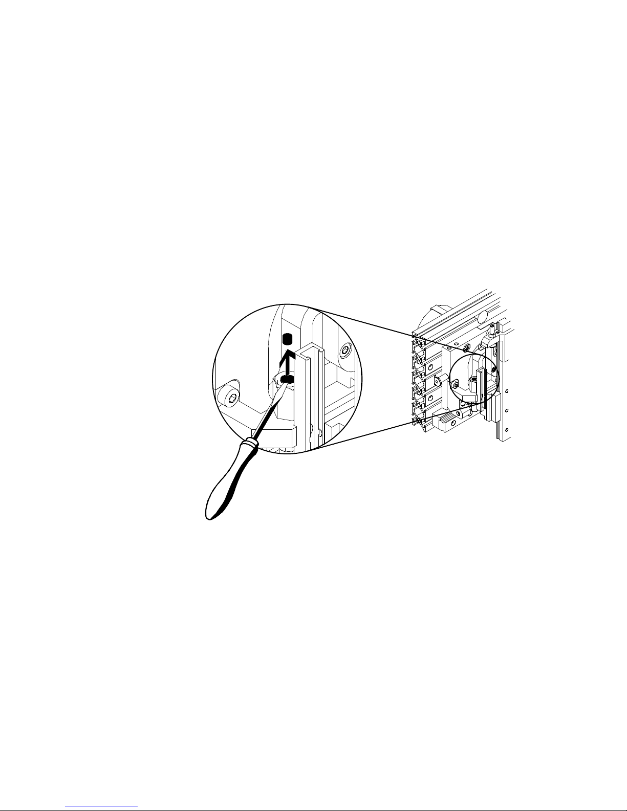
Replacing the rubber buffers in the fixed stops (HSP-...-AS):
1. Switch off the power supply of the drive.
2. Remove the protective cover.
3. Use a suitable tool to remove the rubber buffer of the fixed stop (e.g. screwdri
4. Press the new rubber buffer into the fixed stop.
5. Fasten the protective cover.
ver, pliers).
Fig. 25
Festo HSP-...-AP/AS 2017-10b English
25

HSP-...-AP/A S
11 Accessories
Designation Type
Protective cover kit BSD-HSP-12 BSD-HSP-16 BSD-HSP-25
Installation kit MKRP-1 MKRP-2 MKRP-3
Adapter kit HAPG-70 HAPG-71 HAPG-72
HSP-12-... HSP-16-... HSP-25-...
Waiting position, right BWR-HSP-12 BWR-HSP-16 BWR-HSP-25
Waiting position, left BWL-HSP-12 BWL-HSP-16 BWL-HSP-25
Shock absorber YSRW-5-8 YSRW-7-10 YSRW-8-14
Spring clamping element Original spare part for HSP
Connecting kit
Connecting bracket
Sliding block HMBN-5-M5
Proximity switch SME-8-K(S)-LED-24
Start-up valve HEL-... or HEM-...
One-way flow control valve
(restricted exhaust)
HMBK-ND
HMBV-ND
SMT-8-PS(NS)-K(S)-LED-24-B
GRLA-...
Instructions on fitting further accessories in conjunction with Festo components
are summarized in the system manual “Handling technology.”
26
Festo HSP-...-AP/AS 2017-10b English

HSP-...-AP/A S
12 Eliminating faults
Fault Possible cause Remedy
Hard knocking in
stroke end position
Faults in position
scanning
End positions not
reached
The double rollers
do not run smoothly
in the path guide
Shock absorber defective Replace shock absorber
Stop element overloaded
Reduce speed
– Work load too heavy
– Speed of moveable mass
too high
Position of proximity switch
incorrect
Incorrect type of proximity
switched used
Correct position of proximity
switch
Use only proximity switches of
type SME/SMT-8-...
Proximity switch defective Replace proximity switch
Ferritic parts in vicinity of
proximity switch
Setting of the y-stroke and the
z-stroke not correct
Use parts made of
non-magnetic materials
Adjust end positions
(seechapter “Fitting”)
Link parts offset Align link parts free of offset
(see chapter Fitting, “Setting
the y-stroke”)
Play of the vertical
guide rail in the end
positions
Festo HSP-...-AP/AS 2017-10b English
Spring clamping element
defective
Replace spring clamping
elements
27

HSP-...-AP/A S
13 Technical specifications
Type HSP-12-... HSP-16-... HSP-25-...
Part no. -AP 533 599 533 607 533 615
-AP-SD 533 600 533 608 533 616
-AS 533 605 533 613 533 621
-AS-SD 533 606 533 614 533 622
Design -AP Handling module with pneumatic swivel drive
(double-acting swivel vane)
-AP-SD With pneumatic swivel drive and protective cover
-AS Without drive
-AS-SD Without drive, with protective cover
Weight [kg]
-AP 1.9 3.3 6.4
Basic design
-AP-SD 2.6 4.6 7.6
Increases in weight due to
accessories can be found in the
relevant documentation.
-AS 1.8 3.1 6.2
-AS-SD 2.5 4.3 7.4
Medium -AP-... Filtered, lubricated or non-lubricated
compressed air (filter fineness min. 40 ìm)
Permitted operating pressure -AP-... Min. 4 ... max. 8 bar
Pneumatic connection -AP-... M5
Permitted temperature range 0 ... + 60 C
Vibration
tested as per DIN/IEC 68/EN 60068 part 2-6
Severity class 2
– 0.35 mm path at 10...60 Hz
– 5 g acceleration at 60...150 Hz
Shock
tested as per DIN/IEC 68/EN 60068 part 2-27
Mounting position As desired (vertical operation preferred)
28
Severity class 2
– ± 30 g at 11 ms duration
– 5 shocks in each direction
Festo HSP-...-AP/AS 2017-10b English

HSP-...-AP/A S
Type HSP-25-...HSP-16-...HSP-12-...
Lubrication Cross guide with service life lubrication,
re-lubrication recommended after 10 million
strokes.
End position adjustment Adjusting screws in the y-direction
Stop screws in the z-direction
End position cushioning with shock absorber YSRW-5-8 YSRW-7-10 YSRW-8-14
Permitted shock absorber energy
E
max
E
hmax
[Nm]
[kNm]
1
10
2
15
3
21
Min. permitted pulse time [s]
Pulse time t
= positioning time t + dwell time t
t
0.6 0.8 1
e
(definition see chapter 7)
Stroke ranges
y-stroke [mm] 52...68 90...110 130...170
z-stroke [mm] 20...30 35...50 50...70
Max. permitted loading values of the cross
guide
Dynamic torque M
per
[Nm]
*)
1.1 2.4 3.2
with vertical operation and observation of the
maximum work load
Static torque M
0per
[Nm]
M
M
per
*)
5 10 15
M
x
)
M
per
M
y
)
M
per
z
v 1
with vertical operation
for press-fit and joining procedures without
dynamic loading
M
M
0x
0per
)
M
M
0y
0per
)
M
M
0z
0per
v 1
*)
The torques refer to the centre of the cross guide.
Festo HSP-...-AP/AS 2017-10b English
29

HSP-...-AP/A S
Type HSP-12-... HSP-16-... HSP-25-...
Max. permitted loading with external drive
Axial force on drive shaft F
Radial force on drive shaft F
Drive torque M
[Nm] 1.25 2.5 5
Yper
Noise emission as per DIN 45635
LpAeq [dBA]
[N] 18 30 50
Yper
[N] 45 75 120
Zper
*)
64 67 73
Sound pressure level as per aural reception,
(corresponds to continuous sound level DIN IEC 804)
LpAIm [dBA]
75 78 84
Pulse holding of positioning sounds, (corresponds to
pulse continuous sound level DIN IEC 804)
*)
Measured at maximum stroke 6 bar; pulse frequency 1/s; additional mass 0.3 kg;
frequence assessment A
30
Festo HSP-...-AP/AS 2017-10b English

HSP-...-AP/A S
14 Materials
Component Materials
– Sub-base
Al wrought alloy, anodized
– Shock absorber support
– Segment (between the stop screws)
– Sensor rail
– Housing
– Link
Hardened steel, burnished
– Swivel lever
– Stop screw
Steel, high alloy
– Stop sleeve
– Clamping element
Cross guide Tempered steel
Additional materials for HSP-AS-...
Shaft Steel
Storage Al wrought alloy
Ball bearing Roller bearing steel
Festo HSP-...-AP/AS 2017-10b English
31

HSP-...-AP/A S
15 Characteristic curves
a) Positioning time t as a factor of the work load m
Definition
Work load m = additional mass on the vertical guide rail
e.g. adapter, swivel drive, gripper and work item
Positioning time t = time which the HSP-... requires in order to move from the
receive position to the release position and back.
m [kg]
a) Mass moment of inertia J as a factor of the work load m
(for drive design)
J [kgcm2]
32
t [ms]
m [g]
Festo HSP-...-AP/AS 2017-10b English

HSP-...-AP/A S
Festo HSP-...-AP/AS 2017-10b
33

Copyright:
Festo AG & Co. KG
Ruiter Straße 82
73734 Esslingen
Germany
Phone:
+49 711 347-0
Fax:
+49 711 347-2144
Reproduction, distribution or sale of this document or communica
tion of its contents to others without express authorization is
prohibited. Offenders will be liable for damages. All rights re
served in the event that a patent, utility model or design patent is
registered.
E-mail:
service_international@festo.com
Internet:
www.festo.com
 Loading...