

Page 1

Antriebslose Führungsachse
Driveless guide axis
FDG−...−ZR−RF
(de) Bedienungs−
anleitung
(en) Operating
instructions
(es) Instrucciones
de utilización
(fr) Notice
d’utilisation
(it) Istruzione
per l’uso
(sv) Bruksanvisning
682 178
0404NH
Page 2

FDG−...−ZR−RF
Esbedeuten/Symbols/Símbolos/
Symboles/Simboli/Teckenförklaring:
Warnung
Warning, Caution
Atención
Avertissement
Avvertenza
Varning
Hinweis
Please note
Por favor, observar
Note
Nota
Notera
Umwelt
Antipollution
Reciclaje
Recyclage
Riciclaggio
Återvinning
Zubehör
Accessories
Accesorios
Accessoires
Accessori
Tillbehör
Einbau und Inbetriebnahme nur von qualifi
ziertem Fachpersonal, gemäß Bedienungs
anleitung.
Fitting and commissioning to be carried out by
qualified personnel only in accordance with
the operating instructions.
El montaje y la puesta en funcionamiento,
debe ser realizado exclusivamente por perso
nal cualificado y siguiendo las instrucciones
de utilización.
Montage et
mise en service uniquement par
du personnel agréé, conformément aux
instructions d’utilisation.
Montaggio e messa in funzione devono essere
effettuati da personale specializzato ed auto
rizzato in confomità alle istruzioni per l’uso.
Montering och idrifttagning får endast utföras
av auktoriserad fackkunnig personal i
enlighet med denna bruksanvisning.
Deutsch 3. . . . . . .
English 15. . . . . . . . . . . . . . . . . . . . . . . . . . . . . . . . . . . . .
Español 27. . . . . . . . . . . . . . . . .
. . . . . . . . . . . . . . . . . . . . . . . . . . . . . . . . . . . . . . . . . . . . . . . . . . . . . . . . . . . . . . .
. . . . . . . . . . . . . . . . . . . . . . . . . . . . . . . . .
. . . . . . . . . . . . . . . . . . . . . . . . . . . . . . . . . . . . . . . . . . . . . . . . . . . .
Français 39. . . . . . . . . . . . . . . . . . . . . . . . . . . . . . . . . . . . . . . . . . . . . . . .
Italiano 51. . . . . . . . . . . . . . . . . . . . . . . . . . . .
Svenska 63. . . . . . . .
2
. . . . . . . . . . . . . . . . . . . . . . . . . . . . . . . . . . . . . . . . . . . . . . . . . . . . . . . . . . . . .
. . . . . . . . . . . . . . . . . . . . . . . . . . . . . . . . . . . . . . . . . .
. . . . . . . . . . . . . . . . . . . . .
Festo FDG−...−ZR−RF 0404NH
Page 3

FDG−...−ZR−RF
Antriebslose Führungsachse FDG−...−ZR−RF Deutsch
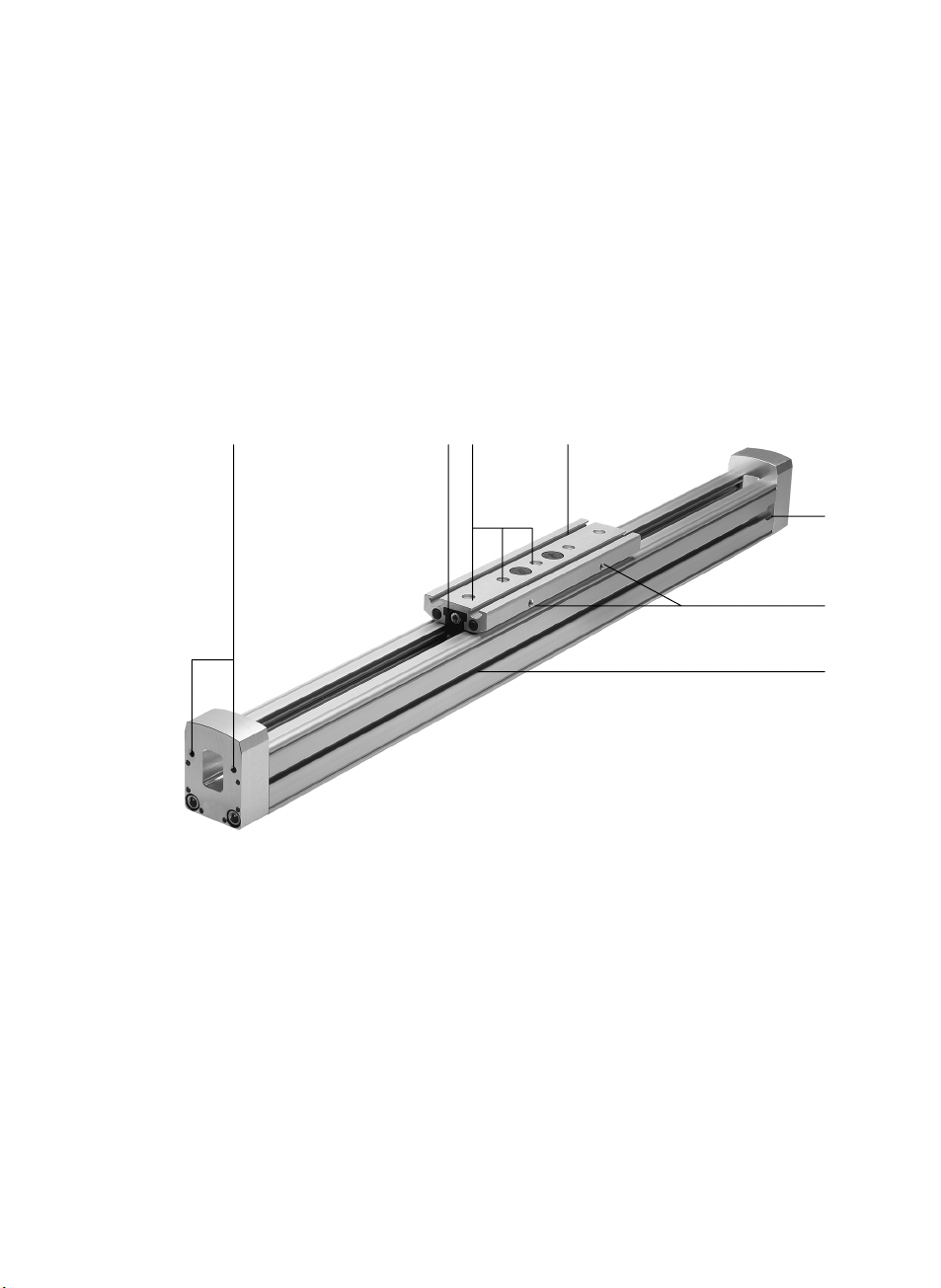
1 Bedienteile und Anschlüsse
1234
5
6
7
Innengewinde zur Befestigung der Achse
1
2 Schmiernippel
3 Zentriersenkungen mit bzw. ohne Befestigungsgewinde
4 Nut zur Befestigung der Nutzlast
5 Ausfräsung zum Einführen von Nutensteinen (nur Baugröße 25)
6 Innengewinde zur Befestigung einer Schaltfahne
7 Nut zur Befestigung der Sensorhalter
Bild1
Festo FDG−...−ZR−RF 0404NH Deutsch
3
Page 4
FDG−...−ZR−RF
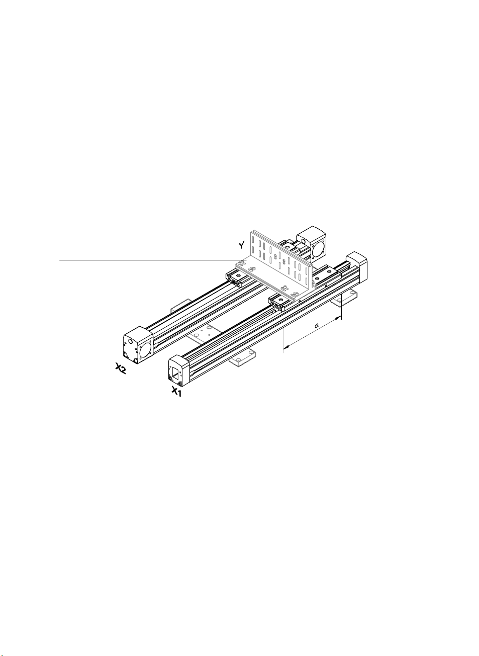
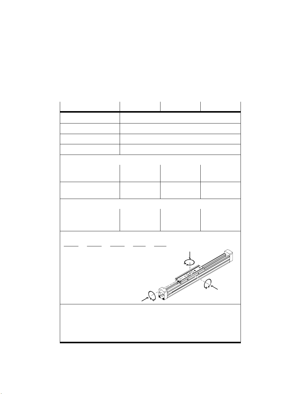
2 Funktion
Die Läufer der Führungsachse stützen eine Last beweglich ab.
Bei Verschiebung der Last entlang der Achsrichtung folgt der Läufer sehr
leichtgängig.
Ein verlängerter Läufer erlaubt eine Belastung mit höheren Momenten.
8
Bild2: Prinzipdarstellung
8 Brücke (Querverbindungsbausatz)
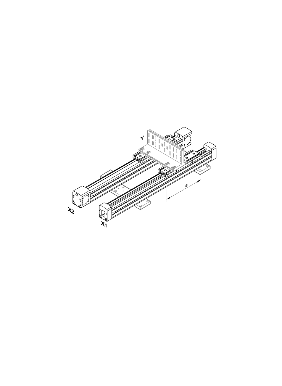
3 Anwendung
Bestimmungsgemäß dient die FDG−...−ZR−RF zum Grundaufbau von Ausleger− oder
Portalsystemen bestehend aus einer antreibenden Linearachse und einer antriebs
losen Führungsachse.
4
Festo FDG−...−ZR−RF 0404NH Deutsch
Page 5

FDG−...−ZR−RF
4 Voraussetzungen für den Produkteinsatz
Hinweis
S Stellen Sie sicher , dass die Punkte dieses Kapitels immer eingehalten werden.
Dies macht das Produktverhalten ordnungsgem ä ß und sicher.
S Vergleichen Sie die Grenzwerte in dieser Bedienungsanleitung mit Ihrem
aktuellen Einsatzfall (z.B. Kräfte, Massen, Temperaturen, Momente).
Nur die Einhaltung der Belastungsgrenzen ermöglicht ein Betreiben des
Artikels gemäß der einschlägigen Sicherheitsrichtlinien.
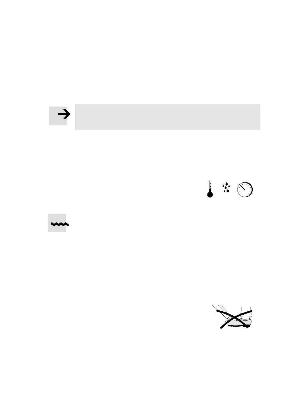
S Berücksichtigen Sie die Umgebungs−
bedingungen vor Ort.
Korrosive Umgebungen beeinträchtigen
die Lebensdauer Ihres Produkts.
S Entfernen Sie die Verpackungen vom Produkt.
Die Verpackungen sind vorgesehen für eine Verwertung auf stofflicher Basis
(Ausnahme: Ölpapier = Restmüll).
Bild3
[°C] [%] [mbar]
S Beachten Sie die Vorschriften für Ihren Einsatzort (z.B. von Berufsgenossen
schaften oder nationalen Institutionen).
S Verwenden Sie das Produkt im Originalzustand ohne jegliche eigenmächtige
Veränderungen.
S Stellen Sie sicher, dass Schutzmaßnahmen nicht umgangen werden können.
5 Transport und Lagerung
S Berücksichtigen Sie das Gewicht der
FDG−...−ZR−RF.
Sie wiegt bis zu 100 kg.
S Fixieren Sie den Läufer, der sehr leichtgängig ist, bei Bedarf mit Klebeband.
Festo FDG−...−ZR−RF 0404NH Deutsch
Bild4
5
Page 6

FDG−...−ZR−RF
6 Einbau
Mechanisch
S Stellen Sie sicher, dass diese Bedingung eingehalten wird:
Nennhub FDG−...−ZR−RF ţ Nennhub Antriebsachse
Beispiel (Typenschilder): FDG−40−800
−ZR−RF ţ DGE−40−800−ZR−RF
Nur so funktioniert das Mehrachssystem in den Endlagen kollisionsfrei.
S Beachten Sie, dass der Nennhub je nach Achse und Hersteller unterschiedlich
definiert sein kann:
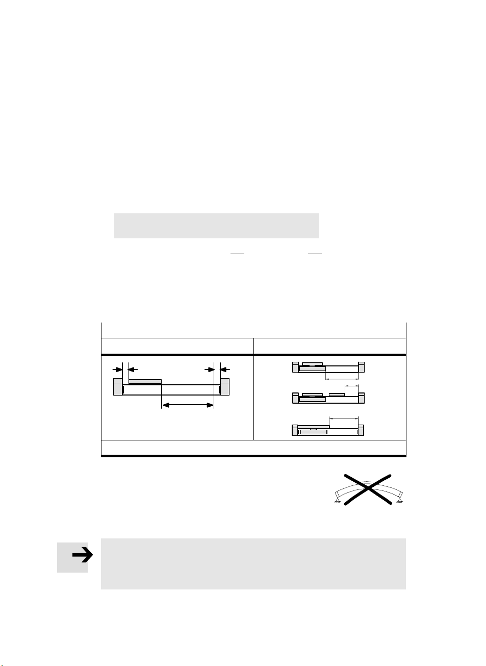
Definition des Nennhubs
bei FDG−...−ZR−RF und DGE−...−ZR−RF: bei anderen Achsen/Herstellern:
r
h: Nennhub r: Hubreserve
r
h
h
h
h
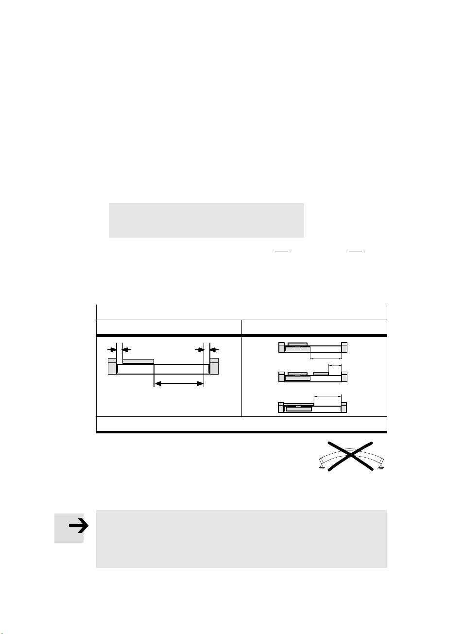
S Platzieren Sie die FDG−...−ZR−RF ohne
Verspannungen und Biegungen.
(Ebenheit der Anbaufläche: 0,2 mm / 30 cm).
Hierzu dienen Achsbefestigun gs bausätze ,
Bild5
Mittenstütz e n und Fußbefestigungen.
Hinweis
Berücksichtigen Sie, dass die Befestigung der Achse bei hohen Belastungen
nicht ausschließlich an den Abschlussdeckeln erfolgen darf.
Zu hohe Zugbelastungen führen zum Ausreißen der Deckelschrauben.
6
Festo FDG−...−ZR−RF 0404NH Deutsch
Page 7
FDG−...−ZR−RF
10
9
8
F[kg]
7
6
5
4
FDG−25−ZR−RF
3
2
1
0
1200 1500 1800 2100 2400 2700
100
90
80
F[kg]
70
60
50
40
FDG−63−ZR−RF
30
20
10
0
1600 2800 3200 3600 40002000 2400
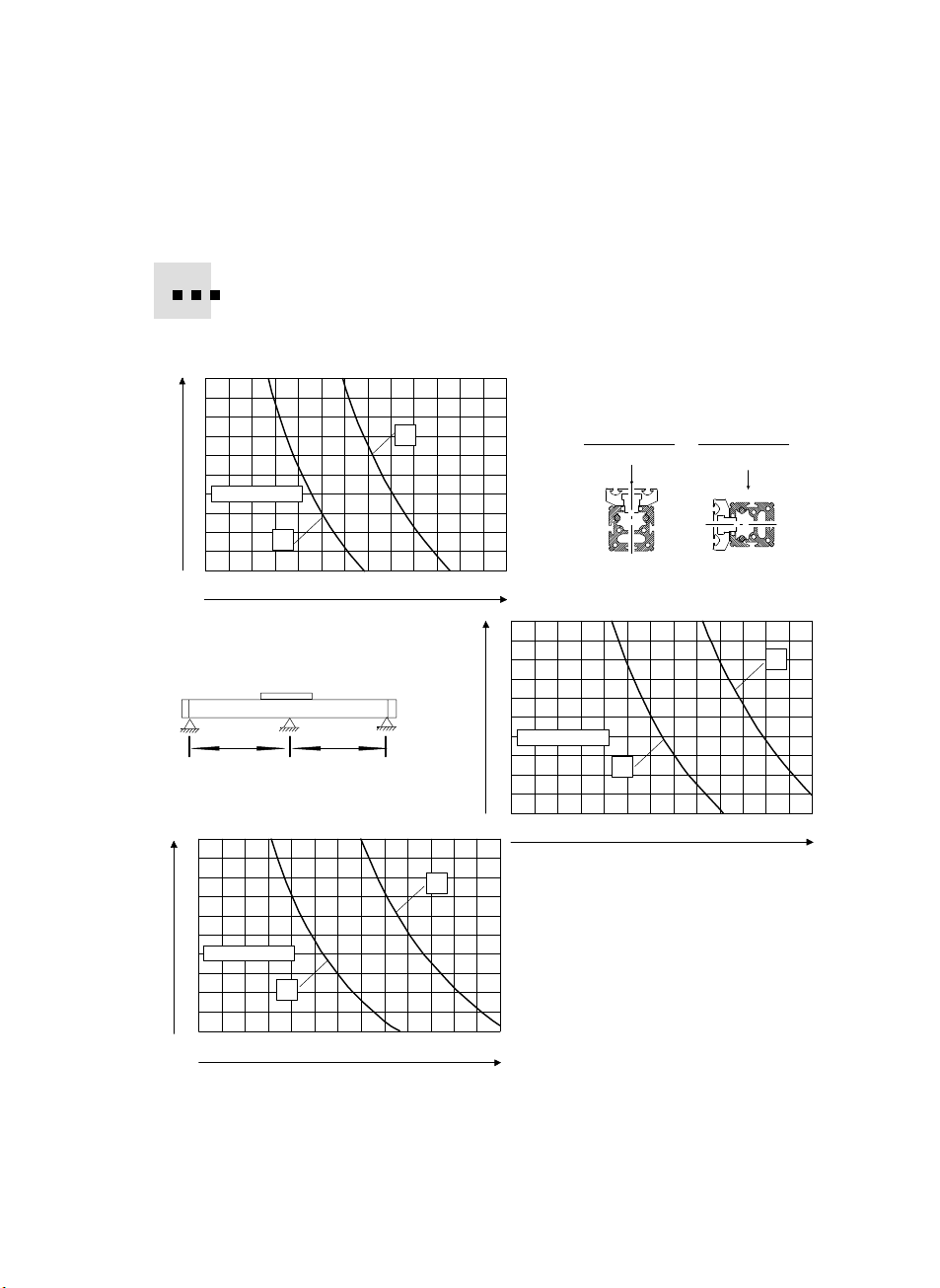
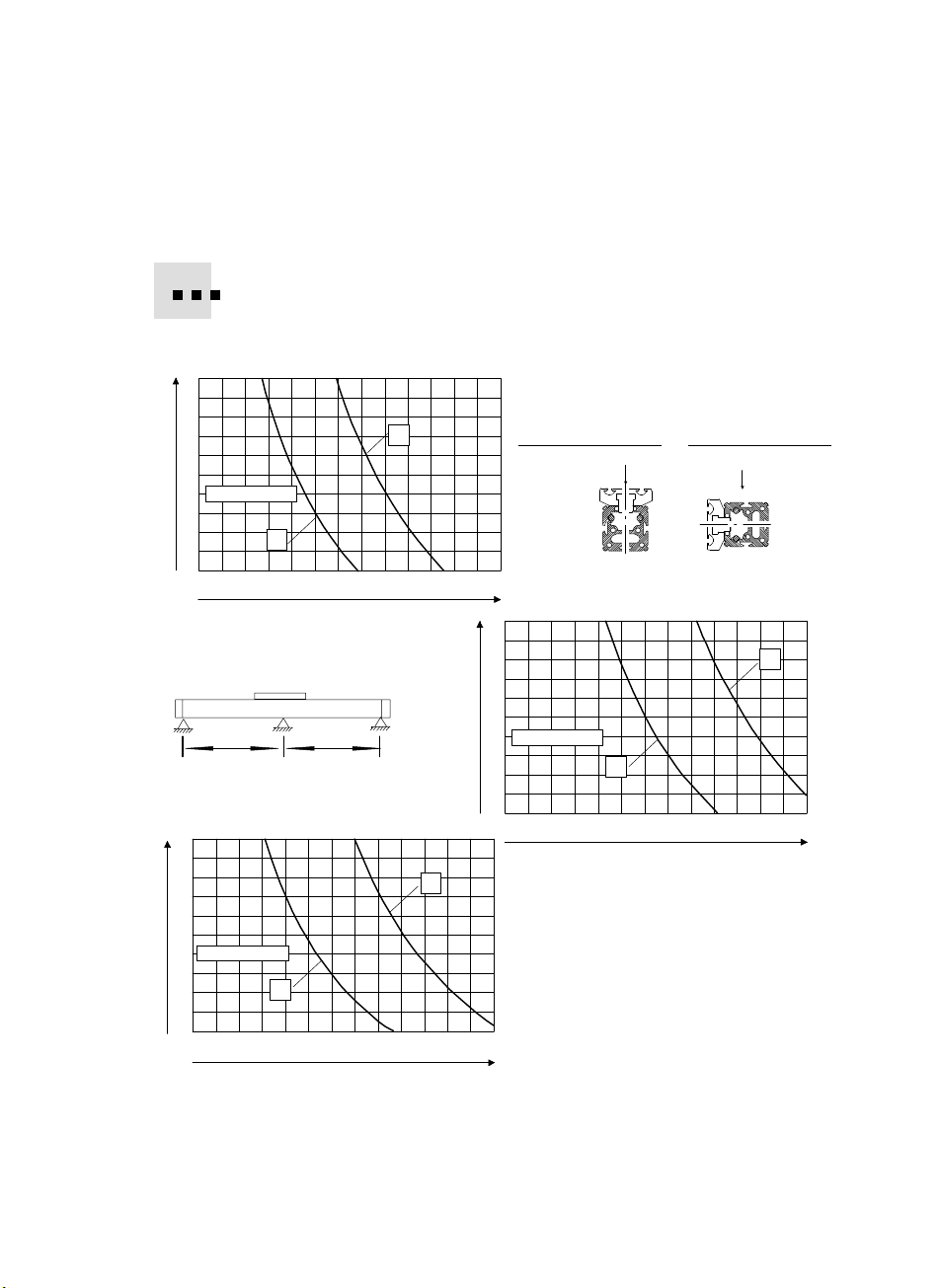
Bei Artikeln mit großen Hublängen:
S Verwenden Sie die Mittenstütze Typ MUP−... .
Bild 6 zeigt die Stützabstände, die jeweils erforderlich sind.
x
y
LL
y
x
L[mm]
3000
25
22,5
F[kg]
20
17,5
15
12,5
10
FDG−40−ZR−RF
7,5
5
2,5
0
1200 1500 1800 2100 2400 2700 3000
Einbaulagex
Bild6:
Notwendige Stützabstände L für
FDG−...−ZR−RF in Abhängigkeit von
L[mm]
Einbaulage, Nenngröße und Nutzlast F
Einbaulagey
F
y
F
x
L[mm]
Festo FDG−...−ZR−RF 0404NH Deutsch
7
Page 8

FDG−...−ZR−RF
УУУУУ
УУУУУ
УУУУУ
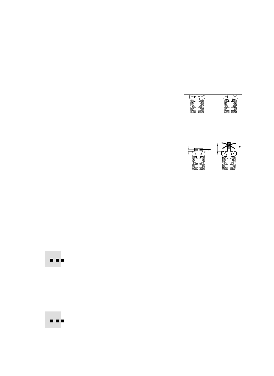
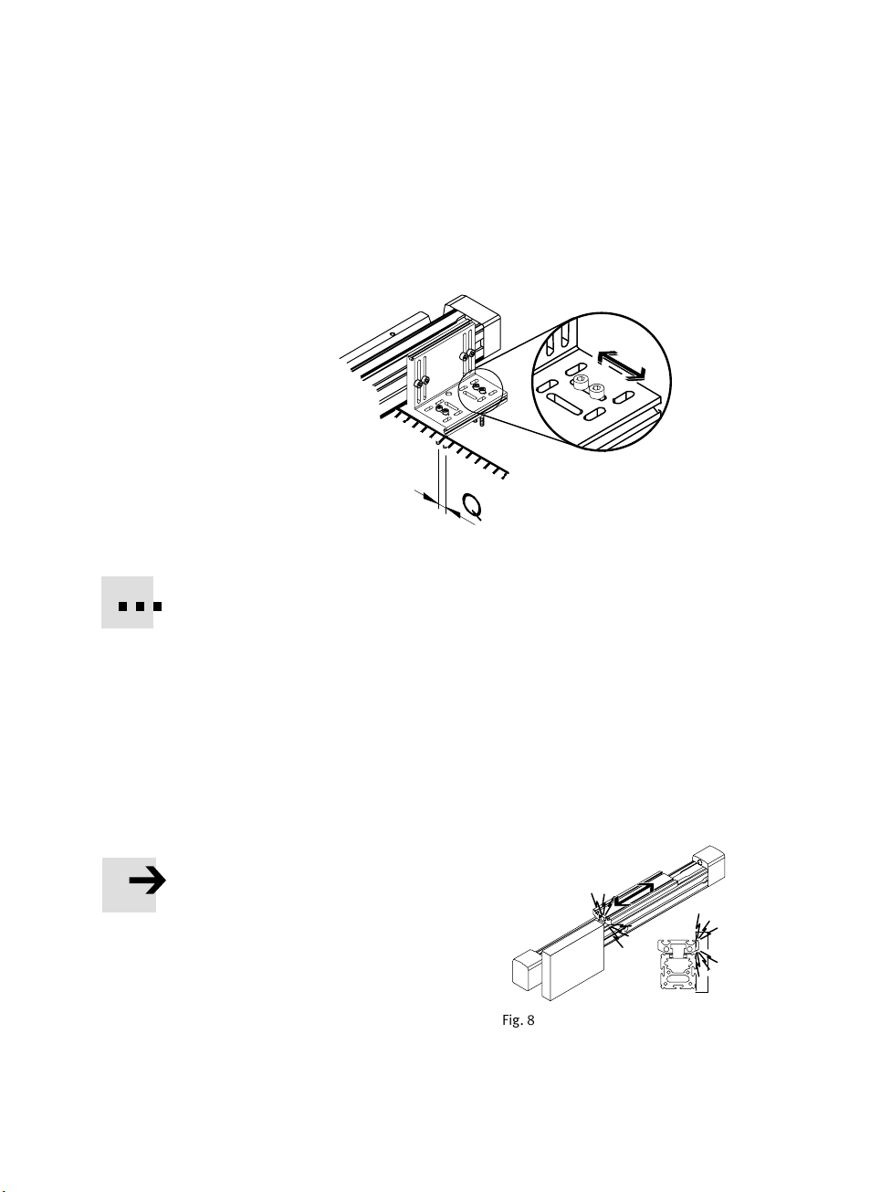
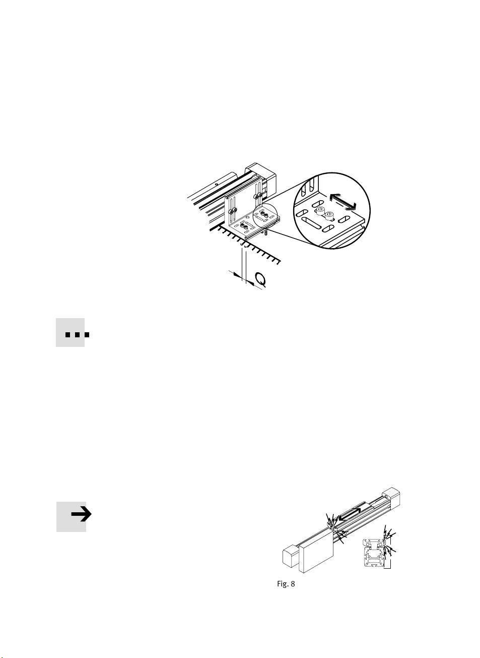
S Befestigen Sie Achsbefestigungsbausätze oder Mittenstützen an der
FDG−...−ZR−RF nach folgendem Bild:
Bild7: Q = Spiel für Querbefestigung
Als Befestigungsvorrichtung dienen gegebenenfalls Nutensteine in den
Profilnuten.
8
Bei Verwendung von FDG−...−ZR−RF in Verbindung mit einer Antriebsachse DGE−...
oder DGP(L)−...:
S Verwenden Sie die Stützabstände der Antriebsachse auch für die FDG−...−ZR−RF.
So vermeiden Sie Verspannungen auf Grund ungleicher Durchbiegungen.
S Drehen Sie die Befestigungsschrauben
für die Querbefestigung zunächst nur
leicht fest (siehe Bild 7: Q).
Dadurch lässt sich die FDG−...−ZR−RF im weiteren Einbau noch ausrichten.
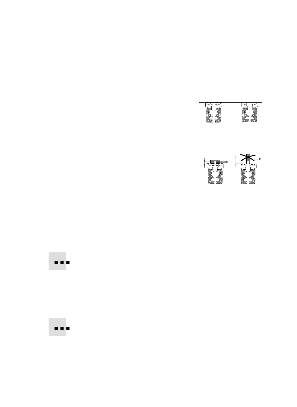
Beim Anbau der Befestigungselemente:
S Stellen Sie sicher, dass sich der Achs−
befestigungsbausatz bzw. die Mitten−
stützen außerhalb des Kollisionsbereichs
des Läufers befinden, indem sie den Läu
fer einmal über den gesamten Verfahrweg
verschieben.
Bild8
Festo FDG−...−ZR−RF 0404NH Deutsch
Page 9
FDG−...−ZR−RF
d
Bei Verwendung von FDG−...−ZR−RF in Verbindung mit einer Antriebsachse DGE−..
oder DGP(L)−...:
1. Sorgen Sie dafür, dass die Läuferflächen
beider Achsen innerhalb des gesamten
Verfahrhubs auf gleicher Höhe liegen.
2. Positionieren Sie die FDG−...−ZR−RF exakt
parallel ausgerichtet zur Antriebsachse.
3. Platzieren Sie die Brücke (s. Bild 2) und
die Nutzlast folgendermaßen auf den
Läufern von FDG−...−ZR−RF und Antriebsachse:
Kippmoment aus der Kraft F paral
Das
lel zur Zylinderachse und dem Abstand
d bleibt klein.
Hierbei beinhaltet die Kraft F auch die
Trägheitskraft F = m ⋅ a, die Gewichts
kraft und mögliche externe Kräfte.
Es wirken nur Belastungen im Rahmen
der zulässigen Werte (siehe Technische
Daten).
4. Schieben Sie die Brücke über die gesamte Hubstrecke
indieandere.
Dabei positioniert sich die Führungsachse verspannungsfrei zur Antriebs
achse.
5. Drehen Sie die Befestigungsschrauben (siehe Bild 7: Q) der Führungsachse
fest.
Bild9
F
Bild10
von einer Endlage
d
F
Prüfen Sie, ob Stoßdämpfer oder Anschläge zusätzlich extern erforderlich sind.
Zur Abfrage der Läuferpositionen:
S Verwenden Sie Sensoren mit induktivem Schaltprinzip in Verbindung mit
ferritischen Schaltfahnen.
S Vollziehen Sie den Einbau der
der Sensoren sowie der Antriebsachse.
Ungenutzte Sensornuten schützen Sie am besten mit Abdeckschienen laut
Kapitel Zubehör" vor Schmutzablagerungen.
Festo FDG−...−ZR−RF 0404NH Deutsch
Sensoren gemäß der Bedienungsanleitungen
9
Page 10
FDG−...−ZR−RF
7 Inbetriebnahme, Bedienung und Betrieb
Warnung
S Stellen Sie sicher, dass im Verfahrbereich
des Artikels
niemand in die Laufrichtung der
bewegten Bauteile greift (z.B. durch
Schutzgitter)
sich keine Fremdgegenstände
befinden.
Erst bei völligem Stillstand der Masse
darf ein Greifen an die FDG−...−ZR−RF
möglich sein.
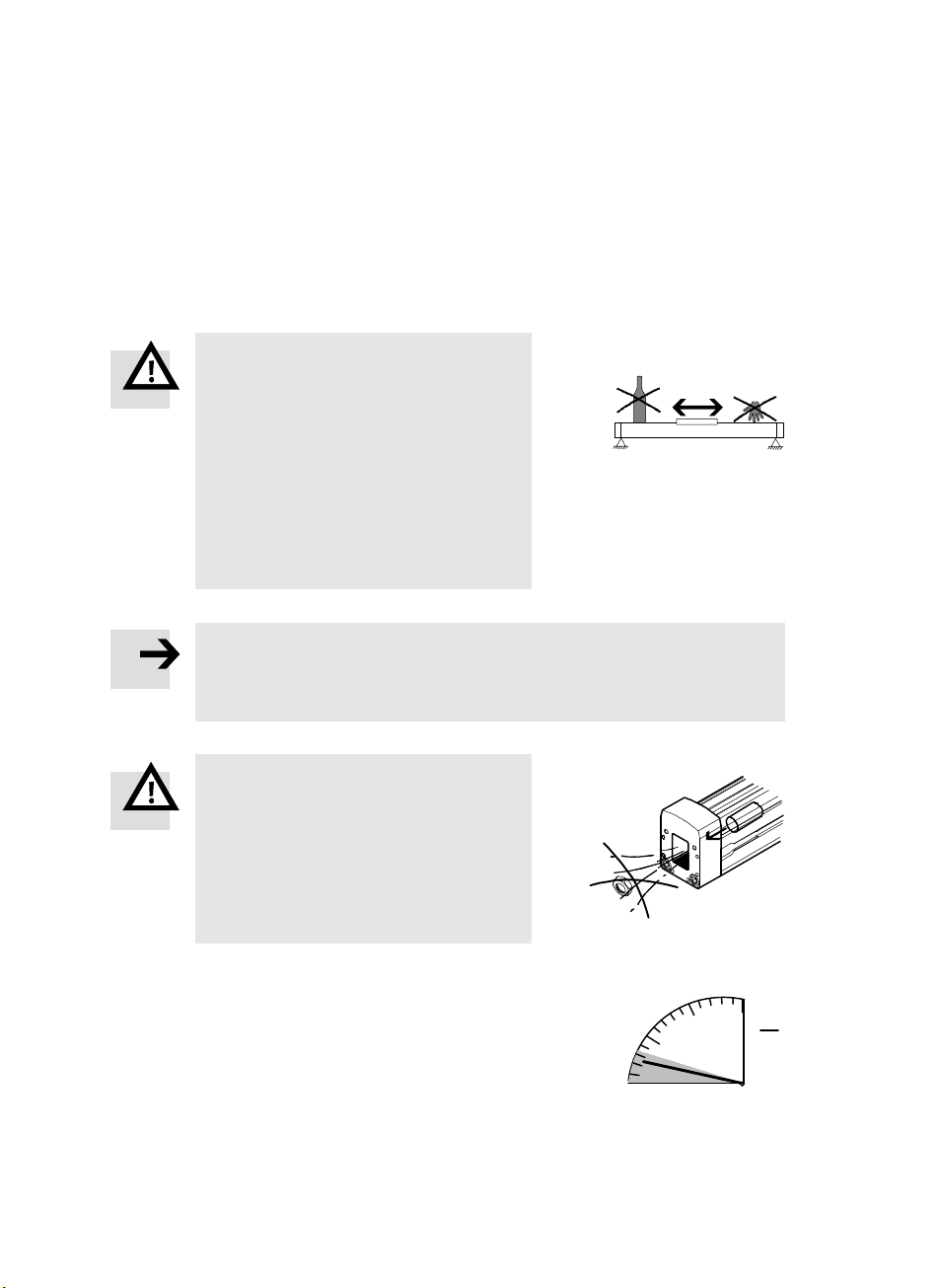
Hinweis
Die Ausfräsungen in den Abschlussdeckeln ermöglichen, dass Fremdkörper
(z.B. Muttern oder Schrauben), die versehentlich in den Schlitz gefallen sind,
nach außen gelangen.
Bild11
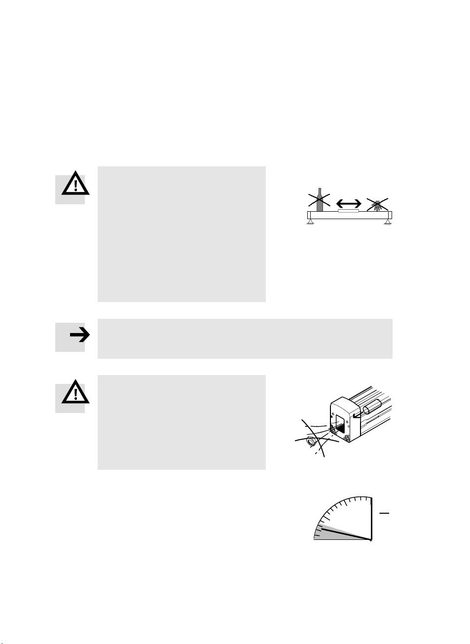
Warnung
An den Abschlussdeckeln nach außen
geschleuderte Gegenstände können
Personen oder Gegenstände verletzen
bzw. beschädigen.
Bild12
S Stellen Sie sicher, dass in der Verlänge
rung der FDG−...−ZR−RF niemand getroffen
werden kann (z.B. durch Schutzgitter).
S Bestromen Sie den Antriebsmotor
2000
3000
zunächst mit Begrenzung auf geringe
Drehzahlen und Momente.
Dann durchfährt der Läufer zunächst den
gesamten Verfahrweg langsam.
Bild13
10
1000
0
Festo FDG−...−ZR−RF 0404NH Deutsch
U
min
Page 11
FDG−...−ZR−RF
8 Wartung und Pflege
S Empfehlung:
Schicken Sie den Artikel alle 10.000 Laufkilometer zur Inspektion an Festo.
S Lassen Sie Schrauben und Gewindestifte, für die es keine unmittelbare Auf−
forderung zur Veränderung in dieser Bedienungsanleitung gibt, unverändert.
Zum Ölen der Rollenführung
S Schmierintervall: bei Bedarf, theoretisch spätestens alle 10.000 km.
S Beachten Sie, dass die Schmierintervalle verkürzt werden müssen bei
staubiger und schmutziger Umgebung,
sehr kurzen Arbeitshüben (Einlaufen an einer Position).
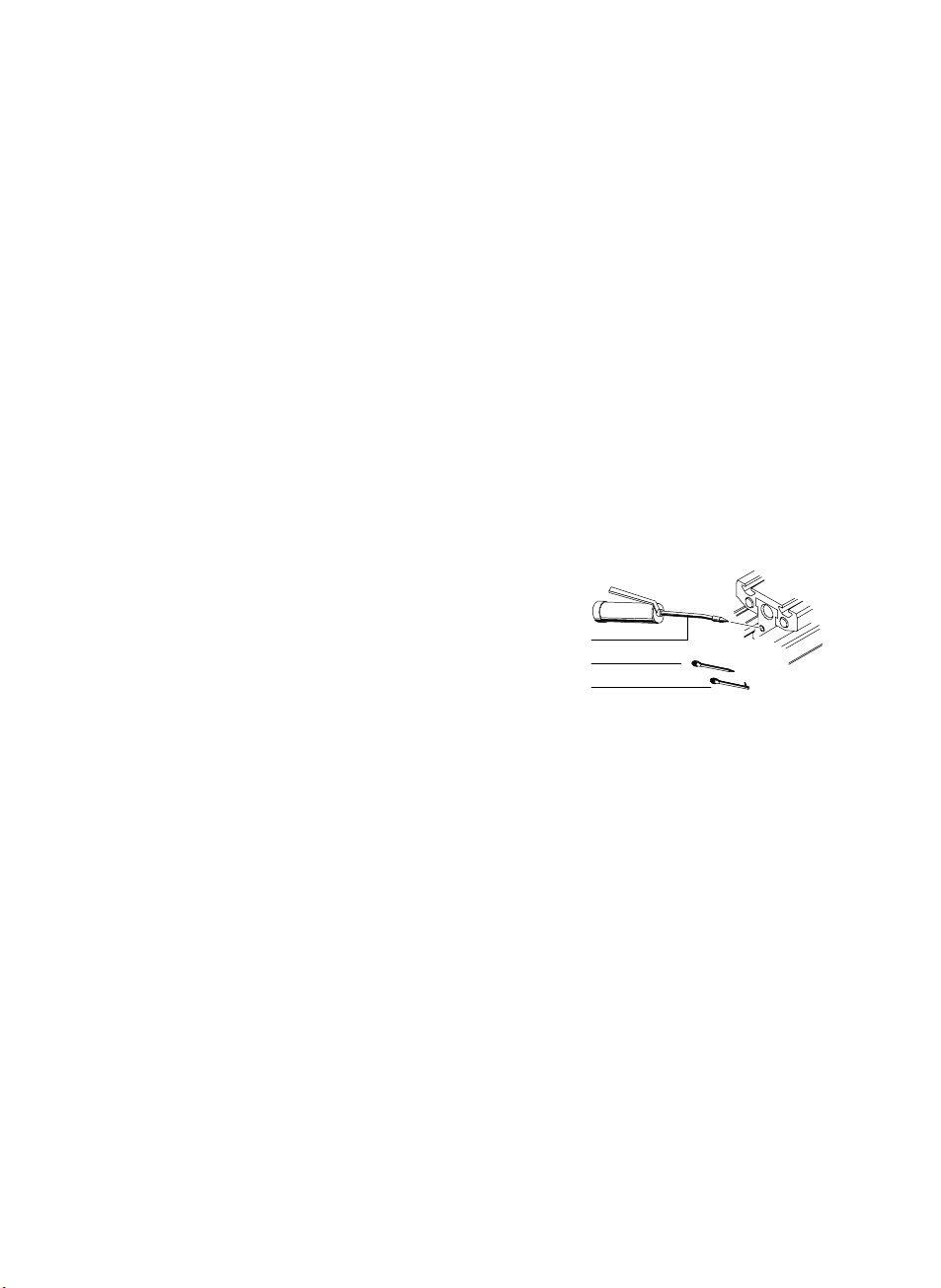
S Ölen Sie die FDG−...−ZR−RF auf beiden Sei
ten des Läufers an den Schmiernippeln.
Öl: z.B. Constant OY 390 Fa. Klüber, Mün
chen
Fettpresse: siehe Kapitel Zubehör
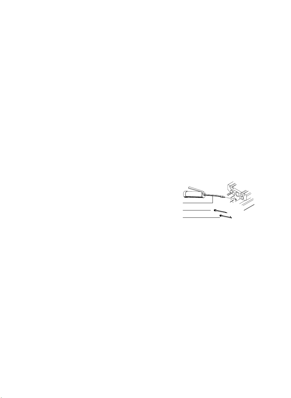
Bei beengten Platzverhältnissen:
S Verwenden Sie die Düsenrohre B
gang axial) oder C (Ausgang radial)
anstelle des Standard−Düsenrohrs A.
S Verfahren Sie den Nennhub danach einmal vollständig, damit sich das Öl
gleichmäßig im Inneren der FDG−...−ZR−RF verteilt.
Bei jedem Wartungsvorgang:
S Prüfen Sie, ob der Läufer spiel− und verspannungsfrei eingestellt ist.
Bei Auffälligkeiten siehe Kapitel Störungsbeseitigung.
9 Reparatur
Bei Störungen im Betriebsablauf:
S Sorgen Sie dafür, dass eine Überholung der FDG−...−ZR−RF nur durch unseren
Reparaturservice vorgenommen wird (z.B. bei Spiel zwischen Läufer und
Führung).
Dadurch vermeiden Sie Spätschäden an Ihrer Achse. Die Reparaturvorgänge
erfordern Einstellarbeiten mit sehr feinen Abstimmungen.
:
A
B
C
(Aus
Bild14
Festo FDG−...−ZR−RF 0404NH Deutsch
11
Page 12

FDG−...−ZR−RF
10 Zubehör
Typ Bezeichnung
MUP−... Mittenstütze
HP−... Fußbefestigung
HMAV−... Adapterbausatz HMP−...
HMSV−... Adapterbausatz SLT−...
HMVA−... Aktoradapterbausatz
HMVD−... Tandemauslegerbausatz
HMVG−... Achsverbindungsbausatz (für Achsabstände Ţ 200 mm)
HMVJ−... Justierbausatz
HMVK−... Kreuzverbindungsbausatz
HMVS−... Tandemstützbausatz
HMVT−... Tandembausatz
HMVV−... Verstärkerbausatz
SIEN−... Sensor mit Schließer− / Öffner−Funktion
HWS−... Sensorhalter
SF−... Schaltfahne
SIM−... Verlängerungskabel
ZBH−... Zentrierhülsen
NST/NSTL−... Nutensteine
ABP−... Nutenabdeckschiene
647 958 Fettpresse mit Nadel−Spitzmundstück
647 959 Düsenrohr, Ausgang axial
647 960 Düsenrohr, Ausgang radial
Bild15
12
Festo FDG−...−ZR−RF 0404NH Deutsch
Page 13

FDG−...−ZR−RF
11 Störungsbeseitigung
Störung Ursache Abhilfe
Auffällige Laufgeräusche
und schwergängiger Läufer
Rot−braune Farbe an den
Führungsstangen
Fühlbares Spiel am Läufer Verschleiß, Beschädigung Den Artikel an Festo
Schwergängigkeit einer
Tandemanordnung nahe
der Endlage
Einrasten" an einer
Position
Schwingungen Überlastung der Achse Maximale Belastungswerte
Fehlende oder undefinierte
Schaltfunktionen
Mangel−Schmierung der
Läuferlagerung
Rost durch Mangel−
schmierung
Mangelnde Parallelität
zwischen Antrieb und
FDG−...−ZR−RF
lange Stillstandszeit Verliert sich nach einer
Zu hohe Dynamik Veränderungen zur
Falsche Anordnung des
Schwerpunktes der
Nutzlast
Externe Einkopplung am
Grundgestell oder im
Mehrachssystem
Näherungsschalter oder
Kabel defekt
Ölen, bei Bedarf an Festo
schicken
schicken
Achsen neu ausrichten
Einlaufphase wieder
einhalten
Projektierung prüfen
Schwerpunkt verlegen
Einkopplung beseitigen
Defektes Teil ersetzen
Festo FDG−...−ZR−RF 0404NH Deutsch
Anbau Sensorhalter oder
Schaltfahne falsch
Schaltabstand falsch
eingestellt
Schalter oder Anschluss
falsch
Anbau korrigieren
Neu justieren
Falsches Teil ersetzen
13
Page 14

FDG−...−ZR−RF
12 Technische Daten
FDG−25−ZR−RF FDG−40−ZR−RF
Bauart Antriebslose Führungsachse mit Rollenführung
Temperatur 0 ... + 60 °C (Lagerung/Betrieb)
Einbaulage Beliebig
Läufergeschwindigkeit max. 10 m/s
Zulässige Nutzlast
waagrecht
senkrecht
Zulässige Querlast
FY, F
Z
Zulässige Momentenbelastung: (Klammerwerte für Variante GV)
Mx [Nm]
My [Nm]
Mz [Nm]
max
)
|My|
My
max
|Mx|
Mx
10 kg
5 kg
150 N 300 N 600 N
7
15 (30)
15 (30)
max
)
Fy
|Fy|
max
)
|Mz|
Mz
)
25 kg
12,5 kg
18
60 (120)
90 (180)
|Fz|
Fz
max
v 1
Mz
FDG−63−ZR−RF
50 kg
25 kg
65
170 (340)
300 (600)
Fz
Mx
Fx
Werkstoffe
Läufer, Zylinderrohr, Deckel: Aluminium
Rollen, Schrauben, Nutensteine: Stahl
Puffer, Abstreifer: Gummi, Filz
Abdeckung des Läufers im Schlitz: IXEF
Führungsstangen: Stahl
14
Festo FDG−...−ZR−RF 0404NH Deutsch
Fy
My
Page 15
FDG−...−ZR−RF
Passive guide axis type FDG−...−ZR−RF English
1 Operating parts and connections
1234
5
6
7
Internal thread for fastening the axis
1
2 Lubrication nipple
3 Centring recesses with or without fastening thread
4 Groove for fastening the work load
5 Slot for inserting the sliding blocks (only size 25)
6 Internal thread for fastening a switching lug
7 Groove for fastening the sensor supports
Fig.1
Festo FDG−...−ZR−RF 0404NH English
15
Page 16

FDG−...−ZR−RF
2 Function
The slides of the guide axis support a load whilst moving.
When the load is shifted along the direction of the axis, the slide follows very
smoothly.
An extended slide enables a loading with higher torques.
8
Fig.2: Basic representation
8 Bridge (transverse connection kit)
3 Application
The FDG−...−ZR−RF has been designed as a basic structure for boom or portal
systems consisting of a driving linear axis and a passive guide axis.
16
Festo FDG−...−ZR−RF 0404NH English
Page 17

FDG−...−ZR−RF
4 Conditions of use
Please note
S Make sure that the specifications in this chapter are always observed.
The product will then function correctly and reliably.
S Compare the maximum values specified in these operating instructions with
your actual application (e.g. forces, masses, temperatures, torques).
Only if the loading limits are observed can the product be operated in
accordance with the relevant safety guidelines.
S Take into account the ambient conditions
at the location.
Corrosive environments will impair the
service life of the product.
S Remove the packing from the product.
The packing is intended for recycling
(except for: oiled paper which must be
disposed of ).
[°C] [%] [mbar]
Fig.3
S Observe the specifications applicable to your location, as
national laws and regulations.
S Use the product in its original state without undertaking any modifications.
S Make sure that safety measures cannot be ignored.
5 Transport and storage
S Consider the weight of the FDG−...−ZR−RF.
It weighs up to 100 kg.
S If necessary fasten the slide, which runs
very smoothly, with adhesive tape.
Festo FDG−...−ZR−RF 0404NH English
well as all local and
Fig.4
17
Page 18
FDG−...−ZR−RF
6 Fitting
Mechanical components
S Make sure that this condition is observed:
Rated stroke FDG−...−ZR−RF ţ Rated stroke drive axis
Example (type plates): FDG−40−800
−ZR−RF ţ DGE−40−800−ZR−RF
Only in this way will the multi−axis system function free of collision in the end
positions.
S Please note that the rated stroke can be defined differently depending on the
axis and the manufacturer:
Definition of the rated stroke
with FDG−...−ZR−RF and DGE−...−ZR−RF: with other axes/manufacturers:
r
h: Rated stroke r: Stroke reserve
r
h
h
h
h
S Position the FDG−...−ZR−RF without tension
or bending (evenness of mounting surface:
0.2 mm/30 cm).
Axis fastening kits, centre supports and foot
Fig.5
fastenin gs will assist you here.
Please note
Take into account that, in the case of heavy loadings, the axis must not be
fastened only at the cover caps.
Excessive tensile loads will cause the cover screws to be pulled out.
18
Festo FDG−...−ZR−RF 0404NH English
Page 19
FDG−...−ZR−RF
In the case of articles with large stroke lengths:
S Use centre support type MUP−... .
Fig. 6 shows the necessary distances between supports.
10
9
8
F[kg]
7
6
5
4
FDG−25−ZR−RF
3
2
1
0
1200 1500 1800 2100 2400 2700
y
LL
100
90
80
F[kg]
70
60
50
40
FDG−63−ZR−RF
30
20
10
0
1600 2800 3200 3600 40002000 2400
y
x
L[mm]
Mountingpositionx
3000
25
22,5
F[kg]
20
17,5
15
12,5
10
FDG−40−ZR−RF
7,5
5
2,5
0
1200 1500 1800 2100 2400 2700 3000
y
Mountingpositiony
F
F
x
L[mm]
x
Fig.6:
Necessary distance between supports
L for FDG−...−ZR−RF as a factor of
mounting position, rated size and work
L[mm]
load F
Festo FDG−...−ZR−RF 0404NH English
19
Page 20
FDG−...−ZR−RF
УУУУУ
УУУУУ
УУУУУ
S Fasten the axis fastening kits or centre supports to the FDG−...−ZR−RF as shown
in the following diagram:
Fig.7: Q = Play for transverse fastening
If necessary, sliding blocks in the profile grooves can serve as fastening devices.
20
If the FDG−...−ZR−RF is used in conjunction with a drive axis type DGE−... or
DGP(L)−...:
S Use the distances between supports of the
drive axis also for the FDG−...−ZR−RF.
In this way you will avoid distortion due to uneven bending.
S Tighten the fastening screws for the transverse fastening at first only slightly
(see Fig. 7: Q).
The FDG−...−ZR−RF can then be further adjusted until it is mounted correctly.
Fitting the fastening elements
S Make sure that the
axis fastening kit or
the centre supports are situated outside
the collision range of the slide, by pushing
the slide once over the complete position
ing path.
Fig.8
Festo FDG−...−ZR−RF 0404NH English
Page 21
FDG−...−ZR−RF
d
If the FDG−...−ZR−RF is used in conjunction with a drive axis type DGE−... or
DGP(L)−...:
1. Make sure that the slide surfaces of both
axes lie at the same level within the com
plete positioning stroke.
2. Position the FDG−...−ZR−RF exactly parallel
to the drive axis.
3. Place the bridge (see Fig. 2) and the work
load onto
the drive axis as follows:
The tilting torque of force F parallel to the
Only loadings within the framework of
4. Push the bridge over the complete stroke path from one end position to the
other.
The guide axis will then position itself free of distortion to the drive axis.
5. Tighten the fastening screws (see Fig. 7: Q) of the guide axis.
the slides of the FDG−...−ZR−RF and
cylinder axis and distance d remains low.
Force F includes here the inertial force
F = m ⋅ a, the force due to weight and
possible external forces.
the permitted values are effective
(seeTechnicalspecifications").
Fig.9
Fig.10
F
d
F
Check whether shock absorbers or stops are
Interrogating the slide positions
S Use sensors with inductive switching in conjunction with ferritic switching
lugs.
S Complete the fitting of the sensors in accordance with the operating instruc
tions for the sensors and for the drive axis.
You can protect unused sensor grooves against dirt deposits at best with cover
as described in the chapter Accessories".
rails
Festo FDG−...−ZR−RF 0404NH English
also required externally.
21
Page 22

FDG−...−ZR−RF
7 Commissioning and operation
Warning
S Make sure that:
nobody can place his/her hand in the
path of the moving load (e.g. by
providing a protective screen)
there are no objects within the
positioning path of the axis.
It must not be possible to touch the
FDG−...−ZR−RF until the mass has come to
a complete stand.
Please note
The slots in the cover caps enable objects (e.g. nuts or screws), which have
fallen unintentionally into the groove, to be extracted.
Fig.11
Warning
Objects ejected from the cover caps can
cause injury to human beings or damage
to property.
S Make sure that nobody can be hit by
Fig.12
these objects if he/she is in their path
(e.g.by providing a protective screen).
S Apply current to the drive motor at first at
low speed and with low torques.
slide will then move slowly over the
The
1000
complete positioning path.
0
Fig.13
22
Festo FDG−...−ZR−RF 0404NH English
2000
3000
U
min
Page 23
FDG−...−ZR−RF
8 Care and maintenance
S Recommendation:
Return the product to Festo for inspection after every 10,000 kilometres run.
S Do not adjust screws or threaded pins for which there are no direct demands
for modification in the operating instructions.
Lubricating the roller guide
S Lubrication interval: as required, in principle at least after 10.000 km.
S Note that lubrication must
in dusty and dirty environments,
with very shor t work strokes (running−in at a position).
S Lubricate the FDG−...−ZR−RF at the lubrica
tion nipples on both sides of the slide.
Oil: e.g. Constant OY 390 from Klüber,
München
Grease gun: see Accessories.
Fitted into restricted spaces:
S Use blast pipe B (axial
(radial opening) instead of the stan
dard blast pipe A.
S Move through the rated stroke once completely in order to distribute the oil
evenly in the interior of the FDG−...−ZR−RF.
be carried out more frequently:
A
B
C
opening) or C
Fig.14
At each maintenance procedure:
S Check that the slide is set free of play and distortion.
If you find something unusual,
9 Repairs
Faults during operation
S Make sure that the FDG−...−ZR−RF is overhauled only by our repair service
(e.g.if there is play between the slide and the guide).
In this way you will prevent damage to the axis at a later stage. The repair
procedures require settings with very accurate adjustments.
Festo FDG−...−ZR−RF 0404NH English
see the chapter Eliminating faults".
23
Page 24

FDG−...−ZR−RF
10 Accessories
Type Designation
MUP−... Centre supports
HP−... Foot fastening
HMAV−... Adapter kit HMP−...
HMSV−... Adapter kit SLT−...
HMVA−... Actuator adapter kit
HMVD−... Twin cantilever axis kit
HMVG−... Axis connecting kit (for distance between axes Ţ 200 mm)
HMVJ−... Adjusting kit
HMVK−... Cross connecting kit
HMVS−... Twin axis support kit
HMVT−... Twin axis connecting kit
HMVV−... Reinforcing kit
SIEN−... Sensor with normally−open / normally−closed function
HWS−... Sensor support
SF−... Switching lug
SIM−... Extension cable
ZBH−... Centring sleeves
NST/NSTL−... Sliding blocks
ABP−... Groove cover rail
647 958 Grease gun with pinpoint nozzle
647 959
647 960
Fig.15
24
Blast pipe, axial opening
Blast pipe, radial opening
Festo FDG−...−ZR−RF 0404NH English
Page 25

FDG−...−ZR−RF
11 Eliminating faults
Fault Cause Remedy
Loud running noises and
sluggish slide
Red−brown colouring on
the guide rods
Noticeable play on the
slide
Sluggishness of a twin
arrangement near the end
position
Engaging" at a position long downtime Disappears after a new
Vibration Axis overloaded Observe maximum loading
Missing or undefined
switching functions
Insufficient lubrication of
the slide bearing
Rust due to insufficient
lubrication
Wear, damage Return product to Festo
Insufficient parallelism
between drive and
FDG−...−ZR−RF
Dynamics too high Check modifications to
Incorrect arrangement of
the centre of gravity of the
work load
External interference on
base stand or in multi−axis
system
Proximity switch or cable
defective
Lubricate, if necessary
return to Festo
Readjust axes
start−up phase
values
project planning
Shift centre of gravity
Eliminate interference
Replace defective part
Festo FDG−...−ZR−RF 0404NH English
Sensor support or
switching lug incorrectly
fitted
Switching gap set
incorrectly
Switch or connection
incorrect
Correct fitting
Readjust
Replace incorrect part
25
Page 26

FDG−...−ZR−RF
12 Technical specifications
FDG−25−ZR−RF FDG−40−ZR−RF
Design Passive guide axis with roller guide
Temperature 0 ... + 60 °C (storage/operation)
Mounting position As desired
Slide speed max. 10 m/s
Permitted work load
horizontal
vertical
Permitted transverse load
FY, F
Z
Permitted torque loading: (values in brackets for variant GV)
Mx [Nm]
My [Nm]
Mz [Nm]
max
)
|My|
My
max
)
|Mx|
Mx
10 kg
5 kg
150 N 300 N 600 N
7
15 (30)
15 (30)
max
)
Fy
|Fy|
max
|Mz|
Mz
)
|Fz|
Fz
25 kg
12.5 kg
18
60 (120)
90 (180)
v 1
max
Mz
FDG−63−ZR−RF
50 kg
25 kg
65
170 (340)
300 (600)
Fz
Mx
Fx
Materials
Slide, cylinder barrel, cover: aluminium
Rollers, screws, sliding blocks: steel
Buffer, wiper strip: rubber, felt
Cover of slide in slot: IXEF
Guide rods: steel
26
Festo FDG−...−ZR−RF 0404NH English
Fy
My
Page 27

FDG−...−ZR−RF
Eje de guía sin accionamiento tipo FDG−...−ZR−RF Es
pañol
1 Elementos operativos y conexiones
1234
5
6
1
Rosca interna para fijación del eje
2 Boquilla de lubricación
3 Rebaje de centrado con o sin rosca de fijación
4 Ranura para fijar la carga de trabajo
5 Hendidura para insertar las tuercas deslizantes (sólo tamaño 25)
6 Rosca interna para fijar una leva de conmutación
7 Ranura para fijar el soporte del detector
Fig.1
Festo FDG−...−ZR−RF 0404NH Español
7
27
Page 28

FDG−...−ZR−RF
2 Función
Las correderas del eje guiado soportan una carga móvil.
Cuando la carga es desplazada en el sentido del eje, la corredera sigue muy
suavemente.
Una corredera ampliada permite una carga con pares mayores.
8
Fig.2: Representación básica
8 Puente (kit de unión transversal)
3 Aplicación
El FDG−...−ZR−RF ha sido diseñado como estructura básica para sistemas de eje en
voladizo o en pórtico, consistentes en un eje de accionamiento lineal y un eje de
guía pasivo.
28
Festo FDG−...−ZR−RF 0404NH Español
Page 29
FDG−...−ZR−RF
4 Condiciones de utilización
Por favor, observar
S Deben observarse en todo momento las instrucciones dadas en este capítulo.
Con ello, el producto funcionará de forma correcta y fiable.
S Compare los valores máximos especificados en estas instrucciones de funcio
namiento con su aplicación actual (p.ej. fuerzas, masas, pares, temperaturas).
El producto sólo funcionará de acuerdo con las
observan los límites de carga fijados.
S Tener en cuenta las condiciones ambien
tales del lugar de uso.
Un entorno corrosivo reducirá la vida útil
del producto.
S Retirar el embalaje del producto.
El embalaje está previsto para ser reciclado,
(excepto para: el papel aceitado, que debe
ser desechado).
directrices de seguridad, si se
[°C] [%] [mbar]
Fig.3
S Observar las
normas de seguridad del lugar de uso, así como las normas
locales y nacionales.
S Usar el producto en su condición original, sin cambios ni modificaciones.
S Asegurarse de que no puedan eludirse las medidas de seguridad.
5 Transporte y almacenamiento
S Considerar el peso del FDG−...−ZR−RF.
Este puede pesar hasta 100 kg
S Si es necesario, fijar la corredera, que se
desliza muy suavemente, con cinta adhesiva.
Festo FDG−...−ZR−RF 0404NH Español
Fig.4
29
Page 30

FDG−...−ZR−RF
6 Montaje
Parte mecánica
S Asegúrese de que se observa siempre esta condición:
Carrera nominal de FDG−...−ZR−RF ţ Carrera nominal
del eje de accionamiento
Ejemplo (placas de tipo): FDG−40−800
−ZR−RF ţ DGE−40−800−ZR−RF
Sólo de esta forma el sistema multiejes funcionará sin colisiones en las
posiciones finales.
S Observe que la carrera nominal puede definirse de forma diferente según el
eje y el fabricante:
Definición de la carrera nominal
con FDG−...−ZR−RF y DGE−...−ZR−RF: con otros ejes/fabricantes:
r
h: Carrera nominal r: Carrera de reserva
r
h
h
h
h
S Instale el FDG−...−ZR−RF sin tensiones ni
flexiones (regularidad de la superficie de
montaje: 0,2mm/30 cm).
Aquí pueden utilizarse kits de fijación de los
Fig.5
ejes, soportes centrales y fijaciones por pies.
Por favor, observar
Observe que en caso de cargas elevadas, el eje no debe fijarse solamente por
las culatas.
Cargas de tracción excesivas pueden arrancar los tornillos de la culata.
30
Festo FDG−...−ZR−RF 0404NH Español
Page 31
FDG−...−ZR−RF
En el caso de unidades con carreras largas:
S Utilice el soporte central tipo MUP−... .
La Fig. 6 muestra las distancias necesarias entre soportes.
10
9
8
F[kg]
7
6
5
4
FDG−25−ZR−RF
3
2
1
0
y
1200 1500 1800 2100 2400 2700
LL
100
90
80
F[kg]
70
60
50
40
FDG−63−ZR−RF
30
20
10
0
1600 2800 3200 3600 40002000 2400
y
x
Posicióndemontajex
F
3000
L[mm]
25
22,5
F[kg]
20
17,5
15
12,5
10
FDG−40−ZR−RF
7,5
5
2,5
0
1200 1500 1800 2100 2400 2700 3000
y
Posicióndemontajey
F
x
L[mm]
x
Fig.6:
Distancias necesarias entre soportes L
para FDG−...−ZR−RF según la posición
L[mm]
de montaje, tamaño nominal y carga F
Festo FDG−...−ZR−RF 0404NH Español
31
Page 32

FDG−...−ZR−RF
УУУУУ
УУУУУ
УУУУУ
S Fijar los kits de fijación del eje o sopor tes centrales en el F DG−...−ZR−RF como se
muestra en la figura siguiente.
Fig.7: Q = Juego para la fijación transversal
Si es necesario, unas tuercas deslizantes en las ranuras del perfil pueden servir
como elementos de sujeción.
32
Si el FDG−...−ZR−RF se utiliza junto con un accionamiento del tipo DGE−... o
DGP(L)−...:
S Utilice
las distancias entre los soportes centrales del eje de acciona
miento también para el FDG−...−ZR−RF.
De esta forma evitará tensiones debidas a esfuerzos irregulares.
S Apriete los tornillos de la fijación transversal primero sólo ligeramente
(veaFig. 7: Q).
Posteriormente el FDG−...−ZR−RF puede ajustarse hasta montarlo
correctamente.
Montaje de los elementos de fijación
S Asegúrese de que:
el kit de fijación de los ejes o los soportes
centrales se hallen fuera del margen de
colisión de la corredera haciéndola
deslizar en toda la carrera.
Fig.8
Festo FDG−...−ZR−RF 0404NH Español
Page 33
FDG−...−ZR−RF
d
Si el FDG−...−ZR−RF se utiliza junto con un accionamiento del tipo DGE−... o
DGP(L)−...:
1. Asegurarse de que las superficies de
deslizamiento de ambos ejes quedan a la
misma altura en toda la carrera de posi
cionado.
2. Posicionar el FDG−...−ZR−RF exactamente
paralelo al eje de accionamiento.
3. Coloque el puente (ver Fig. 2) y la carga
trabajo en las correderas del FDG−...−
de
ZR−RF y el eje de accionamiento como
sigue:
El par de vuelco resultando de la
fuerza F paralela al eje del cilindro y de
la distancia d (brazo de palanca) debe
ser reducida.
La fuerza F incluye la fuerza debida la
inercia F = m ⋅ a, la
peso y las posibles fuerzas externas.
Sólo son efectivas las cargas dentro
del marco de trabajo de los valores
permitidos (ver Especificaciones técnicas").
4. Empujar el puente a lo largo de toda la carrera desde una posición final
alaotra.
El eje de guía se posicionará con ello libre de tensión respecto al
accionamiento.
5. Apriete los tornillos de fijación (ver Fig. 7: Q) del eje de guía.
fuerza debida al
Fig.9
Fig.10
F
eje de
d
F
Verifique si se necesitan amortiguadores o topes externos.
Detectando las posiciones de la corredera:
S Utilice detectores inductivos junto con levas de material ferrítico.
S Complete el montaje de los detectores según las instrucciones de funciona
miento para los
Puede proteger las ranuras de detectores no utilizadas de la suciedad con
raíles de tapa como se describe en el capítulo Accesorios".
Festo FDG−...−ZR−RF 0404NH Español
detectores y para los ejes de accionamiento.
33
Page 34

FDG−...−ZR−RF
7 Puesta a punto y funcionamiento
Atención
S Asegúrese de que:
nadie pueda poner su mano en el
recorrido de la masa en movimiento
(p.ej. colocando una rejilla protectora)
no haya objetos en el margen de
posicionado del eje.
No debería ser posible tocar el
FDG−...−ZR−RF hasta que esté completa−
mente parado.
Por favor, observar
Las ranuras en las culatas permiten extraer objetos (p.ej. tuercas o tornillos),
que hubieran caído inadvertidamente en la ranura.
Fig.11
Atención
Los objetos proyectados de las culatas
pueden causar daños a las personas o a
las instalaciones.
Fig.12
S Asegúrese de que nadie pueda ser
golpeado por el FDG−...−ZR−RF (p.ej.
disponiendo una pantalla protectora).
S Aplique corriente al motor de acciona
miento primero a baja velocidad y con
pares reducidos.
1000
Con ello la corredera se moverá lenta
mente en todo el margen de posicionado.
Fig.13
34
0
Festo FDG−...−ZR−RF 0404NH Español
2000
3000
U
min
Page 35
FDG−...−ZR−RF
8 Cuidados y mantenimiento
S Recomendación:
Envíe el producto a Festo para inspección cada 10 000 km de funcionamiento.
S No ajuste tornillos ni pasadores roscados si no está explícitamente indicado en
estas instrucciones de funcionamiento.
Lubricación de la guía de rodillos:
S Intervalos de lubricación: según sea necesário, por lo menos cada
S Observe que la lubricación debe realizarse con mayor frecuencia:
en entornos polvorientos y sucios,
con carreras de trabajo muy cortas (recorrido a una posición).
S Lubricar el FDG−...−ZR−RF en las boquillas
de lubricación por ambos lados de la
corredera.
Aceite: p.ej. Constant OY 390 de Klüber,
München
Pistola de engrase: ver Accesorios.
En caso de montaje en espacios restringi
dos
S Utilice los tubos de tobera B (apertura
axial) o C (apertura radial) en lugar del
tubo estándar A.
S Deslice la corredera en toda su longitud
para distribuir el lubricante de forma regular en el
10 000 km.
A
B
C
Fig.14
interior del FDG−...−ZR−RF.
En cada procedimiento de mantenimiento:
S Asegúrese de que la corredera no tenga juego ni distorsiones.
Si encuentra algo fuera de lo común, véase el capítulo Eliminación de fallos".
9 Reparaciones
Fallos durante el funcionamiento
S Asegúrese de que el FDG−...−ZR−RF sólo sea reparado por nuestro servicio de
asistencia (p.ej. si hay juego entre la corredera y la guía).
De esta forma puede evitar daños posteriores al eje. El procedimiento de
reparación requiere ajustes muy especiales.
Festo FDG−...−ZR−RF 0404NH Español
35
Page 36

FDG−...−ZR−RF
10 Accesorios
Tipo Designación
MUP−... Apoyos centrales
HP−... Fijación por pies
HMAV−... Kit de adaptación HMP−...
HMSV−... Kit de adaptación SLT−...
HMVA−... Kit adaptador actuador
HMVD−... Kit ejes en tandem
HMVG−... Kit de unión de ejes (para distancia entre ejes Ţ 200 mm)
HMVJ−... Kit de ajuste
HMVK−... Kit de unión cruzada
HMVS−... Kit de apoyo ejes tandem
HMVT−... Kit de unión ejes tandem
HMVV−... Kit de refuerzo
SIEN−... Detector con función de contacto normalmente abierto /
HWS−... Soporte del sensor
SF−... Lengüeta de conmutación
SIM−... Cable de extensión
ZBH−... Casquillos de centraje
NST/NSTL−... Tuercas deslizantes
ABP−... Raíl de tapa de la ranura
647 958 Pistola de engrase
647 959 Tubo de tobera, apertura axial
647 960 Tubo de tobera, apertura radial
Fig.15
36
normalmente cerrado
Festo FDG−...−ZR−RF 0404NH Español
Page 37

FDG−...−ZR−RF
11 Eliminación de fallos
Fallo Causa Solución
Ruidos durante el
funcionamiento y
corredera lenta
Coloración roja−marrón en
las guías
Holgura apreciable en la
corredera
Lentitud en la disposición
tandem cerca de las
posiciones finales
Enganche" en una
posición
Vibración Aje sobrecargado Observar los límites de
Funciones de conmutación
no definidas o inexistentes
Lubricación insuficiente en
la rodadura de la corredera
Óxido debido a lubricación
insuficiente
Desgaste, daños Devolver a Festo
Paralelismo insuficiente
entre accionamiento y
FDG−...−ZR−RF
parada prolongada Desaparece tras un nuevo
Dinámica demasiado
elevada
Disposición incorrecta del
centro de gravedad de la
carga
Interferencia externa en la
base o en un sistema
multiejes
Detector de proximidad o
cable defectuoso
Lubricar; si es necesario,
devolver el producto a
Festo
Reajustar los ejes
arranque
carga máximos
Verificar modificaciones
respecto al proyecto
original
Desplazar el centro de
gravedad
Eliminar las interferencias
Reemplazar la pieza
defectuosa
Festo FDG−...−ZR−RF 0404NH Español
Soporte del detector o leva
mal montada
Intervalos de conmutación
mal ajustados
Detector o conexión
incorrectos
Corregir el montaje
Reajustar
Reemplazar la pieza
incorrecta
37
Page 38

FDG−...−ZR−RF
12 Especificaciones técnicas
FDG−25−ZR−RF FDG−40−ZR−RF
Construcción Eje de guía sin accionamiento con guía de rodillos
Temperatura: 0 ... + 60 °C (almacenamiento/funcionamiento)
Posición de montaje Indiferente
Velocidad de la corredera máx. 10 m/s
Carga de trabajo permitida
horizontal
vertical
Carga transversal
permitida FY, F
Par permitido de la carga: (valores entre paréntesis para la variante GV)
Mx [Nm]
My [Nm]
Mz [Nm]
|Mx|
Mx
máx
)
|My|
My
Z
)
máx
10 kg
5 kg
150 N 300 N 600 N
7
15 (30)
15 (30)
máx
)
Fy
|Fy|
máx
|Mz|
Mz
)
|Fz|
Fz
25 kg
12,5 kg
18
60 (120)
90 (180)
v 1
máx
Mz
FDG−63−ZR−RF
50 kg
25 kg
65
170 (340)
300 (600)
Fz
Mx
Fx
Materiales
Corredera, camisa del cilindro, culatas: aluminio
Rodillos, tornillos, tuercas deslizantes: acero
Amortiguador, tira rascadora: goma, fieltro
Cubierta de corredera en la ranura: IXEF
Guías: acero
38
Festo FDG−...−ZR−RF 0404NH Español
Fy
My
Page 39
FDG−...−ZR−RF
Axe de guidage sans entraînement FDG−...−ZR−RF
Francais
1 Organes de commande et de raccordement
1234
5
6
7
Taraudage pour fixation de l’axe
1
2 Graisseur
3 Lamages de centrage avec ou sans taraudages
4 Rainure pour fixation de la charge utile
5 Rainure pour introduction des écrous (uniquement taille 25)
6 Taraudage pour fixation d’une languette de commutation
7 Rainure pour fixation des supports de capteur
Fig.1
Festo FDG−...−ZR−RF 0404NH Français
39
Page 40

FDG−...−ZR−RF
2 Fonction
Les chariots de l’axe de guidage servent à soutenir une charge en se déplaçant.
Le déplacement de la charge le long de l’axe se traduit par un mouvement très
fluide et sans à−coups du chariot.
L’utilisation d’un chariot allongé permet d’exercer des couples plus élevés.
8
Fig.2: Schéma de principe
8 Pont (kit de montage pour liaison transversale)
3 Utilisation
Conformément à l’usage prévu, le FDG−...−ZR−RF sert à la construction de potences
et de portiques constitués d’un axe linéaire entraîné et d’un axe de guidage sans
entraînement.
40
Festo FDG−...−ZR−RF 0404NH Français
Page 41

FDG−...−ZR−RF
4 Conditions de mise en uvre du produit
Note
S Veille r au respect permanent des instructions énoncées dans ce chapitre.
Le respect des instructions garantit un fonctionnement correct et en toute
sécurité du produit.
S Comparer au cas réel les valeurs limites indiquées dans cette notice d’utilisa
tion (p. ex. forces, masses, températures, couples).
Seul le respect des limites de charge permet un
conforme aux directives de sécurité en vigueur.
S Tenir compte des conditions ambiantes
sur place.
Les atmosphères corrosives réduisent la
durée de vie du produit.
S Enlever les emballages du produit.
Les emballages sont conçus pour que
leurs matériaux puissent être recyclés
(exception : papier huileux = déchet résiduel).
fonctionnement du produit
[°C] [%] [mbar]
Fig.3
S Respecter les prescriptions en
ment des organismes professionnels et des réglementations nationales).
S Utiliser le produit dans son état d’origine sans apporter de modifications.
S Veiller à ce que les mesures de protection ne puissent pas être contournées.
5 Transport et stockage
S Respecter le poids du FDG−...−ZR−RF.
Il peut peser jusqu’à 100 kg.
S Si nécessaire, fixer le chariot dont les
mouvements sont très fluides à l’aide
d’un ruban adhésif.
Festo FDG−...−ZR−RF 0404NH Français
vigueur sur le lieu d’utilisation (issues notam
Fig.4
41
Page 42

FDG−...−ZR−RF
6 Montage
Mécanique
S Veiller au respect de cette condition :
Course nominale FDG−...−ZR−RF ţ Course nominale
Axe d’entraînement
Exemple (Plaques signalétiques) : FDG−40−800
−ZR−RF ţ DGE−40−800−ZR−RF
Ce n’est que si cette condition est respectée que le système à axes multiples
fonctionne sans collision dans les positions de fin de course.
S Tenir compte du fait que la définition de la course nominale peut varier en
fonction de l’axe et du fabricant :
Définition de la course nominale
pour FDG−...−ZR−RF et DGE−...−ZR−RF : pour d’autres axes / fabricants :
r
h : Course nominale r : Réserve de course
r
h
h
h
h
S Mettre en place le FDG−...−ZR−RF sans
déformations ni fléchissements (planéité
de la surface de montage : 0,2 mm / 30 cm).
Se servir à cet effet des kits de fixation des
Fig.5
axes, des supports intermédiaires et des
pattes de fixation.
Note
Attention, la fixation de l’axe ne doit pas se faire exclusivement par les deux
couvercles en présence d’efforts élevés.
Des charges de traction élevées entraînent l’arrachage des vis des couvercles.
42
Festo FDG−...−ZR−RF 0404NH Français
Page 43

FDG−...−ZR−RF
Pour les articles avec course longue :
S Utiliser le support intermédiaire de type MUP−... .
La Fig. 6 montre les écartements entre les supports nécessaires selon le cas de
figure.
10
9
8
F[kg]
7
6
5
4
FDG−25−ZR−RF
3
2
1
0
1200 1500 1800 2100 2400 2700
y
LL
100
90
80
F[kg]
70
60
50
40
FDG−63−ZR−RF
30
20
10
0
1600 2800 3200 3600 40002000 2400
y
x
L[mm]
Positiondemontagex
Positiondemontagey
F
3000
25
22,5
F[kg]
20
17,5
15
12,5
10
FDG−40−ZR−RF
7,5
5
2,5
0
1200 1500 1800 2100 2400 2700 3000
y
F
x
L[mm]
x
Fig.6:
Ecartements L nécessaires pour le
FDG−...−ZR−RF en fonction de la
position de montage, de la taille
L[mm]
nominale et de la charge utile F
Festo FDG−...−ZR−RF 0404NH Français
43
Page 44

FDG−...−ZR−RF
УУУУУ
УУУУУ
УУУУУ
S Fixer les kits de fixation de l’axe ou les supports intermédiaires sur le
FDG−...−ZR−RF de la manière décrite dans la figure ci−dessous :
Fig.7: Q = Jeu pour la fixation transversale
Le cas échéant, des écrous des rainures de profilé peuvent servir de dispositif de
fixation.
44
Lors de l’utilisation du FDG−...−ZR−RF en combinaison avec un axe d’entraînement
DGE−... ou DGP(L)−... :
S Utiliser les mêmes écarts entre les supports valables pour l’axe d’entraînement
que pour le FDG−...−ZR−RF.
De cette manière, on évite les déformations dues à des fléchissements
inégaux.
S Pour la fixation transversale, serrer d’abord légèrement les vis de fixation
(voirFig. 7 : Q).
De cette manière, il est encore possible d’aligner le FDG−...−ZR−RF au
cours des
étapes de montage suivantes.
Lors du montage des éléments de fixation :
S S’assurer que le le kit de fixation de l’axe
ou les supports intermédiaires se trou
vent en dehors de la zone de collision du
chariot en déplaçant le chariot une fois
sur la totalité de la course.
Fig.8
Festo FDG−...−ZR−RF 0404NH Français
Page 45

FDG−...−ZR−RF
d
Lors de l’utilisation du FDG−...−ZR−RF en combinaison avec un axe d’entraînement
DGE−.. ou DGP(L)−... :
1. Veiller à ce que les surfaces des chariots
se trouvent à la même hauteur à l’inté
rieur de la course de déplacement totale.
2. Positionner le FDG−...−ZR−RF de sorte qu’il
soit parfaitement parallèle à l’axe d’entraînement.
3. Placer le pont (voir
de l’axe d’entraînement de la manière suivante :
Le couple de renversement provenant
de la force F parallèle à l’axe du chariot
et de l’écart d reste faible.
Dans ce cas, la force F contient égale
ment la force d’inertie F =
poids et les forces externes éventuelles.
Les forces exercées sont situées à l’inté
rieur des valeurs limites admissibles
(voir Caractéristiques techniques).
4. Pousser le pont d’une position de fin de course à l’autre sur l’ensemble de la
course.
L’axe de guidage se positionne alors sans déformation par rapport à l’axe
d’entraînement.
5. Visser
à fond les vis de fixation (voir Fig. 7 : Q) de l’axe de guidage.
Fig. 2) et la charge utile sur les chariots du FDG−...−ZR−RF et
m ⋅ a, le
Fig.9
Fig.10
F
d
F
Vérifier si des amortisseurs ou des butées externes supplémentaires sont
nécessaires.
Pour détecter la position des chariots :
S Utiliser des capteurs de proximité inductif en combinaison avec des languettes
de commutation ferritiques.
S Procéder au montage des capteurs
capteurs et de l’axe d’entraînement.
Pour protéger les rainures de capteurs non utilisées des dépôts de saleté, les
obturer avec des caches pour rainure, voir chapitre Accessoires".
Festo FDG−...−ZR−RF 0404NH Français
conformément à la notice d’utilisation des
45
Page 46

FDG−...−ZR−RF
7 Mise en service, conditions d’utilisation
Avertissement
S S’assurer que dans la zone de déplace
ment
personne ne pénètre dans la trajectoire
des éléments en mouvement (p.ex. par
une grille de protection)
aucun corps étranger ne pénètre dans
cette zone.
Le FDG−...−ZR−RF ne doit être accessible
qu’àprès l’arrêt complet de la masse.
Note
Les rainures situées dans les culasses permettent d’évacuer les corps étrangers
(p.ex. écrous ou vis) qui se seraient introduits par mégarde dans la fente.
Fig.11
Avertissement
Des objets projetés vers l’extérieur au
niveau des couvercles peuvent blesser
des personnes ou endommager des
objets.
S S’assurer que personne ne peut être
Fig.12
touché dans le prolongement du
FDG−...−ZR−RF (p. ex. grille de protection).
S Alimenter le moteur d’entraînement
d’abord avec une limitation sur des
vitesses et des couples faibles.
Le chariot parcourt alors lentement
la
totalité de la course.
Fig.13
46
1000
0
Festo FDG−...−ZR−RF 0404NH Français
2000
3000
tr
min
Page 47

FDG−...−ZR−RF
8 Maintenance et entretien
S Recommandation : Retourner l’article tous les 10.000 kilomètres de course
pour inspection à Festo.
S Ne pas modifier l’ensemble des vis et embouts filetés, si aucun changement
n’est mentionné expressément dans cette notice d’utilisation.
Pour huiler le guidage à galets :
S Intervalle: s’il est nécessaire, au moins tous les 10.000 km.
S Tenir compte
encas
d’environnement poussiéreux et sale,
de courses de travail très courtes (rodage sur une position).
S Huiler le FDG−...−ZR−RF sur les deux côtés
du chariot au niveau des graisseurs.
Huile: p. ex. Constant OY 390 marque
Klüber, München
Pompe à graisse: voir Accessoires.
Si peu de
tage:
S Utiliser les tubes de tuyère B (orifice
axial) où C (orifice radial) au lieu du
tube standard A.
S Ensuite, déplacer le chariot sur la totalité de la course nominale afin que
l’huile se répartisse de manière uniforme à l’intérieur du FDG−...−ZR−RF.
du fait que les intervalles de lubrification doivent être réduits
place disponible pour le mon
A
B
C
Fig.14
Lors de chaque opération de maintenance
S Vérifier que le chariot est réglé sans jeu et sans déformation.
En cas de problèmes, se reporter au chapitre Dépannage.
9 Réparations
En cas de panne en cours de fonctionnement :
S Veiller à ce que toute réparation du FDG−...−ZR−RF ne soit assurée que par nos
techniciens (p. ex. jeu entre le chariot et le guidage).
Vous évitez ainsi les défauts ultérieurs sur votre axe. Les réparations exigent
des réglages très précis.
Festo FDG−...−ZR−RF 0404NH Français
:
47
Page 48

FDG−...−ZR−RF
10 Accessoires
Type Désignation
MUP−... Supports intermédiaires
HP−... Pattes de fixation
HMAV−... Kit d’adaptation HMP−...
HMSV−... Kit d’adaptation SLT−...
HMVA−... Kit d’adaptation pour actionneur
HMVD−... Kit pour montage en tandem
HMVG−... Kit de montage pour relier des axes (pour entraxe Ţ 200 mm)
HMVJ−... Kit de réglage
HMVK−... Kit de montage pour liaison en croix
HMVS−... Kit pour montage en tandem de supports
HMVT−... Kit pour montage en tandem
HMVV−... Kit de renforcement
SIEN−... Capteur de proximité inductif à fermeture / à ouverture
HWS−... Support de capteur
SF−... Languette de commutation
SIM−... Rallonge
ZBH−... Douilles de centrage
NST/NSTL−... Écrous pour rainure
ABP−... Cache pour rainure
647 958
647 959
647 960
Fig.15
48
Pompe à graisse
Tube de tuyère (orifice axial)
Tube de tuyère (orifice radial)
Festo FDG−...−ZR−RF 0404NH Français
Page 49

FDG−...−ZR−RF
11 Dépannage
Panne Cause Solution
Bruits importants lors du
déplacement du chariot et dé
placement difficile du chariot
Coloration rouge−marron des
colonnes de guidage
Le chariot présente un jeu
important
Une disposition en tandem se
déplace avec difficulté à
proximité de la position de fin
de course
Verrouillage" dans une
position
Vibrations
Fonctions de commutation
manquantes ou non définies
Les paliers ne sont pas
suffisamment graissés
Rouille due à un graissage
insuffisant
Usure, détérioration Expédier l’article à Festo
L’entraînement et
FDG−...−ZR−RF ne sont pas
parallèles l’un à l’autre
Immobilisation de longue
durée
Surcharge de l’axe Respecter les valeurs de
Dynamique trop élevée Vérifier des modifications
Disposition incorrecte du
centre de gravité de la
charge utile
Couplage externe sur le
bâti au sol ou dans un
système à axes multiples
Capteur de proximité ou
câble défectueux
Montage incorrect du sup
port de capteur ou de la
languette de commutat.
Réglage incorrect de la
distance de commutation
Commutateur ou raccord
incorrect
Huiler, expédier à Festo le
cas échéant
Huiler, expédier à Festo le
cas échéant
Aligner à nouveau les
axes
Disparaît après une phase
de rodage
charge maximales
par rapport à l’étude
Déplacer le centre de
gravité
Supprimer les couplages
éventuels
Remplacer la pièce
défectueuse
Corriger le montage
Procéder à un nouveau
réglage
Remplacer la mauvaise
pièce
Festo FDG−...−ZR−RF 0404NH Français
49
Page 50
FDG−...−ZR−RF
12 Caractéristiques techniques
FDG−25−ZR−RF FDG−40−ZR−RF
Conception Axe de guidage sans entraînement avec guidage à galets
Température 0 ... + 60 °C (stockage/service)
Position de montage Indifférente
Vitesse du chariot max. 10 m/s
Charge utile admissible
horizontale
verticale
Charge transversale adm.
FY, F
Z
Couple admissible : (valeurs entre parenthèses pour la variante GV)
Mx [Nm]
My [Nm]
Mz [Nm]
max
)
|My|
My
max
)
|Mx|
Mx
10 kg
5 kg
150 N 300 N 600 N
7
15 (30)
15 (30)
max
)
Fy
|Fy|
max
|Mz|
Mz
)
|Fz|
Fz
25 kg
12,5 kg
18
60 (120)
90 (180)
v 1
max
Mz
FDG−63−ZR−RF
50 kg
25 kg
65
170 (340)
300 (600)
Fz
Mx
Fx
Matériaux
Chariot, tube profilé, couvercle : aluminium
Galets, vis, écrous : acier
Tampon, râcleur : caoutchouc, feutre
Couvercle du chariot dans la fente : IXEF
Colonnes de guidage : acier
50
Festo FDG−...−ZR−RF 0404NH Français
Fy
My
Page 51

FDG−...−ZR−RF
Asse di guida non motorizzato FDG−...−ZR−RF Italiano
1 Elementi operativi e attacchi
1234
5
6
7
Filettatura femmina per fissaggio attuatore
1
2 Nipplo per lubrificazione
3 Lamature di centratura con o senza filettatura di fissaggio
4 Scanalatura per il fissaggio del carico
5 Fresatura per tasselli scorrevoli (solo per l’alesaggio 25)
6 Filettatura femmina per il fissaggio di una camma di commutazione
7 Scanalatura per il fissaggio dei supporti finecorsa
Fig.1
Festo FDG−...−ZR−RF 0404NH Italiano
51
Page 52
FDG−...−ZR−RF
2 Funzione
I cursori dell’asse di guida costituiscono il supporto di un carico in movimento.
Il cursore segue facilmente lo spostamento del carico nella direzione dell’asse.
Un cursore allungato permette un carico con momenti più elevati.
8
Fig.2: Rappresentazione schematica
8 Ponticello (kit di accoppiamento trasversale)
3 Utilizzo
L’asse FDG−...−ZR−RF è progettato specificamente per la costruzione di sistemi a
brandeggio o a portale per mezzo di un asse lineare motorizzato e un asse di guida
non motorizzato in posizione orizzontale.
52
Festo FDG−...−ZR−RF 0404NH Italiano
Page 53

FDG−...−ZR−RF
4 Condizioni di utilizzo
Nota
S Provvedere affinché le indicazioni contenute nel presente capitolo vengano
sempre osservate.
In tal modo si assicura un funzionamento corretto e sicuro del prodotto.
S Confrontare i valori limite indicati nelle presenti istruzioni d’uso (ad es. per
forze, carichi, temperature, momenti) con il caso di impiego specifico.
Solo mantenendo le sollecitazioni nei limiti previsti
mento del prodotto conforme alle direttive di sicurezza del settore.
S Tenere presente le condizioni ambientali
sul posto di lavoro.
Un ambiente corrosivo compromette la
durata del prodotto.
S Liberare il prodotto da tutti gli imballaggi.
Gli imballaggi possono essere riciclati in
base al materiale di cui sono composti
(eccezione: carta oleata
si ottiene un funziona
[°C] [%] [mbar]
Fig.3
= rifiuti non riciclabili).
S Rispettare le norme specifiche (ad es. delle associazioni di categoria o di enti
nazionali) concernenti il luogo di impiego.
S Utilizzare il prodotto nel suo stato originale, senza apportare modifiche non
autorizzate.
S Accertarsi che le misure protettive non possano essere evitate.
5 Trasporto e stoccaggio
S Tenere in considerazione il peso del
FDG−...−ZR−RF.
Può arrivare fino a 100 kg.
S Fissare il cursore che segue facilmente lo
scorrimento, se necessario con un nastro adesivo.
Festo FDG−...−ZR−RF 0404NH Italiano
Fig.4
53
Page 54
FDG−...−ZR−RF
6 Montaggio
Parte meccanica
S Occorre verificare che venga rispettata la seguente condizione:
Corsa nominale FDG−...−ZR−RF ţ Corsa nominale
asse motore
Esempio (targhette di identificazione): FDG−40−800
−ZR−RF ţ DGE−40−800−ZR−RF
Solo in tal modo il sistema multiassiale funziona pericolo di collisioni nelle
posizioni terminali.
S Tenere conto che la corsa nominale possa essere definita diversamente a
seconda dell’asse e del produttore.
Definizione della corsa nominale
per FDG−...−ZR−RF e DGE−...−ZR−RF: per altri assi/produttori:
r
h: Corsa nominale r: Extracorsa
r
h
h
h
h
S Posizionare l’asse FDG−...−ZR−RF senza
sollecitazioni meccaniche e flessioni
(planarità: 0,2 mm/30 cm).
Per il livellamento dell’asse utilizzare kit di
Fig.5
fissaggio per assi, supporti intermedi e
fissaggi a piedini.
Nota
Nel caso in cui siano previste sollecitazioni elevate, l’attuatore non deve essere
fissato solamente dal lato delle testate posteriori.
La presenza di sollecitazioni di trazione troppo elevate può determinare la
rottura delle viti di fissaggio della testata.
54
Festo FDG−...−ZR−RF 0404NH Italiano
Page 55

FDG−...−ZR−RF
10
9
8
F[kg]
7
6
5
4
FDG−25−ZR−RF
3
2
1
0
1200 1500 1800 2100 2400 2700
100
90
80
F[kg]
70
60
50
40
FDG−63−ZR−RF
30
20
10
0
1600 2800 3200 3600 40002000 2400
Per attuatori con corse lunghe:
S Si raccomanda di utilizzare i supporti intermedi tipo MUP−... .
Nella figura 6 vengono indicati gli interassi richiesti in caso di impiego.
x
Posizionedi
montaggiox
F
y
3000
L[mm]
25
22,5
F[kg]
20
17,5
15
12,5
10
LL
FDG−40−ZR−RF
7,5
5
2,5
0
1200 1500 1800 2100 2400 2700 3000
y
x
y
Fig.6:
Interassi L necessari per il montaggio
del FDG−...−ZR−RF in relazione alla
L[mm]
posizione di montaggio, all’alesaggio e
al carico movimentato F
Posizionedi
montaggioy
F
x
L[mm]
Festo FDG−...−ZR−RF 0404NH Italiano
55
Page 56
FDG−...−ZR−RF
УУУУУ
УУУУУ
УУУУУ
S Per il montaggio dei kit di fissaggio o dei supporti intermedi sull’FDG−...−ZR−RF
fare riferimento al disegno seguente.
Fig.7: Q = Gioco per fissaggio trasversale
Per il fissaggio si possono montare anche i tasselli scorrevoli nelle scanalature
profilate.
56
Utilizzo dell’FDG−...−ZR−RF accoppiato a un asse motore DGE−... o DGP(L)−...:
S Montare i supporti dell’asse motore con lo stesso interasse scelto per
l’FDG−...−ZR−RF.
questo modo si esclude la possibilità di sollecitazioni meccaniche dovute
In
alla presenza di flessioni disuguali.
S Fissare le viti per il fissaggio trasversale in un primo tempo senza stringerle a
fondo (v. Fig. 7: Q).
In questo modo è possibile equilibrare l’FDG−...−ZR−RF in un momento
successivo.
Montaggio degli elementi di fissaggio:
S Accertarsi che il
kit di fissaggio o i sup
porti intermedi debbano trovarsi al di
fuori dell’area di collisione del cursore
spostando il cursore una volta via l’intera
corsa di traslazione.
Fig.8
Festo FDG−...−ZR−RF 0404NH Italiano
Page 57

FDG−...−ZR−RF
d
Utilizzo dell’FDG−...−ZR−RF accoppiato a un asse motore DGE−... o DGP(L)−...:
1. Accertarsi che le superfici dei cursori di
entrambi gli assi si trovino all’interno
della corsa di traslazione totale alla
stessa altezza.
2. Posizionare l’FDG−...−ZR−RF esattamente
parallelamente all’asse motorizzato.
3. Posizionare il ponticello (vedi Fig. 2) e il
carico sui cursori dell’FDG−...−ZR−RF e
dell’asse motore come segue:
La coppia
tante dalla forza F parallela all’asse del
cilindro e dalla distanza d è esigua.
La forza F contiene anche la forza di
inerzia F = m ⋅ a, la forza gravimetrica e
possibili forze esterne.
Le sollecitazioni presenti rientrano
sempre nei valori ammessi (vedi Dati
tecnici).
4. Spingere il ponticello da
In questo modo l’asse di guida si posiziona adeguandosi all’asse motore,
senza sollecitazioni meccaniche.
5. Avvitare le viti di fissaggio (vedi Fig. 7: Q) dell’asse di guida.
di ribaltamento residua risul
un fine corsa all’altro, percorrendo tutta la corsa.
Fig.9
Fig.10
F
d
F
Verificare l’opportunità di installare all’esterno ammortizzatori o battute fisse
supplementari.
Rilevamento delle posizioni del cursore:
S Utilizzare sensori induttivi in combinazione
S Eseguire il montaggio dei sensori secondo le istruzioni d’uso dei sensori e
dell’asse motore.
Per la copertura di scanalature sensori inutilizzate, la soluzione migliore è
l’utilizzo di profili di copertura secondo il capitolo Accessori", in tal modo si
evita la formazione di sporco.
Festo FDG−...−ZR−RF 0404NH Italiano
con camme di commutazione ferritici.
57
Page 58
FDG−...−ZR−RF
7 Messa in funzione, uso e funzionamento
Avvertenza
S Predisporre adeguate misure per
impedire che nell’area di traslazione
dell’attuatore:
non sia possibile introdurre le mani
nella direzione in cui si spostano le
parti movimentate (ad es. mediante
griglie di protezione)
non vi siano oggetti estranei.
Dovrebbe essere possibile accedere
all’FDG−...−ZR−RF solamente in posizione
ferma.
Nota
Le fresature nelle testate posteriori permettono che corpi estranei (ades. dadi
oviti) spingono fuori, se sono caduti per sbaglio nella fessura.
Fig.11
Avvertenza
Oggetti catapultati fuori alle testate
posteriori possono ferire o danneggiare
persone e oggetti.
S Assicurare che nel prolungamento
Fig.12
dell’FDG−...−ZR−RF non venga colpito
nessuno (ad es. inserendo delle griglie di
protezione).
S Alimentare elettricamente il motore di
azionamento, mantenendo in un primo
tempo il numero di giri e i valori di coppia
1000
a livelli bassi.
Il cursore percorre
l’intera corsa di traslazione.
58
in un primo momento
0
Fig.13
Festo FDG−...−ZR−RF 0404NH Italiano
2000
3000
U
min
Page 59

FDG−...−ZR−RF
8 Manutenzione e cura
S Suggerimento:
Ogni 10.000 km di percorsi disporre l’esecuzione di una revisione presso Festo.
S Si raccomanda di non manipolare le viti e i perni filettati per i quali non
esistono istruzioni specifiche riguardo a eventuali modifiche in questo libretto.
Lubrificazione della guida a rullini:
S Intervallo: se necessario (valore teorico: ogni 10.000 km).
S Verificare
ambiente polverosa e sporca,
corse di lavoro molto brevi (scatto in una posizione).
S Lubrificare l’FDG−...−ZR−RF su entrambi i
lati del cursore ai nippli di lubrificazione.
Olio: ad es. Constant OY 390 Klüber,
München (Monaco).
Ingrassatore: vedi capitolo Accessori.
In caso di montaggio in spazi
S Utilizzare tubi dell’ugello B (apertura
S In seguito, spostare la corsa nominale una volta completamente, affinché l’olio
si possa distribuire regolarmente nell’interno dell’FDG−...−ZR−RF.
Ad ogni procedimento di manutenzione:
S Controllare che il cursore sia fissato rigidamente senza essere tuttavia sog
getto a sollecitazioni meccaniche.
Eliminazione dei guasti.
l’opportunità di aumentare la frequenza delle lubrificazioni in caso di
assiale) o C (apertura radiale) invece
del tubo standard A.
A
B
ristretti:
C
Fig.14
In caso di straordinarietà, vedi il capitolo
9 Riparazione
Qualora si riscontrino anomalie di funzionamento:
S Provvedere affinché la revisione del FDG−...−ZR−RF venga effettuata esclusiva
mente dal nostro servizio di assistenza tecnica (ad es. presenza di un gioco tra
cursore e guida).
In tal modo si possono evitare danni all’attuatore. La riparazione richiede
interventi di regolazione di massima precisione.
Festo FDG−...−ZR−RF 0404NH Italiano
59
Page 60

FDG−...−ZR−RF
10 Accessori
Tipo Significato
MUP−... Supporto intermedio
HP−... Fissaggio a piedini
HMAV−... Kit di adattatori HMP−...
HMSV−... Kit di adattatori SLT−...
HMVA−... Kit di adattatori attuatore
HMVD−... Kit per sistemi tandem a brandeggio
HMVG−... Kit di collegamento assi (per distanze asse Ţ 200 mm)
HMVJ−... Kit di regolazione
HMVK−... Kit per collegamento incrociato
HMVS−... Kit di supporto tandem
HMVT−... Kit per sistemi tandem
HMVV−... Kit di amplificatori
SIEN−... Sensore di apertura o di chiusura
HWS−... Supporto finecorsa
SF−... Blocchetto di connessione
SIM−... Prolunga
ZBH−... Bussole di centratura
NST/NSTL−... Tasselli scorrevoli
ABP−... Profilo di copertura scanalature
647 958
647 959
647 960
Fig.15
60
Ingrassatore
Tubo dell’ugello (apertura assiale)
Tubo dell’ugello (apertura radiale)
Festo FDG−...−ZR−RF 0404NH Italiano
Page 61

FDG−...−ZR−RF
11 Eliminazione dei guasti
Guasto Causa Rimedio
Forti rumori e difficoltà di
scorrimento
Colore rosso−marrone alle
aste di guida
Gioco percettibile del
cursore
Problemi di scorrimento di
un sistema tandem in
prossimità del fine corsa
Scatto in posizione" in
una posizione
Vibrazioni Sovraccarico dell’attuatore Rispettare i limiti massimi
Mancanza o imprecisione
delle funzioni di
commutazione
Insufficiente lubrificazione
dei cuscinetti del cursore
Ruggine causata da
lubrificazione insufficiente
Usura, danneggiamento Inviare l’attuatore a Festo.
Errore di parallelismo tra
l’attuatore e FDG−...−ZR−RF
Fermata prolungata Si riperde dopo una fase
Dinamica troppo elevata Verificare le modifiche
Errata collocazione del
baricentro del carico
Accoppiamento esterno al
sottotelaio oppure
nell’ambito del sistema di
posizionamento
multiassiale
Finecorsa magnetico o
cavo difettoso
Supporti finecorsa o
blocchetto di connessione
montati in modo errato
Lubrificare e, se
necessario, inviare alla
Festo
Riallineare gli assi.
iniziale
di sovraccarico.
della configurazione
Spostare il baricentro.
Eliminare l’accoppiamento.
Sostituire il pezzo guasto
Correggere il montaggio
Festo FDG−...−ZR−RF 0404NH Italiano
Impostazione errata della
distanza di commutazione
Finecorsa o connessione
errati
Ripetere la regolazione.
Sostituire un pezzo errato
61
Page 62

FDG−...−ZR−RF
12 Dati tecnici
FDG−25−ZR−RF FDG−40−ZR−RF
Costruzione Asse di guida non motorizzato con guida a rullini
Temperatura 0 ... + 60 °C (stoccaggio/esercizio)
Posizione di montaggio Qualsiasi
Velocità del cursore max. 10 m/s
Carico ammissibile
orizzontale
verticale
Carico radiale ammesso
FY, F
Z
Sollecitazione di momento consentita: (valori tra parentesi per la variante GV)
Mx [Nm]
My [Nm]
Mz [Nm]
max
)
|My|
My
max
|Mx|
Mx
10 kg
5 kg
150 N 300 N 600 N
7
15 (30)
15 (30)
max
)
Fy
|Fy|
max
)
|Mz|
Mz
)
25 kg
12,5 kg
18
60 (120)
90 (180)
|Fz|
Fz
max
v 1
Mz
FDG−63−ZR−RF
50 kg
25 kg
65
170 (340)
300 (600)
Fz
Mx
Fx
Materiali
Cursore, canna cilindro, testate: alluminio
Rulini, viti, tasselli scorrevoli: acciaio
Tamponi, raschiatore: gomma, feltro
Copertura del cursore nella fessura: IXEF
Aste di guida: acciaio
62
Festo FDG−...−ZR−RF 0404NH Italiano
Fy
My
Page 63

FDG−...−ZR−RF
Passiv slavstyrning FDG−...−ZR−RF Svenska
1 Komponenter och anslutningar
1234
5
6
7
Invändig gänga för montering av axeln
1
2 Smörjnippel
3 Centreringsförsänkningar med eller utan fästgänga
4 Spår för infästning av arbetslasten
5 Urfräsning för införsel av spårmuttrar (endast storlek 25)
6 Invändig gänga för montering av givarkam
7 Spår för infästning av givarfästet
Bild1
Festo FDG−...−ZR−RF 0404NH Svenska
63
Page 64

FDG−...−ZR−RF
2 Funktion
Slavstyrningens åkvagn tar upp lasten rörligt.
När lasten förskjuts i axelriktningen följer åkvagnen lättgående.
En förlängd åkvagn möjliggör belastning med högre moment.
8
Bild2: Funktionsprincip
8 Tandemplatta (adapter för tvärförbindning)
3 Användning
FDG−...−ZR−RF fungerar som grundkonstruktion för bom− eller portalsystem
bestående av en drivande linjäraxel och en passiv slavstyrning.
64
Festo FDG−...−ZR−RF 0404NH Svenska
Page 65

FDG−...−ZR−RF
4 Förutsättningar för korrekt användning av produkten
Notera
S Säkerställ att punkterna i detta kapitel alltid följs.
På så sätt garanteras att enheten fungerar korrekt och säkert.
S Jämför gränsvärdena i denna bruksanvisning med din aktuella applikation
(t.ex. massor, krafter, moment och temperaturer).
Endast när belastningsgränserna beaktas kan produkten användas enligt
tillämpliga säkerhetsriktlinjer.
S Ta hänsyn till de omgivningsförhållanden
som råder.
Korrosiva omgivningar påverkar
produktens livslängd.
S Avlägsna produktförpackningar.
Förpackningarna kan återvinnas
(undantag: oljepapper = restavfall).
Bild3
[°C] [%] [mbar]
S Följ gällande lagar och förordningar för din applikationsort
(t.ex. från branschorganisationer eller nationella institutioner).
S Använd produkten i originalskick utan egna modifieringar.
S Se till att nödvändiga skyddsåtgärder vidtas.
5 Transport och förvaring
S Observera den tunga vikten hos
FDG−...−ZR−RF.
Den väger upp till 100 kg.
S Fäst vid behov den lättrörliga löparen
med klisterremsor.
Festo FDG−...−ZR−RF 0404NH Svenska
Bild4
65
Page 66

FDG−...−ZR−RF
6 Montering
Mekanisk montering
S Säkerställ att följande förutsättning följs:
Nominellt slag FDG−...−ZR−RF ţ nominellt slag,
drivaxel
Exempel (märkskylt): FDG−40−800
−ZR−RF ţ DGE−40−800−ZR−RF
Denna förutsättning måste vara uppfylld för att fleraxelsystemet ska fungera
kollisionsfritt i ändlägena.
S Observera att det nominella slaget kan definieras på olika sätt beroende på
axel och tillverkare:
Definition av nominellt slag
hos FDG−...−ZR−RF och DGE−...−ZR−RF: hos andra axlar/tillverkare:
r
h: Nominellt slag r: Slaglängdsreserv
r
h
h
h
h
S Montera FDG−...−ZR−RF utan att den
förspänns eller böjs.
(monteringsytans jämnhet: 0,2 mm/30 cm).
För detta används byggsatse r för
Bild5
axelinfästning, mittstöd och fotfäste n .
Notera
Observera att axeln inte enbart får monteras i gavlarna vid höga belastningar.
För höga dragbelastningar leder till att gavelskruvarna lossnar.
66
Festo FDG−...−ZR−RF 0404NH Svenska
Page 67
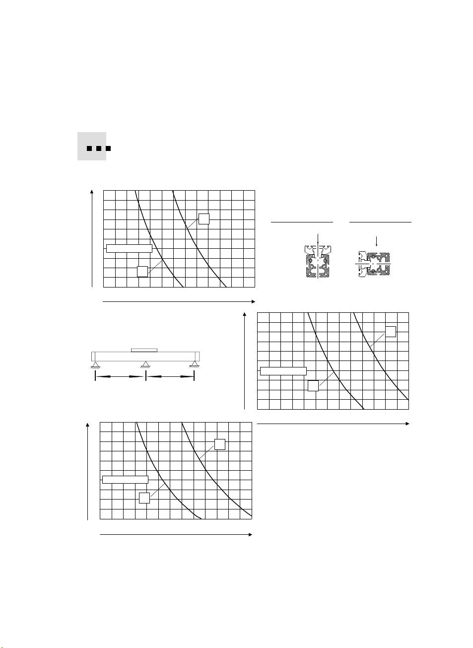
FDG−...−ZR−RF
10
9
8
F[kg]
7
6
5
4
FDG−25−ZR−RF
3
2
1
0
1200 1500 1800 2100 2400 2700
100
90
80
F[kg]
70
60
50
40
FDG−63−ZR−RF
30
20
10
0
1600 2800 3200 3600 40002000 2400
Vid enheter med långa slaglängder:
S Använd mittstöd MUP−... .
I Bild 6 visas de stödavstånd som krävs.
x
y
L[mm]
LL
x
y
L[mm]
Monteringslägex
Monteringslägey
F
3000
25
22,5
F[kg]
20
17,5
15
12,5
10
FDG−40−ZR−RF
7,5
5
2,5
0
1200 1500 1800 2100 2400 2700 3000
y
Bild6:
Nödvändiga stödavstånd L för
FDG−...−ZR−RF beroende på
monteringsläge, nominell storlek
och arbetslast F
F
x
L[mm]
Festo FDG−...−ZR−RF 0404NH Svenska
67
Page 68
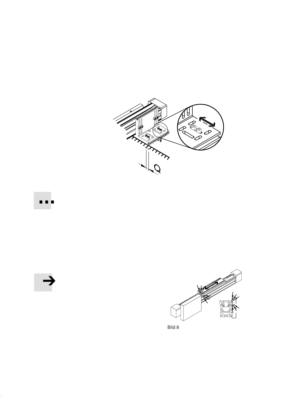
FDG−...−ZR−RF
УУУУУ
УУУУУ
УУУУУ
S Fäst byggsatsen för axelinfästning eller mittstöd på FDG−...−ZR−RF enligt
följande bild:
Bild7: Q = Spel för diagonal montering
Spårmuttrar kan om nödvändigt tjäna som fästanordningar i profilspåren.
Vid användning av FDG−...−ZR−RF tillsammans med drivaxel DGE−... eller DGP(L)−...:
S Använd drivaxelns stödavstånd även för FDG−...−ZR−RF.
På så sätt undviker du förspänning på grund av ojämn nedböjning.
68
S Skruva bara in fästskruvarna för
radiell justering löst till en början
(se Bild 7: Q).
På så sätt kan FDG−...−ZR−RF lätt justeras under vidare montering.
Vid montering av fästelementen:
S Se till att
byggsatsen för axelinfästning resp.
mittstöden befinner sig utanför
åkvagnens kollisionsområde genom att
skjuta åkvagnen en gång över hela
rörelsesträckan.
Bild8
Festo FDG−...−ZR−RF 0404NH Svenska
Page 69

FDG−...−ZR−RF
d
Vid användning av FDG−...−ZR−RF tillsammans med drivaxel DGE−... eller DGP(L)−...:
1. Se till att båda axlarnas åkvagnsrytorna
ligger på samma höjd inom hela
slagområdet.
2. Placera FDG−...−ZR−RF exakt parallellt med
drivaxeln.
3. Montera tandemplattan (se Bild 2) och
arbetslasten på åkvagnarna på
FDG−...−ZR−RF och drivaxeln på följande
sätt:
Tippmomentet av kraft F parallellt med
cylinderaxeln och avståndet d förblir
Därvid innefattar kraft F även
lågt.
tröghetskraft F = m ⋅ a, viktens kraft
och eventuella externa krafter.
Belastningar överskrider inte tillåtna
värden (se Tekniska data).
4. Skjut tandemplattan över hela slaglängden från ett ändläge till det andra.
Då positioneras slavstyrningen utan förspänning i förhållande till drivaxeln.
5. Dra åt fästskruvarna (se Bild 7: Q) på slavstyrningen.
Bild9
Bild10
F
d
F
Kontrollera om det krävs ytterligare externa stötdämpare eller anslag.
För att avläsa åkvagnspositionerna:
S Använd sensorer med induktiv kopplingsprincip i kombination med ferritisk
givarkam.
S Fullfölj monteringen av givarna enligt bruksanvisningen för givare och drivaxel.
Oanvända givarspår skyddar du bäst med hjälp av täcklister enligt kapitlet
Tillbehör.
Festo FDG−...−ZR−RF 0404NH Svenska
69
Page 70

FDG−...−ZR−RF
7 Idrifttagning, manövrering och drift
Varning
S Säkerställ inom enhetens rörelseområde:
att ingen sticker in händer i rörliga
delars rörelsefält (t.ex. genom
skyddsgaller)
att inga främmande föremål
förekommer.
Först när massan står helt stilla får det
vara möjligt att nå FDG−...−ZR−RF.
Notera
Främmande föremål (t.ex. muttrar eller skruvar) kan av misstag hamna i
urfräsningarna i gavlarna och falla ut.
Bild11
Varning
Föremål som har fallit ut genom gavlarna
kan skada personer och andra föremål.
S Säkerställ att personer eller föremål inte
Bild12
kan träffas av främmande föremål i
närheten av FDG−...−ZR−RF (t.ex. genom
skyddsgaller).
S Aktivera först drivmotorn med låga varvtal
2000
3000
och moment.
Då kör löparen först igenom hela
rörelsesträckan långsamt.
Bild13
70
1000
0
Festo FDG−...−ZR−RF 0404NH Svenska
U
min
Page 71
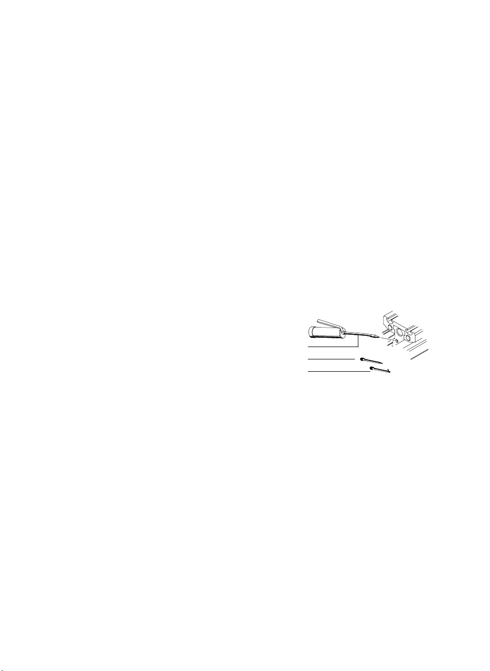
FDG−...−ZR−RF
8 Underhåll och skötsel
S Rekommendation:
Lämna in enheten till Festo för inspektion med ett intervall på
10000löpkilometer.
S Låt de skruvar och gängstift som inte uttryckligen behandlas i denna
bruksanvisning vara.
För smörjning av rullagerstyrningen:
S Intervall: vid behov (teoretisk värde: efter 10 000 km)
S Observera att smörjintervallerna måste kortas i följande fall
i miljöer med damm och smuts,
vid mycket korta arbetsslag (inkörning till en position).
S Olja in FDG−...−ZR−RF via smörjnipplarna
på åkvagnens båda gavlar.
Olja: t.ex. Constant OY 390 från Klüber i
München, Tyskland.
Smörjpistol: se Tillbehör.
För små monteringsutrymmen:
S Använd munstycksrör B (öppning axial)
eller C (öppning radial) istället för
standardmunstycksrör A.
S Kör därefter det nominella slaget fullständigt en gång
jämnt inuti FDG−...−ZR−RF.
A
B
C
Bild14
så att oljan fördelas
Vid varje underhållsåtgärd:
S Kontrollera om åkvagnen är glapp− och förspänningsfritt justerad.
Se kapitlet Åtgärdande av fel om du upptäcker något som inte stämmer.
9 Reparation
Vid störningar i driftförloppet:
S Se till att översyn av FDG−...−ZR−RF endast utförs av vår reparationsservice
(t.ex. vid glapp mellan åkvagn och skenstyrning).
Därmed undviks skador på axeln längre fram i tiden. Reparationen kräver
mycket exakta inställningsarbeten.
Festo FDG−...−ZR−RF 0404NH Svenska
71
Page 72

FDG−...−ZR−RF
10 Tillbehör
Typ Beteckning
MUP−... Mittstöd
HP−... Fotfäste
HMAV−... Adapterbyggsats HMP−...
HMSV−... Adapterbyggsats SLT−...
HMVA−... Gaveladapterbyggsats
HMVD−... Tandemplatta
HMVG−... Förbindningssbyggsats (för axelavstånd Ţ 200 mm)
HMVJ−... Justeringsbyggsats
HMVK−... Kryssadapter
HMVS−... Tandemstöd
HMVT−... Tandembyggsats
HMVV−... Avlastningsbyggsats
SIEN−... Givare med slutande eller brytande funktion
HWS−... Givarfäste
SF−... Givarkam
SIM−... Förlängningskabel
ZBH−... Centreringshylsor
NST/NSTL−... Spårmuttrar
ABP−... Täcklist
647 958
647 959
647 960
Bild15
72
Smörjpistol
Munstycksrör (öppning axial)
Munstycksrör (öppning radial)
Festo FDG−...−ZR−RF 0404NH Svenska
Page 73

FDG−...−ZR−RF
11 Åtgärdande av fel
Fel Orsak Åtgärd
Onormala ljud och
åkvagnen går trögt
Rödbrunt färgad
skenstyrning
Kännbart åkvagnsglapp Slitage, skada Lämna in enheten till Festo
En tandemanordning nära
ändläget går trögt
Fasthakning" i en position lång stilleståndstid Försvinner efter en
Vibrationer Axeln överbelastad Följ belastningsmaxvärden
Avsaknad av eller
feldefinierade
givarfunktioner
Bristfällig smörjning av
åkvagnslagring
Rost på grund av bristfällig
smörjning
Bristfällig parallellitet
mellan drivaxel och
FDG−...−ZR−RF
För hög dynamik Kontrollera
Felplacering av
arbetslastens tyngdpunkt
Extern inkoppling på
stativet eller i
fleraxelsystemet
Cylindergivare eller kabel
defekt
Montering av givarfäste
eller givarkam felaktig
Olja in eller lämna in till
Festo vid behov
Justera axlarna på nytt
inkörningsperiod
projekteringsförändringar
Ändra tyngdpunkt
Avlägsna inkoppling
Byt ut den defekta delen
Korrigera monteringen
Festo FDG−...−ZR−RF 0404NH Svenska
Kopplingsavstånd felaktigt
inställt
Felaktig brytare eller
anslutning
Justera
Byt ut den felaktiga delen
73
Page 74

FDG−...−ZR−RF
12 Tekniska data
FDG−25−ZR−RF FDG−40−ZR−RF
Konstruktion Passiv slavstyrning med rullagerstyrning
Temperatur 0 ... + 60 °C (lagring/drift)
Monteringsläge Valfritt
Åkvagnshastighet max 10 m/s
Tillåten arbetslast
Horisontellt
Vertikalt
Tillåten radiell kraft
FY, F
Z
Tillåten momentbelastning: (värden inom parentes gäller för GV−variant)
Mx [Nm]
My [Nm]
Mz [Nm]
max
)
|My|
My
max
|Mx|
Mx
10 kg
5 kg
150 N 300 N 600 N
7
15 (30)
15 (30)
max
)
Fy
|Fy|
max
)
|Mz|
Mz
)
25 kg
12,5 kg
18
60 (120)
90 (180)
|Fz|
Fz
max
v 1
Mz
FDG−63−ZR−RF
50 kg
25 kg
65
170 (340)
300 (600)
Fz
Mx
Fx
Material
Åkvagn, cylinderrör, cylindergavel: aluminium
Hjul, skruvar, spårmuttrar: stål
Anslag, avstrykare: gummi, filt
Skydd för löparen i spåret: IXEF
Ledstänger: stål
74
Festo FDG−...−ZR−RF 0404NH Svenska
Fy
My
Page 75

FDG−...−ZR−RF
Festo FDG−...−ZR−RF 0404NH
75
Page 76

FDG−...−ZR−RF
Weitergabe sowie Vervielfältigung dieses Dokuments,
Verwertung und Mitteilung seines Inhalts sind verboten,
soweit nicht ausdrücklich gestattet. Zuwiderhandlungen
verpflichten zu Schadenersatz. Alle Rechte sind für den Fall
der Patent−, Gebrauchsmuster oder Geschmacksmuster−
eintragung vorbehalten.
The reproduction, distribution and utilization of this
document as well as the comunication of its contents to
others without express authorization is
prohibited.
Offenders will be held liable for the payment of damages. All
rights reserved in the event of the grant of a patent, utility
module or design.
Sin nuestra expresa autorización, queda terminantemente
prohibida la reproducción total o parcial de este documento,
así como su uso indebido y/o exhibición o comunicación a
terceros. De
los infractores se exigirá el correspondie n t e
resarcimi e n t o de daños y perjuicios. Quedan reservados todos
los derechos inherentes, en especial los de patentes, de
modelos registrado s y estéticos.
Toute communication ou reproduction de ce document, sous
quelque forme que ce soit, et toute exploitation ou
communication de son contenu sont interdites, sauf
autorisation écrite
expresse. Tout manquement à cette règle
est illicite et expose son auteur au versement de dommages et
intérêts. Tous droits réservés pour le cas de la délivrance d’un
brevet, d’un modèle d’utilité ou d’un modèle de présentation.
È vietato consegnare a terzi o riprodurre questo documento,
utilizzarne il contenuto o renderlo comunque noto a terzi senza
esplicita autorizzazione. Ogni infrazione comporta il
riscarimento dei danni subiti. Sono riservati tutti i diritti
deriva nt i dalla concessione di brevetti per invenzioni industriali
di utilità o di brevetti per modelli ornamentali.
Detta dokument får inte utan vårt tillstånd utlämnas till
obehöriga eller kopieras, ej heller får dess innehåll delges
obehöriga eller utnyttjas. Överträdelse medför skade−
ståndskrav. Alla rättigheter förbehålls, särskilt rätten att
inlämna patent−, bruksmönster− eller mönsteransökningar.
Copyright:
EFesto AG&Co. KG,
Postfach
D−73726 Esslingen
Phone:
+49/711/347− 0
Fax:
+49/711 /347− 2144
e−mail:
service_intern ationa l@f esto .com
Internet:
http://www.festo.com
Original: de
Version: 0404NH
76
Festo FDG−...−ZR−RF 0404NH
 Loading...