

Page 1

EHPS
Parallel gripper
Instructions| Operating
8083687
8083687
2018-06
[8083689]
Page 2

Translation of the original instructions
2 Festo — EHPS — 2018-06
Page 3

Table of contents
1 About this document................................................................................................... 4
1.1 Further applicable documents...................................................................................... 4
1.2 Product labelling.......................................................................................................... 4
2 Safety........................................................................................................................... 4
2.1 Safety instructions........................................................................................................ 4
2.2 Intended use................................................................................................................ 4
2.3 Training of specialised personnel................................................................................. 4
3 Additional information................................................................................................ 4
4 Service..........................................................................................................................4
5 Product overview......................................................................................................... 5
5.1 Function....................................................................................................................... 5
5.2 Design........................................................................................................................... 6
6 Mounting..................................................................................................................... 6
6.1 Preparing the gripper fingers........................................................................................ 6
6.2 Mounting the gripper fingers........................................................................................ 7
6.3 Mounting the gripper.................................................................................................... 8
6.4 Mounting accessories................................................................................................... 9
7 Installation.................................................................................................................. 9
7.1 Electrical installation.................................................................................................... 9
8 Commissioning............................................................................................................ 11
8.1 Preparation................................................................................................................... 11
8.2 Execution...................................................................................................................... 11
9 Maintenance................................................................................................................ 12
9.1 Safety............................................................................................................................ 12
9.2 Cleaning....................................................................................................................... 12
9.3 Lubrication................................................................................................................... 13
10 Malfunctions............................................................................................................... 13
10.1 Diagnostics................................................................................................................... 13
10.2 Fault clearance............................................................................................................. 14
10.3 Repair............................................................................................................................15
11 Disassembly................................................................................................................ 16
12 Disposal........................................................................................................................16
13 Technical data............................................................................................................. 16
13.1 Technical data, general................................................................................................. 16
13.2 Characteristic curves.................................................................................................... 18
3Festo — EHPS — 2018-06
Page 4

About this document
1 About this document
1.1 Further applicable documents
All available documents for the product èwww.festo.com/pk.
1.2 Product labelling
Warning symbols on the product
Symbol Meaning
General warning indicator:
The symbol means a hazardous area and that the operating instructions must be read
and observed.
Tab. 1 Warning symbols on the product
2 Safety
2.1 Safety instructions
– Observe labelling on the product.
– Prior to assembly, installation and maintenance work: Switch off power supply, ensure that it is
off and secure it against being switched back on.
– Store the product in a cool, dry, UV-protected and corrosion-protected environment. Ensure that
storage times are kept to a minimum.
– Observe tightening torques. Unless otherwise specified, the tolerance is±20%.
– The occurrence of a failure could lead to unforeseeable movements if the gripper is connected
with the power supply. Only operate the gripper once protective measures have been taken
against mechanical threats to body parts.
2.2 Intended use
The intended use of the product is to grip and hold payloads (workpieces) using custom-designed
gripper fingers attached by the customer.
The gripper fingers are not included in the delivery.
When not used as intended, the product-supported protection can be impaired.
2.3 Training of specialised personnel
Installation, commissioning, maintenance and disassembly should only be conducted by qualified personnel.
The qualified personnel must be familiar with installation of electrical control systems.
3 Additional information
– Accessories èwww.festo.com/catalogue.
4 Service
Contact your regional Festo contact person if you have technical questions èwww.festo.com.
Festo — EHPS — 2018-064
Page 5

Product overview
5 Product overview
5.1 Function
The gripper has an integrated motor. The gripper mechanism converts the rotary motion of the motor
into a linear motion of the gripper jaws.
The gripper jaws move towards one another (closing) or apart (opening). Gripper fingers are fastened
to the gripper jaws.
The payload can be gripped in 2 ways:
– on the external contour (external gripping) when closing
– on the internal contour (internal gripping) when opening
The parallel gripper is controlled by a higher-order controller using digital signals.
5Festo — EHPS — 2018-06
Page 6
Mounting
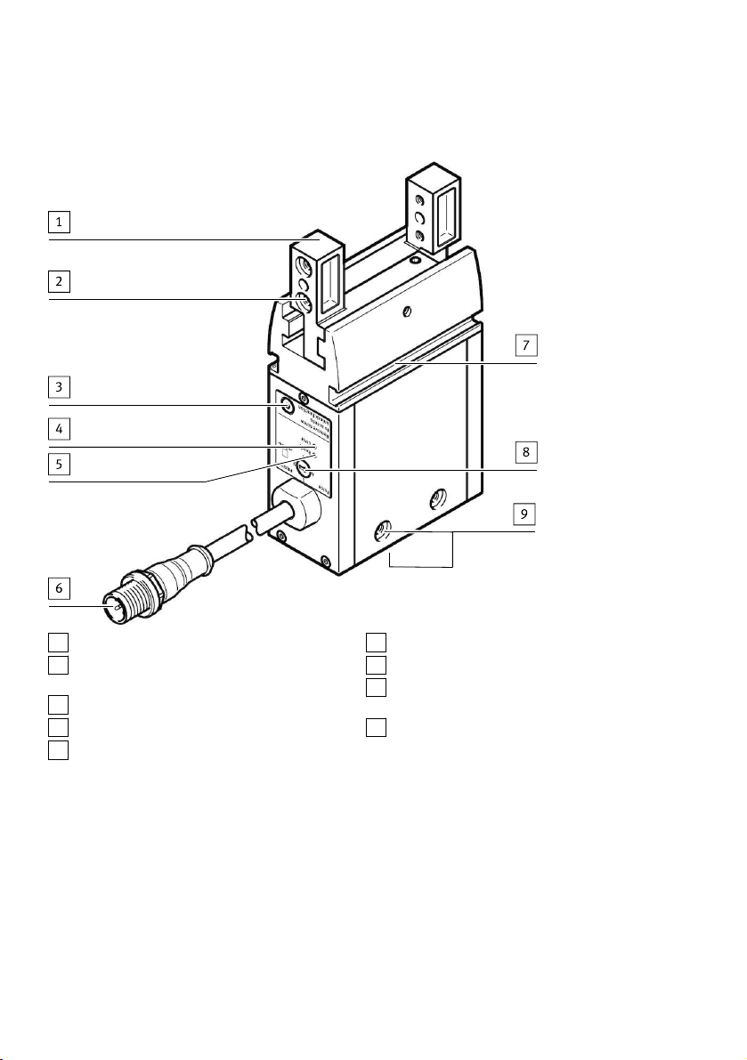
5.2 Design
1
Gripper jaws
2
Locating hole and thread for gripper finger
mounting
3
Plug screw
4
LED indicator (Error)
5
LED indicator (Ready)
Fig. 1 Product design
6
Electrical connection
7
Slot for proximity sensor
8
Rotary switch for adjusting the gripping
force
9
Locating hole and thread for mounting
6 Mounting
6.1 Preparing the gripper fingers
Requirements for gripper fingers:
– Observe maximum permitted forces and torques on the gripper jaws è 13 Technical data.
– Use gripper fingers that are as short and lightweight as possible.
– Observe maximum length and weight è 13 Technical data.
– Produce gripper fingers that are suitable for the payload and type of gripping action.
6 Festo — EHPS — 2018-06
Page 7

Mounting
6.2 Mounting the gripper fingers
A
Gripper finger
B
Centring pin
C
Screw
Fig. 2 Gripper finger mounting
1. Press centring pin or centring sleeve into locating holes in the gripper jaws.
2. Position the prepared gripper fingers on the gripper jaws and secure with 2 screws on each. Fix
gripper jaws in place during mounting and comply with tightening torque.
Size 16 20 25
Screw M4 M4 M5
Centring hole for cent-
[mm] 7 7 9
ring sleeve [H8]
Centring hole for cent-
[mm] 3 4 4
ring pin [H8]
Jaw width [mm] 10 ±0.05 12 ±0.05 15 ±0.05
Tightening torque
1) Brace at gripper jaws
1)
[Nm] 2.9 2.9 6
Tab. 2 Gripper finger mounting, dimensions and tightening torque
7Festo — EHPS — 2018-06
Page 8

Ready
Error
Force
Remove screw
to access
unlock function
1
2
3
4
Mounting
6.3 Mounting the gripper
Through-hole mounting and direct mounting
Fig. 3 Through-hole mounting on the side, direct mounting underneath (also possible on the side)
Mounting with adapter kit
Adapter kits èwww.festo.com/catalogue.
Fig. 4 Mounting with adapter kit from underneath
8 Festo — EHPS — 2018-06
Page 9

Installation
NOTICE!
Accumulation of heat results from cramped installation situation.
Material damage or malfunction.
• Mount the product with sufficient space for heat dissipation.
1. Press 2 centring sleeves into the locating holes of the gripper.
2. Use the centring sleeves to position the gripper on the connecting surface.
3. Select screws in accordance with the type of mounting.
4. Tighten screws with the associated tightening torque.
Size 16 20 25
Direct mounting
Screw M4 M4 M6
Max. screw-in depth [mm] 8 8 12
Centring hole [mm] 7 7 9
Tightening torque [Nm] 2.9 2.9 10
Through-hole mounting
Screw M3 M3 M4
Centring hole [mm] 7 7 9
Tightening torque [Nm] 1.2 1.2 2.9
Tab. 3 Mounting attachments and tightening torque
6.4 Mounting accessories
If required: use proximity sensor to sense the position of the gripper jaws in the slot7.
Use only proximity sensors approved for the product.
7 Installation
7.1 Electrical installation
WARNING!
Risk of injury due to electric shock
• For the electric power supply, use only PELV or SELV circuits that ensure a reliable electric disconnection from the mains network.
WARNING!
Risk of injury due to electric shock or burns.
The gripper does not offer any additional protection against unintended high currents in the supply
cables.
• The cross section of the supply cables should be designed to meet the maximum current value
that could occur in the event of a failure.
9Festo — EHPS — 2018-06
Page 10
Installation
WARNING!
Danger of crushing.
The gripper fingers could move unintentionally and crush body parts.
• Do not reach into the movement range.
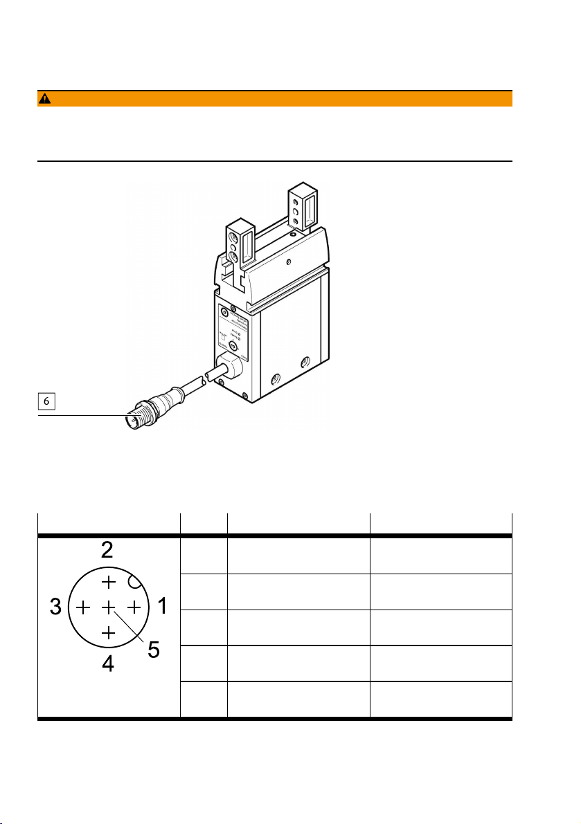
Fig. 5 Electrical connection
1. Switch off power to the controller and safeguard it from being switched on again unintentionally.
2. Use permissible connecting cable èwww.festo.com/catalogue.
3. Connect parallel gripper at the connection6 to the controller.
M12 plug (5-pin, A-coded) Pin
1)
Connection Designation
1 (BN)
+24VDC (±10%) Nominal operating voltage
brown
2 (WH)
Input 1 Open gripper jaws
white
3 (BU)
0V
–
blue
4 (BK)
Input 2 Close gripper jaws
black
5 (GY)
n.c. Not connected
grey
1)
Wire colour with use of connecting cables according to accessories èwww.festo.com/catalogue
Tab. 4 Pin allocation
10 Festo — EHPS — 2018-06
Page 11

Commissioning
8 Commissioning
8.1 Preparation
Setting the gripping force
8
Rotary switch for gripping force
Fig. 6 Setting the gripping force
• Set the required gripping force using the rotary switch 3.
– Position 1 = 50% of gripping force
– Position 2 = 70% of gripping force
– Position 3 = 85% of gripping force
– Position 4 = 100% of gripping force
8.2 Execution
WARNING!
Danger of crushing.
The gripper fingers could move unintentionally and crush body parts.
• Do not reach into the movement range.
Activation (opening/closing) of the gripper is via commands from a higher-order controller to the digital inputs (Pin2 and Pin4). In this case, the gripper is edge-triggered and moves on detection of a positive edge. As soon as a high signal level is detected, travel to the stop is executed. Please ensure that,
once travel is complete, the corresponding signal is reset again before transmitting a signal in the
opposite direction. Pause times of at least 10ms must be observed between cancelling the signal and
the next command.
11Festo — EHPS — 2018-06
Page 12

Maintenance
If a signal remains at the high signal level until the next travel, this can prevent unintended travel
being initiated in the event of a cable break.
Fig. 7
1. Switch on the power supply.
The "Ready" LED lights up green.
Ä
2. Opening the gripper jaws:
– Apply a rising edge (0è1) at Pin2 and
– 0 signal at Pin4.
Pin allocation for connection6 è Tab. 4 Pin allocation
3. Approach the workpiece to be gripped.
4. Closing the gripper jaws:
– Apply a rising edge (0è1) at Pin4 and
– 0 signal at Pin2.
5. Execute a test run. During the test, check that the workpiece is gripped properly.
9 Maintenance
9.1 Safety
WARNING!
Danger of crushing due to unexpectedly fast-moving loads and unintentional movements.
• Remove the payload.
• Switch off power to the product.
• Safeguard the power supply from being switched on again unintentionally.
9.2 Cleaning
• Clean the outside of the product with a soft cloth. Do not use aggressive cleaning agents.
12 Festo — EHPS — 2018-06
Page 13

Malfunctions
9.3 Lubrication
Interval Maintenance work
After 5 million switching cycles Grease the guide of the gripper jaws. Permissible
lubricating grease èwww.festo.com/spareparts.
Tab. 5
Cut the lubrication interval by half if one of the following applies:
• High thermal stress
• Heavy contamination
• Proximity of grease-dissolving liquids or vapours
10 Malfunctions
10.1 Diagnostics
LED Meaning
"Ready" LED
lights up green
"Ready" LED does
not light up
"Error" LED lights
up red
"Error" LED
flashes red
Tab. 6 LED indicator
Nominal operating voltage at connection 3 Pin1is 24VDC±10%.
Nominal operating voltage is switched off.
Nominal operating voltage at connection 3 Pin1 is outside the valid
range.
Device error
13Festo — EHPS — 2018-06
Page 14

Malfunctions
10.2 Fault clearance
WARNING!
Danger of crushing due to unexpectedly fast-moving loads and unintentional movements.
• Remove the payload.
• Switch off power to the product.
• Safeguard the power supply from being switched on again unintentionally.
WARNING!
Danger of crushing.
The gripper fingers could move unintentionally and crush body parts.
• Do not reach into the movement range.
Fault description Cause Remedy
Gripper does not hold payload
firmly.
formly.
Gripper fingers do not
open/close.
Squeaking noises
Tab. 7
Gripping point of gripper fingers
Move gripping point inwards.
is too far outwards.
Sufficient force cannot be
applied.
Increase travel path. Minimum
travelè 13 Technical data.
Payload is too heavy. Select a larger gripper.
Slots are dirty. Clean and grease the slots.Gripper fingers do not move uni-
Gripper jaws are distorted. Rectify distortion.
Jamming due to excessive
speed of the gripper fingers
Resolve jamming
è Resolve mechanical jamming
of gripper jaws.
Connection interruption
Check connecting cable.
between gripper and activation
Gripper is faulty. Replace gripper.
Lack of lubrication Lubricate gripper
è 9.3 Lubrication.
Payload is too great. Observe permissible values
è 13 Technical data.
14 Festo — EHPS — 2018-06
Page 15

Malfunctions
Resolve mechanical jamming of gripper jaws
3
Plug screw
Fig. 8 Resolve jamming of gripper jaws
1. Remove the plug screw.
2. Rotate the worm shaft underneath using the hex wrench until the jamming is resolved:
– Anti-clockwise (external gripping)
– Clockwise (internal gripping)
3. Retighten plug screw è Tab. 8.
Size 16 20 25
Hex wrench ß1.5 ß1.5 ß2
Tightening torque for
plug screw
Tab. 8
[Nm] 0.6 0.6 2.8
10.3 Repair
Send product to the Festo repair service for repair.
15Festo — EHPS — 2018-06
Page 16

Disassembly
11 Disassembly
WARNING!
Danger of crushing due to unexpectedly fast-moving loads and unintentional movements.
• Remove the payload.
• Switch off power to the product.
• Safeguard the power supply from being switched on again unintentionally.
12 Disposal
ENVIRONMENT!
Send the packaging and product for environmentally sound recycling in accordance with the current
regulations èwww.festo.com/sp.
13 Technical data
13.1 Technical data, general
Size 16 20 25
Design Electric parallel gripper
Mounting position Any
Minimum travel [mm] 0.5
Mass moment of inertia [kg
Max. load per gripper
finger
Max. permissible
length of gripper finger
Repetition accuracy [mm] £0.03 £0.01 £0.01
Max. interchangeability [mm] £0.02
Nominal operating
voltageDC
Max. current consumption
Switching level [V] +18…+28 (1 signal)
Max. cable length [m] 30 (including gripper cable)
Degree of protection IP40
Relative humidity [%] 0…95 (at 25C non-condensing)
0.78 2.02 5.24
cm²]
[g] 100 150 230
[mm] 80 100 120
[VDC] 24±10%
[A] 1 2
–3…+8 (0 signal)
16 Festo — EHPS — 2018-06
Page 17

Technical data
Size 16 20 25
Ambient
temperature
1)
[°C] +5…+60
Storage temperature [°C] –20…+60
CE marking (declaration of conformity)
To EU EMC Directive2)
In accordance with EU RoHS Directive
3)
Electrical safety In accordance with standard EN 61010-1:2010
Weight [g] 296 532 904
Materials
Housing Aluminium
Cover Polymer
Gripper jaws, bearings,
Steel
plugs, screws
O-ring NBR
Max. force (static) and max. torque (static)
F
Z
M
X
M
Y
M
Z
1) Max. housing temperature = ambient temperature +35K
2) Only when using the connecting cable from Festo
3) Max. length of connecting cable (including gripper cable): 30m
[N] 200 325 450
[Nm] 7 13 28
[Nm] 4.4 8 16
[Nm] 7 13 28
Tab. 9 Technical data
17Festo — EHPS — 2018-06
Page 18

Technical data
13.2 Characteristic curves
Lever arm x
Vertical Horizontal
Tab. 10 Alignment of lever arm x
18 Festo — EHPS — 2018-06
Page 19

Technical data
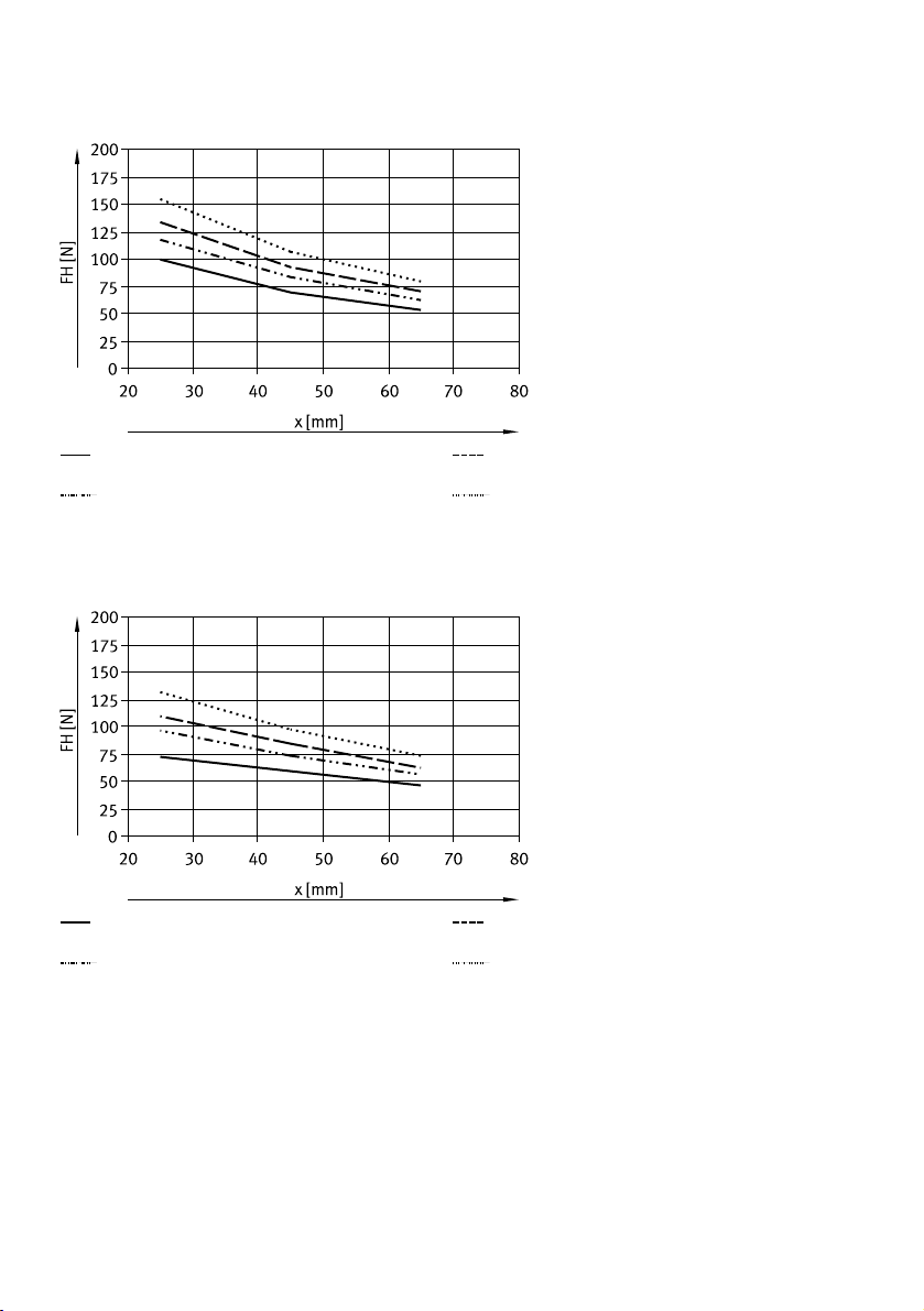
Gripping force FH as a function of lever arm x and rotary switch position è 8.1 Preparation.
Position 1
Position 2
Fig. 9 EHPS-16 external gripping, lever arm vertical
Position 1
Position 2
Fig. 10 EHPS-16 internal gripping, lever arm vertical
Position 3
Position 4
Position 3
Position 4
19Festo — EHPS — 2018-06
Page 20
Technical data
Position 1
Position 2
Fig. 11 EHPS-16 external gripping, lever arm horizontal
Position 1
Position 2
Fig. 12 EHPS-16 internal gripping, lever arm horizontal
Position 3
Position 4
Position 3
Position 4
20 Festo — EHPS — 2018-06
Page 21

Technical data
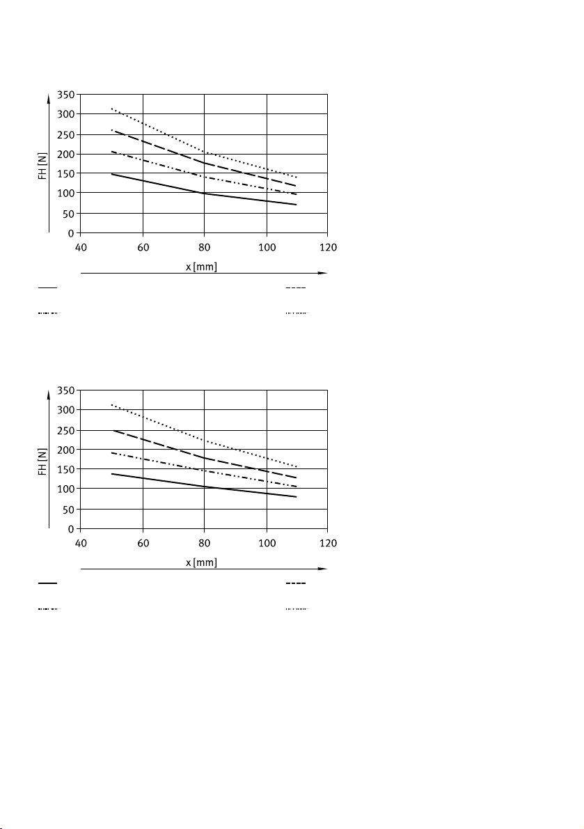
Position 1
Position 2
Fig. 13 EHPS-20 external gripping, lever arm vertical
Position 1
Position 2
Fig. 14 EHPS-20 internal gripping, lever arm vertical
Position 3
Position 4
Position 3
Position 4
21Festo — EHPS — 2018-06
Page 22

Technical data
Position 1
Position 2
Fig. 15 EHPS-20 external gripping, lever arm horizontal
Position 1
Position 2
Fig. 16 EHPS-20 internal gripping, lever arm horizontal
Position 3
Position 4
Position 3
Position 4
22 Festo — EHPS — 2018-06
Page 23

Technical data
Position 1
Position 2
Fig. 17 EHPS-25 external gripping, lever arm vertical
Position 1
Position 2
Fig. 18 EHPS-25 internal gripping, lever arm vertical
Position 3
Position 4
Position 3
Position 4
23Festo — EHPS — 2018-06
Page 24
Technical data
Position 1
Position 2
Fig. 19 EHPS-25 external gripping, lever arm horizontal
Position 1
Position 2
Fig. 20 EHPS-25 internal gripping, lever arm horizontal
Position 3
Position 4
Position 3
Position 4
24 Festo — EHPS — 2018-06
Page 25

Page 26

Reproduction, distribution or sale of this document or communication of its contents to others without express authorization is
prohibited. Offenders will be liable for damages. All rights
reserved in the event that a patent, utility model or design patent
is registered.
Copyright:
Festo AG & Co. KG
Ruiter Straße 82
73734 Esslingen
Germany
Phone:
+49 711 347-0
Fax:
+49 711 347-2144
e-mail:
service_international@festo.com
Internet:
www.festo.com
 Loading...