

Page 1
DRRD-...-PS1
3 Transport and storage
• Take into account the weight of the semi-rotary drive with intermediate-position
module.
Depending on the design, the DRRD-...-PS1 weights up to 20 kg.
• Transport the DRRD-...-PS1 by grasping the housing. Transporting it by grabbing
the dampeners 1 is not recommended, since the dampeners of the intermediate position can move axially (no safe stop).
Festo AG & Co. KG
Postfach
73726 Esslingen
Germany
+49 711 347-0
www.festo.com
Enclosure for operating instructions 8003697
1308NH
[8028343]
Original: de
Intermediate-position module DRRD-...-PS1 English........................
Note
• Observe the warnings and notes in the operating instructions for the DRRD
semi-rotary drive.
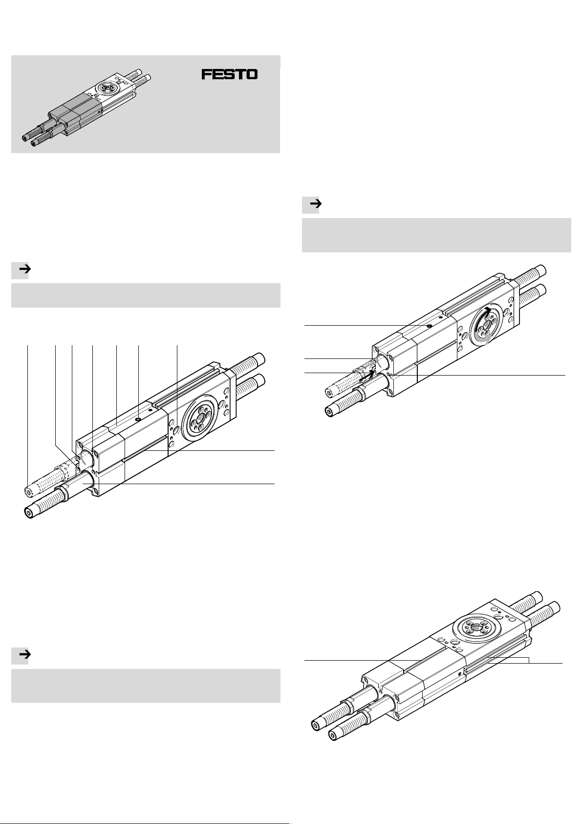
1 Control sections and connections
1 2 4 53 67
4 Installation
4.1 Installation, mechanical
• Secure the semi-rotary drive at the intended position and the effective load to
the drive flange ( Operating instructions DRRD).
4.2 Installation, pneumatic
• Connect tubes to the supply ports ( Fig. 2):
– intermediate position 4
– semi-rotary drive 2 (swivel clockwise)
– semi-rotary drive 3 (swivel anti-clockwise).
Note
Sucked-in contamination and fluids disturb the function.
– Keep venting hole 6 c lean and dry.
– Do not cover venting hole 6.
6
3
2
4
1 Shock absorbers or P-absorbers
secured with lock nut (2x)
2 Supply port for semi-rotary drive
(swivel clockwise)
3 Supply port for semi-rotary drive
(swivel anti-clockwise)
4 Compressed air supply port for
intermediate-position module
Fig. 1
2 Function and application
Note
The semi-rotary drive with intermediate-position module DRRD-...-PS1 can be
destroyed through incorrect use.
• Make sure that the intermediate-positionmodule is throttled.
5 Intermediate-position module
DRRD-...-PS1
6 Venting hole with filter
7 Fastening interface at semi-rotary
drive DRRD (2x)
8 Slot for cylinder switch (2x)
9 Sleeve for reception of the shock
absorber (2x)
8
9
Fig. 2
To set the swivel speed at the semi-rotary drive:
• Use one-way flow control valves in all supply ports:
– for DRRD-16/20 as close as possible to the supply ports
– for DRRD-25 … 50 screwed directly into the supply ports.
For vertical installation and eccentric loads:
• Use the controlled throttle check valves HGL or an air reservoir VZS.
In this way you can prevent the effective load from sliding down suddenly if
there is a sudden pressure drop.
4.3 Installation, electric
• Place the c ylinder switches in the slots aJ to interrogate the intermediate position directly at the semi-rotary drive. Slot 8 can be used to interrogate the
intermediate position piston.
8
aJ
The intermediate-position module DRRD-...-PS1 is intended to permit positioning
of the flanged shaft in half of the nominal rotation angle of the semi-rotary drive
DRRD. This intermediate position can be travelled through.
Fig. 3
Page 2

5 Commissioning
5.1 Adjustment of the intermediate position
Note
Without counter pressure, the connection between the sleeve and the screw-in
connector inside the intermediate-position module can loosen. This can result in
failure to function.
• Turn the lock nut or dampener only with simultaneous counter pressure on the
spanner flat of the sleeve 9.
• Check the setting dimension of the two dampeners 1:
– setting dimension X1 and X2 are the same size
(dimension Y = 0 Fig. 5, delivery status)
– setting dimensionlies between X
min
and X
( Fig. 6).
max
• If necessary, adjust the intermediate position as follows:
1. Loosen the lock nuts on both dampeners 1.
2. Turn the dampener 1 until the desired intermediate position is reached. When
doing this, hold the sleeve 9. The setting dimension must lie between X
X
( Fig. 6).
max
min
and
9
Size 16 20 25 32 35 40 50
Setting dimension X (P-cushioning)
Xmin [mm] 7.7 14 .9 14.2 12.5 –
Xmax [mm] 10.1 17.8 20.6 23.2 –
Setting dimension X (Y9-cushioning)
Xmin [mm] 29.6 41.8 56.9 70.3 88.6 86.7 114
Xmax [mm] 32 44.5 60.4 78.5 96.2 92.7 128
Anglechangeperrevolution
at th e dampener
Dimension Y for 10° swivel
angle change
Lock nut
Spanner size [mm] 13 15 19 27 32 32 36
Tightening torque [Nm] 3 5 20 35 60 60 80
[°] 4.3 4.5 3.3 4.1 4.1 2.7 1.9
[mm] 2.3 2.4 3.2 3.7 3.7 5.6 8
Fig. 6
1
Fig. 4
3. Press the dampeners into the travelled-in end position until they meet resistance. The shaft of the semi-rotary drive thereby rotates into the intermediate
position.
Through the off-set mounting of the shock absorber (dimension Y), the mid-position (W=90°) can be adjusted by ±10°.
The following settings are possible ( Fig. 5 and Fig. 6).
Fig. 7 Entire setting range on the DRRD-...-PS1
4. Check the intermediate position under pressure.
5. Readjust the dampener, if required.
After the end of the settings:
Note
Without counter pressure, the connection between the sleeve and the screw-in
connector inside the intermediate-position module can loosen. This can result in
failure to function.
• Tighten the locking nuts again. Tightening torque ( Fig. 6).
To lock the hex nuts, the spanner flat of the sleeve or the internal hexagon
socket of the dampener must be counter held.
2
1
Fig. 8
Fig. 5
If the setting dimension Xmax is exceeded, the shock absorber does not cushion
correctly at the intermediate position.
If the setting dimension Xmin is fallen below, the shock absorber not only cushions the intermediate position, but also the end position of the semi-rotary
drive. The cushioning time of the end position might rise as a result. The cushioning time of the intermediate position is not affected by this.
5.2 Setting of the swivel speed
Note
• Observe the following relationship when setting the swivel speed:
– The flow control valves at the connections for rotation of the semi-rotary
drive affect the speed with which the intermediate position is travelled to.
Both directions can be adjusted separately from each other.
– The flow control valve at the connection for the intermediate position regu-
lates the speed with which the end position (from out of the intermediate
position) is travelled to. Both directions are hereby regulated simultaneously.
Page 3

• Select one of the activationalternatives:
Alternative 1
Circuit diagram (activation with 5/3-way valve and 3/2-way valve)
Control sequence
Alternative 3 (shortened s wivel time in 180°-operation in a swivel direction)
Circuit diagram (activation with 5/3-way valve and 3/2-way valve)
Control sequence
Fig. 9
Alternative 2
Circuit diagram (activation only with 3/2-way valves)
Control sequence
Fig. 11
5.3 Carrying out commissioning
War nin g
Danger of injury due to uncontrolled movement of the semi-rotary drive
(e.g. through extending dampener 1).
• Considerthat the pneumatic actuation of the semi-rotary drive can trigger a
movement in case of:
– eccentrically attached payload, due to the strong unbalance
– function variant Y9/Y12 due to the resetting force (back pressure) of the
shock absorber.
• When the intermediate position is exited, make sure that nobody/nothing is in
the movement area of the dampener.
• Start the test run at first with reduced operating pressure.
Fig. 10
The intermediate position may only be travelled to (valve V2) if the semi-rotary
drive is simultaneously exhausted. This ensures that t he flow control valves fulfil
their function and no accidental change in rotation angle takes place.
Fundamentally, an overswing may occur in the intermediate position. This can be
minimised through corresponding restriction of speeds (exhaust air flow control).
Note
Excessive loads can damage the DRRD-...-PS1.
• Make sure that the following values are not exceeded when swivelling into the
intermediate position:
– the maximum permissible mass moment of inertia ( 7 Technical data) and
the maximum permissible swivel time of the intermediate-position module
DRRD-...-PS1 ( www.festo.com/catalogue).
• Make sure that the following values are not exceeded while swivelling into the
end position:
– the maximum permissible mass moment of inertia of the semi-rotary drive
DRRD.
For the swivel motion from the intermediate position into the end positions,
the respective values of the corresponding function variants of the semirotary drive are permissible ( Technical data in the operating instructions
for the DRRD).
Page 4

1. Turn the upstream one-way flow control valve of the semi-rotary drive and intermediate position completely closed and open it back up one rotation.
2. Pressurize the system and the product.
3. Start a test run with low swivel frequency.
4. Turn all one-way flow control valves open one additional rotation until the desired speed of the end position and intermediate position is reached. This c an
bethecaseatdifferenttimes.
6Operation
Note
The intermediate-position module can be destroyed if it runs against an unpressurised chamber.
• Make sure that the chamber from the previous operating status is pressurized
at the semi-rotary drive. Only when the valves are reversed simultaneously is
an air cushion present in the chamber, which makes the function of the exhaust air flow control valve possible.
7Technicaldata
Size
Mass moment of inertia (swivelling into intermediate position)
P(min.) [kgcm2] 0 0 0 0 –
P(max.) [kgcm2] 150 300 400 500 –
Y9/Y12 (min.) [kgcm2] 15 40 100 100 500 1000 2000
Y9/Y12 (max.) [kgcm2] 500 900 1500 8000 15000 23000 40000
Max. perm. swivel time ( www.festo.com/catalogue)
Pneumatic port M5 G1/8
Operating pressure range
P [bar] 4…8 –
Y9/Y12 [bar] 2…10
Swivel angle
Intermediate position [°] 90 ±10
End positions [°] 0 … 80; 100 … 180
Materials
Housing, cover Anodised aluminium
Dampener, Steel, NBR
Sleeves Stainless steel
Weight (total load)
P [kg] 1.10 1.47 2.35 5.0 – – –
Y9 [kg] 1.12 1.53 2.41 5.28 8.51 10.52 19.12
16 20 25 32 35 40 50
Fig. 12
 Loading...