

Festo DRRD-32-P2E2, DRRD-16-P2E2, DRRD-35-P2E2, DRRD-40-P2E2, DRRD-63-P2E2 Operating Instructions Manual
...Page 1
DRRD-...-P..E..
Festo AG & Co. KG
Ruiter Straße 82
73734 Esslingen
Germany
+49 711 347-0
www.festo.com
Appendix to the operating instructions 8103851
2018-12a
[8103853]
Translation of the original instructions
Energy throughfeed DRRD-...-P..E.. English...............................
For all available product documentation è www.festo.com/pk
Note
Observe the warnings and instructions in the operating instructions for the
DRRD semi-rotary drive.
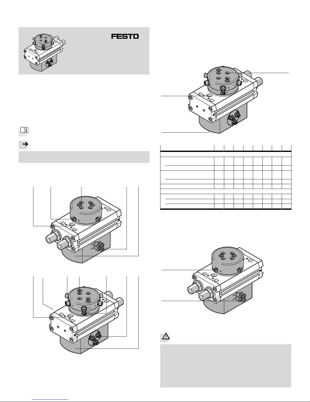
1 Control sections and connections
DRRD-...-P.. (pneumatic)
1 2 4 57
DRRD-...-P..E.. (pneumatic and electric)
1 234 65 7
1 Through-hole for mounting the
DRRD (2x)
2 Supply port P1 ... P8 (output)
3 Electrical output S1 ... S8 (socket)
4 Mounting interface for working
load (4x)
5 Supply port P1 ... P8 (input)
6 Electrical input S1 ... S8 (plug)
7 Housing
Fig. 1
2 Function and application
The energy throughfeed DRRD-...-P..E.. serves to permit the passage of com
pressed air and electrical signals through the drive shaft of the DRRD semi-rotary
drive.
3 Installation
3.1 Installation, mechanical
Affix the DRRD with two screws to holes 1 and with 2 centring sleeves to the
housing 7.
Affix the working load with at least two screws positioned opposite one another
to the drive flange, and with centring sleeves to threads 4.
Tightening torques are shown in the table below.
4
1
7
Fig. 2
Size 16 20 25 32 35 40 50 63
Mounting of DRRD
Screw in 1
(direct mounting)
M5 M5 M6 M8 M8 M10 M10 M12
Tightening torque [Nm] 6 6 10 18 18 30 30 55
Screw through 1
(through-fastening)
M4 M4 M5 M6 M6 M8 M8 M10
Tightening torque [Nm] 3 3 6 10 10 18 18 30
Centring sleeve ZBH [mm] 9 9 12 15 15 15 15 25
Mounting of working load
Screw in 4 M4 M4 M5 M6 M6 M6 M8 M10
Tightening torque [Nm] 3 3 6 10 10 10 20 40
Centring sleeve ZBH [mm] 7 7 9 9 9 9 12 15
Fig. 3
3.2 Installation, pneumatic
If using the energy throughfeed with pneumatic connections DRRD−...−P. . :
Connect tubes to pneumatic connections 2 and 5.
Corresponding port identifications are used to indicate which tube to fit to
which push-in fitting (tubing dimensions è Fig. 8).
2
5
Fig. 4
3.3 Installation, electric
Warning
Danger of short circuit! If one of the electrical inputs 6 is supplied with voltage,
there will be voltage at all electrical inputs, because the positive and negative
lines are connected together inside the component.
Ensure that the electrical inputs 6 share a common voltage source.
Otherwise the DRRD may be irreparably damaged by large compensating
currents.
Leave the cover caps on the unused plugs 6.
The plugs 6 on the side of the housing are not protected in any other way
against accidental contact.
Page 2
Note
Only use connection accessories with a straight plug
(Accessories è www.festo.com/catalogue) at electrical connections 3
and 6.
If using the energy throughfeed with electrical connections DRRD−...−P..E..:
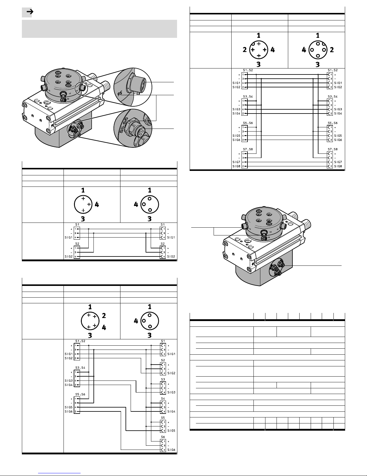
Connect lines to electrical connections 3 and 6.
Corresponding port identifications (A) are used to indicate which plug to plug
into which socket.
(A)
3
6
Fig. 5
Pin allocation DRRD-16/20-...-P2E2
1)
Electrical connection Input Output
Number of connections 2 (plug 6) 2 (sockets 3)
Designation (A) S1, S2 S1, S2
Circuit diagram
1) All contacts 1 (positive) connected with one another.
All contacts 3 (negative) connected with one another.
Pin allocation DRRD-25/32/35-...-P4E6
1)
Electrical connection Input Output
Number of connections 3 (plug 6) 6 (sockets 3)
Designation (A) S1;S2, S3;S4, S5;S6 S1, S2, S3, S4, S5, S6
Circuit diagram
1) All contacts 1 (positive) connected with one another.
All contacts 3 (negative) connected with one another.
Pin allocation DRRD-40/50/63-...-P8E8
1)
Electrical connection Input Output
Number of connections 4 (plug 6) 4 (sockets 3)
Designation (A) S1;S2, S3;S4, S5;S6, S7;S8 S1;S2, S3;S4, S5;S6, S7;S8
Circuit diagram
1) All contacts 1 (positive) connected with one another.
All contacts 3 (negative) connected with one another.
Fig. 6
In DRRD-...-P4E6, two electrical outputs 3 are assigned to each electrical out
put 6.
6
3
Fig. 7
4 Technical data
Size 16 20 25 32 35 40 50 63
Pneumatic specifications (DRRD-...-P..)
Number of pneumatic
connections
2 4 8
Tubing O.D. [mm] 4
Max. operating pressure [bar] 8
Flow rate per channel [l/min] 86 33
Electrical specifications (DRRD-...-P..E..)
Rated voltage [V] 30
Max. perm. current per sig
nal line
1)
[A] 1.5
Cable cross section [mm2] 0.14
Number of signal lines 2 6 8
Electrical connection M8 M12
Materials
Housing Anodised aluminium
Plug PA, CuZn, NBR, PU
Weight (energy throughfeed only)
P.. [kg] 0.32 0.35 0.71 0.92 1.09 1.47 1.95 2.25
P..E.. [kg] 0.46 0.48 0.72 0.90 0.88 1.77 2.33 2.61
1) The positive and negative lines of all electrical connections are connected together. The combined
maximum peak current for this common positive and negative line is likewise 1.5 A.
Fig. 8
 Loading...