

Page 1

en Operating
instructions
8081494
2018-01f
[8081496]
Fluidic Muscle
DMSP/MAS
Page 2

DMSP/MAS
2 Festo – DMSP/MAS – 2018-01f
Translation of the original instructions
Symbols: Installation and commissioning may only be per
formed in accordance with these instructions by
technicians with appropriate qualifications.
Warning
Caution
Note
Environment
Accessories
English 3.........................................................................
Page 3

DMSP/MAS
Festo – DMSP/MAS – 2018-01f English 3
English – Fluidic Muscle DMSP/MAS
Table of contents
1 Configuration 4............................................................
2 Safety 5..................................................................
2.1 Intended use 5.............................................................
2.2 General safety instructions 5..................................................
2.3 Qualified personnel 5........................................................
3 Function 6................................................................
4 Storage 6.................................................................
5 Installation 7..............................................................
5.1 Mechanical installation 7.....................................................
5.2 Pneumatic installation 8.....................................................
6 Commissioning 9...........................................................
6.1 Test run 9.................................................................
7 Operation 10...............................................................
8 Maintenance and care 11.....................................................
9 Disassembly and repair 11....................................................
10 Disposal 11................................................................
11 Accessories 11..............................................................
12 Fault clearance 12...........................................................
13 Technical data 13............................................................
14 Characteristic curves 14......................................................
Page 4

DMSP/MAS
4 Festo – DMSP/MAS – 2018-01f English
Documentation on the product
For all available product documentation è www.festo.com/pk
1 Configuration
DMSP MAS-…-K/O
1 342 5 647
1 Thread for supply port (only for DMSP)
2 Connecting thread (only for DMSP)
3 Connecting flange with press-form sleeve
(only for DMSP)
4 Contracting diaphragm (fibre-reinforced rub
ber tubing)
5 Thread for connecting adapter (only for
MAS-…-K/O)
– for MAS-…-MO open on both sides
– for MAS-…-MC open on one side
6 Force limiter inside the connecting flange
(only for MAS-…-K)
7 Connecting flange with external hexagon
(only for MAS-…-K/O)
Fig. 1
Page 5

DMSP/MAS
Festo – DMSP/MAS – 2018-01f English 5
2 Safety
2.1 Intended use
The fluidic muscle DMSP/MAS is intended for the following use:
– lifting and lowering of loads
– vibration and shaking applications
– transmission of force (e.g. clamping of two plates)
– use as pneumatic spring
The DMSP/MAS is a pure tensile actuator that has no internal guide. The tensile force is maximum at the
start of the contraction and then declines to zero with the stroke in a degressive manner. The expansion in
the peripheral direction cannot be used for clamping tasks, since the friction can cause damage to the dia
phragm.
The product is used for rough positioning of payloads in combination with tools or as a drive when ex
ternal guides are used.
The product is not approved for operating conditions in which vegetable and water-soluble greases or
oils can penetrate.
2.2 General safety instructions
Warning
People can be injured by the sudden release of pneumatic forces or catapulted compon
ents.
Take the great potential energy into account with all work on the pressurized
DMSP/MAS. A sudden release of this energy (e.g. through bursting of the contract
ing diaphragm due to incorrectly stressing it) can fling individual parts of the
DMSP/MAS with very great acceleration.
Take into consideration the legal regulations for the respective location.
Only use the product if it is in its original status and in an excellent technical status.
Use the product only within the defined values (è 13 Technical data and 14 Characteristic curves).
Do not make any unauthorised modifications to the product.
Take into consideration the ambient conditions at the location of use.
2.3 Qualified personnel
Only qualified personnel may perform installation, commissioning, maintenance and disassembly of the
product. The qualified personnel must be familiar with installation of pneumatic systems.
Page 6

DMSP/MAS
6 Festo – DMSP/MAS – 2018-01f English
3 Function
Through pressurisation, the contraction membrane3 of the DMSP/
MAS expands in the direction of the periphery. This creates tensile force
and a contraction motion in the longitudinal direction.
The DMSP/MAS is single-acting. Movement is transferred to the pay
load with the aid of connecting elements (è 11 Accessories), which
are screwed into thread 1. For the DMSP, the adapter is already integ
rated.
A force limiter is integrated into the connecting flange2 of the
MAS-…-K. If the limit of the force limiter is exceeded, a valve dis
charges the excess compressed air.
Fig. 2
4 Storage
Unfavourable storage conditions can impair operational reliability.
Ensure that the following points are complied with in storage:
– Do not store DMSP/MAS in a kinked condition
– Protect it from UV radiation (leave it in the protective sleeve until use)
– Store with low humidity (60%)
– Avoid high temperatures (max.+30°C)
Protect product in storage from damaging influences.
Damaging influences include:
– corrosive coolant or other materials (e.g. ozone)
– oils, greases and grease-solvent vapours
– glowing chips or sparks
Page 7
DMSP/MAS
Festo – DMSP/MAS – 2018-01f English 7
5 Installation
5.1 Mechanical installation
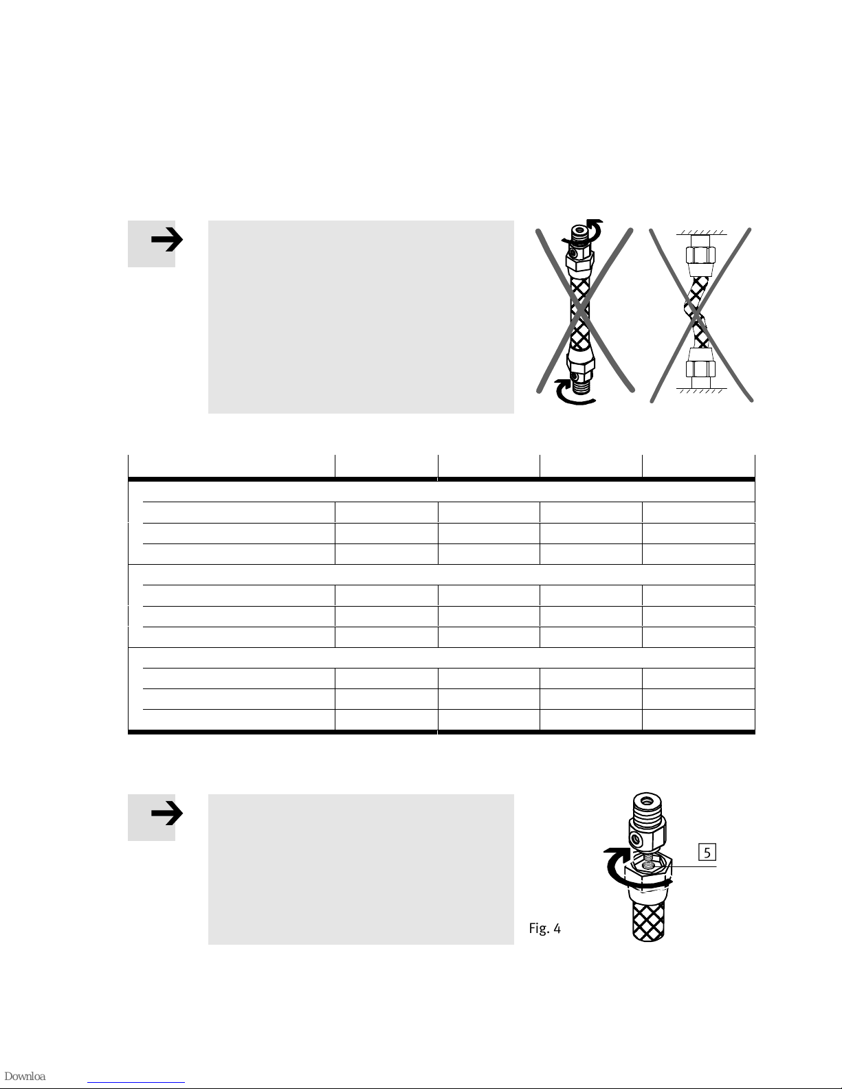
Note
Certain mechanical stresses on the contracting
membrane reduce the service life of the DMSP/
MAS.
Ensure that the membrane always
– remains free from torsion
– is mounted remains unkinked (uncom
pressed) even when unpressurized (no
folding)
DMSP 5
10 20 40
Connecting thread6
DMSP-…-AM M8 M16x1.5 M20x1.5 M30x1.5
DMSP-…-CF M4 – – –
DMSP-…-CM/-RM M6 M8 M10x1.25 M16x1.5
Recommended through-holes [H12]
DMSP-…-AM 8.4 mm 17 mm 21mm 31mm
DMSP-…-CF 4.3mm – – –
DMSP-…-CM/-RM 6.4 mm 8.4 mm 10.5 mm 17 mm
Max. tightening torque
1)
DMSP-…-AM 7…10 Nm 15…19 Nm 23…28 Nm 100…110 Nm
DMSP-…-CF 2,5…3 Nm – – –
DMSP-…-CM/-RM 4…6 Nm 7…10 Nm 12…16 Nm 50…55 Nm
1) Secured with Loctite 222 (DMSP-10) / Loctite 242 (DMSP-20/40)
Tab. 1
Note on MAS-10
If the thread on the MXAC connecting adapter is
too long, this can damage the connecting thread
of the MAS-10-…-O (without force limiter).
Make sure that the connecting thread
lengths of adapter and MAS fit each other
(è Tab. 2).
Fig. 3
Ó
Ó
Ó
Fig. 4
5
Page 8
DMSP/MAS
8 Festo – DMSP/MAS – 2018-01f English
1. Lightly grease the thread of the connecting adapter. This reduces the mounting forces.
2. Screw the connecting adapter (è11 Accessories) into the mounting thread of the MAS5.
MAS
10 20 40
Thread1
Open M10x1.25 M16x1.5 M20x1.5
Closed M10x1.25 M10x1.25 M16x1.5
Connecting thread length
MAS-…-MO-K 15 mm 24 mm 30 mm
MAS-…-MC-K 15 mm 15 mm 24 mm
MAS-…-MO-O 10 mm 26 mm 22 mm
MAS-…-MC-O 10 mm 15 mm 20 mm
Adapter thread length
MXAC- (old) 15 mm
1)
24 mm 30 mm
MXAD- (new) 10 mm 18 mm 20 mm
Max. permitted tightening
torque
8…13 Nm 15…25 Nm 35…45 Nm
1) If used with the old adapter MXAC-R10, the MAS-10-...-O-... (with force limiter) will be damaged.
Tab. 2
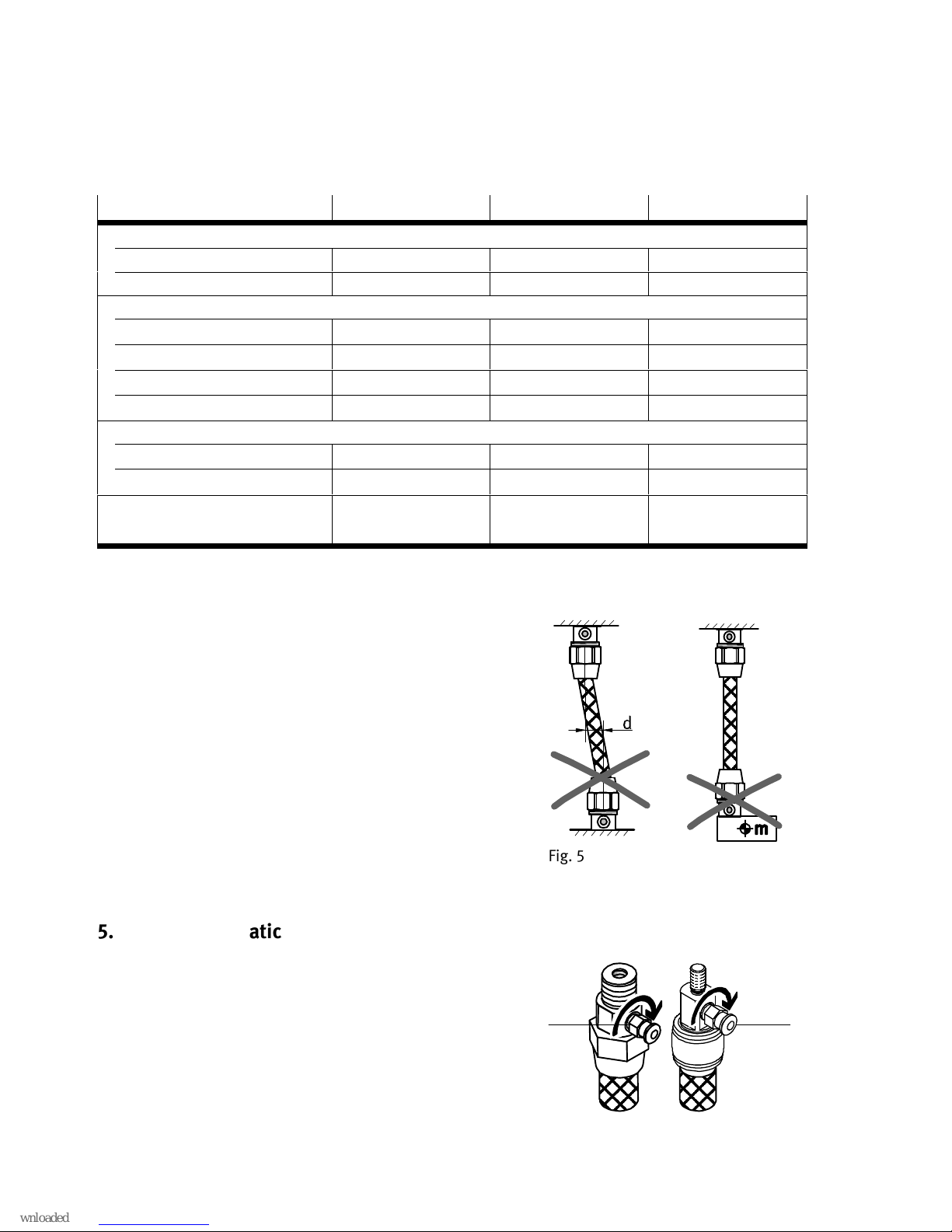
3. When placing the moveable mass, make sure that the fol
lowing specifications are fulfilled:
– permissible parallelism tolerance of the connections
– permissible angle tolerance
– permissible pretensioning
– maximum permissible values for forces and applied loads
Take permissible values from the technical data (è 13) and
the Characteristic curves (è 14).
4. Fasten the payload using the adapter so that the payload
centre of mass is aligned with the central shaft.
Fig. 5
5.2 Pneumatic installation
Connect the compressed air supply:
– DMSP: at port1
– MAS-…-K/O: at adapter (A)
Fig. 6
(A) 1
Page 9
DMSP/MAS
Festo – DMSP/MAS – 2018-01f English 9
6 Commissioning
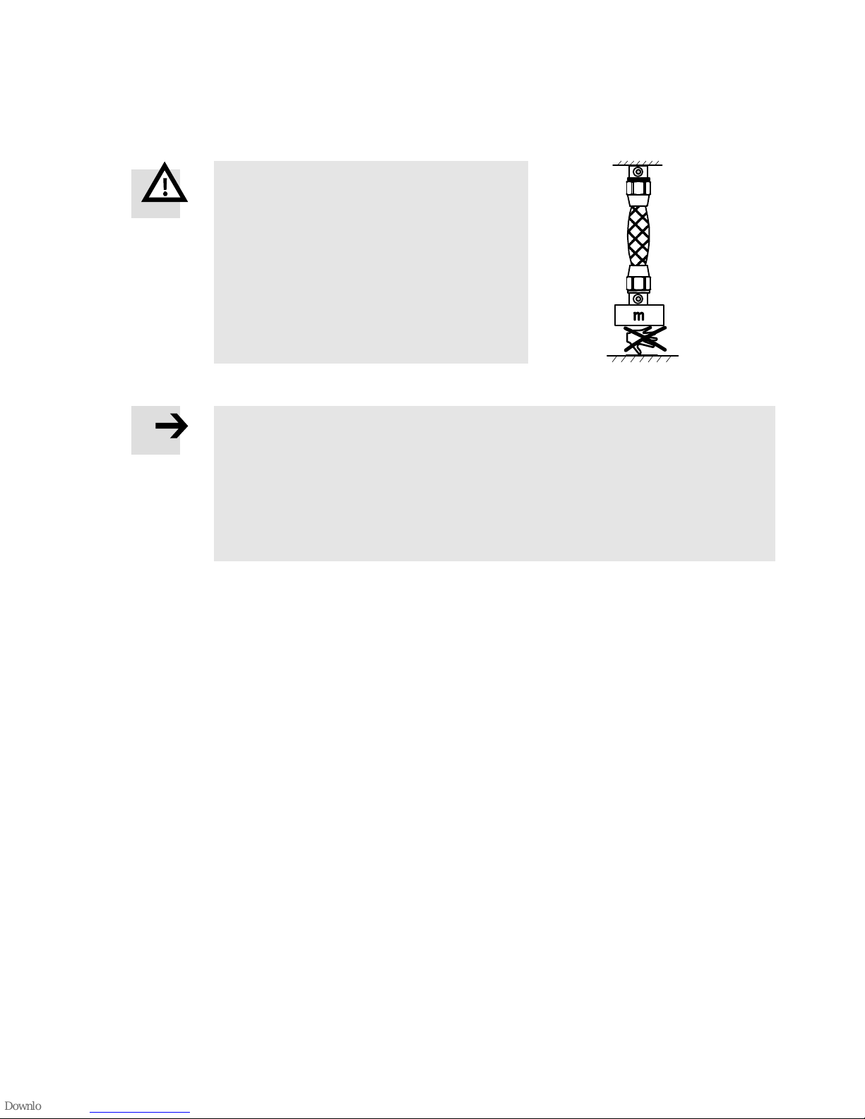
Warning
Unexpected movement of components.
Injury due to impact or pinching.
Protect positioning range from manipulation
(e.g. with protective guards).
Make sure that no foreign objects are
present in the work range.
For MAS-…-K with force limiter:
Note
If the limit of the force limiter is exceeded, the safety function of the MAS-…-K is
triggered.
Make sure that all forces lie within the permissible range (è 13 Technical data).
If the maximum permissible force is exceeded, compressed air escapes at the connect
ing flange of the MAS-…-K. As soon as the maximum permissible force is complied with,
the MAS-…-K is ready for operation again.
6.1 Test run
1. Slowly pressurize DMSP/MAS (e.g. with soft-start valve HEL).
2. Check the following points at the DMSP/MAS:
– The required motion sequence is complied with.
– Contraction takes place within the permissible tolerance (max. 25 % of the nominal length).
– The required force is reached/the load is lifted.
– No leakage occurs.
3. End the test run.
4. Vent the fluidic muscle.
Fig. 7
Page 10
DMSP/MAS
10 Festo – DMSP/MAS – 2018-01f English
7 Operation
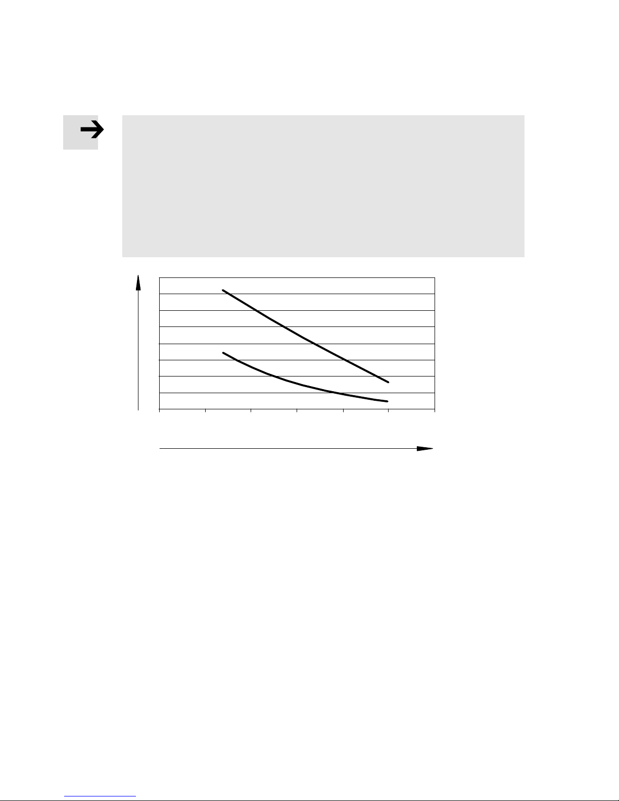
Note
Extreme conditions place stress on the DMSP/MAS.
The following factors lead to a strong reduction in the service life c (è Fig. 8):
– increasing contraction h
– rising applied load m
– rising ambient or operating temperature
Through targeted application of pressure to one side and exhausting on the other side
(“rinsing”), the thermal stressing of the components can be reduced and the service life
of the product increased (not for DMSP-…-CM and MAS-…-MC).
m = 0
m = max
c [n]
h [%]
0 5 10 15 20 25 30
Fig. 8
Protect product during operation from damaging influences. These influences include:
– corrosive coolant or other materials (e.g. ozone)
– oils, greases and grease-solvent vapours
– glowing chips or sparks
Page 11
DMSP/MAS
Festo – DMSP/MAS – 2018-01f English 11
8 Maintenance and care
Inspect DMSP/MAS at the following intervals for signs of aging.
Inspection
interval
1)
Inspection Possible signs of aging Action
Every 500,000
switching cycles
Visual inspection Stress cracks, blisters and other
damage to the surface
Replace DMSP/MAS.
Exposed fibres
Audible check Audible air leakage Inspect pneumatic
connection.
Replace DMSP/MAS.
1) The inspection intervals are reduced by extreme ambient conditions (e.g. strong sunlight, high air humidity, high ozone stress)
Tab. 3
Clean DMSP/MAS as needed with water or soap suds (max. 60 °C).
9 Disassembly and repair
For signs of aging (è 8 Maintenance and care):
Exhaust the complete system and product.
Replace DMSP/MAS completely.
Due to the safety requirements for the connection between the contraction membrane and connecting
flange, a repair is not permissible.
10 Disposal
Dispose of packaging and DMSP/MAS at the end of its useful life through environmentally friendly
recycling in accordance with applicable specifications.
11 Accessories
è www.festo.com/catalogue
Page 12
DMSP/MAS
12 Festo – DMSP/MAS – 2018-01f English
12 Fault clearance
Malfunction Possible cause Remedy
Payload is not raised. Operating pressure is too
low.
Increase operating pressure (observe
maximum permitted value
è 13 Technical data).
The required force is not
reached.
The maximum achievable
force on the DMSP/MAS is
less than the required force.
Select a larger DMSP/MAS.
Clearly audible blowing (only
with MAS-…-K).
Supply pressure is too high. Reduce operating pressure.
Load is too high. Reduce load.
Heavy leakage Diaphragm is worn out. Replace DMSP/MAS.
DMSP/MAS does not reach
the desired speed.
Air volume is lacking. Increase connection cross-section.
Place volume upstream.
Use short tubing lines.
Valve is too small. Use a larger valve.
Tab. 4
Page 13
DMSP/MAS
Festo – DMSP/MAS – 2018-01f English 13
13 Technical data
Size 5 10 20 40
Design Fibre-reinforced contracting diaphragm
Mounting position Any
Medium Compressed air in accordance with ISO 85731:2010 [7:4:4]
Permitted operating
pressure
[bar] 0 … 6 0 … 8 0 … 6
Supply port
DMSP M3 G1/8 G1/4 G3/8
MAS – Dependent on the connecting adapter
Contracting diaphragm
inside diameter
[mm] 5 10 20 40
Maximum permissible offset of connections
Angle tolerance 1°
Parallelism tolerance ± 0.5 %1) (up to 400 mm nominal length)
2 mm (from 400 mm nominal length)
Max. permissible pretensioning
1)
DMSP [%] 1 3 4 5
MAS [%] – 3 4 5
MAS-…-K [%] – 3
Max. permissible
contraction
1)
[%] 20 25
Permissible temperature
range
[°C] –5 … +60
Piston force at permissible operating pressure
DMSP
2)
[N] 140 630 1500 6000
MAS
2)
[N] – 630 1500 6000
MAS-…-K
3)
[N] – 400 1200 4000
Max. permissible payload (freely suspended)
DMSP [kg] 5 30 80 250
MAS [kg] – 30 80 250
MAS-…-K
3)
[kg] – 30 60 120
Normal leakage [l/h] 1
Repetition accuracy
1)
[%] 1 (cyclical)
Materials
Connecting flange Al (anodised); St (galvanized); NBR
Contracting diaphragm Chloroprene, aramide
Adhesive Loctite 243
1) In % of the nominal length (= visible area of the load-free contracting diaphragm)
2) At minimum nominal length, the force is reduced by about 10%.
3) With force compensator
Tab. 5
Page 14
DMSP/MAS
14 Festo – DMSP/MAS – 2018-01f English
14 Characteristic curves
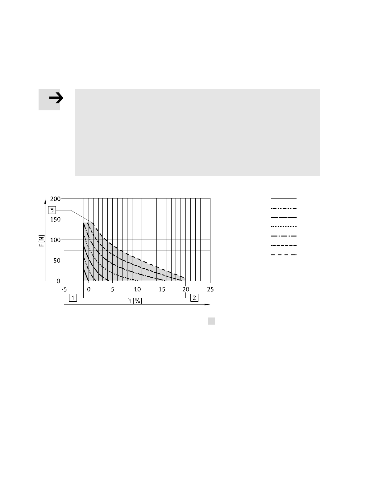
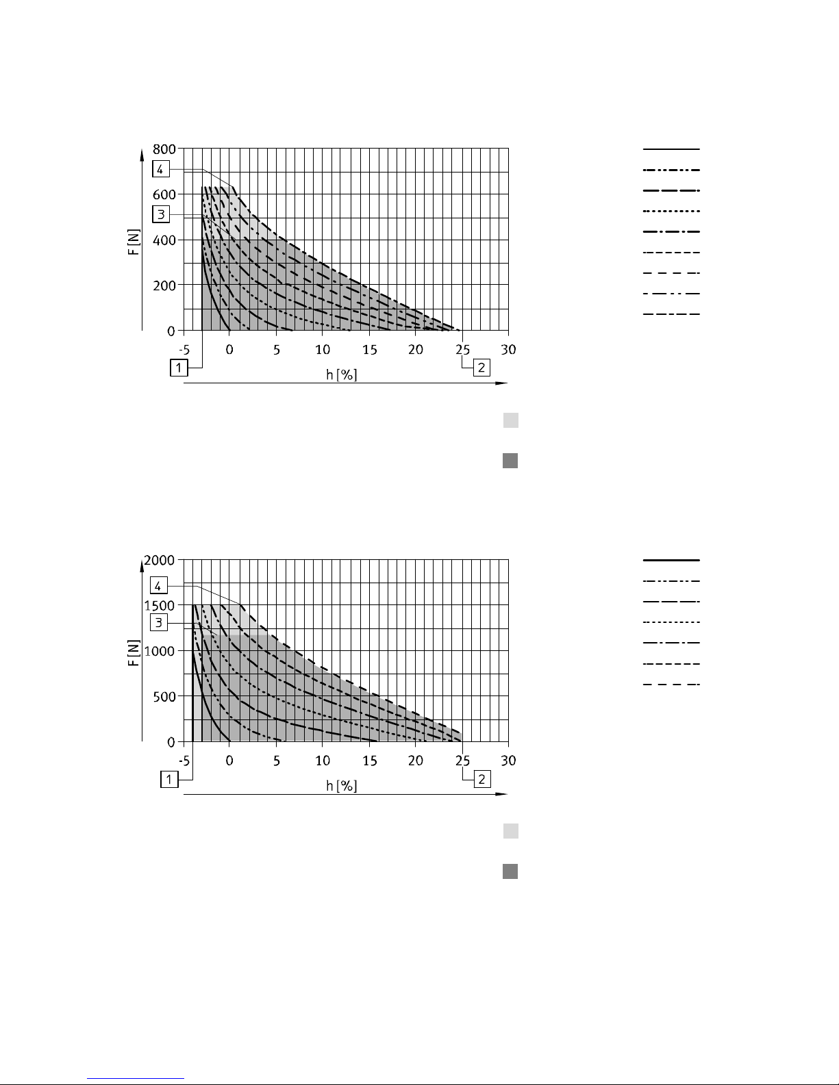
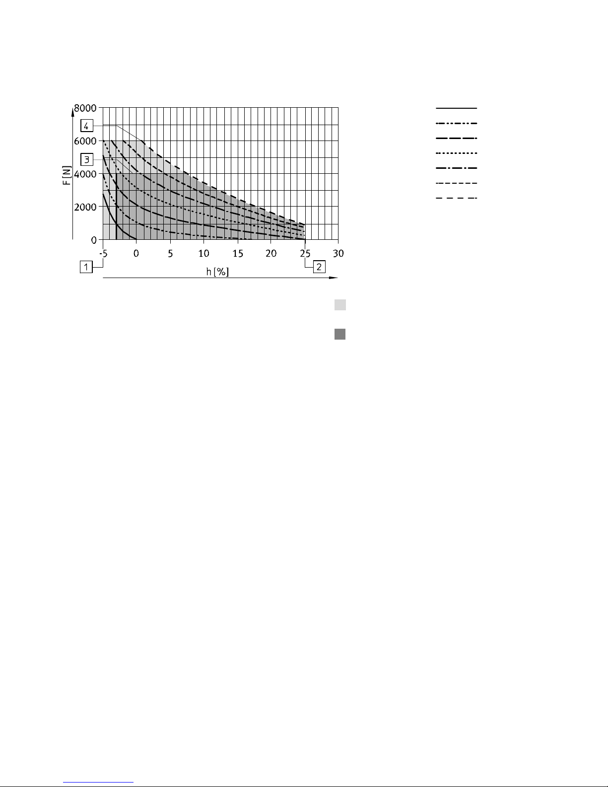
Permissible force F [N] dependent on the contraction h [% of the nominal length]
(nominal length = visible area of the load-free contracting diaphragm)
Note
Deviation of the theoretical force up to 10 %.
The actual force dependent on the contraction can vary according to the following char
acteristics:
– material
– production variation
– nominal length
The deviation can be compensated if the pressure is adapted up to the maximum per
missible operating pressure.
DMSP-5
0 bar
1 bar
2 bar
3 bar
4 bar
5 bar
6 bar
1 Max. pretensioning
2 Max. permissible contraction
3 Theoretical force (140 N) at max. operating pressure
Permissible work space with
DMSP-5
Fig. 9
Page 15
DMSP/MAS
Festo – DMSP/MAS – 2018-01f English 15
DMSP/MAS-10
0 bar
1 bar
2 bar
3 bar
4 bar
5 bar
6 bar
7 bar
8 bar
1 Max. pretensioning
2 Max. permissible contraction
3 With force limiter at 400 N
4 Theoretical force (630 N) at max. operating pressure
Permissible work space with
DMSP/MAS-10
Work space with force limiter for
MAS-10-...-K
Fig. 10
DMSP/MAS-20
0 bar
1 bar
2 bar
3 bar
4 bar
5 bar
6 bar
1 Max. pretensioning
2 Max. permissible contraction
3 With force limiter at 1200 N
4 Theoretical force (1500 N) at max. operating pressure
Permissible work space with
DMSP/MAS-20
Work space with force limiter for
MAS-20-...-K
Fig. 11
Page 16
DMSP/MAS
16 Festo – DMSP/MAS – 2018-01f English
DMSP/MAS-40
0 bar
1 bar
2 bar
3 bar
4 bar
5 bar
6 bar
1 Max. pretensioning
2 Max. permissible contraction
3 With force limiter at 4000 N
4 Theoretical force (6000 N) at max. operating pressure
Permissible work space with
DMSP/MAS-40
Work space with force limiter for
MAS-40-...-K
Fig. 12
Page 17

DMSP/MAS
Festo – DMSP/MAS – 2018-01f 17
Page 18

Reproduction, distribution or sale of this document or communica
tion of its contents to others without express authorization is
prohibited. Offenders will be liable for damages. All rights re
served in the event that a patent, utility model or design patent is
registered.
Copyright:
Festo AG & Co. KG
Ruiter Straße 82
73734 Esslingen
Germany
Phone:
+49 711 347-0
Fax:
+49 711 347-2144
E-mail:
[email protected]
Internet:
www.festo.com
 Loading...