

Page 1
Pneumatischer Linearantrieb
Pneumatic linear drive
DGPI(L)−...−AIF
(de) Bedienungs−
anleitung
(en) Operating
instructions
(es) Instrucciones
de utilización
(fr) Notice
d’utilisation
(it) Istruzioni
per l’uso
(sv) Bruksanvisning
683 281
0409a
Page 2

DGPI(L)−...−AI F
Esbedeuten/Symbols/Símbolos/
Symboles/Simboli/Teckenförklaring:
Warnung
Warning, Caution
Atención
Avertissement
Avvertenza
Varning
Hinweis
Please note
Por favor, observar
Note
Nota
Notera
Umwelt
Antipollution
Reciclaje
Recyclage
Riciclaggio
Återvinning
Zubehör
Accessories
Accesorios
Accessoires
Accessori
Tillbehör
Einbau und Inbetriebnahme nur von qualifi
ziertem Fachpersonal, gemäß Bedienungs
anleitung.
Fitting and commissioning to be carried out
by qualified personnel only in accordance
with the operating instructions.
El montaje y la puesta en funcionamiento,
debe ser realizado exclusivamente por
personal cualificado y siguiendo las
instrucciones de utilización.
Montage et mise en service uniquement par
du personnel agréé, conformément aux
instructions d’utilisation.
Montaggio e messa in funzione
devono
essere effettuati da personale specializzato
ed autorizzato in confomità alle istruzioni per
l’uso.
Montering och idrifttagning får endast utföras
av auktoriserad fackkunnig personal i
enlighet med denna bruksanvisning.
Siehe weiteres Dokument
See further document
Deutsch 3. . . . . . . . . . . . . . . . . . .
. . . . . . . . . . . . . . . . . . . . . . . . . . . . . . . . . . . . . . . . . . . . . . . . . . .
English 21. . . . . . . . . . . . . . . . . . . . . . . . . . . . . . . . . . . . . . . . . . . . . . . . .
Español 39. . . . . . . . . . . . . . . . . . . . . . . . . . . .
Français 57. . . . . . . . .
. . . . . . . . . . . . . . . . . . . . . . . . . . . . . . . . . . . . . . . . . . . . . . . . . . . . . . . . . . . .
Italiano 75. . . . . . . . . . . . . . . . . . . . . . . . . . . . . . . . . . . . . . . .
Svenska 93. . . . . . . . . . . . . . . . . . .
2
. . . . . . . . . . . . . . . . . . . . . . . . . . . . . . . . . . . . . . . . . . . . . . . . . .
. . . . . . . . . . . . . . . . . . . . . . . . . . . . . . . . . . . . . . . . .
. . . . . . . . . . . . . . . . . . . . . . . . . . . . . .
. . . . . . . . . . . . . . . . . . . . .
Festo DGPI(L)−...−AIF 0409a de
Page 3

DGPI(L)−...−AI F
Pneumatischer Linearantrieb DGPI(L)−Ū−AIFDeutsch
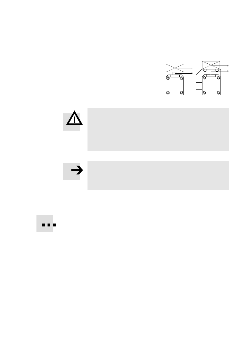
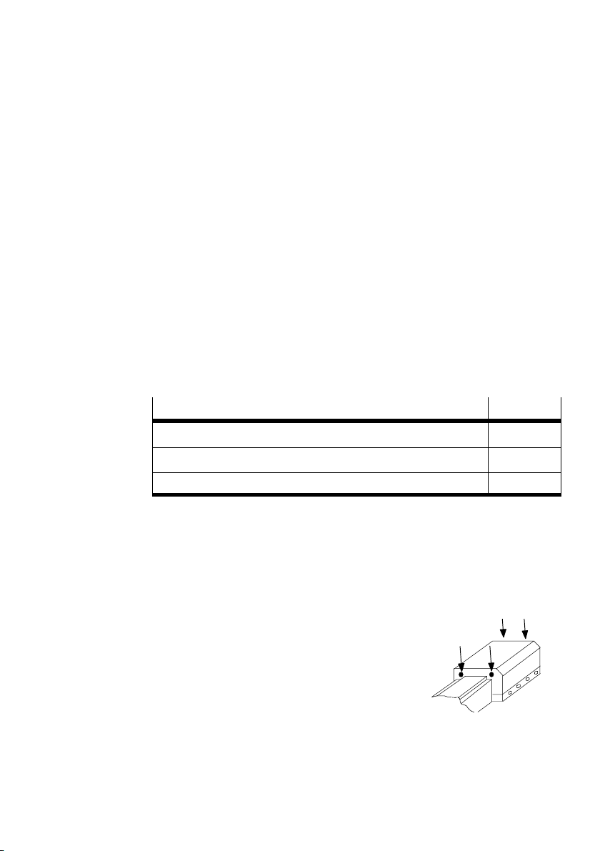
1 Bedienteile und Anschlüsse
aB
aC
aA
1
Druckluftanschluss indirekt
2 Druckluftanschluss direkt
3 Schmiernippel für Wälzlager
123
8 Mitnehmer
9 Bohrung für Erdungsanschluss
aJ Messsystem−Anschluss
4 5
9
6
7
8aJ
4 Nut zur Befestigung der Nutzlast
5 Läufer
6 Bohrung zur Befestigung der Nutzlast
7 Gewinde zur Befestigung der Nutzlast
Bild1
Festo DGPI(L)−...−AIF 0409a Deutsch
aA Gewinde zur Befestigung des Antriebs
aB Stellschraube für Endlagendämpfung PPV
aC Druckluftanschluss bei Variante ...−D2
3
Page 4
DGPI(L)−...−AI F
2Funktion
Durch wechselweise Belüftung der Druckluftanschlüsse bewegt sich der Innenläu
fer im Rohr hin und her. Durch eine starre Verbindung bewegt sich der Außenläufer
mit. Den dazu notwendigen Schlitz im Zylinderrohr überspannt ein Bandsystem.
Das integrierte Wegmess−System erlaubt es, die Position des Läufers zu jeder Zeit
eindeutig zu bestimmen.
3 Anwendung
Bestimmungsgemäß dient das Produkt zum pneumatischen Positionieren von
Massen.
Das integrierte Wegmess−System mit CAN−Achsinterface passt zum:
Endlagenregler SPC11−MTS−AIF (Soft Stop) oder zum
Achsinterface SPC−AIF−MTS mit Achscontroller SPC200.
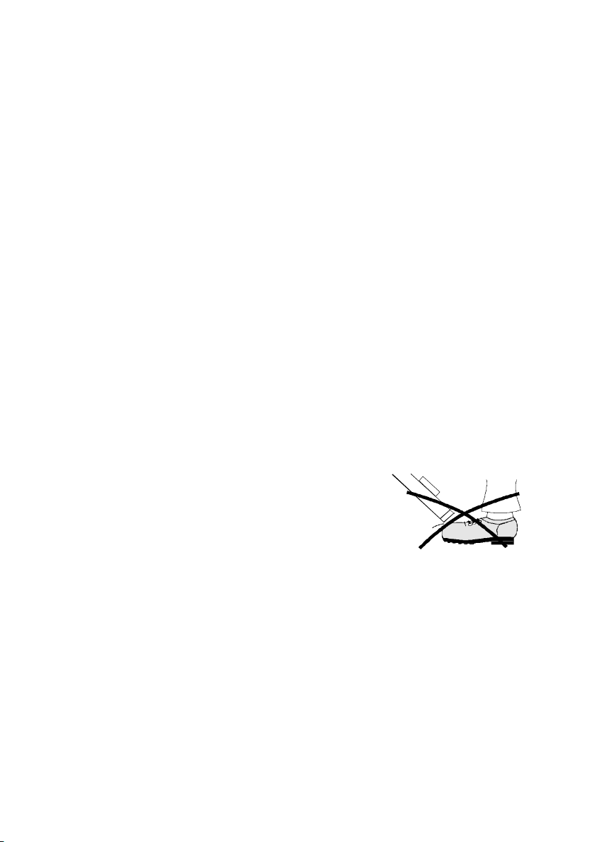
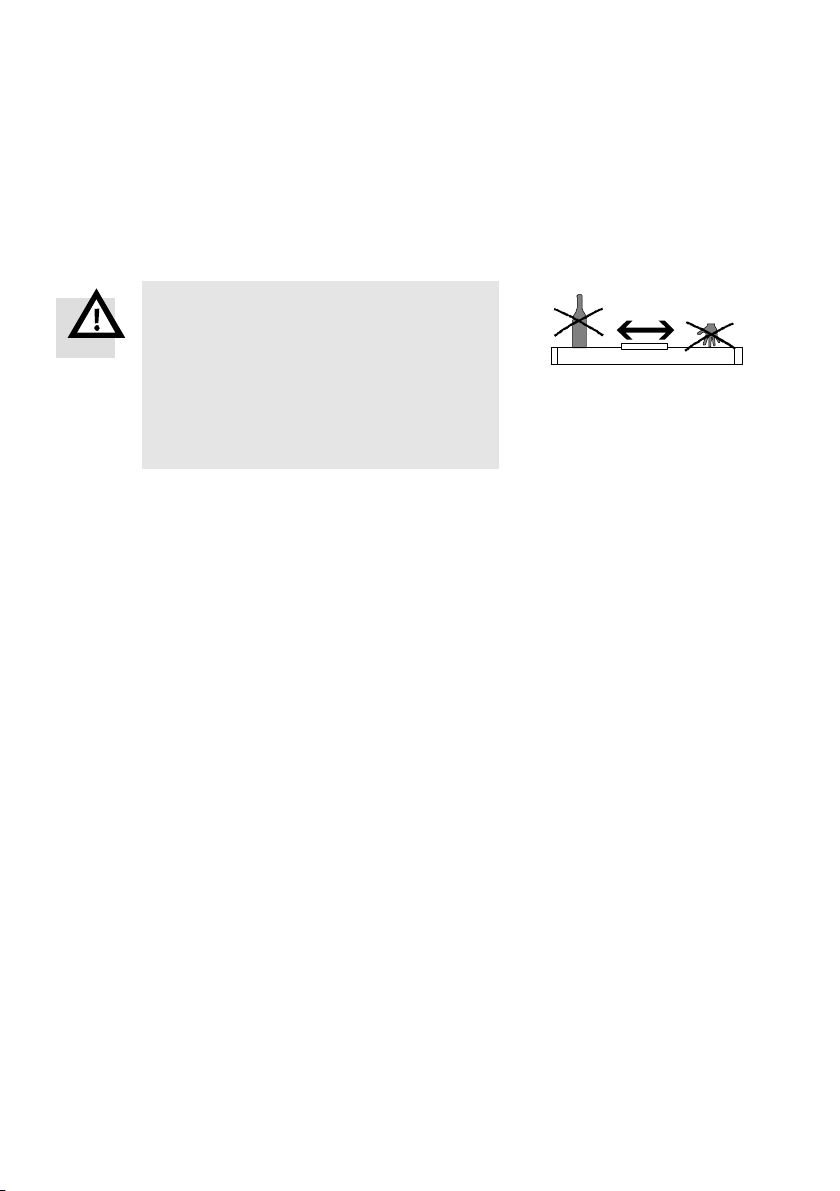
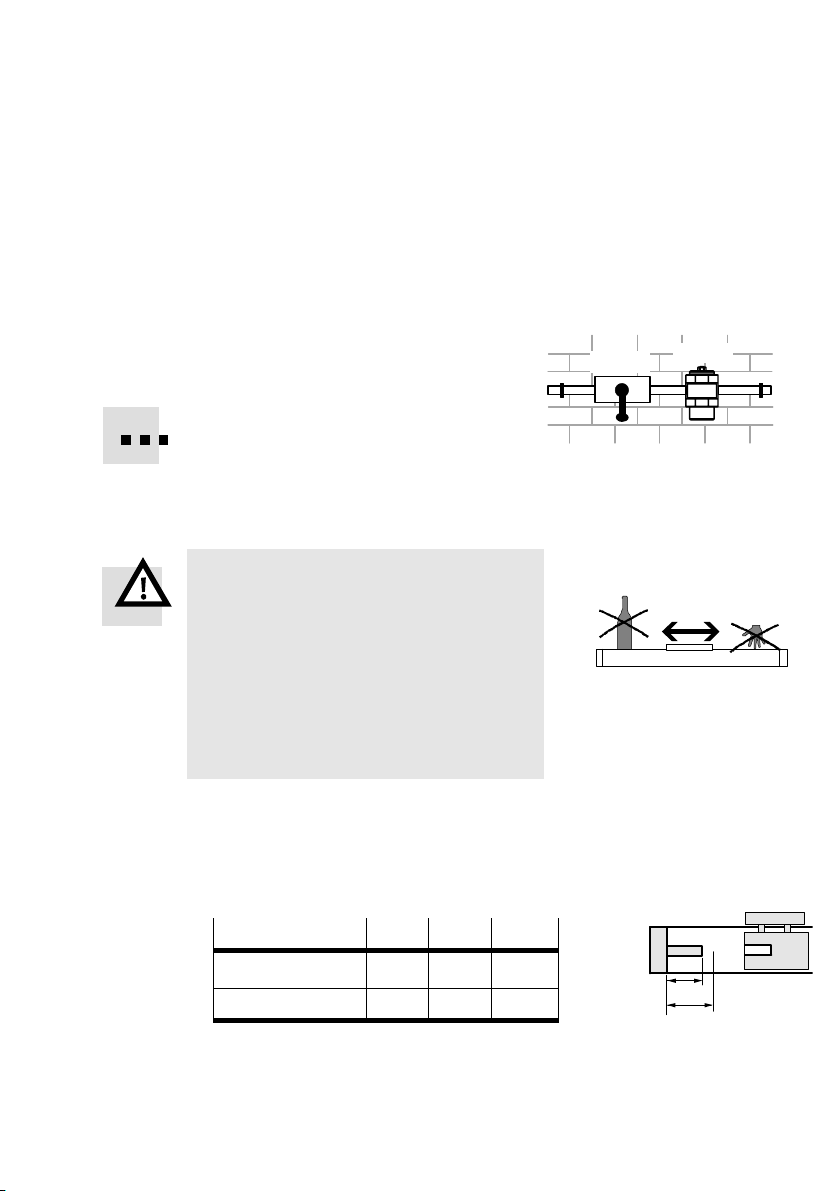
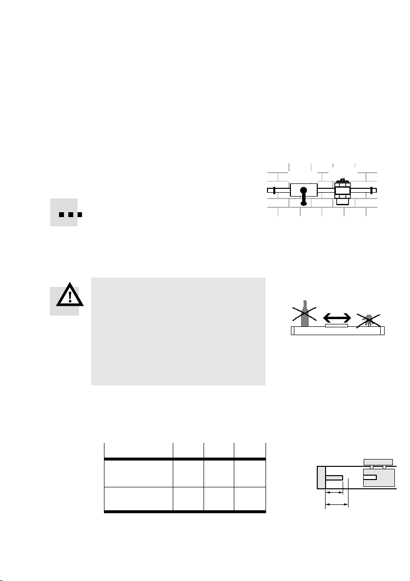
4Transport und Lagerung
Berücksichtigen Sie das Gewicht des
DGPI(L)−....
Je nach Ausführung wiegt der DGPI(L)−...
über80kg.
4
Bild2
Festo DGPI(L)−...−AIF 0409a Deutsch
Page 5
DGPI(L)−...−AI F
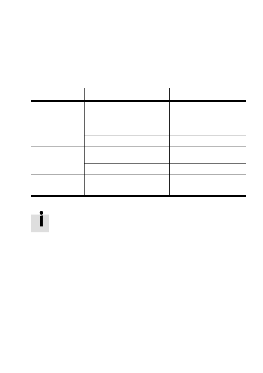
5Voraussetzungen für den Produkteinsatz
Hinweis
Durch unsachgemäßen Gebrauch entstehen Fehlfunktionen.
S Stellen Sie sicher, dass die Vorgaben dieses Kapitels stets eingehalten
werden.
S Berücksichtigen Sie die Warnungen und Hinweise am Produkt und in den
zugehörigen Bedienungsanleitungen.
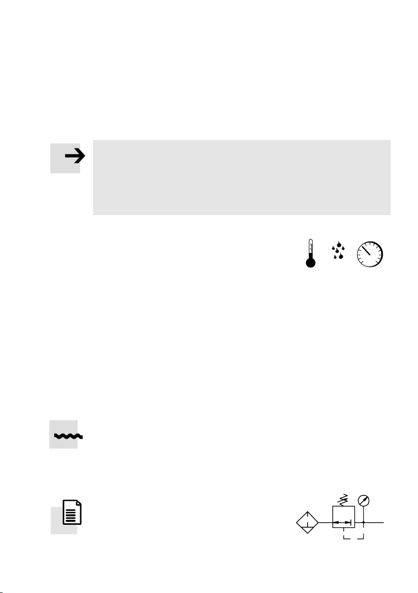
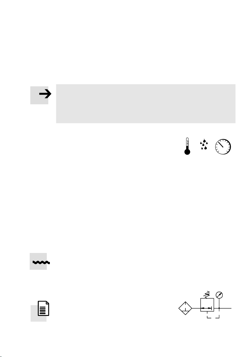
S Vergleichen Sie die Grenzwerte in dieser
[%] [mbar][°C]
Bedienungsanleitung mit denen Ihres
Einsatzfalls (z.B. Kräfte, Momente,
Temperaturen, Massen).
Nur die Einhaltung der Belastungsgrenzen
ermöglicht ein Betreiben
des Produkts
Bild3
gemäß der einschlägigen Sicherheitsrichtlinien.
S Berücksichtigen Sie die Umgebungsbedingungen am Einsatzort.
Korrosive Umgebungen verkürzen die Lebensdauer des Produkts (z.B. Ozon).
S Berücksichtigen Sie die Vorschriften der Berufsgenossenschaft, des Techni
schen Überwachungsvereins, des VDE oder entsprechende nationale Bestim
mungen.
S Verwenden Sie das Produkt im Originalzustand ohne jegliche eigenmächtige
Veränderung.
S Entfernen Sie die Verpackungen wie
Folien, Kappen, Kartonagen.
Ausnahme: Haftetiketten an Druckluftanschlüssen (Verschmutzungsgefahr)
Die Verpackungen sind vorgesehen für eine Verwertung auf stofflicher Basis
(Ausnahme: Ölpapier = Restmüll).
S Lassen Sie die Abdeckkappen aus blauem Kunststoff an den Abschlussdeckeln
aufgesteckt. Diese schützen die Spannvorrichtung des Bandsystems gegen
äußere Einflüsse.
S Sorgen Sie für Druckluft mit ordnungs
LF−... LR−...
gemäßer Aufbereitung (s. Techn. Daten).
S Lesen
Sie auch die Dokumentation zu
Ihrem Steuerungssystem (z.B. SPC200,
SPC11).
Bild4
Festo DGPI(L)−...−AIF 0409a Deutsch
5
Page 6
DGPI(L)−...−AI F
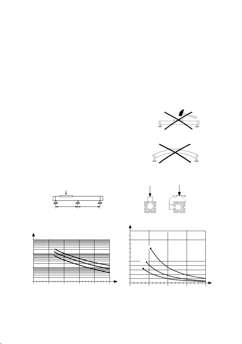
6 Einbau
Einbau mechanisch
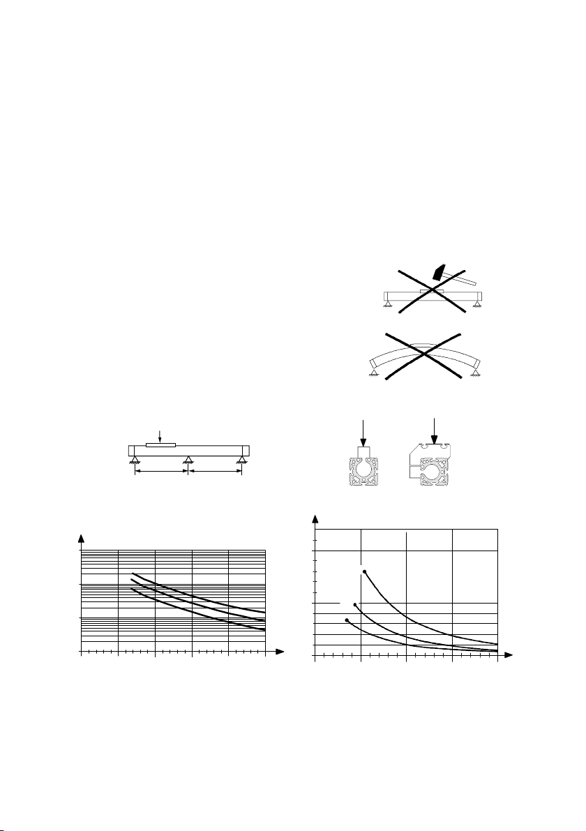
S Vermeiden Sie, dass das Bandsystem
beschädigt wird.
Beschädigungen am Bandsystem führen
zu Leckage und mindern die Leistungs
fähigkeit des DGPI(L)−....
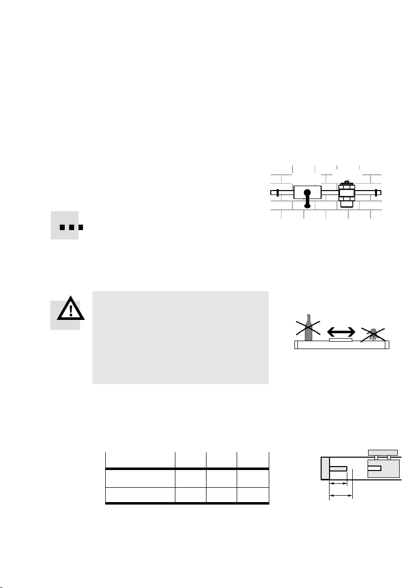
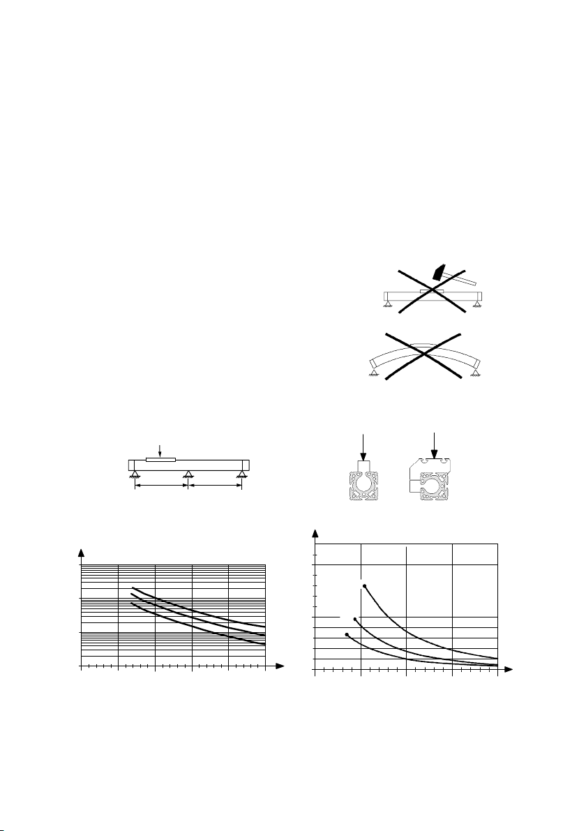
S Achten Sie auf einen Einbau ohne
Verspannungen und Biegungen.
Bei Bedarf verwenden Sie hierzu die
Profilbefestigung (Mittenstütze)
TypMUP−....
Bild5
Bild6
F
l l
F[N]
100000
10000
1000
100
500 1000 1500 2000 2500 3000
Bild7: Notwendige Stützabstände
6
l[mm]
ø80
ø63
ø50
F [N]
1000
500
0
1000
DGPI(L) −
32
25
F
40
1500
2000 2500
Festo DGPI(L)−...−AIF 0409a Deutsch
F
3000
l [mm]
Page 7

DGPI(L)−...−AI F
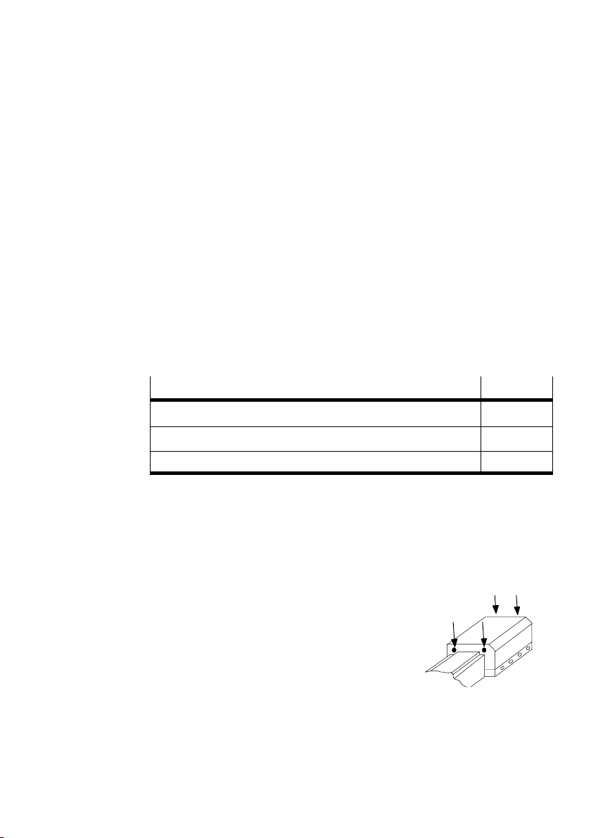
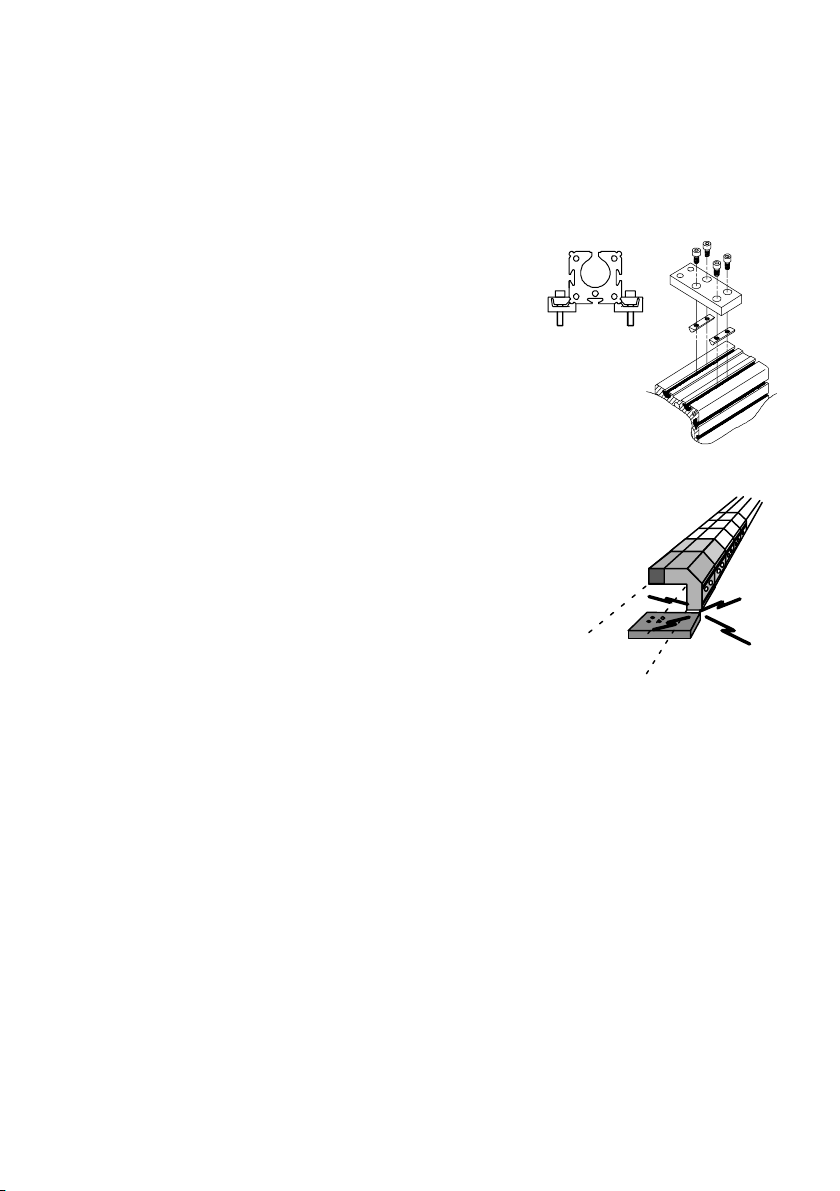
Zum Anbau von Profilbefestigungen MUP−...:
1. Platzieren Sie die Profilbefestigungen am
2. Drehen Sie die Befestigungsschrauben
3. Stellen Sie sicher, dass sich die Profilbe
DGPI(L)−... gemäß Bild8.
Durch Verkippen gleiten die Nutensteine
bei den Baugrößen 32...63 an jeder Stelle
des Profils in die Nut.
gleichmäßig fest.
festigungen außerhalb des Verfahrbereichs
des Läufers befinden.
Verschieben Sie den Läufer hierfür einmal
den gesamten Hub.
über
Ø 25
Ø 32 ...63
Bild8
Festo DGPI(L)−...−AIF 0409a Deutsch
Bild9
7
Page 8
DGPI(L)−...−AI F
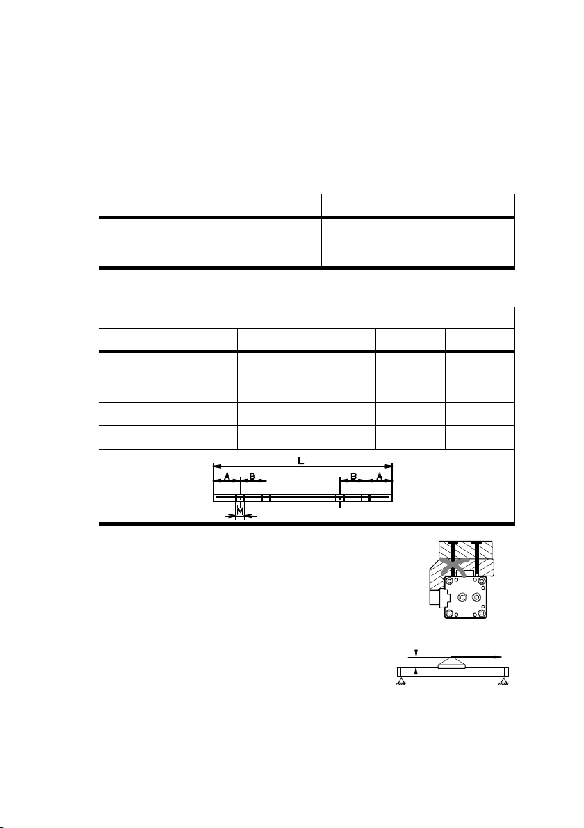
Zur Befestigung der Nutzlast:
1. Wählen Sie eine Befestigungsmöglichkeit:
DGPIL−...
1. Nutensteine NSTL−... am Läufer 4
2. Gewindebohrungen und Zentrierelemente
(siehe Zubehör) am Läufer
Bild10: Befestigungsmöglichkeiten der Nutzlast (siehe Bild 1)
DGPI−...
3. Bohrungen 6 und Gewinde 7 im
Mitnehmer 8
Maße der Nutensteine NSTL−... [mm]
j 25 32 40 50 63
L 100 128 166 199 229
A 13 14 25 24 30
B 15 15 20 20 35
M M5 M5 M5 M8 M8
Bild11
Im Falle von Befestigungsmöglichkeit 2
müssen die Schrauben kürzer als die
Gewindebohrung sein.
Bild12
2. Platzieren Sie die Nutzlast so, dass das
Kippmoment aus der Kraft F parallel zur
Bewegungsachse und dem Hebelarm a
klein bleibt.
a
Bild13
F
Bei Nutzlasten mit eigener Führung:
S Justieren Sie die Führungen von Nutzlast und DGPI(L) exakt parallel.
8
Festo DGPI(L)−...−AIF 0409a Deutsch
Page 9

DGPI(L)−...−AI F
B
Einbau, pneumatisch
Bei Einbau in senkrechter oder schräger Lage:
Warnung
Im Falle eines Druckabfalls fällt die bewegliche Masse nach unten. Unkontrol
liert bewegte Massen schädigen Personen oder Gegenstände (Quetschungen)
(bewegliche Masse = Läufermasse + Masse der Nutzlast).
S Lesen Sie die Dokumentation zu Ihrem Steuerungssystem (z.B. SPC11/200).
Dort finden Sie pneumatische Schaltungen, mit denen das Herabfallen
verzögert werden kann.
S Wählen Sie
Zu den ab Werk vorgesehenen Anschlüssen
die Druckluftanschlüsse.
A
(A) existieren Alternativanschlüsse (B,C).
In diesen sitzen Verschlussschrauben.
Bild14
C
Bei Variante ...−D2 (mit beidseitigem Luftanschluss):
Hier kann der Luftanschluss nicht einseitig vorgenommen werden.
Bei Hublängen > 500 mm:
Bei Ansteuerung des DGPI(L)−... mit Hilfe von SPC11 oder SPC200 muss die
Drucklufteinspeisung beidseitig erfolgen (Variante D2).
beidseitige Einspeisung garantiert optimale Dynamik.
Nur die
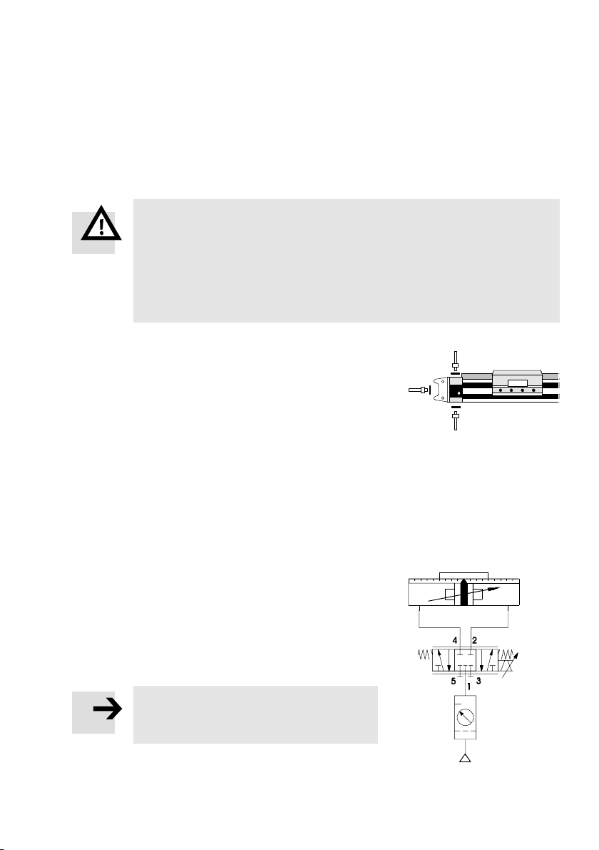
Zur Ansteuerung des DGPI(L)−...:
S Verwenden Sie das Proportional−Wege
ventil MPYE−... für die Geschwindigkeits
steuerung und das Positionieren.
Bild15 zeigt eine Beispielschaltung.
Hinweis
Diese Schaltung eignet sich nicht, um den
Läufer im Falle eines Druckausfalls anzu
halten.
Bild15
5 ìm
Festo DGPI(L)−...−AIF 0409a Deutsch
9
Page 10
DGPI(L)−...−AI F
4
5
3
6
Einbau, elektrisch
S Verkabeln Sie den Erdungsanschluss mit Erdpotenzial.
2
Kabelquerschnitt min. 1,5mm
.
Kabellänge max. 10 m.
S Drehen Sie hierfür die Schraube mit Schneidgewinde (im Lieferumfang
enthalten) in die Bohrung für den Erdungsanschluss 9 ein (siehe Bild 1).
Dies gewährleistet den Kontakt trotz Eloxalschicht.
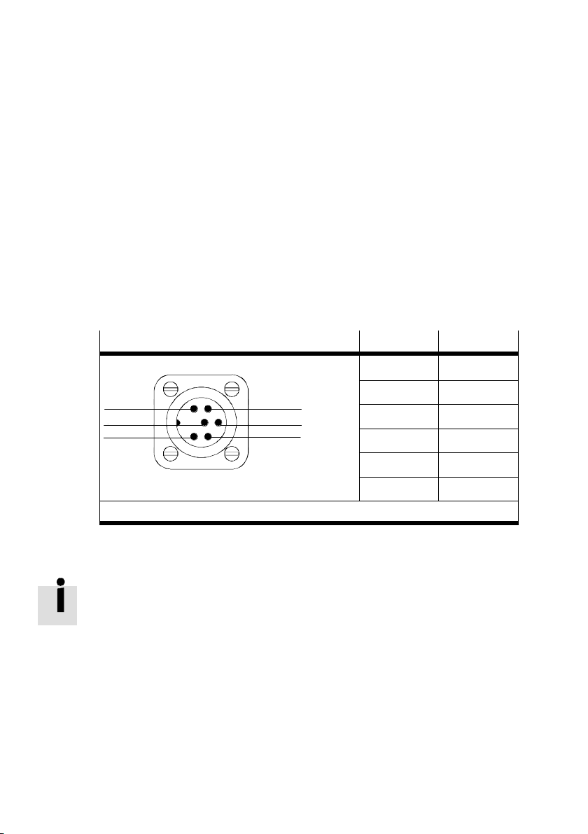
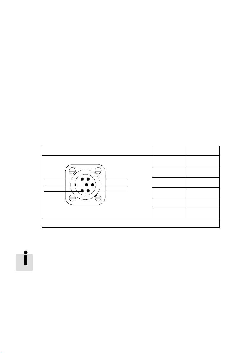
S Verkabeln Sie den Messsystem−Anschluss mit dem Steuerungssystem.
Hierzu darf nur das Originalkabel verwendet werden (PIN−Belegung siehe
Bild16).
Messsystem−An
6
1
n.c. = nicht belegt (not connected)
Bild16
schluss PIN Belegung
1 CAN−Low
2 CAN−High
3
2
3 n.c.
4 n.c.
5 DC +24 V
6 0 V
Beachten Sie, dass sich der Permanentmagnet, der im Kolben eingebaut ist, nur
zum Betrieb des integrierten Messsystems eignet.
Nicht unterstützt werden Näherungsschalter mit magnetischer Betätigung.
10
Festo DGPI(L)−...−AIF 0409a Deutsch
Page 11
DGPI(L)−...−AI F
7 Inbetriebnahme
Inbetriebnahme Gesamtanlage
S Belüften Sie die Anlage insgesamt lang
sam.
Dadurch vermeiden Sie Bewegungen
unkontrollierter Art.
Zur langsamen Einschaltbelüftung dient
das Druckaufbau−Ventil Typ HEL−... /
HEM−....
Inbetriebnahme DGPI(L)−...
Warnung
S Stellen Sie sicher, dass im Verfahrbereich
niemand in die Laufrichtung der bewegten
Bauteile greift (z.B. durch Schutzgitter).
sich keine Fremdgegenstände befinden.
Nur bei völligem Stillstand der Masse darf
ein Greifen an den DGPI(L)−... möglich sein.
Bild17
QH−...
Bild18
HEL−...
Bei Ansteuerung mit SPC11/200:
1. Beachten Sie die Hubreduzierung pro Endlage.
Innerhalb der Hubreduzierung steht nur ein
zur Verfügung.
DGPI(L)−... 25 32 40...80
Dämpfungslänge d 18 mm 20 mm 30 mm
Hubreduzierung r 25 mm 25 mm 35 mm
Es ist werksseitig vorgesehen, dass die pneumatische Endlagendämpfung PPV
bei Ansteuerung mit SPC11/200 beidseitig ganz geöffnet ist.
Festo DGPI(L)−...−AIF 0409a Deutsch
eingeschränktes Positionierverhalten
d
Bild19
r
11
Page 12
DGPI(L)−...−AI F
Bei hohen Anforderungen an das Positionierverhalten:
2. Vergrößern Sie die Hubreduzierung.
Durch eine Hubreduzierung von 10 % pro
Endlage erreichen Sie das bestmögliche
Positionierverhalten.
Bild20
80%
100%
Zum Schutz der Endlagen bei Bedien− oder Systemfehlern:
3. Drehen Sie die Stellschrauben der Endlagendämpfung PPV ganz zu, falls Sie
diese als Luftpolster verwenden wollen.
Warnung
Bei Nutzlasten mit Überstand in
Schlittenlängsrichtung:
S Beachten Sie, dass die Stell
schrauben nur bei Stillstand des
DGPI(L)−... verdreht werden
dürfen.
Bild21
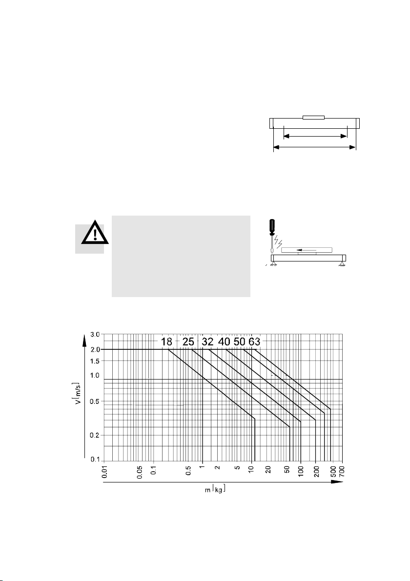
Das folgende Bild zeigt das maximale Dämpfungsvermögen der PPV in
Abhängigkeit von Läufer−Geschwindigkeit und Nutzlast:
Bild22
12
Festo DGPI(L)−...−AIF 0409a Deutsch
Page 13
DGPI(L)−...−AI F
Die Kennlinien in Bild22 gelten für:
Schwerpunktabstand r = 50 mm
m
r
m
Druck: 6 bar
Temperatur: 20 °C
Einbaulage: horizontal
Bild23
Warnung
Ohne externe Abfangvorrichtungen kann ein Überschreiten der
in Bild22 angegebenen Massen und Geschwindigkeiten zur
Zerstörung des DGPI(L)−... führen.
Auch bei Störungen dürfen die zulässigen Kräfte und Momente
nicht überschritten werden.
Hinweis
Bei geschlossener Endlagendämpfung PPV kann sich die
Dynamik des Positioniervorgangs in der Nähe der Endlagen
verringern.
4. Verwenden Sie Stoßdämpfer, falls Sie auch in der Nähe der Endlagen mit hoher
Dynamik positionieren wollen.
Tipp:
Verwenden Sie Stoßdämpferhalter, die über den gesamten Hub verschiebbar
sind (Typ KYP−...).
r
Festo DGPI(L)−...−AIF 0409a Deutsch
13
Page 14
DGPI(L)−...−AI F
8 Bedienung und Betrieb
Warnung
S Stellen Sie sicher, dass im Verfahrbereich
niemand in die Laufrichtung der bewegten
Bauteile greift (z.B. durch Schutzgitter).
sich keine Fremdgegenstände befinden.
Nur bei völligem Stillstand der Masse darf
ein Greifen an den DGPI(L)−... möglich sein.
Bei Änderungen der Nutzlastmasse oder des Schwerpunktabstandes:
S Prüfen Sie, ob die Belastungen des DGPI(L)−... weiterhin
liegen: siehe Kapitel Inbetriebnahme, Bild22.
Bei Änderungen des Nutzhubs:
S Prüfen Sie, ob der Nutzhub innerhalb der zulässigen Grenzen bleibt: siehe
Kapitel Inbetriebnahme unter Hubreduzierung".
Bild24
im zulässigen Bereich
14
Festo DGPI(L)−...−AIF 0409a Deutsch
Page 15
DGPI(L)−...−AI F
9Wartung und Pflege
Zur Pflege des Bandsystems:
S Reinigen Sie das Bandsystem bei Bedarf mit einem weichen Lappen.
Als Reinigungsmedien sind zulässig: alle Werkstoff schonenden Medien.
S Fetten Sie das Bandsystem oberflächlich, falls es keine Fettschicht mehr
aufweist. Fettsorte: LUB−KC1 (silikonfrei) von Festo.
Zur Schmierung der Wälzlager der Typen DGPIL−...:
1. Stellen Sie sicher, dass die Schmierintervalle gemäß Bild25
den. Bei geringerer Laufleistung ist nach spätestens 3 Jahren zu schmieren.
Schmierintervalle und Fettsorten
Erstintervall 5000 km
Folgeintervall mit LUB−KC1 400 km
eingehalten wer
Oder: Folgeintervall mit LUB−RN2 5000 km
Bild25
S Beachten Sie, dass die Schmierinter valle verkürzt werden müssen bei:
staubiger und schmutziger Umgebung
Arbeitshüben < 50 mm
Geschwindigkeiten > 2 m/s
2. Entlüften Sie den DGPIL−....
3. Fetten Sie die Wälzlager an allen vier
Schmiernippeln.
Dazu dient eine Fettpresse mit Nadel−
Spitzmundstück (siehe Zubehör).
S Schieben Sie den Läufer während des
Fettens hin und her. Sonst füllen sich
die Fetträume nicht gleichmäßig.
4. Fetten Sie die Führungsschiene oberflächlich, falls sie keine Fettschicht mehr
aufweist (Fettsorte: siehe Bild25).
Festo DGPI(L)−...−AIF 0409a Deutsch
Bild26
15
Page 16

DGPI(L)−...−AI F
10 Reparatur
S Sorgen Sie dafür, dass eine Überholung des DGPI(L)−... nur durch unseren
Reparaturservice vorgenommen wird.
Die Reparaturvorgänge erfordern Einstellarbeiten mit sehr feinen Abstim
mungen.
11 Zubehör
Bezeichnung Typ
Für die Befestigung des DGPI(L)−...:
Fußbefestigung
Profilbefestigung (Mittenstütze)
Für die Befestigung der Nutzlast am Läufer:
Zentrierstifte / Zentrierhülsen
Zentralbefestigung
Nutensteine (L für Läufer)
HP−...
MUP−...
ZBS−... / ZBH−...
SLZZ−...
NST(L)−...
Nutenabdeckschiene ABP−..
Stoßdämpfer
Stoßdämpferhalter, beliebige Position
Verbindungsbausatz Schwalbenschwanz auf Läufer quer
Verbindungsbausatz Schwalbenschwanz auf Läufer längs /
auf Deckel
Kreuzverbindungsbausatz Läufer HMVK−...
Verbindungswinkel zu Profilsystem HMBV
Kraftbrücke AK−...
Fettpresse mit Nadel−Spitzmundstück
Fette: siehe Kapitel Wartung
16
YSR−...−C / YSRW−...
KYP−...
HMAV (für HMP)
HMSV (für SLT)
HAPB / HMVA
647 958
Festo DGPI(L)−...−AIF 0409a Deutsch
Page 17
DGPI(L)−...−AI F
12 Störungsbeseitigung
Störung Mögliche Ursache Abhilfe
Läufer kommt nicht in
die Hubendlage
Starke Leckage Zylinder verspannt eingebaut Zylinder auf ebenem Untergrund
Zylinder erreicht nicht
die gewünschte
Geschwindigkeit
Störungen bei der
Positionsabfrage
Stellschraube der Endlagendämpfung
vollständig geschlossen
Dichtung verschlissen Zur Reparatur an Festo schicken.
Fehlendes Luftvolumen Anschlussquerschnitte
Hohe Reibung oder Gegenkraft Größeren Antrieb wählen
Starke externe Magnetfelder,
Umwelteinflüsse außerhalb der
Spezifikation
Stellschraube öffnen
befestigen.
vergrößern; Volumen vorschalten
Externe Magnetfelder beseitigen,
Spezifikation beachten
Weitere Hinweise zur Störungsbeseitigung siehe Dokumentation zum Steuerungs
system (z.B. SPC11/200).
Festo DGPI(L)−...−AIF 0409a Deutsch
17
Page 18

DGPI(L)−...−AI F
13 Technische Daten
Pneumatisch, mechanisch
Baugröße
Medium Druckluft, getrocknet, gefiltert (5 ìm), ungeölt
Bauart Doppeltwirkender Pneumatik−Zylinder ohne Kolbenstange mit starrer
Betriebsdruck
(min. ... max.)
Temperatur min. −10 ... max. +60 °C
Einbaulage Beliebig
Endlagendämpfung (PPV) Pneumatisch, einstellbar
Dämpfungslänge 18 mm 20 mm 30 mm
Hubreduzierung je
Endlage
Hubkraft
(theor., bei 6 bar)
Luftverbrauch
(theor., pro 10 mm Hub)
Leckage im Neuzustand max. 10 l/h (bei 6 bar) max. 20 l/h (bei 6 bar)
Zul. Nutzlastkomponente
senkrecht zur Zylinder
achse und zul. statische
Läuferkippmomente
25 32 40 50 63
Kolben−Läufer−Verbindung und integriertem Messsystem
2 ... 8 bar 1,5 ... 8 bar
25 mm 35 mm
295 N 483 N 754 N 1178 N 1870 N
0,034 Nl 0,056 Nl 0,088 Nl 0,137 Nl 0,218 Nl
Abhängig von Typ, Geschwindigkeit und Belastungsfall;
rechnerisch zu ermitteln über Katalogangaben
Werkstoffe Zylinderprofil, Mitnehmer, Abschlussdeckel: Al eloxiert/lackiert
18
Dichtungen, Dichtband: NBR/PU
Führungsband, Umlenkung, Schmutzabstreifer: POM
Führungsschiene: St (Wälzführung)
Festo DGPI(L)−...−AIF 0409a Deutsch
Page 19

DGPI(L)−...−AI F
Elektrisch
Wegmesssystem Magnetostriktiv, berührungslos, absolut messend
Schutzart (Messystem inkl. Gehäuse und
Anschlusstechnik)
IP65 (bei ordnungsgemäß montierter Anschlussdose
mit Kabel)
Elektrischer Anschluss 6−poliger Rundstecker nach DIN 45322
Schnittstelle CAN nach ISO/DIS 11898
Datenprotokoll / Übertragungsrate SPC−AIF / 1 Mbit/s
Linearität < ± 0,02 % F.S. (min. ± 50 ìm)
Auflösung Ţ 0,01 mm
Versorgungsspannung 24 V DC (+20 % / −15 %)
Stromaufnahme (Start/Stop) 90 mA typ.
Temperaturkoeffizient < 15 ppm / °C
EMV−Festigkeit (bei geerdetem Zylinder) DIN EN 61000−6−2 / DIN EN 61000−6−3
Festo DGPI(L)−...−AIF 0409a Deutsch
19
Page 20

DGPI(L)−...−AI F
20
Festo DGPI(L)−...−AIF 0409a Deutsch
Page 21

DGPI(L)−...−AI F
Pneumatic linear drive DGPI(L)−Ū−AIFEnglish
1 Operating parts and connections
aB
123
aC
aA
1
Compressed air port indirect
2 Compressed air port direct
3 Lubricating nipple for roller bearing
4 5
9
8aJ
8 Driver
9 Hole for earth connection
aJ Measuring system connection
6
7
4 Groove for fastening the work load
5 Slide
6 Hole for fastening the work load
7 Thread for fastening the work load
Fig.1
Festo DGPI(L)−...−AIF 0409a English
aA Thread for fastening the drive
aB Adjusting screw for end position cushioning
aC Compressed air port on variant ...−D2
21
Page 22

DGPI(L)−...−AI F
2Function
When the compressed air ports are pressurized alternately, the piston moves
backwards and forwards in the tubing. By means of a rigid connection, the outer
slide also moves. The slot in the cylinder barrel required for this is covered by a
band system.
The integrated measuring system enables the position of the slide
tained clearly at any time.
3 Application
This product has been designed for the pneumatic positioning of masses.
The integrated measuring system with CAN axis interface can be used with:
the end position controller SPC11−MTS−AIF (Soft Stop) or with
the axis interface SPC−AIF−MTS with axis controller SPC200.
to be ascer
4Transport and storage
Consider the weight of the DGPI(L)−....
Depending on the design, the DGPI(L)−...
weighs over 80 kg.
22
Fig.2
Festo DGPI(L)−...−AIF 0409a English
Page 23
DGPI(L)−...−AI F
5 Conditions of use
Please note
Malfunctions will occur if the device is not used correctly.
S Ensure that the specifications in this chapter are always observed.
S Note the warnings and instructions on the product and in the relevant operat
ing instructions.
S Compare the maximum values specified in
[%] [mbar][°C]
these operating instructions with your
actual application (e.g. forces,
torques,
temperatures, masses).
The product can only be operated in
Fig.3
accordance with the relevant safety
guidelines if the maximum loading limits
are observed.
S Observe the ambient conditions at your location.
Corrosive elements in the environment (e.g. ozone) will reduce the service life
of the product.
S Please comply with national and local safety laws and
regulations.
S Use the product in its original state. Unauthorized modification is not
permitted.
S Remove all transport packing such as foils, caps, cardboard.
Exceptions: adhesive labels on compressed air ports (danger of dirt entering
the tubing)
The packing is intended for recycling (except for: oiled paper which must be
disposed of ).
S Leave the
blue plastic cover caps fitted on the end covers. These protect the
clamping device of the band system from external influences.
S Make sure there is a supply of correctly
LF−... LR−...
prepared compressed air (see Technical
specifications").
S Read also the documentation for your
control system (e.g. SPC200, SPC11).
Fig.4
Festo DGPI(L)−...−AIF 0409a English
23
Page 24
DGPI(L)−...−AI F
6 Fitting
Fitting mechanical components
S Avoid damaging the band system.
Damage to the band system can cause
leakage and reduce the efficiency of the
DGPI(L)−....
S Make sure that the drive is fitted free of
mechanical stress and distortion.
If required, use the profile fastening here
(centre support) type MUP−....
Fig.5
Fig.6
F
l l
F[N]
100000
10000
1000
100
500 1000 1500 2000 2500 3000
Fig.7: Necessary gaps between supports
24
l[mm]
dia.80
dia.63
dia.50
F [N]
1000
500
0
1000
DGPI(L) −
32
25
F
40
1500
2000 2500
Festo DGPI(L)−...−AIF 0409a English
F
3000
l [mm]
Page 25
DGPI(L)−...−AI F
Fitting profile fastenings type MUP−...
1. Place the profile fastenings on the
2. Tighten the fastening screws to an equal
3. Make sure that the profile fastenings are
DGPI(L)−... in accordance with Fig.8.
If the sliding blocks of sizes 32...63 are
tilted, they will slide into the groove at
any point on the profile.
extent.
outside the positioning
range of the slide.
In order to do this, push the slide once
over the entire positioning path.
dia. 25
dia. 32 ...63
Fig.8
Festo DGPI(L)−...−AIF 0409a English
Fig.9
25
Page 26

DGPI(L)−...−AI F
Fastening the work load
1. Select a fastening method:
DGPIL−...
1. Sliding blocks NSTL−... on slide 4
2. Threaded holes and centring elements
(see Accessories") on the slide
Fig.10: Methods of fastening the work load (see Fig. 1)
DGPI−...
3. Holes 6 and threads 7 in the
driver 8
Dimensions of the sliding blocks NSTL−... [mm]
j 25 32 40 50 63
L 100 128 166 199 229
A 13 14 25 24 30
B 15 15 20 20 35
M M5 M5 M5 M8 M8
Fig.11
If fastening method 2 is used, the screws
must be shorter than the threaded hole.
Fig.12
2. Place the work load so that the tilting
a
F
torque of force F parallel to the movement
axis and lever arm a" remains low.
Fig.13
Work loads with their own guide:
S Adjust the guides of the work load and the
DGPI(L) so that they are exactly
parallel.
26
Festo DGPI(L)−...−AIF 0409a English
Page 27
DGPI(L)−...−AI F
B
Fitting the pneumatic components
Fitting in a vertical or sloping position
Warning
If there is a pressure failure, the work mass will slide down. Uncontrolled mov
ing masses can cause injury to people or damage to property (danger of fingers
being squashed); (moving mass = slide mass + mass of the work load).
S Read the documentation for your control system (e.g. SPC11/200).
There you will find pneumatic circuits with which the moving mass can be
prevented from sliding down abruptly.
S Select the compressed air ports.
In addition to the ports provided at the
A
factory (A), there are also the alternative
ports (B, C). These are fitted with plug
screws.
Variant ...−D2 (with bilateral air
ports):
Fig.14
C
In this case the air supply cannot be implemented on one side only.
With stroke lengths > 500 mm:
If the DGPI(L)−... is controlled by the SPC11 or SPC200, the compressed air
must be provided on both sides (variant D2).
Only bilateral air supply will guarantee optimum dynamics.
Controlling the DGPI(L)−...:
S Use proportional
directional control valve
type MPYE−... for controlling the speed
and the positioning.
Fig.15 shows a circuit example.
Please note
This circuit is not suitable for stopping the
slide in the event of a pressure failure.
Fig.15
5 ìm
Festo DGPI(L)−...−AIF 0409a English
27
Page 28

DGPI(L)−...−AI F
4
5
3
6
Fitting the electric components
S Wire the earth connection with earth potential.
2
Cable cross sectional area at least 1.5 mm
.
Cable length max. 10 m.
S Insert the screw with cutting thread (included in delivery) into the hole for
the earth connection 9 (see Fig. 1).
This will guarantee electrical contact despite the anodized coating.
S Wire the measuring system connection together with the control system.
Only the original cable may be used for
this purpose (Pin assignment see
Fig.16).
Measuring system connection
6
1
n.c. = not connected
Fig.16
3
2
PIN Assignment
1 CAN−Low
2 CAN−High
3 n.c.
4 n.c.
5 +24 V DC
6 0 V
Note that the permanent magnet fitted in the piston is only suitable for operating
the integrated measuring system.
Proximity switches with magnetic actuation cannot be used.
28
Festo DGPI(L)−...−AIF 0409a English
Page 29
DGPI(L)−...−AI F
7Commissioning
Commissioning the complete system
S Slowly pressurize the complete system.
In this way you will prevent sudden un
controlled movements.
For slow start−up pressurization, use
safety start−up valve type HEL−.../HEM−....
Commissioning the DGPI(L)−...
Warning
S Make sure that:
nobody can place his/her hand in the path
of the moveable mass (e.g. by providing a
protective grill).
there are no objects in its path.
It must not be possible to touch the
DGPI(L)−... until the mass has come to a
complete stand.
Fig.17
QH−...
Fig.18
HEL−...
Control with SPC11/200:
1. Note the stroke reduction
Only limited positioning behaviour is available
within the stroke reduction.
DGPI(L)−... 25 32 40...80
Cushioning length d 18 mm 20 mm 30 mm
Stroke reduction r 25 mm 25 mm 35 mm
At the factory it is intended that the pneumatic end position cushioning is
open completely on both sides when the device is controlled by the
SPC11/200.
Festo DGPI(L)−...−AIF 0409a English
per end position.
Fig.19
d
r
29
Page 30

DGPI(L)−...−AI F
When high demands are placed on the positioning behaviour:
2. Increase the stroke reduction.
You will achieve the best possible posi
tioning behaviour with a stroke reduction
of 10 % per end position.
Fig.20
80%
100%
Protecting the end positions in the event of operating or system faults:
3. Close the adjusting screws of the end positioning cushioning completely
wish to use this as an air cushion.
Warning
Work loads projecting in the direc
tion of the slide movment
S Note that the adjusting screws
must only be turned when the
DGPI(L)−... is at a stand.
Fig.21
The diagram below shows the maximum cushioning ability of the end position
cushioning as a factor of the slide speed and the work load:
if you
Fig.22
30
Festo DGPI(L)−...−AIF 0409a English
Page 31

DGPI(L)−...−AI F
The characteristic curves in Fig.22 apply to:
distance from centre of gravity r = 50 mm
m
r
m
pressure: 6 bar
temperature: 20 °C
mounting position: horizontal
Fig.23
Warning
Without external cushioning devices, the DGPI(L)−... may be
damaged if the maximum values and speeds specifed in Fig.22
are exceeded.
Even in the event of faults, the maximum permitted forces and
torques must not be exceeded.
Please note
If the end position cushioning is closed, the dynamics of the
positioning procedure may be reduced in the vicinity of the end
positions.
4. Use shock absorbers if you wish to position with high dynamics in the vicinity
of the end positions.
Tip:
Use shock absorber supports which can be shifted over
the the entire stroke
(type KYP−...).
r
Festo DGPI(L)−...−AIF 0409a English
31
Page 32

DGPI(L)−...−AI F
8 Operation
Warning
S Make sure that:
nobody can place his/her hand in the path
of the moveable mass (e.g. by providing a
protective grill).
there are no objects in its path.
It must not be possible to touch the
DGPI(L)−... until the mass has come to a
complete stand.
Fig.24
If there are modifications to the
work load mass or to the distance from the centre
of gravity:
S Make sure that the loadings of the DGPI(L)−... still lie within the permitted
range: see chapter Commissioning", Fig.22.
If the work stroke is modified:
S Make sure that the work stroke remains within the permitted limits:
see chapter Commissioning" under Stroke
32
reduction".
Festo DGPI(L)−...−AIF 0409a English
Page 33

DGPI(L)−...−AI F
9Care and maintenance
Maintaining the band system:
S Clean the band system if required with a soft cloth.
The following cleaning agents are permitted: all non−abrasive media.
S Lubricate the surface of the band system if it no longer has a layer of grease.
Grease type: LUB−KC1 (silicon−free) from Festo.
Lubricating the roller bearing of types DGPIL−...:
1. Make
sure that the lubrication intervals in accordance with Fig.25 are ob
served. If the device is not operated frequently, lubrication should take place
at the latest after 3 years.
Lubrication intervals and grease types
The first lubrication 5000 km
The following interval with LUB−KC1 400 km
Or: The following interval with LUB−RN2 5000 km
Fig.25
S Note that lubrication must be undertaken more often:
in dusty and dirty environments
with work strokes of < 50 mm
at speeds of > 2 m/s.
2. Exhaust the DGPIL−....
3. Grease the roller bearings on all four
lubrication nipples.
For this purpose use a grease gun with
pinpoint nozzle (see Accessories").
S Push the slide backwards
during lubrication. Otherwise the
grease cavities will not be filled to an
equal extent.
4. Lubricate the surface of the band system if it no longer has a layer of grease
(grease type: see Fig.25).
Festo DGPI(L)−...−AIF 0409a English
and forwards
Fig.26
33
Page 34

DGPI(L)−...−AI F
10 Repairs
S Make sure that the DGPI(L)−... is overhauled only by our repair service.
The repair procedures require very fine adjustments.
11 Accessories
Designation Type
For fastening the DGPI(L)−...:
Foot fastening
Profile fastening (centre support)
For fastening the work load on the slide:
Centring pins / centring sleeves
Central fastening
Sliding blocks (L for slide)
HP−...
MUP−...
ZBS−... / ZBH−...
SLZZ−...
NST(L)−...
Groove cover rail ABP−...
Shock absorber
Shock absorber, any position
Connecting kit dovetail diagonally on slide
Connecting kit dovetail longitudinal on slide / on cover
Cross connecting kit for slide HMVK−...
Connecting bracket for profile system HMBV
Power bridge AK−...
Grease gun with pinpoint nozzle
Greases: see chapter Maintenance"
34
YSR−...−C / YSRW−...
KYP−...
HMAV (for HMP)
HMSV (for SLT)
HAPB / HMVA
647 958
Festo DGPI(L)−...−AIF 0409a English
Page 35

DGPI(L)−...−AI F
12 Eliminating faults
Fault Possible cause Remedy
Slide does not come into
stroke end position
Heavy leakage Cylinder is distorted Fasten the cylinder to a flat base
Cylinder does not reach the
desired speed
Faults in position scanning Heavy external magnetic fields,
Adjusting screw of end position
cushioning completely closed
Seal worn Return to Festo for repairs
Air volume not sufficient Increase connection cross−sections;
High friction or counteracting
force
environmental disturbances
outside the specification
Open adjusting screw
switch volume upstream
Select larger drive
Eliminate external magnetic fields,
note specification
Further notes on eliminating faults see documentation for the control system
(e.g.SPC11/200).
Festo DGPI(L)−...−AIF 0409a English
35
Page 36

DGPI(L)−...−AI F
13 Technical specifications
Pneumatic, mechanical
Size
Medium Compressed air, dried, filtered (5 ìm), non−lubricated
Design Double−acting pneumatic cylinder without piston rod with rigid piston−
Operating pressure
(min. ... max.)
Temperature min. −10 ... max. + 60 °C
Mounting position As desired
End positioning
cushioning
Cushioning length 18 mm 20 mm 30 mm
Stroke reduction per end
position
Stroke force
(theor., at 6 bar)
Air consumption
(theor.,per 10 mm stroke)
Leakage when new max. 10 l/h (at 6 bar) max. 20 l/h (at 6 bar)
Permitted work load
component vertical to
cylinder axis and
permitted static slide
tilting torques
25 32 40 50 63
slide connection and integrated measuring system
2 ... 8 bar 1.5 ... 8 bar
Pneumatic, adjustable
25 mm 35 mm
295 N 483 N 754 N 1178 N 1870 N
0.034 Nl 0.056 Nl 0.088 Nl 0.137 Nl 0.218 Nl
Depends on type, speed and loading;
can be calculated with catalogue specifications
Materials Cylinder profile, driver, end cover: Al anodized/painted
36
Seals, sealing band: NBR/PU
Guide band, reversing roller, dirt wiper: POM
Guide rail: St (bearing guide)
Festo DGPI(L)−...−AIF 0409a English
Page 37

DGPI(L)−...−AI F
Electric
Measuring system Magnetostrictive, contactless, absolute measuring
Protection class (measuring system incl.
housing and connections)
IP65
(with correctly fitted connector socket with cable)
Electrical connection 6−pin round plug as per DIN 45322
Interface CAN as per ISO/DIS 11898
Data protocol / transmission rate SPC−AIF / 1 Mbit/s
Linearity < ± 0.02 % F.S. (min. ± 50 ìm)
Resolution Ţ 0.01 mm
Power supply 24 V DC (+ 20 / − 15 %)
Current consumption (start/stop) 90 mA typ.
Temperature coefficient < 15 ppm / °C
EMC resistance (with earthed cylinder) DIN EN 61000−6−2 / DIN EN 61000−6−3
Festo DGPI(L)−...−AIF 0409a English
37
Page 38

DGPI(L)−...−AI F
38
Festo DGPI(L)−...−AIF 0409a English
Page 39

DGPI(L)−...−AI F
Actuador neumático lineal DGPI(L)−Ū−AIFEspañol
1 Elementos operativos y conexiones
aB
123
aC
aA
1
Conexión de alimentación de aire indirecta
2 Conexión de alimentación de aire directa
3 Boquilla de lubricación para cojinete de
rodillos
4 Ranura para fijar la carga de trabajo
5 Corredera
4 5
6
9
7
8aJ
8 Arrastrador
9 Agujero para conexión de tierra/masa
aJ Conexión del sistema de medición
aA Rosca para fijar el arrastrador
aB Tornillo de ajuste para la amortiguación de
la posición final
6 Agujero para fijar la carga de trabajo
7 Rosca para fijar la carga de trabajo
Fig.1
Festo DGPI(L)−...−AIF 0409a Español
aC Conexión de aire comprimido en la variante
...−D2
39
Page 40

DGPI(L)−...−AI F
2Función
Al aplicar alternativamente aire comprimido a las conexiones del cilindro, el ém
bolo avanza y retrocede. Por medio de una conexión rígida, también se mueve la
corredera exterior. La ranura que esto exige en la camisa del cilindro, es sellada
por un sistema de cinta.
El sistema de medición integrado permite evaluar claramente
momento la posición de la corredera.
3 Aplicación
Este producto ha sido diseñado para el posicionamiento neumático preciso de
masas.
El sistema de medición integrado con interface de ejes CA N puede utilizarse con:
el controlador de posiciones finales SPC−MTS−AIF (Soft Stop) o con
el interface de ejes SPC−AIF−MTS con controlador de ejes SPC200.
en cualquier
4Transporte y almacenamiento
Considere el peso del DGPI(L)−....
Según la ejecución, el DGPI(L)−... puede
pesar hasta 80 kg.
40
Fig.2
Festo DGPI(L)−...−AIF 0409a Español
Page 41

DGPI(L)−...−AI F
5 Condiciones de utilización
Por favor, observar
Pueden producirse fallos de funcionamiento si la unidad no se utiliza correcta
mente.
S Deben observarse en todo momento las instrucciones dadas en este capítulo.
S Observe las advertencias e instrucciones en el producto y en estas instruc
ciones de funcionamiento.
S Compare los valores máximos especifica
dos en estas
instrucciones de funciona
[%] [mbar][°C]
miento con su aplicación actual (p.ej.
fuerzas, masas, pares, temperaturas).
Este producto sólo puede hacerse
Fig.3
funcionar siguiendo las correspondientes
directrices de seguridad, si se observan
los límites máximos de cargas.
S Observe las condiciones ambientales del emplazamiento.
Los elementos corrosivos del entorno (p.ej. ozono) reducirán la vida útil del
producto.
S También deberán respetarse
las normas de seguridad y reglamentaciones
nacionales y locales establecidas.
S Utilice el producto en su estado original. No se permiten modificaciones no
autorizadas.
S Retire todos los embalajes y protecciones como hojas, tapones, cajas de
cartón. Excepciones: las etiquetas adhesivas de las conexiones de aire
comprimido (riesgo de penetración de suciedad)
El embalaje está
previsto para ser reciclado, (excepción: el papel aceitado, que
debe ser desechado).
S Deje las tapas de plástico azules montadas en las tapas finales. Esto protege el
dispositivo de sujeción del sistema de banda contra influencias externas.
S Asegúrese de que hay una alimentación
LF−... LR−...
de aire comprimido correctamente prepa
rado (véase Especificaciones Técnicas").
S Léase
también la documentación de su
sistema de control (p.ej. SPC200, SPC11).
Fig.4
Festo DGPI(L)−...−AIF 0409a Español
41
Page 42
DGPI(L)−...−AI F
6 Montaje
Montaje de componentes mecánicos
S Evite dañar el sistema de cinta.
Los daños al sistema de cinta pueden
causar fugas y reducen el rendimiento del
DGPI(L)−....
S Asegúrese de que el actuador se monta
libre de esfuerzos mecánicos y de distor
sión.
Si es necesario, utilice la fijación por
(soporte central) tipo MUP−....
perfil
Fig.5
Fig.6
F
l l
F[N]
100000
10000
1000
100
500 1000 1500 2000 2500 3000
Fig.7: Espacios necesarios entre soportes
42
l[mm]
diá.80
diá.63
diá.50
F [N]
1000
500
0
1000
DGPI(L) −
32
25
F
40
1500
2000 2500
Festo DGPI(L)−...−AIF 0409a Español
F
3000
l [mm]
Page 43

DGPI(L)−...−AI F
Montaje de las fijaciones por el perfil tipo MUP−...
1. Coloque las fijaciones al perfil en el
2. Apriete los tornillos de fijación al mismo
DGPI(L)−... según la Fig.8.
Si las tuercas deslizantes de los tamaños
32...80 se inclinan, se pueden introducir
en la ranura a cualquier punto del perfil.
par.
diá. 25
diá. 32 ...63
Fig.8
3. Asegúrese de que las fijaciones
hallen fuera del margen de posicionado
de la corredera.
Para ello empuje la corredera una vez por
todo el recorrido de posicionado.
al perfil se
Fig.9
Festo DGPI(L)−...−AIF 0409a Español
43
Page 44

DGPI(L)−...−AI F
Fijación de la carga a desplazar
1. Elija un método de fijación:
DGPIL−...
1. Tuercas deslizantes NSTL−... en la corredera 4.
2. Agujeros roscados y elementos de centrado
(véase Accesorios") en la corredera
Fig.10: Métodos de fijación de la carga de trabajo (véase Fig. 1)
DGPI−...
3. Agujeros 6 y roscas 7 en el
arrastrador 8
Dimensiones de las tuercas deslizantes NSTL−... [mm]
j 25 32 40 50 63
L 100 128 166 199 229
A 13 14 25 24 30
B 15 15 20 20 35
M M5 M5 M5 M8 M8
Fig.11
Si se utiliza el método de fijación 2, los
tornillos deben ser más cortos que el
agujero roscado.
Fig.12
2. Coloque la carga de forma que el par de
giro de la fuerza F paralela al eje de movi
miento y el brazo de palanca a" sean
bajos.
a
Fig.13
F
Cargas con su propia guía
S Ajuste las guías
de la carga de trabajo y del DGPI(L)−... de forma que queden
exactamente paralelas.
44
Festo DGPI(L)−...−AIF 0409a Español
Page 45

DGPI(L)−...−AI F
B
Montaje de los componentes neumáticos
Montaje en posición vertical o inclinada
Atención
Si hay un fallo de presión, la masa puede descender. Las masas descontroladas
pueden causar lesiones a las personas o a los bienes (riesgo de aplastamiento
de dedos); (masa = masa de la corredera + masa de la carga de trabajo).
S Léase la documentación de su sistema de control (p.ej.
SPC200, SPC11).
Allí encontrará circuitos neumáticos con los que se puede evitar que la carga
se deslice inoportunamente.
S Seleccione las conexiones de aire comprimido.
Además de las conexiones de origen (A),
A
también hay conexiones alternativas (B,C).
Estas se hallan cerradas con tapones.
Fig.14
C
Variante ...−D2 (con conexiones de aire bilaterales):
En este caso
la alimentación de aire no puede realizarse en un sólo lado.
Con carreras de trabajo > 500 mm:
Si el DGPI(L)−... es controlado por el SPC11 o SPC200, el aire comprimido debe
alimentarse por ambos lados (variante D2).
Sólo la alimentación bilateral de aire garantizará una dinámica óptima.
Control del DGPI(L)−...
S Utilice válvulas
distribuidoras proporcio
nales tipo MPYE−... para controlar la velo
cidad y el posicionado.
La Fig.15 muestra un circuito de ejemplo.
Por favor, observar
Este circuito no es adecuado para detener
la corredera en el caso de un fallo en la
5 ìm
presión.
Fig.15
Festo DGPI(L)−...−AIF 0409a Español
45
Page 46
DGPI(L)−...−AI F
4
5
3
6
Montaje de los componentes eléctricos
S Una la conexión de tierra con el potencial de tierra.
Sección transversal mínima del cable 1,5 mm
2
Longitud máx. del cable 10 m.
S Inserte el tornillo con rosca cortante (suministrado), en el agujero para la
conexión del tierra 9 (ver Fig. 1).
Esto garantizará el contacto eléctrico a pesar del recubrimiento del anodi
zado.
S Cablee la conexión del sistema de medida junto con el sistema de control.
Para ello sólo
puede utilizarse el cable original (asignación de pines, ver
Fig.16).
Conexión del sistema de medición
6
1
n.c. = no conectado
Fig.16
3
2
PIN Asignación
1 CAN−Low
2 CAN−High
3 n.c.
4 n.c.
5 +24 V DC
6 0 V
Observe que el imán permanente montado en el émbolo sólo es adecuado para
accionar el sistema de medida integrado.
No pueden utilizarse detectores de proximidad de accionamiento magnético.
46
Festo DGPI(L)−...−AIF 0409a Español
Page 47
DGPI(L)−...−AI F
7Puesta a punto
Puesta a punto de todo el sistema
S Aplique presión lentamente al sistema.
De esta forma pueden evitarse movimien
tos súbitos incontrolados.
Para una presurización lenta, use una
válvula de arranque progresivo tipo
HEL−.../HEM−....
Puesta a punto del DGPI(L)−...
Atención
S Asegúrese de que:
nadie pueda poner su mano en el recorrido
de la masa en movimiento (p.ej. colocando
una rejilla protectora).
no hay objetos en el recorrido.
No debe ser posible tocar el DGPI(L)−...
hasta que la masa esté completamente
parada.
Fig.17
QH−...
Fig.18
HEL−...
Control con SPC11/200:
1. Observe la reducción de la carrera por posición final.
carrera está limitado el comportamiento del posicionado.
DGPI(L)−... 25 32 40...80
Longitud de la
amortiguación d
Reducción de la
carrera r
De origen, la amortiguación neumática de los finales de carrera se deja com
pletamente abierta cuando el dispositivo es controlado por el SPC11/200.
Festo DGPI(L)−...−AIF 0409a Español
18 mm 20 mm 30 mm
25 mm 25 mm 35 mm
En la reducción de la
d
Fig.19
r
47
Page 48

DGPI(L)−...−AI F
Si el comportamiento del posicionado debe
ser muy estricto:
2. Aumente la reducción de la carrera.
Conseguirá los mejores resultados en el
posicionamiento con una reducción de la
carrera del 10 % por cada extremo.
Fig.20
80%
100%
Protección de las posiciones finales en el caso de fallos de funcionamiento o
del sistema.
3. Cierre completamente los tornillos de ajuste
de la amortiguación final si desea
utilizarla como cojín de aire.
Atención
Cargas que sobresalen en el sentido
del movimiento de la corredera
S Observe que los tornillos de
ajuste sólo pueden girarse
cuando el DGPI(L) está detenido.
Fig.21
El diagrama inferior muestra la máxima amortiguación en las posiciones
finales, en función de la velocidad de la corredera y de la carga de trabajo:
Fig.22
48
Festo DGPI(L)−...−AIF 0409a Español
Page 49

DGPI(L)−...−AI F
Las curvas características de la Fig.22
se aplican a:
m
r
m
distancia desde el centro de
gravedad r = 50 mm
presión: 6 bar
temperatura: 20 °C
Fig.23
posición de montaje: horizontal.
Atención
Sin dispositivos externos de amortiguación, el DGPI(L)−... puede
dañarse si se sobrepasan los valores y velocidades máximas
especificadas en la Fig.22.
Incluso en el caso de fallos, las fuerzas y pares máximos
permitidos no deben sobrepasarse.
Por favor, observar
Si se cierra la amortiguación final, la dinámica del procedi
miento de posicionado puede reducirse en las proximidades de
las posiciones finales.
4. Utilice amortiguadores externos si desea posicionar con elevada dinámica en
las cercanías de las posiciones finales.
Sugerencia:
Utilice soportes de amortiguador que puedan desplazarse a lo
largo de toda la
carrera (tipo KYP−...).
r
Festo DGPI(L)−...−AIF 0409a Español
49
Page 50

DGPI(L)−...−AI F
8Funcionamiento
Atención
S Asegúrese de que:
nadie pueda poner su mano en el recorrido
de la masa en movimiento (p.ej. colocando
una rejilla protectora).
no hay objetos en el recorrido.
No debe ser posible tocar el DGPI(L)−...
hasta que la masa esté completamente
parada.
Fig.24
Si hay modificaciones en la masa de la carga o en
la distancia desde el centro de
gravedad:
S Asegúrese de que las cargas del DGPI(L)−... aún siguen dentro del margen
permisible: véase el capítulo Puesta a punto", Fig.22.
Si se modifica la carrera de trabajo:
S Asegúrese de que la carrera se mantiene dentro de los límites permisibles:
véase en el capitulo Puesta a punto"
50
la Reducción de carrera".
Festo DGPI(L)−...−AIF 0409a Español
Page 51
DGPI(L)−...−AI F
9Cuidados y mantenimiento
Mantenimiento del sistema de cinta
S Si es necesario, limpie el sistema de cinta con un trapo suave.
Se permiten los siguientes agentes limpiadores: cualquier agente no abrasivo.
S Lubrique la superficie del sistema de cinta si ha perdido su capa de grasa.
Tipo de grasa: LUB−KC1 de Festo, libre de siliconas.
Lubricación del
rodamiento de rodillos de los tipos DGPI L−...:
1. Asegúrese de que se observan los intervalos de lubricación según la Fig.25:
Si el dispositivo no se hace funcionar con frecuencia, la lubricación debe
realizarse por lo menos cada 3 años.
Intervalos de lubricación y tipos de grasa
La primera lubricación 5000 km
El siguiente intervalo con LUB−KC1 400 km
O: el siguiente intervalo con LUB−RN2 5000 km
Fig.25
S Observe que la lubricación debe hacerse con más frecuencia:
en entornos polvorientos y sucios
con carreras de trabajo de < 50 mm
a velocidades de > 2 m/s.
2. Descargue el aire del DGPIL−... .
3. Engrase los rodamientos de rodillos por
las cuatro boquillas de lubricación.
Para ello utilice una pistola de grasa con
de punta (ver Accesorios").
boquilla
S Desplace la corredera adelante y atrás
durante la lubricación. De lo contrario
Fig.26
no se llenarán las cavidades de grasa
de forma regular.
4. Lubrique la superficie del raíl de guía si ha perdido su capa de grasa (tipo de
grasa: véase Fig.25).
Festo DGPI(L)−...−AIF 0409a Español
51
Page 52

DGPI(L)−...−AI F
10 Reparaciones
S Asegúrese de que el DGPI(L)−... sólo es desmontado por nuestro servicio de
reparación.
El procedimiento de reparación requiere ajustes muy especiales.
11 Accesorios
Denominación Tipo
Para la fijación del DGPI(L)−...:
Fijación por pies
Fijación al perfil (soporte central)
Para la fijación de la carga a la corredera:
Pasadores / casquillos de centrado
Fijación central
Tuercas deslizantes (L para la corredera)
HP−...
MUP−...
ZBS−... / ZBH−...
SLZZ−...
NST(L)−...
Raíl de tapa de la ranura ABP−...
Amortiguador
Amortiguador, cualquier posición
Kit de unión en cola de milano, diagonalmente en la corredera
Kit de unión en cola de milano, longitudinalmente en la
corredera / en la tapa
Kit de unión cruzada para la corredera HMVK−...
Escuadra de unión para el sistema de perfil HMBV
Transmisor de fuerza AK−...
Pistola de engrase con boquilla en punta
Grasas: véase el capítulo Mantenimiento"
52
YSR−...−C / YSRW−...
KYP−...
HMAV (para HMP)
HMSV (para SLT)
HAPB / HMVA
647 958
Festo DGPI(L)−...−AIF 0409a Español
Page 53

DGPI(L)−...−AI F
12 Eliminación de fallos
Fallo Causa posible Solución
La corredera no va a la
posición de final de carrera
Fuertes fugas El cilindro está forzado Fije el cilindro sobre una base
El cilindro no alcanza la
velocidad deseada
Fallos en la interrogación Fuertes campos magnéticos
Tornillo de ajuste de la
amortiguación final
completamente cerrado
Juntas desgastadas Devuélvalo a Festo para reparar
Caudal de aire insuficiente Aumente el diámetro de las
Elevada fuerza de rozamiento o
contraria
externos,
interferencias ambientales que
superan las especificaciones
Abra el tornillo de ajuste
plana
conexiones, instale un depósito
previo
Elija un cilindro superior
Elimine campos magnéticos
externos, observe las
especificaciones
Más información sobre la eliminación de fallos, véase la documentación del
sistema de control (p.ej. SPC11/200).
Festo DGPI(L)−...−AIF 0409a Español
53
Page 54

DGPI(L)−...−AI F
13 Especificaciones técnicas
Neumática, mecánica
Tamaño
Fluido Aire comprimido, seco, filtrado (5 ìm), sin lubricar
Construcción Cilindro neumático de doble efecto sin vástago, con ranura y unión rígida
Presión de funciona
miento (mín. ... máx.)
Temperatura mín. −10 ... máx. + 60 °C
Posición de montaje Indiferente
Amortiguación final de
recorrido
Longitud de
amortiguación
Reducción de carrera por
posición final
Fuerza de empuje
(teór., a 6 bar)
Consumo de aire
(teórico, por 10 mm de
carrera)
Fugas (de origen) máx. 10 l/h (a 6 bar) máx. 20 l/h (a 6 bar)
La componente vertical
de carga permitida en el
eje del cilindro y el par de
vuelco estático permitido
en la corredera
25 32 40 50 63
entre émbolo y corredera, y sistema de medición integrado.
2 ... 8 bar 1,5 ... 8 bar
Neumática, ajustable
18 mm 20 mm 30 mm
25 mm 35 mm
295 N 483 N 754 N 1178 N 1870 N
0,034 Nl 0,056 Nl 0,088 Nl 0,137 Nl 0,218 Nl
Dependen del tipo, velocidad y carga;
pueden calcularse con las especificaciones del catálogo
Materiales Perfil del cilindro, arrastrador, tapa final: Al anodizado/pintado
54
Juntas banda de sellado: NBR/PU
Banda de guía, rodillo inversor, rascadora: POM
Raíl de guía: Acero (guía de cojinete)
Festo DGPI(L)−...−AIF 0409a Español
Page 55

DGPI(L)−...−AI F
Eléctrica
Sistema de medición Magnetoestrictivo, sin contacto, medición absoluta
Clase de protección (sistema de medición,
IP65 (correctamente montado con zócalo y cable)
incl. cuerpo y conexiones)
Conexión eléctrica Clavija redonda de 6 pines según DIN 45322
Interface CAN según ISO/DIS 11898
Protocolo de datos / velocidad de
SPC−AIF / 1 Mbit/s
transmisión
Linealidad < ± 0,02 % F.S. (mín. ± 50 ìm)
Resolución Ţ 0,01 mm
Alimentación 24 V DC (+ 20 / − 15 %)
Consumo de corriente (start/stop) 90 mA típ.
Coeficiente de temperatura < 15 ppm / °C
Resistencia EMC (con cilindro puesto a
DIN EN 61000−6−2 / DIN EN 61000−6−3
tierra)
Festo DGPI(L)−...−AIF 0409a Español
55
Page 56

DGPI(L)−...−AI F
56
Festo DGPI(L)−...−AIF 0409a Español
Page 57

DGPI(L)−...−AI F
Vérin linéaire pneumatique DGPI(L)−Ū−AIFFrancais
1 Organes de commande et de raccordement
aB
aC
aA
1
Raccord d’air comprimé indirect
2 Raccord d’air comprimé direct
3 Graisseur pour roulement
123
8 Etrier
9 Trou pour borne de terre
aJ Connecteur du système de mesure
4 5
9
6
7
8aJ
4 Rainure pour fixation de la charge utile
5 Chariot
6 Trou pour fixation de la charge utile
7 Trou fileté pour la fixation de la charge utile
Fig.1
Festo DGPI(L)−...−AIF 0409a Français
aA Trous filetés pour la fixation du vérin
aB Vis de réglage pour amortissement de fin
de course PPV
aC Raccord d’air comprimé pour la variante
...−D2
57
Page 58

DGPI(L)−...−AI F
2Fonction
La mise sous pression réciproque des raccords d’air comprimé provoque le va−et−
vient du chariot interne dans le tube. Une liaison rigide permet le déplacement du
chariot externe. La fente nécessaire pour cela dans le tube est fermée par un sys
tème de bande.
Le système de mesure intégré permet de définir sans
chariot à tout moment.
3 Utilisation
Conformément à l’usage prévu, le produit sert au positionnement pneumatique de
masses.
Le système de mesure intégré avec interface d’axe CAN convient pour :
le régulateur de fin de course SPC11−MTS−AIF (arrêt en douceur) ou pour
l’interface d’axe SPC−AIF−MTS avec le contrôleur d’axe SPC200.
équivoque la position du
4Transport et stockage
Ten ir compte du poids du DGPI(L)−....
Selon l’exécution, le DGPI(L)−... pèse plus
de80 kg.
58
Fig.2
Festo DGPI(L)−...−AIF 0409a Français
Page 59

DGPI(L)−...−AI F
5 Conditions de mise en uvre du produit
Note
Une utilisation incorrecte peut causer des dysfonctionnements.
S Veiller au respect permanent des instructions énoncées dans ce chapitre.
S Tenir compte des mises en garde et indications figurant sur le produit et dans
la présente notice.
S Comparer les valeurs limites indiquées
[%] [mbar][°C]
dans cette notice d’utilisation avec les
conditions d’utilisation (p.ex. forces,
couples, températures, masses).
Seul le respect des limites de charge
Fig.3
permet un fonctionnement du produit
conforme aux directives de sécurité en
vigueur.
S Tenir compte des conditions ambiantes sur le lieu d’utilisation.
Les environnements corrosifs réduisent la durée de vie du produit
(p.ex.ozone).
S Tenir compte des prescriptions des organismes professionnels, des services de
contrôle technique et des
réglementations nationales en vigueur.
S Utiliser le produit dans son état d’origine, sans apporter de modifications.
S Retirer les emballages tels que les films plastiques, les caches et les cartons.
Exception : Etiquettes adhésives sur les raccords d’air comprimé (risque d’en
crassement).
Les emballages sont conçus pour que leurs matériaux puissent être recyclés
(exception :
papier huileux = déchet résiduel).
S Ne pas retirer les caches en plastique bleu des couvercles. Ils protègent le
dispositif tendeur du système de bande contre les effets extérieurs.
S Veiller au conditionnement correct de
LF−... LR−...
l’air comprimé (voir Caractéristiques
techniques).
S Lisez également la documentation de
votre système de commande (p. ex.
Fig.4
SPC200, SPC11).
Festo DGPI(L)−...−AIF 0409a Français
59
Page 60

DGPI(L)−...−AI F
6 Montage
Montage mécanique
S Eviter d’endommager le système de
bande.
Les endommagements du système de
bande provoquent des fuites et réduisent
le rendement du DGPI(L)−....
S Lors du montage, veiller à éviter les défor
mations et les fléchissements.
Si nécessaire, utiliser à cet effet la fixation
pour profilé (support intermédiaire) de
type MUP−....
Fig.5
Fig.6
F
l l
F[N]
100000
10000
1000
100
500 1000 1500 2000 2500 3000
Fig.7 : Espacements des appuis nécessaires
60
l[mm]
ø80
ø63
ø50
F [N]
1000
500
0
1000
DGPI(L) −
32
25
F
40
1500
2000 2500
Festo DGPI(L)−...−AIF 0409a Français
F
3000
l [mm]
Page 61

DGPI(L)−...−AI F
Pour le montage de fixations pour profilé de type MUP−... :
1. Positionner les fixations pour profilé sur le
2. Serrer uniformément les vis de fixation.
3. S’assurer que les fixations pour profilé se
DGPI(L)−... selon la Fig.8.
Un léger basculement permet d’insérer les
tasseaux pour les tailles 32 à 63 dans la
rainure.
trouvent en dehors de
la zone de déplace
ment du chariot.
Pour cela, déplacer le chariot une fois sur
toute la course.
Ø 25
Ø 32 ...63
Fig.8
Fig.9
Festo DGPI(L)−...−AIF 0409a Français
61
Page 62

DGPI(L)−...−AI F
Pour fixer la charge utile :
1. Choisissez une possibilité de fixation :
DGPIL−...
1. Tasseaux NSTL−... sur le chariot 4
2. Trous filetés avec éléments de centrage
(voir Accessoires) sur le chariot
Fig.10 : Possibilités de fixation de la charge utile (voir Fig. 1)
DGPI−...
3. Trous 6 et trous filetés 7
dans l’étrier 8
Dimensions des tasseaux NSTL−... [mm]
j 25 32 40 50 63
G 100 128 166 199 229
S 13 14 25 24 30
B 15 15 20 20 35
M M5 M5 M5 M8 M8
Fig.11
Dans le cas de la fixation 2, les vis doivent
être plus courtes que les trous filetés.
Fig.12
2. Positionner la charge utile de telle sorte
a
F
que le couple de basculement formé par
la force F parallèle à l’axe de déplacement
et le bras de levier a reste faible.
Pour les charges utiles avec guidage propre
Fig.13
:
S Régler de manière exactement parallèle les guidages de la charge utile et du
DGPI(L).
62
Festo DGPI(L)−...−AIF 0409a Français
Page 63

DGPI(L)−...−AI F
B
Montage, pneumatique
Pour un montage vertical ou incliné :
Avertissement
En cas de chute de pression, la masse mobile tombe. Des mouvements incon
trôlés des masses représentent un danger pour les personnes ou les objets
(écrasements). (Masse mobile = masse du chariot + masse de la charge utile)
S Lire également la documentation du système de commande
(p.ex. SPC11/200). Elle
présente des circuits pneumatiques permettant
d’inhiber une chute brusque.
Choisir les raccords d’air comprimé.
Il existe des raccordements alternatifs
S
(B,C) à ceux prévus au départ usine (A).
Ceux−ci sont munis de bouchons.
Fig.14
C
Pour la variante ...−D2 (avec raccord d’air des deux côtés) :
Dans ce cas, le raccord d’air ne peut pas être
réalisé d’un seul côté.
Pour des longueurs de course > 500 mm :
Pour la commande du DGPI(L)−... à l’aide du SPC11 ou du SPC200, l’alimenta
tion en air comprimé doit s’effectuer des deux côtés (variante D2).
Seule l’alimentation des deux côtés garantit une dynamique optimale.
Pour la commande du DGPI(L)−... :
Utiliser le distributeur proportionnel
S
MPYE−... pour la commande de vitesse et
le positionnement.
Fig.15 présente un exemple de circuit.
Note
Ce circuit ne convient pas pour arrêter le
chariot en cas de manque de pression.
Fig.15
5 ìm
Festo DGPI(L)−...−AIF 0409a Français
63
Page 64

DGPI(L)−...−AI F
4
5
3
6
Montage électrique
S Relier la borne de terre au potentiel de la terre.
Section du câble min. 1,5 mm
2
Longueur du câble max. 10 m
S Serrer à cet effet la vis autotaraudeuse (fournie avec le matériel) dans
l’alésage prévu pour la borne de terre 9 (voir Fig. 1).
Cela garantit le contact malgré la couche anodisée.
S Câbler le connecteur du système de mesure avec le système de commande.
A cet effet,
utiliser exclusivement le câble d’origine (pour l’affectation des
broches, voir Fig.16).
Connecteur du système de mesure
6
1
n.c. = Libre (non connecté)
Fig.16
3
2
Broche Affectation
1 CAN Low
2 CAN High
3 n.c.
4 n.c.
5 +24 V CC
6 0 V
Tenir compte que l’aimant permanent intégré dans le vérin convient exclusivement
pour le fonctionnement du système de mesure intégré.
Les capteurs de proximité à actionnement magnétique ne fonctionnent pas.
64
Festo DGPI(L)−...−AIF 0409a Français
Page 65

DGPI(L)−...−AI F
7Mise en service
Mise en service de l’installation complète
S Mettre l’installation lentement sous
pression. On évite ainsi les mouvements
incontrôlés.
Pour une mise sous pression progressive,
utiliser le distributeur de mise sous pres
sion de type HEL−... / HEM−....
Mise en service du DGPI(L)−...
Avertissement
S Vérifier que dans la zone de déplacement
personne ne pénètre dans la trajectoire des
éléments en mouvement (p.ex. par une
grille de protection).
il n’y ait aucun corps étranger.
Le DGPI(L)−... ne doit être accessible qu’à
l’arrêt complet de la masse.
Fig.17
QH−...
Fig.18
HEL−...
En cas de commande avec le SPC11/200 :
1. Tenir compte
réduction de course, un seul mouvement de positionnem. limité est disponible.
DGPI(L)−... 25 32 40...80
Longueur d’amor
tissement d
Réduction de
course r
Il est prévu en usine que l’amortissement de fin de course pneumatique PPV
soit complètement ouvert des deux côtés en cas de commande avec le
SPC11/200.
Festo DGPI(L)−...−AIF 0409a Français
de la réduction de course par fin de course. Dans le cadre de la
18 mm 20 mm 30 mm
25 mm 25 mm 35 mm
Fig.19
d
r
65
Page 66

DGPI(L)−...−AI F
En cas d’exigences élevées pour le positionnement :
2. Augmenter la réduction de course.
Une réduction de course de 10 % par fin
de course permet d’obtenir un positionne
ment optimal.
Fig.20
Pour la protection des fins de course en cas d’erreurs système ou de
manipulation:
3. Serrer complètement les vis de réglage de l’amortissement de fin
PPV pour une utilisation comme coussin d’air.
Avertissement
Pour les charges utiles avec porte−
à−faux dans le sens longitudinal du
chariot :
S Les vis ne doivent être ajustées
qu’à l’arrêt du DGPI(L)−... .
Fig.21
La figure suivante présente le pouvoir d’amortissement max. du PPV en
fonction de la vitesse du chariot et de la charge utile :
80%
100%
de course
Fig.22
66
Festo DGPI(L)−...−AIF 0409a Français
Page 67

DGPI(L)−...−AI F
Les courbes caractéristiques de la
Fig.22 s’appliquent à :
m
r
m
Distance du centre de gravité
r = 50 mm
Pression : 6 bars
Température : 20 °C
Fig.23
Position de montage :
horizontalement
Avertissement
Sans dispositifs de réception externes, le dépassement des
valeurs des masses et vitesses indiquées dans la Fig.22 peut
entraîner la détérioration du DGPI(L)−....
Même en cas de dysfonctionnements, les forces et couples
admissibles ne doivent pas être dépassés.
Note
Lorsque l’amortissement de fin de course PPV est fermé, la
dynamique du processus de positionnement peut faiblir à
proximité des fins de course.
4. Utiliser des amortisseurs pour réaliser des positionnements avec une dynami
que élevée également à proximité des fins de course.
Conseil :
Utiliser des supports d’amortisseurs déplaçables sur toute la
course
(type KYP−...).
r
Festo DGPI(L)−...−AIF 0409a Français
67
Page 68

DGPI(L)−...−AI F
8 Conditions d’utilisation
Avertissement
S Vérifier que dans la zone de déplacement
personne ne pénètre dans la trajectoire des
éléments en mouvement (p.ex. par une
grille de protection).
il n’y ait aucun corps étranger.
Le DGPI(L)−... ne doit être accessible qu’à
l’arrêt complet de la masse.
Fig.24
En cas de modifications de la masse de la charge
utile ou de la distance du centre
de gravité :
S Vérifier si les charges du DGPI(L)−... sont toujours dans la plage admissible :
voir chapitre Mise en service, Fig.22).
En cas de modification de la course utile :
S Vérifier si la course utile reste toujours dans les limites admissibles : voir
chapitre
Mise en service, section Réduction de la course".
68
Festo DGPI(L)−...−AIF 0409a Français
Page 69

DGPI(L)−...−AI F
9Maintenance et entretien
Pour l’entretien du système de bande :
S Nettoyer le système de bande si nécessaire à l’aide d’un chiffon doux.
Les produits de nettoyage autorisés sont les suivants : tous les produits
d’entretien de matériaux.
S Graisser la surface du système de bande s’il ne présente plus de couche de
graisse. Type de graisse
Pour le graissage des roulements de type DGPIL−... :
1. Veiller au respect des intervalles de graissage conformément à la Fig.25.
En cas de cycles de fonctionnement faibles, lubrifier au plus tard après 3 ans.
: LUB−KC1 (sans silicone) de Festo.
Intervalles de lubrification et types d
Premier intervalle 5000 km
Intervalle suivant avec LUB−KC1 400 km
Ou: Intervalle suivant avec LUB−RN2 5000 km
Fig.25
e graisse
S Tenir compte du fait que les intervalles de lubrification doivent être réduits
en cas :
d’environnement poussiéreux et sale
de courses utiles < 50 mm
de vitesses > 2 m/s
2. Mettre le DGPIL−... à l’échappement.
3. Lubrifier les roulements en utilisant tous
les graisseurs (quatre). Utiliser à cet effet
une pompe à graisse munie d’un
embout
à aiguille (voir Accessoires).
S Décrire des mouvements de va−et−vient
avec le chariot pendant le graissage.
Fig.26
Sinon, les volumes de graissage ne
seront pas remplis de manière uniforme.
4. Graisser la surface du rail de guidage si ce dernier ne présente plus de couche
de graisse (type de graisse: voir Fig.25).
Festo DGPI(L)−...−AIF 0409a Français
69
Page 70

DGPI(L)−...−AI F
10 Réparations
S Veiller à ce que toute réparation du DGPI(L)−... soit assurée exclusivement par
nos techniciens.
Les réparations exigent des réglages très précis.
11 Accessoires
Désignation Type
Pour la fixation du DGPI(L)−... :
Montage sur pattes
Fixation pour profilé (support intermédiaire)
Pour la fixation de la charge utile sur le chariot :
Plots de centrage / douilles de centrage
Fixation centrale
Tasseaux (L pour le chariot)
HP−...
MUP−...
ZBS−... / ZBH−...
SLZZ−...
NST(L)−...
Cache pour rainure ABP−..
Amortisseur
Supports d’amortisseurs, position au choix
Kit d’assemblage en queue d’aronde sur le chariot transversal
Kit d’assemblage en queue d’aronde sur le chariot longitudinal /
sur couvercle
Kit d’assemblage en croix pour chariot HMVK−...
Equerre d’assemblage pour profilé HMBV
Pont de force AK−...
Pompe à graisse munie d’un embout à aiguille
Graisses : voir chapitre Entretien
70
YSR−...−C / YSRW−...
KYP−...
HMAV (pour HMP)
HMSV (pour SLT)
HAPB / HMVA
647 958
Festo DGPI(L)−...−AIF 0409a Français
Page 71

DGPI(L)−...−AI F
12 Dépannage
Panne Cause possible Solution
Le chariot ne se déplace pas
sur la fin de course.
Fuites importantes Montage incorrect du vérin Fixer le vérin sur une surface
Le vérin n’atteint pas la
vitesse souhaitée
Pannes lors de la scrutation
de la position
La vis de l’amortissement de fin
de course est complètement
fermée.
Joint d’étanchéité usé Renvoyer l’appareil au service
Débit d’air insuffisant Agrandir les sections des
Frottement ou force opposée
importants
Champs magnétiques puissants,
influences environnementales
hors spécifications
Ouvrir la vis.
plane
après−vente Festo
raccords, intercaler un volume en
amont.
Choisir un axe plus grand
Eliminer les champs
magnétiques, respecter les
spécifications.
Pour plus d’informations sur le dépannage, voir la documentation du système de
commande (p.ex. SPC11/200).
Festo DGPI(L)−...−AIF 0409a Français
71
Page 72

DGPI(L)−...−AI F
13 Caractéristiques techniques
Pneumatique, mécanique
Taille
Fluide Air comprimé, déshydraté, filtré (5 ìm), non lubrifié
Conception Vérin pneumatique double effet sans tige de piston avec liaison chariot−
Pression de service
(min. ... max.)
Température − 10 ... max. + 60 °C
Position de montage Indifférente
Amortissement de fin de
course (PPV)
Longueur d’amortissem. 18 mm 20 mm 30 mm
Réduction de course par
fin de course
Traction
(théor.) pour 6 bars
Consommation d’air
(théor. pour 10 mm de
course)
Fuite à l’état neuf max. 10 l/h (pour 6 bars) max. 20 l/h (pour 6 bars)
Composants de la charge
utile adm. perpendiculai
res à l’axe du vérin et
couples de basculement
du chariot statiques adm.
25 32 40 50 63
piston rigide et système de mesure intégré
2 ... 8 bars 1,5 ... 8 bars
Pneumatique, réglable
25 mm 35 mm
295 N 483 N 754 N 1178 N 1870 N
0,034 Nl 0,056 Nl 0,088 Nl 0,137 Nl 0,218 Nl
Dépend du type, de la vitesse et du type de charge ;
à définir par calcul à l’aide des données du catalogue
Matériaux Profilé du vérin, étrier, capot d’extrémité :Al anodisé/peint
72
Joints, bande d’étanchéité : NBR/PU
Bande de guidage, renvoi, racleur : POM
Rail de guidage : Acier (guidage à
recirculation de billes)
Festo DGPI(L)−...−AIF 0409a Français
Page 73

DGPI(L)−...−AI F
Electrique
Système de mesure du déplacement Magnétostrictif, sans contact à mesure absolue
Indice de protection (système de mesure,
IP65 (si la prise avec câble est montée correctement)
ycompris boîtier et raccords)
Connexion électrique Connecteur à 6 pôles conforme à DIN 45322
Interface CAN selon ISO/DIS 11898
Protocole / vitesse de transmission SPC−AIF / 1 Mbit/s
Linéarité < ± 0,02 % F.S. (min. ± 50 ìm)
Résolution Ţ 0,01 mm
Alimentation électrique 24 V CC (+ 20 % / − 15 %)
Intensité absorbée (Marche/Arrêt) 90 mA type
Coefficient de température < 15 ppm / °C
Protection CEM (avec le vérin mis à la terre) DIN EN 61000−6−2 / DIN EN 61000−6−3
Festo DGPI(L)−...−AIF 0409a Français
73
Page 74

DGPI(L)−...−AI F
74
Festo DGPI(L)−...−AIF 0409a Français
Page 75

DGPI(L)−...−AI F
Attuatore lineare pneumatico DGPI(L)−Ū−AIFItaliano
1 Elementi operativi e attacchi
aB
123
aC
aA
1
Attacco di alimentazione indiretto
2 Attacco di alimentazione diretto
3 Nipplo di lubrificaz. per cuscinetti volventi
4 5
6
9
7
8aJ
8 Trascinatore
9 Foro per connessione di terra
aJ Collegamento del sistema di misurazione
4 Scanalatura per il fissaggio del carico
5 Cursore
6 Foro per il fissaggio del carico
7 Filettatura per il fissaggio del carico
Fig.1
Festo DGPI(L)−...−AIF 0409a Italiano
aA Filettatura per il fissaggio dell’attuatore
aB Spillo di regolazione per decelerazione a
finecorsa PPV
aC Attacco di alimentazione per la variante
...−D2
75
Page 76

DGPI(L)−...−AI F
2Funzione
L’alimentazione alternata di aria compressa attraverso i rispettivi attacchi deter
mina lo spostamento del cursore interno nelle due direzioni all’interno della canna
del cilindro. Il cursore esterno (slitta) è accoppiato rigidamente a quello interno ed
esegue lo stesso movimento. L’unità dei cursori si muove all’interno di una scana
latura nella canna del cilindro,
tenuta.
Il rilevamento di posizione integrato permette di definire ad ogni momento e in
modo inequivocabile la posizione del cursore.
3 Utilizzo
La funzione del prodotto è il posizionamento pneumatico di masse.
Il rilevamento di posizione integrato con interfaccia assi CAN è adatto a:
controllo posizioni terminali SPC11−MTS−AIF (Soft Stop) o
interfaccia assi SPC−AIF−MTS con controllore assi SPC200.
che viene sigillata mediante un sistema di fasce di
4Trasporto e stoccaggio
Ten ere conto del peso del DGPI(L)−....
A seconda della versione il DGPI(L)−...
pesa fin oltre 80 kg.
76
Fig.2
Festo DGPI(L)−...−AIF 0409a Italiano
Page 77

DGPI(L)−...−AI F
5 Condizioni di utilizzo
Nota
L’uso improprio può causare il cattivo funzionamento del prodotto.
S Assicurarsi che vengano sempre osservate le prescrizioni riportate nel
presente capitolo.
S Osservare gli avvertimenti e le indicazioni specificate sui prodotti e sulle
rispettive istruzioni d’uso.
S Confrontare i valori limite indicati nelle
[%] [mbar][°C]
presenti istruzioni d’uso (ades. per le
pressioni, le forze, i momenti,
ture, le masse) con il caso di impiego
le tempera
Fig.3
specifico.
Solo mantenendo le sollecitazioni nei
limiti previsti si ottiene un funzionamento del prodotto conforme alle direttive
di sicurezza del settore.
S Tenere presente le condizioni ambientali esistenti nel luogo d’impiego.
La durata utile del prodotto può essere pregiudicata se questo viene installato
ambiente dove sono presenti sostanze corrosive (ades. ozono).
in un
S Rispettare le norme dell’associazione di categoria, del TÜV, le prescrizioni VDE
(Associazione Elettrotecnica Tedesca) o alle norme nazionali equivalenti.
S Utilizzare il prodotto nel suo stato originale, senza apportare modifiche non
autorizzate.
S Rimuovere tutti gli imballaggi come pellicole, protezioni, cartone. Eccezione:
etichette adesive sugli attacchi
di alimentazione (pericolo di sporco).
Gli imballaggi possono essere riciclati in base al loro materiale (eccezione:
carta oleata = rifiuti non riciclabili).
S Lasciare inserite le calotte di plastica blu alle testate posteriori. Esse proteg
gono il dispositivo di tensionamento del sistema di fasce di tenuta contro gli
influssi esterni.
S Garantire una preparazione corretta
LF−... LR−...
dell’aria compressa (vedi Dati tecnici).
S Leggere anche la documentazione del
vostro sistema di comando (ades.
SPC200, SPC11).
Fig.4
Festo DGPI(L)−...−AIF 0409a Italiano
77
Page 78

DGPI(L)−...−AI F
6 Montaggio
Montaggio delle parti meccaniche
S Adottare tutte le misure necessarie per
prevenire il danneggiamento del sistema
di fasce di tenuta.
I danneggiamenti del sistema di fasce di
tenuta causano il trafilamento e diminui
scono l’efficienza del DGPI(L)−....
S Verificare che l’attuatore non sia soggetto
a sollecitazioni meccaniche o flessioni.
All’occorrenza, si
il fissaggio del profilo (supporto interme
dio) del tipo MUP−....
Fig.5
raccomanda di utilizzare
Fig.6
F
l l
F[N]
100000
10000
1000
100
500 1000 1500 2000 2500 3000
Fig.7: Interassi necessari
78
l[mm]
ø80
ø63
ø50
F [N]
1000
500
0
1000
DGPI(L) −
32
25
F
40
1500
2000 2500
Festo DGPI(L)−...−AIF 0409a Italiano
F
3000
l [mm]
Page 79

DGPI(L)−...−AI F
Per il montaggio di fissaggi del profilo MUP−...:
1. Posizionare i fissaggi del profilo al
2. Stringere le viti di fissaggio con la stessa
3. Accertarsi che i fissaggi del profilo non
DGPI(L)−... secondo Fig.8.
Ribaltando i tasselli dei tipi 32...63, scivo
lano nella scanalatura in qualsiasi punto
del profilo.
coppia di serraggio.
intralcino il movimento del cursore.
Spostare perciò il cursore una volta lungo
l’intera corsa.
Ø 25
Ø 32 ...63
Fig.8
Festo DGPI(L)−...−AIF 0409a Italiano
Fig.9
79
Page 80

DGPI(L)−...−AI F
Fissaggio del carico:
1. Selezionare una possibilità di fissaggio:
DGPIL−...
1. Tasselli NSTL−... al cursore 4
2. Fori filettati e elementi di centraggio
(vedi Accessori) al cursore
Fig.10: Possibilità di fissaggio del carico (vedi Fig. 1)
DGPI−...
3. Fori 6 e filettature 7 nel trascinatore
Dimensioni dei tasselli NSTL−...
j 25 32 40 50 63
L 100 128 166 199 229
A 13 14 25 24 30
B 15 15 20 20 35
M M5 M5 M5 M8 M8
Fig.11
Nel caso della possibilità di fissaggio 2 le
viti devono essere più corte della foratura
filettata.
Fig.12
2. Il carico deve essere posizionato in modo
che la coppia di ribaltamento risultante
dalla forza F parallela all’asse di trasla
zione e al braccio di leva a risulti ridotta.
a
Fig.13
F
Per carichi con guida propria:
S Le guide del carico
80
e il DGPI(L) devono essere perfettamente paralleli.
Festo DGPI(L)−...−AIF 0409a Italiano
Page 81

DGPI(L)−...−AI F
B
Montaggio delle parti pneumatiche
In caso di montaggio dell’attuatore in posizione verticale o inclinata:
Avvertenza
In caso di caduta di pressione il carico, soggetto alla forza in movimento, cade.
Le masse in movimento incontrollato possono danneggiare persone od oggetti
(pericolo di schiacciamento).
(massa movimentata = massa del cursore + massa del carico)
S Leggere la documentazione del vostro sistema di comando (ades.
SPC11/200). Lì vengono fornite le
commutazioni pneumatiche con le quali è
possibile ritardare la caduta.
Scegliere gli attacchi di alimentazione da utilizzare.
Oltre agli attacchi originali (A) sono stati
A
previsti anche attacchi alternativi (B, C).
Al momento della fornitura, questi sono
chiusi con appositi tappi a vite.
Per la variante ...−D2 (con attacchi di alimentazione su entrambi i
Fig.14
C
lati):
Qui l’attacco di alimentazione non può essere eseguito su un solo lato.
Per corse > 500 mm:
Per l’azionamento del DGPI(L)−... con l’aiuto dell’SPC11 o SPC200 l’alimenta
zione dell’aria compressa deve eseguire su entrambi i lati (variante D2).
Solo l’alimentazione su entrambi i lati garantisce un’ottima dinamica.
Per l’azionamento del DGPI(L)−...:
S Utilizzare
la valvola proporzionale di
controllo portata MPYE−... per il comando
della velocità e il posizionamento.
Fig.15 mostra una commutazione esemplare.
Nota
La commutazione non è adatta ad arrestare
il cursore nel caso di mancanza di pressione.
Fig.15
5 ìm
Festo DGPI(L)−...−AIF 0409a Italiano
81
Page 82

DGPI(L)−...−AI F
4
5
3
6
Montaggio delle parti elettriche
S Cablare il connettore di terra con il potenziale di terra.
sezione minima del cavo 1,5 mm
2
lunghezza del cavo max. 10 m
S Avvitare la vite con filettatura automaschiante (in dotazione) nel foro del
connettore di terra 9 (vedi Fig. 1).
Ciò garantisce il contatto nonostante il trattamento anodico superficiale.
S Cablare il collegamento del sistema di misurazione con il sistema di comando.
Impiegare esclusivamente il cavo originale (per l’assegnazione
dei PIN vedi
Fig.16).
Collegamento del sistema di misurazione
6
1
n.c. = non occupato (not connected)
Fig.16
3
2
PIN Occupazione
1 CAN−Low
2 CAN−High
3 n.c.
4 n.c.
5 +24 VCC
6 0 V
Tenere conto che il magnete permanente, montato nel pistone, solamente è adatto
per il funzionamento del sistema di misurazione integrato.
I finecorsa con azionamento magnetico non vengono supportati.
82
Festo DGPI(L)−...−AIF 0409a Italiano
Page 83

DGPI(L)−...−AI F
7Messa in servizio
Messa in servizio dell’impianto completo
S Alimentare l’impianto lentamente. In tal
modo si evitano movimenti incontrollati.
Per ottenere un’alimentazione graduale
all’inserzione si può utilizzare la valvola di
formazione pressione del tipo HEL−... /
HEM−...
Messa in servizio del DGPI(L)−...
Avvertenza
S Predisporre adeguate misure allo scopo di
impedire che negli spazi necessari
non sia possibile introdurre le mani nella
direzione in cui si spostano le parti movi
mentate (ades. montando delle griglie di
protezione).
non siano presenti oggetti estranei.
Deve essere possibile accedere al
DGPI(L)−... solamente quando la massa è
ferma.
Fig.17
QH−...
Fig.18
HEL−...
Per l’azionamento con SPC11/200:
1. Tenere conto della limitazione corsa per fine corsa. Nell’interno della limita
zione corsa è disponibile solo un posizionamento limitato.
DGPI(L)−... 25 32 40...80
Corsa di decelera
zione d
Limitazione corsa r 25 mm 25 mm 35 mm
Da parte della fabbrica è previsto che la decelerazione a fincorsa PPV pneuma
tica sia aperta completamente su entrambi i lati al momento dell’azionamento
con SPC11/200.
Festo DGPI(L)−...−AIF 0409a Italiano
18 mm 20 mm 30 mm
Fig.19
d
r
83
Page 84

DGPI(L)−...−AI F
Nel caso di alte richieste al posizionamento:
2. Aumentare la limitazione corsa.
Una limitazione corsa del 10 % per fine
corsa permette di raggiungere il migliore
posizionamento.
Fig.20
80%
100%
Per proteggere le posizioni di fine corsa in caso di errori di comando e di
sistema:
3. Chiudere completamente gli spilli di regolazione dei deceleratori di fine corsa
caso di utilizzo come cuscinetti d’aria.
(PPV) in
Avvertenza
Nel caso in cui i carichi utili risultino
sporgenti rispetto all’asse longitu
dinale della slitta:
S Per tutte gli spilli di regolazione
vale la regola che devono essere
avvitati solamente quanto il
Fig.21
DGPI(L)−... è fermo.
La figura seguente mostra la capacità di ammortizzazione del PPV in funzione
della velocità del cursore e del carico:
Fig.22
84
Festo DGPI(L)−...−AIF 0409a Italiano
Page 85

DGPI(L)−...−AI F
Le curve caratteristiche in Fig.22
valgono per:
m
r
m
Distanza del baricentro r = 50 mm
Pressione: 6 bar
Temperatura: 20 °C
Posizione di montaggio:
Fig.23
orizzontale
Avvertenza
L’assenza di un equipaggiamento con dispositivi di assorbi
mento, il superamento delle masse e dei valori limite indicati in
Fig.22 può causare il danneggiamento del DG PI(L)−... .
Anche nel caso di anomalie non si devono superare forze e
momenti ammessibili.
Nota
Nel caso di decelerazione a finecorsa PPV chiusa, la dinamica
del posizionamento potrebbe diminuire in prossimità delle
posizioni di fine corsa.
4. Utilizzare ammortizzatori se si vuole eseguire un posizionamento con alta
dinamica in prossimità delle posizioni di fine corsa.
Suggerimento:
Utilizzare porta−ammortizzatori che si possono spostare lungo l’intera corsa
(tipo KYP−...).
r
Festo DGPI(L)−...−AIF 0409a Italiano
85
Page 86

DGPI(L)−...−AI F
8Uso e funzionamento
Avvertenza
S Predisporre adeguate misure allo scopo di
impedire che negli spazi necessari
non sia possibile introdurre le mani nella
direzione in cui si spostano le parti movi
mentate (ades. montando delle griglie di
protezione).
non siano presenti oggetti estranei.
Deve essere possibile accedere al
DGPI(L)−... solamente quando la massa è
ferma.
Fig.24
Nel caso di modifica
della massa del carico o della distanza del baricentro:
S Verificare se le sollecitazioni del DGPI(L)−... si trovino ancora entro i limiti
consentiti: vedi capitolo Messa in servizio, Fig.22.
Nel caso di modifica della corsa utile:
S Verificare che la corsa utile resti entro i limiti ammissibili: vedi capitolo Messa
in servizio sotto Limitazione
86
corsa".
Festo DGPI(L)−...−AIF 0409a Italiano
Page 87

DGPI(L)−...−AI F
9Manutenzione e cura
Per la cura del sistema di fasce di tenuta:
S All’occorrenza, pulire il sistema di fasce di tenuta con un panno morbido. Per la
pulizia è consentito l’impiego di detergenti non aggressivi di qualsiasi tipo.
S Lubrificare il sistema di fasce di tenuta in superficie quando non presenta più
uno strato di grasso. Tipo
Per la lubrificazione dei cuscinetti volventi dei tipi DGPIL−...:
1. Verificare che vengano rispettati gli intervalli di lubrificazione secondo Fig.25.
Nel caso di scorrimento ridotto lubrificare al più tardi dopo 3 anni.
Intervalli i tipi di lubrificazione
Primo intervallo 5000 km
Intervallo successivo con LUB−KC1 400 km
O: intervallo successivo con LUB−RN2 5000 km
di lubrificazione: LUB−KC1 senza silicone della Festo.
Fig.25
S Verificare l’opportunità di aumentare la frequenza delle lubrificazioni in
caso di:
ambiente polverosa e sporca
corse di lavoro < 50 mm
velocità > 2 m/s
2. Scaricare la pressione nel DGPIL−....
3. Lubrificare i cuscinetti volventi su tutti i
quattro nippli di lubrificazione.
Per la lubrificazione utilizzare un ingrassa
tore con punta ad ago (vedi Accessori).
Spostare il cursore avanti e indietro
S
durante la lubrificazione. Altrimenti le
cavità di lubrificazione non si riempino
in modo uniforme.
4. Lubrificare la guida in superficie quando non presenta più uno strato di grasso
(tipo di grasso: vedi Fig.25).
Festo DGPI(L)−...−AIF 0409a Italiano
Fig.26
87
Page 88

DGPI(L)−...−AI F
10 Riparazione
S Garantire che il DGPI(L)−... venga revisionato solo dal servizio assistenza Festo.
Gli interventi di riparazione comportano l’esecuzione di sintonizzazioni di
massima precisione.
11 Accessori
Significato Tipo
Per il fissaggio del DGPI(L)−...:
Fissaggio su zoccolo
Fissaggio del profilo (supporto intermedio)
Per il fissaggio del carico al cursore:
Perni di centratura / bussole di centratura
Fissaggio centrale
Tasselli (L per cursore)
HP−...
MUP−...
ZBS−... / ZBH−...
SLZZ−...
NST(L)−...
Profilo di copertura scanalature ABP−..
Ammortizzatore
Porta−ammortizzatore, posizione libera
Kit di raccordi a coda di rondine su cursore in posizione
trasversale
Kit di raccordi a coda di rondine su cursore in posizione assiale /
su coperchio
Kit der collegamento incrociato cursore HMVK−...
Kit di componenti per il sistema di profilo HMBV
Ponticello AK−...
Ingrassatore con punta ad ago
Grassi: vedi capitolo Manutenzione
88
YSR−...−C / YSRW−...
KYP−...
HMAV (per HMP)
HMSV (per SLT)
HAPB / HMVA
647 958
Festo DGPI(L)−...−AIF 0409a Italiano
Page 89

DGPI(L)−...−AI F
12 Eliminazione dei guasti
Guasto Eventuali cause Rimedio
Il cursore non raggiunge la
posizione terminale della
corsa
Forte perdita L’attuatore nella posizione di
Velocità dell’attuatore
minore del previsto
Anomalie nel rilevamento
magnetico delle posizioni
Spillo di regolazione della
decelerazione a finecorsa
completamente chiuso
montaggio è soggetto a
sollecitazioni meccaniche
Guarnizione usurata Inviare il dispositivo alla Festo
Portata d’aria insufficiente Installare attacchi di sezione
Forte attrito o forza antagonista
elevata
Forti campi magnetici esterni,
influssi ambientali non entro le
specifiche
Ulteriori indicazioni per l’eliminazione dei guasti sono ripor tate nella documenta
zione del sistema di comando (ades. SPC11/200).
Aprire la vite di regolazione
Fissare l’attuatore su una
superficie piana.
per la riparazione.
maggiore, regolare la portata.
Scegliere un attuatore più
potente.
Eliminare i campi magnetici
esterni, osservare le specifiche
Festo DGPI(L)−...−AIF 0409a Italiano
89
Page 90

DGPI(L)−...−AI F
13 Dati tecnici
Parte pneumatica, meccanica
Dimensioni
Fluido Aria compressa essiccata, filtrata (5 ìm), non lubrificata
Costruzione Cilindro pneumatico senza stelo a doppio effetto con accoppiamento
Pressione d’esercizio
(min. ... max.)
Temperatura min. − 10 ... max. + 60 °C
Posizione di montaggio Qualsiasi
Decelerazione a finecorsa
(PPV)
Corsa di decelerazione 18 mm 20 mm 30 mm
Limitazione corsa per fine
corsa
Forza di sollevamento
(teoretica a 6 bar)
Consumo di aria (teoretico
per 10 mm di corsa)
Trafilamento con
apparecchio nuovo
Componenti carico perp.
all’asse cilindro ammessi
e coppia di ribaltamento
statica ammessa
25 32 40 50 63
rigido fra il pistone e e il cursore e sistema di misurazione integrato
2 ... 8 bar 1,5 ... 8 bar
Impostabile con azionamento pneumatico
25 mm 35 mm
295 N 483 N 754 N 1178 N 1870 N
0,034 Nl 0,056 Nl 0,088 Nl 0,137 Nl 0,218 Nl
max. 10 l/h (a 6 bar) max. 20 l/h (a 6 bar)
Variano in relazione al tipo, velocità e caratteristiche del carico;
da calcolare in base ai dati forniti dal catalogo
Materiali Profilo del cilindro, trascinatore,
testata posteriore: Alluminio anodizzato/
Guarnizioni, nastro di tenuta: NBR/PU
Nastro guida, deviazione, raschiapolvere: POM
Guida: St (guida a ricircolo di
90
verniciato
sfere)
Festo DGPI(L)−...−AIF 0409a Italiano
Page 91

DGPI(L)−...−AI F
Parte elettrica
Sistema di misurazione Magnetostrittivo, senza contatto, misura assoluta
Grado di protezione (sistema di misurazione
incl. corpo e sistemi di collegamento)
IP65 (con connettore femmina cablato e montato
correttamente)
Collegamento elettrico connettore circolare a 6 poli secondo DIN 45322
Interfaccia CAN secondo ISO/DIS 11898
Protocollo dati / velocità di trasmissione SPC−AIF / 1 Mbit/s
Linearità < ± 0,02 % F.S. (min. ± 50 ìm)
Risoluzione Ţ 0,01 mm
Tensione di alimentazione 24 VCC (+ 20 % / − 15 %)
Assorbimento di corrente (Start/Stop) 90 mA tip.
Coefficiente di temperatura < 15 ppm / °C
Resistenza CEM
DIN EN 61000−6−2 / DIN EN 61000−6−3
(con cilindro connesso a terra)
Festo DGPI(L)−...−AIF 0409a Italiano
91
Page 92

DGPI(L)−...−AI F
92
Festo DGPI(L)−...−AIF 0409a Italiano
Page 93
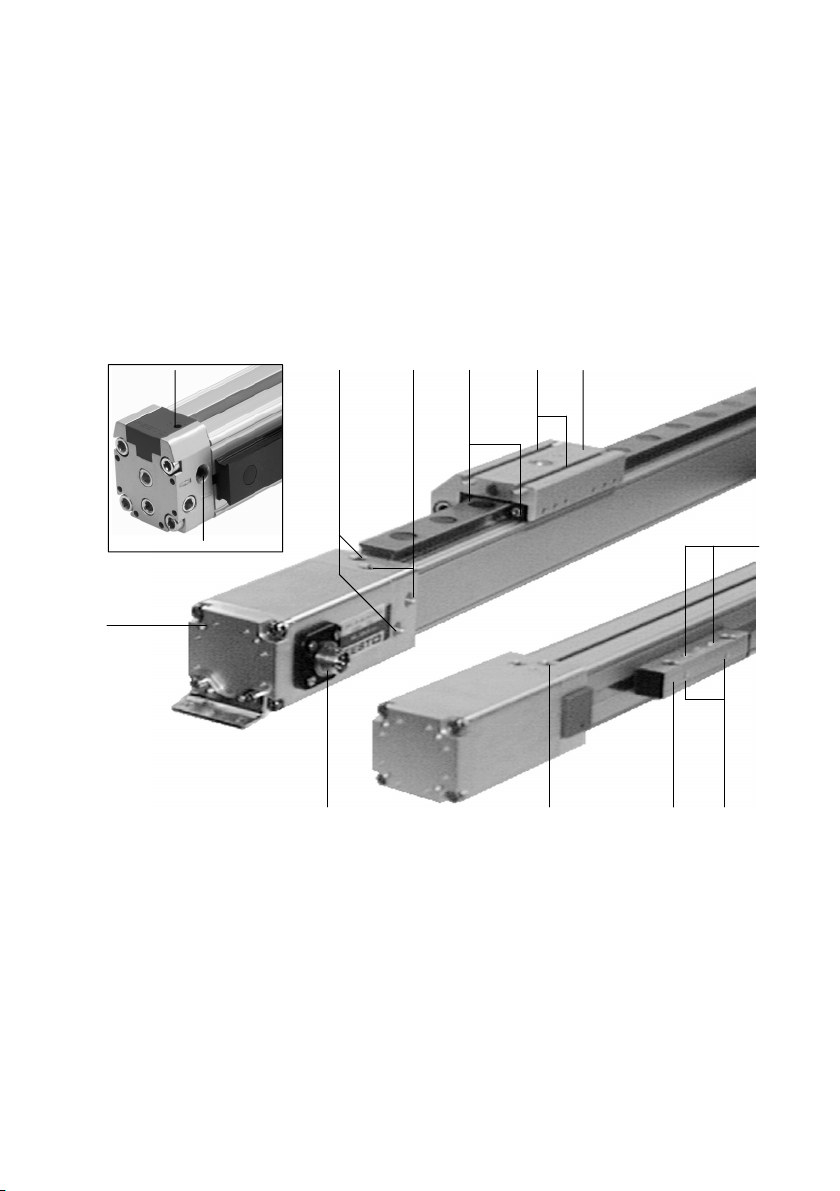
DGPI(L)−...−AI F
Pneumatisk linjärenhet DGPI(L)−Ū−AIFSvenska
1Komponenter och anslutningar
aB
aC
aA
1
Tryckluftsanslutning, indirekt
2 Tryckluftsanslutning, direkt
3 Smörjnippel för rullager
123
8 Medbringare
9 Hål för jordanslutning
aJ Mätsystemanslutning
4 5
9
6
7
8aJ
4 Spår för infästning av arbetslasten
5 Löpare
6 Hål för infästning av arbetslasten
7 Gänga för infästning av arbetslasten
Bild1
Festo DGPI(L)−...−AIF 0409a Svenska
aA Gänga för infästning av drivenheten
aB Justerskruv för ändlägesdämpning PPV
aC Tryckluftsanslutning för variant ...−D2
93
Page 94

DGPI(L)−...−AI F
2Funktion
Genom växelvis påluftning av tryckluftsanslutningarna sätts den inre löparen i
rörelse i röret. Genom en stel förbindelse rörs den yttre löparen med. Det spår som
krävs för detta omfattar ett bandsystem.
Med det integrerade mätsystemet kan löparens position definieras entydigt när
som helst.
3 Användning
Produkten är avsedd för pneumatisk positionering av massor.
Det integrerade mätsystemet (med CAN−axelgränssnitt) fungerar med:
ändlägesventil SPC11−MTS−AIF (Soft Stop) eller med
axelgränssnitt SPC−AIF−MTS med axel−controller SPC200.
4Transport och lagring
Observera den tunga vikten för DGPI(L)−....
Beroende på utförande väger DGPI(L)−...
över 80 kg.
94
Bild2
Festo DGPI(L)−...−AIF 0409a Svenska
Page 95

DGPI(L)−...−AI F
5 Förutsättningar för korrekt användning av produkten
Notera
Felaktig användning kan leda till felfunktioner.
S Säkerställ att det här kapitlets anvisningar alltid följs.
S Beakta varningar och anvisningar på produkten och i tillhörande
bruksanvisningar.
S Jämför gränsvärdena i denna
[%] [mbar][°C]
bruksanvisning med din aktuella
applikation (t.ex. krafter, moment,
temperaturer, massa).
Endast när belastningsgränserna beaktas
Bild3
kan produkten användas enligt gällande
säkerhetsdirektiv.
S Ta hänsyn till rådande omgivande
förhållanden.
Korrosiva omgivningar förkortar produktens livslängd (t.ex. ozon).
S Följ gällande lagar och bestämmelser.
S Använd produkten i originalskick utan några som helst egna förändringar.
S Avlägsna allt transportemballage såsom folier, övertäckningar och
kartongbitar.
Undantag: skydden över tryckluftsanslutningarna (för att förhindra
nedsmutsning).
Förpackningarna kan återvinnas (undantag: oljepapper = restavfall).
S Låt skyddskåporna av blå plast sitta kvar
på tillslutningslocken. Dessa skyddar
bandsystemets spännanordning mot yttre påverkan.
S Se till att tryckluften förbehandlas
LF−... LR−...
korrekt (se Tekniska data).
S Läs även dokumentationen till
styrsystemet (t.ex. SPC200, SPC11).
Bild4
Festo DGPI(L)−...−AIF 0409a Svenska
95
Page 96

DGPI(L)−...−AI F
6 Montering
Mekanisk montering
S Undvik skador på bandsystemet.
Skador på bandsystemet leder till läckage
och sänker prestandan hos DGPI(L)−....
S Se till att enheten monteras utan att
förspännas eller böjas.
Vid behov kan du använda profilfäste
(mittstöd) typ MUP−....
Bild5
Bild6
F
l l
F[N]
100000
10000
1000
100
500 1000 1500 2000 2500 3000
Bild7: Nödvändiga stödavstånd
96
l[mm]
ø80
ø63
ø50
F [N]
1000
500
0
1000
DGPI(L) −
32
25
F
40
1500
2000 2500
Festo DGPI(L)−...−AIF 0409a Svenska
F
3000
l [mm]
Page 97
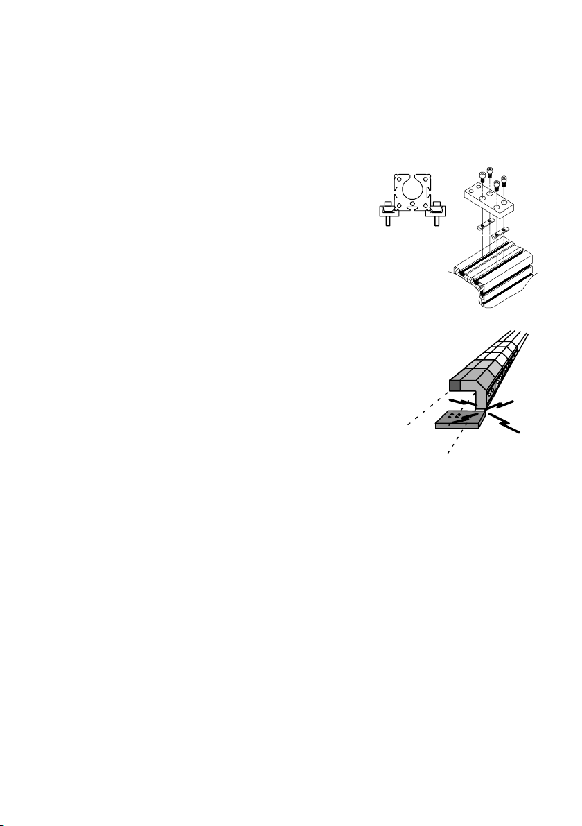
DGPI(L)−...−AI F
Montering av profilfästen MUP−...:
1. Placera profilfästena vid DGPI(L)−...
2. Dra åt fästskruvarna jämnt.
3. Se till att profilfästena befinner sig
enligt Bild8.
Vid dimensionerna 32 till 63 glider
spårmuttrarna i spåret på varje ställe
i profilen när de vrids.
utanför löparens rörelseområde.
Skjut löparen en gång längs hela slaget.
Ø 25
Ø 32 ...63
Bild8
Bild9
Festo DGPI(L)−...−AIF 0409a Svenska
97
Page 98

DGPI(L)−...−AI F
Montering av arbetslasten:
1. Välj ett monteringssätt:
DGPIL−...
1. Spårmuttrar NSTL−... vid löparen 4
2. Gängade hål och centreringselement
(se Tillbehör) vid löparen
Bild10: Monteringsmöjligheter för arbetslasten (se Bild 1)
DGPI−...
3. Hål 6 och gänga 7 i medbringaren
Mått för spårmuttrar NSTL−...
j 25 32 40 50 63
L 100 128 166 199 229
A 13 14 25 24 30
B 15 15 20 20 35
M M5 M5 M5 M8 M8
Bild11
Vid monteringsmöjlighet 2 måste
skruvarna vara kortare än de gängade
hålen.
Bild12
2. Placera arbetslasten så att tippmomentet
av kraften F parallellt med den rörliga
axeln och hävarmen a förblir lågt.
a
Bild13
F
Vid arbetslaster med egen styrning:
S Justera styrningarna av arbetslast och DGPI(L) exakt parallellt.
98
Festo DGPI(L)−...−AIF 0409a Svenska
Page 99

DGPI(L)−...−AI F
B
Pneumatisk montering
Vid montering i vertikalt eller snett läge:
Varning
Vid tryckfall faller den rörliga arbetsmassan ned. Okontrollerade rörliga massor
kan leda till person− eller sakskador (klämrisk).
(rörlig massa = löparens massa + arbetslastens massa)
S Läs även dokumentationen till styrsystemet (t.ex. SPC11/200). Där finns de
pneumatiska kopplingar med vilka fallet kan fördröjas.
Välj tryckluftsanslutningar.
Bild14
A
C
Förutom fabriksanslutningarna (A) finns
även alternativa anslutningar (B,
C). De är
försedda med låsskruvar.
Variant ...−D2 (med luftanslutning på båda sidor):
Här kan luftanslutning inte göras på bara en sida.
Vid slaglängder > 500 mm:
Vid styrning av DGPI(L)−... med hjälp av SPC11 eller SPC200 måste
tryckluftsmatning ske på båda sidor (variant D2).
Endast med inmatning på båda sidor garanteras optimal
dynamik.
Styrning av DGPI(L)−...:
S Använd proportionalventil MPYE−... för
hastighetsstyrning och positionering.
Bild15 visar en exempelkoppling.
Notera
Denna koppling lämpar sig inte för att
stoppa löparen vid ett tryckfall.
Bild15
5 ìm
Festo DGPI(L)−...−AIF 0409a Svenska
99
Page 100

DGPI(L)−...−AI F
4
5
3
6
Elektrisk montering
S Anslut jordanslutningen till jordpotentialen.
Kabeldiameter min 1,5 mm
2
Kabellängd max 10 m.
S Skruva i skruven med skärgänga (medföljer) i hålet för jordanslutning 9
(se Bild 1).
På så sätt garanteras kontakt trots anodoxiderskikt.
S Anslut mätsystemanslutningen till styrsystemet.
Endast originalkablar får användas (kontaktkonfiguration se Bild16).
Mätsystemanslutning
Stift Kontaktkonfi
guration
1 CAN−Low
2 CAN−High
6
1
n.c. = ledig (not connected)
Bild16
3
2
3 n.c.
4 n.c.
5 DC +24 V
6 0 V
Observera att permanentmagneten som sitter i kolven endast är avsedd för drift av
det integrerade mätsystemet.
Den är inte avsedd för cylindergivare med magnetisk aktivering.
100
Festo DGPI(L)−...−AIF 0409a Svenska
 Loading...