

Festo DFPI-100-***-E-P, DFPI-160-***-E-P, DFPI-200-***-E-P, DFPI-320-***-E-P Operating Instructions Manual
Page 1
Linear drive
DFPI−...−...−ND2P−E−P
Festo AG & Co. KG
Postfach
D−73726 Esslingen
++49/711/347−0
www.festo.com
(en) Operating instructions 740536
0811NH
Original: de
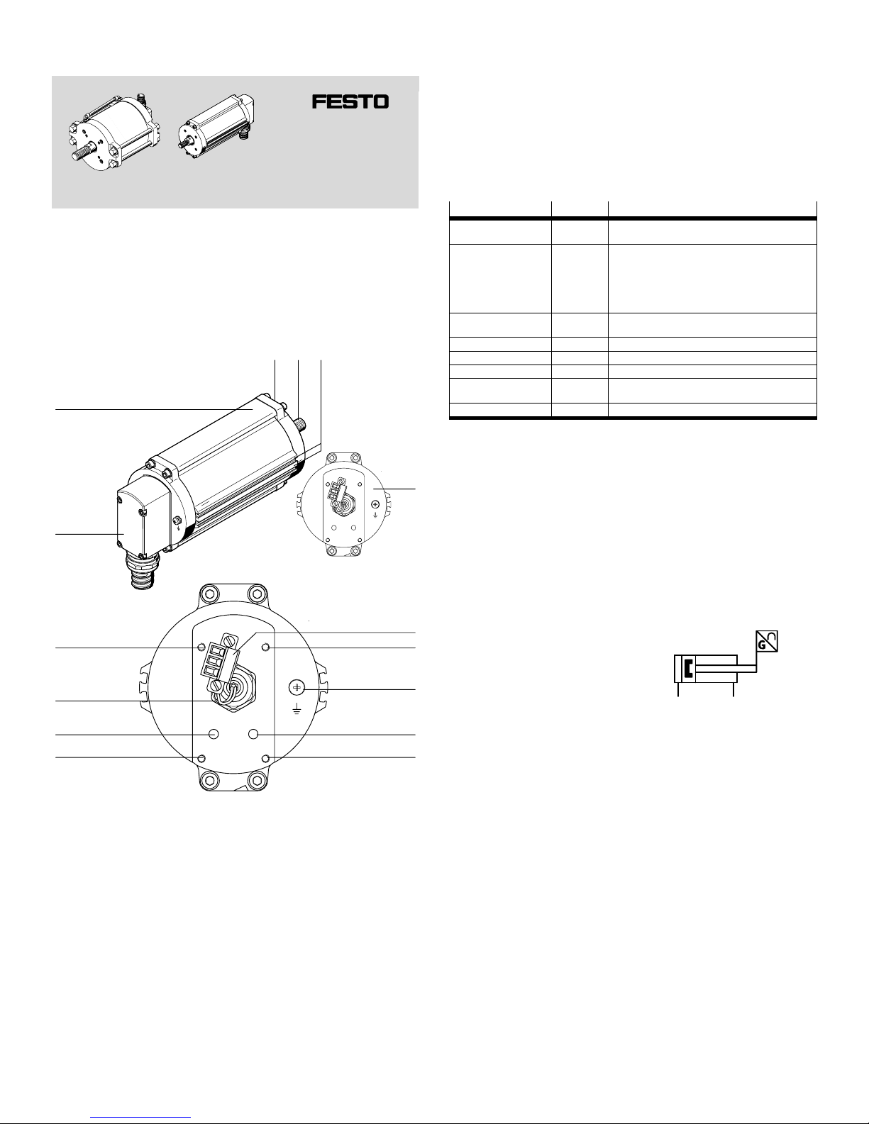
1 Operating elements and connections using the DFPI−100−... as an example
21
4
3
9
aJ
5
6
7
8
66
6
aA
aB
1 Mounting thread for adapter
(on rear, è Fig.4)
2 Piston rod with mounting thread
for coupling
3 Slot for proximity sensor
4 Shown without flange receptacle
5 Electrical connection
6 Thread for mounting the flange
receptacle
7 Earth terminal; position depends
on piston diameter of the drive
8 Pneumatic connection 4
(advance piston rod)
9 Pneumatic connection 2
(retract piston rod)
aJ Electric cable
(displacement encoder)
aA Flange receptacle; type depends
on piston diameter of the drive
aB Cylinder barrel; version depends
on piston diameter of the drive
Fig.1
2 Structure
The DFPI−...−...−ND2P−E−P is an electropneumatic linear drive consisting of:
a double−acting pneumatic cylinder with
integrated displacement encoder (potentiometer) for determining the actual
position.
The displacement encoder supplies an analogue signal proportional to the
displacement in the form of a voltage (voltage divider).
If necessary, proximity switches can be installed in the slots (è Fig.1 3 ) in order
to provide binary interrogation of positions.
The electric and pneumatic connections are protected against external mechanical
influences by a rugged flange receptacle.
Characteristics Type code Description
Type DFPI Double−acting pneumatic drive for process
automation with integrated displacement encoder
Size of servo drive 100
125
160
200
250
320
Piston diameter can be selected in steps;
dimensions in [mm]
Stroke Ū
(40 Ū 990)
Stroke length freely selectable in the range
from 40 to 990; dimension in [mm]
Cushioning N No cushioning
Displacement encoder D2 Integrated analogue displacement encoder
Method of measurement P Potentiometer
Controller attachment
position
E External (no controller integrated)
Connection type P Protected pneumatic connections
Fig.2
The following characteristics of the linear drive are dependent on the piston
diameter, and may differ from the depiction in Fig.1:
Position of the earth terminal (è identification on product)
Shape of the cylinder barrel
Shape of the flange receptacle
In addition, for linear drives with a piston diameter ţ 200mm the compressed air
supplied from one side is fed via an unprotected line parallel to the cylinder barrel.
Tie rod screws are used to mount the cylinder end cap.
For linear drives with a piston diameter Ţ 200mm the compressed air is fed inter
nally. The cylinder end caps are screwed to the housing.
3 Function
Pressurising and depressurising of the
cylinder chamber causes the piston rod
connected to the piston to move to and
fro. The integrated displacement
encoder transmits the current position
to the higher−level system as an
analogue signal.
Fig.3
The processing valve (e.g. slide plate, penstock shut−off valve) , which is connected
via a coupling, opens or closes depending on the motion of the piston rod. The
cross−sectional area of the piston rod differences of force between forward stroke
and return stroke (è www.festo.com/catalogue).
4 Application
The designated use of the DFPI linear drive is to drive linearly actuated processing
valves in process systems for example slide valve actuators and penstock
shut−off valves. It is suitable for use in the process industry in the area of:
water,
sewage,
industrial process water,
silage and
bulk goods technology.
The stroke length of the drive is generally at least equal to the nominal diameter of
the valves and fittings, so that the slide valve actuator can be opened and closed
completely using the DFPI.
The product is tailored to the requirements of the process industry
(è catalogue www.festo.com/catalogue).
Page 2
5 Transport and storage
Warning
Danger or crushing! Danger of shearing!
The DFPI can weigh up to about 86 kg, depending on the product version.
Body parts can be crushed or cut off if the product falls down.
· For product versions weighing more than 12 kg, always use suitable load−
carrying equipment in order to handle the product safely during transport and
assembly.
Ensure the following storage conditions:
Short storage periods in cool, dry, shaded and corrosion−protected locations.
6 Conditions for the safe use of the product
Fitting and commissioning is to be carried out only by qualified personnel in
accordance with the operating instructions.
Please note
Improper handling can result in malfunctions.
· Make sure that all the instructions in this chapter are observed. The product
will then function correctly and reliably.
Please note
Lateral forces on the piston rod can damage the piston rod bearing of the DFPI.
· Make sure that there are no lateral forces acting on the piston rods.
Please note
Continuous operation at the limits of the specified ambient temperature and
work frequency can reduce the service life of the drive.
· Use lubricated compressed air for continuous operation under extreme
conditions. The oil must be chemically inert (chemically stable) and must not
carbonize.
· Compare the maximum values specified in these operating instructions with
your actual application (e.g. pressures, forces, torques, masses, speeds,
temperatures). The product can only be used in accordance with the relevant
safety guidelines if the maximum loading limits are observed.
· Ensure that all applicable national and local safety laws are adhered to.
· Remove the packing except for the adhesive labels on the compressed air
connections (to prevent dirt). The packing is intended for recycling (except for:
oiled paper = other waste).
· Take into consideration the ambient conditions at the location of use. Corrosive
environments reduce the service life of the product.
· Unauthorized product modification is not permitted.
· The product is not a safety component and must only be used as designated.
· Protect the device from fluctuations in pressure and excess operating tempera
ture. Use control valves for regulating pressure and excess pressure.
· Ensure that the compressed air is properly prepared è Technical specifica
tions in chapter 13).
· Use only non−lubricated compressed air under normal conditions. The product
has an initial lubrication which suffices for the complete service life. Using lubri
cated compressed air flushes out the initial lubrication. The product may then
only be operated with lubricated compressed air.
· Make sure that cut−off tube ends are cut off square and are free of burrs. This
way you prevent damage to internal O−rings of the DFPI when the compressed
air tubes are inserted.
· Please select the appropriate accessories, for example protective conduit and
electric cable, from our catalogue www.festo.com/catalogue.
7 Installation
Please note
If proximity sensors are used: Ferrous materials (e.g. steel parts and sheets) in
the immediate vicinity of proximity switches can result in unwanted switching
signals. When linear drives are installed too close to each other, a cylinder
magnet can trigger switching of the proximity switch on the neighbouring linear
drive.
· During assembly, maintain the required minimum distances from ferrous
materials. The required distances must be determined during assembly for
each specific case!
· When installing more than one linear drive, make sure that the area of effect
of each cylinder magnet does not affect any proximity switches of neigh
bouring linear drives.
If there are high medium temperatures in the tubing and in the processing valve:
· Use a heat−insulated coupling extension.
7.1 Mechanical assembly
The linear drive has a mounting hole pattern to DIN 3358. This is used for screwing
the linear drive to the processing valve or penstock shut−off valve. It can be fitted in
any position.
·If necessary, use the appropriate adapters
(è catalogue www.festo.com/catalogue).
· Mount the DFPI with 4 screws.
The piston rod has a male thread for mounting the slide plate.
·If necessary, use the appropriate adapters
(è catalogue www.festo.com/catalogue).
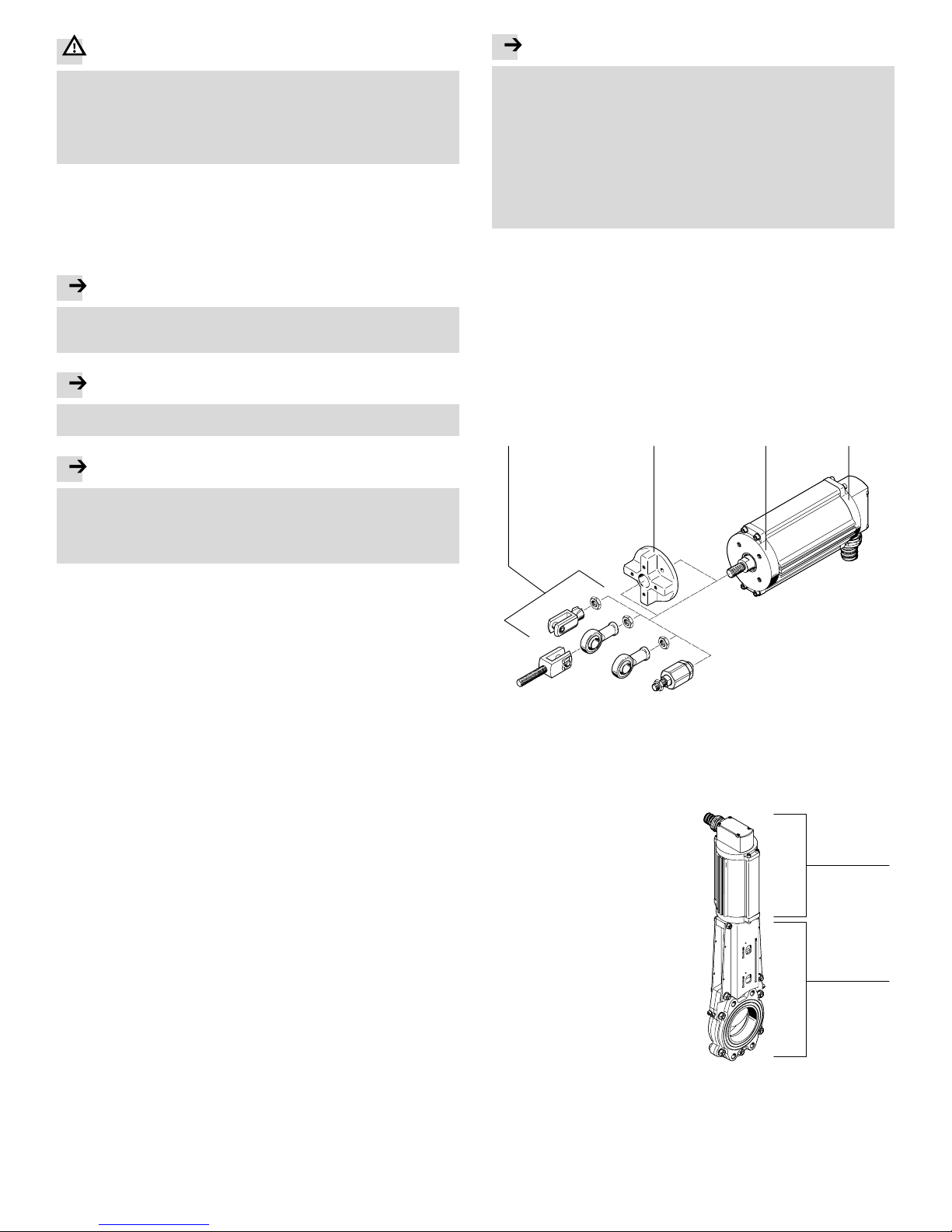
Fig.4
2134
1 Adapter for mounting the slide
plate examples
2 Adapter DAPZ (for adapting the
hole pattern by 45°)
3 Bearing cap with mounting thread
(4) for installation on slide valve
actuator with hole pattern to
DIN3358
4 End cap
The illustration to the right shows an
example for the mechanical connection
of a DFPI (è Fig.5 1 ) to a slide valve
(è Fig.5 2 ). Observe the following
during installation:
· Install the DFPI in such a way that
there are no lateral forces acting on
the piston rod bearings.
· Install the DFPI in such a way that
the required mode of operation for
opening and closing the processing
valve or penstock shut−off valve is
implemented.
Fig.5
1
2
Page 3
When using additional proximity
switches:
· Place the proximity switches in the
corresponding grooves. Cover rails
over the grooves fasten the cables
and protect them against dirt.
· During assembly, maintain the
required minimum distances from
ferrous materials.
Fig.6
7.2 Electrical installation
Warning
· Use only power units which guarantee reliable electrical isolation of the
operating voltage as per IEC/DIN EN 60204−1.
Take into account also the general requirements for PELV circuits as per
IEC/DIN EN 60204−1.
Please note
Installation errors can damage the electronics or cause faults.
· Make sure that the length of the displacement encoder cable does not exceed
the permissible length of 30 m.
· Connect the earth terminal (Fig.1 7 ) with the earth potential with low resis
tance (short cable with large cross−section) tightening torque 5 Nm ±10 %.
·To transmit analogue signals, use only screened cables with twisted pairs.
Attach the cable screening at one end to the higher−level system.
· Use an electrical connecting cable with a nominal outside diameter of 8 mm.
· Observe the pin assignment (è Fig.8). The displacement encoder may only
be used as a voltage divider not as a variable resistor.
The electrical connection is covered by the flange receptacle (è Fig.1). To perform
electrical installation you will have to dismantle the flange receptacle.
The structure of the flange receptacle and the cable conduit fitting are shown in
the following illustration:
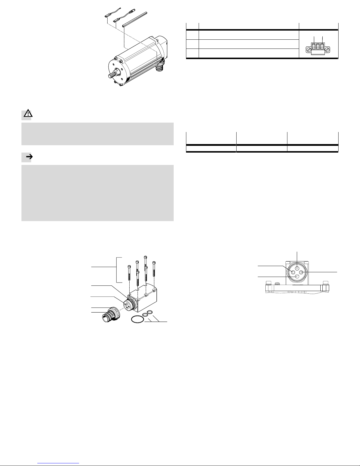
1 Mounting screws
tightening torque è Fig.9
2 Seals (O−rings)
3 Protective conduit
can be pulled on using
assembly tool
4 Cable conduit fitting
tightening torque 15 Nm
5 Seal insert
6 Threaded connector
tightening torque 15 Nm
Fig.7
1
2
3
4
5
6
1. Loosen the mounting screws of the flange receptacle (è Fig.7 1 ) and carefully
remove the flange receptacle.
2. Loosen the cable conduit fitting (è Fig.7 4 ).
3. Stick the electrical connecting cable through the passage of the seal insert of
the flange receptacle (è Fig.10 3 ).
4. If necessary, loosen the socket strip of the electrical connection, which is
fastened with two screws.
5. Use the wire end sleeves suitable for the connection and wire the socket strip
according to the pin assignment (è Fig.8) tightening torque 0.2 Nm +20 %.
The 3−pole connection is used to supply power to the integrated displacement
encoder and to make the sensor signal available.
Pin Assignment
1)
Connection
1 Power supply
3
1
2 Actual value, signal
3 Power supply +
1) Maximum permissible supply voltage è technical specifications in chapter 13
Fig.8
6. Carefully plug the wired−up socket strip onto the connector.
7. Refasten the socket strip with the two screws
tightening torque: 0.5 Nm ±10 %.
8. Reinstall the flange receptacle. When doing so, make sure that the seals and
O−rings are correctly seated.
9. When tightening the mounting screws of the flange receptacle, observe the
tightening torque (è Fig.9).
Tightening torque of the mounting screws of the flange receptacle
Version DFPI−100−...−E−P to
DFPI−160−...−E−P
DFPI−200−...−E−P to
DFPI−320−...−E−P
Tightening torque [Nm] 2.7 ±10 % 6 ±10 %
Fig.9
7.3 Installing the pneumatic system
· Use standard O.D. pneumatic connecting tubes with an outside diameter of
8 mm. The pneumatic tube PNU−8x1,25 from Festo is suitable, for example.
· Check to see if closed−loop controlled non−return valves type HGL−... are
necessary.
This way you can prevent the moveable mass sliding down if there is a drop in
pressure when the product is fitted in a vertical or sloping position.
Connection is via the flange receptacle (è Fig.10). This provides push−in
connectors for the pneumatic system and a through−hole for the electric cable.
Connect the tubing of the DFPI as follows:
1. If necessary, loosen the cable conduit fitting (è Fig.7 4 ).
2. Connect the tubing of the DFPI to the compressed air connections (è Fig.10).
To do this, stick the individual tubes into the corresponding holes in the seal
insert as far as they will go (è including Fig.7 5 and Fig.10).
1 Dowel pin
2 Pneumatic connection 2:
retract piston rod
3 Passage for electric cables
4 Pneumatic connection 4:
advance piston rod
Fig.10
1
2
3
4
Air supply at connection 2 (è Fig.10 2 ): piston rod retracts
(open processing valve)
Air supply at connection 4 (è Fig.10 4 ): piston rod advances
(close processing valve)
3. Retighten the cable conduit fitting (è Fig.74 ) on the flange receptacle
tightening torque è Fig.7 4.
8 Commissioning
The product is ready for operation as soon as it is fitted and electrically and
pneumatically connected.
· Make sure that the operating conditions lie within the permitted ranges
(Technical specifications è chapter 13).
· Make sure that a slide plate (processing valve) mounted on the linear drive can
be positioned without hindrance.
·If necessary, adjust the linear drive adapter fitted on the piston rod. This setting
serves for optimising the opening or closing reaction of the connected
processing valve or penstock shut−off valve.
· Slowly pressurise the linear drive.
For slow start−up pressurisation use soft−start valve type HEL.
·At first, select a slow positioning speed.
Page 4
9 Operation
Warning
Uncontrolled fast moving parts can cause injury to people in the vicinity of the
DFPI.
· Make sure that:
no−one can reach into the operating direction of the moving components
(e.g. use a protective grid)
there are no objects within the positioning path.
It should not be possible to touch the DF PI until the mass has come to a
complete stand.
10 Care and maintenance
If used as designated in the operating instructions, the device will be free of
maintenance.
11 Dismantling and repairs
Make sure that the following sources of energy are switched off:
electrical power supply
the compressed air supply
1. Remove the slide plate from the piston rod.
2. Remove the screws on the flange of the processing valve or penstock shut−off
valve.
3. Remove the drive (if necessary including mounting adapter and coupling
extension).
Recommendation: Return the product to our repair service for overhaul.
This ensures that the necessary fine adjustments and checks will be given
particular attention.
Information about spare parts and auxiliary means è www.festo.com/spareparts.
12 Troubleshooting
Fault Possible cause Remedy
Piston rod does not move in
the desired direction
Compressed air tubes
interchanged
Correct the tubing
the desired direction
Displacement encoder cable
incorrectly connected on
positioning controller or on
DFPI (e.g. connections on pin 1
and pin 3 interchanged).
Correct the connection
Fig.11
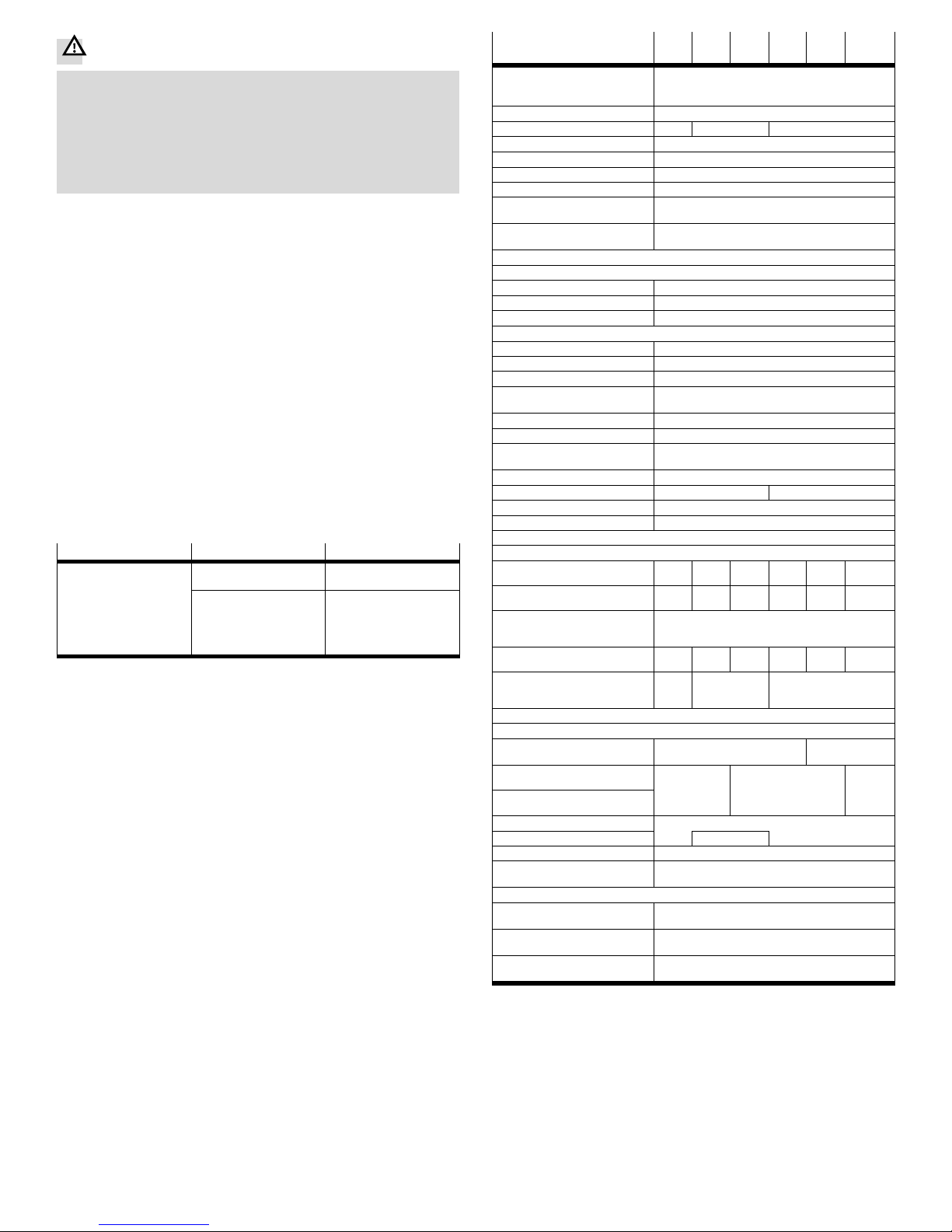
13 Technical specifications
DFPI−...−...−ND2P−E−P −100−Ū−125−Ū−160−Ū−200−Ū−250−Ū−320−
Ū
Based on standard
(connection to valves and
fittings)
DIN 3358
Type of mounting On flange to DIN 3358
Flange hole pattern F07 F10 F10, F14
Constructional design Piston rod, cylinder barrel
Cushioning None
Assembly position As desired
Method of operation Double−acting
Position sensing For position switched integrated with displacement
encoder
Measuring principle of
displacement encoder
Potentiometer
Resistance value of displacement encoder (on the T.E.P.) as a function of the stroke length
1)
˚ 290 mm [k] 5
, 290 mm to 590 mm [k] 10
, 590 mm to 990 mm [k] 20
Pneumatic connection Standard O.D. for tube outer ∅ 8 mm
Operating pressure [bar] 3 Ū 8
Nominal operating pressure [bar] 6
Operating medium Filtered compressed air, grade of filtration 40 m,
lubricated or unlubricated
Max. operating voltage DC [V DC] 15
Max. line length [m] 30
Protection class IP65, IP67 in assembled state to IEC60529;
IP69K, NEMA 4 in assembled state
Stroke [mm] 40 Ū 990
Stroke reserve [mm] 3 4
Ambient temperature [°C] 20 Ū +60
Outdoor use C1 use in weather−protected areas
Product weight
Basic weight
with 0 mm stroke
[g] 3476 5530 6529 13 946 22 569 35 359
Additional weight
per 10mmstroke
[g] 80 145 159 187 325 399
Additional weight
of displacement encoder
per 10 mm
[g] 2
Moving load
with 0 mm stroke
[g] 1228 1944 2250 4722 7059 11417
Additional weight
of moving load per
10 mm stroke
[g] 27 52 87
Material
Cylinder barrel Wrought aluminium alloy,
anodised
High−alloy,
stainless steel
Cap (end cap) Wrought
aluminium alloy,
Die−cast aluminium,
painted
Wrought
aluminium
Bottom cap (bearing cap)
aluminium alloy
,
anodised
painted
aluminium
alloy,
anodised
Piston rod High−alloy stainless steel
Screws Steel
Seals Nitrile rubber
2)
Note on materials Contains paint wetting impairment substances,
conforms to RoHS
Vibration resistance
to DIN/IEC 68 par ts 2−6
Tested to severity level 2
Continuous shock resistance
to DIN/IEC 68 par ts 2−82
Tested to severity level 2
CE mark (see declaration of
conformity è www.festo.com)
To EU EMC directive
1) T.E.P. = theoretical electrical path
2) For piston diameter 100 mm also thermoplastic polyurethane elastomer
Fig.12
 Loading...