

Page 1
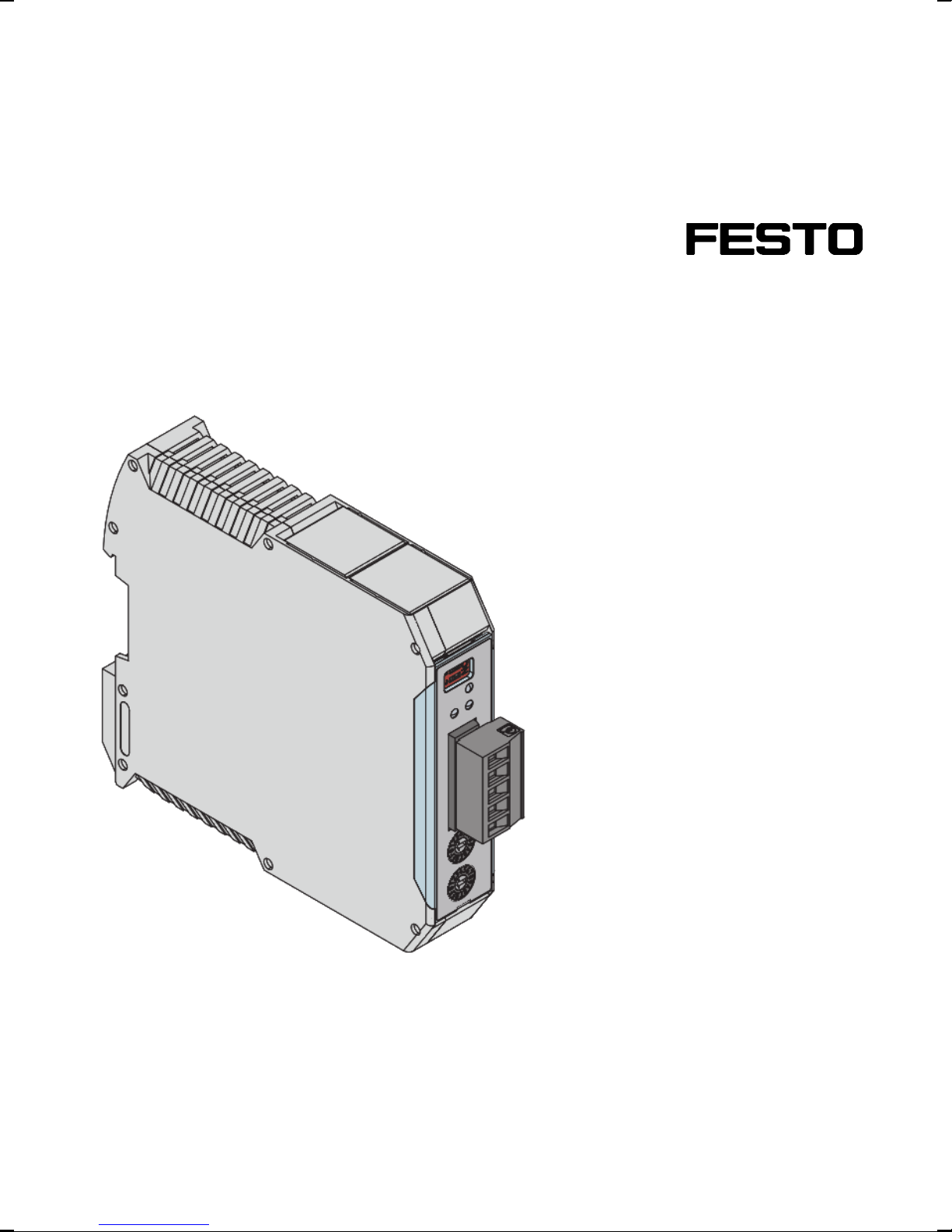
Extension module
CMGA-E1-DN
Description
Installation manual
Extension module
DeviceNet
761726
1201NH
Page 2

CMGA-E1-DN
Translation of the original instructions
GDCP-CMGA-E1-DN-EN
DeviceNet
®
and RSNetWorx®are registered trademarks of the respective trademark owners in cert ain
countries.
Status: H B-37350-810-57-01E-DE
Identification marking of dangers and instructions on how to avoid them:
Warning
Dangers which can lead to death or serious injuries.
Caution
Dangers which can lead to light injuries or to serious material damage.
Other symbols:
Note
Material damage or loss of function.
Recommendation, tip, reference to other documentation
Necessary or useful accessories
Information on environmentally friendly use
Text designation:
• Activities which can be carried out in any sequence.
1. Activities which should be carried out in the specified sequence.
– General lists
2 Festo – GDCP-CMGA-E1-DN-EN – 1201NH
Page 3

CMGA-E1-DN
Table of contents – CMGA-E1-DN
1 Important note 4...........................................................
2 Safety regulations 4........................................................
2.1 Installation and c ommissioning 4..............................................
2.2 User instructions 4..........................................................
2.3 Intended utilization 4........................................................
2.4 Operation and service 4......................................................
2.5 Scope of delivery 5..........................................................
3 Description of function 5.....................................................
4 Commissioning 6...........................................................
4.1 Procedure 6...............................................................
4.2 Project engineering 6........................................................
4.2.1 Linking in the electronic data sheet file 6...................................
4.2.2 Linking into the network diagram 7.......................................
4.2.3 Setting CMGA-E1-DN 8.................................................
4.2.4 Configuration of the DeviceNet scanner 9..................................
4.2.5 Linking into RSLogix 5000 10.............................................
4.2.6 Validation of the CMGA-E1-DN data 11.....................................
4.3 Device settings 12...........................................................
4.3.1 Address switch 12......................................................
4.3.2 Coding switch 13.......................................................
4.4 Diagnostics 13..............................................................
4.5 Configuration of the user data 14...............................................
4.6 Modification / handling changes to the device 14..................................
5 Maintenance 14.............................................................
5.1 Replacement of a module 14...................................................
6Technicaldata 15............................................................
6.1 Environmental conditions 15...................................................
6.2 Characteristic data 15........................................................
7 Pin allocation 15............................................................
Festo – GDCP-CMGA-E1-DN-EN – 1201NH 3
Page 4

CMGA-E1-DN
1 Important note
Definition of individual target groups
– Project engineers for safe drive systems: engineers and technicians
– Assembly, electrical installation, maintenance and replacement of devices: company electricians
and service technicians
– Commissioning, operation and configuration: technicians and engineers
2 Safety regulations
2.1 Installation and commissioning
– Do not install or operate damaged pro ducts. Please report any damage immediately to the forward-
ing agent responsible.
– Installation work, commissioning and service work on the device may only be performed by qualified
electrical personnel with relevant knowledge of the acc ident prevention regulations.
– The applicable regulations, and any other special safety regulations relevant to the particular ap-
plication, must be strictly observed.
2.2 User instructions
– Only install the module and put it into operation if you are fully familiar with the applicable regula-
tions on working safety and with the operating instructions of the CMGA-B1 basic modules.
2.3 Intended utilization
– The module may only be used as a “slave” mo dule in a DeviceNet environment in a ccordance with
the EN 50170 standard.
– CMGA-E1-DN is not permitted to be used for safety-related reactions.
2.4 Operation and service
– The module must always be de-energized before installation and removal, or before disconnecting
signal lines or power supply cables.
– When installing or removing the module, appropriate measures must be taken to prevent electro-
static discharge to the externally arranged terminal and plug connections.
4 Festo – GDCP-CMGA-E1-DN-EN – 1201NH
Page 5

CMGA-E1-DN
2.5 Scope of delivery
The scope of delivery includes:
– Extension module CMGA-E1-DN
The EDS file with CMGA icon and the installation handbooks can be found on the CD ROM
GSPF-CMGA-BS... or under www.festo.com.
3 Description of function
The CMGA-E1-DN enables the user to transmit telegrams (diagnostic telegram such as
CMGA-B1-M2-L2-A0) via DeviceNet. A maximum of 2 CAN telegrams can be forwarded.
The module should be parametrised as a DeviceNet participant (slave).
The DeviceNet baud rates of 125 kbps, 250 kbps and 500 kbps can be set via the front address switch.
The size of the output information is 16 byte.
The CMGA-E1-DN must must be connected with one or several basic modules (CMGA-B1-M...) via a
plug-in c onnector on the back wall.
The DeviceNet plug connection must be made in accordance with the installation regulations of the
ODVA.
CMGA-B1-M1-L1-A0 CMGA-E1-DN
Fig. 1 Example of a configuration of CMGA-B1-M2-L2-A0 with CMGA-E1-DN
Festo – GDCP-CMGA-E1-DN-EN – 1201NH 5
Page 6
CMGA-E1-DN
4 Commissioning
4.1 Procedure
Commissioning must only be performed by qualified personnel! Strictly follow the safety regulations
when commissioning!
The following example shows a commissioning with RSNetWorx.
4.2 Project engineering
First copy the supplied electronic data sheet file with icon into the corresponding Rockwell program
directory.
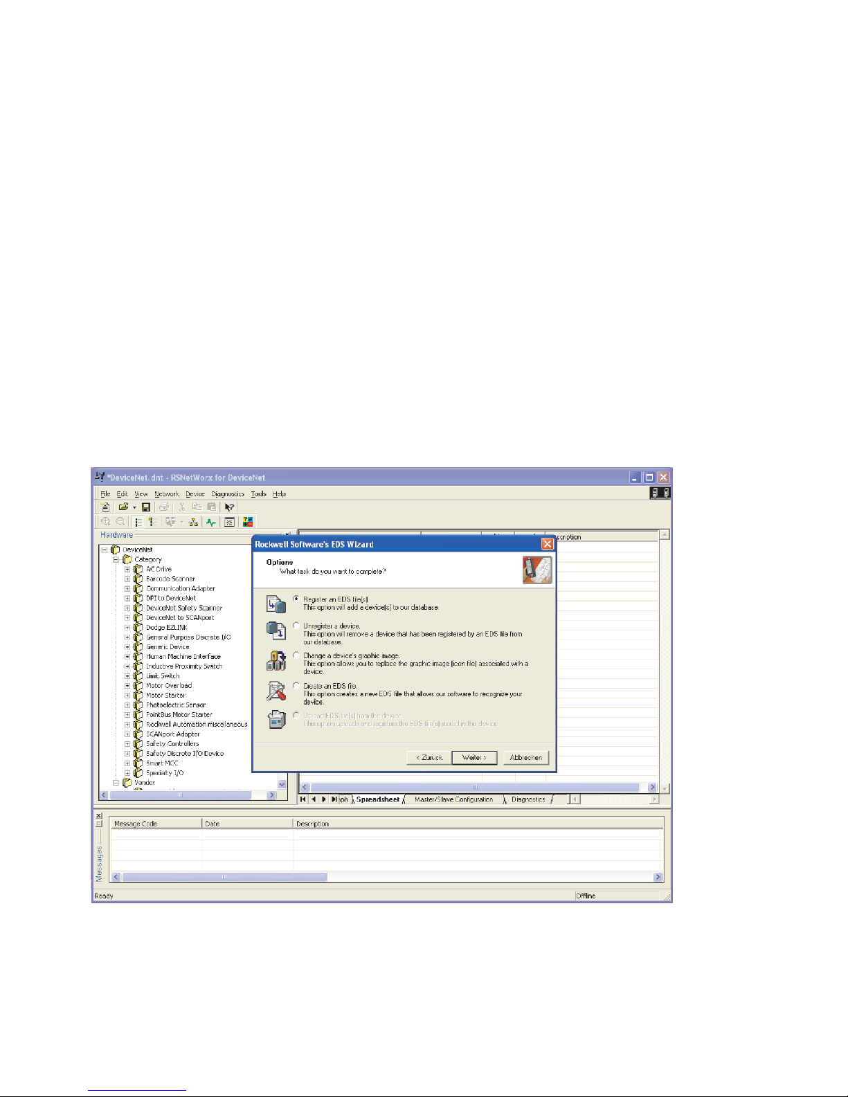
4.2.1 Linking in the electronic data sheet file
Electronic data sheet files can be linked in, removed or assigned to icons in the menu Tools > Electronic
Data S heet Wizard.
Fig. 2 Electronic Data Sheet Wizard
6 Festo – GDCP-CMGA-E1-DN-EN – 1201NH
Page 7
CMGA-E1-DN
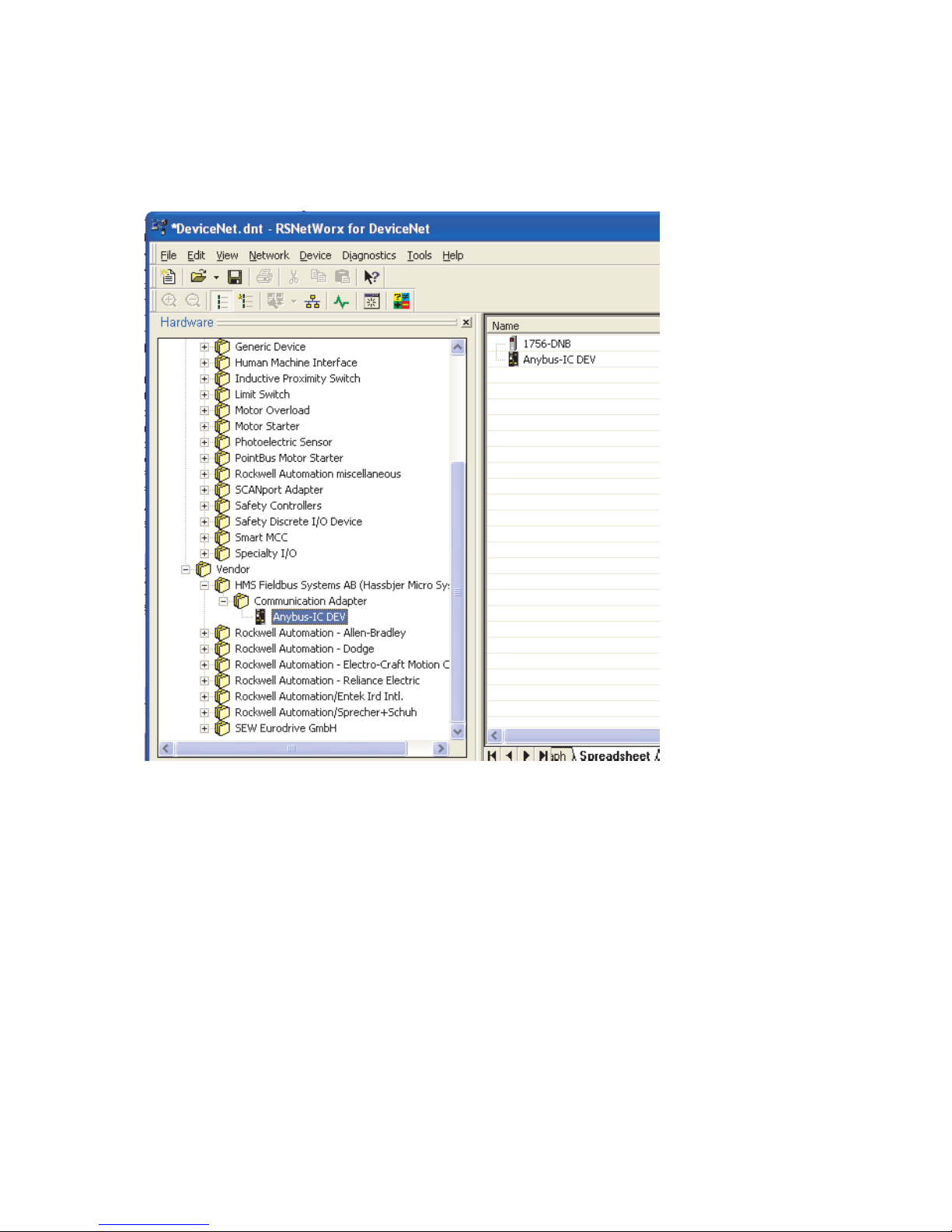
4.2.2 Linking into the network diagram
Thedevice“Anybus-IC DEV” can be dragged into the diagram by “drag and drop” in the hardware menu
under Vendor.
Fig. 3 Linking into the network diagram
Festo – GDCP-CMGA-E1-DN-EN – 1201NH 7
Page 8

CMGA-E1-DN
4.2.3 Setting CMGA-E1-DN
By double clicking on “Anybus-IC DEV”, the following information can be displayed.
The only setting which must be made here is the issuing of the bus address (node).
Fig. 4 Settings
8 Festo – GDCP-CMGA-E1-DN-EN – 1201NH
Page 9

CMGA-E1-DN
4.2.4 Configuration of the DeviceNet scanner
The following settings must be made by selecting the scanner (here: 1756-DNB).
The I/O parameters must be selected in the Scanlist menu.
Fig. 5 Configuration of the DeviceNet scanner scanlist
In the Input menu the input information (16 byte cyclic) must be “mapped” in the address range of the
scanner.
Fig. 6 Configuration of the DeviceNet scanner address range
When all settings have been made, the network diagram can be saved.
Festo – GDCP-CMGA-E1-DN-EN – 1201NH 9
Page 10
CMGA-E1-DN
4.2.5 Linking into RSLogix 5000
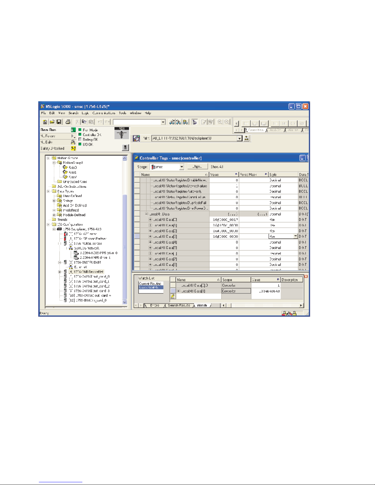
In order to be able to validate the scanner data (1756-DNB), the scanner must be linked into the
“I/O configuration”.
By selecting the module the saved network diagram can be loaded in the “Module Properties” window
in the RSNetWorx menu.
Fig. 7 Linking into RSLogix 5000
10 Festo – GDCP-CMGA-E1-DN-EN – 1201NH
Page 11
CMGA-E1-DN
4.2.6 Validation of the CMGA-E1-DN data
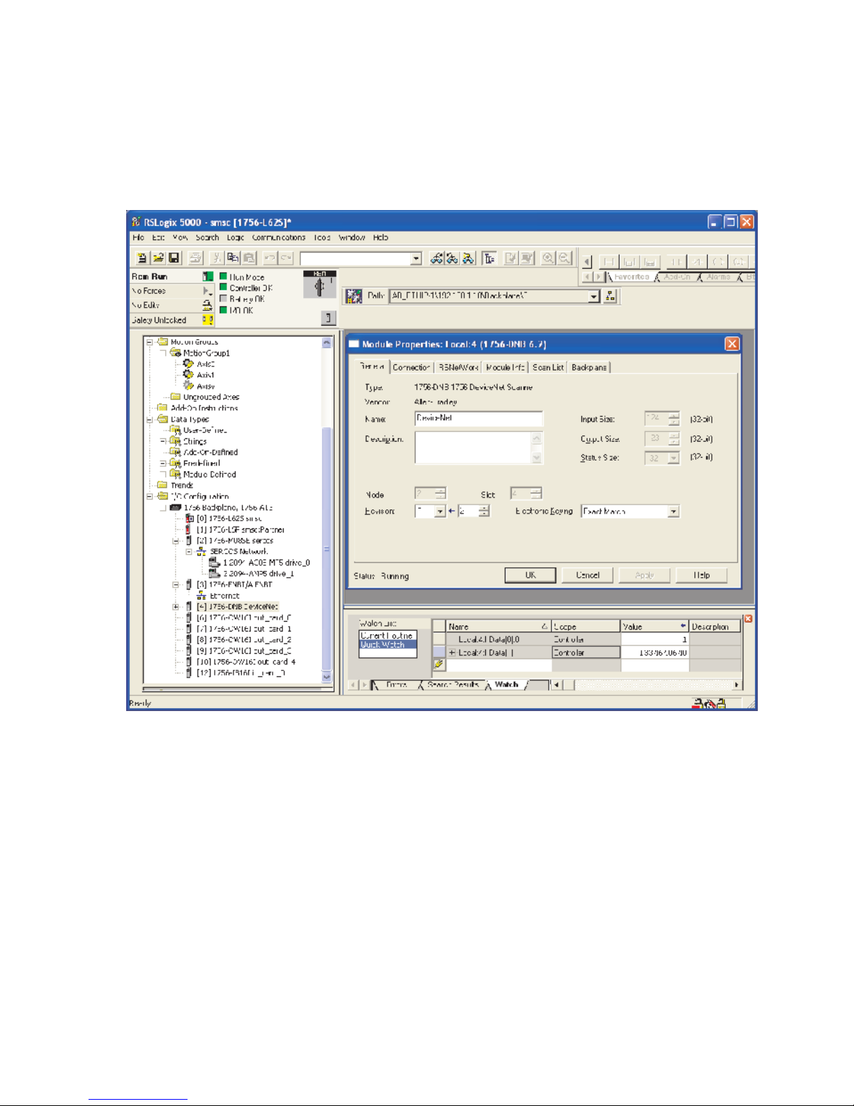
One can enable the Controller Tags window in the Logic menu.
Before the data can be validated, the DeviceNet scanner must be set in the “RUN” mode. This is done
by setting the bit “Local:4:O.CommandRegister.Run”.
Fig. 8 Validation of the CMGA-E1-DN data
Festo – GDCP-CMGA-E1-DN-EN – 1201NH 11
Page 12
CMGA-E1-DN
4.3 Device settings
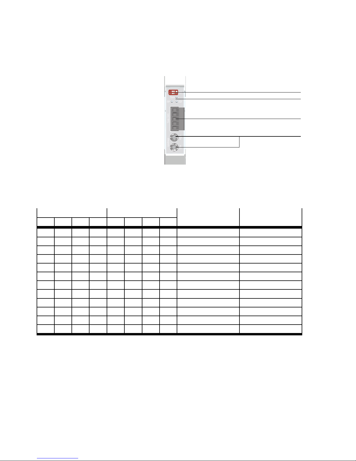
Thefollowingcanbesetonthefrontofthemodule:
1 Coding switch for Bus
termination
2 Diagnostics LEDs
3 Fieldbus plug connector
4 DeviceNet address switch
Fig. 9 Front of CMGA-E1-DN
4.3.1 Address switch
With these switches one can set the bus address ( up to max. 63) and the DeviceNet baud rate.
The entry is made in hexadecimal.
1
2
3
4
Address HIGH
Address LOW Baud rate Node ID
B7 B6 B5 B4 B3 B2 B1 B0
– – 0 0 0 0 0 0 – 0
– – 0 0 0 0 0 1 – 1
– – 0 0 0 0 1 0 – 2
– – 0 0 0 0 1 1 – 3
– – … … … … … … – …
– – 1 1 1 1 0 1 – 61
– – 1 1 1 1 1 0 – 62
– – 1 1 1 1 1 1 – 63
0 0 – – – – – – 125 kbps –
0 1 – – – – – – 250 kbps –
1 0 – – – – – – 500 kbps –
1 1 – – – – – – Auto baud Not supported
Tab. 1 DeviceNet address and baud rate
12 Festo – GDCP-CMGA-E1-DN-EN – 1201NH
Page 13
CMGA-E1-DN
e.g. baud rate 125 kbps:
– e.g. baud rate address: 5: ADDR HIGH = “0”
ADDR LOW = “5”
– e.g. baud rate address: 46: ADDR HIGH = “2”
ADDR LOW = “E”
e.g. baud rate 250 kbps:
– e.g. baud rate address: 5: ADDR HIGH = “4”
ADDR LOW = “5”
– e.g. baud rate address: 46: ADDR HIGH = “6”
ADDR LOW = “E”
4.3.2 Coding switch
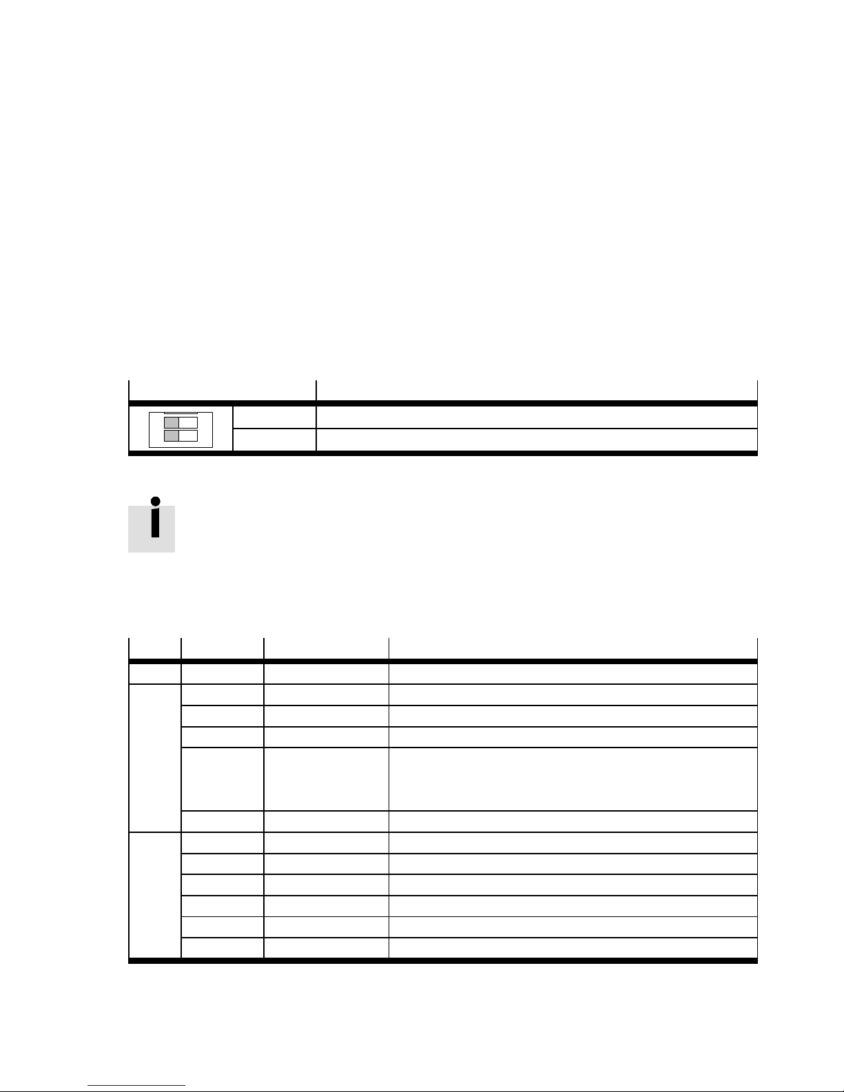
Terminating resistor for CANbus connection:
Coding switch
1
2
ON
switch 1 120 Ohm terminating resistor on back wall of CAN
switch 2 120 Ohm terminating resistor on 2nd CAN interface via SUB-D socket
Description
Tab. 2 Coding switch terminating resistor
Note:
• If DeviceNet is being used, both switches are to be set to “OFF”.
4.4 Diagnostics
LED Colour Mode Description
RUN Green “flashing” Module OK
DP Green “permanent” DeviceNet connection active
Green “flashing” Bus in IDLE mode
Red “flashing”??? Fault in the device (contact manufacturer)
Red “flashing” Time out connection
24V bus supply voltage is missing
Faulty setting of bus address or baud rate
Red/green “alternating” In self test mode
XB Green “permanent” Processing OK
Green “flickering” Missing CA N telegram
Green “flashing” AutoBaud processing
Red “permanent” Fault in the device (contact manufacturer)
Red “flashing” Resettable error message
Red “alternating” In self test mode
Tab. 3 LED display
Festo – GDCP-CMGA-E1-DN-EN – 1201NH 13
Page 14
CMGA-E1-DN
4.5 Configuration of the user data
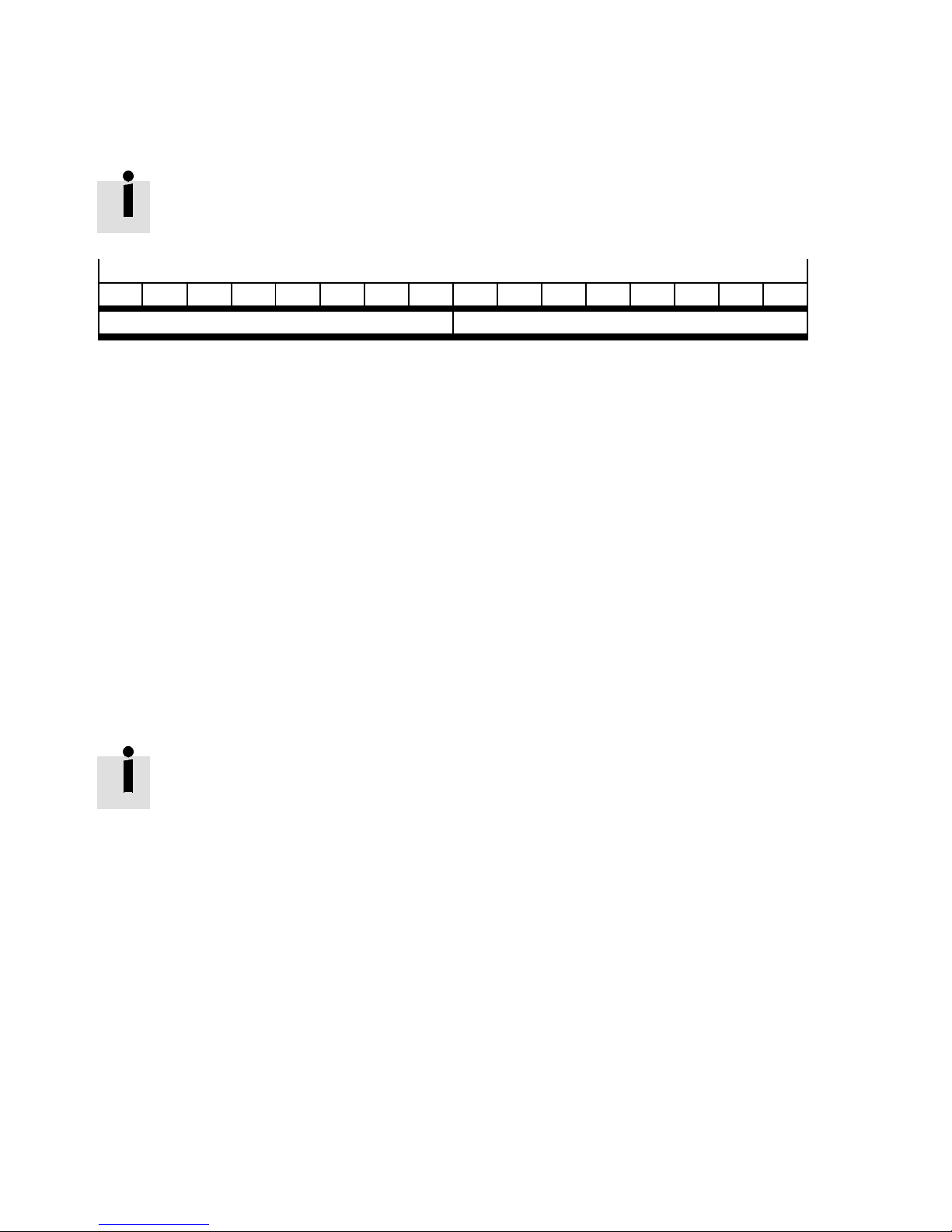
Configuration of the internal data frame, see installation handbook for
GDSP-CMGA-E1-G2 CAN messages.
Byte
15 14 13 12 11 10 9 8 7 6 5 4 3 2 1
Data telegram CA N ID2 Data telegram CAN ID1
Tab. 4 U s er dat a
4.6 Modification / handling changes to the device
Repair
Repair work on the device c an only be performed in the factory.
Warranty
The warranty is invalidated if the module is opened without permission.
5 Maintenance
5.1 Replacement of a module
Note
• No plug-in connection of the CMGA module must under any circumstances be disconnected or reconnected if it is live. There is a danger of sensor damage, particularly
with connected position or speed sensors.
The following must be observed when replacing a module:
1. Remove the power supply
2. Remove DeviceNet connecting cable
3. Take the module from the top-hat rail a nd pack it in accordance with EMC regulations.
4. Attach the new module on the top-hat rail.
5. Set the DeviceNet address (see address of the previously installed module)
6. Plug in the DeviceNet connecting cable
7. Activate the power supply via the bus connector on the back w all
14 Festo – GDCP-CMGA-E1-DN-EN – 1201NH
Page 15
CMGA-E1-DN
6 Technical data
6.1 Environmental conditions
Module CMGA-...
Protection class IP 20
Ambient temperature 0 °C ... 50 °C
Service life 90000 hours at 50 °C ambient
Tab. 5 Technical data of the environmental conditions
6.2 Characteristic data
Module CMGA-E1-DN
System running time 20 ms
Number of CA N objects 2
Size of CAN telegrams 8bytes
CAN I D telegram 1 192
CAN I D telegram 2 193
Tab. 6 Technical data of characteristic data
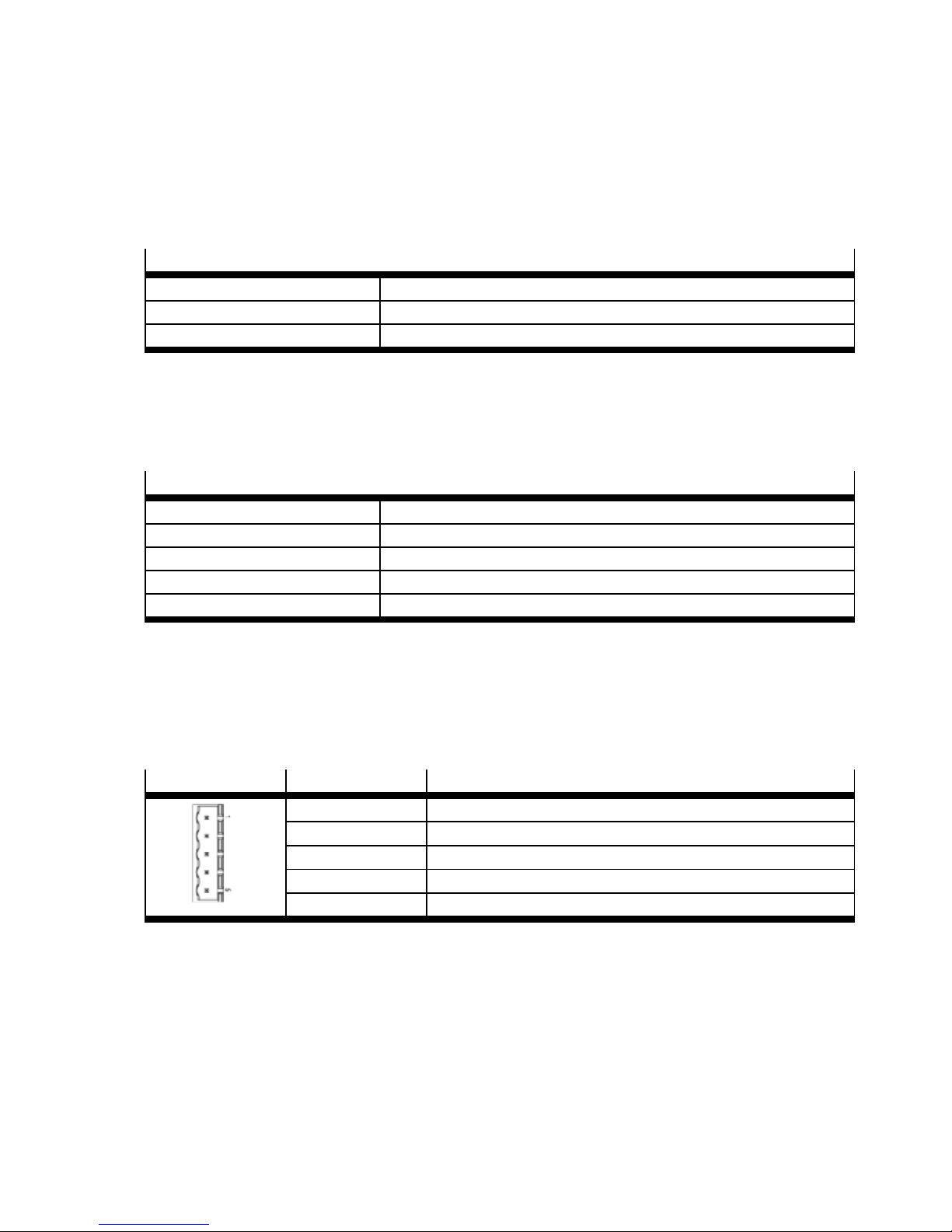
7 Pin allocation
DeviceNet allocation: 5 pin R5.08 plug
Pin Allocation
1 V2 CAN_L
3 SHIELD
4 CAN_H
5 V+
Tab. 7 Pin allocation
Festo – GDCP-CMGA-E1-DN-EN – 1201NH 15
Page 16

CMGA-E1-DN
Reproduction, distribution or sale of this document or communication of its c ontents to others without express authorization is
prohibited. Offenders will be liable for damages. All rights
reserved in the event that a patent, utility model or design patent
is registered.
16 Festo – GDCP-CMGA-E1-DN-EN – 1201NH
Copyright:
Festo AG & Co. KG
Postfach
D-73726 Esslingen
Phone:
+49 711 347 0
Fax:
+49 711 347 2144
e-mail:
[email protected]
Internet:
www.festo.com
Original: de
Version: 1201NH
 Loading...