

Page 1
Schwenkan tr ieb
DAPS..R..-F ..
Festo AG & Co. KG
Postfach
D-73726 Esslingen
++49/711/347-0
www.festo.com
Bedienungsanleitung 8001089
1110e
Original: de
Schwenkantrieb DAPS Deutsch.........................................
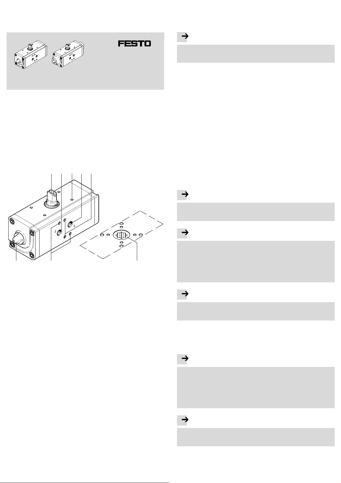
1 Bedienteile und Anschlüsse
Anschlüsse am Beispiel des doppeltwirkenden Schwenkantriebs DAPS:
2143 5
4 Transport und Lagerung
Sorgen Sie für Lagerbedingungenwie folgt: KurzeLagerzeiten undkühle, trockene,
schattige korrosionsgeschützte Lagerorte.
5 Voraussetzungen für den Produkteinsatz
Hinweis
Durch unsachgemäße Handhabung entstehenFehlfunktionen.
• Stellen Sie sicher, dass alle Anweisungendieses Kapitels stets eingehalten
werden. Dies macht das Produktverhalten ordnungsgemäß und sicher.
• Das Produkt ist kein Sicherheitsbauteil und darf nur gemäß der Zweckbestimmung eingesetzt werden.
• Verwenden Sie das Produkt im Originalzustand ohne jegliche eigenmächtige
Verände rung.
• Stellen Sie sicher, dass Sc hutzmaßnahmen nicht umgangen werden können.
• Sorgen Sie dafür, dass die Vorschriften für Ihren Einsatzort eingehalten werden,
z. B. vonBerufsgenossenschaft oder nationalen Institutionen.
• EntfernenSie die Verpackungen mit Ausnahme vorhandener Haftetikettenan
Druckluftanschlüssen (Verschmutzungsgefahr). Die Verpackungen sind vorgesehen für eine Verwertung auf stofflicher Basis (Ausnahme:Ölpapier = Restmüll).
• Vergleichen Sie die Grenzwerte in dieser Bedienungsanleitung mit Ihrem aktuellen Einsatzfall (z. B. Drücke, Kräfte, Momente, Massen, Geschwindigkeiten,
Temperaturen).Nur die Einhaltung der Belastungsgrenzenermöglicht es, das
Produkt gemäß der einschlägigen Sicherheitsrichtlinien zu betreiben.
• Berücksichtigen Sie die Umgebungsbedingungen am Einsatzort. Korrosive Umgebungen vermindern die Lebensdauer des Produkts.
• Schützen Sie das Gerät vor Druckschwankungen und Überschreitung der Betriebstemperatur. VerwendenSie Überdruc k- und Druckregelventile.
• Sorgen Sie für Druckluft mit ordnungsgemäßer Aufbereitung. Das Produkt benötigt getrockneteDruckluft, geölt oder ungeölt.
8 6
Fig. 1
1 Übertragungswellefür Endtaster-
anbau
2 Druckluftanschluss 2 (A) für Betä -
tigung und Linksdrehungdes
Schwenkantriebs
3 4 Befestigungsgewinde für End-
tasteranbau
4 Druckluftanschluss 4 (B) für Betä-
tigung und Rechtsdrehung des
Schwenkantriebs
Fig. 1
2Funktion
Der Schwenkantrieb DAPS ist vollständig auf die Anforderungen der Prozessindustrie zugeschnitten. Er wird für die Steuerung mediendurchströmter Prozessventile
in Anlagen verwendet.
Die Kolbenbewegung de s D APS wird über eine Joch-Kinematik (Scotch Yoke) in
eine Schwenkbewegung umgewandelt. Diese Kinematik ist nur innerhalbeines
Winkels von ca. 90° wirksam. Die einfachwirkende Ausführung mit Federrückstellung ist für verschiedene Versorgungsdrücke mit verschiedenen Federstärken ausgestattet.
Das angeschraubte Prozessventil nimmt das Reaktionsmoment des Schwenkantriebs auf. Dabei gelten die zulässigen Drehmomente gemäß den Technischen
Daten ( Katalogwww.festo.com/catalogue).
3 Anwendung
Bestimmungsgemäß dient der Schwenkantrieb DAPS zur Betätigung vonProzessventilen mit ca. 90° Drehwinkel (z. B.: Kugelhahn, Absperrklappe).
7
5 Befestigungsgewinde für Gewinde-
stift zur Ausrichtung des NAMURVentils
6 Ansicht von unten: sternförmige
Kupplung zur Aufnahme des Vierkant eines Prozessventils
7 Befestigungsgewinde für pneuma-
tisches NAMUR-Schaltventil
8 Kontermutter zur S icherung des
eingestelltenKolbenanschlags.
Hinweis
• Verwenden Sie unter normalen Bedingungen nur ungeölte Druckluft.
Der Schwenkantrieb DAPS besitzt eine Initialschmierung, die für die gesamte
Lebensdauer ausreicht.
Hinweis
Dauerbetrieb an der Grenze der angegebenen Umgebungstemperatur und Arbeitsfrequenz kann die Lebensdauer des Schwenkantriebs vermindern.
• Verwenden Sie beim Dauerbetrieb unter Extrembedingungengeölte Druckluft.
Das Öl musschemisch inert sein und darf nicht verkohlen.
Bei Verwendungvon geölter Druckluft:
Die Initialschmierung wird herausgeschwemmt. Der Schwenkantrieb darf nur
noch mit geölter Druckluft betriebenwerden.
Hinweis
Beim Einsatzdes SchwenkantriebsDAPS in explosionsfähiger Atmosphäre:
• Beachten Sie die Angaben und Hinweise in der beiliegenden Spezialdokumentation des Produkts.
• Externe Schlageinwirkungkann zu Fehlfunktionen führen. Schützen Sie das
Produkt vor herunterfallenden Gegenständen.
6 Einbau
Hinweis
Die folgendenAnweisungenzur Montage des Schwenkantriebs DAPS an ein
Prozessventil sind nur unter folgenden Voraussetzungen anzuwenden:
– Einbau des Schwenkantriebs inRohrleitungsrichtung.
– Bei Verwendung eines 2-Wege-Prozessventils:
Das 2-Wege-Prozessventil ist geschlossen.
– Bei Verwendung eines 3-Wege-Prozessventils:
Der Schaltzustanddes 3-Wege-Prozessventilsist bekannt.
Hinweis
Bei Verwendung eines 3-Wege-Prozessventils:
• Richten Sie den Schwenkantrieb so aus, dass die Anschlussöffnungen für ein
NAMUR-Ventil zur Seite ohne Rohrleitung zeigen.
Page 2
Hinweis
Ausströmendes Prozessmedium darf nicht in den Schwenkantrieb eindringen.
Das Gehäuse des Schwenkantriebs besitzt auf der Anschlussseite zum Prozessventileine Leckagenut.Sollte das Prozessventil undicht werden, so kanndie
Leckage über die offene Nut entweichen.
• Stellen S ie sicher, dass diese Leckagenut nicht abgedichtet wird. Auf diese
Weise wird sichergestellt, dass weder Prozessmedium noch ausströmende
Luft des Prozessventils in den Schwenkantrieb eindringt.
Die Montage des Schwenkantriebs DAPS erfolgt alternativ mit oder ohne Montagebrücke.
Bei hohen Mediumstemperaturen in Rohrleitung und Prozessventil:
• Verwenden Sie eine Montagebrücke und zusätzlich eine wärmeisolierte
Kupplungsverlängerung.
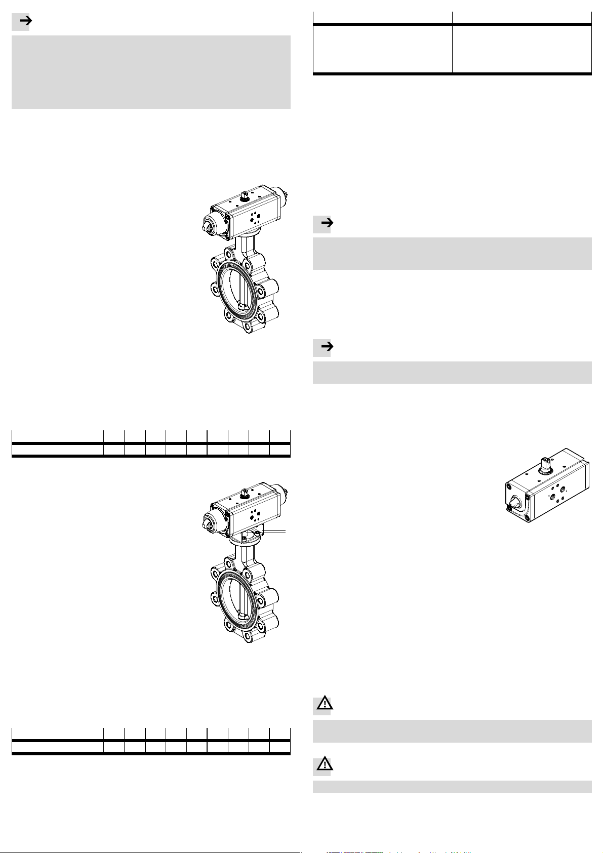
6.1 Einbau mechanisch
• Stellen Sie zur Montage des Schwenkantriebs
DAPS die Schaltwelle des Prozessventils so ein,
dass die verlangte Arbeitsweise zum Öffnen und
Schließen des Prozessventils realisiert wird.
• Beachten Sie, dass ein Prozessventil mit Absperrklappe nur in einer Richtung geöffnet und in Gegenrichtung geschlossen werden kann.
Zum Anbaudes Schwenkantriebs ohne Montagebrücke:
1. Setzen Sie den Schwenkantrieb auf die Schaltwelle des Prozessventils. Beachten Sie dabei, dass
der Vierkantdes Prozessventils ohne Verkantung
in der sternförmigen Kupplung des Schwenkantriebs sitzt.
Fig. 2
2. Befestigen Sie den Schwenkantrieb mit 4 korrosionsbeständigen Schrauben und Springringen
(Material: VA) am Anschlussflansch des Prozessventils.
3. Ziehen Sie alle Schrauben abwechselnd über Kreuz fest.
Anziehdrehmoment Fig. 3.
4. Fortsetzung Punkt 6.
DAPS
Anziehdrehmoment [Nm] 2,5 2,5 2,5 4 10 12 12 15 12
F03 F04 F05 F07 F10 F12 F14 F16 F25
Fig. 3
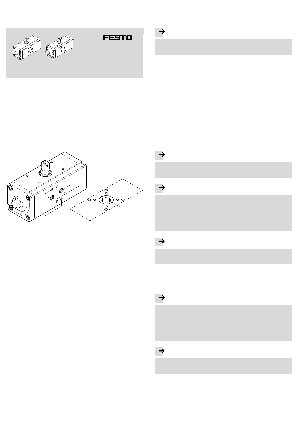
Zum Anbau des Schwenkantriebs mit Montagebrücke
benötigen Sie:
– eine Montagebrücke 9,
– eine Wellenverlängerung aJ.
1. Richten Sie die Montagebrücke so aus, dass deren
Stege in Richtung der Längsachse des Schwe nkan-
9
aJ
triebs ausgerichtet sind und gegebenenfallsdie
offene Seite der Montagebrücke zum Prozessventil
hin ausgerichtet ist.
2. Befestigen Sie die Montagebrücke am S c hwenkantrieb. Ziehen Sie die Schraubenjedoch noch nicht
fest.
3. Führen Sie die Wellenverlängerung durch die Montagebrücke in die sternförmige Kupplung an der
Unterseite des Schwenkantriebs ein. Beachten Sie
dabei, dass die Wellenverlängerungohne Verkantung in der Kupplung sitzt.
Fig. 4
4. Befestigen Sie den Schwenkantrieb mit Montagebrücke undWellenverlängerung am Anschlussflansch des Prozessventils. Beachten Sie dabei, dass der
Vierkant des Prozessventilsohne Verkantung in der Wellenverlängerung sitzt.
5. Ziehen Sie alle Schrauben abwechselnd über Kreuz fest.
Anziehdrehmoment Fig. 5.
DAPS
Anziehdrehmoment [Nm] 2,5 2,5 2,5 4 10 12 12 15 12
F03 F04 F05 F07 F10 F12 F14 F16 F25
Fig. 5
Nach Anbau des Schwenkantriebs:
6. Prüfen Sie, ob der Schwenkantrieb inder geforderten Drehrichtung arbeitet und
ob das Prozessventil die geforderte Stellung einnimmt.
7. Wenn der Schwenkantrieb nicht in der geforderten Drehrichtung arbeitet:
Führen S ie folgenden Umbau durch:
Doppeltwirkender Antrieb
1. Entfernen Sie das pneumatische Magnetventil.
2. Drehen Sie das Magnetventil um 180°.
3. Beachten Sie die Position des Gewindestifts
zur Orientierung einesNAMUR-Ventils.
4. Befestigen Sie das Magnetventil erneut.
Einfachwirkender Antrieb
1. Entfernen Sie die Schraubenauf der Antriebsseite.
2. Drehen Sie den Antriebum 90°,während er
noch über die Wellenverlängerung oder direkt mit dem Prozessventil verbunden ist.
3. Drehen Sie die Befestigungsschrauben fest.
6.2 Einbau pneumatisch Anschlüsse für die Luftzufuhr
• Schwenkantrieb DAPS, doppeltwirkend – Standardausführung
– Luftzufuhr am Anschluss 2 (A) – siehe Fig. 1 2
Drehbewegung der Schaltwelle gegen den Uhrzeigersinn.
– Luftzufuhr am Anschluss 4 (B) – siehe Fig. 1 4
Drehbewegung der Schaltwelle im Uhrzeigersinn.
• SchwenkantriebDAPS, einfachwirkendmit Federrückstellung – Standardausführung
– Luftzufuhr am Anschluss 4 (B): Drehbewegung gegen den Uhrzeigersinn.
– Federrückstellung: Drehbewegung im Uhrzeigersinn.
Hinweis
• Befestigen Sie ein Filterelementam Entlüftungsanschluss 2 ( A) des einfachwirkenden Schwenkantriebs DAPS.
Dadurch können keine Schmutzteilchen in das Produkt eindringen.
6.3 Einbau schaltungstechnisch
Zur Verwendungder pneumatischen Schaltventile:
• Beachten Sie bitte die Hinweise und Erläuterungen in der jeweiligen Bedienungsanleitung der Pneumatikventile.
7 Inbetriebnahme
Hinweis
• Stellen Sie sicher, dass die Betriebsbedingungen Kapitel 11 in den zulässigen Bereichenliegen.
Das Produkt ist nach Einbau und Anschluss grundsätzlich betriebsbereit.
• Stellen Sie sicher, dass die Umschaltung einesam Schwenkantrieb angebauten
Prozessventils ohne Behinderung erfolgenkann.
• Belüften Sie den Schwenkantrieb zunächst langsam.
Zur langsamen Einschaltbelüftungdient das Druckaufbauventil H EL.
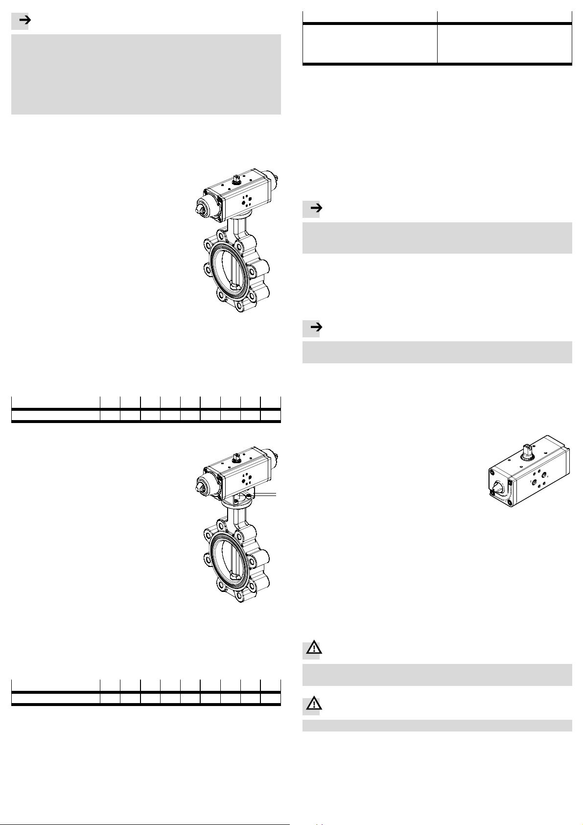
• Justieren Sie die Kolbenanschläge des Schwenkantriebs.
Diese Einstellung dient der Optimierung des Öffnungs-oder Schließverhaltensder angeschlossenen Prozessventile.
– Am doppeltwirkenden Schwenkantrieb kann nur
die Endlage bei Belüftung über Anschluss 2 (A)
justiert werden.
– Am einfachwirkendenSchwenkantrieb kann nur
Fig. 6
die Endlage durch Federrückstellung justiert
werden.
1. Lösen Sie die Kontermuttern auf beiden Seiten des DAPS.
Es erscheint auf jeder Seite eine Gewindestange zur Einstellung des Kolbenanschlags.
2. Drehen Sie mit einem Inbusschlüssel die Gewindestangen, bis das Prozessventil
korrekt schließt bzw. öffnet.
3. Drehen Sie die Kontermuttern wieder auf die Gewindestangen undziehen Sie
sie fest. Anziehdrehmoment: 5 Nm.
8WartungundPflege
Das Produkt ist bei bestimmungsgemäßem Einsatz entsprechend der Bedienungsanleitung wartungsfrei.
9Ausbau
War nung
Niemals einen unter Druck stehenden Schwenkantrieb ausbauen.
• Schalten Sie denpneumatischen Schaltkreisdrucklos.
War nung
• Schalten Sie vor dem Ausbau das Rohrleitungssystem drucklos.
1. Entfernen Sie gegebenenfalls den vorhandenenEndtasteranbau.
2. Entfernen Sie das pneumatische Schaltventil.
3. Lösen Sie die Schrauben am Flansch des Prozessventils.
Page 3

4. Nehmen Sie denSchwenkantrieb (gegebenenfalls inkl. Montagebrückeund
Kupplungsverlängerung) vom Prozessventil ab.
10 Störungsbeseitigung
• Setzen Sie sich bitte mit Festo in Verbindung.
11 TechnischeDaten
Baugröße
Einfachwirkender Antrieb Doppeltwirkender Antrieb
Schaltzeit pro Zyklus1)[s] Schaltzeit pro Zyklus1)[s]
DAPS-0008-... – 0,08
DAPS-0015-... 0,2 0,08
DAPS-0030-... 0,5 0,13
DAPS-0053-... 0,9 –
DAPS-0060-... – 0,2
DAPS-0090-... 1,3 –
DAPS-0106-... – 0,4
DAPS-0120-... 1,7 –
DAPS-0180-... 2,7 0,6
DAPS-0240-... 3,7 0,8
DAPS-0360-... 3,9 1,2
DAPS-0480-... 3,1 1,6
DAPS-0720-... 5,8 2,7
DAPS-0960-... 6,3 3,1
DAPS-1440-... 19,0 5,5
DAPS-1920-... 15,0 6,0
DAPS-2880-... 19,0 16,0
DAPS-3840-... – 12,0
DAPS-4000-... 25,0 –
DAPS-5760-... – 16,0
DAPS-8000-... – 22,0
1) Die Schaltzeiten sind in Sekunden angegeben und stellen Durchschnittswerte unter Leerlaufbedingun-
gen dar
Betriebsbedingungen DAPS
doppeltwirkend
Arbeitsdruck
Nennbetriebsdruck [bar] 5,6
Betriebsmedium Druckluft nach ISO8573-1:2010 [7:4:4]
Hinweis zum Betriebsmedium Geölter Betrieb möglich (im weiteren Betrieb
Umgebungstemperatur [°C] –20°C … +80
Schwenkwinkel [°] 90
VerstellbereichEndlage bei 0° [°] – – – ±5
VerstellbereichEndlage bei 90° [°] – ±2 ±2 ±5
Einbaulage beliebig
Druckluftschlauch Ø=8mm
Werkstoffe
Antriebswelle hochlegierter Stahl
Deckel Aluminium-Knetlegierung
Gehäuse Aluminium-Knetlegierung
1)
1)
Ausnahmenbei Geräten mit spezieller Kennzeichnung
Betriebsbedingungen DAPS
einfachwirkend
Arbeitsdruck
Nennbetriebsdruck [bar] 5,6
Betriebsmedium Druckluft nach ISO8573-1:2010 [7:4:4]
Hinweis zum Betriebsmedium Geölter Betrieb möglich (im weiteren Betrieb
Umgebungstemperatur [°C] –20°C … +80
Schwenkwinkel [°] 90
VerstellbereichEndlage bei 0° [°] – – – ±5
VerstellbereichEndlage bei 90° [°] ±2 ±2 ±2 ±5
Einbaulage beliebig
Druckluftschlauch Ø=8mm
Werkstoffe
Antriebswelle hochlegierter Stahl
Deckel Aluminium-Knetlegierung
Gehäuse Aluminium-Knetlegierung
1) Abhängig von der Federzahl bei einfachwirkenden Schwenkantrieben ergeben sichabweichende
1)
minimale Betriebsdrücke
DAPS0008
[bar] 2,8 ... 8,4 1 ... 7
erforderlich)
DAPS0015 ...
0180
[bar] 2,8 ... 8,4
erforderlich)
DAPS0015 ...
0360
DAPS0240 ...
0960
DAPS0480 ...
1920
DAPS1440 ...
1920
DAPS2880 ...
5760
DAPS2880,
4000
DAPS8000
Page 4
Quarter turn actuator
DAPS..R..-F ..
Festo AG & Co. KG
Postfach
D-73726 Esslingen
++49/711/347-0
www.festo.com
Operating instructions 8001089
1110e
Original: de
Quarter turn actuator DAPS English.....................................
1 Operating parts and connections
Example of c onnections on the double-acting quarter turn actuator DAPS:
2143 5
4 Transport and storage
Ensure storage conditions as follows: Short storage periods in cool, dry, shaded
and corrosion-protected locations.
5 Conditions of use
Note
Incorrect handling can result in malfunctioning.
• Make sure that all the instructions in this chapter are observed. The product
will then function correctly and reliably.
• The product is not a safety component and must only be used as designated.
• Use the product in its originalstate. Unauthorised modification is not permitted.
• Make sure that safety measures cannot be ignored.
• Ensure that all applicable national and local safety laws are adhered to.
• Remove the packing except for the adhesive labels on the supply ports
(to prevent dirt). The packing is intended for recycling (except for: oiled
paper = other waste).
• Compare the maximum values specified in these operating instructions with
your actual application (e.g. pressures, forces, torques, masses, speeds, temperatures). The product can only be used in accordance with the relevant safety
guidelines if the maximum load limits are observed.
• Take into consideration the ambient conditions at the location of use. Corrosive
environments reduce the service life of the product.
• Protect the device from fluctuations in pressure and excess operating temperature. Use control valves for regulating pressure and excess pressure.
• Ensure that there is a supply of correctly prepared compressed air. The product
requires dried compressed air, lubricated or unlubricated.
8 6
Fig. 1
1 Transmission shaft for mounting
the limit switch
2 Supply port 2 (A) for actuating and
anti-clockwise turningof the
quarter turn ac tuator
3 4 mounting threads for mounting
the limit switch
4 Supply port 4 (B) for act uating
and clockwise turning of the
quarter turn ac tuator
Fig. 1
2 Function
The DAPS quarter turnactuator is tailored c ompletely to the requirements of the
processing industry.It is used for controlling media-flow processing valves in systems.
The pistonmovement of the DAPS is converted to a rotary movement by means of
yoke kinematics(Scotch yoke).These kinematicsare onlyeffective within an angle
of approx. 90°. The single-acting design with spring return is equipped with different spring forces for use with different supply pressures.
The screwed-onprocessing valve records the moment of reaction of the quar ter
turn actuator. The torques permitted in acc ordance with the technical specifications ( catalogue www.festo.com/catalogue) applyhere.
3 Application
The quarter turn actuator DAPS has been designed for actuating processing valves
with approx. 90° rotation angle (e.g.: ball valve, butterfly valve).
7
5 Mountingthread for threaded
pin for aligning the NAMUR valve
6 View from below: star-shaped
coupling for holding the square
of a processing valve
7 Mountingthread for pneumatic
NAMUR switching valve
8 Lock nut for retaining the set
piston stop.
Note
• Use only non-lubricated compressed air under normal conditions.
The DAPS quarter turn actuator possesses an initial lubrication which suffices
for the complete service life.
Note
Continuous operation at the limits of the specifiedambient temperature and
work frequency can reduce the service life of the quarter turn actuator.
• Use lubricated compressed air for continuous operation under extreme conditions. The oil must be chemically inert and must not carbonise.
If lubricated compressed air is used:
The initial lubricationwill be washed out. The quarter turn actuator may then
only be operated with lubricated compressed air.
Note
If the DAPS quarter turn actuator is used in a potentially-explosive atmosphere:
• Please observe the notes and instructions in the accompanying special
documentationfor the device.
• Exposure to external impact can result in faults. Protect the device from objects
falling down onto it.
6 Fitting
Note
The following instructions on fitting the DAPS quarter turn actuator onto a processing
valve may only be used in the following circumstances:
– When the quarter turn actuator is fitted in the direction of the tubing
– If a 2-way processing valve is used:
The 2-way processing valve must be closed.
– If a 3-way processing valve is used:
The switching status of the 3-way processing valve must be known.
Note
If a 3-way processing valve is used:
• Align the quarter turn actuator so that the ports for a NAMUR valve face the
side without tubing.
Page 5
Note
Outflowing processing medium must not penetrate into the quarter turn actuator.
The housing of the quarter turn actuator possesses a leakage groove on the
connectionsidefortheprocessingvalve.Iftheprocessingvalveleaks,theleakage can flow through the open groove.
• Make sure that this leakage groove is not sealed. In this way you can be sure
that neither processing medium nor escaping air from the processing valve
can penetrate into the quarter turn actuator.
The DAPS quarter turnactuator can be fitted with or without a mountingadapter.
If there are high medium temperatures in the tubing and in the processing valve:
• Use a mounting adapter and also a heat-insulatedcoupling extension.
6.1 Fitting mechanical components
• In order to fit the DAPS quarter turn actuator, set
the switchingshaft of the processing valve so that
the desired working method for opening and
closing the processing valve is implemented.
• Note that a processing valve with butterfly valve
can only be opened in one direction and closed in
the opposite direction.
Fitting the quarter turn actuator without a mounting
adapter:
1. Place the quarter turn actuator on the switching
shaft of the processing valve. Make sure here that
the square of the processing valve sits in the starshaped coupling of the quarter turnactuator
without beingtilted.
Fig. 2
2. Fasten the quar ter turn actuator with 4 c orrosionresistant screws and springrings (material: VA)
to the connecting flange of the processing valve.
3. Tighten all the screws in diagonally opposite sequence.
Tightening torque Fig. 3.
4. Continued Point 6.
DAPS
Tightening torque [Nm] 2.5 2.5 2.5 4 10 12 12 15 12
F03 F04 F05 F07 F10 F12 F14 F16 F25
Fig. 3
To fit the quar ter turn actuator with a mounting
adapter you will need:
– a mounting adapter 9,
– a shaft extensionaJ.
1. Align the mounting adapter so that its steps face
the direction of the longitudinalaxis of the quarter
turn actuator and, if applicable, the open side of
the mounting bridge must face the processing
valve.
2. Fasten the mounting adapter on the quarter turn
actuator. Do not yet tighten the screws.
3. Pass the shaft extensionthrough the mounting
adapter into the star-shaped couplingon the
bottom of the quarter turnactuator. Make sure
that the shaft extension sits in the coupling
without beingtilted.
Fig. 4
4. Fasten the quarter turn actuator with mounting adapter and shaft extension to
the connecting flange of the processing valve. Make sure here that the square
of the processingvalve sits in the shaft extensionwithout beingtilted.
5. Tighten all the screws in diagonally opposite sequence.
Tightening torque Fig. 5.
DAPS
Tightening torque [Nm] 2.5 2.5 2.5 4 10 12 12 15 12
F03 F04 F05 F07 F10 F12 F14 F16 F25
Fig. 5
After fittingthe quarter turn actuator:
6. Check that the quarter turn actuator turns in the required direction of rotation
and whether the processing valve assumes the required position.
7. If the quarter turn actuator does not turn in the required direction of rotation:
Carry out the following conversion:
9
aJ
Double-actingdrives
1. Remove the pneumatic solenoid valve.
2. Turn the solenoid valve 180°.
3. Note the position of the th readed pin for
orientating a NAMUR valve.
4. Fasten the solenoid valve again.
Single-acting drives
1.Removethescrewsonthedriveside.
2. Turnthe drive 90° while it is still connected
via the shaft extension or directlywith the
processing valve.
3. Tighten the retaining screws.
6.2 Fitting pneumatic components Connections for the compressed air supply
• DAPS quarter turn actuator, double-acting– standard design
– Air supply at connection 2 (A) – see Fig. 1 2
Rotational movement of the shaft in an anti-clockwise direction.
– Air supply at connection 4 (B) – see Fig. 1 4
Rotational movement of the shaft in a clockwise direction.
• DAPS quarte r t urn actuator, single-acting with spring return – standard design
– Air supply at connection 4 (B): Rotational movement in an anti-clockwise
direction.
– Spring return: Clockwise rotation
Note
• Fasten a filter element to exhaust port 2 (A) of the single-acting quarter turn
actuator type DAPS.
In this way no dirt particles can enter the product.
6.3 Fitting electric components
Using the pneumatic switching valves
• Please note the instructions and explanations in the relevantoperating instructions for the pneumatic valves.
7 Commissioning
Note
• Make sure that the operating conditions chapter 11 lie within the permitted ranges.
The product is ready for operation as soon as it is fitted and electricallyand pneumatically connected.
• Make sure that a processing valve fitted to the quarter turn actuat or can be
switched without hindrance.
• Slowly pressurise the quarter turn actuator.
For slow start-up pressurisation use soft-start valve type HEL.
• Adjust the piston stops of the quarter turn actuator.
This setting serves for optimising the opening or
closing reaction of the connected processing val v es.
– On the double-acting quarter turn actuator only
the end position can be adjusted by pressurisation
via connection 2 (A).
– On the single-actin g quarter turn actuator only the
end position can be adjusted by spring return.
Fig. 6
1. Loosen the lock nuts on both sides of the DAPS.
On both sides there appears a threaded rod for setting the pistonstop.
2. Turnthe threaded rods with an Allen key until the processing valve opens or
closes correctly.
3. Screw the lock nuts onto the threaded rods againand tighten them. Tightening
torque: 5 Nm.
8 Care and maintenance
If used as designated in the operating instructions, the device will be free of maintenance.
9 Dismantling
War ning
Never try to dismantle a quarter turn actuator under pressure.
• Switch the pneumatic circuit pressureless.
War ning
• Switch the tubing system pressureless before dismantling.
1. If necessary, remove any existing limit switches.
2. Remove the pneumatic switching valve.
3. Loosen the screws on the flange of the processing valve.
4. Remove the quarter turn actuator (if necessary including mounting adapter and
coupling extension) from the processing valve.
Page 6

10 Eliminating faults
• Please contact Festo.
11 Technical specifications
Size
Single-acting drives Double-acting drives
Switching time per cycle1)[s] Switching time per cycle1)[s]
DAPS-0008-... – 0.08
DAPS-0015-... 0.2 0.08
DAPS-0030-... 0.5 0.13
DAPS-0053-... 0.9 –
DAPS-0060-... – 0.2
DAPS-0090-... 1.3 –
DAPS-0106-... – 0.4
DAPS-0120-... 1.7 –
DAPS-0180-... 2.7 0.6
DAPS-0240-... 3.7 0.8
DAPS-0360-... 3.9 1.2
DAPS-0480-... 3.1 1.6
DAPS-0720-... 5.8 2.7
DAPS-0960-... 6.3 3.1
DAPS-1440-... 19.0 5.5
DAPS-1920-... 15.0 6.0
DAPS-2880-... 19.0 16.0
DAPS-3840-... – 12.0
DAPS-4000-... 25.0 –
DAPS-5760-... – 16.0
DAPS-8000-... – 22.0
1) The switching times are sp ecified in seconds and represent average values under idling conditions
Operating conditions DAPS
double-acting
Work pressure
Rated operating pressure [bar] 5.6
Operating medium Compressed air to ISO 8573-1:2010 [7:4:4]
Note on the operating medium Lubricated o peration possible (required for continued
Ambient temperature [°C] –20°C … +80
ATEX ambient temperature [°C] –20°C ≤ T a ≤ +60
Swivel angle [°] 90
End-position adjusting
range at 0°
End-position adjusting
range at 90°
Mounting position as desired
Tubing dia. = 8 mm
Materials
Drive shaft high-alloy steel
Cover wrought aluminiumalloy
Housing wrought aluminiumalloy
1)
Exceptions for devices with special marking
1)
Operating conditions DAPS
single-acting
Work pressure
Rated operating pressure [bar] 5.6
Operating medium Compressed air to ISO 8573-1:2010 [7:4:4]
Note on the operating medium Lubricated o peration possible (required for continued
Ambient temperature [°C] –20°C … +80
ATEX ambient temperature [°C] –20°C ≤ T a ≤ +60
Swivel angle [°] 90
End-position adjusting
range at 0°
End-position adjusting
range at 90°
Mounting position as desired
Tubing dia. = 8 mm
Materials
Drive shaft high-alloy steel
Cover wrought aluminiumalloy
Housing wrought aluminiumalloy
1) Minimum operating pressures vary for single-acting quarter turn actuators depending upon spring
quantity
1)
DAPS0008
[bar] 2.8 ... 8.4 1 ... 7
operation)
[°] – – – ±5
[°] – ±2 ±2 ±5
DAPS0015 …
0180
[bar] 2.8 ... 8.4
operation)
[°] – – – ±5
[°] ±2 ±2 ±2 ±5
DAPS0015 …
0360
DAPS0240 …
0960
DAPS0480 …
1920
DAPS1440 …
1920
DAPS2880 …
5760
DAPS8000
DAPS2880,
4000
Page 7

Actuador giratorio
DAP S..R..-F..
Festo AG & Co. KG
Postfach
D-73726 Esslingen
++49/711/347-0
www.festo.com
Instrucciones de utilización 8001089
1110e
Original: de
Actuador giratorio DAPS..R..-F.. Español.................................
1 Elementos de mando y conexiones
Conexionesen el ejemplo del actuador giratorio de doble efecto DAPS:
2143 5
4 Transporte y almacenamiento
Garantice las siguientes condiciones de almacenamiento: breves períodos
de almacenamiento en lugaresfríos, secos, sombríos y protegidos contra la
corrosión.
5 Requisitos para la utilizacióndel producto
Indicación
Una manipulación inadecuada puede provocar un funcionamiento incorrecto.
• Deben observarse en todo momento todas las instrucciones dadas en este
capítulo. Con ello, el producto funcionará de forma correcta y fiable.
• El producto no es ningún componente de seguridad y sólo debe utilizarse para
el uso previsto.
• Utilice el producto en su estado original sin efectuar modificaciones de ningún
tipo.
• Asegúrese de que no puedan eludirse las medidas de seguridad.
• Asegúrese de que se cumplen todas las normas vigentes de seguridad locales y
nacionales.
• Retire los embalajes, excepto las etiquetas adhesivas situadasen la alimentación de presión (peligro de contaminación). El embalaje está previsto para ser
reciclado (excepción: papel aceitado = desechos residuales).
• Compare los valores límite especificados en estas instrucciones de funcionamiento c on su aplicación actual (p. ej. presiones, fuerzas, pares, masas,
velocidades, temperaturas). El producto sólo puede hacerse funcionar si se
observan los límites de carga de acuerdo con las directricesde seguridad
correspondientes.
• Tenga en cuenta las condiciones ambientales del lugar de utilización. Los
entornos corrosivos reducen la vida útil del producto.
• Proteja el producto frente a posibles oscilaciones de presión y excesos de la
temperatura de servicio. Utilice reguladores de presión y válvulas de
sobrecarga.
• Asegúrese de que el aire comprimido se halla convenientemente preparado.
El producto requiere aire comprimido seco, con o sin lubricación.
8 6
Fig. 1
1 Eje de transmisión para accesorio
final de carrera
2 Alimentaciónde presión 2 (A) para
accionamientoy rotacióna la
izquierda del actuador giratorio
3 4 Rosca de fijaciónpara accesorio
final de carrera
4 Alimentación de presión 4 (B)
para accionamientoy rotación
a la derecha del actuador giratorio
Fig. 1
2 Funcionamiento
El actuador giratorio DAPS está adaptado por completo a las exigencias de la
industria de procesos. Se utiliza para el control de válvulas de proceso por las que
fluye el medio en instalaciones.
El movimiento del émbolo del DAPS se transforma mediante un yugo escocés
(scotch-yoke) en un movimiento giratorio. Esta cinemática sólo es efectiva dentro
de un ángulo de unos 90°. La versión de simple efecto con reposición por muelle
está equipada con muelles de distinta fuerza para distintas presiones de
alimentación.
La válvula de proceso atornillada absorbe el momento de respuesta del actuador
giratorio.Son válidos los pares permitidos según las especificacionestécnicas
( el catálogo en www.festo.com/catalogue).
3 Aplicaciones
El actuador giratorio DAPS ha sido diseñado para el ac c ionamiento de válvulas de
proceso con un ángulo de giro de unos 90° (p. ej.: válvulas de bola y de mariposa).
7
5 Rosca de fijación para pasador
roscado para alineación de la
válvula NAMUR
6 Vista desde abajo: acoplamiento
en forma de estrella para el
alojamientodel cuadrado macho
de una válvula de proceso
7 Rosca de fijación para válvula de
conexión neumática NAMUR
8 Contratuerca para asegurar el tope
de émbolo ajustado
Indicación
• En condiciones normales utilice únicamente aire comprimido sin lubricar.
El actuador giratorio DAPS dispone de una lubricación inicial suficiente para
toda la vida útil.
Indicación
El servicio permanente al límitede la temperatura ambiente y de la frecuencia de
trabajo indicadas puede mermar la vida útil del actuador giratorio.
• En servicio permanente y condiciones extremas utilice aire comprimido lubricado. El aceite lubricante debe ser químicamente inerte y no debe carbonizarse.
Si se utiliza aire comprimido lubricado:
La lubricación inicial se elimina. Después el actuador giratorio sólo puede utilizarse con aire comprimido lubricado.
Indicación
Si se utiliza el actuador giratorio DAPS en atmósfera con riesgo de explosión:
• Consulte las especificaciones e instrucciones en la documentaciónespecial
del producto.
• La exposición a impactos externos puede provocar un funcionamiento
incorrecto. Evite la caída de objetos encima del producto.
6Instalación
Indicación
Las siguientes instrucciones de montaje del actuador giratorio DAPS en una
válvula de proceso sólo deben aplicarse bajo las siguientes condiciones:
– Montaje del actuador giratorio en el sentido de la tubería.
– Si se utiliza una válvula de proceso de dos vías: La válvula de proceso de dos
vías está cerrada.
– Si se utiliza una válvula de proceso de tres vías: Se conoce el estado de con-
mutación de la válvula de proceso de tres vías.
Indicación
Si se utiliza una válvula de proceso de tres vías:
• Alinee el actuador giratorio de manera que los taladros para una válvula
NAMUR miren hacia el lado en el que no hay tubería.
Page 8

Indicación
El fluido que sale no debe penetrar en el actuador giratorio.
El cuerpo del actuador giratorio posee una ranura de escape en el lado de conexión de la válvula de proceso. Si la válvula de proceso pierde estanqueidad,
pueden producirse fugas por la ranura abierta.
• Asegúrese de que no se obture la ranura de escape. De esta manera se garantizaquenopenetrefluidodeprocesooairedeescapedelaválvuladeproceso en el actuador giratorio.
El actuador giratorio DAPS se puede montar con o sin adaptador de montaje.
Si la temperaturadel fluido es elevada en la tubería y en la válvula de proceso:
• Utilice un adaptador de montaje y adicionalmente una prolongación de
acoplamiento con aislamiento térmico.
6.1 Instalación mecánica
• Para el montaje del actuador giratorio DAPS
coloqueelejedemaniobradelaválvulade
proceso de maneraque sea posible abrir y cerrar
la válvula correctamente.
• Asegúrese de que una válvula de proceso de
mariposa sólo pueda abrirse en un sentido y
cerrarse en el sentido opuesto.
Para la instalación del actuador giratorio sin
adaptador de montaje:
1. Coloque el ac tuador giratorio sobre el eje de
maniobra de la válvula de proceso. Asegúrese de
que el cuadrado macho de la válvula de proceso
está alojado en el acoplamiento en forma de
estrella del actuador giratorio sinladearse.
Fig. 2
2. Fije el actuador giratorio con 4 tornillos y anillos
resistentes a la oxidación (material: VA) en la brida
de conexión de la válvula de proceso.
3. Apriete todos los tornillos en secuencia diagonal alternativa.
Par de apriete Fig. 3.
4. Continuación punto 6.
DAPS
Par de apriete [Nm] 2,5 2,5 2,5 4 10 12 12 15 12
F03 F04 F05 F07 F10 F12 F14 F16 F25
Fig. 3
Para la instalación del actuador giratorio con
adaptador de montaje se necesita:
– un adaptador de montaje 9 y
– una piezade prolongación del eje aJ.
1. Alinee el adaptador de montaje de manera que sus
nervios estén orientados en el sentido del eje
9
aJ
longitudinal del actuador giratorio y, dado el caso,
el lado abierto del adaptador de montaje esté
orientado hacia la válvula de proceso.
2. Fije el adaptador de montaje al actuador giratorio.
Pero no apriete aún los tornillos.
3. Introduzca la pieza de prolongacióndel eje a
través del adaptador de montaje en el acoplamiento en forma de estrella en la parte inferior
del actuador giratorio. Asegúrese de que la pieza
de prolongacióndel eje esté alojada en el
acoplamiento sin ladearse.
Fig. 4
4. Fije el actuador giratorio con adaptador de montaje y la pieza de prolongación
del eje en la brida de conexiónde la válvula de proceso. Asegúrese de que el
cuadrado macho de la válvula de proceso está alojado en la pieza de
prolongación del eje sin ladearse.
5. Apriete todos los tornillos en secuencia diagonal alternativa.
Par de apriete Fig. 5.
DAPS
Par de apriete [Nm] 2,5 2,5 2,5 4 10 12 12 15 12
F03 F04 F05 F07 F10 F12 F14 F16 F25
Fig. 5
Después del montaje del actuador giratorio:
6. Compruebe que el actuador girat orio funciona en el sentido de giro requerido y
que la válvula de proceso adopta la posición correcta.
7. Si el actuador girato rio no funciona en el sentido de giro requerido:
Realice el siguiente cambio en el montaje:
Actuador de doble efecto
1. Retire la electroválvula neumática.
2. Gire la electroválvula 180°.
3. Observe la po sición del pasador roscado
para la orientación de una válvula NAMUR.
4. Vuelva a fijar la electroválvula.
Actuador de simple efecto
1. Extraiga los tornillos del lado del actuador.
2. Gire el actuador 90°, mientras aún está conectado a la válvula de proceso directamente
o mediante la pieza de prolongación del eje.
3. Apriete lo s tornillos de fijación.
6.2 Instalación neumática Conexiones para la alimentación de aire
• Actuador giratorio DAPS de doble efecto, modelo estándar
– Alimentación de aire en la conexión 2 (A) – véase Fig. 1 2
Movim iento de giro del eje de maniobra en sentido contrario a las agujas del reloj.
– Alimentación de aire en la conexión 4 (B) – véase Fig. 1 4
Movimiento de giro del eje de maniobra en el sentido de las agujas del reloj.
• Actuador giratorio DAPS de simple efecto con reposición por muelle, modelo
estándar
– Alimentación de aire en la conexión 4 (B): Movimiento de giro en sentido
contrario a las agujas del reloj.
– Reposición por muelle: Movimiento de giro en el sentido de las agujas del
reloj.
Indicación
• Fije un elemento filtrante en la toma de escape 2 (A) del actuador giratorio de
simple efecto DAPS.
Impedirá que penetren partículas de suciedad en el producto.
6.3 Instalación del circuito eléctrico
Para la utilización de las válvulas de conexión neumáticas:
• Tenga en cuenta las indicaciones y explicaciones en las instrucciones de
utilización de las válvulas neumáticas correspondientes.
7 Puesta en funcionamiento
Indicación
• Asegúrese de que las condiciones de funcionamiento capítulo 11 están
dentro de los márgenes permitidos.
En principio el pro ducto está listo para el funcionamiento después del montaje y la
conexión.
• Asegúrese de que la conmutación de una válvula de proceso instalada en el
actuador giratorio se puede realizar sin obstáculos.
• Primero aplique presión al actuador giratorio lentamente.
Para un aumento lento y progresivo de la presión use una válvula de arranque
progresivo tipo HEL.
• Ajuste los topes de émbolo del actuador giratorio.
Este ajuste sirve para optimizar el comportamiento de apertura y cierre de las válvulas de
proceso conectada s.
– En el actuador giratorio de doble efecto sólo
puede ajustarse la posición final cuando se
aplica presiónmediante la conexión 2 (A).
– En el actuador giratorio de efecto simple sólo
puede ajustarse la posición final mediante
Fig. 6
reposición por muelle.
1. Afloje las contratuercasen ambos lados del DAPS.
En cada lado aparece una barra roscada para el ajuste del tope de émbolo.
2. Gire las barras roscadas con una llave allen hasta que la válvula de proceso
se cierre y abra correctamente.
3. Vuelva a girar las contratuercas en las barras roscadas y apriételas. Par de
apriete: 5 Nm.
8 Cuidados y mantenimiento
Si se utiliza como se indica en las instrucciones, el producto está libre de
mantenimiento.
9Desmontaje
Advertencia
No desmonte nunca un actuador giratorio mientras se encuentre bajo presión.
• Ponga el circuito neumático en un estado sin presión.
Advertencia
• Antes del desmontaje ponga el sistema de tuberías en un estado sin presión.
1. Dado el caso, extraiga el accesorio final de carrera.
2. Retire la válvula de conexión neumática.
3. Afloje los tornillos en la brida de la válvula de proceso.
4. Retire el actuador giratorio (dado el caso, incluidos el adaptador de montaje y la
prolongación del acoplamiento) de la válvula de proceso.
Page 9

10 E liminación de fallos
• Póngase en contacto con Festo.
11 Especificaciones técnicas
Tama ño
DAPS-0008-... – 0,08
DAPS-0015-... 0,2 0,08
DAPS-0030-... 0,5 0,13
DAPS-0053-... 0,9 –
DAPS-0060-... – 0,2
DAPS-0090-... 1,3 –
DAPS-0106-... – 0,4
DAPS-0120-... 1,7 –
DAPS-0180-... 2,7 0,6
DAPS-0240-... 3,7 0,8
DAPS-0360-... 3,9 1,2
DAPS-0480-... 3,1 1,6
DAPS-0720-... 5,8 2,7
DAPS-0960-... 6,3 3,1
DAPS-1440-... 19,0 5,5
DAPS-1920-... 15,0 6,0
DAPS-2880-... 19,0 16,0
DAPS-3840-... – 12,0
DAPS-4000-... 25,0 –
DAPS-5760-... – 16,0
DAPS-8000-... – 22,0
1) Los tiempos de conmutación están indicados en segundos y representan valores promedio en
condiciones de marcha sin carga
Actuador de simple efecto Actuador de doble efecto
Tiempo de conmutación
por ciclo
1)
[s]
Tiempo de conmutación
por ciclo
1)
[s]
Condiciones de funcionamiento
de DAPS de doble efecto
Presión de trabajo
Presión de servicio nominal [bar] 5,6
Medio de funcionamiento Aire comprimido según ISO 8573-1:2010 [7:4:4]
Nota sobre medio de
funcionamiento
Temperatura ambiente [°C] –20°C … +80
Temperatura ambiente ATEX [°C] –20 °C ≤ Ta ≤ +60
Ángulo de giro [°] 90
Margen de ajuste de final de
carrera con 0°
Margen de ajuste de final de
carrera con 90°
Posición de montaje Indiferente
Tubosflexibles Ø=8mm
Materiales
Ejedeaccionamiento Acero de aleación fina
Tap a Aleación de aluminio
Cuerpo Aleación de aluminio
1)
Excepciones en aparatos con identificación especial
1)
Condiciones de funcionamiento
de DAPS de simple efecto
Presión de trabajo
Presión de servicio nominal [bar] 5,6
Medio de funcionamiento Aire comprimido según ISO 8573-1:2010 [7:4:4]
Nota sobre medio de
funcionamiento
Temperatura ambiente [°C] –20°C … +80
Temperatura ambiente ATEX [°C] –20 °C ≤ Ta ≤ +60
Ángulo de giro [°] 90
Margen de ajuste de final de
carrera con 0°
Margen de ajuste de final de
carrera con 90°
Posición de montaje Indiferente
Tubosflexibles Ø=8mm
Materiales
Ejedeaccionamiento Acero de aleación fina
Tap a Aleación de aluminio
Cuerpo Aleación de aluminio
1) Las presiones de funcionamiento mínimas varían ligeramente en función de la cantidad de muelles de
los actuadores giratorios de simple efecto
1)
DAPS0008
[bar] 2,8 ... 8,4 1 ... 7
Funcionamiento con lubricación posible (requerido en
otros funcionamientos)
[°] – – – ±5
[°] – ±2 ±2 ±5
DAPS0015 …
0180
[bar] 2,8 ... 8,4
Funcionamiento con lubricación posible (requerido en
otros funcionamientos)
[°] – – – ±5
[°] ±2 ±2 ±2 ±5
DAPS0015 …
0360
DAPS0240 …
0960
DAPS0480 …
1920
DAPS1440 …
1920
DAPS2880 …
5760
DAPS8000
DAPS2880,
4000
Page 10

Vérin oscillant
DAP S..R..-F..
Festo AG & Co. KG
Postfach
D-73726 Esslingen
++49/711/347-0
www.festo.com
Notice d’utilisation 8001089
1110e
Original : de
Vérin oscillant DAPS..R..-F.. Français....................................
1 Eléments de commande et raccordements
Raccordements conformément au vérin oscillant à double effet DAPS :
2143 5
4 Transport et stockage
Respecter les c onditions de stockage suivantes : des temps de stockage courts et
des emplacementsde stockage frais, secs, ombragés et protégés de la c orrosion.
5 Conditions d’utilisation du produit
Nota
Une utilisation incorrecte peut causer des dysfonctionnements.
• Veiller au respect permanent de toutes les consignes énoncées dans ce chapitre. Le respect des instructionsgarantit un fonctionnement correct et en toute
sécurité du produit.
• Le produit n’est pas un composant de sécurité et doit uniquement être utilisé
conformément à l’usage prévu.
• Utiliser le produit dans son état d’origine, sans apporter de modifications.
• Vérifier que les mesures de sécurité ne peuvent pas être contournées.
• S’assurer du respect des prescriptions en vigueur sur le lieu d’utilisation émanant notamment des organismes professionnels et des réglementations nationales.
• Enleverles emballages, à l’exception des étiquettes adhésives collées sur les
raccords d’alimentation (risque de pollution). Les emballages sont conçus de
sorte que leurs matériaux puissent être recyclés (exception : papier huileux =
déchet résiduel).
• Comparer les valeurs limites indiquées dans cette notice d’utilisation au cas réel
(par ex. pressions, forces, couples, masses, vitesses, températures). Seul le
respect des limites de charge permet un fonctionnement du produit conforme
aux directivesde sécurité en vigueur.
• Tenir compte des conditions ambiantes sur le lieu d’utilisation. Les environnements corrosifs diminuent la durée de vie du produit.
• Protéger l’appareil contre les fluctuations de pression et le dépassement de la
température de service. Utiliser les soupapes de décharge et les manodétendeurs.
• Veillez au traitement correct de l’air comprimé. Le produit nécessite de l’air
comprimé sec, lubrifié ou non lubrifié.
8 6
Fig. 1
1 Arbre de transmission pour kit de
fixation de capteur
2 Raccord d’alimentation 2 (A) pour
lacommandeetlarotationversla
gauche du vérin oscillant
3 4 taraudages de fixation pour le kit
de fixation de capteur
4 Raccord d’alimentation 4 (B) pour
lacommandeetlarotationversla
droite du vérin oscillant
Fig. 1
2Fonction
Le vérin oscillant DAPS est entièrement conçu pour répondre aux exigences de
l’industrie du process. Il est utilisé pour commander des vannes de process traversées par des fluides dans les installations.
Le mouvement des pistons du DAPS est transformé en un mouvement oscillant
grâce à la cinétique de joug (Scotch Yoke). Cette cinétique n’est efficace que dans
un angle d’environ 90°. La version à simple effet avec rappel par ressort est équipée de ressorts de différentes résista nces pour les différentes pressions d’alimentation.
La vanne de process vissée enregistre le couple antagoniste du vérin oscillant. Les
couples de serrage admissibles s’appliquent conformément aux caractéristiques
techniques ( voir catalogue www.festo.com/catalogue).
3 Application
Conformément à l’usage prévu, le vérin oscillant DAPS est utilisé pour la commandedevannesdeprocessd’unanglederotationd’environ90°(parex.:robinet
à boisseau sphérique, robinet à papillon).
7
5 Taraudage de fixation pour tige
filetée pour l’alignement du
distributeur NAMUR
6 Vue de dessous : coupleur en
étoile pour loger le carré d’une
vanne de proc ess
7 Taraudage de fixation pour
distributeur NAMUR pneumatique
8 Contre-écrou pour sécuriser la
butée de piston définie.
Nota
• Toujours utiliser de l’air comprimé non lubrifié dans des conditions normales.
Le vérin oscillant DAPS possède une lubrification d’origine qui suffit pour la
durée de vietotale.
Nota
Un fonctionnement continu aux limites de la température ambiante et de la
cadence indiquées peut réduire la durée de vie du vérin oscillant.
• Utiliser de l’air comprimé lubrifié lors d’un fonctionnement continu dans des
conditions extrêmes. L’huile doit être chimiquement inerte et ne doit pas
carboniser.
Lors de l’utilisation d’air comprimé lubrifié :
La lubrification d’origine est évacuée. Le vérin oscillant ne peut plus fonctionner
qu’avec de l’air comprimé lubrifié.
Nota
Lors de l’utilisation du vérin oscillant DAPS dans une atmosphère explosible :
• Respecter les indications et conseils fournis dans la notice d’utilisation du
produit.
• Des chocs exte r nes peuvent provoquer des dysfonctionnements. Protéger le
produit contre toute chute d’objets.
6Montage
Nota
Les consignes suivantes pour le montage du vérin oscillant DAPS sur une vanne
de process ne sont applicables que dans les conditions suivantes :
– Montage du vérin oscillant dans le sens de la tuyauterie.
– Lors de l’utilisation d’une vanne de process à 2 voies : La vanne de process
à 2 voies est fermée.
– Lors de l’utilisation d’une vanne de process à 3 voies : L’état de commutation
de la vanne de process à 3 voies est connu.
Nota
Lors de l’utilisation d’une vanne de process à 3 voies :
• Orienter le vérin oscillant de façon à ce que les entrées de raccordement pour
un distributeur NAMUR pointent vers le côté sans tuyauterie.
Page 11

Nota
Le fluide de processus qui s’écoule ne doit pas pénétrer dans le vérin oscillant.
Le boîtier du vérin oscillant possède une rainure pour les fuites côté raccordement de la vannede process. Si la vannede process n’est plus étanche, la fuite
peut s’écouler par la rainure ouverte.
• S’assurer que cette rainure pour les fuites n’est pas étanche. On garantit ainsi
que ni le fluide de processus ni l’air émis par la vanne de process n’infiltrent le
vérin oscillant.
Le montage du vérin oscillant DAPS s’effectue avec ou sans adaptateur de montage.
Encasdefortestempératuresdefluidedanslatuyauterieetlavannedeprocess:
• Utiliser un adaptateur de montage ainsi qu’une extension d’accouplement à
isolation thermique.
6.1 Montage mécanique
• Pour le montage du vérin oscillant DAPS, régler
l’arbre de commutation de la vanne de process, de
façon à ce que la procédure longue d’ouverture et
de fermeture de la vanne de process soit mise en
œuvre.
• Noter qu’une vanne de process avec clapet d’arrêt
ne peut être ouverte que dans un sens et fermée
dans l’autre.
Pour le montage du vérin oscillant sans adaptateur
de montage :
1. Placer le vérin oscillant sur l’arbre de commutation
de la vanne de process. Veiller à ce que le carré de
la vanne de process soit positionné sans
inclinaison du coupleur en étoile du vérin oscillant.
Fig. 2
2. Fixer le vérin oscillant avec 4 vis anti-corrosion et
des anneaux à ressort (matériel : VA) sur la bride
de raccordement de la vanne de process.
3. Serrer toutes les vis en croix en alternant.
Coupledeserrage Fig. 3.
4. Suite point 6.
DAPS
Couple de serrage [Nm] 2,5 2,5 2,5 4 10 12 12 15 12
F03 F04 F05 F07 F10 F12 F14 F16 F25
Fig. 3
Matériel nécessaire pour le montage du vérin
oscillant avec adaptateur de montage :
– un adaptateur de montage 9,
– une extension d’arbre aJ.
1. Orienter l’adaptateurde montage de façon à ce
que les brides soient dirigées dans le sens de l’axe
9
aJ
longitudinal du vérin oscillant et, le cas échéant, à
ce que le côté ouvert de l’adaptateur de montage
soit aligné avec la vanne de process.
2. Fixer l’adaptateur de montage sur le vérin
oscillant. Serrer les vis mais pas complètement.
3. Introduire l’extension d’arbre dansl’adaptateur
de montage dans le coupleur en étoile sur la face
inférieure du vérin oscillant. Veiller à ce que
l’extension soit logée sans inclinaison soit dans
le coupleur.
Fig. 4
4. Fixer le vérin oscillant avec l’adaptateur de montage et l’extension d’arbre sur
la bride de raccordement de la vanne de process. Veiller à ce que le carré de la
vanne de process soit logé sans inclinaisondans l’extensiond’arbre.
5. Serrer toutes les vis en croix en alternant.
Coupledeserrage Fig. 5.
DAPS
Couple de serrage [Nm] 2,5 2,5 2,5 4 10 12 12 15 12
F03 F04 F05 F07 F10 F12 F14 F16 F25
Fig. 5
Après le montage du vérin oscillant :
6. Vérifier si le vérin oscillant fonctionne dans le sens de rotation requis et si la
vanne de process se positionne dans la position requise.
7. Si le vérin oscillant ne fonctionne pas dans le sens de rotation requis :
Procédez au test fonctionnel suivant :
Entraînement à double effet
1. Retirer l’électro-distributeur pneumatique.
2. Tourner l’électro-distributeur de 180°.
3.Respecterlapositiondelatigefiletéepour
l’orientation d’un distributeur NAMUR.
4. Renouveler la fixation de
l’électro-distributeur.
Entraînement à simple effet
1. Retirer les vis du côté entraînement.
2. Tournerl’entraînement de 90° pendant qu’il
est encore raccordé à l’extension d’arbre ou
directement à la vannede process.
3. Serrer les vis de fixation.
6.2 Montagepneumatique Raccordspourl’alimentationenair
• Vérin oscillant DAPS, double effet – version standard
– Alimentation en air sur le raccord 2 (A) – voir Fig. 1 2
Mouvementde rotation de l’arbre de commutation dans le sens antihoraire.
– Alimentation en air sur le raccord 4 (A) – voir Fig. 1 4
Mouvement de rotation de l’arbre de commutation dans le sens horaire.
• Vérin oscillant DAPS, simple effet avec rappel par ressort – version standard
– Alimentation en air au raccord 4 (B) : Mouvement de rotationdans le sens
antihoraire.
– Rappel par ressort : Sens de rotation dans le sens horaire.
Nota
• Fixer un filtre sur l’orifice de purge 2 (A) du vérin oscillant DAPS à simple effet.
De cette façon, aucune particule d’impureté ne peut s’infiltrer dans le produit.
6.3 Principederaccordement
Pour l’utilisation des distributeurs pneumatiques :
• Respecter les conseils et les explications fournis dans la notice d’utilisation
correspondante des distributeurs pneumatiques.
7 Mise en service
Nota
• Assurez-vous que l’appareil fonctionne dans les plages admissibles
Chapitre 11.
Après le montage et le raccordement, le produit est en principe prêt à fonctionner.
• S’assurer que la commutation d’une vanne de process montée sur un vérin
oscillant peut s’effectuer sans aucune gêne.
• Mettre lentement le vérin oscillant sous pression.
Le distributeur de mise en pression progressive de type HEL est utilisé pour une
mise sous pression progressive.
• Ajuster les butées de pistons du vérin oscillant.
Ce réglage permet d’optimiser le compor tement
d’ouverture ou de fermet ure de la vanne de
process raccordée.
– Sur le vérin oscillant à double effet, seule la
position finale peut être ajustée par une mise
sous pression via le raccord 2 (A).
– Sur le vérin oscillant à simple effet, la position
finale peut uniquement être ajustée au moyen
Fig. 6
du rappel par ressort.
1. Desserrer les contre-é crous sur les deux côtés du DAPS.
Sur chaque côté apparaît une tige filetée pour l’ajustage de la butée des
pistons.
2. Tourner les tiges filetées avec une clé Allen jusqu’à ce que la vanne de process
se ferme ou s’ouvre correctement.
3. Remonter les c ontre-écrous à nouveau sur les tiges filetées et serrer
fermement. Couple de serrage : 5 Nm.
8 Maintenance et entretien
Utilisé conformément à l’usage prévu selon la notice d’utilisation, le produit ne
nécessite aucunentretien.
9Démontage
Avertissement
Ne jamais démonter un vérin oscillant sous pression.
• Couper la pression dans le circuit pneumatique.
Avertissement
• Couper la pression dans le système de tuyauterie avant le démontage.
1. Retirer le cas échéant le kit de fixation de capteur.
2. Retirer le distributeur pneumatique.
3. Desserrer les vis sur la bride de la vanne de process.
4. Retirer le vérin oscillant (le cas échéant avec adaptateur de montage et l’extension du coupleur) de la vanne de process.
Page 12

10 Dé pannage
• Contactez Festo.
11 Caractéristiques techniques
Taille
DAPS-0008-... – 0,08
DAPS-0015-... 0,2 0,08
DAPS-0030-... 0,5 0,13
DAPS-0053-... 0,9 –
DAPS-0060-... – 0,2
DAPS-0090-... 1,3 –
DAPS-0106-... – 0,4
DAPS-0120-... 1,7 –
DAPS-0180-... 2,7 0,6
DAPS-0240-... 3,7 0,8
DAPS-0360-... 3,9 1,2
DAPS-0480-... 3,1 1,6
DAPS-0720-... 5,8 2,7
DAPS-0960-... 6,3 3,1
DAPS-1440-... 19,0 5,5
DAPS-1920-... 15,0 6,0
DAPS-2880-... 19,0 16,0
DAPS-3840-... – 12,0
DAPS-4000-... 25,0 –
DAPS-5760-... – 16,0
DAPS-8000-... – 22,0
1) Les temps de commutation sont indiqués en secondes et représentent des valeursmoyennes dans des
conditions de marche à vide
Entraînement à simple effet Entraînement à double effet
Temps de commutation par
1)
cycle
[s]
Temps de commutation par
1)
cycle
[s]
Conditions de service du DAPS à
double effet
Pression de travail
Pression de service nominale [bar] 5,6
Fluide autorisé Air comprimé selon ISO 8573-1:2010 [7:4:4]
Remarque concernant le fluide
autorisé
Température ambiante [°C] -20 °C … +80
Température ambiante ATEX [°C] –20 °C ≤ Ta ≤ +60
Angle d’oscillation [°] 90
Plagederéglagedelafinde
course pour 0°
Plagederéglagedelafinde
course pour 90°
Position de montage Indifférente
Tuyaupneumatique Ø=8mm
Matériaux
Arbre d’entraînement Acier fortement allié
Couvercle Alliage d’aluminium
Carter Alliage d’aluminium
1)
Exceptions pour les appareils avec marquage particulier
1)
Conditions de service du DAPS à
simple effet
Pression de travail
Pression de service nominale [bar] 5,6
Fluide autorisé Air comprimé selon ISO 8573-1:2010 [7:4:4]
Remarque concernant le fluide
autorisé
Température ambiante [°C] -20 °C … +80
Température ambiante ATEX [°C] –20 °C ≤ Ta ≤ +60
Angle d’oscillation [°] 90
Plagederéglagedelafinde
course pour 0°
Plagederéglagedelafinde
course pour 90°
Position de montage Indifférente
Tuyaupneumatique Ø=8mm
Matériaux
Arbre d’entraînement Acier fortement allié
Couvercle Alliage d’aluminium
Carter Alliage d’aluminium
1) La pression de service minimale varie en fonction du nombre de ressorts sur les v érins oscillants à
simple effet
1)
DAPS0008
[bar] 2,8 ... 8,4 1 ... 7
Fonctionnementlubrifié possible (requis pour la suite
du fonctionnement)
[°] – – – ±5
[°] – ±2 ±2 ±5
DAPS0015 …
0180
[bar] 2,8 ... 8,4
Fonctionnementlubrifié possible (requis pour la suite
du fonctionnement)
[°] – – – ±5
[°] ±2 ±2 ±2 ±5
DAPS0015 …
0360
DAPS0240 …
0960
DAPS0480 …
1920
DAPS1440 …
1920
DAPS2880 …
5760
DAPS8000
DAPS2880,
4000
Page 13

Attuatore oscillante
DAP S..R..-F..
Festo AG & Co. KG
Postfach
D-73726 Esslingen
++49/711/347-0
www.festo.com
Istruzioniper l’uso 8001089
1110e
Originale: de
Attuatore oscillante DAPS..R..-F.. Italiano.................................
1 Elementi operativi e attacchi
Attacchi sull’esempio dell’attuatore oscillante DAPS a doppio effetto:
2143 5
4 Trasporto e magazzinaggio
Adottare misure appropriate per garantire le seguenti condizioni di magazzinaggio:
giacenza breve e in locali freddi, asciutti, ombreggiati e non esposti ad agenti corrosivi.
5 Presupposti per l’impiego del prodotto
Nota
Un uso improprio può causare dei malfunzionamenti.
• Accertarsi che tutte le istruzioni riportate in questo capitolo siano sempre
osservate. In tal modo si assicura un funzionamento corretto e sicuro del
prodotto.
• Il prodotto non è un dispositivo di sicurezza e deve essere impiegato esclusivamente
secondo la destinazione d’uso.
• Utilizzare il prodotto nel suo stato originale, senza apportare modifiche non autorizzate.
• Accertarsi che non sia possibile eludere in qualche modo le misure protettive.
• Garantire il rispetto delle direttive locali specifiche, ad es. quelle dell’associazione di
categoria o di enti nazionali .
• Togliere gli imballaggi eccetto le etichette adesive presenti sugli attacchi di alimentazione (pericolo di insudiciamento). Gli imballaggi possono essere riciclati in base al
loro materiale (eccezione: carta oleata = rifiuti non riciclabili).
• Confrontare i valori limite riportati nelle presenti istruzioni d’uso (ad es. pressioni,
forze, coppie, masse, velocità, temperature) con l’applicazi on e specifica. Solamente
mantenendo le sollecitazioni entro i limiti previsti, è possibile assicurare un funzionamento del prodotto conforme alle direttive di sicurezza del settore.
• Tener conto delle locali condizioni ambientali. La durata del prodotto può essere
ridotta se questo viene installato in un ambiente dove sono presenti sostanze corrosive.
• Proteggere l’apparecchio contro fluttuazioni di pressione e superamento della temperatura d’esercizio. Utilizzare valvole limitatrici e riduttori di pressione.
• Provvedere a una preparazione corretta dell’aria compressa. Il prodotto richiede aria
compressa essiccata, lubrificata o non lubrificata.
8 6
Fig. 1
1 Albero di trasmissione per kit di
sensoridifinecorsa
2 Attacco di alimentazione 2 (A) per
azionamento e rotazione in senso
antiorario dell’attuatore oscillante
3 4 filettature di fissaggio per il kit di
sensoridifinecorsa
4 Attacco di alimentazione 4 (B) per
azionamento e rotazione in senso
orario dell’attuatore oscillante
Fig. 1
2 Funzionamento
L’attuatore oscillante DAPS è stato realizzato appositamente per le esigenze
dell’industria di processo. Viene impiegato negli impianti per il comando di valvole
di processo attraversate da fluidi.
Il movimento del pistone del DAPS viene trasformato in movimento oscillante
mediante un sistema cinematico a giogo (sistema Scotch Yoke). Questo sistema
agisce solo all’interno di un angolo di ca. 90°. La versione a semplice effetto con
ritorno a molla è equipaggiata per diverse pressioni di alimentazione con diverse
rigidità della molla.
La valvola di processo avvitata assorbe la coppia di reazione dell’attuatore
oscillante. Valgono le coppie ammissibili riportate nei dati tecnici
( catalogo www.festo.com/catalogue).
3 Utilizzo
L’attuatore oscillante DAPS è concepito per l’azionamento di valvole di processo
con un angolo di rotazionedi ca. 90° (ad es.: valvola a sfera, valvola a farfalla).
7
5 Filettatura di fissaggio per perno
filettato per l’allineamento della
valvola NAMUR
6 Vista dal basso: giunto a stella per
alloggiare il perno quadrato di una
valvola di processo
7 Filettatura di fissaggio per valvola
di commutazione pneumatica
NAMUR
8 Controdado per fissare l’arresto
impostato del pistone.
Nota
• In condizioni normali utilizzare solo aria compressa non lubrificata.
La lubrificazione iniziale dell’attuatore oscillante DAPS è sufficiente per l’intera
durata del prodotto.
Nota
L’esercizio continuo ai limiti della temperatura ambiente indicata e della frequenza di lavoro può ridurre la durata dell’attuatore oscillante.
• In condizioni estreme utilizzare aria compressa lubrificata per l’esercizio
continuo. L’olio deve essere chimicamente inerte e non deve carbonizzare.
Se si utilizza aria compressa lubrificata:
la lubrificazione iniziale viene sciacquata via. L’attuatore oscillante può essere
azionato allora solo con aria compressa lubrificata.
Nota
Se l’attuatore oscillante DAPS viene impiegato in atmosfera esplosiva:
• Osservare le indicazionie le avvertenze riportate nella documentazione specifica allegata al prodotto.
• Urti dall’esterno possono determinare errori di funzionamento. Predisporre
adeguate protezioni per impedire che il prodotto venga colpito da oggetti in
caduta.
6 Montaggio
Nota
Le seguenti istruzioni per il montaggio dell’attuatore oscillante DAPS su una
valvola di processo sono valide solo se i seguenti presupposti vengono soddisfatti:
– Installazione dell’attuatore oscillante in direzione delle tubazioni.
– Se si utilizza una valvola di processo a due vie: la valvola di processo a due
vieèchiusa.
– Se si utilizza una valvola di processo a tre vie: lo stato di commutazione della
valvoladiprocessoatrevieèconosciuto.
Nota
Se si utilizza una valvola di processo a tre vie:
• Allineare l’attuatore oscillante in modo che gli attacchi per una valvola
NAMUR siano rivolti verso il lato privo di tubazioni.
Page 14

Nota
Il fluido di processo fuoriuscente non deve penetrare nell’attuatore oscillante.
Il corpo dell’attuatore oscillante è dotato di scanalatura per perdite sul lato di
collegamento alla valvola di processo. Se la valvola di processo dovesse presentare perdite, allora queste fuoriescono attraverso la suddetta scalanatura
aperta.
• Assicurarsi che la scalanatura per perdite non venga sigillata. In tal modo
s’impedisce sia al fluido di processo che all’aria fuoriuscie nte da lla valvola di
processo di penetrare nell’attuatore oscillante.
L’attuatore oscillante DAPS può essere montato con o senza ponticello di montaggio.
In caso di elevate temperature del fluido nelle tubazioni e nella valvola di processo:
• Utilizzare un ponticello di montaggio e anche una prolunga termoisolante del giunto.
6.1 Montaggio delle parti meccaniche
• Per il montaggio dell’attuatore oscillante DAPS,
impostare l’albero commutatore della valvola di
processo in modo da realizzare il funzionamento
richiesto per l’apertura/chiusura della valvola di
processo.
• Tener presente che una valvola di processo con
valvola a farfalla può essere aperta solo in una
direzione e chiusa nella direzione opposta.
Attuatore a doppio effetto
1. Rimuovere l’elettrovalvola pneumatica.
2. Ruotare l’elettrovalvola di 180°.
3. Osservare la posizione del perno filettato per
l’orientamento della valvola NAMUR.
4. Fissare nuovamente l’elettrovalvola.
Attuatore a semplice effetto
1. Rimuovere le viti dal lato dell’attuatore.
2.Ruotarel’attuatoredi90°mentreèancora
collegato, direttamente o tramite la prolunga
dell’albero, alla valvola di processo.
3. Serrare le viti di fissaggio.
6.2 Montaggio delle parti pneumatiche Attacchi per l’alimentazione dell’aria
• Attuatore oscillante DAPS, a doppio effetto – versione standard
– Alimentazione dell’aria sull’attacco 2 (A) – vedi Fig. 1 2
Movimento rotativo dell’albero commutatore in senso antiorario.
– Alimentazione dell’aria sull’attacco 4 (B) – vedi Fig. 1 4
Movimento rotativo dell’albero commutatore in senso orario.
• Attuatore oscillante DAPS, a semplice effetto con ritorno a molla – versione
standard
– Alimentazione dell’aria sull’attacco 4 (B): movimento rotativo in senso antiorario.
– Ritorno a molla: movimento rotativo in senso orario.
Nota
• Fissare un elemento filtrante all’attacco di scarico 2 (A) dell’attuatore oscillante a semplice effetto DAPS.
In questo modo si evita che particelle di sporco penetrino nel prodotto.
Per il montaggio dell’attuatore oscillante senza
ponticello di montaggio:
1. Applicare l’attuatore oscillante sull’albero commutatore della valvola di processo. Accertarsi che il
perno quadrato della valvola di processo sia
inserito correttamente nel giunto a stella
dell’attuatore oscillante.
Fig. 2
2. Fissare l’attuatore oscillante con 4 viti e anelli
elastici resistenti alla corrosione (materiale: VA)
alla flangia di collegamento della valvola di
processo.
3. Serrare le viti in sequenza incrociata alternata.
Coppia di serraggio Fig. 3.
4. Continua Punto 6.
DAPS
Coppia di serraggio [Nm] 2,5 2,5 2,5 4 10 12 12 15 12
F03 F04 F05 F07 F10 F12 F14 F16 F25
Fig. 3
Per il montaggio dell’attuatore oscillante con
ponticello di montaggio occorre:
– un ponticello di montaggio 9,
– una prolunga dell’albero aJ.
1. Posizionare il ponticello di montaggio in modo tale
che le relativenervature sianoorientate nel senso
dell’asse longitudinale dell’attuatore oscillante e il
lato aperto del ponticello di montaggio sia
orientato verso la valvola di processo.
2. Fissare il ponticello di montaggio all’attuatore
oscillante. Avvitare le viti senza però stringerle
afondo.
3. Inserire la prolunga dell’albero attraverso il ponticello
di montaggio nel giunto a stella sul lato inferiore
dell’attuatore oscillante. Accertarsi che la prolunga
dell’albero alloggi correttamente nel giunto.
Fig. 4
4. Fissare l’attuatore oscillante, completo di ponticello di montaggio e prolunga
dell’albero, alla flangia di collegamento della valvola di processo. Accertarsi che
il perno quadrato della valvola di processo alloggi perfettamente nella prolunga
dell’albero.
5. Serrare le viti in sequenza incrociata alternata.
Coppia di serraggio Fig. 5.
9
aJ
6.3 Montaggio dei circuiti
Se si utilizzano valvole di commutazione pneumatiche:
• Rispettare le note e le spiegazioni contenute nelle rispettive istruzioni per l’uso
delle valvole pneumatiche.
7 Messa in servizio
Nota
• Accertarsi che le condizioni di esercizio Capitolo 11 rientrino negli intervalli
ammissibili.
Una volta installato e collegato il prodotto è di regola pronto per l’esercizio.
• Accertarsi che la commutazione di una valvoladi processoincorporata
nell’attuatore oscillante possa avvenire liberamente.
• Alimentare l’attuatore oscillante prima lentamente.
L’alimentazione graduale al momento dell’accensione è assicurata dalla valvola
di inserimento progressivo HEL.
• Registrare gli arresti del pistone dell’attuatore
oscillante.
Questa regolazione serve per ottimizzare il
comportamento di apertura o chiusura delle
valvole di processo collegate.
– Per l’attuatore oscillante a doppio effetto si
può regolare solo il fine corsa per
l’alimentazione mediante l’attacco 2 (A).
– Per l’attuatore oscillante a semplice effetto si
Fig. 6
può regolare solo il fine corsa mediante il
ritorno a molla.
1. Allentare i controdadi su entrambii lati del DAPS.
Su ogni lato appare uno stelo filettato per la regolazione dell’arresto del pistone.
2. Ruotare con una chiave a brugola gli steli filettati finché la valvoladi processo si
chiude o apre correttamente.
3. Riavvitare i controdadi suglisteli filettati e serrarli. Coppia di serraggio: 5 Nm.
8 Manutenzionee cura
Il prodotto non richiede manutenzione se impiegato secondo quanto indicato nelle
istruzioni per l’uso.
9 Smontaggio
Avvertenza
Non smontare mai un attuatore oscillante sotto pressione.
• Scaricare la pressione dal circuito pneumatico.
DAPS
Coppia di serraggio [Nm] 2,5 2,5 2,5 4 10 12 12 15 12
F03 F04 F05 F07 F10 F12 F14 F16 F25
Fig. 5
Dopo il montaggio dell’attuatore oscillante:
6. Controllare se l’attuatore oscillante funziona nella direzione di rotazione richiesta e se la valvola di processo si trova nella posizione richiesta.
7. Se l’attuatore oscillante non funziona nella direzione di rotazione richiesta:
Eseguire la seguente trasformazione:
Avvertenza
• Prima dello smontaggio, scaricare la pressione dal sistema di tubazioni.
1. Eventualmente rimuovere il kit di sensori di finecorsa presente.
2. Rimuovere la valvoladi commutazione pneumatica.
3. Allentare le viti alla flangia della valvola di processo.
4. Rimuovere l’attuatore oscillante (incl. ponticello di montaggio e prolunga del
giunto se presenti) dalla valvoladi processo.
Page 15

10 E l iminazione dei guasti
• Contattare l’azienda Festo.
11 Dati tecnici
Dimensioni
DAPS-0008-... – 0,08
DAPS-0015-... 0,2 0,08
DAPS-0030-... 0,5 0,13
DAPS-0053-... 0,9 –
DAPS-0060-... – 0,2
DAPS-0090-... 1,3 –
DAPS-0106-... – 0,4
DAPS-0120-... 1,7 –
DAPS-0180-... 2,7 0,6
DAPS-0240-... 3,7 0,8
DAPS-0360-... 3,9 1,2
DAPS-0480-... 3,1 1,6
DAPS-0720-... 5,8 2,7
DAPS-0960-... 6,3 3,1
DAPS-1440-... 19,0 5,5
DAPS-1920-... 15,0 6,0
DAPS-2880-... 19,0 16,0
DAPS-3840-... – 12,0
DAPS-4000-... 25,0 –
DAPS-5760-... – 16,0
DAPS-8000-... – 22,0
1) I tempi di commutazione sono indicati in secondi e rappresentanoi valori medi nel funzionamento a
vuoto.
Attuatore a semplice effetto Attuatore a doppio effetto
Tempo di commutazione per
1)
ciclo
[s]
Tempo di commutazione per
1)
ciclo
[s]
Condizione di esercizio DAPS
a doppio e ffetto
Pressione di lavoro
Pressione di esercizio
nominale
Fluido di esercizio Aria compressa secondo ISO 8573-1:2010 [7:4:4]
Nota sul fluido d’esercizio È possibile l’esercizio con aria compressa lubrificata
Temperatura ambiente [°C] –20 °C … +80
Temperatura ambiente ATEX [°C] –20 °C ≤ Ta ≤ +60
Angolo di oscillazione [°] 90
Campo di regolazione del fine
corsaa0°
Campo di regolazione del fine
corsa a 90°
Posizionedi montaggio qualsiasi
Tuboper aria compressa Ø=8mm
Materiali
Albero motore Acciaio fortemente legato
Coperchio legadi alluminio per lavorazione plastica
Corpo lega di alluminio per lavorazione plastica
1)
Eccezioni per apparecchi con identificazione speciale
1)
Condizione di esercizio DAPS
a semplice effetto
Pressione di lavoro
Pressione di esercizio nomi-
nale
Fluido di esercizio Aria compressa secondo ISO 8573-1:2010 [7:4:4]
Nota sul fluido d’esercizio È possibile l’esercizio con aria compressa lubrificata
Temperatura ambiente [°C] –20 °C … +80
Temperatura ambiente ATEX [°C] –20 °C ≤ Ta ≤ +60
Angolo di oscillazione [°] 90
Campo di regolazione del fine
corsaa0°
Campo di regolazione del fine
corsa a 90°
Posizionedi montaggio qualsiasi
Tuboper aria compressa Ø=8mm
Materiali
Albero motore Acciaio fortemente legato
Coperchio legadi alluminio per lavorazione plastica
Corpo lega di alluminio per lavorazione plastica
1) Negli attuatori oscillanti a semplice effetto, il numero delle molle influisce sul limite minimo della
pressione di esercizio.
1)
DAPS0008
[bar] 2,8 ... 8,4 1 ... 7
[bar] 5,6
(necessaria per il funzionamento successivo)
[°] – – – ±5
[°] – ±2 ±2 ±5
DAPS0015 …
0180
[bar] 2,8 ... 8,4
[bar] 5,6
(necessaria per il funzionamento successivo)
[°] – – – ±5
[°] ±2 ±2 ±2 ±5
DAPS0015 …
0360
DAPS0240 …
0960
DAPS0480 …
1920
DAPS1440 …
1920
DAPS2880 …
5760
DAPS8000
DAPS2880,
4000
Page 16

Vr iddon
DAPS..R..-F ..
Festo AG & Co. KG
Postfach
D-73726 Esslingen
++49/711/347-0
www.festo.com
Bruksanvisning 8001089
1110e
Original: de
Vriddon DAPS..R..-F.. Svenska..........................................
1 Manöverdelar och anslutningar
Anslutningar vid dubbelverkande vriddon DAPS:
2143 5
4 Transport och lagring
Se till att produkten förvaras enligt följande: Korta förvaringstider på en sval och
torr plats som är skyddad från ljus och korrosion.
5 Förutsättningar för korrekt användning av produkten
Information
Felaktig hantering kan leda till felfunktioner.
• Se till att alla anvisningar i det här kapitlet alltid följs. På så sätt garanteras att
enheten fungerar korrekt och säkert.
• Produkten är ingen säkerhetskomponent och får endast användas i det avsedda
syftet.
• Användprodukten i originalskick utan några som helst egna förändringar.
• Se till att nödvändiga skyddsåtgärder vidtas.
• Följ lokalalagar och förordningar, t.ex. från yrkesorganisationer och nationella
institutioner.
• Avlägsna förpackningarna med undantag av etiketterna på tryckluftsanslutningarna (risk för nedsmutsning). Förpackningarna kan återvinnas (undantag: oljepapper = restavfall).
• Jämför gränsvärdena i denna bruksanvisning med din aktuella applikation
(t.ex. tryck, kraft, moment, massa, hastighet, temperatur). Endast när belastningsgränserna följs kan produkten användas enligt gällande säkerhetsdirektiv.
• Ta hänsyn till rådande omgivningsförhållanden. Korrosiva omgivningar reducerar
livslängden ho s pro dukten.
• Skydda enheten mot tryckvariationer och överskridande av drifttemperaturen.
Använd övertrycks- och tryckregleringsventiler.
• Se till att tryckluften förbehandlas korrekt. Produkten kräver torkad tryckluft,
dimsmord eller icke dimsmord.
8 6
Fig. 1
1 Överföringsaxel för ändlägestillsats
2 Tryckluftsanslutn ing 2 (A) för
aktivering och vänstervridning av
vriddonet
3 4 fästgängor för ändlägestillsats
4 Tryckluftsanslutn ing 4 (B) för
aktivering och högervridning av
vriddonet
Fig. 1
2Funktion
Vriddonet DAPS är fullständigt anpassat till processindustrins krav. Det används för
styrning av mediegenomströmmade processventiler i anläggningar .
Kolvrörelsen hos DAPS omvandlas till en vridrörelse via kinematik (Scotch Yoke-funktion). Den här kinematik en är endast verksam inom en vinkel på ca 90°. Det enkelverkande utförandet med fjädran de återställning är utformat för olika matningstr y ck med
olika fjäderkrafter.
Den påskruvade processventilen tar upp vriddonets reaktionsmoment. Då gäller det
tillåtna vridmomentet enligt tekniska data ( katalog www.festo.com/catalogu e).
3Användning
Vriddonet DAPS är avsett för aktivering av processventiler med ca 90° vridvinkel
(t.ex.: kulventil, avstängningsklaff).
7
5 Fästgänga för gängstift för riktning
av NAMUR-ventilen
6 Vy underifrån: stjärnformad
koppling för infästning av en
processventils fyrkantsaxel
7 Fästgänga för pneumatisk
NAMUR-avstängningsventil
8 Låsmutter för säkring av det
inställda kolvanslaget.
Information
• Användendastickedimsmordtryckluftvidnormalanvändning.
Vriddonet DAPS har en grundsmörjning som räcker under produktens hela livslängd.
Information
Kontinuerlig drift på gränsen av den angivna omgivningstemperaturen och
arbetsfrekvensen kan minska vriddonets livslängd.
• Använd dimsmord tryckluft vid kontinuerlig drift under extrema förhållanden.
Oljan måste vara kemiskt inert och får inte förkolna.
Vid användning av dimsmord tryckluft:
Grundsmörjningen spolas ut. Vriddonet får nu endast användas med dimsmord
tryckluft.
Information
Vid användningav vriddonet DAPS i explosionsfarliga atmosfärer:
• Beakta uppgifter och information i den bifogade specialdokumentationen till
produkten.
• Om enheten utsätts för slag och stötar kan fel uppstå. Skydda produkten mot
nedfallande föremål.
6Montering
Information
Följande anvisningar för montering av vriddonet DAPS vid en processventil ska
endast användas vid fö ljande förut sättningar:
– Montering av vriddonet i rörledningens riktning.
– Vid användning av en 2-processventil: 2-processventilen är stängd.
– Vid användning av en 3-processventil: Kopplingsläget för 3-processventilen är
känt.
Information
Vid användningav en 3-processventil:
• Rikta vriddonet så att anslutningsöppningarna för en NAMUR-ventil pekar åt
sidan utan rörledning.
Page 17

Information
Utströmmande processmedium får inte komma in i vriddonet.
Vriddonets hus har ett läckagespår på processventilens anslutningssida. Om
processventilen blir otät kan läckaget strömma ut i det öppna spåret.
• Se till att läckagespåret inte tätas igen. På det här sättet säkerställs att varken
processmedium eller utströmmande luft från processventilen kommer in i
vriddonet.
Monteringen av vriddonet DAPS sker med eller utan monteringsbrygga.
Vid höga mediumtemperaturer i rörledningen och processventilen:
• Använden monteringsbrygga och ävenen värmeisoleradkopplingsförlängning.
6.1 Mekanisk montering
• Ställ vid montering av vriddonet DAPS in processventilens kopplingsaxel så att det önskade arbetssättet för öppning och stängning av processventilen
uppnås.
• Observera att en processventil med avstängningsspjäll endast kan öppnas i en riktning och stängas
i motsatt riktning.
För montering av vriddonet utan monteringsbrygga:
1. Placera vriddonet på processventilens kopplingsaxel. Se då tillatt processventilens fyrkantsaxel
inte sitter snett i vriddonets stjärnformade
koppling.
2. Fäst vriddonetmed 4 rostfria skruvar oc h
spännringar (material: VA) i processventilens
anslutningsfläns.
Fig. 2
3. Dra åt alla skruvar korsvis.
Åtdragningsmoment Fig. 3.
4. Fortsättning punkt 6.
DAPS
Åtdragningsmoment [Nm] 2,5 2,5 2,5 4 10 12 12 15 12
F03 F04 F05 F07 F10 F12 F14 F16 F25
Fig. 3
För montering av vriddonet med monteringsadapter
behövs:
– en monteringsbrygga 9
– en axelförlängning aJ
1. Rikta monteringsbryggan så att nockarna ligger i
9
aJ
längsaxelns riktning och så att, i förekommande
fall, den öppna sidan på monteringsbrygganär
riktad mot processventilen.
2. Sätt fa st monteringsbryggan i vriddonet. Dra doc k
inte åt skruvarna ännu.
3. Led axelförlängningen genom monteringsbryggan
in i den stjärnformade kopplingen på undersidan
av vriddonet. Kontrollera då att axelförlängningen
inte sitter snett i kopplingen.
Fig. 4
4. Fäst vriddonet med monteringsbryggan och axelförlängningen vid processventilens anslutningsfläns. Se då till att processventilens fyrkantsaxel inte
sitter snett i axelförlängningen.
5. Dra åt alla skruvar korsvis.
Åtdragningsmoment Fig. 5.
DAPS
Åtdragningsmoment [Nm] 2,5 2,5 2,5 4 10 12 12 15 12
F03 F04 F05 F07 F10 F12 F14 F16 F25
Fig. 5
Efter montering av vriddonet:
6. Kontrollera om vriddonet arbetar i rätt rotationsriktning och om processventilen
intar rätt läge.
7. Om vriddonet inte arbetar i rätt rotationsriktning:
Genomför följande ombyggnad:
Dubbelverkande drivenhet
1. Ta bort den pneumatiska magnetventilen.
2. Vrid magnetventilen 180°.
3. Observera gängstiftets läge för inriktningav
en NAMUR-ventil.
4. Sätt fast magnetventilen igen.
Enkelverkande drivenhet
1. Ta bort skruvarna på drivsidan.
2. Vrid drivenheten 90°, medan den fortfarande
är ansluten v ia axelförlängningen eller direkt
med processventilen.
3. Dra åt fästskruvarna.
6.2 Pneumatisk montering Anslutningar för lufttillförseln
• Vriddon DAPS, dubbelverkande – standardutförande
– Lufttillförsel på anslutning 2 (A) – se Fig. 1 2
Kopplingsaxelnroterar moturs.
– Lufttillförsel på anslutning 4 (B) – se Fig. 1 4
Kopplingsaxelnroterar medurs.
• VriddonDAPS, enkelverkande med fjädrande återställning – standardutförande
– Lufttillförsel vid anslutning 4 (B): Rotationsrörelse moturs.
– Fjädertillbakagång: Rotationsrörelse medurs.
Information
• Fäst ett filterelement vid avluftningsanslutningen 2 (A) på det enkelverkande
vriddonet DAPS.
På så sätt kommer inga smutspartiklar in i produkten.
6.3 Kopplingsteknisk montering
När de pneumatiska avstängningsventilerna används:
• Följ informationen och förklaringar n a i bruksanv is n in g en till pneumatikventi l ern a.
7 Idrifttagning
Information
• Se till att driftförhållandena kapitel 11 ligger inom de tillåtna områdena.
Produkten är i princip driftklar efter montering och anslutning.
• Säkerställ att omkoppling av en processventilsom är monterad på vriddonet
kan ske utan hinder.
• Pålufta först vriddonet långsamt.
Mjukstartsventilen H EL ger långsamstartventilation.
• Justera vriddonets kolvanslag.
Den här inställningen är till för att optimera
öppnings- eller stängningsförhållandet för de
anslutna processventilerna.
– Vid ett dubbelverkande vriddon kan endast änd-
läget justeras vid påluftning via anslutning 2 (A).
– Vid ett enkelverkande vriddon kan endast
ändläget justeras via fjädrande återställning.
Fig. 6
1. Lossa låsmuttrarna på båda sidor av DAPS.
En gängstång för inställning av kolvanslaget visas på båda sidor.
2. Vrid gängstången med en insexnyckel tills processventilen stängs resp. öppnas
korrekt.
3. Skruva på låsmuttrarna igen på gängstången och dra åt dem.
Åtdragningsmoment: 5 Nm.
8 Underhåll och skötsel
Produkten är underhållsfri om den användspå avsett sätt enligtbruksanvisningen.
9Demontering
Var n ing
Demontera aldrig ett trycksatt vriddon.
• Gör den pneumatiska kopplingskretsen trycklös.
Var n ing
• Gör rörledningssystemettrycklöst före demontering.
1. Ta bort ändlägestillsatsen (om sådan finns).
2. Ta bort den pneumatiska avstängningsventilen.
3. Lossa skruvarna på processventilens fläns.
4. Ta bort vriddonet (eventuellt inkl. monteringsbrygga och kopplingsförlängning)
från processventilen.
Page 18

10 Åtgärdande av störningar
• KontaktaFesto.
11 Tekniska data
Dimension
Enkelverkande drivenhet Dubbelverkande drivenhet
Kopplingstid per cykel1)[s] Kopplingstid per cykel1)[s]
DAPS-0008-... – 0,08
DAPS-0015-... 0,2 0,08
DAPS-0030-... 0,5 0,13
DAPS-0053-... 0,9 –
DAPS-0060-... – 0,2
DAPS-0090-... 1,3 –
DAPS-0106-... – 0,4
DAPS-0120-... 1,7 –
DAPS-0180-... 2,7 0,6
DAPS-0240-... 3,7 0,8
DAPS-0360-... 3,9 1,2
DAPS-0480-... 3,1 1,6
DAPS-0720-... 5,8 2,7
DAPS-0960-... 6,3 3,1
DAPS-1440-... 19,0 5,5
DAPS-1920-... 15,0 6,0
DAPS-2880-... 19,0 16,0
DAPS-3840-... – 12,0
DAPS-4000-... 25,0 –
DAPS-5760-... – 16,0
DAPS-8000-... – 22,0
1) Kopplingstiderna är angivna i sekunder och visar genomsnittliga värden vid tomgång
Driftsförhållanden DAPS dubbelverkande
Arbetstryck
Nominellt drifttryck [bar] 5,6
Driftmedium Tryckluft enligt ISO 8573-1:2010 [7:4:4]
Information om driftmedium Drift med dimsmörjningmöjlig (krävs vid den fortsatta
Omgivningstemperatur [°C] –20°C … +80
ATEX-omgivningstemperatur [°C] –20 °C ≤ Ta ≤ +60
Vridvinkel [°] 90
Inställningsområde ändläge
vid 0°
Inställningsområde ändläge
vid 90°
Monteringsläge Val f ritt
Tryckluftsslang Ø=8mm
Material
Ingående axel Höglegerat stål
Gavel Aluminium-smideslegering
Hus Aluminium-smideslegering
1)
1)
Undantag vid produkter med särskild märkning
Driftsförutsättningar DAPS enkelverkande
Arbetstryck
Nominellt drifttryck [bar] 5,6
Driftmedium Tryckluft enligt ISO 8573-1:2010 [7:4:4]
Information om driftmedium Drift med dimsmörjningmöjlig (krävs vid den fortsatta
Omgivningstemperatur [°C] –20°C … +80
ATEX-omgivningstemperatur [°C] –20 °C ≤ Ta ≤ +60
Vridvinkel [°] 90
Inställningsområde ändläge
vid 0°
Inställningsområde ändläge
vid 90°
Monteringsläge Val f ritt
Tryckluftsslang Ø=8mm
Material
Ingående axel Höglegerat stål
Gavel Aluminium-smideslegering
Hus Aluminium-smideslegering
1) Minsta tillåtna arbetstryck på enkelverkande cylindrar kan variera beroende på fjäderantalet
1)
DAPS0008
[bar] 2,8 ... 8,4 1 ... 7
driften)
[°] – – – ±5
[°] – ±2 ±2 ±5
DAPS0015 …
0180
[bar] 2,8 ... 8,4
driften)
[°] – – – ±5
[°] ±2 ±2 ±2 ±5
DAPS0015 …
0360
DAPS0240 …
0960
DAPS0480 …
1920
DAPS1440 …
1920
DAPS2880 …
5760
DAPS8000
DAPS2880,
4000
 Loading...