

Page 1
Quarter turn actuator
DAPS..R..-F..-MW..
Festo AG & Co. KG
Postfach
D-73726 Esslingen
+49 711 347-0
www.festo.com
(en) Operatinginstructions 8024409
1309NH
[8030433]
Original: de
Quarter turn actuator DAPS..R..-F..-MW.. English...........................
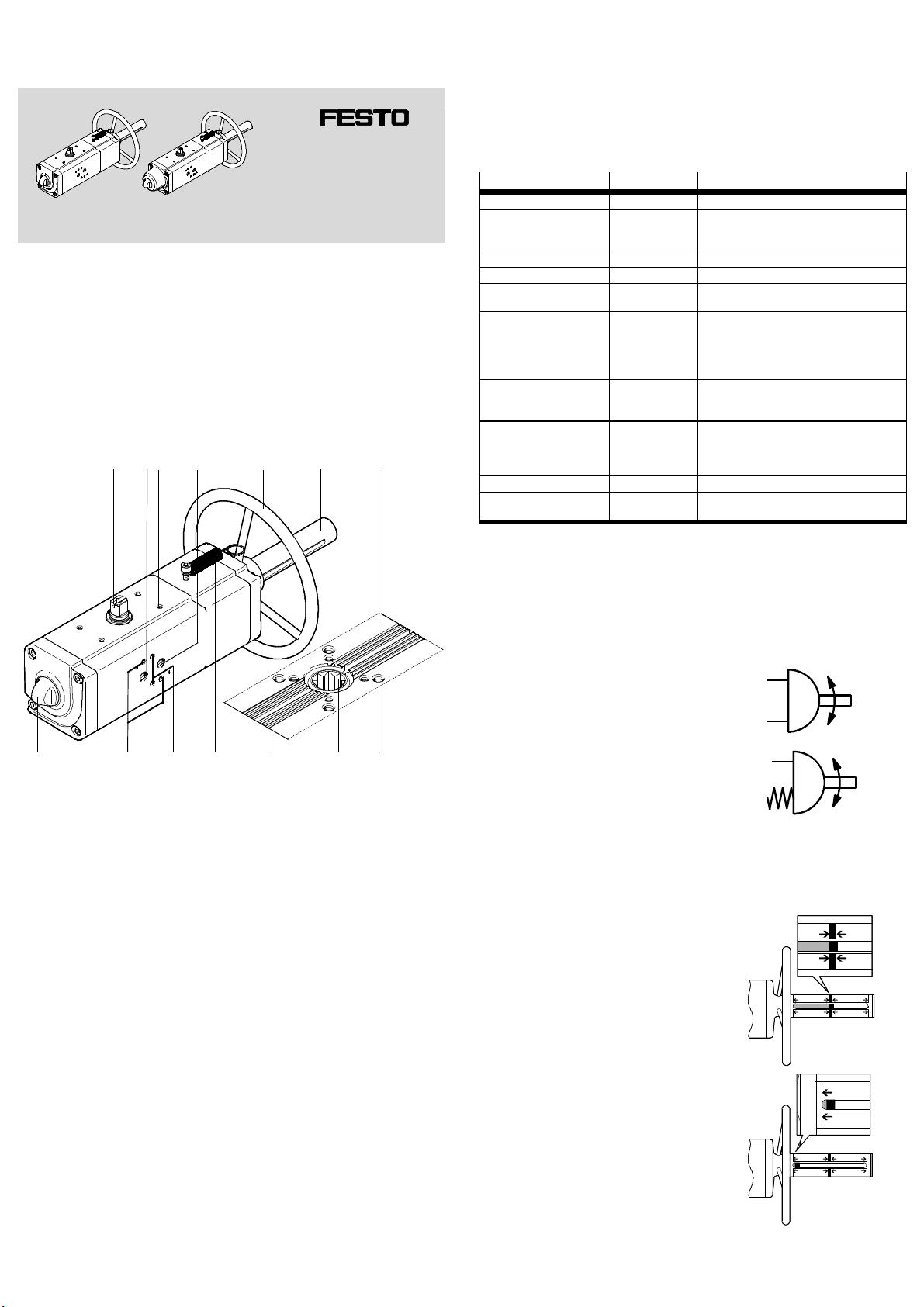
1 Control sections and connections
Example of c onnections on the double-acting quarter turn actuator DAPS:
12
34
5
6
7
The housing of some quarter turn actuators has, on the process valve port side, a
leakage groove ( Fig. 1, aJ ) through which the leakage of an untight process
valve can escape.
The single-acting design with spring return is equipped with different spring forces
for use with different supply pressures.
The DAPS...-MW product version described here is equipped with a handwheel for manual emergency override in a pressureless state.
The product is available in various designs. These operating instructions describe
the following product variants:
Features
Series DAPS- Quarter turn actuator
Size or nominal torque in Nm 0053-
Swivel angle in degrees 090- 90 °
Closing direction R Closes to right
Mode of operation - (without)
Spring strength (with mode
of operation S)
1st flange hole pattern F05
2nd flange hole pattern (without)
Manual emergency override -MW with handwheel
Design (without)
Type code Description
…
1920-
S
(without)
1234-
…
F14
07
…
16
-T6
Nominal torque 53 Nm
…
Nominal torque 1920 Nm
Double-acting
Single-acting
(Omitted for double-acting)
Spring strength for connection pressure 2.8 bar
Spring strength for connection pressure 3.5 bar
Spring strength for connection pressure 4.2 bar
Spring strength for connection pressure 5.6 bar
Flange hole pattern F05
…
Flange hole pattern F14
No second flange hole pattern
Flange hole pattern F07
…
Flange hole pattern F16
Standard design (-20 °C to + 80 °C)
Low temperature (-50 °C to 60°C)
Fig. 2 Type code (e.g. DAPS-0480-090-R-F1012-MW-T6)
aCaD
1 Transmission shaft (shaft groove
shows the process valve position–
open here)
2 Compressed air supply port 2 (A)
3 Four mounting threads – e.g. for
mounting the limit switch or
sensor box
4 Compressed air supply port 4 (B)
5 Handwheel
6 Shield tube with inspection win-
dow
aAaB
89aJ
8 Mountingthread
9 Star-shaped coupling for seating
of the square of a process valve
aJ Leakage groove
aA Locking spring
aB Mounting thread for threaded pin
for aligning the NAMUR valve
aC Mounting thread for pneumatic
NAMUR switching valve
aD Lock nut for retaining the set end
position.
7 View from below – flange to
ISO 5211
Fig. 1
2Design
Quarter turn ac tuators of the DAPS series are compact in design and have simple
and robust mechanics with little wear and tear. The design of the product is dependent on the product design and may differ from the representation shown in
Fig. 1 ( Fig. 1).
Through the housing, a shaft is guided outward on both sides. Through this, the
reaction torque is transmitted to a process valve ( Fig. 1, 9 ) and, if applicable,
a limit switch or sensor box ( Fig. 1, 1 ).
The flange to the process valve is designed in accordance with ISO 5211. Four
mounting threads on the top are used for mechanical attachment of a limit switch
or sensor box ( Fig. 1, 3 ). The housing side has a hole pattern for valve attachment in accordance with VDI/VDE 3845 (NAMUR).
Depending on the version, the DAPS is designed as a single-acting or double-acting
quarter turn ac tuator.
Select suitable accessories (e.g. adapter kits) from the c atalogue
(www.festo.com/catalogue).
3 Function
The piston movement of the DAPS is converted to a rotary movement by means of
yoke kinematics(Scotch yoke). These kinematics are only effective within an angle
of approx. 90°.
For double-acting quarter turn actuators:
Pressurising and venting of the cylinder chambers
cause the piston in the DAPS to move back and forth.
The linear motion of the piston is transformed into a
swivel motion of the transmission shaft.
Fig. 3
For single-acting quarter turn actuators:
Return is through spring force.
Product designs with different spring strengths are
available ( Fig. 2 ).
Fig. 4
The screwed-on processing valve records the moment of reaction of the quarter
turn actuator. The torques permitted in accordance with the technical specifications ( catalogue www.festo.com/catalogue) apply here.
The handwheel can be used to change the position of the actuator when the supply pressure is switched off (manual emergency override).
Neutral position
If the indicator is located centrally , the
handwheel is in a neutral position.
– The piston can be moved freely.
– The actuator can be operated pneumatic-
ally.
Fig. 5
Indicator in left-hand position (inside)
A) Double-acting actuator:
Turning the handwheel anti-clockwise
moves the indicator inwards.
– The process valve opens.
B) Single-acting actuator:
Turning the handwheel clockwise moves the
indicator inwards.
– The process valve closes.
Fig. 6
Page 2
Indicator in right-hand position (outside)
A) Double-acting actuator:
Turning the handwheel clockwise moves the
indicator outwards.
– The process valve closes.
B) Single-acting actuator:
Turning the handwheel anti-clockwise
moves the indicator outwards.
– The process valve opens.
Fig. 7
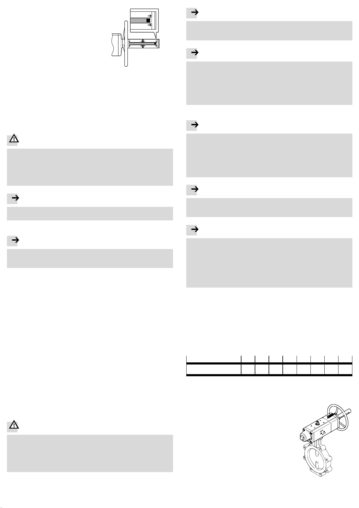
4 Application
The DAPS quarter turn actuator is intended to activate right-closing process
valves, such as ball valves and butterfly valves with a rotation angle from 0° (valve
closed) to 90° (valve open).
It is completely tailored to the requirements of the processing industry and is suitable for control of media-flow process valves in fluid engineering systems.
5 Transport and storage
Ensure the following storage conditions: short storage times in cool, dry, shaded
and corrosion-resistant locations.
War n ing
Danger of c rushing! Danger of shearing!
The DAPS weighs up to about 50.6 kg, depending on the product version.
Body parts can be crushed or cut o ff if the product falls.
• For product versions weighing more than 12 kg, always use suitable load-carrying equipment in order to handle the product safely during transport and
assembly.
Note
• Use only unlubricated compressed air under normal conditions.
The DAPS quarter turn actuator possesses an initial lubrication which suffices
for the complete service life.
Note
Continuous operation at the limits of the specified ambient temperature and
work frequency can reduce the service life of the quarter turn actuator.
• Use lubricated compressed air for continuous operation under extreme conditions. The oil must be chemically inert and must not carbonise.
If lubricated compressed air is used:
The initial lubricationwill be washed out. The quarter turn actuator may then
only be operated with lubricated compressed air.
7 Installation
Note
The following instructions on fitting the DAPS quarter turn actuator onto a processing valve may only be used in the following circumstances:
– The quarter turn actuator is installed in the direction of the tubing.
– If a 2-way process valve is used:
The 2-way process valve is closed.
– If a 3-way process valve is used:
The switchingstatus of the 3-way process valve is known.
Note
Improper handing can cause damage to the product!
• Never use the handwheel to lift the actuator.
6 Requirements for productuse
Note
Improper handling can result in malfunctions.
• Make sure that all the instructions in this chapter are always observed. The
product will then function correctly and safely.
• Compare the maximum values specified in these operating instructions with
your actual application (e.g. pressures, forces, torques, masses, speeds, temperatures). The product can only be used in compliance with the relevant safety
guidelines if the maximum load limits are observed.
• Ensure that all applicable regulations for your location are adhered to, e.g. of
the trade association or national institutions.
• Take into consideration the ambient conditions at the location of use. Corrosive
environments reduce the service life of the product.
• Remove the packaging except for the adhesive labels on the compressed air
supply ports (danger of contamination). The material used in the packaging has
been specifically chosen for its recyclability (exception: oil paper = residual
waste).
• Use the product in its original status, without any unauthorised product modifications.
• Protect the device from pressure fluctuations. Use control valves for regulating
pressure and excess pressure.
• Make sure the c ompressed air is properlyprepared (Technical data
section 12).
• Before carrying out installation, dismantling and maintenance work, switch off
the compressed air supply and vent the actuator. Secure compressed air supply
against acc idental restarting.
• Never remove the end cap, shield tube or handwheel.
• Never use a wrench to operate t he transmission shaft by hand.
• Never use levering tools to operate the handwheel.
Danger
In the case of single-acting DAPS, high spring forces (mechanically stored energy) are at work inside the product.
Parts can be ejected and cause serious personal injuries if the end cap is dismounted.
• Never remove the end cap!
• Return the product to Festo if defective or for service.
Note
If a 3-way processing valve is used:
• Align the quar ter turn actuator so that the port openings for a NAMUR valve
facethesidewithouttubing.
Note
Outflowing processing medium must not penetrate into the quarter turn actuator.
The housing of some quarter turn actuators has a leakage groove on the process
valve port side. If the processing valve leaks, the leakage can flow through the
open groove.
• For housings with a leakage groove, make sure the groove is not sealed. In
this way you can be sure that neither processing medium nor escaping air
from the processing valve can penetrate into the quarter turn actuator.
The DAPS quarter turn actuator can be mounted with or without an adapter bridge.
If there are high media temperature s in the tubing and in processing valve:
• Use an adapter bridge and also a heat-insulated coupling extension.
7.1 Mechanical installation
• In order to mount the DAPS quarter turn actuator, set the switching shaft of the
process valve so that the desired operating method for opening and closing the
process valve is implemented.
• Note that a processing valve with butterfly valve can only be opened in one direction and closed in the opposite direction.
• Observe the tightening torque:
Thread
Tightening torque [Nm] 5…610 …1120 …2345 ...5080 …85125 …
M5 M6 M8 M10 M12 M14 M16 M20
190 …
200
370 …
390
135
Fig. 8
To mount the quarter turn actuator without an adapter
bridge:
1. Place the quarter turn actuator on the switching
shaft of the processing valve. Make sure here that
the square of the processing valve sits in the starshaped coupling of the quarter turn actuator
without being tilted.
2. Fasten the quar ter turn actuator with 4 corrosionresistant screws and retaining rings (material: VA)
to the connection flange of the process valve.
3. Tighten all the screws in diagonally opposite sequence. Tightening torque Fig. 8.
4. Continued Point 6.
Fig. 9
Page 3

To mount the quarter turn actuator with an adapter
bridge, you need:
– an adapter bridge ( Fig. 10, 1 ),
– a shaft extension( Fig. 10, 2 ).
1. Align the adapter bridge so that its supports are
oriented in the direction of the longitudinal axis of
the quarter turn actuator and, if necessary, the
open side of the adapter bridge towards the pro-
1
2
cess valve.
2. Fasten the adapter bridge to the quarter turn actuator. Do not yet tighten the screws.
3. Guide the shaft extensionthrough the adapter
bridge into the star-shaped coupling on the bot-
Fig. 10
tom of the quarter turn actuator. Make sure that
the shaft extension sits in the coupling without
being tilted.
4. Fasten the quarter turn actuator with adapter bridge and shaft extensionto the
connection flange of the process valve. Make sure here that the square of the
processing valve sits in the shaft extension without being tilted.
5. Tighten all the screws in diagonally opposite sequence.
Tightening torque Fig. 8.
After fitting the quarter turn actuator:
6. Check that the quarter turn actuator turns in the required direction of rotation
and whether the processing valve assumes the required position.
7. If the quarter turn actuator does not turn in the required direction of rotation:
Carry out the following modification:
8.1 Adjustment of the end positions
Some product variants offer the possibility to adjust one or even both end positions of the DAPS within narrow limits in order to influence the closing or opening
angle of the mounted process valve. During adjustment of the end positions, observe the permissible adjustment range of the DAPS used ( section 12, end
position adjustment range).
Note
Product variants without specification of an adjustment range have no possibility
for setting end positions, e.g. all product variants made of stainless steel
(DAPS-...-CR).
The now following description for end position setting refers to the following sizes
in the designs “Standard” and “Low temperature” (-T6):
– DAPS-…-R-…(double-acting); size 0015 up to 1920 ( section 8.2)
– DAPS-…-RS.. (single-acting); size 0015 up to 0960 ( section 8.3)
Information on adjustment of the end position for other sizes can be found, if applicable, in the appendix to the operating instructions supplied with the product
( www.festo.com).
8.2 Adjustment for the DAPS-…-R-… (double-acting) – size 0015 … 1920
For these product variants, the end position that the actuator takes during venting
through port 4 (B) can be adjusted (turn to the right - close process valve).
DAPS..R-… (double-acting)
1. Remove the pneumatic solenoid valve.
2. Turn the solenoid valve 180°.
3. Note the position of the th readed pin for
orientation of a NAMUR valve.
4. Fasten the solenoid valve again.
DAPS..RS-… (single-acting)
1. Remove the screws on the actuator side.
2. Turnthe actuator 90° while it is still connected through the shaft extension or directly to
the processing valve.
3. Tighten th e mounting screws.
7.2 Pneumatic installation
Connections for the compressed air supply
• DAPS quarter turn actuator, double-acting – standard design
– Air supply at port 2 (A) – see Fig. 1 2
Rotation of the switching shaft in an anti-clockwise direction.
– Air supply at port 4 (B) – see Fig. 1 4
Rotation of the switching shaft in a clockwise direction.
• DAPS quarter turn actuator, single-acting with spring return – standard design
– Air supply at port 4 (B): rotational movement anti-clockwise.
– Spring return: rotation clockwise.
Note
For DAPS..RS-… (single-acting):
• Fasten a filter element to the exhaust port 2 (A) to prevent ingress of dirt
particles.
7.3 Installing circuitry
Using the pneumatic switching valves:
• Please note the instructions and explanations in the relevant operating instructions for the pneumatic valves.
8 Commissioning
Note
• Make sure that the operating conditions section 12 lie within the permissible ranges.
The product is ready for operation as soon as it is installed and connected.
• Make sure that a process valve attac hed to the quarter turn actuator can be
switched without hindrance.
• When the supply pressure is switched off, set the handwheel to the neutral
position ( Fig. 5) so that the actuator can be operated pneumatically.
• Slowly pressurize the quarter turn actuator.
123 54
1 Lock nut with sealing ring
2 Threaded rod
4 Port 2 (A)
5 Port 4 (B)
3 Piston
Fig. 11
1. Supply compressed air and close the process valve. The pistons move to the
outer end position. This fixes the threaded rod – dependent on the current setting. Loosening of the lock nut will then not accidentally change the current
setting.
2. Screw down the lock nut with sealing ring. If the threaded rod has loosened,
retighten it by hand until a light resistance is felt.
3. Supply compressed air and open the process valve. The pistons move to the
inner end position.
4. Adjust the end position:
Observe that a complete turn of the threaded rod can change the swivel angle
approx. 1.5° to 3.5° – dependent on the product design.
– Turning the threaded rod clockwise reduces the swivel angle.
– Turning the threaded rod anti-clockwise increasesthe swivel angle.
5. Supply compressed air and close the process valve. The pistons run against the
threaded rod into the outer end position.
6. Check the position of the process valve. To change the swivel angle, repeat
step 3 and 4.
7. Retighten the lock nut on the threaded rod – tightening torque 5 Nm.
8. Check the mode of operationof the quarter turn actuator ( section 8.4)
8.3 Adjustment with the DAPS-…-RS.. (single-acting) – size 0015 to 0960
For these product variants, one of the two end positions of the DAPS can be adjusted – either the end position for right turning or the end position for left turning.
End position for right turning – closing process valve
Note
For the single-acting DAPS, the end position setting for right turning (closing
process valve) does not have a mechanical stop, since the spring disc is not
mechanically connected to the piston. The threaded rod therefore limits only the
path of the return spring so that the piston comes to rest without spring force.
But the piston movement or turning of the shaft is not mechanically limited and
can be continued through external forces.
Page 4

12 34 5
1 Lock nut with sealing ring
2 Threaded rod
3 Piston
Fig. 12
4 Port 2 (A)
5 Port 4 (B)
8.4 Check the mode of operation of the quarter turn actuator
• Check in cyclical tests, through alter nating pressurisation and, if necessary,
venting, whether the quarter turn actuator takes the required positions.
• If necessary, adjust the end positions to the extent the quar ter turn actuator
offers this possibility ( sec tion 8.1).
8.5 Emergency handwheel operation
Before operating the handwheel:
1. Make sure the actua tor is free of pressure.
2. Unhook the locking spring.
3. For the DAPS..R..-F..-MW-T6 “low temperature” version: Remove the protective
cover from the display.
Opening the process valve with the handwheel
DAPS..R-… (double-acting) DAPS..RS-… (single-acting)
• Turn the handwheel anti-clockwise
until the indicator moves inwards
( Fig. 6).
• Turn the handwheel anti-clockwise
until the indicator moves outwards
( Fig. 7).
1. Vent the DAPS and close the process valve. The pistons run to the inside end
position, as a result of spring return, until t he spring disc is held, if necessary, by
the threaded rod. This fixes the threaded rod – dependent on the c urrent setting. Loosening of the lock nut will then not accidentally change the current
setting.
2. Screw down the lock nut with sealing ring. If the threaded rod has loosened,
retighten it by hand until a light resistance is felt.
3. Supply compressed air and open the process valve. The pistons move to the
outer end position.
4. Adjust the end position:
Observe that a complete turn of the threaded rod can change the swivel angle
approx. 1.5° to 3.5° – dependent on the product design.
– Turning the threaded rod clockwise increases the spring travel.
– Turning the threaded rod anti-clockwise reduces the spring travel.
5. Vent the DAPS and close the process valve. The pistons are moved to the inside
end position, as a result of spring force, untilthe threaded rod and the spring
disc delimit the spring travel.
6. Check the position of the process valve. To change the swivel angle, repeat
steps 3 to 6
7. Retighten the lock nut on the threaded rod – tightening torque 5 Nm.
8. Check the mode of operationof the quarter turn actuator ( section 8.4)
End position for left turning – opening process valve
5
12 34
Fig. 14
Closing the process valve with the handwheel
DAPS..R-… (double-acting) DAPS..RS-… (single-acting)
• Turn the handwheel clockwise until
the indicator moves outwards
( Fig. 6).
Fig. 15
Before pneumatically actuating the actuator again:
4. Turn back the handwheel until the indicator is located centrally once again
(neutral position, Fig. 5).
5. Hook in the locking spring again.
6. For the DAPS..R..-F..-MW-T6 “low temperature” version: Replace the protective
cover on the display.
9 Maintenance and care
If used as intended in the operating instructions, the device will be maintenancefree.
10 Disassembly
War n ing
Danger of injury due to uncontrolled movements.
• Switch the tubing system pressureless before dismantling.
1. If necessary, remove any existing limit switches.
2. Remove the pneumatic switching valve.
3. Loosen the screws on the flange of the process valve.
4. Remove the quarter turn actuator (if necessary including mounting adapter and
coupling extension) from the process valve.
11 Troubleshooting
• Please contact Festo.
• Turn the handwheel clockwise until
the indicator moves inwards
( Fig. 6).
1 Lock nut with sealing ring
2 Threaded rod
3 Spring disc
Fig. 13
1. Supply compressed air and open the process valve. The pistons move to the
outer end position. This fixes the threaded rod – dependent on the current setting. Loosening of the lock nut will then not accidentally change the current
setting.
2. Screw down the lock nut with sealing ring. If the threaded rod has loosened,
retighten it by hand until a light resistance is felt.
3. Vent the DAPS and close the process valve. The pistons move to the inner end
position.
4. Adjust the end position:
Observe that a complete turn of the threaded rod can change the swivel angle
approx. 1.5° to 3.5° – dependent on the product design.
– Turning the threaded rod clockwise reduces the swivel angle.
– Turning the threaded rod anti-clockwise increasesthe swivel angle.
5. Supply compressed air and open the process valve. The pistons run against the
threaded rods into the outer end position.
6. Check the position of the process valve. To change the swivel angle, repeat
steps 3 to 6.
7. Retighten the lock nut on the threaded rod – tightening torque 5 Nm.
8. Check the mode of operationof the quarter turn actuator ( section 8.4)
4 Piston
5 Adjustment range of the outer end
position (see technical data)
Page 5

12 Technical data
General technical data
Operating medium Compressed air according to ISO8573-1:2010 [7:4:4]
Note about the
operating medium
Ambient temperature [°C] –20 … +80 –50 … +60
Swivel angle [°] 90
Mounting position Any
Valve connection
corresponding to
standard
Pneumatic connection
– DAPS-0053..RS to
DAPS-0180..RS..
– DAPS-0106..R- to
DAPS-0360..R-..
– DAPS-0240..RS to
DAPS-0960..RS..
– DAPS-0480..R- to
DAPS-1920..R-..
Standard connection
to the process valve
CE marking
(see declaration of
conformity
www.festo.com)
1) Certification-specific special documentation and the documentation of the se nsors must be considered
www.festo.com
Operating conditions DAPS..RS-…-MW..
Nominal operating
pressure
Operating pressure
– DAPS..R– DAPS..RS1-...
– DAPS..RS2-...
– DAPS..RS3-...
– DAPS..RS4-...
End-position adjusting
range at 0°
End-position adjusting
range at 90°
1) Minimum operating pressures vary for single-acting quarter turn actuators depending on spring quantity
2) Exceptions for devices with special marking
1)2)
DAPS-...-MW DAPS-...-MW-T6
Operation with lubricated medium possible (in which case
lubricated o peration will always be required)
Ester oil < 0.1 mg/m³, corresponds to ISO 8573:2010 class [-:-:2]
VDI/VDE 3845 (NAMUR)
G1/8
G1/4
ISO 5211
in accordance with EU Explosion Protection Directive (ATEX)
DAPS..R-…-MW..
(single-acting)
0053 … 1920
[bar] 5.6
[bar]
2.8 ... 8.4
3.5 ... 8.4
4.2 ... 8.4
5.6 ... 8.4
[°] One end position adjustable;
-1 … +9
[°] One end position adjustable;
81 … 91
(double-acting)
0053 … 1920
1 ... 8.4
-1 … +9
-
1)
Required manual force
1)
[N]
DAPS-0053-… 13.9 –
DAPS-0090-... 22.2 –
DAPS-0106-... – 13.9
DAPS-0120-... 27.3 –
DAPS-0180-... 33.7 22.2
DAPS-0240-... 41.7 27.3
DAPS-0360-... 54.4 33.7
DAPS-0480-... 64.3 41.7
DAPS-0720-... 68.5 54.4
DAPS-0960-... 81.3 64.3
DAPS-1440-... – 68.5
DAPS-1920-... – 81.3
1) Required force to overcome the nominal torque during operation of the handwheel
Number of revolutions1)DAPS..RS-…-MW..
DAPS-0053-… 13 –
DAPS-0090-... 16 –
DAPS-0106-... – 13
DAPS-0120-... 18 –
DAPS-0180-... 15 16
DAPS-0240-... 16 18
DAPS-0360-... 19 15
DAPS-0480-... 20 16
DAPS-0720-... 25 19
DAPS-0960-... 26 20
DAPS-1440-... – 25
DAPS-1920-... – 26
1) Number of revolutions re quired for opening and closing with the handwheel, starting from the ne utral
position
DAPS..RS-…-MW..
(single-acting)
(single-acting)
DAPS..R-…-MW..
(double-acting)
DAPS..R-…-MW..
(double-acting)
Information on materials DAPS-...-MW DAPS-...-MW-T6
Seals Nitrile rubber
Polyurethane (PUR)
Fluoro elastomer
Shaft High-alloy ste el (1.4305)
Cover Wrought aluminium alloy
Housing
Screws High-alloy steel
FVMQ
PTFE-reinforced
Switching time [s] per
1)
cycle
DAPS-0053-... 0.89 –
DAPS-0090-... 1.3 –
DAPS-0106-... – 0.41
DAPS-0120-… 1.71 –
DAPS-0180-... 2.70 0.63
DAPS-0240-… 2.2 0.81
DAPS-0360-... 3.6 1.18
DAPS-0480-… 3.8 1.54
DAPS-0720-... 4.7 2.1
DAPS-0960-... 6.3 3.1
DAPS-1440-... – 4.7
DAPS-1920-... – 6.3
1) Average values under idling conditions
Product weight [kg] DAPS..RS-…-MW..
DAPS-0053-… 4.5 –
DAPS-0090-... 6.8 –
DAPS-0106-... – 4
DAPS-0120-... 9 –
DAPS-0180-... 11.7 6
DAPS-0240-... 15.2 8
DAPS-0360-... 19.5 10.2
DAPS-0480-... 28.1 13.2
DAPS-0720-... 38.8 17.8
DAPS-0960-... 50.6 23.8
DAPS-1440-... – 33.6
DAPS-1920-... – 43
1) Product weight is dependent on the spring strength ( www.festo.com/catalogue).
DAPS..RS-…-MW..
(single-acting)
(single-acting)
1)
DAPS..R-...-MW..
(double-acting)
DAPS..R-…-MW..
(double-acting)
 Loading...