


1 Intended use
The bus node CTEU-PN is intended exclusively for use as a
participant (“I/O device”) in a PROFINET network.
The bus node may only be used in its original status
without unauthorised modifications and only in perfect
technical condition.
The specified limit values must be observed here.
The product is intended for use in industrial environ
ments. Outside of industrial environments, e.g. in com
mercial and mixed-residential areas, actions to suppress
interference may have to be taken.
Note...................................
Comply with the legal rules and regulations and
standards, rules of the testing organisations and
insurance companies and national specifications
applicable for the location.
Note...................................
Detailed information on commissioning is provided in
the documentation provided for the primary control
system.
Information about PROFINET:
è www.profinet.com
Information about products from Festo:
è www.festo.com/sp
Note...................................
PI PROFIBUS PROFI NET®, SIEMENS®, SIMATIC®,
TIA Portal® are registered trademarks of the respective
trademark owners in certain countries.
For all available product documentation
è www.festo.com/pk
Qualified personnel
The product may only be commissioned by trained control
and automation technology professionals, who are famili
ar with:
– the assembly, installation, operation and diagnosis of
control systems, networks and field bus systems
– the applicable regulations for accident prevention and
industrial safety
– the documentation for the product.
Service
Consult your local Festo repair service if you have any
technical problems.
2 Safety instructions
Prior to any assembly or installation work, switch off
power supplies, disconnect the compressed air supply
and vent the pneumatics.
For the electrical power supply, only use PELV circuits in
accordance with IEC 60204-1.
Observe the handling specifications for electrostatically
sensitive devices.
Use cover caps to seal unused connections to achieve
the required degree of protection.
Use connection technology with the required degree of
protection.
3 Connections and displays
2
3
1
1 Netzwork connections (network ports TP1/TP2, field
bus interface)
è Section 3.1
2 Status LEDs
è Section 3.2, Section 7
3 Power supply connection (X0)
è Section 3.1.
I-port interface
The I-port interface is located on the underside of the bus
node.
3.1 Ports
Network connections
1)
Pin allocation
1 TD+ Transmitted data
(Transmit Data) +
2 RD+ Received data
(Receive Data) +
3 TD– Transmitted data –
4 RD– Received data –
housing Shield/FEShield/functional earth
2)
1) 2 x socket, M12, 4-pin, D-coded, according to IEC 61076-2; in
stallation guidelines, line specification è Section 4.4
2) Connection to functional earth must be secured over the connec
ted product è Section 4.3, “Equipotential bonding”
Power supply connection
1)
Pin allocation
1 24V Operating voltage
Electronics/sensors
(power system)
PS U
EL/SEN
2 24V Load voltage
Valves/outputs
(Power Load)
PL U
VAL/OUT
3 0V Operating voltage PS U
EL/SEN
4 0V Load voltage PL U
VAL/OUT
5 FE Functional earth2)FE
1) Plug, M12, 5-pin, A-coded, according to IEC 61076-2
2) Connection to functional earth must be secured over the connec
ted product è Section 4.3, “Equipotential bonding”
3.2 Indicators
Status LEDs
1)
Function
PS Status of the operating voltage supply
(power system)
X1
Status of the internal communication between
the bus node and the connected product
(“I-Port Device” 1 and/or “I-Port Device” 2)
2)
X2
NF Network status/network failure
(Network Failure)
TP1
Connection status
(“Link” 1 and/or “Link” 2)
TP2
1) Other informationè Section 7
2) Accessories with two I-port interfaces required to connect up
two products, e.g. the decentralised electric sub-base CAPC
èwww.festo.com/catalogue
4 Assembly, disassembly, installation
Warning................................
Uncontrolled movement of the actuators, loose tubing,
undefined switching states of the electronics.
Injury caused by moving parts, damage to machine and to system.
Before mounting and installation work:
Switch off the power supply
Switch off the compressed air supply.
Vent the pneumatics.
4.1 Mounting the bus node
For mounting the bus node, a product with I-port interface
is required (“I-port device”), e.g. valve terminal with I-port
interface or the decentralised electrical connection box,
type CAPC-... .
Note...................................
Assembly of the bus node on the decentralised electric
sub-base CAPC è Assembly instructions CAPC-...
1.Check seal and sealing surfaces of the bus node and the
product with the I-port interface. Replace damaged
parts.
2.Push the bus node onto the product carefully and
without tilting and press up to the stop.
3.Gently tighten down the self-tapping screws, using ex
isting threads.
4.Tighten the screws with tightening torque:
0.7 Nm ± 0.1 Nm.
4.2 Dismantling the bus node
1.Unscrew the screws.
2.Pull the bus node off without tilting it.
4.3 Connecting the power supply
Warning................................
Electrical voltage
Injury caused by electric shock, damage to machine
and to system.
For the electrical power supply, use only PELV circuits
in accordance with IEC60204-1 (Protective ExtraLow Voltage, PELV).
Observe the general requirements IEC60204-1 of
the PELV power circuits.
Only use power sources that guarantee reliable elec
trical isolation of the operating and load voltage in
accordance with IEC60204-1.
Always connect all circuits for operating and load
voltage supplies U
EL/SEN
and U
VAL/O UT
.
Fuse protection
The bus node also supplies operating and load voltage to
products connected via the I-port interface.
Secure operating voltage U
EL/SEN
and load voltage
U
VAL/O UT
separately.
Take due account of the current consumption of con
nected products during design and protection of the
power supply.
Observe power rating of power supply (no bus node-in
ternal overload protection for the connected products)
è Section 10.
Ensure correct polarity (no bus node-internal reverse
polarity protection for the connected products).
Potential equalisation (earthing measures)
Connect the functional earth (FE) connections of the
connected products to the earth potential with a short
conductor with the greatest possible cross section
( 4 mm
2
Cu).
Note...................................
Functional test
– The PS LED lights up when operating voltage is ap
plied (within permitted range).
–LED X1 or X2 lights up green if a product with an I-por t
interface is co nnected up correctly (è Section 7).
4.4 Connecting to the network
Installation guidelines
Warning................................
Electrical voltage
Injury caused by electric shock, damage to machine
and to system.
For the electrical power supply to all PROFINET net
work participants (“IO Devices”) and other network
components (e.g. on switches and routers) only use
PELV circuits in accordance with IEC60204-1.
Note...................................
Data transmission errors
Malfunction:
If installation has not been carried out correctly and if
high baud rates are used, data transmission errors may
occur, e.g. as a result of signal reflections and attenu
ations.
Connect screening to all network cables
Wherever possible, only ground screening once (“star
topology”) to prevent ground loops
Observe installation guidelines for the PROFIN ET
user organisation (PNO):
è www.profinet.com
è www.profibus.com/download/
è PROFINET installation guidelines
(“PROFINET Installation Guide”,
“Installation Guideline PROFINET Part 2…”)
Observe port and cable specifications:
è PROFINET installation guidelines
è Documentation relating to the control system
è Section 3.1, table “network connections”
è Table “Line specification”.
Note...................................
Unauthorised access to the product can cause damage
or malfunctions.
When connecting the product to a network:
Protect the network from unauthorised access.
Measures for protecting the network include:
– Firewall
– Intrusion Prevention System (IPS)
– Network segmentation
– Virtual LA N (VLAN)
– Virtual private network (VPN)
– Security at physical access level (Port Security).
Further information:
è Guidelines and standards for security in informa
tion technology, e.g. IEC 62443, ISO/IEC 27001.
An access password protects only against accidental
changes.
Use of switches and routers
When using the PROFINET function “Fast Start-up” (FSU):
Only use switches and routers that support the “Fast
Start-up” function.
Connect up network participants (“IO devices”) and
network components via LAN (“wire-bound”)
(no support of “Fast Start-up” by Industrial Wireless
LAN Access Points, IWLAN).
Use of crossover cables
When using patch cables and crossover cables in the
same network:
Ensure that the crossover detection (“Crossover Detec
tion”, “Auto-MDI” or “Autocrossover/Autonegotiation”)
is enabled in the control system.
Note...................................
When using the PROFINET function “Fast Start-up”
(FSU), crossover detection is not available.
Observe notice relating to “Fast Start-up”
è Section 5.10.
Cable specification
Cable Ethernet twisted pair cable, shielded
(Shielded Twisted Pair, STP)
Transmission class
(Link Class)
Category Cat 5
Cable diameter1)6 ... 8 mm
Core cross section 0.14 ... 0.75 mm2;
22 AWG required for max. connection
length between network participants
(End-to-end-Link)
Connection length2)max. 100 m PROFINET-End-to-end-Link
1) When using plug NECUMSD12G4C2ET
2) In accordance with specification for PROF INET networks
(PROFINET installation guideline), based on ISO/I EC 11801,
ANSI/TIA/EIA-568:
è www.profinet.com
è www.profibus.com/download/
Strain relief
When mounting on a moving part of a machine:
Provide the network cable with strain relief.
4.5 Ensuring the protection class
Note...................................
Short circuit
Malfunction or damage to the electronics
Use connection technology (interconnecting cables,
push-in connectors, adapters) with the required de
gree of protection, e.g. plug NECU-M-S-D12G4-C2-ET.
Use cover caps to seal unused connections, e.g.
cover cap ISK-M12:
è Accessories
è www.festo.com/catalogue
Do not remove sealing plug from underside of bus
node.
Only when mounting bus node on the decentralised
electric sub-base CAPC: Replace sealing plug on
underside fo bus node è Assembly
instructions CAPC-...
5 Commissioning, configuration and parameterisation
Commissioning, configuration and parametrisation of the
bus node is dependent on the primary control system
used. The basic approach and required configuration data
are explained in the following sections.
Warning................................
Uncontrolled movement of the actuators, loose tubing,
undefined switching states of the electronics.
Injury caused by moving parts, damage to machine and to system.
Before commissioning, ensure that the connected
products do not perform any uncontrolled
movements.
Observe commissioning notices in the control system
documentation.
No automatic checking of configuration and
parameterisation: The bus node and the connected
products also go into operation if configuration is
incorrect.
5.1 Switching on the power supply
If the control system and network participants have sep
arate voltage supplies, the devices must be switched on
in the following sequence:
1.Switch on power supply to all network par ticipants
(“IO Devices”).
2.Switch on power supply to control system.
5.2 Addressing
PROFINET uses module-oriented addressing, i.e. each
network participant is addressed separately (in contrast
to block-oriented addressing of other fieldbus systems).
The controller uses the following for addressing:
– Fieldbus device names, short fo rm “Device Names”
è Section 5.6
– IP addresses è Section 5.7
– Input/output addresses (I/O addresses) è Section 5.9.
Note...................................
Addressing errors
Incomplete faulty configuration, malfunction, fault in
dication
The address space of the bus node is limited
(è Section 10, Technical data).
Determine the number of assigned inputs and out
puts prior to commissioning.
Basic rules for addressing
– Addressing: Module-oriented, byte-by-byte. Modules
with less than 8 bits occupy 8 bits of address space
and/or 1 byte of address space, but which do not use
all this space.
– The address assignment of the inputs does not depend
on the address assignment of the outputs.
5.3 Import device master file (GSDML file)
A device master file (GSD) in XML format (GSDML) is
needed for configuration, parameterisation and program
ming of the bus node. The GSDML contains all information
required to connect into the hardware configuration of
the control system, e.g. Siemens SIMATIC STEP 7.
Download of the GSDML file
è www.festo.com/sp
1.Enter search term: “GSDML”.
2.Click “Firmware and drivers” tab.
3.Click “File and language versions” link.
4.Transmit file “GSDML-V...-Festo-CTEU-...zip” to the con
trol system and unpack it.
The file contains:
– one or more GSDML files
(GSDML-V...-Festo-CTEU-...xml)
– a symbol file (GSDML-...-...-CTEU.bmp)
– optionally a “Read Me” file with notes on the current
GSDML versions.
Observe comments in the “Readme” file.
Installation of the GSDML file
è Documentation of the control system
After installation of the GSDML file, all available network
participants (“IO devices”, bus nodes) and field devices
(“Field devices”), e.g. products with an I-port interface
appear in the hardware directory of the control system
(“Catalog”).
Example of Siemens SIMATIC S7-1200, TIA portal:
Install GSDML file (“Install general station description
file (GSD)”).
Operating instructions
Original instructions
Network protocol PROFINET
Festo AG & Co. KG
Ruiter Straße 82
73734 Esslingen
Germany
+49 711 347-0
www.festo.com
8067834 [8067836] 1703a
Bus node
CTEU-PN
5.4 Setting up control system, creating automation
project
è Documentation of the control system
Example of Siemens SIMATIC S7-1200, TIA portal:
1.Open device and network view:
View è Double click “Devices & networks”.
2.Open “Network view”.
3.Open hardware catalog (“Catalog”).
4.Open “System control” (“PLC”) directory.
5.Drag system control (PCL/“CPU”) into the network view.
5.5 Insert PROFINET station (“Station”)
è Documentation of the control system
Example of Siemens SIMATIC S7-1200, TIA portal:
1.Open “Devices & networks” view è Section 5.4).
2.Open “Network view”.
3.Open hardware catalog (“Catalog”).
4.Open “Other field devices” directory:
è “PROFINET IO” è “Valves” è “Festo AG & Co. KG”
è “Festo CTEU-PN”.
5.Select the symbol for the PROF INET station, i.e. of bus
node CTEU-PN and drag it into the network view.
6.Open “Connections” view.
7.Connect bus node CTE U-PN to the control system:
Click bus node symbol, press and hold down button and
drag mouse pointer to system control symbol.
8.Select connection: “Connections” è “PROFI NET IO
system”.
5.6 Assigning a “Device Name”
è Documentation of the control system
With the device name, you can address the bus node and
the connected product (“I-port device”) directly, e.g. in
your automation program.
5.7 Assigning or changing IP address
è Documentation of the control system
In most cases, the control system handles the assignment
of an IP address.
Note...................................
Observe the basic addressing rules for the allocation
of the IP address, e.g. with respect to the use of
private or public address ranges.
Check that the IP address can be used in the automa
tion network.
Ensure that there is no duplication of IP addresses in
use.
5.8 Configuring field devices (“I-port devices;)
è Documentation of the control system
Example of Siemens SIMATIC S7-1200, TIA portal:
1.Open “Devices & networks” view è Section 5.4).
2.Open “Device view”.
3.Open hardware catalog (“Catalog”).
4.Open “Other field devices” directory.
5.Configure field devices:
Drag the symbols for the connected products (“I-port
devices”) into the “Device overview”.
5.9 Changing start addresses of inputs/outputs
è Documentation of the control system
In most cases, the control system handles the assignment
of the input/output addresses and the diagnosis ad
dresses.
5.10 Setting up PROFINET “Fast Start-up” function
è Documentation of the control system
Note...................................
When using the PROFINET “Fast Start-up” function
(FSU), “Crossover Detection”, “Auto-MDI” and
“Autocrossover/Autonegotiation” are not available.
Crossover detection - disable:
– in the hardware configuration of all network
participants
– in the hardware configuration of the network
neighbor (“Partner Port”).
Deactivation of the crossover detection changes
changes the pin allocation of the next network port TP2
to “crossover”.
Select interconnecting cable dependent on pin
assignment of network connection of product
connected to TP2:
– Crossover cables with identical assignment of
ports
– Patch cables with different assignment of ports.
Example of Siemens SIMATIC S7-1200, TIA portal:
1.Call up “Device overview” :
Open “Project navigation” window è Devices
è Device view è Device overview è Module
è CTEU-PN.
2.Click “PN-IO Interface” module.
3.Call up interface options:
Window for “PN-IO Interface [Module]” è Properties
è General è Advanced options è Interface options.
4.Enable interface option “Prioritized start-up (tick
boxes).
5.Call up por t options:
Window “PN-IO Interface [Module]” è Properties
è General è Advanced options è “Port 1 [X1 P1 R]”
and/or “Port 2 [X1 P2 R]” è Port options.
6.Under “Connection”, disable crossover detection
(“Autonegotiation”) on network ports TP1 and TP2.
5.11 Set parameterisation
è Documentation of the control system
You can set the characteristics of connected products
individually using parameterisation (“Module paramet
erisation”), e.g. input debounce time, signal extension
time, product monitoring, (forwarding of diagnostic mes
sages), settings for error situations (“Fail-state” mode).
Parameterisation for “I-port device” 1 (X1) and “I-port
device” 2 (X2) can be set separately.
Parameter
1)
Function
Port settings
2)
Example “Universal device 256DIO”
Tool Change Mode Tool change mode:
– “Tool Change Mode” enabled:
The process data image rigidly assigns
address spaces for input and output
data (addressed) – regardless of which
product is connected (“I-port device”),
meaning that the connected products
(e.g. tools) can be interchanged without
the need for any configuration changes.
– “Tool Change Mode” disabled:
The “I-port device” detected at start-up
is adopted by the PROFINET configura
tion. The assignment (addressing) of in
put and output data in the process data
image depends on the connected
product.
Suppress all dia
gnostic messages
No forwarding of diagnostic messages via
the network
Suppress
diagnostic message
“No load voltage”
No forwarding of diagnostic message
“No load voltage”3) via the network
4)
(“Suppress missing load voltage diagnostic
messages”)
Fail-state The “Fail-state” mode governs the charac
teristics of the bus node and the connected
products in the event of any communica
tion errors arising:
– Reset outputs (“Outputs reset”): The
outputs are reset.
– Outputs “Hold last state” (“Outputs
Hold last state”): The outputs hold their
last state.
The selected setting applies to all outputs.
The “Fail-state” setting also applies to the
“Idle state” operating state:
– The “Idle state” is adopted by the con
trol system on request. At this point, the
control system is in “Stop mode”.
– Input data continue to be transmitted
while the system is in “Idle state”.
I-port device parameter
2)
Example “Universal device 256DIO”
Byte 0 ... Byte 7 Tunneling of product-specific parameters
è Documentation about the connected
product
1) Siemens SIMATIC S7-1200, TIA portal: Module parameter(s)
2) The available parameters depend on the connected product.
3) Monitoring for undervoltage of load voltage power supply to
outputs/valves U
OUT/VAL
(“Undervoltage U
OUT/VAL
”)
4) Diagnostic messages “No load voltage” are only generated once,
whenever the connected product is monitoring load voltage and
reports this status to the bus node.
Note...................................
Functional test
– The LED NF is OFF (subject to fault-free communica
tion between control system and bus node).
– The LED TP1 or TP2 lights up green (è Section 7).
– Siemens SIMATIC S7-1200, TIA portal: In the
columns for “I address” and “O address”
respectively, the address entries are located (start
addresses for the inputs/outputs).
– Check availability of the network participants:
Menu “online” è “Accessible devices” è Check list
ing of available network participants for complete
ness (“Accessible devices in target subnet”).
6 “Identification and Maintenance”
è Documentation of the control system
The “Identification and Maintenance” (I&M) function of
fers uniform, manufacturer-independent access to
product-specific information.
Note...................................
Manually updated I&M details, e.g. about the firmware
and software state of the bus node can differ from the
details on the product nomenclature.
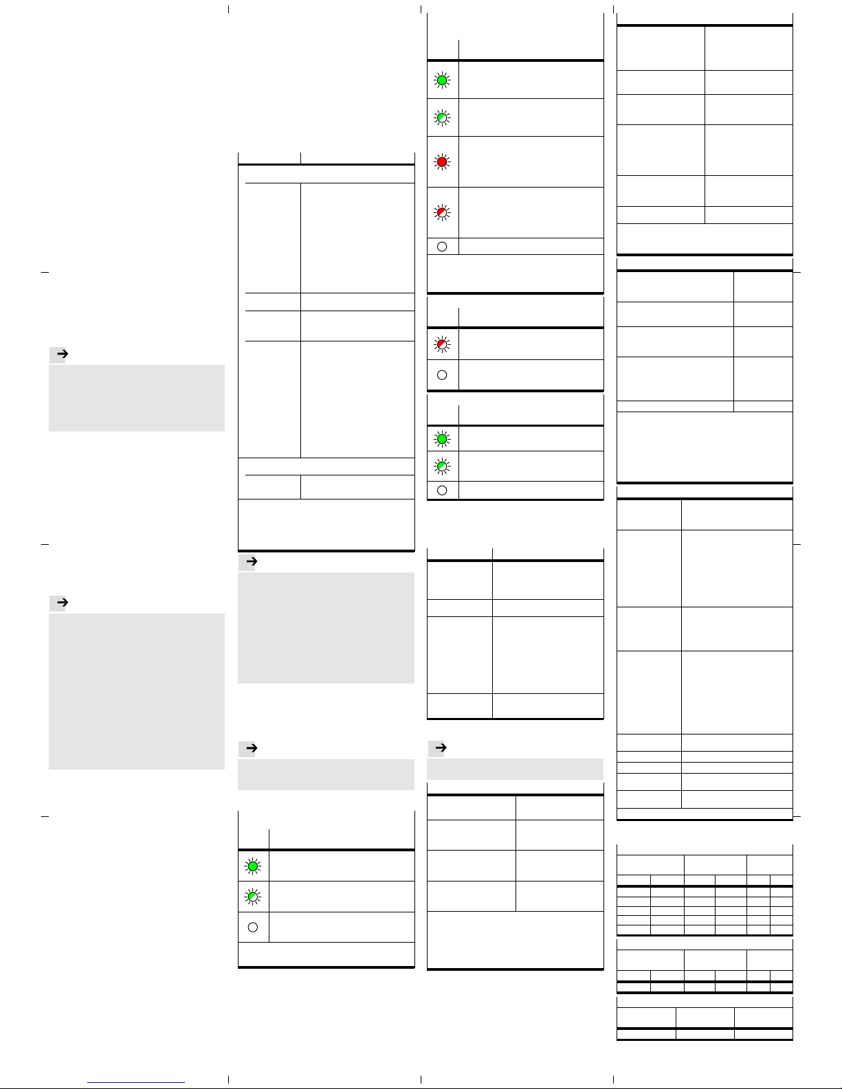
7 Diagnostics
PS – Status of the operating voltage supply
(power system)
LED
display
Status and significance
LED illuminated green:
– normal operating status
– Operating voltage is ON (within permitted range)
– Load voltage is ON (within permitted range)
1)
LED flashes green (flashing frequency: 1 Hz)
– Operating voltage is below the required voltage
– Load voltage is below the required level
1)
– Short circuit at the I-port
1)
LED is off:
– Operating voltage not present
– Operating voltage is below the voltage required for
diagnostic functions
1) This display only relates to the status of the load voltage if the
the connected product is monitoring the load voltage and
reports its status to the bus node.
X1 and X2 – Status of internal communication between
the bus node and the connected product
(“I-port device” 1 or “I-port device” 2)
1)
LED
display
Status and significance
LED illuminated green:
– normal operating status
– “I-port device” 1 or 2 is connected up correctly
– Operating and load voltage are connected (within
permitted range)
2)
LED flashing green:
– Status of diagnostics
– Undervoltage at system or additional power supply
– Connection between the bus node and the “I-port
device” is OK
LED illuminated red:
– “I-port device” is connected up correctly, but the
internal communication is in a fault state
– After start-up, wrong “I-port device” is connected up
(not the “I-port device” specified in the control
system hardware configuration, or a product not
compatible with I-port)
LED flashing red:
– During commissioning, incorrect I-port device
connected (non-I-port-compatible device)
– If only LED X1 flashes red: error in the bus node
– If X1 and X2 flash red simultaneously: no product
connected to the bus node (at least one I-port device
is required)
LED is off:
– No product connected to the bus node
1) Accessory with two I-port interfaces required to connect up two
products
2) This display only relates to the status of the load voltage if the
the connected product is monitoring the load voltage and
reports its status to the bus node.
NF – Network status/network failure
LED
display
Status and significance
LED flashing red:
– Communication error
– Communication between control system and bus
node is malfunctioning or interrupted.
LED is off:
– normal operating status
– Communication between control system and bus
node is OK
TP1/TP2 – Connection status (“Link” 1 or “Link” 2)
LED
display
Status and significance
LED illuminated green:
– normal operating status
– Network connection is OK
Both LEDs, TP1 and TP2 flash green:
– To locate the connected product (“module location”),
e.g. during hardware configuration of control system
or for troubleshooting
LED is off:
– No network connected
8 Maintenance
No specific measures
9 Glossary
Term/abbreviation Function
FSU PROFINET function “Fast Star t-up” also
known as “Prioritized Start-up” or “Fast
reboot”; operating mode of bus node,
assures fast rebooting of network
participants (“IO devices”)
PROFIenergy PROFIenergy facilitates energy
management settings
PROFINET Network and field bus system based on
Industrial Ethernet for data interchange
between a primary control system
(industry PC, PCL or “IO controller”),
network participants (“IO devices”) and
field devices (“Field Devices”), e.g. valve
terminals or drives
è www.profinet.com
è www.profibus.com/download/
è PROFINET System Description,
Technology and Application
PLC Programmable logic controller, also
referred to as system controller or
controller for short (PLC)
10 Technical data
Note...................................
Technical data for the connected products can be ob
tained from the product documentation.
Electrical properties
Protection class through housing
(in accordance with
IEC/EN 60529/EN 60529)
IP65/IP67
1)2)
Protection against electric shock
(protection against direct and
indirect contact to
IEC 60204-1/EN 60204-1)
through the use of PELV circuits
(Protected Extra-Low Voltage)
Separation
Network connections for
operating voltage power supply
U
EL/SEN
Galvanically separated through
transformer (up to 500 V)
Electromagnetic compatibility
(EMC)
3)
– Emitted interference
– Resistance to interference
See declaration of conformity
è www.festo.com
1) Requirement: Bus node mounted completely, plug connector in
the plugged-in status or provided with cover cap.
2) Connected products may only satisfy a lower degree of
protection.
3) The product is intended for use in an industrial environment.
Outside of industrial environments, e.g. in commercial and
mixed-residential areas, actions to suppress interference may
have to be taken.
General mechanical attributes
Vibration and shock resistance
(in accordance with
IEC/EN 60068)
1)
– Vibration (part 2-6)
– Shock (part 2-27)
– Continuous shock (part 2-27)
Severity level (SL)1) for wall or
H-rail mounting
– Wall: SG2; H-rail: SG1
– Wall: SG2; H-rail: SG1
– Wall and H-rail: SG1
Temperature range
2)
– Storage/transport
– Operation
–20 … +70 °C
–5 … +50 °C
Corrosion protection The product is intended for
indoor application in typical
industrial atmosphere: Avoid
condensation.
Materials
– housing
– fibre-optic cable
– Threaded sleeve M12
– Threaded bush M3
– Seals
– Screws
RoHS-compliant
Reinforced polyamide
Polycarbonate
Brass, galvanically nickel-plated
brass,
Nitrile rubber
Galvanised steel
Dimensions
– Width
– Length
– Height
40 mm
91 mm
50 mm
Weight (bus node without cables
and sub-assembly)
94 g
1) Explanation of the severity level è Table “Explanation on
vibration and shock – severity level”
2) Connected products may only satisfy a less extensive
temperature range.
Power supply
Operating voltage for bus node and
connected products
1)
– Nennwert
– tolerance range
24 V DC
18 … 30 V DC
2)
Load voltage for bus node and connected
products
1)
– Tolerance range 18 … 30 V DC
2)
Intrinsic current consumption at nominal
operating voltage 24 V DC
from operating voltage supply for
electronics/sensors (U
EL/SEN
)
Typically 80 mA
(internal electronics)
Power rating of operating and load voltage
power supplies
1)3)
– Bus node on the connected product
(e.g. valve terminal)
– Bus node on the decentralised electric
sub-base CAPC
max. 4 A
max. 2 A
per “I-port device”
4)
Power failure buffering 10 ms
1) Separate and external fuses are required for the operating and
load voltage power supplies (no bus node-internal overload and
polarity reversal protection for the connected products).
2) The tolerance range is dependent on the connected products.
3) Total power rating of operating and load voltage power supplies
PS and PL (residual current), maximum permitted current
consumption of bus node and connected products
4) Total power rating of operating and load voltage power supplies
PS and PL (residual current), maximum permitted current
consumption for each “I-port device”
Network-specific characteristics
Network protocol PROFINET IO:
– based on Industrial Ethernet
– based on the standard Ethernet
protocol (IEEE 802.3)
Supported protocol
characteristics and
protocol functions
(selection)
– Cyclical data exchange “in real time”,
without cycle synchronicity (Real-Time,
RT) or with cycle synchronicity
(Isochronous Real Time, IRT)
1)
– Link Layer Discovery Protocol (LLDP)
– Simple Network Management Protocol
(SNMP)
– Fast Start-up (FSU)
– PROFIenergy
– Shared device
– Media Redundancy Protocol (MRP)
System-specific
functions
– Diagnosis information (system
diagnosis, undervoltage,
communication errors)
– Web server (status of bus node and
connected products, serial number,
configuration)
Specification Selection of directives and norms
regarding PROFINET:
– PROFINET installation guidelines
(“PROFINET Installation Guide”,
“Installation Guideline PROFINET
Part 2…”).
– IEC 61158
– IEC 61784
– IEC 61918
For additional information:
è www.profinet.com
è www.profibus.com/download/
Transmission
technology
Switched Fast EtherCat;
Version 100BaseTX acc. to IEEE 802.3
Transmission rate 100 Mbit/s
Network connections 2 x socket, M12, D-coded, 4-pin
Crossover detection,
auto-negotiation
Auto-MDI
Max. address volume
inputs/outputs
64 bytes E, 64 bytes A,
independent of operating mode
1) IRT is only available via LAN
Explanation on vibration and shock – severity level
Vibration load
Frequency range
[Hz]
Acceleration
[m/s2]
Displacement
[mm]
SL1 SL2 SL1 SL2 SL1 SL2
2 … 8 2 … 8 – – ±3.5 ±3.5
8 … 27 8 … 27 10 10 – –
27 … 58 27 … 60 – – ±0.15 ±0.35
58 … 160 60 … 160 20 50 – –
160 … 200 160 … 200 10 10 – –
Shock load
Acceleration
[m/s2]
Duration
[ms]
Shocks per
direction
SL1 SL2 SL1 SL2 SL1 SL2
±150 ±300 11 11 5 5
Continuous shock load
Acceleration
[m/s2]
Duration
[ms]
Shocks per
direction
±150 6 1000
 Loading...