


Universal bus node
CTEU-PB
Electronics
description
Bus nodes
Type CTEU-PB
Fieldbus protocol
PROFIBUS-DP
Description
575393
en 1208NH
[758863]


Contents and general safety instructions
Original de.......................................
Edition en 1208NH.................................
Designation P.BE-CTEU-PB-OP+MAINT-EN..............
Order no. 575393..................................
© (Festo AG & Co. KG, D-73726 Esslingen, 2012)
Internet: http://www.festo.com
E-Mail: service_international@festo.com
Reproduction, distribution or sale of this document or communication of its contents to others without express authorization is prohibited. Offenders will be liable for damages.
All rights reserved in the event that a patent, utility model
or design patent is registered.
Festo P.BE-CTEU-PB-OP+MAINT-EN en 1208NH English
I

Contents and general safety instructions
PROFIBUS®,SIMATIC®,TORX®,TÜV®and VDE®are registered trademarks of the respective trademark owners in certain countries.
II
Festo P.BE-CTEU-PB-OP+MAINT-EN en 1208NH English

Contents and general safety instructions
Ta b le o f c o n t e n t s
Intended use VII..........................................................
Range of application and certifications VII.....................................
Target group VIII..........................................................
Service VIII...............................................................
Instructions on this description VIII...........................................
Important user instructions IX..............................................
1. Installation 1-1...................................................
1.1 General instructions on installation 1-3................................
1.2 Mounting 1-5......................................................
1.2.1 Connection and display components 1-6........................
1.3 Power supply 1-7..................................................
1.3.1 Power supply connection 1-7.................................
1.4 Setting the DIL switches 1-9..........................................
1.4.1 Removal and mounting of the DIL switch cover 1-9................
1.4.2 Setting the DIL switches 1-10..................................
1.5 Connecting the fieldbus 1-13..........................................
1.5.1 Fieldbus cable 1-13..........................................
1.5.2 Cable specifications 1-13......................................
1.5.3 Fieldbus baud rate and fieldbus length 1-14......................
1.5.4 Fieldbus interface at the bus node 1-15..........................
1.5.5 Connection technology for fieldbus interface 1-16.................
1.5.6 Bus terminal 1-20............................................
1.5.7 Functional test 1-21..........................................
2. Commissioning 2-1................................................
2.1 General remarks on the fieldbus protocol PROFIBUS-DP 2-4...............
2.1.1 Components 2-4............................................
2.1.2 Data exchange with the PROFIBUS-DP fieldbus protocol 2-5........
2.1.3 Brief overview of the function range 2-5........................
2.1.4 Control commands 2-5......................................
Festo P.BE-CTEU-PB-OP+MAINT-EN en 1208NH English
III

Contents and general safety instructions
2.2 Preparing the bus node for configuration 2-7............................
2.2.1 Addressing the bus node 2-7.................................
2.2.2 Modules/devices at I-Port connection 1 and 2 2-7................
2.3 Installation on a higher-level controller 2-10.............................
2.3.1 Device master file (GSD) and symbol files 2-10....................
2.4 Configuration by using process data 2-12...............................
2.4.1 Configuration examples 2-12..................................
2.4.2 Configuration of a DP master 2-16..............................
2.4.3 Bus start-up 2-16............................................
2.4.4 Configuration using a DP master from Siemens as an example 2-17...
2.5 Identification and maintenance 2-26....................................
2.5.1 Overview of the I&M data structures 2-26........................
2.5.2 Load identification properties into the bus node using Step 7 2-27....
2.5.3 Check identification properties using Step 7 2-28..................
2.6 Parameterisation (DP) 2-31...........................................
2.6.1 Parameterisationwhen being switched on (start behaviour) 2-32.....
2.6.2 Equipment parameters 2-32...................................
2.6.3 Parameterisation of the bus node 2-33..........................
2.6.4 Bus node parameters too l change 2-34..........................
2.6.5 Application example for the parameterisation 2-37................
2.7 Communication 2-38................................................
2.7.1 Statuses when communication is established 2-38.................
2.7.2 Status transitions 2-38.......................................
2.8 Fail state behaviour 2-40.............................................
2.9 Switching on 2-42...................................................
2.9.1 Information concerning the switch-on behaviour of the bus node 2-42.
2.9.2 Checklist before switching on 2-43..............................
2.9.3 Switching on the power supply 2-44............................
2.9.4 Normal operating status 2-44..................................
IV
Festo P.BE-CTEU-PB-OP+MAINT-EN en 1208NH English

Contents and general safety instructions
3. Diagnostics 3-1...................................................
3.1 Summary of diagnostics options 3-3...................................
3.2 Diagnostics via LED display 3-4.......................................
3.2.1 Normal operating status display 3-4...........................
3.2.2 PS-LED status display 3-5....................................
3.2.3 Status display X1-/X2-LEDs 3-6...............................
3.2.4 Status display BF-LED 3- 8....................................
3.3 Diagnostics via fieldbus 3-9..........................................
3.3.1 Diagnostic steps 3-9........................................
3.3.2 Overview of diagnostic bytes 3-11..............................
3.3.3 Details for standard diagnostic information 3-13..................
3.3.4 Details of the channel-related diagnostics 3-14....................
3.3.5 Channel-related and extended diagnostic data 3-17................
3.3.6 Event codes of connected equipment 3-17.......................
3.4 Diagnostics via controller or DP master 3-18.............................
3.4.1 Diagnostics for DP masters, general 3-18........................
3.4.2 Diagnostics with Siemens SIMATIC S7 3-18.......................
3.5 Online diagnostics with STEP 7 3-20....................................
3.5.1 Read out diagnostic buffer with STEP 7 (up to V 5.5) 3-20...........
3.5.2 Device-specific diagnostics with STEP 7 (up to V 5.5) 3-22...........
4. Error handling 4-1.................................................
4.1 Fault finding and error elimination 4-3.................................
4.1.1 Check installation 4-3.......................................
4.1.2 Check the power supply 4-3..................................
4.1.3 Restart communication between the bus node and the device 4-4...
4.1.4 Check fieldbus communication 4-5.............................
4.1.5 Check PROFIBUS-DP configuration 4-5.........................
4.1.6 Read out diagnostic messages via controller 4-6.................
Festo P.BE-CTE U-PB-OP+MAI NT-E N en 1208NH English
V

Contents and general safety instructions
A. Technical appendix A-1.............................................
A.1 Technical data A-3..................................................
A.2 Access to the bus node via DPV1 A-7..................................
A.2.1 Reading and writing data records A-7..........................
A.2.2 Data records for DP-master controls, general A-10.................
A.3 Operation with the general DP master A-14..............................
A.3.1 Sending parameterisation data A-14............................
A.3.2 Checking the configuration data A-16............................
A.3.3 Transferring input and output data A-17.........................
A.3.4 Reading diagnostic information A-18............................
A.3.5 Implemented functions and service access points (SAP) A-18........
A.3.6 Transmission times at the master A-19...........................
B. Index B-1.........................................................
VI
Festo P.BE-CTEU-PB-OP+MAINT-EN en 1208NH English

Contents and general safety instructions
Intended use
The bus node CTEU-PB documented in this description has
been designed exclusively for use as a station (slave) on the
PROFIBUS-DP fieldbus.
The bus node may only be used as follows:
–asintended
– in original condition, without unauthorised modifications.
Only the conversions or modifications describe d in the
document at i o n supplied with the product are permitt ed.
– in excellent technical condition.
The limit values specified for pressures, temperatures,
electrical data, torques etc. must be complied with.
Observe the regulations of the trade associations, German
T echnical Control Board (TÜV), VDE stipulations or corresponding national laws and regulations.
Range of application and certifications
The product fulfils the requirements of EU directives and is
marked with the CE marking.
Standards and test values which the product complies with
and fulfils can be found in the Technical appendix. The
product-relevant EC directives can be found in the declaration
of conformity.
Festo P.BE-CTE U-PB-OP+MAI NT-E N en 1208NH English
Certificates and declarations of conformity for this product
can be found at www.festo.com.
VII

Contents and general safety instructions
Targe t gro up
This description is intended exclusively for technicians
trained in control and automation technology who have
experience in installing, commissioning, programming and
diagnosing programmable lo gic controllers (PLCs) and
participants on the PROFIBUS-DP fieldbus.
Service
Please consult your local Festo Service if you have any technical problems.
Instructions on this description
This description includes specific information about the configuration, parameterisation, commissioning, programming
and diagnostics of the bus node with the PROFIBUS-DP fieldbus protocol.
Information for mounting the bus node on the CAPC-... electrical connection box can be found in the assembly instructions supplied with the electrical connection box.
Information about other bus nodes and components of the
CTEU… product family can be found in the product documentation for the respective product.
VIII
Festo P.BE-CTEU-PB-OP+MAINT-EN en 1208NH English
Contents and general safety instructions
Important user instructions
Danger categories
This description includes instructions on the possible dangers
which can occur if the product is used incorrectly. These
instructions are marked with a signal word (Warning, Caution,
etc.), printed on a shaded background and marked
additionally with a pictogram.
A distinction is made between the following danger warnings:
Warning
... means that failure to observe this instruction may result
in serious personal injury or material damage.
Caution
... means that failure to observe this instruction may result
in personal injury or material damage.
Note
... means that failure to observe this instruction may result
in material damage.
In addition, the following pictogram marks passages in the
text which describe activities with electrostatically sensitive
devices:
Festo P.BE-CTE U-PB-OP+MAI NT-E N en 1208NH English
Electrostatically sensitive devices: Incorrect handling may
cause damage to devices.
IX

Contents and general safety instructions
Marking special information
The following pictograms mark passages in the text which
contain special information.
Pictograms
Information:
Recommendations, tips and references to other information
sources.
Accessories:
Specifications on necessary or useful accessories for the
Festo product.
Environment:
Information on the environmentally friendly use of F esto
products.
Text designations
•
Bullet points denote activities that may be carried out in
any sequence.
1. Numerals denote activities that must be carried out in the
sequence specified.
– Arrowheads indicate general lists.
X
Festo P.BE-CTEU-PB-OP+MAINT-EN en 1208NH English

Contents and general safety instructions
The following product and fieldbus-specific terms and abbreviations are used in this description:
T erm/abbreviation
Bus nodes create the connection to certain fieldbuses/networks, pass on control
CLEAR_DATA This command, sent by the master, resets all outputs of the addressed
DI, DO, DX Digital inputs (DI) or outputs (DO) or digital inputs and outputs (DX)
DIL switches Dual-In-Line switches usually comprise several switch elements that can
DP PROFIBUS protocol for decentralised peripheral equipment, such as
F0
h
Fail state This is a function which can automatically activate the “Hold last state” in
Significance
signals to the connected devices/modules and monitor their functioning.
slave.
be used to make hardware settings.
sensors and actuators, and their cyclical communication functions (data
exchange and diagnostic messages) through DPV0-protocol or acyclic,
need-dependent data exchange and alarm handling through DPV1-protocol.
Hexadecimal numbers are marked by a low-set “h”.
the event of connection errors (program abort or timeout of the fieldbus
connection) and is also designated “fail safe” in some cases.
FREEZE This command, sent by the master, freezes all inputs of the slave. The
GSD General Station Description (or Gerätestammdatei - device master file)
Hold last state defines the status which outputs/valves are to assume after fieldbus
I&M
Load voltage includes the power supply for connected devices and (digital) outputs,
Festo P.BE-CTE U-PB-OP+MAI NT-E N en 1208NH English
slave now sends a constant image of all inputs, independent of their further change in status. The input image is updat ed with each further transmission of the FREEZE command.
A FREEZE command is cancelled with UNFREEZE.
stands for the individual electronic data sheet of the device type. It is
made available by the device manufacturer.
and/or communication errors
stands for ‘Identification and Maintenanc e’ and represents the electronic
name plate of the bus node.
e.g. solenoid coils of valves
XI

Contents and general safety instructions
T erm/abbreviation Significance
Master The master/DP master is an active device that determines the data traffic
in the fieldbus system PROFIBUS-DP and may send messages/commands
without external request if there is a transmission authorisation.
The DP master can be an individual device or part of a programmable logic
controller (PLC).
O, I Digital out put, digital input
OB Output byte
Operating voltage also designated signal voltage : includes the power supply for electronics
and sensors
PLC Programmable Logic Controller (German: Speicherprogrammierbare
Steuerung (SPS))
Power supply Heading term for operating and load voltage supplies
PROFIBUS DP is the PROFIBUS variant for speed-optimised, serial data exchange with
decentralised stations and is performed cyclically with the protocol DPV0.
Slave The slave/DP slave is a passive peripheral device that receives messages/
commands of the master, implements and acknowledges them or responds with a message on request of a master.
Station address Address of the fieldbus station, also designated PROFIBUS address or
station number
Status bits Internal inputs, which supply coded common diagnostic messages
PLC/IPC programmable logic controller/industrial PC, also designated system
controller or controller (German: SPS)
SYNC A SYNC command ca uses all slaves addressed by the master to freeze
their own output data and buffer the data transferre d from the master,
which will be switched through to the physical outputs at the next SYNC
command.
A SYNC command is cancelled with UNSYNC.
Tab. 0/1: Terms and abbreviations
XII
Festo P.BE-CTEU-PB-OP+MAINT-EN en 1208NH English

Installation
Chapter 1
Installation
Festo P.BE-CTE U-PB-OP+MAI NT-E N en 1208NH English
1-1

1. Installation
Ta b le o f c o n t e n t s
1. Installation 1-1...................................................
1.1 General instructions on installation 1-3................................
1.2 Mounting 1-5......................................................
1.2.1 Connection and display components 1-6........................
1.3 Power supply 1-7..................................................
1.3.1 Power supply connection 1-7.................................
1.4 Setting the DIL switches 1-9..........................................
1.4.1 Removal and mounting of the DIL switch cover 1-9................
1.4.2 Setting the DIL switches 1-10..................................
1.5 Connecting the fieldbus 1-13..........................................
1.5.1 Fieldbus cable 1-13..........................................
1.5.2 Cable specifications 1-13......................................
1.5.3 Fieldbus baud rate and fieldbus length 1-14......................
1.5.4 Fieldbus interface at the bus node 1-15..........................
1.5.5 Connection technology for fieldbus interface 1-16.................
1.5.6 Bus terminal 1-20............................................
1.5.7 Functional test 1-21..........................................
1-2
Festo P.BE-CTEU-PB-OP+MAINT-EN en 1208NH English

1. Installation
1.1 General instructions on installation
Warning
Danger of injury through uncontrolled movements of connected equipment.
Make sure that electrical and pneumatic equipment are in
a de-energised and pressureless status.
Before working on the pneumatics:
•
Switch off the compressed air supply
•
Vent the valve terminal
Before working on the electrical components, e.g. before
installation or maintenance work:
•
Switch off power supply
In this way, you can avoid:
– uncontrolled movements of loose tubing
– accidental and uncontrolled movements of the connec-
ted actuators
– undefined switching states of the electronics
Caution
The bus node includes electrostatically sensitive devices.
•
Do not touch any electronic components.
•
Observe the handling specifications for electrostatically
sensitive devices.
Festo P.BE-CTE U-PB-OP+MAI NT-E N en 1208NH English
They will help you avoid damage to the electronics.
1-3

1. Installation
Note
Use protective caps or blanking plugs to seal unused connections. You will then achieve protection class IP65.
1-4
Festo P.BE-CTEU-PB-OP+MAINT-EN en 1208NH English

1. Installation
1.2 Mounting
The bus node can be directly mounted on appropriate equipment (e.g. valve terminals with I-Port connection) from Festo
or decentralised on the electrical connection box.
Note
Information on mounting the bus node on the decentralised electrical connection box type CAPC-... can be found
in the assembly instructions that accompany the connection box.
Mo unting on valve terminal For mounting the bus node, a valve terminal from Festo with
I-port connection is required.
Proceed as follows:
1. Inspect the seals and sealing surfaces on bus node and
valve terminal.
2. Plug the bus node onto the valve terminal in the right
position and without tilting.
3. First, lightly screw in the three self-tapping screws with a
Torx screwdriver (size T10). Use existing threads, if available.
4. Tighten the screws with 1.0 Nm.
Festo P.BE-CTE U-PB-OP+MAI NT-E N en 1208NH English
1-5

1. Installation
1.2.1 Connection and display components
The following electrical connection and display components
can be found on the bus node (see Fig. 1/1):
4
1
2
3
1
Power supply connection for bus node
and connected devices, if applicable
(e.g. valve terminal)
2
Fieldbus connection (D-sub plug)
Fig. 1/1: Connection and display components on the bus node
3
DIL switch group 1 and 2
4
Status LEDs (status display/diagnostics chap. 3.2)
1-6
Festo P.BE-CTEU-PB-OP+MAINT-EN en 1208NH English

1. Installation
1.3 Power supply
The bus node has separate operating and load voltage
supplies. The bus node also supplies voltage to equipment
connected via the I-port interface.
Warning
•
For the electrical power supply, use only PELV circuits in
accordance with IEC/EN 60204-1 (Protective Extra-Low
Voltage, PELV).
Also take into account the general requirements for PELV
circuits in accordance with IEC/EN 60204-1.
•
Only use power sources which guarantee reliable electrical isolation of the operating voltage in accordance
with IEC/EN 60204-1.
Through the use of PELV circuits, protection from electric
shock (protection from direct and indirect contact) in accordance with IEC/EN 60204-1 is ensured (Electrical equipment of
machines. General requirements).
1.3.1 Power supply connection
Interface specifications The bus node is equipped with a power supply connection in
accordance with IEC 61076-2-101:
– Round plug connector M12
– Plug (male)
–Acoded
Festo P.BE-CTE U-PB-OP+MAI NT-E N en 1208NH English
–5-pin
1-7

1. Installation
M12 connection, A-coded Pin Allocation Function
3
1 24 V
2
2 24 V
5
3 0V
4 0V
4
1
5 FU
EL/SEN
VAL/OUT
EL/SEN
VAL/OUT
1)
(PS) Operating voltage supply
(PL) Load voltage supply
(PS) Operating voltage supply
(PL) Load voltage supply
Functional earth
1) The connection to functional earth must also be ensured via the connected device or electrical
connection box CAPC-....
Tab. 1/1: Pin allocation of the power supply
For the connection to power supply units or the power supply,
use cables with M12 coupling (socket plug connector),
A-coded, in accordance with IEC 61076-2
( Accessories www.festo.com/catalogue).
1-8
Festo P.BE-CTEU-PB-OP+MAINT-EN en 1208NH English

1. Installation
1.4 Setting the DIL switches
Parameters With the DIL switches, you set the following parameters for
the bus node (incl./excl. connected equipment):
–Operatingmode
– PROFIBUS station address
–Diagnosticsmode
1.4.1 Removal and mounting of the DIL switch cover
T o set the bus node, the cover of the DIL switches must be
removed.
Caution
The bus node includes electrostatically sensitive devices.
•
Do not touch any electronic components.
•
Observe the handling specifications for electrostatically
sensitive devices.
They will help you avoid damage to the electronics.
Proceed as follows:
Dismounting 1. Switch off the power supply.
2. Unscrew the two mounting screws of the transparent cover.
3. Lift off the cover.
Mounting 1. Place the cover carefully on the bus node.
Festo P.BE-CTE U-PB-OP+MAI NT-E N en 1208NH English
Note
•
Make sure that the seal is seated correctly!
2. Tighten the two mounting screws at first hand-tight and
then with a max. torque of 0.4 Nm.
1-9

1. Installation
1.4.2 Setting the DIL switches
Proceed as follows:
1. Switch off the power supply.
2. Remove the DIL switch cover (chap. 1.4.1).
3. Assign a still unused station address to the bus node.
4. Activate/deactivate the diagnostics mode.
5. Set the Fail state characteristics.
6. Mount the DIL switch cover (chap. 1.4.1).
1
DIL switches
1…7:stationaddress
2
DIL switches
8 … 10: reserved
(standard setting:
OFF)
3
DILswitch11:
diagnostics mode
4
DILswitch12:
Fail state mode
Fig. 1/2: DIL switch groups in the bus node
1
23 4
1-10
Festo P.BE-CTEU-PB-OP+MAINT-EN en 1208NH English

1. Installation
Setting the station address with DIL switches
Set the station address of the bus node binary coded using
1
the switch elements 1 … 7 (Fig. 1/2, item
switch. The following station addresses are permissible:
)oftheDIL
Protocol
Address designation Permissible
station addresses
PROFIBUS DP PROFIBUS station
address
1 ... 125
Note
– Station addresses may only be assigned once per high-
er-level master.
– Assign the station addresses in ascending order.
– Assign the station addresses to suit the machine struc-
ture of your system.
Station address examples
Station address “5”
Festo P.BE-CTE U-PB-OP+MAI NT-E N en 1208NH English
DIL switch setting
at the bus node
ON OFF ON OFF OFF OFF OFF
Binary notation 2
Binary number 1 0 1 0 0 0 0
Decimal number 1 0 4 0 0 0 0
0
20+22=1+4=5
1
2
2
2
3
2
4
2
5
2
Fig. 1/3: Station address coding, example 1
6
2
1-11

1. Installation
Station address “38”
DIL switch setting
at the bus node
OFF ON ON OFF OFF ON OFF
Binary notation 2
Binary number 0 1 1 0 0 1 0
Decimal number 0 2 4 0 0 32 0
0
21+22+25=2+4+32=38
1
2
2
2
3
2
4
2
5
2
6
2
Fig. 1/4: Station address coding, example 2
Reserved DIL switches
2
Leave the DIL switches 8 … 10 (Fig. 1/2, item
)onOFF
(standard setting) so that no undesired actions are triggered
in the case of a later extension of function.
Setting the diagnostics mode with DIL switches
You set the device-related diagnostics of the PROFIBUS-DP
with the switch element 11 (Fig. 1/2, item
3
)oftheDIL
switch groups.
If the device-specific diagnostics are activated (ON), devicespecific diagnostic information of the bus node will be sent to
the higher-order master, e.g. short circuit of the outputs or
undervoltage of the valves.
1-12
Setting the Fail state mode with DIL switches
You set the Fail state behaviour of the bus node with the
switch element 12 (Fig. 1/2, item
4
) of the DIL switch
groups. Constellations of Fail state behaviour can be found in
chap. 2.8.
Festo P.BE-CTEU-PB-OP+MAINT-EN en 1208NH English

1. Installation
1.5 Connecting the fieldbus
1.5.1 Fieldbus cable
Note
Faulty installation and high transmission rates may cause
data transmission errors as a result of signal reflections
and attenuations.
•
Always use a bus terminal on both ends of the fieldbus
segment (see chap. 1.5.6)
•
•
•
Note
If the bus node is installed on a movable mounting in a
machine, the fieldbus cable must be provided with strain
relief on the moving part of the machine. Also observe the
corresponding regulations in EN 60204 Part 1.
1.5.2 Cable specifications
Connect the screening continuously to all fieldbus cables
and earth the screening onl y once to avoid ground
loops.
Observe the specifications in the product documentation
of your control system regarding cable type, usable
T-adapters and max. length of branch lines.
In calculating the max. permissible length of the fieldbus
cable dependent on the baud rate used, also consider
the sum of the length of the branch lines.
Festo P.BE-CTE U-PB-OP+MAI NT-E N en 1208NH English
For fieldbus communication, use a twisted, screened two-wire
cable in accordance with the PROFIBUS specification
(EN 50170, cable type A):
1-13

1. Installation
Surge impedance: 135 ... 165 ohms (3 ... 20 MHz)
Capacity per unit length: < 30 nF/km
Loop resistance: < 110 ohms/km
Wire diameter: > 0.64 mm
Wire cross section: › 0.34 mm
2
Fieldbus segment length Precise specifications on the fieldbus segment length can be
found in chap. 1.5.3 and in the product documentation of
your control system.
1.5.3 Fieldbus baud rate and fieldbus length
Note
The maximum permissible fieldbus segment lengths (cable
length without repeater) are dependent on the baud rate
used.
•
Observe the maximum permissible segment length if
you connect the bus node to a fieldbus segment.
•
Avoid branch lines.
The baud rate is specified by the master. It limits the usable
cable lengths (see Tab. 1/2).
Cable length (approximate values) dependent on the data rate (baud rate)
Baud rate
9.6 kBaud Max. 1200 m Max. 500 m
19.2 kBaud Max. 1200 m Max. 500 m
93.75 kBaud Max. 1200 m Max. 100 m
1)
Segment length
2)
Branch line length3)(total)
187.5 kBaud Max. 1000 m Max. 33.3 m
500 kBaud Max. 400 m Max. 20 m
1-14
Festo P.BE-CTEU-PB-OP+MAINT-EN en 1208NH English

1. Installation
Cable length (approximate values) dependent on the data rate (baud rate)
Baud rate
1.5 MBaud Max. 200 m Max. 6.6 m
3…12MBaud Max. 100 m –
1)
The baud rates named here are approximate values and are not supported by all masters.
2)
Trunk line
3)
Drop line
1)
2)
Branch line length3)(total)Segment length
Tab. 1/2: Maximum cable lengths (approximate values)
1.5.4 Fieldbus interface at the bus node
There is a 9-pin sub-D socket on the bus node for connection
to the fieldbus.
This connection is used for the supply line and continuation
of the fieldbus cable. Connect the bus node with the fieldbus
plug from Festo type FBS-SUB-9-GS-DP-B.
Festo P.BE-CTE U-PB-OP+MAI NT-E N en 1208NH English
Note
Before connecting the sub-D plugs of other manufacturers:
•
Replace the two flat screws with bolts
(type UNC 4-40/M3x5) from Festo accessories
( Accessories www.festo.com/catalogue).
1-15

1. Installation
D-sub
socket
1)
Type FBS-SUB-9-GS-DP-B, part no. 532216, IP65
2)
The repeater control signal CNTR-P is a TTL signal.
Pin Fieldbus plug
1)
1
2
3
4
5
6
7
8
9
Housing
from Festo
-
B
-
-
-
A
Clamp strap
Signal
connection
Screening
n.c.
RxD/TxD-P
CNTR-P
DGND
VP
n.c.
RxD/TxD-N
n.c.
Screening
2)
Designation
Connection to functional earth
not connected
Reception/transmitted data P
Repeater control signal
Data reference potential (M5V)
Supply voltage plus (P5V)
not connected
Reception/transmitted data N
not connected
Connection to functional earth
Tab. 1/3: Pin allocation of the fieldbus interface of the bus node
1.5.5 Connection technology for fieldbus interface
2)
Note
Use protective caps or blanking plugs to seal unused connections. You will then achieve protection class IP65.
Connection with fieldbus plugs from Festo
With a fieldbus plug, you connect the bus node conveniently
to the fieldbus without the use of pre-made cable.
Use the fiel dbus plug, type FBS-SUB-9- GS - DP- B from the Fe st o
accesso ri e s ( Accessories www .festo.com/catalogue).
T-TAP function You can disconnect this fieldbus plug from the bus node
without interrupting the fieldbus cable (T-TAP function).
1-16
Festo P.BE-CTEU-PB-OP+MAINT-EN en 1208NH English

1. Installation
DIL switches With the DIL switch in the fieldbus plug, you can switch the
following:
1
Folding cover
with inspection
window
2
Blanking plug if
connection unused
DIL switch setting
OFF Disabled Enabled
ON Enabled Disabled
Note
The fieldbus plug, type FBS-SUB-9-GS-DP-B, switches the
continuing fieldbus line off if the bus terminal is activated.
Bus terminal Continuation
of the fieldbus line
213
Bus out
Bus in
3
Clamp strap for
screened connection
4
Fieldbus incoming (IN)
5
Switch for bus
terminal and continuing fieldbus
6
Fieldbus continued (OUT)
7
Only capacitively
connected
Fig. 1/5: Fieldbus plug from Festo, type FBS-SUB-9-GS-DP-B
Festo P.BE-CTE U-PB-OP+MAI NT-E N en 1208NH English
AB AB
ON
567
4
1-17

1. Installation
Note
The clamp strap in the fieldbus plug from Festo is connected internally only capacitively with the metal housing of
the Sub-D plug. This is to prevent compensating currents
flowing through the screening of the fieldbus line.
Note
Observe the assembly instructions for the fieldbus plug.
Tighten the two mounting screws with max. torque of
0.4 Nm!
Connection with M12 adapter (reverse key coded)
With the M12 adapter, you connect the bus node conveniently
to the fieldbus with the use of pre-made cable. You can disconnect the M12 adapter from the bus node without interrupting the bus line (T-TAP function).
Connection to the fieldbus is made with a 5-pin M12 plug with
PG 9 fitting. Use the second socket for continuation of the
fieldbus.
Use M12 adapters, type FBA-2-M12-5POL-RK from the Festo
accessories ( Accessories www.festo.com/catalogue).
1-18
Festo P.BE-CTEU-PB-OP+MAINT-EN en 1208NH English

1. Installation
M12 adapter
Reverse key , B-coded
2
3
4
FBA-2-M12-5POL-RK
1
1
5
2
4
Bus OUT
Bus IN
Pin no.
Bus IN
1. n.c.
2. RxD/TxD-N
3. n.c.
3
4. RxD/TxD-P
5
5. FE
M12 thread:
functional earth FU, screening
Pin no.
Bus OUT
1. VP (P5V)
2. RxD/TxD-N
3. DGND (M5V)
4. RxD/TxD-P
5. FE
M12 thread:
functional earth FU, screening
Plug with bus terminal required if
connection remains unused.
Tab. 1/4: Pin allocation of the M12 adapters for the fieldbus interface
Connection with fibre-optic cables (FOC)
The PROFIB US-DP interface of the bus node corresponds to
the specification EN 50170-2 and supports the control of network components for fibre-optic cables.
Use fibre-optic cables for transmission in environments subject to heavy interference as well as for extending the working
range at high transmission rates.
Examples for fibre-optic cable network components:
– Siemens Optical Link Module (OLM) for PROFIBUS plus
– Siemens Optical Link Plug (OLP) for PROFIBUS (IP 20)
®
– Harting Han-InduNet
media converter IP 65 (optical data
transmission in the DESINA installati on concept)
Festo P.BE-CTE U-PB-OP+MAI NT-E N en 1208NH English
1-19

1. Installation
1.5.6 Bus terminal
Note
Each fieldbus segment must be terminated at the start and
end to minimise data transmission errors due to signal
reflections and attenuations.
•
To terminate, use a bus terminal network on both ends
of the fieldbus segment (see Fig. 1/6).
•
Never use more than two activated bus terminals within
a fieldbus segment.
Pin 6: Supply voltage VP
390 Ω
Reception/transmitted data
RxD/TxD-P
Reception/transmitted data
RxD/TxD-N
Pin5: Data reference potential DGND
Pin 3
Pin 8
120 nH
220 Ω
120 nH
390 Ω
Fig. 1/6: Circuit diagram of a bus terminal network in
accordance with EN 50170
1-20
Recommendation:
Use the fieldbus plugs from Festo for the bus terminal (see
Fig. 1/5). A bus terminal network that can be connected and
disconnected is integrated in the housing of this plug.
Festo P.BE-CTEU-PB-OP+MAINT-EN en 1208NH English

1. Installation
1.5.7 Functional test
Check the operating status of the bus node using the status
LEDs:
–TheLEDPS is illuminated green when the power supply is
present at both circuits.
–TheLEDsX1 and/or X2 illuminate green when a device is
conne cte d.
Check for error-free communication between bus node and
master using the status LEDs:
–TheLEDBF is not illuminated in the normal operating
status.
See also chap. 2.9.4, Normal operating status.
Festo P.BE-CTE U-PB-OP+MAI NT-E N en 1208NH English
1-21

1. Installation
1-22
Festo P.BE-CTEU-PB-OP+MAINT-EN en 1208NH English

Commissioning
Chapter 2
Commissioning
Festo P.BE-CTE U-PB-OP+MAI NT-E N en 1208NH English
2-1

2. Commissioning
Ta b le o f c o n t e n t s
2. Commissioning 2-1................................................
2.1 General remarks on the fieldbus protocol PROFIBUS-DP 2-4...............
2.1.1 Components 2-4............................................
2.1.2 Data exchange with the PROFIBUS-DP fieldbus protocol 2-5........
2.1.3 Brief overview of the function range 2-5........................
2.1.4 Control commands 2-5......................................
2.2 Preparing the bus node for configuration 2-7............................
2.2.1 Addressing the bus node 2-7.................................
2.2.2 Modules/devices at I-Port connection 1 and 2 2-7................
2.3 Installation on a higher-level controller 2-10.............................
2.3.1 Device master file (GSD) and symbol files 2-10....................
2.4 Configuration by using process data 2-12...............................
2.4.1 Configuration examples 2-12..................................
2.4.2 Configuration of a DP master 2-16..............................
2.4.3 Bus start-up 2-16............................................
2.4.4 Configuration using a DP master from Siemens as an example 2-17...
2.5 Identification and maintenance 2-26....................................
2.5.1 Overview of the I&M data structures 2-26........................
2.5.2 Load identification properties into the bus node using Step 7 2-27....
2.5.3 Check identification properties using Step 7 2-28..................
2.6 Parameterisation (DP) 2-31...........................................
2.6.1 Parameterisationwhen being switched on (start behaviour) 2-32.....
2.6.2 Equipment parameters 2-32...................................
2.6.3 Parameterisation of the bus node 2-33..........................
2.6.4 Bus node parameters too l change 2-34..........................
2.6.5 Application example for the parameterisation 2-37................
2.7 Communication 2-38................................................
2.7.1 Statuses when communication is established 2-38.................
2.7.2 Status transitions 2-38.......................................
2.8 Fail state behaviour 2-40.............................................
2-2
Festo P.BE-CTEU-PB-OP+MAINT-EN en 1208NH English

2. Commissioning
2.9 Switching on 2-42...................................................
2.9.1 Information concerning the switch-on behaviour of the bus node 2-42.
2.9.2 Checklist before switching on 2-43..............................
2.9.3 Switching on the power supply 2-44............................
2.9.4 Normal operating status 2-44..................................
Festo P.BE-CTE U-PB-OP+MAI NT-E N en 1208NH English
2-3

2. Commissioning
2.1 General remarks on the fieldbus protocol PROFIBUS-DP
The CTEU-… product family enables the creation of a decentralised automation system in a PROFIBUS-DP fieldbus network.
2.1.1 Components
1
Higher-order controller (DP master):
e.g. from
SIEMENS
1
2
Fieldbus level:
bus node CTEU
3
Device level:
e.g. valve terminal VTUB-12
4
Drive level:
e.g. Linear module HME
2
3
4
2-4
Festo P.BE-CTEU-PB-OP+MAINT-EN en 1208NH English

2. Commissioning
2.1.2 Data exchange with the PROFIBUS-DP fieldbus protocol
The fieldbus protocol PROFIBUS-DP uses a communication
profile to regulate how data is exchanged among the fieldbus
stations. Cyclical and acyclic data exchange are differentiated
thereby.
2.1.3 Brief overview of the function range
– General communication and diagnostic messages about
cyclical/synchronous data exchange (DPV0)
– Acyclic/asynchronous data exchange (DPV1)
–Diagnostics
–ProcessData
2.1.4 Control c ommands
The operating modes FRE E ZE, SYNC and CLEAR_DATA are
supported by the bus node in accordance with the PROFIBUS-DP standard.
The method of accessing these commands depends on the
controller used. Corresponding information can be found in
your controller’s documentation.
InformationonDPV1commandscanbefoundinchap.A.2in
Appendix A.
Festo P.BE-CTE U-PB-OP+MAI NT-E N en 1208NH English
2-5

2. Commissioning
Caution
The operating mode FREEZE or SYNC is reset automatically:
– when the bus node is switched on or off
– when the fieldbus interface stops
The operating mode FREEZE is also reset automatically
when:
– the bus connection to the bus node is interrupted (with
activated response monitoring in the controller)
FREEZE command
Set All input signals of the bus node are “frozen”. The bus node
now sends a constant image of all inputs to the master. With
each fur ther FR E E ZE command, the input image is updated
and sent again to the master.
Reset Return to normal operation: UNFREEZE command
SYNC command
Set All output signals of the bus node are “frozen”. The bus node
now no longer reacts to modifications to the output image in
the master. With each further SYNC command, the updated
output image is transmitted.
Reset Return to normal operation: UNSYNC command
CLEAR_DATA command
All output signals of the bus node are reset.
2-6
Festo P.BE-CTEU-PB-OP+MAINT-EN en 1208NH English

2. Commissioning
2.2 Preparing the bus node for configuration
A maximum of three modules can be configured: the bus
node itself as well as up to two connected I-Port devices
(e.g. valve terminals).
2.2.1 Addressing the bus node
The bus node has an address space of up to 16 bytes inputs
and 16 bytes outputs:
Max_Data_Len = 32 (20
)
h
The counting mode is module-oriented for inputs and outputs, starting with the device at I-Port connection 1, followed
bythedeviceatI-Portconnection2
2.2.2 Modules/devices at I-Port connection 1 and 2
Enter the identifiers corresponding to the physical sequence
of the modules in your configuration program, starting with
the device at I-Port connection 1, followed by the device at
I-Port connection 2.
Festo P.BE-CTE U-PB-OP+MAI NT-E N en 1208NH English
2-7

2. Commissioning
Electric modules Module
indicator
Designation EN50170 Siemens Inputs Outputs
Bus node CTEU for
PROFIBUS-DP
Valve terminal
CPV10-GE-PT-8 16
valves with I-Port connection
Valve terminal
CPV14-GE-PT-8 16
valves with I-Port connection
Input module CTSL M12 CTSL M12 0x11 16DI 2bytes/16I 0
Input module CTSL M8 CTSL M8 0x11 16DI 2bytes/16I 0
Valve terminal
VTUG-1-16 valves with
I-Port connection
CTEU-PB 0x00 0 – –
CPV10-8 0x21 16DO 0 2bytes/16O
CPV14-8 0x21 16DO 0 2bytes/16O
VAEM-L1-S8-PT
Identifier Allocated address
1)
0x21 16DO 0 2bytes/16O
space
Valve terminal
VTUG-17-32 valves
with I-Port connection
Valve terminal
VTUG-33-48 valves
with I-Port connection
Valve terminal
VTOC-Interlock /
VTUG-Interlock 1-16
valves with I-Port connection
Valve terminal
VTOC-Interlock /
VTUG-Interlock 17-32
valves with I-Port connection
VAEM-L1-S16-PT
VAEM-L1-S24-PT
VAEM-L2-S_
PTL-16
VAEM-L2-S_
PTL-32
0x23 32DO 0 4bytes/32O
0x25 37 0 6bytes/48O
0x13, 0x21 32DI 16DO 4bytes/
(18 used I)
0x33 32DX 4bytes/
(18 used I)
2 bytes/16 O
4 bytes/32 O
2-8
Festo P.BE-CTEU-PB-OP+MAINT-EN en 1208NH English

2. Commissioning
Electric modules Allocated address
Designation OutputsInputsSiemensEN50170
Valve terminal
VTOC-Interlock /
VTUG-Interlock 33-48
valves with I-Port connection
Valve terminal M PA-L
with I-Port connection
with 32 valves
Valve terminal VTUB
with I-Port connection
3-8 valves
Valve terminal VTUB
with I-Port connection
9-16 valves
Valve terminal VTUB
with I-Port connection
17-24 valves
Module
indicator
indicator
VAEM-L2-S_
PTL-48
VMPALEPL-IP032
VTUB-12-8 0x20 8DO 0 1byte/8O
VTUB-12-16 0x21 16DO 0 2 bytes/16 O
VTUB-12-24 0x23 32DO 0 4 bytes/32 O
IdentifierModule
1)
1)
0x13, 0x25 32DI 37 4bytes/(18
0x23 32DO 0 4bytes/32O
space
6bytes/48O
used I)
Valve terminal VTUB
with I-Port connection
24-35 valves
Universal module with
64 inputs and outputs
Universal module with
64 inputs
Universal module with
64 outputs
1)
Module identifier in the hardware configuration of the programming software
VTUB-12-35 0x25 37 0 6bytes/48O
Universal
module
64DIO
Universal
module 64DI
Universal
module
64DO
0x37 55 8bytes/64I 8bytes/64O
0x17 23 8bytes/64I 0
0x27 39 0 8bytes/64O
Tab. 2/1: Module overview and address allocation: bus nodes and examples for digital
input and output modules
Festo P.BE-CTE U-PB-OP+MAI NT-E N en 1208NH English
2-9

2. Commissioning
2.3 Installation on a higher-level controller
2.3.1 Device master file (GSD) and symbol files
A device master file (GSD) is needed for configuration and
programming of the bus node with a programming unit or PC.
The GSD includes all required information for adjustment of
the bus node using configuration and programming software,
e.g. Siemens SIMATIC STEP 7.
Procurement source Current GSD and symbol files can be found on the Festo web-
site at www.festo .com Support/Downloads Search
“GSD”.
GSD files You will require one of the following files for the bus node:
– FEST0D67.GSD (German version)
– FEST0D67.GSE (International version)
For some older controllers, the GSD file can be too large for
the available memory capacity. In this case, contact Festo's
Technical Hotline.
Contact data can be found on the Festo website at
www.festo.c om Contact.
Symbol files Use the following symbol files to represent the bus node and
its statuses in your configuration software:
Normal operating status
Diagnostic case Special operating
status
2-10
File: CTEU_PB.dib File: CTEU_PBD.dib File: CTEU_PBS.dib
T ab. 2/2: Symbol files for configuration software
Festo P.BE-CTEU-PB-OP+MAINT-EN en 1208NH English

2. Commissioning
Publication date Supports
July 2012 Initial version
Tab. 2/3: History of the GSD fil es
Note
GSD files are downward compatible. Always use the latest
GSD file to ensure support of all functions of the bus node.
Installation Install the files by using the configuration software of your
master controller. Please refer to the product documentation
of your software for detailed procedures.
Festo P.BE-CTE U-PB-OP+MAI NT-E N en 1208NH English
2-11
2. Commissioning
2.4 Configuration by using process data
2.4.1 Configuration examples
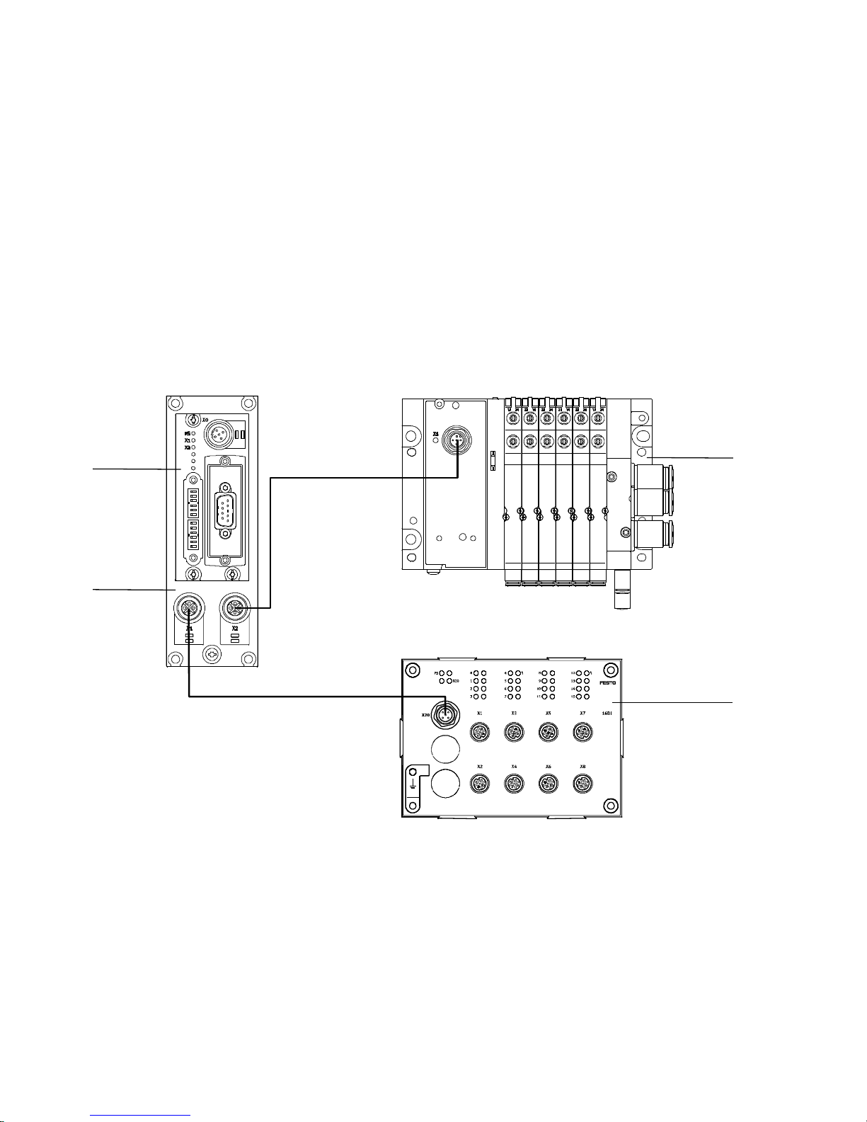
Example 1: Bus node on adapter CAPC-… with valve
terminal MPA-L and input module CTSL-…
1
2
1
Bus node CTEU-PB
2
Electrical connection box CAPC-...
3
Valve terminal MPA-L with I-Port connection
4
Input module CTSL-…
3
4
Fig. 2/1: Configuration example 1:
Bus node with devices at I-Port connection 1 and 2
2-12
Festo P.BE-CTEU-PB-OP+MAINT-EN en 1208NH English

2. Commissioning
Modules Identifier Allocated address
space
Designation
No. Charac-
teristic
Bus node CTEU-PB for
PROFIBUS-DP
Valve terminal M PA-L 1 VMPAL-EPL-
Input module CTSL-… 2 CTSL-D-
1)
Module identifier in the hardware configuration of the programming software
0 CTEU-PB 00
IPO32
16E-M12-5
EN 50170 Siemens Inputs Outputs
1)
h
0x23 32DO 0 4bytes/32O
0x11 16DI 2bytes/16I 0
0 – –
Tab. 2/4: Configuration for example 1
Festo P.BE-CTE U-PB-OP+MAI NT-E N en 1208NH English
2-13

2. Commissioning
1
2
Example 2: Bus node on adapter CAPC-… with valve
terminal VTUB-12
3
1
Bus node CTEU-PB
2
Electrical connection box CAPC-...
Fig. 2/2: Configuration example 2:
Bus node with device at I-Port connection 2
Modules
Designation
Bus node CTEU for
PROFIBUS-DP
Valve terminal
VTUB-12
1)
Module identifier in the hardware configuration of the programming software
No. Charac-
0 CTEU-PB 00
1 VTUB-12-8 0x20 8DO 0 1byte/8O
Identifier Allocated address
teristic
1)
3
Valve terminal VTUB-12 with I-Port
connection
EN 50170 Siemens Inputs Outputs
h
0 – –
space
Tab. 2/5: Configuration for example 2
2-14
Festo P.BE-CTEU-PB-OP+MAINT-EN en 1208NH English

2. Commissioning
1
2
Example 3: Bus node on adapter CAPC-… with valve
terminal CPV
3
1
Bus node CTEU-PB
2
Electrical connection box CAPC-...
Fig. 2/3: Configuration example 3:
Bus node with device at I-Port connection 2
Modules
Designation
Bus node CTEU-PB for
PROFIBUS-DP
valve terminal CPV 1 CPV10-8 0x21 16DO 0 2bytes/16O
1)
Module identifier in the hardware configuration of the programming software
No. Charac-
0 CTEU-PB 00
Identifier Allocated address
teristic
1)
3
Valve terminal CPV with I-Port connection
space
EN 50170 Siemens Inputs Outputs
h
0 – –
Tab. 2/6: Configuration for example 3
Festo P.BE-CTE U-PB-OP+MAI NT-E N en 1208NH English
2-15

2. Commissioning
2.4.2 Configuration of a DP master
The bus node can be controlled by commercially available
programmable logic controllers (PLC) aw well as PCs and industrial PCs with a PROFIBUS-DP interface in accordance with
EN 50170. The corresponding programming and commissioning software of your PLC manufacturer is required for commissioning.
Configuration of the bus node with a PLC from Siemens is
described in chap. 2.4.4.
2.4.3 Bus start-up
In order to commission the mounted and connected bus
node, the master must carry out the following functions in the
corresponding sequence:
1. Request diagnostic information
2. Send parameterisation data (Set_Prm)
For the start parameterisation, the parameter set is
loaded by the master into the bus node. The bus node
distributes the parameters to the connected equipment.
3. Check configuration data (Chk_Cfg)
4. Transfer input and output data (cyclical data exchange,
Data_Exchange)
5. Read diagnostic information (Slave_Diag)
The structure and contents of the individual telegrams are
described in the appendix.
2-16
Note
After each interruption of fieldbus communication, the
parameter set is resent to the bus node by the master.
Festo P.BE-CTEU-PB-OP+MAINT-EN en 1208NH English

2. Commissioning
2.4.4 Configuration using a DP master from Siemens as an example
The configuration examples shown in this chapter are based
ontheuseofaprogrammablelogiccontroller(PLC)Siemens
SIMATIC S7-300 and the configuration and programming software Siemens Step 7, Version 5.5 + SP2. Operation of the
STEP 7 software is assumed to be known in the following.
Note
These instructions refer to the German language version of
the Siemens SIMATIC controller and STEP 7 configuration
and programming software.
Other language versions usually use other designations for
the program and function calls and menu items mentioned
here.
Preparations
Caution
Danger of malfunctions, damage or injuries to people
•
Before commissioning, ensure that the connected elements (e.g. actuators) do not perform any accidental or
uncontrollable movements.
•
If necessary, disconnect the load voltage supply and
compressed air supply.
See also chap. 2.9.2, Checklist before switching on.
Setting up automation project
Festo P.BE-CTE U-PB-OP+MAI NT-E N en 1208NH English
1. Start the Siemens SIMATIC Manager of your Siemens
SIMATIC controller.
2. Create a new project in the SIMATIC Manager: [File] [New…].
2-17

2. Commissioning
3. Enter a project name (e.g. “CTEU-PB”) in the input field
“Name” of the “New” dialogue window and confirm the
input with “OK”.
The new automation project is now set up.
Setting up the controller system (PLC/Master)
4. Select the newly set-up automation project in the left
part of the dialogue window and click on [Insert] - [Station] to select the hardware type of your controller
(e.g. “SIMATIC 300 Station”).
The selected hardware now appears in the right part of
the dialogue window.
5. Open the automation project by clicking on the Plus
symbol in the left part of the dialogue window.
Equip control system (PLC/DP Master)
6. Click on the Station symbol (which is located to the left
of the station name) and double-click on the Hardware
symbol under “Object name” in the right part of the dialogue window.
The “HW Config” hardware configuration window opens.
7. Open the Hardware Catalogue ( 1 ) via the toolbar .
1
2-18
Festo P.BE-CTEU-PB-OP+MAINT-EN en 1208NH English

2. Commissioning
132
4
1
Select control system
2
Insert rack rail
Fig. 2/4: Set up control system (PLC/DP Master) - insert rack rail (Rail)
8. Select your control system (PLC/DP Master) in the Hard-
ware Catalogue (e.g. “SIMATIC 300”, 1 in Fig. 2/4):
Click on the Plus symbol to expand the selection.
9. Open the rack folder (e.g. “RACK-300”, 2 in Fig. 2/4) for
selection of a rack rail.
10. Double click on the rack rail symbol (e.g. “Rail”, 2 in
Fig. 2/4).
A sub-window (with rack rail symbol in the header) opens
in the left area of the HW Config window ( 3 and 4 in
Fig. 2/4).
3
Set up control system in the rack rail
window
Festo P.BE-CTE U-PB-OP+MAI NT-E N en 1208NH English
The sub-window symbolises the rack rail (profile rail) of
your control system. You compile the individual elements
in this sub-window and thus form the basis for your
PROFIBUS automation system.
2-19

2. Commissioning
11. Select your CPU from the Hardware Catalogue (precise
comparison with your hardware required!) and drag the
corresponding element (symbol) into a line of the rack rail
window ( 3 or 4 in Fig. 2/4).
Note: Slot 1 is reserved and cannot be used for the configuration.
The dialogue window “Properties - PROFIBUS interface
DP” opens automatically (see Fig. 2/5).
2-20
Fig. 2/5: Edit the sub-network properties
12. Select the tab “Parameters” or “Network Settings” and
there the station address that you set at the bus node
using DIL switches (see chap. 1.4.2)
Festo P.BE-CTEU-PB-OP+MAINT-EN en 1208NH English

2. Commissioning
Set up sub-network
13. Click on “New...” in the “Properties” dialogue windowto
set up a PROFIB US sub-network (see Fig. 2/5).
14. Edit, if necessary, the “Transmission rate” und “Profile”
entries in the “Parameters” tab (see Fig. 2/5).
15. Click on “OK” in the two “Properties” dialogue windows in
succession to complete the setting of the PROFIBUS subnetwork.
Install GSD and symbol files
Install the GSD and symbol files in the next steps: These must
be reachable via your PC. Source and notes for the selection,
see chap. 2.3.1.
1. Start the installation function via the HW Config menu:
[Options] - [Install GSD File ...].
2. Update the hardware catalogue through the menu commands [Options] - [Update Catalog].
The slaves installed through the GSD file are read into the
hardware catalogue.
3. Open in the hardware catalogue the path PROFIBUS-DP >
Additional Field Devices > Valves > Festo AG und Co. KG >
CTEU-PB.
All modules that can be connected to the CTEU-PB bus
node now appear.
Install bus node as slave
1. Mark the line view of the PROFIBUS sub-network in the
main window (2, see Fig. 2/6).
Festo P.BE-CTE U-PB-OP+MAI NT-E N en 1208NH English
2. Open in the hardware catalogue the path PROFIBUS-DP >
Additional Field Devices > Valves > Festo AG und Co. KG >
CTEU-PB.
2-21

2. Commissioning
3. Selectthemodule“CTEU-PB”.
The dialogue window “Properties - PROFIBUS interface”
opens automatically (3, see Fig. 2/6).
4. Select the tab “Parameters” and there the station address
that you set at the bus node using DIL switches (see
chap. 1.4.2)
5. Click on “OK” in the “Properties” dialogue window to
complete the setting of the PROFIBUS sub-network.
A graphic symbol of the bus node is linked in the main
window with the line view of the PROFIBUS sub-network
(5, see Fig. 2/6).
2-22
Festo P.BE-CTEU-PB-OP+MAINT-EN en 1208NH English

2. Commissioning
2
1
5
3
1
Hardware catalogue call
2
Line view of the PROFIBUS sub-network
3
Module selection in the hardware catalogue
Fig. 2/6: Station selection with STEP 7 - HW Config
4
“Properties” dialogue window
5
With the bus node linked to the
PROFIBUS sub-network
4
Festo P.BE-CTE U-PB-OP+MAI NT-E N en 1208NH English
2-23

2. Commissioning
Configuration of the modular part with STEP 7
Create configuration Fill the configuration table with the device or devices connec-
ted to your bus node (see Fig. 2/7):
1. Click on the symbol of the valve terminal to be configured
in HW Config 1. The configuration table 2 will be displayed under the rack.
2. Open in the hardware catalogue 3 themodule“CTEU-PB”
via the path PROFIBUS-DP > Additional Field Devices > Valves
>FestoAGundCo.KG>CTEU-PB.
3. Pull a bus node into slot 1 of the configuration table.
4. Pull the device connected to I-Port connection 1 into
slot 2 of the configuration table and assign the start address of the inputs or outputs in the “Pro perti es - PR O FIBUS
interface” dialogue window 4.
5. Repeat this step, if necessary , with the second I-Port
device connected to the bus node.
Note
Always pull the device connected to I-Port connection 1 as
a module without gaps into the configuration table first
and only after that do the same with the device connected
to I-Port connection 2.
Modifying the address 1. Double-click on the corresponding line in the configura-
tion table 2.
2. Modify the starting address of the inputs/outputs in the
“Properties - DP Slave” dialogue window 4.
2-24
Festo P.BE-CTEU-PB-OP+MAINT-EN en 1208NH English

2. Commissioning
1
Note
SIEMENS S7-400 controllers reserve up to 4 bytes of addresses for each DP identifier, depending on the version
status.
2
4
1
HW Config
2
Configuration table
Fig. 2/7: Configuration with STEP7 – Hardware catalogue
3
Hardware catalogue
4
“Properties – DP-Slave” dialogue
window
3
Festo P.BE-CTE U-PB-OP+MAI NT-E N en 1208NH English
This concludes the station selection and configuration.
2-25

2. Commissioning
2.5 Identification and maintenance
The I&M function (Identification and Maintenance function)
serves as an electronic name plate of the bus node and offers
uniform, non-proprietary access to device-specific online information via the internet.
2.5.1 Overview of the I&M data structures
Address/
Designation, size Description Use
structure,
I&M0 (65000) Device-specific basic informa-
tion
I&M1 (65001) Informationonthesystem
(32 bytes)
Informationonthelocation(22
bytes)
I&M2 (65002) Informationonthetime
(16 bytes)
I&M3 (65003) Additional information
(54 bytes)
I&M4 (65004) Reserved Support through CTEU-PB:
The manufacturer and the
device with its hardware and
software versions is uniquely
identified.
The user can specify system
identifiers here
The user can specify the installation site here
The user can, for example, specify the installation/mounting
date here
Here the user can specify additional information
no
obligatory/
optional
Obligatory in
all DP-V1
slaves
Optional
Optional
Optional
Optional
Optional
I&M5 …
I&M017
(65005 …
65017)
Reserved for futher I&M Functions
2-26
Support through CTEU-PB:
no
Festo P.BE-CTEU-PB-OP+MAINT-EN en 1208NH English
Optional

2. Commissioning
Address/
structure,
I&M18 …
I&M098
(65018 …
65098)
I&M100 …
I&M199
(65100 …
65199)
Profile-specific I&M functions Support through CTEU-PB: no Optional
Manufacturer-specific I&M
functions
Tab. 2/7: I&M data structures (data records)
– Module-related I&M data are not supported.
– Every data structure always comprises 64 bytes.
– The I&M data structures are read with the “ call service”
from the bus node or written into the device.
DescriptionDesignation, size
Support through CTEU-PB: no Optional
Use
obligatory/
optional
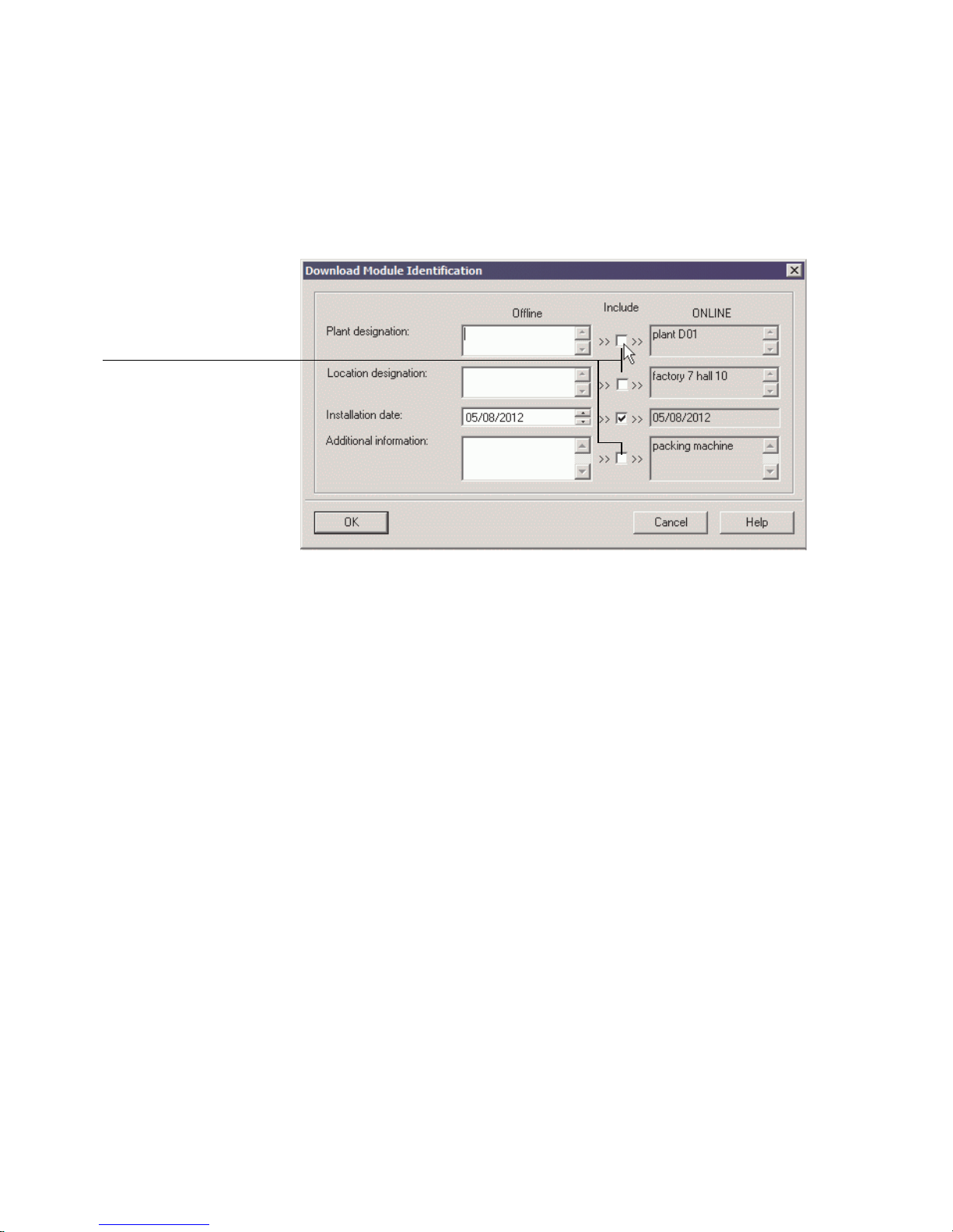
2.5.2 Load identification properties into the bus node using Step 7
1. Mark the bus node in HW Config.
2. Click on [Download Module Identification...] in the [PLC]
menu.
The corresponding dialogue window is displayed (see
Fig. 2/8).
3. Enter your identification properties into the data fields
under “Offline” (example, see Fig. 2/8).
4. Activate the checks under “Include” only for the data
fields for which you wish to load data into the bus node.
Deactivate checks for the already correctly filled-out data
fields in the “ONLINE” field, or they will be overwritten!
Festo P.BE-CTE U-PB-OP+MAI NT-E N en 1208NH English
2-27
2. Commissioning
1
5. Confirm with “OK”.
1
Deactivate checks so that ONLINE fields that have already been filled out are
not overwritten.
Fig. 2/8: Load identification data into the bus node
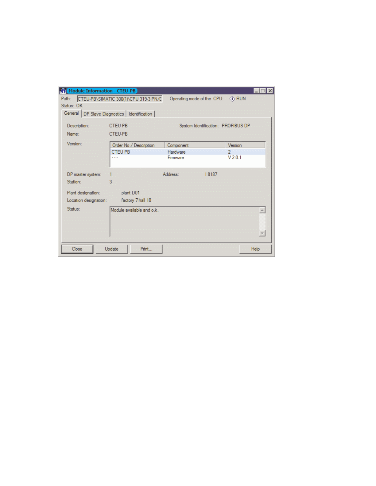
2.5.3 Check identification properties using Step 7
1. Mark the bus node in HW Config.
2. Click on [Module Information...] in the [PLC] menu.
The corresponding dialogue window is displayed
(see Fig. 2/9).
“General” In the “General” tab, you will find the hardware and software/
firmware status of the bus node (see Fig. 2/9) as well as the
specifications entered in the fields “Plant designation” and
“Location designation” (Fig. 2/8).
“DP-Slave Diagnostics” In the “DP-Slave Diagnostics” tab, you will find, if applicable,
diagnostic information about the bus node (see Fig. 2/10,
status: error).
“Identification” In the “Identification” tab, you will find further information,
2-28
such as manufacturer's specifications (see Fig. 2/10) as well
as the specifications entered in the fields “Installation date”
and “Additional information” (Fig. 2/8).
Festo P.BE-CTEU-PB-OP+MAINT-EN en 1208NH English
2. Commissioning
Fig. 2/9: Identification data, “General” tab
Festo P.BE-CTE U-PB-OP+MAI NT-E N en 1208NH English
2-29

2. Commissioning
Fig. 2/10: Identification data, “DP-Slave Diagnostics” and “Identification” tabs
2-30
Festo P.BE-CTEU-PB-OP+MAINT-EN en 1208NH English

2. Commissioning
2.6 Parameterisation (DP)
You can set the characteristics of the bus node individually by
parameterisation. A distinction is made between the following
types of parameters:
Types of parameters
System parameters Fail state Defines the status which digital output sig-
Bus node parameters Tool change See chap. 2.6.4
Equipment parameters Device-specific Influence the characteristics of a specific
Diagnostic memory parameters Influence the operating method of the in-
Parameters Description
nals (outputs and valves) are to assume in
the event of fieldbus communication errors.
module, e.g. monitoring, settings in the case
of error
Channel-specific Influence the behaviour of a specific input or
output channel, e.g. settings of the inputs'
debounce times
ternal diagnostic memory
Tab. 2/8: Types of parameters
Parameter descriptions for I-Port devices can be found in the
product documentation for the respective product if it supports parameterisation.
Festo P.BE-CTE U-PB-OP+MAI NT-E N en 1208NH English
2-31
2. Commissioning
3
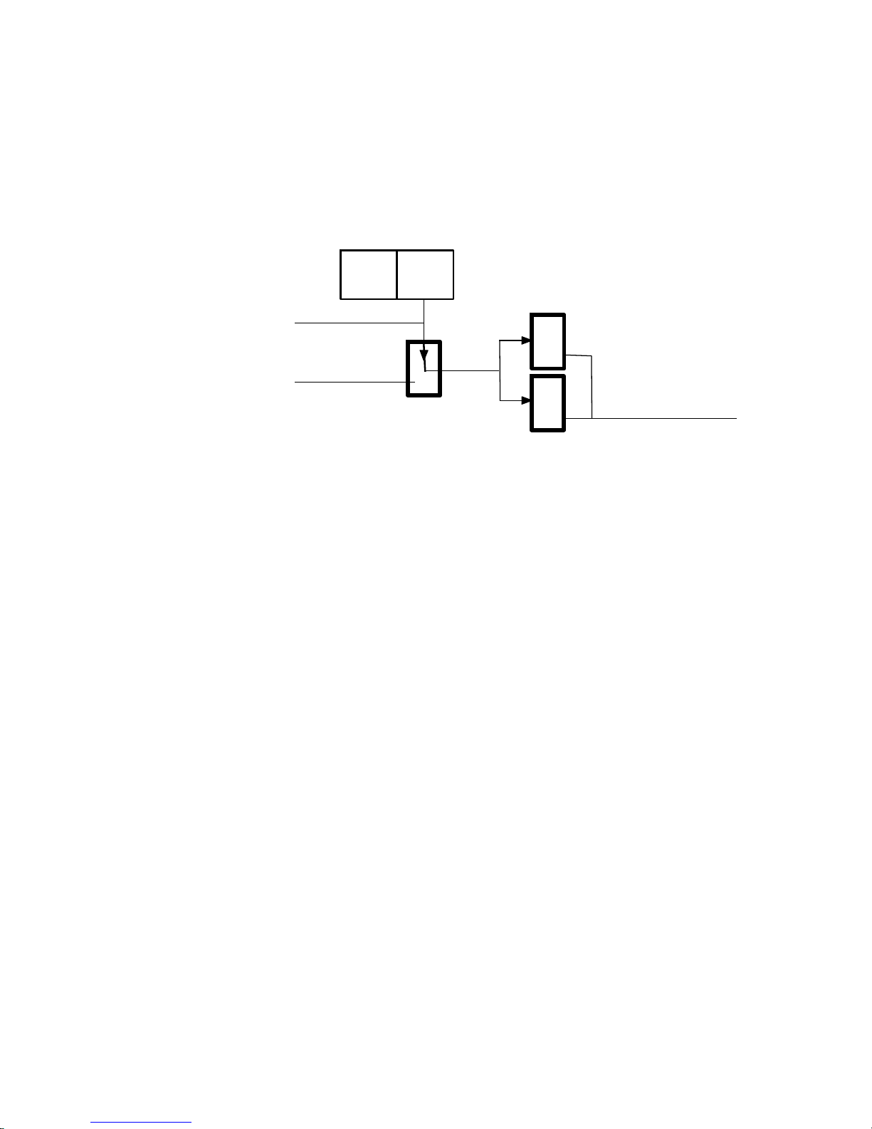
2.6.1 Parameterisationwhen being switched on (start behaviour)
1
Master loads
parameter set into the bus node
2
Bus node distributes parameter
set
3
I-Port devices 1
and 2 receive
parameter set
1
2
PLC/
IPC
DP
master
Fig. 2/11: Sequence of the start parameterisation
When the fieldbus system is switched on, the bus node is
parameterised as “Start parameterisation” through the parameter set stored in the DP master. The bus node then distributes the parameters in a module-oriented manner to the connected equipment.
2.6.2 Equipment parameters
Proceed as follows:
1. Double click in the configuration table on the line of the
module which you wish to parameterise 1.
The corresponding dialogue window is displayed (see
Fig. 2/12).
2. Click on the parameter value which you wish to modify.
A list field with the possible values is opened 4.
2-32
3. Modify the value by clicking on and selecting it and confirm the entry with “OK”.
Festo P.BE-CTEU-PB-OP+MAINT-EN en 1208NH English

2. Commissioning
2
1
1
Connected device
Fig. 2/12: Parameterisation of bus nodes and connected I-Port devices
Note
Module parameters can refer to:
– properties of a complete I-Port device
– properties of an individual channel of an I-Port device.
2
List field with available values
2.6.3 Parameterisation of the bus node
– Diagnostics (DIL swi tch element 11, see chap. 1.4.2)
Festo P.BE-CTE U-PB-OP+MAI NT-E N en 1208NH English
– Fail state (DIL switch element 12, see chap. 1.4.2)
– Tool change mode (software parameters, see chap. 2.6.4)
2-33

2. Commissioning
2.6.4 Bus node parameters tool change
The tool change mode (GSD: “T ool Change Mode”) offers the
option to integrate or replace I-Port devices flexibly. Merely a
universal data range is created, which a device can occupy.
Which equipment is then actually connected is not defined.
As a result, a flexible replacement of different equipment is
possible. In this case, any I-Port devices are recognised
without an error message as long as their real process data
size does not exceed the configured size.
Through a universal module (see Tab. 2/1), a fixed maximum
I/O data length is assigned to each I-Port connection on the
respective module or slot position (Siemens). This ensures
that the right module configuration, i.e. sufficient data length,
is also queried after every switch-on.
In the parameters of the bus node, the tool change mode can
be activated for each I-Port connection individually.
2-34
Festo P.BE-CTEU-PB-OP+MAINT-EN en 1208NH English

2. Commissioning
The following cases of the tool change mode can be differentiated:
Case
Connect/remove or link/separate device in ongoing operation
Tool change mode off Tool change mode on
If a device is separated from the
I-Port connection during operation, the “Device disconnected”
diagnosis becomes active.
This error is automatically reset
as soon as the connection to the
device is restored.
If a device is connected to an
I-Port connection during operation, th e bus node issues an error (“Device wrongly connected”).
This error is automatically reset
as soon as the connection to the
device is separated again.
If a device was already found at
the I-Port connection during
switch-on, the “Device disconnected” diagnosis is active as
long as the connection to the
device is/becomes separated
during operation.
This error is automatically reset
(diagnosis “Device reconnected”) as soon as the connection
to the device is restored.
A fixed address space is reserved in the image table for
both I-Port devices. As soon as a
device is detected at one of the
I-Port connections, its I/O data
are mapped into the image
table.
Diagnostic messages are not
generated when there is no connection to the device nor in case
of configuration errors (e.g. I/O
length of the device is larger
than I/O length of the tool
change mode).
If a device is connected to an
I-Port connection during operation, the device is recognised
but no error message is generated.
Festo P.BE-CTE U-PB-OP+MAI NT-E N en 1208NH English
2-35

2. Commissioning
Case Tool change mode onTool change mode off
Switching on without a connected I-Port device and subsequent connection.
The I-Port connection is not
configured at the DP master
The I-port connection is deactivated und cannot be used.
If no device is connected to the
relevant I-Port connection at
switch-on, no I/O data are
mapped into the image table. As
a result, the “Device configuration failed” diagnosis is output.
The second I-Port connection
then is/becomes inactive as well
and can no longer be used.
This error can only be eliminated
by adjusting the configuration or
connecting an I-Port device to
the bus node and restarting the
system.
Ifadeviceisrecognisedatthe
I-Port connection when the system is switched on, the diagnosis “Device wrongly connected” is
reported. The second I-Port connectionistheninactiveaswell
and can no longer be used.
This error can only be eliminated
by adjusting the configuration or
connecting an I-Port device to
the bus node and restarting the
system.
A fixed address space is reserved in the image table for
each I-Port device. As soon as a
device is detected at an I-Port
connection, its I/O data are
mapped into the image table.
The “Device disconnected” diagnosis is active as long as the
connection to the device is separated during operation. This error is automatically reset as
soon as the connection to the
device is restored.
If a device is detected at this unconfigured I-Port connection, the
second I-Port connection remains active and effective.
2-36
Festo P.BE-CTEU-PB-OP+MAINT-EN en 1208NH English

2. Commissioning
2.6.5 Application example for the parameterisation
In the application example (Fig. 2/13), packages are transported on a fast-moving conveyor belt.
1
Input for 1st
sensor
2
Parameterised input for 2nd
sensor
1
2
1st sensor
2nd sensor
Fig. 2/13: Application example for parameterisation of input debounce time and signal
extension time on the 2nd sensor
For improvement of the signal detection and processing, the
input for the 2nd sensor is parameterised as follows:
– Reduction of the input debounce time from 3 ms (factory
setting) to 0.1 ms: detection of shorter signals is possible.
This parameter is set for the total module.
– Signal extension time set for 50 ms: Secure detection of
the signals through the controller.
The value of this parameter is set for the complete module, but must be activated / deactivated separately for
each input channel.
Festo P.BE-CTE U-PB-OP+MAI NT-E N en 1208NH English
2-37

2. Commissioning
2.7 Communication
After the fieldbus stations are switched on, they all assume
the “waitParam” status and wait for instructions from the
higher-level DP master.
2.7.1 Statuses when communication is established
waitParam In this status, the bus node waits for parameters of the DP
master.
waitConfig In this status, the bus node waits for the set configuration of
the DP master.
DataEx In this status, the bus node is exchanging data (DataEx-
change) with the DP master. User data and diagnostic information can be transmitted thereby.
2.7.2 Status transitions
Power On
4
Application initialization (init)
0
0
3
Waiting for parameters (waitParam)
1
Waiting for configuration (waitConfig)
2
Data exchange (DataEx)
Fig. 2/14: Status transitions (for description see Tab. 2/9)
2-38
Festo P.BE-CTEU-PB-OP+MAINT-EN en 1208NH English

2. Commissioning
0
Description of the status transitions
Status Designation Function
0
1 Check Param OK Checking of the parameters was successful.
2 Check Config OK Checking of the configuration was successful (comparison of the con-
3 Reset communica-
4 Hardware reset After the bus node isrestarted, initialization of the bus node is started
– Initialisation was successful.
figuration set at the DP master with the actually existing configuration
in the bus node).
After timeout or ma lfunctio n at thefieldbus or resetof communication,
tion
fieldbuscommunicationis restarte d, e.g. after the fieldbuscable isunplugged and plugged back in or the D P master is restarted.
anew.
Tab. 2/9: Status transitions – descriptions at Fig. 2/14
Festo P.BE-CTE U-PB-OP+MAI NT-E N en 1208NH English
2-39

2. Commissioning
2.8 Fail state behaviour
Fail state regulates the behaviour of the bus node and the
connected equipment in the event of communication malfunctions.
Parameterisation The behaviour of the bus node is dependent on the DIL switch
setting (see chap. 1.4) and the configured behaviour of the
master in the case of:
– telegram failure
– interruption of the fieldbus line
Depending on the parameterisation, the outputs (valves and
electric outputs) will be switched off (factory setting),
switched on or retain their status (see Tab. 2/10).
Warning
An incorrect status of the valves and outputs can lead to
dangerous situations!
•
Ensure that valves and outputs are put into a safe status
if the stated malfunctions occur.
Note
Please observe the following if the outputs are reset in the
event of fieldbus interruptions or malfunctions:
– Monostable valves move to the basic position
– Bistablevalvesremaininthecurrentposition
– Mid-position valves go into mid-position (pressurized,
exhausted or closed, depending on valve type).
2-40
Festo P.BE-CTEU-PB-OP+MAINT-EN en 1208NH English

2. Commissioning
Behaviour DIL switch: Device: Diagnostics
of the
fieldbus
OK Timeout Off are reset Master controller reports a con-
Timeout OK Off are reset The “X1” and/or X2”-LED on the
of the
connected
device
Timeout Off are reset The “X1” and/or X2”-LED on the
Fail state
switching
position
On remain set
On remain set
On remain set
signals applied by the
bus node
(“Hold last
state”)
(“Hold last
state”)
(“Hold last
state”)
nection error.
The “X1” and/or X2”-LED on the
bus node illuminate red.
“BF”-LED on the bus node is off.
bus node illuminate green.
“BF”-LED on the bus node flashes
red.
bus node illuminate red.
“BF”-LED on the bus node flashes
red.
Tab. 2/10: Constellations of Fail state behaviour
Festo P.BE-CTE U-PB-OP+MAI NT-E N en 1208NH English
2-41

2. Commissioning
2.9 Switching on
This chapter includes fundamental instructions for commissioning the bus node.
Detailed instructions and further information can be found in
the documentation or online help for the controller or control
program that you use.
2.9.1 Information concerning the switch-on behaviour of the bus node
Warning
Danger of injury through uncontrolled movements of connected equipment.
Make sure that electrical and pneumatic equipment are in
a de-energised and pressureless status.
Before working on the pneumatics:
•
Switch off the compressed air supply
•
Vent the valve terminal
Before working on the electrical components, e.g. before
installation or maintenance work:
•
Switch off power supply
In this way, you can avoid:
– uncontrolled movements of loose tubing
– accidental and uncontrolled movements of the connec-
ted actuators
2-42
– undefined switching states of the electronics
Festo P.BE-CTEU-PB-OP+MAINT-EN en 1208NH English

2. Commissioning
Note
The configuration set at the master must agree with the
equipment actually connected at the bus node.
If there are deviations in the configuration, no data exchange takes place between master and bus node (BF-LED
flashes red slowly).
Observe the following instructions about switch-on behaviour:
•
Disconnect the operating voltage from the bus node before replacing equipment, as the configuration is retransmitted from the master at the restart.
•
Equipment must already be connected to the bus node
before switch-on, or an error message will result and no
process data will be exchanged.
•
Special case, tool change mode (chap. 2.6.4):
In this case, any I-Port device is recognised without an
error message as long as the real process data size does
not exceed the configured size.
2.9.2 Checklist before swit ching on
The following conditions must be fulfilled:
– DIL switch settings have been made (see chap. 1.4).
– Fieldbus connecting cables are connected (see chap. 1.5).
– Installation and configuration have been performed com-
pletely (see chap. 2.3 and 2.4).
Festo P.BE-CTE U-PB-OP+MAI NT-E N en 1208NH English
2-43

2. Commissioning
2.9.3 Switching on the power supply
Note
Observe the general commissioning instructions in the
product documentation of your controller.
From the perspective of the bus node, any sequence can be
used to switch on the voltage supply within the fieldbus system.
2.9.4 Normal operating status
After the switch on procedure, the status LEDs indicate the
operating status and correct function of the bus node and the
fieldbus communication.
LED display Status
T ab. 2/11: Status LEDs after switch-on
PS illuminates green when the voltage supply is
established.
X1/X2 illuminates green if the device has been connected correctly and is in the RUN mode.
BF is not illuminated in the normal operating
status.
2-44
Information about diagnostics using the Status LEDs can be
found in chap. 3.2.
Festo P.BE-CTEU-PB-OP+MAINT-EN en 1208NH English

Diagnostics
Chapter 3
Diagnostics
Festo P.BE-CTE U-PB-OP+MAI NT-E N en 1208NH English
3-1

3. Diagnostics
Ta b le o f c o n t e n t s
3. Diagnostics 3-1...................................................
3.1 Summary of diagnostics options 3-3...................................
3.2 Diagnostics via LED display 3-4.......................................
3.2.1 Normal operating status display 3-4...........................
3.2.2 PS-LED status display 3-5....................................
3.2.3 Status display X1-/X2-LEDs 3-6...............................
3.2.4 Status display BF-LED 3- 8....................................
3.3 Diagnostics via fieldbus 3-9..........................................
3.3.1 Diagnostic steps 3-9........................................
3.3.2 Overview of diagnostic bytes 3-11..............................
3.3.3 Details for standard diagnostic information 3-13..................
3.3.4 Details of the channel-related diagnostics 3-14....................
3.3.5 Channel-related and extended diagnostic data 3-17................
3.3.6 Event codes of connected equipment 3-17.......................
3.4 Diagnostics via controller or DP master 3-18.............................
3.4.1 Diagnostics for DP masters, general 3-18........................
3.4.2 Diagnostics with Siemens SIMATIC S7 3-18.......................
3.5 Online diagnostics with STEP 7 3-20....................................
3.5.1 Read out diagnostic buffer with STEP 7 (up to V 5.5) 3-20...........
3.5.2 Device-specific diagnostics with STEP 7 (up to V 5.5) 3-22...........
3-2
Festo P.BE-CTEU-PB-OP+MAINT-EN en 1208NH English

3. Diagnostics
3.1 Summary of diagnostics options
The following possibilities for diagnostics and error handling are
avai lable, depending on the conf i gurat i o n of the bus node :
Diagnostics
Brief description Benefits Detailed
option
LED display The status LEDs display dir-
ectly configuration errors,
hardware errors, bus errors,
etc.
Diagnostics via
PROFIBUS-DP
Diagnostics in accordance
with the PROFIBUS DP
standard
Tab. 3/1: Diagnostics options
1
DIL switch settings:
Off = no diagnostic messages
(default)
On = diagnostics
are sent
Fast “on-site” recognition of
errors
Detailed module-related and
channel-related error detectionintheonlinemodeof
the programming/configuration software and in the PLC
user program.
1
description
Chap. 3.2
Chap. 3.3
Fig. 3/1: DIL switches for diagnostic messages:
Switch element 11 of 12 (counted from the left over both switch groups)
Festo P.BE-CTE U-PB-OP+MAI NT-E N en 1208NH English
3-3

3. Diagnostics
3.2 Diagnostics via LED display
Status LEDs are available on the bus node for diagnosing the
bus node and any connected devices (see Fig. 3/2).
The LEDs can assume the following statuses (sometimes in
different colours):
illuminated flashing off
3.2.1 Normal operating status display
CTEU-specific
1
LEDs
2
Fieldbus-specific
LEDs
3
Reserved
Fig. 3/2: Status LEDs of the bus node
1
2
3
3-4
Festo P.BE-CTEU-PB-OP+MAINT-EN en 1208NH English

3. Diagnostics
3.2.2 PS-LED status display
PS (Power System) – power supply
LED Process Status Meaning/error elimination
LED illuminated green
LED flashing
green
LED is off
ON
OFF
ON
OFF
ON
OFF
Normal operating status:
Operating and load voltage
present and in the permissible range
1)
Undervoltage in operating
or loa d voltage supply
Operating voltage is not
present or not in the permissible range.
–
• Bus node reports undervoltage in
the operating voltage supply
• Connected device reports under-
voltage
at bus nodes
• Check operating voltage supply (pin
1and3)
1) Requirement: the connected device uses and monitors the load voltage
Tab. 3/2: Status displays of the device-specific “PS” LED
1)
in the load voltage supply
Festo P.BE-CTE U-PB-OP+MAI NT-E N en 1208NH English
3-5

3. Diagnostics
3.2.3 Status display X1-/X2-LEDs
X1 or X21)- Internal communication between bus node and device 1 or 2
1)
LED Process Status Meaning/error elimination
ON
OFF
Normal operating status Device is connected correctly to the
bus node.
LED illuminated green
ON
OFF
LED flashing
green
Device diagnostics are running and/or diagnostic
data are on hand.
Data connection between bus node
and device is built up.
• Device diagnostics can be read via
fieldbus communication (if activated via DIL switches on the bus
node)
ON
OFF
LED illuminated red
ON
OFF
LED flashing
red
Device is connected correctly to the bus node, but
internal communication is
faulty.
A connected devi ce was removed after commissioning
Incorrect device connected:
– Device detected that is
notI-Portcompatible
– Non-configured device
detected
• Check I-Port connection: cables,
plug connect ors, signal
transmission (error counter
overrun)
• Restart the bus node (by switching
the power off -> on)
• Use an I-Port-compatible device
(e.g. appropriate valve terminal)
from Festo
• Connect at least one device
• Restart the bus node (by switching
the power off -> on)
If X1 and X2 are flashing
red simultaneously:
– No device connected to
the bus node
– Configuration error
3-6
Festo P.BE-CTEU-PB-OP+MAINT-EN en 1208NH English

3. Diagnostics
LED Meaning/error eliminationStatusProcess
ON
OFF
LED is off
Connection is being established.
No I-Port device is connec-
–
ted to the corresponding
I-Port connection.
1)Electrical connection box CAPC with two interfaces for connecting a second device is required.
Tab. 3/3: Status displays of the device-specific “X1” LED if device 1 is connected and
“X2” if device 2 is connected
Festo P.BE-CTE U-PB-OP+MAI NT-E N en 1208NH English
3-7

3. Diagnostics
3.2.4 Status display BF- LED
BF (bus fault)
LED Process Status Meaning/error elimination
ON
OFF
LED illuminated red
– Hardware error at the bus
node
– Fieldbus communication is
not available or has failed.
• Replace the bus node.
• Contac t Festo Service
– Voltage supply at the master
or the controller has failed.
LED flashing
red
ON
OFF
ON
OFF
– Correct the incorrec t station
number on the bus node or
the controller
– Fieldbus communication is
interrupted and automatic-
• Check station address assign-
• Ready status has been
ally restored.
ON
OFF
Normal operating status Fieldbus communication is built
up. Diagnostics are po ssible.
LED is off
Tab. 3/4: Status displays of the fieldbus-specific “BF” LED
ment
stopped.
3-8
Festo P.BE-CTEU-PB-OP+MAINT-EN en 1208NH English

3. Diagnostics
3.3 Diagnostics via fieldbus
The bus node supports the following diagnostic possibilities
via PROFIBUS-DP in accordance with EN 50170:
– Module-/channel-related diagnostics:
One bit is reserved per module (bus node or connected
device) for displaying a diagnosis.
– Channel-related diagnostics (see chap. 3.3.4):
– Module number
– Module type
3.3.1 Diagnostic steps
– Type of diagnostics (error number)
Fig. 3/3 shows you the steps necessary for diagnostics of the
bus node and of connected equipment.
Festo P.BE-CTE U-PB-OP+MAI NT-E N en 1208NH English
3-9

3. Diagnostics
2nd step:
Evaluation of
the diagnostic
bytes
12304567
1
1
device-specific diagnostics (see
7
Tab. 3/6)
23
Module-related diagnostics
(see Tab. 3/7)
30
Channel-related diagnostics (max.
11 messages)
(see Tab. 3/11)
Bit
1
Station status 1
1st step (evaluation of bit 0
and 2):
Busnodeisvoltage-free,
fieldbus plug is not plugged
in, ...
Projected configuration of the
bus node does not correspond
to the actual configuration.
7bytesVariable 16 byt es
3-10
Fig. 3/3: Diagnostic steps
Note
The device-specific diagnostic information are only sent to
the master if transmission is activated.
•
Inordertodothis,setswitchelement11oftheDIL
switch group to “ON” (see chap. 1.4.2).
In order to commission your fieldbus system, it may be
useful in some cases to switch off the device-specific diagnostics.
Festo P.BE-CTEU-PB-OP+MAINT-EN en 1208NH English

3. Diagnostics
3.3.2 Overview of diagnostic bytes
In the following the diagnostic bytes are represented in four
tables.
Standard diagnostic information
Byte Contents Explanation
1 Station status 1 See Tab. 3/8
2 Station status 2 See Tab. 3/9
3 Station status 3 See Tab. 3/10
4 Diag.Master_add Master address: The address of the master that
parameterised the bus node is entered in this byte.
5 Ident_number high byte Manufacturer identifier high byte (0dh)
6 Ident_number low byte Manufacturer identifier low byte (67h)
7 External diagnostic data Data block of the channel-related diagnostics
Tab. 3/5: Overview of diagnostic bytes: standard diagnostic information
Festo P.BE-CTE U-PB-OP+MAI NT-E N en 1208NH English
3-11

3. Diagnostics
Device-specific diagnostics (16 bytes), (module status DPV1)
Byte Contents Explanation
7 Header For the bus node fixed 04h
8 Typ e For the bus node fixed 81h
9 Slot For the bus node fixed 0
10 Slot For the bus node fixe d 0
11 Module 0 (bit 1 and 2)
...
Module 3 (bit 6 and 7)
12 Module 4…7 like byte 11
13 Module 8…10
(bits 6 and 7 are reserved)
14...22 Reserved –
2 bits per module:
00 = no error (valid user data)
01 = module error (invalid user data)
10 = incorrect module (invalid user data)
11 = module failed or is not on hand (invalid user
data)
like byte 11
h
h
Tab. 3/6: Diagnostic bytes 7 ... 22: device-specific diagnostics (fixed at a length of 16
bytes)
Module-related diagnostics (variable length)
Byte Contents Explanation
1 Header For the bus node fixed 42
2 Module-related diagnostics Specifies the module number with diagnostics.
Tab. 3/7: Module-related diagnostics
3-12
h
Festo P.BE-CTEU-PB-OP+MAINT-EN en 1208NH English

3. Diagnostics
3.3.3 Details for standard diagnostic information
The following diagnostic information can be requested by the
DP master from the bus node system via the function
Slave_Diag. The procedure when reading out this diagnostic
information using the example of a SIMATIC S7 system is described in chap. 3.4.1.
Station status_1
Bit Significance Explanation
0 Diag.Station_Non_Existent Bus node is no longer/not yet addressable.
Possible causes:
– Operating voltage not applied
– Data transmission line interrupted
– Malfunction in data transmission line
1 Diag.Station_Not_Ready Bus node is not yet ready for data exchange.
2 Diag.Cfg_Fault The configuration data received from the master are not
the same as those determined by the bus node.
3 Diag.E xt_Diag Extended diagnostics are present (see chap. 3.3.4 and 3.3.5).
4 Diag.Not_Supported Bit = 1: Bus node does not support the function requested
5 Diag.Invalid_Slave_Response Bit = 0 (set by the bus node)
6 Diag.Prm_Fault Last parameter telegram was defective, e.g. incorrect
length or Ident Number
7 Diag.Master_Lock Bit = 0 (set by the bus node)
bold = bus-node-related bits
Tab. 3/8: Diagnostic bits Station status_1
Station status_2
Bit Significance Explanation
0 Diag.Prm_Req Bit = 1: Master must configure the bus node again
Festo P.BE-CTE U-PB-OP+MAI NT-E N en 1208NH English
3-13

3. Diagnostics
Bit ExplanationSignificance
1 Diag.Stat_Diag Bit = 1: Master must f etch diagnostic data until this bit is
set to 0
2 – Bit = 1: Bus node does not support the function requested
3 Diag.WD_On Bit = 1: Response monitoring/watchdog activated
4 Diag.Freeze_Mode Bit = 1: Freeze activated
5 Diag.Sync_Mode Bit = 1: SYNC activated
6 – Reserved
7 Diag.Deactivated Bit = 0 (set by the bus node)
bold = bus-node-related bits
Tab. 3/9: Diagnostic bits station status_2
Station status_3
Bit Significance Explanation
0 ... 6 – Reserved
7 Diag.Ext_Diag_Overflow Bit = 1: Bus node has mo re diagnostic messages than ca n
be buffered or master includes mo re diagnostic messages
than it c an buffer.
Tab. 3/10: Diagnostic bits Station status_3
3.3.4 Details of the channel-related diagnostics
3-14
Through the channel-related diagnostics, detailed diagnostic
information is transferred by port. For each channel, 3 bytes
of diagnostic data are available (see Fig. 3/4):
– Byte 1: module number
– Byte2:moduletype
– Byte 3: type of diagnostics
Festo P.BE-CTEU-PB-OP+MAINT-EN en 1208NH English

3. Diagnostics
5
01
5
0
5 1230467
00
1230467
1230467
0
0
Bit
Bit
0
Bit
Byte 1:
Module number of t he channel-related diagnostics
Module number 0 … 3 (0: base CTEU-PB)
Bit7;6fixedat1;0
Byte 2:
module type
Moduletype0...5(fixedat0)
Input/output
0; 0 = reserved 1; 0 = output
0; 1 = input 1; 1 = input/output
Byte 3:
type of diagnostics
Fig. 3/4: Channel-related diagnostics: byte 1 ... 3
Festo P.BE-CTE U-PB-OP+MAI NT-E N en 1208NH English
Error type (see Tab. 3/11)
Data format of the channel:
0; 0; 0 = reserved 1; 0; 0 = 1 byte
0; 0; 1 = 1 bit 1; 0; 1 = 1 word
0; 1; 0 = 2 bits 1; 1; 0 = 2 words
0; 1; 1 = 4 bits 1; 1; 1 = reserved
3-15

3. Diagnostics
Value Error type (standard) Value Error type (Festo)
0 Reserved 16 Reserved
1 Short circuit 17 Reserved
2 Undervoltage 18 Reserved
3 Overvoltage 19 I-Port diagnostics
4 Overload 20 Peripheral error, tool change con-
figuration
5 Overtemperature 21 Reserved
6 Cable break 22 Reserved
7 Upper limit value exceeded 23 Reserved
8 Lower limit fallen below 24 Reserved
9 Reserved 25 Reserved
10 Reserved 26 Reserved
11 Reserved 27 Hardware error
12 Reserved 28 Reserved
13 Reserved 29 Short circuit in I-Port connecting
cable
14 Reserved 30 Reserved
15 Reserved 31 Reserved
bold = relevant for the bus node
Tab. 3/11: Error types (byte 3 of the channel-related diagnostics)
3-16
Festo P.BE-CTEU-PB-OP+MAINT-EN en 1208NH English

3. Diagnostics
3.3.5 Channel-related and extended diagnostic data
Byte Type Description
1 Channel-related header and module no. Module no. = I-Port connection
2 Channel no. and device types Channel no. not used, always 0
Device types:
Input, output, input and output
3 Value and diagnostics type See chap. 3.3.4
4 Header Length of the external diagnostics
5 I-Port no. Specifies the connected device from
which the diagnostics originate
6 IPort Diag Byte0 (event code low) Event codes are diagnostic messages of
the equipment connected to the bus
node. You may be able to find corres-
7 IPort Diag Byte1 (event code high)
ponding information in the product documentation for the respective device.
3.3.6 Event codes of connected equipment
Malfunctions and statuses from connected I-Port devices are
transmitted in the form of event codes through the bus node
to the master and output there and stored, if necessary.
Event codes of connected I-Port devices can be found in the
respective product documentation of the I-Port device, since
they are independent of the respective device function.
Festo P.BE-CTE U-PB-OP+MAI NT-E N en 1208NH English
3-17

3. Diagnostics
3.4 Diagnostics via controller or DP master
3.4.1 Diagnostics for DP masters, general
The diagnostic behaviour is dependent on the type and scope
oftherespectivemaster.Observetheinformationinthe
product documentation of your controller or DP master.
3.4.2 Diagnostics with Siemens SIMATIC S7
With controllers from Si emens and other manufacturers, you
have the ability to specify the behaviour of the bus node in
case of malfunctions (for details see product documentation
on the respective controller).
You can set one of the two types of diagnostic behaviour:
– Hard characteristics in case of malfunction: The controller
switches to the operating mode “STOP” when an error
occurs
– Smooth characteristics in case of malfunction: The con-
troller remains in the operating mode “RUN” when an
error occurs
Control system
SI MATIC S7/M7 OB82 Reaction to a device-specific dia-
OB: Organisation module (building block)
Module Significance STOP RUN
default OB is pro-
gnosis
OB86 Reaction to failure of a DP slave default OB is pro-
Tab. 3/12: Diagnostic behaviour “STOP” and “RUN” with SIMATIC S7
grammed
grammed
3-18
Almost all configuration programs also offer the function “Response monitoring” to take into account switch-off time of the
valves and electric outputs.
Festo P.BE-CTEU-PB-OP+MAINT-EN en 1208NH English

3. Diagnostics
Further details on error handling and response monitoring
can be found in the product documentation for the respective
controller
Possibilities for reading out the diagnostics
The diagnostics for PROFIBUS-DP are supported by function
blocks. These download the slave diagnostics and write them
intoadatarangeoftheuserprogram.
Control system
SI MATIC S7/M7 SFC13 “DP NRM_DG” “System and Standard Functions”
SI MATIC S7/M7 FB125 Siemens download in Internet
Function block See …
reference manual
T ab. 3/13: Possibilities for reading out the diagnostics for SIMATIC S7
Example for a STEP 7 user program:
STL Explanation
CALL SFC 13
REQ:=TRUE Read request
LADDR:=W#16#03FE Pointer at diagnostic address, e.g. 1022
(see “DP slave properties” mask in HW Config)
RET_VAL:=MW100 If errors occur, output of error code
RECORD:=P#M110.0 BYTE 64 Pointer at start of data range for diagnost ics
and maximum length of the diagnostic data
BUSY:=M10.0 Read procedure finished
= 03F E
d
h
Fig. 3/5: Programming example in STL
Festo P.BE-CTE U-PB-OP+MAI NT-E N en 1208NH English
3-19

3. Diagnostics
3.5 Online diagnostics with STEP 7
Direct diagnostic events in relationship with the bus node
can be:
– Decentralised peripherals: Station failure
- Communication between bus node and master
interrupted
– Module (bus node or DP master) faulty (see device-specific
diagnosticsTab. 3/6)
– Change of operating status from STARTING UP to RUN
(nominal/actual difference exists)
- Configuration data of the bus node do not
agree with the peripherals
- Bus node has incorrect DIL setting
3.5.1 Read out diagnostic buffer with STEP 7 (up to V 5.5)
Requirement HW Config is called up.
Proceed as follows (Fig. 3/6):
1. Switch from offline to online 1.
2. Click with the right mouse button on the CPU in rack 2.
3. Click on [Module information...] in the displayed context
menu.
The corresponding dialogue window is displayed (see
Fig. 3/6, 3 ).
4. Click on the tab “Diagnostic buffer” 4.
5. Click on the event and read the details 5.Theyprovide
you with more precise information on the further procedure, and are dependent on the S7 controller used.
3-20
Festo P.BE-CTEU-PB-OP+MAINT-EN en 1208NH English
 Loading...