

Page 1
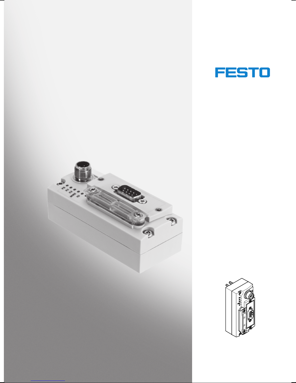
Universal bus node
CTEU-DN
Description,
functions and
maintenance
Bus nodes
Type CTEU-DN
DeviceNet fieldbus
protocol
Description
573745
en 1206NH
[756445]
Page 2

Page 3

Contents and general safety instructions
Original de.......................................
Edition en 1206NH.................................
Designation P.BE-CTEU-DN-OP+MAINT-EN..............
Order no. 573745..................................
© (Festo AG & Co. KG, D-73726 Esslingen, 2012)
Internet: http://www .festo.com
E-Mail: [email protected]
Reproduction, distribution or sale of this document or
communication of its contents to others without express
authorization is prohibited. Offenders will be liable for
damages. All rights reserved in the event that a patent,
utility model or design patent is registered.
Festo P.BE-CTE U-DN-OP+MAINT-EN en 1206NH
I
Page 4

Contents and general safety instructions
Allen-Bradley®,CAN®, DeviceNet®,CIP®,IO-Link®, QuickConnect®,Rockwell®,Rockwell
Automation
®
,RSLinx®,RSLogix®,RSNetWorx®und TORX®are registered trademarks of
the respective trademark owners in certain countries.
II
Festo P.BE-CTEU-DN-OP+MAINT-E N en 1206NH
Page 5

Contents and general safety instructions
Contents
Designated use VII........................................................
Range of application and certifications VIII.....................................
Target group VIII..........................................................
Service IX...............................................................
Instructions on this description IX...........................................
Important user instructions X..............................................
1. Introduction 1-1...................................................
1.1 General informatio n on the CTEU product family 1-3......................
1.1.1 Hardware components 1-3...................................
1.1.2 I-port interface 1-4..........................................
1.1.3 CTEU-DN function range on the DeviceNet (brief overview) 1-5......
1.2 General information on the fieldbus protocol DeviceNet 1-6................
1.2.1 Central component of the fieldbus protocol 1-6..................
1.2.2 DeviceNet specifications 1-7..................................
1.2.3 DeviceNet Confo rmance 1-7..................................
2. Installation and interfaces 2-1.......................................
2.1 Installation 2-3....................................................
2.1.1 Safety regulations 2-3.......................................
2.1.2 Mounting the bus node 2-4...................................
2.2 Interfaces 2-6.....................................................
2.2.1 Connection and display components 2-6........................
2.2.2 Power supply 2-7...........................................
2.2.3 Power supply connection 2-8.................................
2.2.4 Functional test - no network connection 2-8.....................
2.2.5 Fieldbus connection 2-9.....................................
2.2.6 Basic settings for fieldbus communication 2-12...................
Festo P.BE-CTE U-DN-OP+MAINT-EN en 1206NH
III
Page 6

Contents and general safety instructions
2.3 Device replacement 2-17.............................................
2.3.1 Replacing the bus node 2-17..................................
2.3.2 Replacing the I-port device – identical device type 2-18.............
2.3.3 Replacing the I-port device – different device type (change) 2-19.....
2.3.4 Replacing the CAPC electrical connection box 2-20.................
3. Preparing for commissioning 3-1.....................................
3.1 Preparing to commissioning a PLC 3-3.................................
3.1.1 General instructions 3-3.....................................
3.1.2 Prerequisites for commissioning 3-4...........................
3.2 Switching on 3-5...................................................
3.2.1 Switching on the power supply 3-5............................
3.2.2 Normal operati ng status
(fieldbus communication functional test) 3-6....................
3.2.3 DeviceNet participant features (EDS file) 3-10.....................
3.2.4 Downloading and installing an EDS file 3-11......................
3.2.5 Entering participant properties manually 3-12....................
4. Commissioning 4-1................................................
4.1 Commissioning on the DeviceNet - Overview 4-3.........................
4.2 Network configuration and bus node parameterisation 4-5................
4.2.1 Insert the participant in the project/network 4-5.................
4.2.2 Assign the participant to a scanner 4-6.........................
4.2.3 Set the I/O parameters of the participant (Standard EDS) 4-7.......
4.2.4 Assign the I/O addresses of the participant (Standard EDS) 4-9.....
4.2.5 Loading the configuration into the scanner. 4-10...................
4.3 Parameterisation 4-11...............................................
4.3.1 Methods of parameterisation 4-11..............................
4.3.2 Parameterisation with RSNetWorx (with standard EDS) 4-12.........
4.3.3 Device-specific parametrisation 4-15............................
4.3.4 Behaviour of the inputs and outputs in fail state mode 4-15.........
4.3.5 Behaviour of the inputs and outputs in idle state mode 4-16.........
4.3.6 Parameterisation via a user program (explicit messaging) 4-16.......
4.4 Checklist for commissioning 4-19......................................
IV
Festo P.BE-CTEU-DN-OP+MAINT-E N en 1206NH
Page 7

Contents and general safety instructions
5. Diagnostics 5-1...................................................
5.1 Summary of diagnosti cs options 5-3...................................
5.2 Diagnostics via LED display 5-4.......................................
5.2.1 Normal operati ng status display 5-4...........................
5.2.2 PS-LED status display 5-5....................................
5.2.3 Status display X1-/X2-LEDs 5-6...............................
5.2.4 Status display MNS-LED 5-8..................................
5.2.5 I/O-LED status display 5-9....................................
5.3 Reaction to malfunctions in the control system 5-10.......................
5.4 Diagnostics via network/fieldbus 5-11..................................
5.4.1 Diagnostics via configuration software 5-11......................
5.4.2 Short circuit/overload 5-13....................................
6. Error handling 6-1.................................................
6.1 Fault finding and error elimination 6-3.................................
6.1.1 Check installation 6-3.......................................
6.1.2 Check the power supply 6-4..................................
6.1.3 Restart communication between the bus node and the device 6-5...
6.1.4 Check fieldbus communication 6-5.............................
6.1.5 Check DeviceNet configuration 6-6.............................
6.1.6 Read out diagnostic messages via DeviceNet 6-7.................
Festo P.BE-CTE U-DN-OP+MAINT-EN en 1206NH
V
Page 8

Contents and general safety instructions
A. Technical appendix A-1.............................................
A.1 Technical data A-3..................................................
A.1.1 General properties A-3......................................
A.1.2 Power supply A-6...........................................
A.1.3 Signal transmission A-7......................................
A.2 Terms and abbreviations A-8.........................................
A.3 F ai l state behaviour A-11.............................................
A.4 DeviceNet object model A-13..........................................
A.4.1 DeviceNet Object model for CTEU-DN – overview A-13..............
A.4.2 Participant features (Identity object) A-16........................
A.4.3 DeviceNet object A-17........................................
A.4.4 Assembly Object A-18........................................
A.4.5 Discrete output byte object A-19...............................
A.4.6 Discrete input byte object A-20.................................
A.4.7 Festo diagnostic object (I-port status byte) A-21...................
A.4.8 Festo module object A-23.....................................
A.4.9 Festo system object A-24......................................
A.4.10 Festo parameter object A-25...................................
B. Index B-1.........................................................
VI
Festo P.BE-CTEU-DN-OP+MAINT-E N en 1206NH
Page 9

Contents and general safety instructions
Designated use
The bus node type CTEU-DN documented in this description
manual has been designed exclusively for use as a participant (slave-device) on the DeviceNet fieldbus.
Thebusnodemayonlybeusedasfollows:
– As intended in industrial environments;
outside of industrial environments, e.g. in commercial and
mixed-residential areas, actions to suppress interference
may have to be taken.
– in original status without unauthorised modifications;
only the conversions or modifications described in the
documentation supplied with the product are permitted.
– in perfect technical condition
The limit values specified for pressures, temperatures, electrical data, torques etc. must be observed.
Comply with the legal rules and regulations and standards,
rules of the testing organisations and insurance companies
and national specifications applicable for the location.
Warning
• Use only PELV circuits for the electrical power supply in
accordance with IEC/EN 60204-1
(Protective Extra-Low Vo l tage, PELV).
• Observe also the general requirements for PELV circuits
in accordance with IEC/EN 60204-1.
• Useonlyvoltagesourcesthatensureareliableelectric
separation of operating voltage in accordance with
IEC/EN 60204-1.
• Always connect both circuits for operating and load
voltage supply.
Festo P.BE-CTE U-DN-OP+MAINT-EN en 1206NH
VII
Page 10
Contents and general safety instructions
Through the use of PELV circuits, protection against electric
shock (protection against direct and indirect contact) is ensured in accordance with IEC/EN 60204-1.
Range of application and certifications
The product fulfils the requirements of EU directives and is
marked with the CE marking.
Standards and test values which the product must comply
with and fulfil can be found in the section “Technical appendix”. The product-relevant EU directives can be found in
the declaration of conformity .
Target group
Certificates and declarations of conformity for this product
can be found online at:
www.festo.com
Information on DeviceNet can be found online at:
www.odva.org
The bus node has been certified by the Open Device Vendor
Association (ODVA):
This description is intended exclusively for technicians
trained in control and automation technology, who have
experience in installation, commissioning, programming and
diagnostics of programmable logic controllers (PLC) and
fieldbus systems.
VIII
Festo P.BE-CTEU-DN-OP+MAINT-E N en 1206NH
Page 11

Contents and general safety instructions
Service
Please contact your local Festo service centre if you have any
technical problems.
Instructions on this description
This manual is Part II of the product documentation and
contains specific information about the configuration,
parameterisation, commissioning, programming and
diagnostics of the bus node with the DeviceNet fieldbus
protocol.
Information relating to installing the bus node can be found in
Part I of the product documentation entitled “Universal bus
node CTEU-DN - Installation and Interfaces”, which is supplied with the bus node.
All information on installation and the interfaces can also be
foundinSection2.1ofthisdescription.
Information for mounting the bus node on the CAPC electrical
connection box can be found in the assembly instructions
supplied with the electrical connection box.
Information about other bus nodes and components of the
CTEU… product family can be found in the user documentation for the respective product.
All documents can also be found online at:
www.festo.com Support Portal: Enter search term,
e.g. “CTEU” User documentation
Festo P.BE-CTE U-DN-OP+MAINT-EN en 1206NH
IX
Page 12
Contents and general safety instructions
Important user instructions
Danger categories
This description includes instructions on the possible dangers
which can occur if the product is used incorrectly. These
instructions are marked with a signal word (Warning, Cautio n,
etc.), printed on a shaded background and marked
additionally with a pictogram.
A distinction is made between the following danger warnings:
Warning
... means that failure to observe this instruction may result
in serious personal injury or material damage.
Caution
... means that failure to observe this instruction may result
in personal injury or material damage.
Note
... means that failure to observe this instruction may result
in material damage.
In addition, the following pictogram marks passages in the
text which describe activities with electrostatically sensitive
devices:
X
Electrostatically sensitive devices: Incorrect handling may
cause damage to devices.
Festo P.BE-CTEU-DN-OP+MAINT-E N en 1206NH
Page 13
Contents and general safety instructions
Marking special information
The following pictograms mark passages in the text which
contain special information.
Pictograms
Information:
Recommendatio ns, tips and references to other information
sources.
Accessories:
Specifications on necessary or useful accessories for the
Festo product.
Environment:
Information on the environmentally friendly use of Festo
products.
Text designations
• Bullet points denote activities that may be carried out in
any sequence.
1. Numerals denote activities that must be carried out in the
sequence specified.
– Arrowheads indicate general lists.
Festo P.BE-CTE U-DN-OP+MAINT-EN en 1206NH
XI
Page 14
Contents and general safety instructions
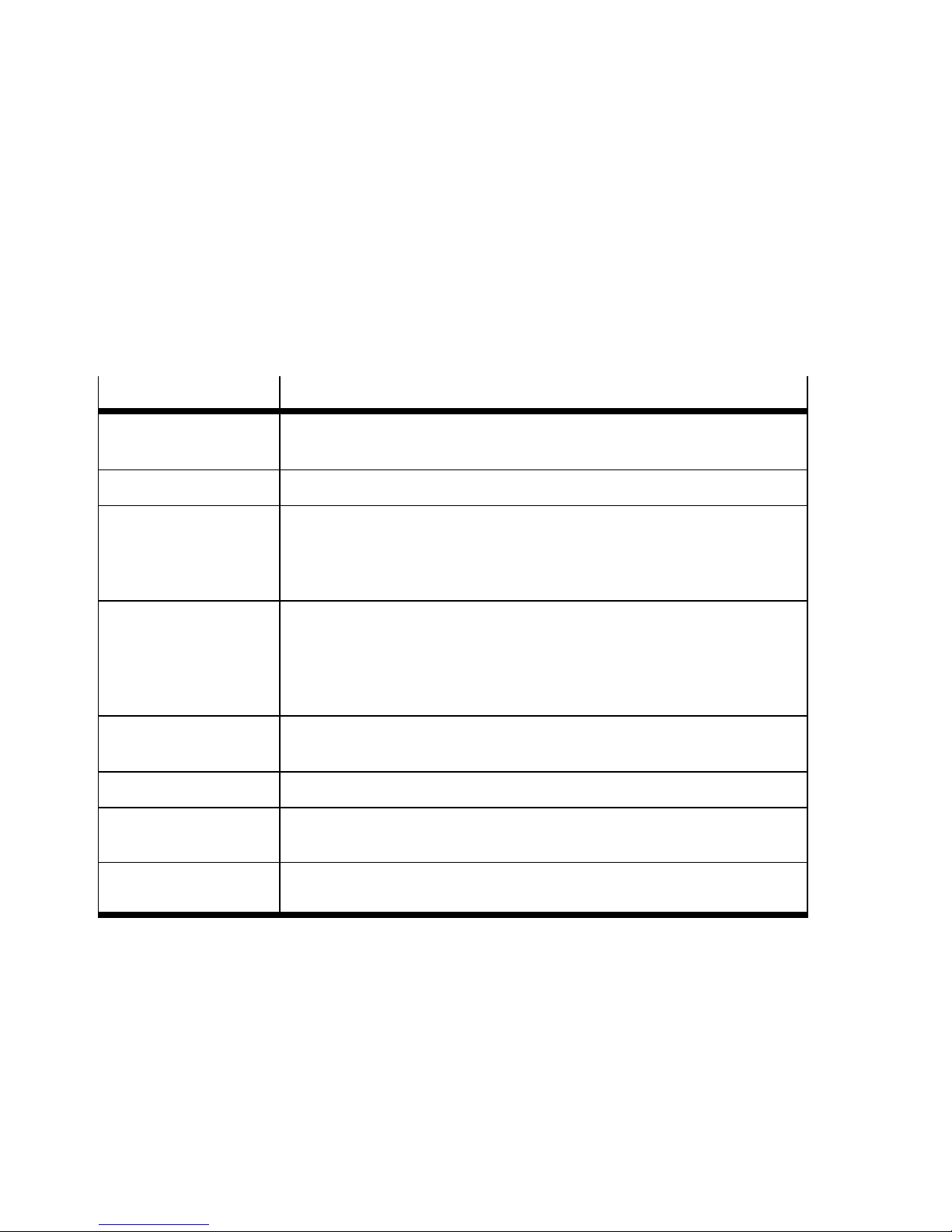
The table below contains all the essential product and network-specific terms and abbreviations that are used in this
description.
An overview of all terms and abbreviations can be found
in the Appendix A.2.
Abbreviation/term
EDS Electronic Data Sheets contain product-specific data, e.g. the bus node
EDS library Manages the characteristics of the various fieldbus/network participants
Fail state Bus node function, also referred to as “fail safe” function; defines the
I-port I-port is a Festo-specific interface for transmitting communication data
Object Directory Makes all important fieldbus/network participant parameters accessible
ODVA Open Device Vendor Association, DeviceNet umbrella organisation
PLC Programmable logic controller, also referred to as system controller or
Significance
characteristics see also “DCF” Appendix A.2
state assumed by outputs or valves following network or c ommunication
errors, activates for example a reset of the outputs - or alternatively holds
the last state
(process data, sensor signals, pilot signals) and supply voltages. The
I-port communication protocol is based on the IO link protocol. The electrical and mechanical link between bus nodes and I-port device is standardised.
in a standardised manner
controller for short
RSNetWorx Configuration, parameterisation, commissioning and diagnostics software
for DeviceNet from Rockwell Automation/Allen-Bradley
Tab. 0/1: System-specific terms and abbreviations (extract)
XII
Festo P.BE-CTEU-DN-OP+MAINT-E N en 1206NH
Page 15

Introduction
Chapter 1
Introduction
1-1Festo P.BE-CTE U-DN-OP+MAINT-EN en 1206NH
Page 16

1. Introduction
Contents
1. Introduction 1-1...................................................
1.1 General informatio n on the CTEU product family 1-3......................
1.1.1 Hardware components 1-3...................................
1.1.2 I-port interface 1-4..........................................
1.1.3 CTEU-DN function range on the DeviceNet (brief overview) 1-5......
1.2 General information on the fieldbus protocol DeviceNet 1-6................
1.2.1 Central component of the fieldbus protocol 1-6..................
1.2.2 DeviceNet specifications 1-7..................................
1.2.3 DeviceNet Confo rmance 1-7..................................
1-2
Festo P.BE-CTEU-DN-OP+MAINT-E N en 1206NH
Page 17
1. Introduction
1.1 General information on the CTEU product family
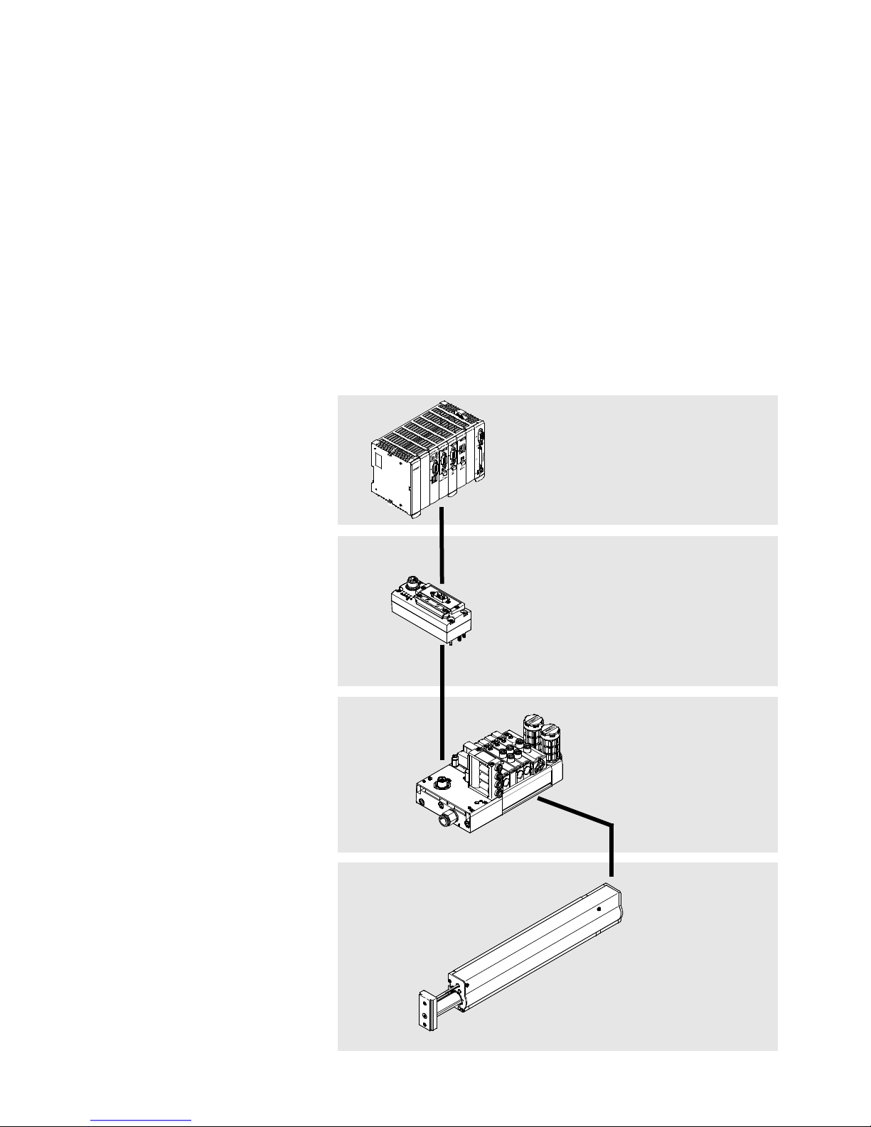
The CTEU… product family enables the creation of a decentralised automation system in a DeviceNet fieldbus system
(network).
1.1.1 Hardware components
1 Higher-order con-
troller (Host system/Master/PLC/
IPC)
2 Fieldbus level:
bus node
CTEU-DN
3 Device level:
e.g. valve
terminal VTUB-12
4 Drive level:
e.g. Linear
module HME
1
2
3
Festo P.BE-CTE U-DN-OP+MAINT-EN en 1206NH
4
1-3
Page 18

1. Introduction
1.1.2 I-port interface
I-port is a Festo-specific interface for transmitting communication data (process data, sensor signals, pilot signals) and
supply voltages.
The I-port communication protocol is based on the IO link
protocol. The electrical and mechanical link between bus
nodes and I-port device is standardised.
The bus node has separate operating and load voltage supplies. It also supplies voltage to the devices connected via the
I-port interface.
Located at the bottom of the bus node is the I-port interface
for connection to an I-port-compatible device, e.g. valve terminal or decentralised electrical connectio n box.
1-4
Festo P.BE-CTEU-DN-OP+MAINT-E N en 1206NH
Page 19

1. Introduction
1.1.3 CTEU-DN function range on the DeviceNet (brief ove rview)
– Object-based fieldbus system
– Master-Slave system architecture
– Process synchronisation in accordance with the Producer/
Consumer method
– Connection-based communication procedure: point-to-
point connection (peer-to-peer messaging), where appli cable as Multicast connection and/or Master/slave I/O
connection
– Predefined master/slave connection set for the simplified
transmission of I/O data between the master and the PLC
and the slave and the bus node
– Real-time operation: Exchange of I/O data in “real-time”
– Message types supported for the Master/slave I/O con-
nection:
– Polled communication (“I/O polling”)
– Change of state / Cyclic communication
– Supports the QuickConnect feature and the Automatic
Device Replacement (ADR) function: guarantees faster
reconnection between DeviceNet-Scanner and bus nodes,
e.g. after replacing the bus nodes
– Application-specific process data transmission based on
the Common Industrial Protocol (CIP):
– Time-critical I/O data via “I/O messages”
(I/O messaging or implicit messaging)
Festo P.BE-CTE U-DN-OP+MAINT-EN en 1206NH
– Data required for configuration, diagnostics and
management via explicit messaging
– Module- specific parameterisation via manufacturer-spe-
cific objects
1-5
Page 20

1. Introduction
1.2 General information on the fieldbus protocol DeviceNet
1.2.1 Central component of the fieldbus protocol
Participant features
A DeviceNet participant is configured based on product-specific data and characteristics, which the manufacturer
provides in the form of electronic datasheets (EDS). These
EDS files contain the product code, revision data and the
available address space (input/output size).
The configuration program of the DeviceNet Master manages
the EDS files of all fieldbus participants in a list or an EDS
library.
Special Device Configuration Files contain additional project
data over and above the content and scope of the EDS file.
Communication protocol
According to the layer model of the International Organisation
for Standardisation (Open Systems Interconnection Reference
Model - OSI), DeviceNet uses the principles of the Controller
Area Network (CAN) Protocol at security layer level (Data Link
Layer),aswellastheCommonIndustrialProtocol(CIP)forthe
upper communication level.
The DeviceNet protocol therefore represents a conversion
from CIP based on CAN principles.
1-6
Festo P.BE-CTEU-DN-OP+MAINT-E N en 1206NH
Page 21
1. Introduction
Message types
The following message types are available for master/slave
networks (predefined master/slave connection set):
– Polled communication (“I/O polling”)
or
– Change of state / Cyclic communication
Object directories
DeviceNet devices have an object directory which makes all
important participant parameters accessible in a standardized manner. A DeviceNet system is essentially configured by
accessing the objects in the object directory of the individual
fieldbus participants.
1.2.2 DeviceNet specifications
Further Information on DeviceNet can be found in the
Internet:
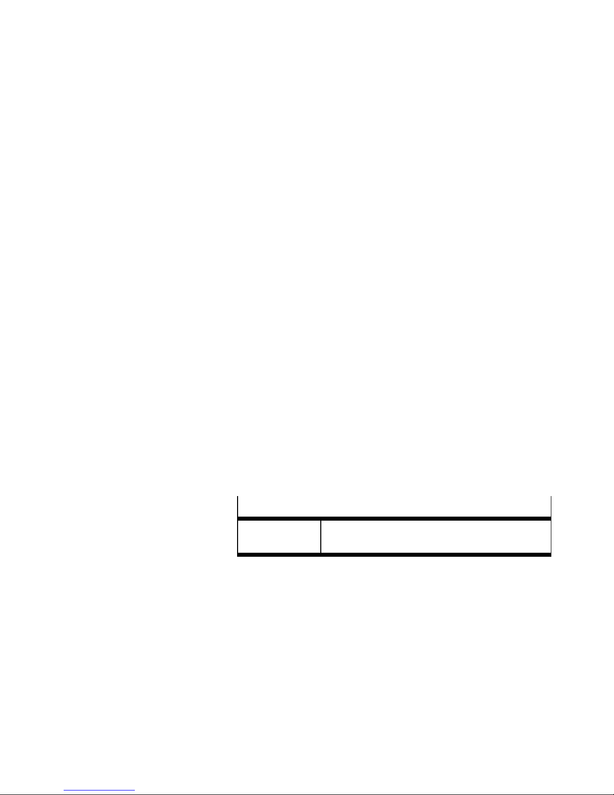
DeviceNet specifica tions
ODVA Open Device Vendor Association
Tab. 1/1: DeviceNet specifications
1.2.3 DeviceNet Conformance
The CTEU-DN bus node conforms to the specifications of the
Open Device Vendor Association (ODVA).
http://www.odva.org
Festo P.BE-CTE U-DN-OP+MAINT-EN en 1206NH
1-7
Page 22

1. Introduction
1-8
Festo P.BE-CTEU-DN-OP+MAINT-E N en 1206NH
Page 23

Installation and interfaces
Chapter 2
Installation and interfaces
2-1Festo P.BE-CTE U-DN-OP+MAINT-EN en 1206NH
Page 24

2. Install ati on and interfaces
Contents
2. Install a tion and interfaces 2-1.......................................
2.1 Installation 2-3....................................................
2.1.1 Safety regulations 2-3.......................................
2.1.2 Mounting the bus node 2-4...................................
2.2 Interfaces 2-6.....................................................
2.2.1 Connection and display components 2-6........................
2.2.2 Power supply 2-7...........................................
2.2.3 Power supply connection 2-8.................................
2.2.4 Functional test - no network connection 2-8.....................
2.2.5 Fieldbus connection 2-9.....................................
2.2.6 Basic settings for fieldbus communication 2-12...................
2.3 Device replacement 2-17.............................................
2.3.1 Replacing the bus node 2-17..................................
2.3.2 Replacing the I-port device – identical device type 2-18.............
2.3.3 Replacing the I-port device – different device type (change) 2-19.....
2.3.4 Replacing the CAPC electrical connection box 2-20.................
2-2
Festo P.BE-CTEU-DN-OP+MAINT-E N en 1206NH
Page 25

2. Install ati on and interfaces
2.1 Installation
This chapter contains information for mounting the Bus node
CTEU on an I-port-compatible device (e.g. valve terminal with
I-port interface) and for installing this combination in a higher-level field bus system (network).
2.1.1 Safety regulations
Warning
Danger of injury through uncontrolled movements of connected equipment.
Make sure that electrical and pneumatic equipment are in
a de-energised and pressureless status.
Before working on the pneumatics:
• Switch off the compressed air supply
• Vent the valve terminal
Before working on the electrical components, e.g. before
installation or maintenance work:
• Switch off power supply
In this way, you can avoid:
– uncontrolled movements of loose tubing
– accidental and uncontrolled movements of the connec-
ted actuators
– undefined switching states of the electronics
Festo P.BE-CTE U-DN-OP+MAINT-EN en 1206NH
2-3
Page 26
2. Install ati on and interfaces
Note
The bus node includes electrostatically sensitive devices.
• Do not touch any electrical or electronic components.
• Observe the handling specifications for electrostatically
sensitive devices.
They will help you avoid damage to the electronics.
Note
Use protective caps to seal unused connections. This is
how you achieve protection class IP65/IP67.
2.1.2 Mounting the bus node
A valve terminal with I-port interface or an electrical connection box, type CAPC-..., is required to mount the bus node.
Note
Information on mounting the bus node on the electrical
connection box type CAPC-... canbefoundintheassembly
instructions that accompany the connection box.
For H-rail mounting, you also need the mounting kit
CAFM-... (CAPC and CAFM).
2-4
1. Inspect the seals and sealing surfaces on bus node and
valve terminal.
Festo P.BE-CTEU-DN-OP+MAINT-E N en 1206NH
Page 27

2. Install ati on and interfaces
2. Plug the bus node onto the valve terminal in the right
position and without tilting.
3. First, lightly screw in the three self-tapping screws with a
TORX screwdriver (size T10): use existing threads, if applicable.
4. Tighten the screws with 1.0 Nm.
Festo P.BE-CTE U-DN-OP+MAINT-EN en 1206NH
2-5
Page 28
2. Install ati on and interfaces
2.2 Interfaces
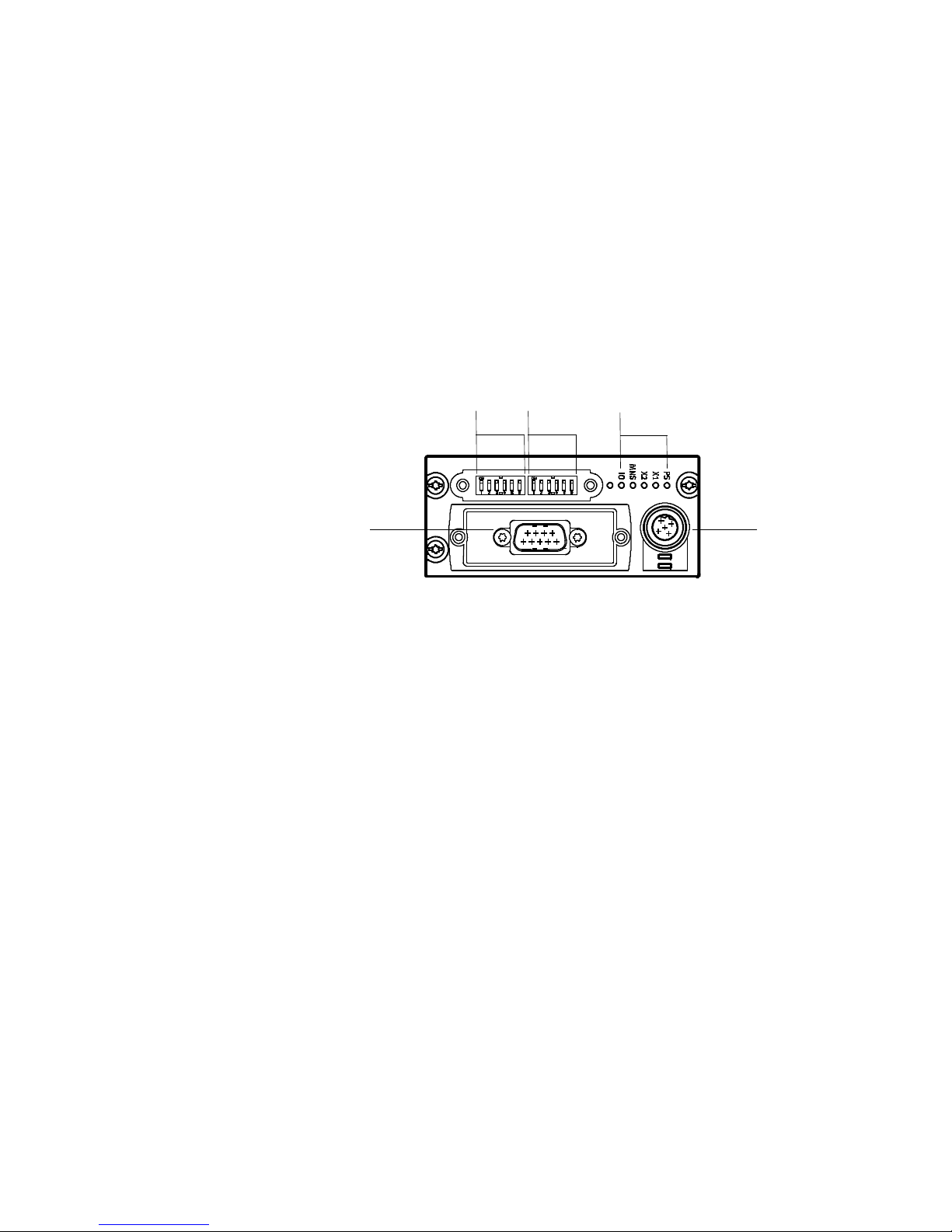
2.2.1 Connection and display components
The following electrical connection and display components
can be found on the bus node:
12
5
3
1 DILswitchgroup1( Section 2.2.6)
2 DILswitchgroup2( Section 2.2.6)
3 Status LEDs:
bus status LEDs, CTEU-specific LEDs;
status indicator and diagnostics ( Section 3.2.2)
4 Power supply connection
for bus node and any connected equipment,
e.g. valve terminal ( Section 2.2.2);
M12, 5-pin, B-coded, pin plug connector
X0
4
2-6
5 Field bus connection (field bus interface):
sub-D, 9-pin, pin plug connector, DE-9
( Section 2.2.3)
On the bottom of the bus node is the I-port interface for connection to an I-port-compatible device, e.g. valve terminal or
decentralised electrical connection box.
Festo P.BE-CTEU-DN-OP+MAINT-E N en 1206NH
Page 29

2. Install ati on and interfaces
2.2.2 Power supply
The bus node has separate operating and load voltage
supplies. The bus node also supplies voltage to equipment
connected via the I-port interface.
Note
• Use only PELV circuits for the electrical power supply in
accordance with IEC/EN 60204-1
(Protective Extra-Low Vo l tage, PELV).
• Observe the general requirements in accordance with
IEC/EN 60204-1 for PELV circuits.
• Useonlyvoltagesourcesthatguaranteeareliableelec-
tric separation of operating and load voltage in accordance with IEC/EN 60204-1.
• Always connect both circuits for operating and load
voltage supply.
Through the use of PELV circuits, protection against electric
shock (protection against direct and indirect contact) is ensured in accordance with IEC/EN 60204-1.
Note
Fieldbus participants of different manufacturers have different tolerances regarding the power supply to the bus
(V+, also designated as CAN_V+ or CAN+).
– Tolerance range of the power supply to the bus of the
fieldbus interface CTEUDN: DC 11 … 30 V, reverse polarity protected
Festo P.BE-CTE U-DN-OP+MAINT-EN en 1206NH
Observe this fact when placing the power supply unit and
designing the fieldbus length.
2-7
Page 30
2. Install ati on and interfaces
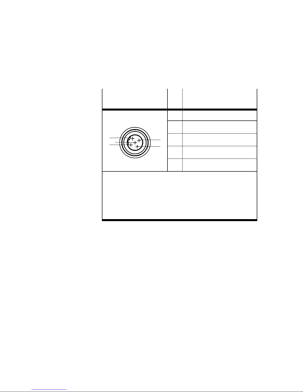
2.2.3 Power supply connection
Power supply connec-
Pin Assignment
1)
tion (M12, B-coded)
1 24 V
2 24 V
1
5
2
1)
V
V
FE: Earth terminal (functional earth)
2)
The connection to functional earth must be ensured via the
connected device or electrical connectionbox C APC-...
: Operating voltage for electronics/sensors
EL/SEN
(Power System, PS)
OUT/VAL
: Load voltage for outputs/valves
(Power Load, PL)
4
3
3 0V
4 0V
5 FU
EL/SEN
VAL/OUT
EL/SEN
OUT/VAL
2)
Tab. 2/2: Power supply connection
(PS)
(PL)
(PS)
(PL)
2.2.4 Functional test - no network connection
2-8
For the connection to power supply units or the power supply,
use cables with M12 coupling (socket plug connector),
B-coded, in accordance with IEC 61076-2
Accessories www.festo.com/catalogue.
Check the operating status of the bus node using the status
LEDs PS and X1 and/or X2:
–TheLEDPS is illuminated green when the power supply is
present at both circuits.
–TheLEDsX1 and/or X2 illuminate green when an I-port
device is connecte d.
Festo P.BE-CTEU-DN-OP+MAINT-E N en 1206NH
Page 31
2. Installation and interfaces
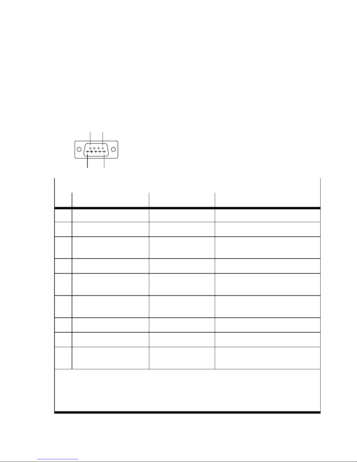
2.2.5 Fieldbus connection
Fieldbus interface - connection technology and pin
allocation
9 6
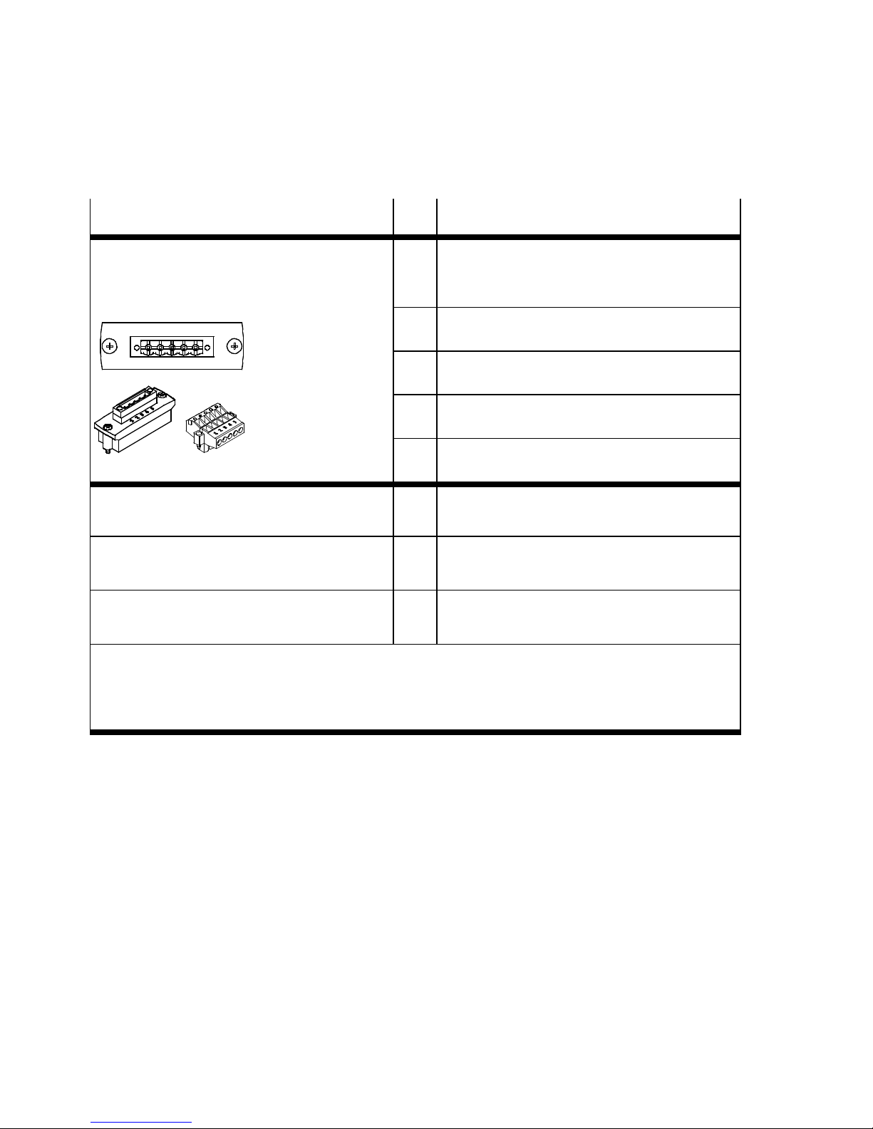
There is a 9-pin sub-D pin plug connector (DE-9) on the bus
node for connection to the fieldbus.
5
1
Fieldbus connection (fieldbus interface; sub-D, DE-9)
Pin Allocation (bus signal) Typical wire colour Signal description
1 n.c. n.a. not connected
2 CAN_L Blue DeviceNet Bus Low (CAN Bus Low)
3 V–
(“CAN_GND”)
4 n.c. n.a. not connected
5 Drain
(“CAN_SHLD”)
6 GND n.a. Ground,
Black Power supply to bus (0 V),
2)
3)
4)
Screening,
housing
connected to Pin 6
Screening (shield),
functional earth (FE)
connected to Pin 3
1)
7 CAN_H White DeviceNet Bus High (CAN Bus High)
8 n.c. n.a. not connected
9 V+
(“CAN_V+”)
1)
Received/transmitted data
2)
The bus power supply is not used by the bus node, but is required for the correct functioning of
the DeviceNet bus system
3)
Also connect screening to the plug connector housing
4)
Optional; the ground connection is not used
Tab. 2/3: Fieldbus connection (fieldbus interface; sub-D, DE-9) – pin allocation
Festo P.BE-CTE U-DN-OP+MAINT-EN en 1206NH
Red Power supply to bus
(DC 24 V)
2)
1)
2-9
Page 32

2. Installation and interfaces
Fieldbus connecting cable – Specification and configuration
For fieldbus communication, Festo recommends the use of a
two-pair, screened fieldbus connecting cable (network cable).
• You need at least a screened 4-wire line
(CAN_H/CAN_L as well as V +/V –).
• Preferably use cable with twisted and screened wire
pairs.
• Always use a terminating resistor (121Ω ±1%, 0.25W)
at both ends of the fieldbus between the wires for
CAN_H and CAN_L.
• Connect the screening of the fieldbus cable to the
fieldbus plug.
• Connect the screening continuously to all fieldbus
cables and earth the screening only once (starshaped) to avoid ground loops.
• Make sure that the connected fieldbus equipment or
the decentrali sed adapter is earthed.
• Observe the specifications in the manuals of your con-
trol system, in particular regarding the bus lines,
cable type, max. length of branch lines and branches
as well as the connection technology (network plug,
adapter).
• In calculating the max. effective data rate, also take
into account the length of branch lines and branches
Section 2.2.6, “Setting the DIL switches”
Information on maximum usable data rate (baud
rate).
2-10
Festo P.BE-CTEU-DN-OP+MAINT-E N en 1206NH
Page 33
2. Installation and interfaces
Note
Faulty installation and high transmission rates may cause
data transmissio n errors as a result of signal reflectio ns
and attenuations.
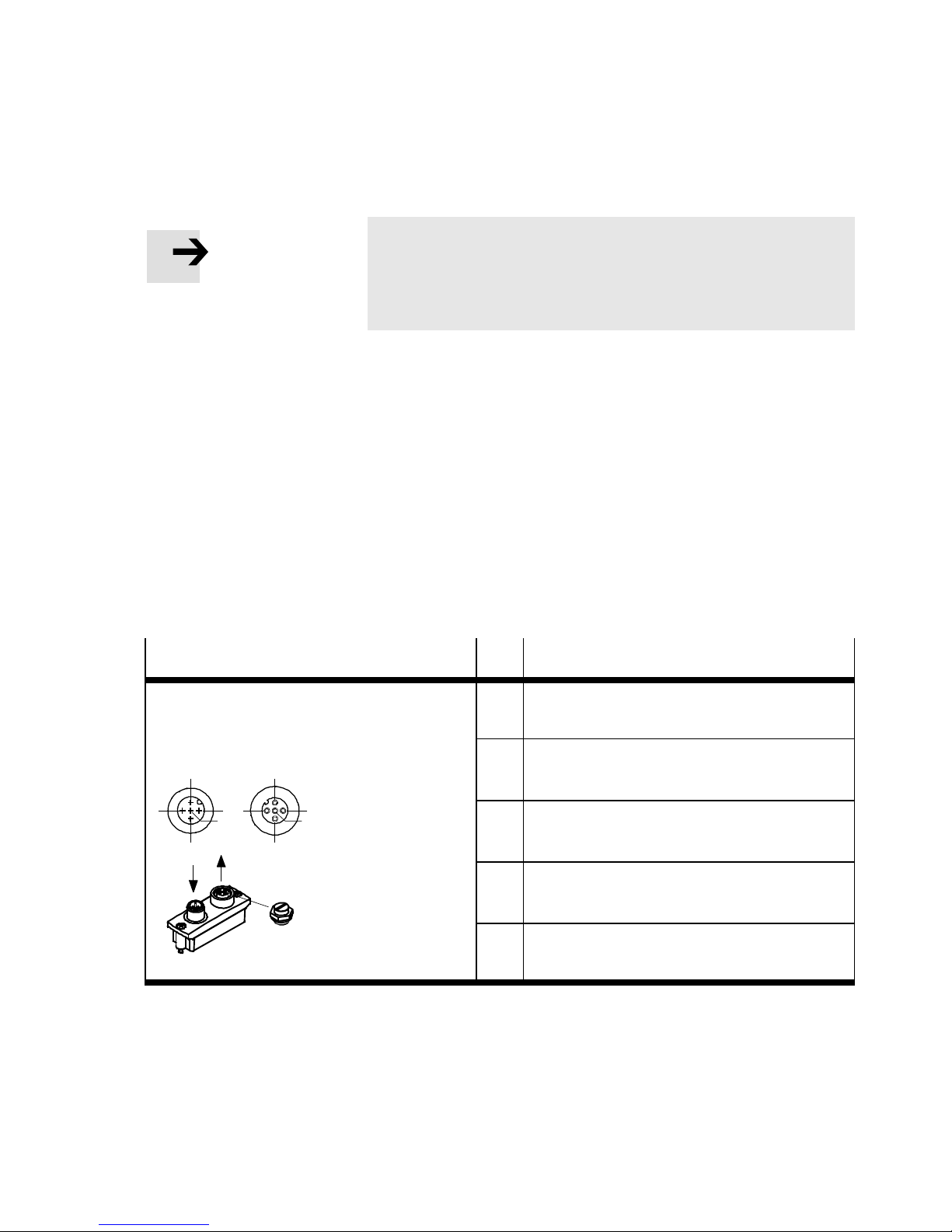
Fieldbus adapter (bus connection/plug-adapter) for
continued fieldbus communication
With fieldbus adapters from Festo ( Tab. 2/4 below), you
can separate the fieldbus connection from the bus node
without interrupting the communication of the remaining
fieldbus participants.
You can use the following fieldbus adapters for forwarding
the fieldbus connection.
Fieldbus adapter
Bus connection
FBA-2-M12-5POL
2
3
Bus IN
1
5
4
1)
2
1
4
Bus OUT
3
5
1)
Pin Allocation
1 Functional earth (FE)
2 Power supply to bus (DC 24 V)
3 Power supply to bus (0 V)
4 CAN_H
5 CAN_L
Tab. 2/4: Fieldbus adapter (bus connection/plug-adapter) - Part 1
Festo P.BE-CTE U-DN-OP+MAINT-EN en 1206NH
2-11
Page 34
2. Installation and interfaces
Fieldbus adapter Pin Allocation
Bus connection
1 Power supply to bus (0 V)
FBA-1-SL-5POL
with FBSD-KL-2X5POL
2)
2 CAN_L
1 2 3 4 5
3 Functional earth (FE)
4 CAN_H
5 Power supply to bus (DC 24 V)
Fieldbus adapter
FBA-CO-SUB-9-M12
3)
Fieldbus adapter
FBS-SU B-9-BU-2x5PIN-B
Fieldbus adapter
Assembly instructions
FBA-CO-SUB-9-M12
Assembly instructions
FBS-SU B-9-BU-2x5PIN-B
www.festo.com Support Portal
FBS-SU B-9-WS-CO-K
1)
Protective cap or plug with bus termination resistor required if connection remains unused
2)
Use cables with a minimum cross-section of 0.34 mm
3)
When using standard sub-D plugs to IP20: Connecting screws with UNC female thread required for
2
mounting (type UNC 4-40/M3x6)
Tab. 2/5: Fieldbus adapter (bus connection/plug-adapter) - Part 2
2.2.6 Basic settings for fieldbus communication
2-12
The following basic settings for fieldbus communication must
be made using the DIL switches on the bus node ( Sections
below):
– DeviceNet address (“Station number”)
– Data rate (baud rate)
Festo P.BE-CTEU-DN-OP+MAINT-E N en 1206NH
Page 35
2. Installation and interfaces
– Diagnostic functionality (transmission of diagnostic in-
formation to the process data or access to diagnostic information exclusively via Explicit Messaging)
– Fail state and idle state mode
T o set the DIL switches, you must remove the co ver:
Removal of the DIL switch cover
Proceed as follows:
1. Switch off the power supply.
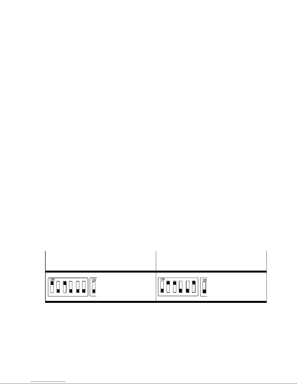
Example 1:
Station number 05
1234 56
2. Unscrew the two mounting screws of the transparent
cover and remove the cover.
Setting the DIL switches
Proceed as follows:
1. Assign to the bus node a station that has not yet been
allocated see examples below for setting the binarycoded DeviceNet address (“Station Numbers”) per DIL
switch group 1 Tab. 2/6.
Example 2:
Station number 38
1
1234 56
1
Tab. 2/6: Setting example for DeviceNet address (“Station number”, DIL switch
group 1)
Festo P.BE-CTE U-DN-OP+MAINT-EN en 1206NH
2-13
Page 36
2. Installation and interfaces
DIL switch
1)
Function
12345
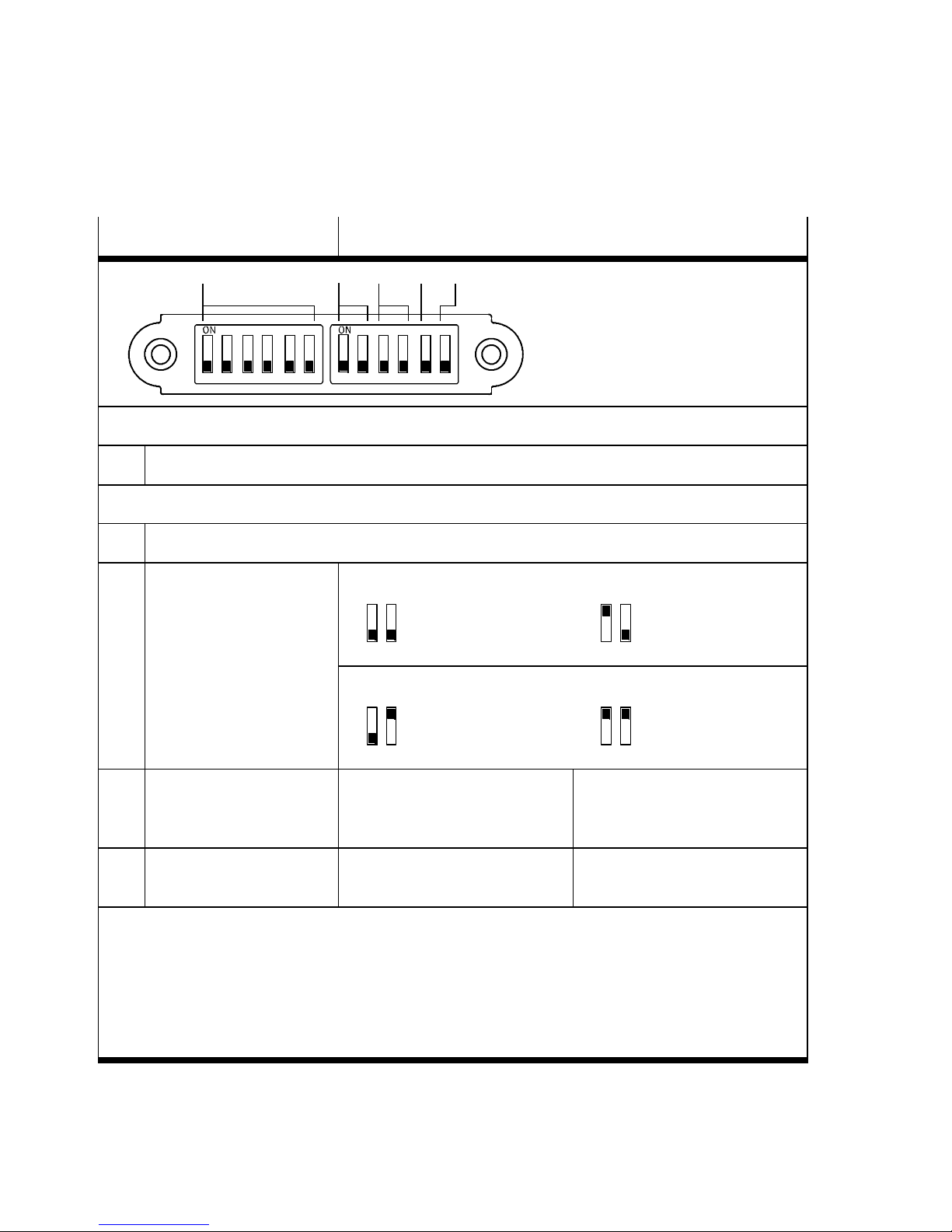
12 34 56 1234 56
DIL switch group 1
1 1 ... 6: DeviceNet address (Station Number), 0 … 63, binary-coded (factory setting: 63)
DIL switch group 2
2 1 ... 2: reserved (OFF)
3 3 ... 4: Data rate/
baud rate
2)
125 kB
DIL 2.3: OFF
DIL 2.4: OFF
2.3 2.4
250 kB
DIL 2.3: ON
DIL 2.4: OFF
2.3 2.4
500 kB
DIL 2.3: OFF
DIL 2.4: ON
2.3 2.4
4 5: Diagnostics mode ON: Diagnostics activated:
Transmission of diagnostic information to the process data
5 6: Fail-state and
idle mode
1)
Switch setting “ON”: (marked on DIL switch accordingly, shown in Fig. at top)
3)
ON: Hold last state OFF: Reset
Reserved
2.3 2.4
OFF: Access to diagnostic information only through explicit
messaging (factory setting)
(factory setting)
Switch setting “OFF”: (shown in Fig. at bottom)
2)
Factory setting: 125 kBaud
3)
Thesettingforthefailstatemodeandtheidlemodeapplyforallinputsandoutputs
– Fail state: no fieldbus c onnection (connection aborted)
– Idle state: PLC is in stop mode
Note Fail state mode is also referred to as “Fail safe mode”
Tab. 2/7: Setting the DIL switch (DIL switch group 1 and 2)
DIL 2.3: ON
DIL 2.4: ON
2-14
Festo P.BE-CTEU-DN-OP+MAINT-E N en 1206NH
Page 37
2. Installation and interfaces
2. Set the baud rate: when setting the baud rate, take into
account the length of the network lines (main bus line,
branch lines and branches) seenotebelow.
Note
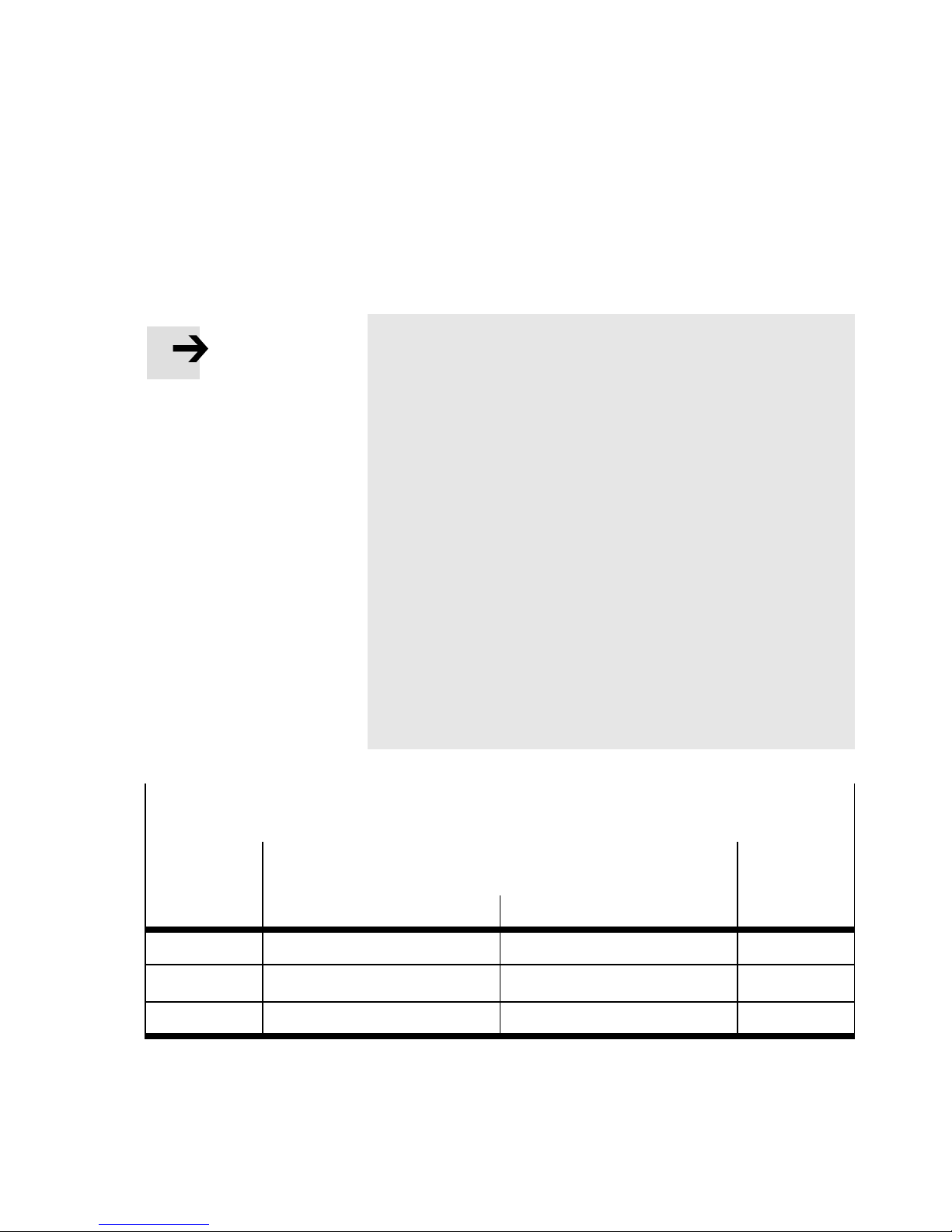
Maximum effective data rate (baud rate)
The setting of the baud rate depends on the length of all
fieldbus connecting cables (network lines).
• Consider the length of the fieldbus line between the PLC
and bus node (main bus line) as well as the length of any
existing branch lines and branches for continued fieldbus configuration.
• Also consider the overall length (sum) of all branch lines.
• The table below contains reference values for the max-
imum baud rate, depending on the line lengths. The
baud rates named here are not supported by all controllers.
• Observe any deviating specifications in the manual of
your control system or network scanner.
• Further information can be found in the specifications of
the ODVA www .odva.org.
Max. data rate (baud rate)
dependent on the line length (reference values)
Main bus
line
(Trunk lin e)
Max. 100 m Max. 6 m Max. 39 m 500 kBaud
Branch line
(Drop line)
Individual branch line All branch lines (total)
Baud rate
Max. 250 m Max. 6 m Max. 78 m 250 kBaud
Max. 500 m Max. 6 m Max. 156 m 125 kBaud
Tab. 2/8: Maximum data rate (baud rate)
Festo P.BE-CTE U-DN-OP+MAINT-EN en 1206NH
2-15
Page 38
2. Installation and interfaces
3. Set the diagnostics and fail-state mode.
Mounting of the DIL switch co v er
1. Place the cover carefully on the bus node. Make sure that
the seal is seated correctly.
2. Tighten the two mounting screws at first hand-tight and
then with a max. torque of 0.4 Nm.
Functional test after making the DIL switch setting with network connection
Check the operating status of the bus node:
1. Connect the bus node to the fieldbus.
2. Check the network co nnection to the PLC using the status
LEDs MNS and IO Tab. 2/9 below
(additional information can be found in Section 3.2.2).
Function
check
With network
connection
LED MNS Flashes green Illuminates green Illuminates green OK
LED IO Is off Flashes green Illuminates green OK
Bus node and
network connection
not configured
Bus node and
network connection
configured
PLC
in Stop mode
PLC
in Run mode
Status
Operating
status of bus
node (test
result)
Tab. 2/9: Functional test using the status LEDs MNS and IO - after making the DIL
switch setting
2-16
Festo P.BE-CTEU-DN-OP+MAINT-E N en 1206NH
Page 39

2. Installation and interfaces
2.3 Device replacement
To avoid connection and start-up errors, observe the following instructions for replacing the bus node, the electrical connection box CAPC... and the connected I-port device.
2.3.1 Replacing the bus node
The configuration and parameterisatio n of the bus node and
theI-portdevicearenot automatically restored when the bus
node is replaced, e.g. for a service event. Observe the following instructio n.
1. Check before replacement whether the PLC or the higherorder system has saved the settings and the settings have
been downloaded.
2. If not, verify which settings are required before replacement, and restore th ese settings after replacement.
3. Switch off the power supply to the bus node.
4. Dismounting / mounting the bus node Section 2.1.
5. Connect all devices prior to switching on the CTEU bus
node, otherwise there will be no process data ( see also
Section 3.1.2 regarding the requirements for start-up).
6. Switch the power supply to the bus node back on.
7. Download the settings or restore the required settings.
Festo P.BE-CTE U-DN-OP+MAINT-EN en 1206NH
2-17
Page 40

2. Installation and interfaces
2.3.2 Replacing the I-port device – identical device type
Observe the following instructions to make sure that the configuration and parameterisation of the I-port device are retained in case of a replacement, e.g. service event.
1. Do not switch off the power supply to the bus node. This
ensures that the parameters for the I-port device saved in
the bus node are retained.
Do not isolate the connecting cables. The configuration of
connected devices is lost as soon as the operating voltage
supply of the bus node is interrupted.
2. Remove the bus node from the I-port device
(Dismantling/Installation Section 2.1).
3. Replace the I-port device.
T o mount/dismount the I-port device, observe the
corresponding product documentation www.festo.com
Support Portal: Enter search term, e.g. “I-port” or
“IO-Link” User documentation.
4. Mount the bus node to the I-port device (Mounting/Dismounting Section 2.1).
The bus node detects the connected I-port device and
transfers the saved configuration and parameterisation to
the I-port device. Transmission of process data starts
automatically .
2-18
Festo P.BE-CTEU-DN-OP+MAINT-E N en 1206NH
Page 41

2. Installation and interfaces
2.3.3 Replacing the I-port device – different device type (change)
The parameterisation of an I-port device is not automatically
restoredifthedevicetypeischanged.
If the I-port device is connected to the bus node via the electrical connection box, there are three distinctly different applications:
– One I-port device is connected to the electrical
connection box:
In this case, switch off the voltage supply to the bus node
and change the I-port device.
T o mount/dismount the I-port device, observe the
corresponding product documentation www.festo.com
Support Portal: Enter search term, e.g. “I-port” or
“IO-Link” User documentation.
Then switch the voltage supply back on and carry out the
required configuratio n and parameterisati o n procedures.
– Two I-port devices are connected to the electrical connec-
tion box, both devices are replaced:
In this case, switch off the voltage supply to the bus node
and change both I-port devices - as described in the previous application.
– Two I-port devices are connected to the electrical connec-
tion box, only one device is changed:
Do not switch off the voltage supply to the bus node. This
ensures that the configuration and parameterisation for
the I-port devices stored in the bus node are retained.
Observe the following instruction.
Festo P.BE-CTE U-DN-OP+MAINT-EN en 1206NH
2-19
Page 42

2. Installation and interfaces
If two I-port devices are connected to the bus node via the
CAPC-... electrical connection box, but only one device is
changed, the following instruction must be observed:
1. Do not switch off the power supply to the bus node. This
ensures that the parameters for the I-port device saved in
the bus node are retained.
Do not isolate the connecting cables. The configuration of
connected devices is lost as soon as the operating voltage
supply of the bus node is interrupted.
2. Replace the I-port device to be changed.
T o mount/dismount the I-port device, observe the
corresponding product documentation www.festo.com
Support Portal: Enter search term, e.g. “I-port” or
“IO-Link” User documentation.
The bus node detects the connected I-port device and
records the corresponding configuration data.
3. Carry out the required configuration and parameterisation
procedures.
2.3.4 Replacing the CAPC-... electrical connection box
Observe the following instructions to make sure that the
parameterisation of the I-port device is retained in case the
electrical connection box is replaced, e.g. service event.
1. Do not switch off the power supply to the bus node. This
ensures that the parameters for the I-port device saved in
the bus node are retained.
2-20
Do not isolate the connecting cables of the bus node. The
configurationofconnecteddevicesislostassoonasthe
operating voltage supply of the bus node is interrupted.
Festo P.BE-CTEU-DN-OP+MAINT-E N en 1206NH
Page 43

2. Installation and interfaces
2. Remove the bus node from the electrical connection box:
Dismantling/Installation Section 2.1.
3. Replace the electrical connection box.
To mount/dismount the electrical connection box,
observe the corresponding product documentation
(assembly instructions) CAPC-F1-E-M12-D2
www.festo.com Support Portal: Enter search term,
e.g. “CAPC-F1-E-M12-D2” User documentatio n.
4. Install the bus node on electrical connection box.
The bus node detects the connected I-port device and
transfers the saved configuration and parameterisation to
the I-port device. Transmission of process data starts
automatically .
Festo P.BE-CTE U-DN-OP+MAINT-EN en 1206NH
2-21
Page 44

2. Installation and interfaces
2-22
Festo P.BE-CTEU-DN-OP+MAINT-E N en 1206NH
Page 45

Preparing for commissioning
Chapter 3
Preparing for commissioning
3-1Festo P.BE-CTE U-DN-OP+MAINT-EN en 1206NH
Page 46

3. Preparing for commissi o ning
Contents
3. Preparing for commissioning 3-1.....................................
3.1 Preparing to commissioning a PLC 3-3.................................
3.1.1 General instructions 3-3.....................................
3.1.2 Prerequisites for commissioning 3-4...........................
3.2 Switching on 3-5...................................................
3.2.1 Switching on the power supply 3-5............................
3.2.2 Normal operati ng status
(fieldbus communication functional test) 3-6....................
3.2.3 DeviceNet participant features (EDS file) 3-10.....................
3.2.4 Downloading and installing an EDS file 3-11......................
3.2.5 Entering participant properties manually 3-12....................
3-2
Festo P.BE-CTEU-DN-OP+MAINT-E N en 1206NH
Page 47
3. Preparing for commissi o ning
3.1 Preparing to commissioning a PLC
The following sections contain fundamental instructions on
commissioning the bus node on the DeviceNet.
Detailed instructions and further information can be found in
the documentation or online help for the controller or control
program.
3.1.1 General instructions
Note
– Bus node CTEU-DN can be used on all DeviceNet control-
lers.
– This chapter describes the configuration and
commissioning procedure using the example of
Rockwell/Allen-Bradley controllers (PLC) via the
RSNetWorx and RSLogix software platfo rm.
– Higher-order controller (PLC) is also called DeviceNet
Master or Host System.
– The DeviceNet fieldbus system is referred to below as
network.
Festo P.BE-CTE U-DN-OP+MAINT-EN en 1206NH
3-3
Page 48

3. Preparing for commissi o ning
3.1.2 Prerequisites for commissioning
• Installation of the CTEU-DN bus node complete
Note
Information on installing and mounting and the basic
setting for the bus node can be found in the description
“Universal bus node CTEU-DN – Installation and
interfaces” (P.BE-CTEU-DN-INSTALL, Part 1 of the product
documentation on the bus node):
www.festo.com Support Portal
Anwenderdokumentation (Techn. Dokumentation).
• Make sure that the DIL switches of the bus node are set
correctly.
Basic setting for fieldbus communication checked:
– DeviceNet address or station number
– Baud rate
Optional settings ch ecked:
–Diagnostics
– Fail state and idle mode
• Make sure that all DeviceNet connecting cables are con-
nected and checked:
• Host system (controller) and bus node connected to
the network
• Network connectio ns checked
3-4
Festo P.BE-CTEU-DN-OP+MAINT-E N en 1206NH
Page 49
3. Preparing for commissi o ning
3.2 Switching on
3.2.1 Switching on the power supply
Warning
• Prior to switch on: make sure that the requirements for
commissioning have been met. Also observe Section 3.1.2, especially regarding the DIL switch setting.
• During operation: do not alter the DIL switch setting
during operation. This will prevent accidental and uncontrolled movements of the connected actuators and
undefined switching states of the electronics.
Note
• Please observe the switching-on instructions in the
manual for your controller.
No specific sequence needs to be followed when switching on
separate voltage supplies. You can connect the voltage supply to the individual system components, e.g. the host system
and/or the higher-order controller, as well as the operating
and load voltage supply to the field bus system in any order
you wish.
Festo P.BE-CTE U-DN-OP+MAINT-EN en 1206NH
3-5
Page 50
3. Preparing for commissi o ning
3.2.2 Normal operating status
(fieldbus communication functional test)
After the switch on procedure, the status LEDs indicate the
operating status and correct function of the bus node and the
fieldbus communication.
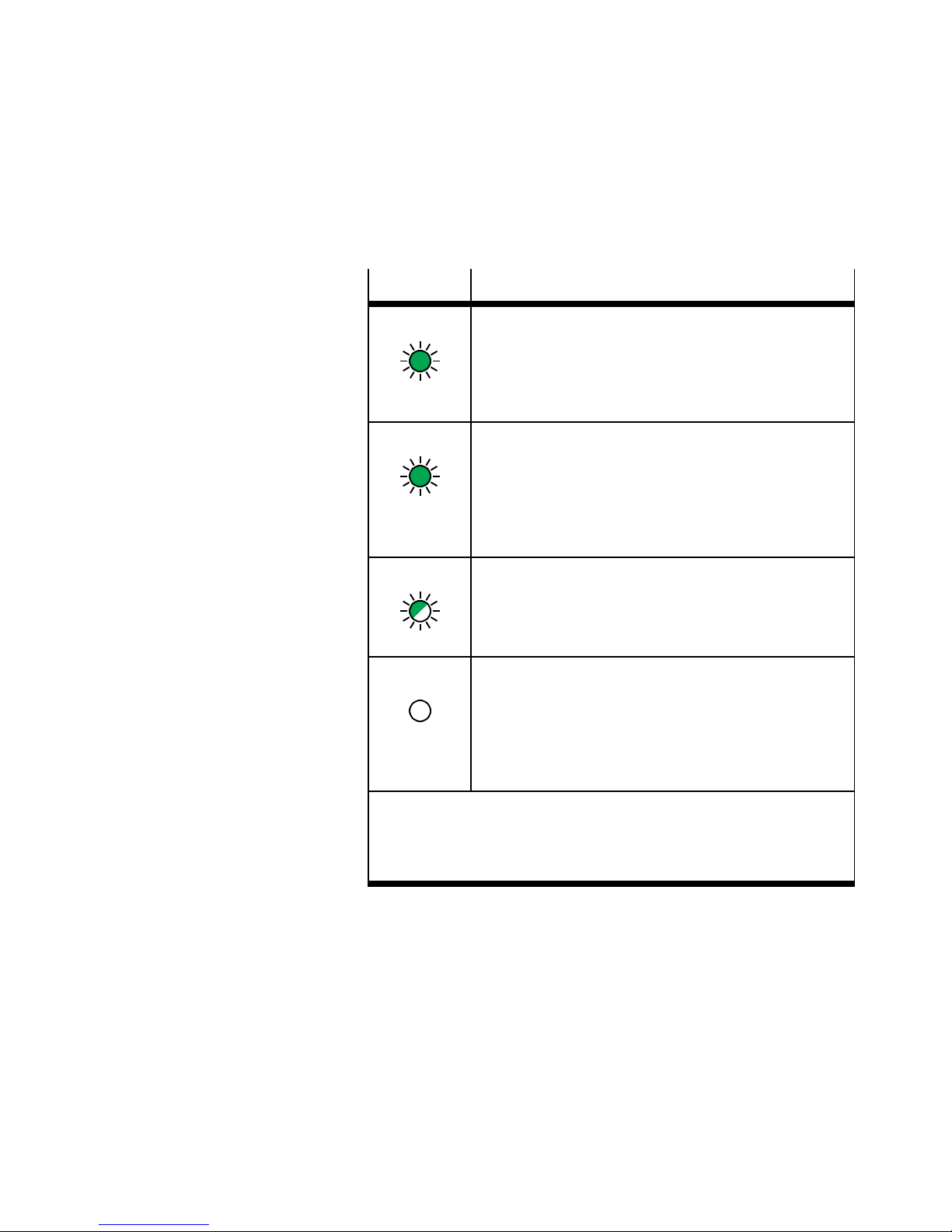
– Tab. 3/10 shows the status of the LEDs without configura-
tion of the bus node
– Tab. 3/11 shows the status of the LEDs with configuration
of the bus node, i.e. following error free commissioning
(PLC is in stop mode)
– Tab. 3/12 shows the status of the LEDs with configuration
of the bus node, i.e. following error free commissioning
and during normal operation (PLC is in run mode)
Note
Information on diagnostics using the LED displays can be
found in section 5.2.
3-6
Festo P.BE-CTEU-DN-OP+MAINT-E N en 1206NH
Page 51
3. Preparing for commissi o ning
LED display Status and significance
PS illuminates green:
– Voltage supply (Power System, PS) is OK
– Operating voltage applied
(in the approved range)
– Load voltage present ( in the approved range)
X1/X2 illuminates green:
– Device is correctly connected to the bus node
– Internal communication between bu s node and
device 1 or device 2 is error free
2)
– Operating and load voltage present (in the ap-
proved range)
1)
1)
MNS flashes green:
– Fieldbus communication present (“online” operat-
ing status), but not configured
(in this case OK because bus node not configured)
IO is off:
– Commissioning of the bus node and fieldbus
connection not complete or not successful
(OK because in this case the bus node is not yet
configured,i.e. the configuration of the bus node
via the PLC has not yet been executed)
1)
Display depends on whether the c onnected device monitors the
load voltage and reports to the bus node
2)
Separate accessory with two interfaces for connection of an additional device required
Tab. 3/10: Status LEDs after switch on – bus node not con-
figured
Festo P.BE-CTE U-DN-OP+MAINT-EN en 1206NH
3-7
Page 52
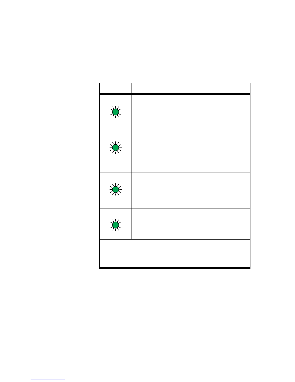
3. Preparing for commissi o ning
LED display Status and significance
PS illuminates green:
– Voltage supply (Power System, PS) is OK
– Operating voltage applied
(in the approved range)
– Load voltage present (in the approved range)
X1/X2 illuminates green:
– Device is correctly connected to the bus node
– Internal communication between bus node and
device 1 or device 2 is error free
2)
– Operating and load voltage present (in the ap-
proved range)
1)
1)
MNS illuminates green:
– Module status/network status (MNS) is error free
(“online” operating status)
– Communication with the fieldbus and with the PLC
is OK
IO flashes green:
– I/O status, connection status is error free
– Communication with the controller (PLC) OK
1)
Display depends on whether the c onnected device monitors the
load voltage and reports to the bus node
2)
Separate accessory with two interfaces for connection of an additional device required
Tab. 3/11: Status LEDs after switch on – bus node con-
figured,PLCinstop mode
3-8
Festo P.BE-CTEU-DN-OP+MAINT-E N en 1206NH
Page 53
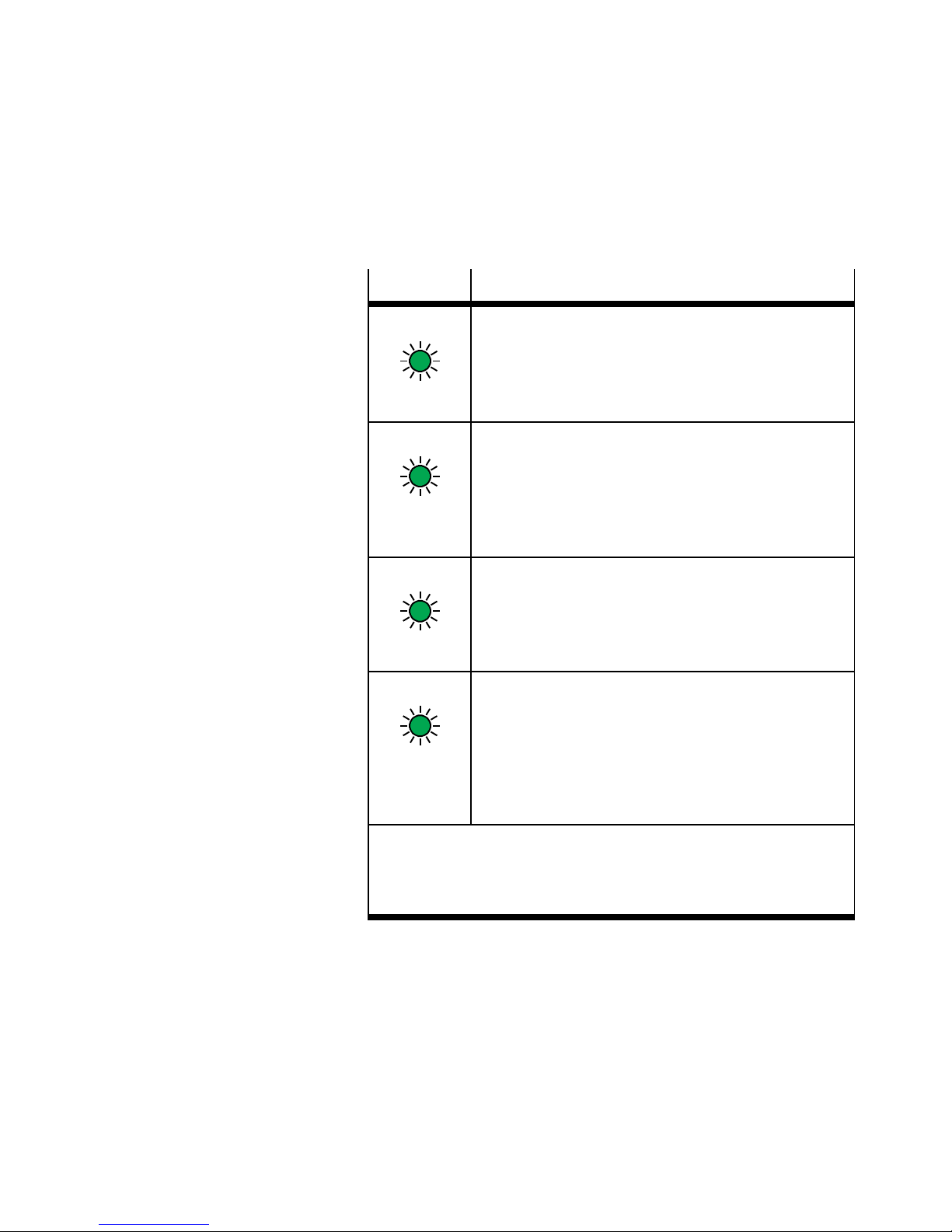
3. Preparing for commissi o ning
LED display Status and significance
PS illuminates green:
– Voltage supply (Power System, PS) is OK
– Operating voltage applied
(in the approved range)
– Load voltage present ( in the approved range)
X1/X2 illuminates green:
– Device is correctly connected to the bus node
– Internal communication between bu s node and
device 1 or device 2 is error free
2)
– Operating and load voltage present (in the ap-
proved range)
1)
1)
MNS illuminates green:
– Module status/network status (MNS) is error free
(“online” operating status)
– Communication with the fieldbus and with the PLC
is OK
IO illuminates green:
– I/O status, connection status is error free
– Communication with the controller (PLC) OK
– IOs are controlled via the fieldbus, as soon com-
missioning of the fieldbus communication is completed successfully and the bus node is controlled
by the PLC
1)
Display depends on whether the c onnected device monitors the
load voltage and reports to the bus node
2)
Separate accessory with two interfaces for connection of an additional device required
Tab. 3/12: Status LEDs after switch on – bus node con-
figured,PLCinrun mode
Festo P.BE-CTE U-DN-OP+MAINT-EN en 1206NH
3-9
Page 54

3. Preparing for commissi o ning
3.2.3 DeviceNet participant features (EDS file)
To configure the CTEU-DN bus node, an Electronic Data Sheet
(EDS) containing all product-specific data and characteristics
of the bus node accessible via the network is available: The
EDS is therefore also referred to as the device description file.
The characteristics and functions described in the EDS file are
summarised under the term DeviceNet participant characteristics.
DeviceNet participant characteristics can also be configured
manually, without installing an EDS file (“enter”).
All characteristics of the DeviceNet participants are usually
contained in an EDS library in the controller software.
EDS variants The individual network participants are configured via a
standard EDS or a modular EDS:
– A standard EDS contains all the required information
across the entire installation system e.g. the bus node
and corresponding valve terminal.
– A modular EDS provides a separate EDS file for every sys-
tem component, every module (bus node, I/O module,
valve terminal etc.) as well as individual functions.
EDS for CTEU- DN To configure the CTEU-DN bus node or the CTEU installation
system, a standard EDS file is available Section 3.2.4.
3-10
Festo P.BE-CTEU-DN-OP+MAINT-E N en 1206NH
Page 55
3. Preparing for commissi o ning
3.2.4 Downloading and installing an ED S file
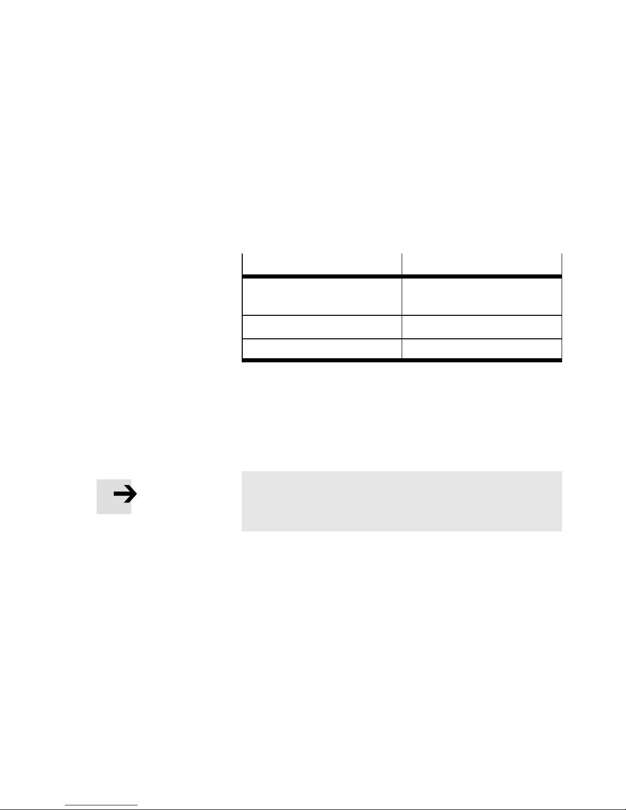
ThecurrentEDSfilecanbefoundontheFestowebsite
www.festo.com Support Portal Enter search term:
“CTEU-DN” Firmware and driver: “DeviceNet EDS file for
CTEU-DN”.
File type
EDS download file
(archive file)
EDS file Cteu-dn.eds
Icon file CTEU-DN.ico
File name
Festo_CTEU-DN_EDS_…zip
Tab. 3/13: Configuration files (Standard EDS) for CTEU-DN
EDS file Install the EDS file using the configuration software of the
higher-order controller (PLC). Please refer to the manuals or
theOnlineHelpforthePLCsoftwareforprocedures.
Note
The old EDS file is overwritten when a new EDS file is
loaded (installed).
Icon files Depending on the configuration program used, you can as-
sign an icon to the bus node. This icon appears at the configuration program user interface and represents the bus node
or the CTEU installation system.
Festo P.BE-CTE U-DN-OP+MAINT-EN en 1206NH
Most configuration programs install the icon automatically.
Manual installation is not usually required.
3-11
Page 56
3. Preparing for commissi o ning
3.2.5 Entering participant properties manually
When an EDS file is installed, the following information about
the DeviceNet participant is added to the EDS library. This
information can also be entered manually.
Information
Vendor name Festo AG & Co. KG
Vendor ID 26d/ (0x1A)
Device type 12d/ (0xC)
Product code 6000d/ (0x1770)
Major revision / Minor revision 1/1
Input size / output size Dependent on the connected I-por t device
Product name CTEU-DN
Description
Tab. 3/14: Participant characteristics of the CTEU-DN bus node
When the EDS library has been extended, the valve terminal
is entered in the participant list as a possible DeviceNet
participant. It can now be added to the DeviceNet network
Section 4.1 and 4.2.
3-12
Festo P.BE-CTEU-DN-OP+MAINT-E N en 1206NH
Page 57

Commissioning
Chapter 4
Commissioning
4-1Festo P.BE-CTEU-DN-OP+MAINT-EN en 1206NH
Page 58

4. Commissioning
Contents
4. Commissioning 4-1................................................
4.1 Commissioning on the DeviceNet - Overview 4-3.........................
4.2 Network configuration and bus node parameterisation 4-5................
4.2.1 Insert the participant in the project/network 4-5.................
4.2.2 Assign the participant to a scanner 4-6.........................
4.2.3 Set the I/O parameters of the participant (Standard EDS) 4-7.......
4.2.4 Assign the I/O addresses of the participant (Standard EDS) 4-9.....
4.2.5 Loading the configuration into the scanner. 4-10...................
4.3 Parameterisation 4-11...............................................
4.3.1 Methods of parameterisation 4-11..............................
4.3.2 Parameterisation with RSNetWorx (with standard EDS) 4-12.........
4.3.3 Device-specific parametrisation 4-15............................
4.3.4 Behaviour of the inputs and outputs in fail state mode 4-15.........
4.3.5 Behaviour of the inputs and outputs in idle state mode 4-16.........
4.3.6 Parameterisation via a user program (explicit messaging) 4-16.......
4.4 Checklist for commissioning 4-19......................................
4-2
Festo P.BE-CTEU-DN-OP+MAINT-E N en 1206NH
Page 59

4. Commissioning
4.1 Commissioning on the DeviceNet - Overview
When the participant characteristics have been configured
(e.g. by installation of the EDS file), the following steps are
required for starting up the bus node:
1. Insert the CTEU-DN bus node (“par ticipant”) into the project/network (online or offline).
If the participant is inserted offline, for example, it will be
selected from the participant list and added to the network.
2. Assign the participant to a scanner.
– A network may contain several scanners.
– The participant must be uniquely assigned to a scan-
ner.
3. Define the I/O parameters of the participant.
The following details are required here:
• Number of the I/O bytes to be transmitted
For the CTEU-DN bus node or the CTEU installation
system, the number depends on the connected I-port
devices.
• Message type
For the CTEU-DN bus ode:
– Polled communication (“I/O polling”)
or
– Change of state / Cyclic communication
Festo P.BE-CTE U-DN-OP+MAINT-EN en 1206NH
4-3
Page 60
4. Commissioning
Note
The following applies when using a Allen-Bradley SLC 500
PLC in conjunction with an Allen-Bradley scanner type
1747-SDN:
– “Change of state / Cyclic communication” can only be
used in conjunction with the diagnostics via Strobed I/O
starting from software version V4.015 of the scanner.
• Assign the I/O addresses of the participant to the PLC
operands.
• Diagnosticbytes(forI-port1andI-port2)tothePLC
operands, insofar as diagnostic mode has been activated via the DIL switch.
Note
The specification of diagnostic mode (assignment of diagnostic bytes) must correspond to the DIL switch setting
Section 2.2.6.
4. Load the configuration into the scanner.
4-4
Festo P.BE-CTEU-DN-OP+MAINT-E N en 1206NH
Page 61
4. Commissioning
4.2 Network configuration and bus node parameterisation
Note
This section describes the startup procedure with an AllenBradley-Scanner 1756-DNB (Revision 4.005) and Rockwell
RSNetWorx-Software for DeviceNet, Version 10.00.00
(CPR 9 SR 2).
The fundamental aspects of this description also apply for
other control systems.
4.2.1 Insert the participant in the project/network
1. Install the EDS file: Use the EDS Wizard in RSNetWorx,
which guides you through the installation process.
– Download: Section 3.2.4
– Installation: RSNetWorx EDS Wizard
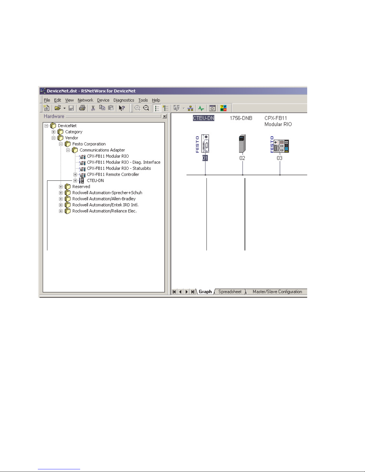
Once the EDS file has been installed, the CTEU-DN participant will appear in the hardware directory of the user
interface (“hardware ” list) 1 in Fig. 4/1.
2. Drag the CTEU-DN participant with the mouse into the
network display on the right-hand side of the user interface 2 in Fig. 4/1.
Festo P.BE-CTE U-DN-OP+MAINT-EN en 1206NH
4-5
Page 62
4. Commissioning
1 2 3
Fig. 4/1: Hardware list and network display in RSNetWorx for DeviceNet
4.2.2 Assign the participant to a scanner
1. Double cl i ck the network scanner (in this case Automa-
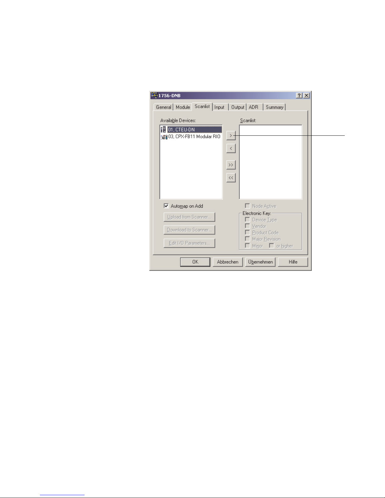
tion/Allen-Bradley 1756-DNB 3 in Fig. 4/1).
The dialogue box for assigning the participant is displayed Fig. 4/2.
2. Select the “Scanlist” tab and assign the available participant to the scanner:
4-6
Festo P.BE-CTEU-DN-OP+MAINT-E N en 1206NH
Page 63
4. Commissioning
1
Button for assigning the participant
1
Fig. 4/2: “Scanlist” tab - assign the network participant to a
scanner (example)
4.2.3 Set the I/O parameters of the participant (Standard EDS)
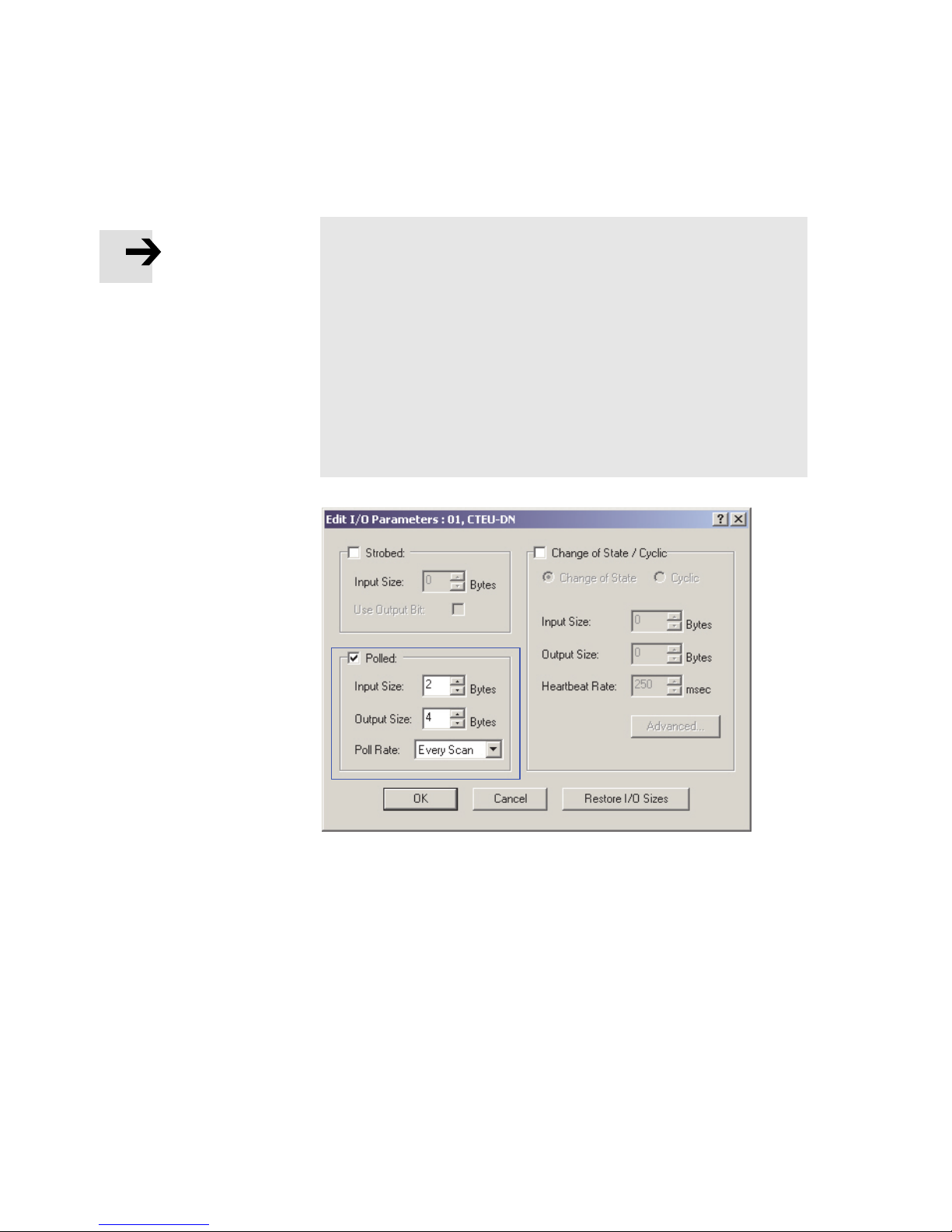
1. Select a participant from the “Scanlist” (Fi g. 4/2). After
double clicking the selection, the dialogue box for setting
the I/O parameters is displayed.
2. Set the I/O parameters of the participant in the “Pol led”
field. Confirm with OK.
Festo P.BE-CTE U-DN-OP+MAINT-EN en 1206NH
4-7
Page 64
4. Commissioning
Note
After displaying the dialogue box, parameter values are
already entered which however do not necessarily have to
match your configuration.
Therefore, always input your own parameter values in the
dialogue box. The corresponding values can be found in
the RX-size or TX-si ze parameters once the current parameter values have been loaded.
Note that I-port 1 and I-port 2 must be parameterised separately .
4-8
Fig. 4/3: Dialogue box for defining the I/O parameters of
the participant
Festo P.BE-CTEU-DN-OP+MAINT-E N en 1206NH
Page 65
4. Commissioning
4.2.4 Assign the I/O addresses of the participant (Standard E DS)
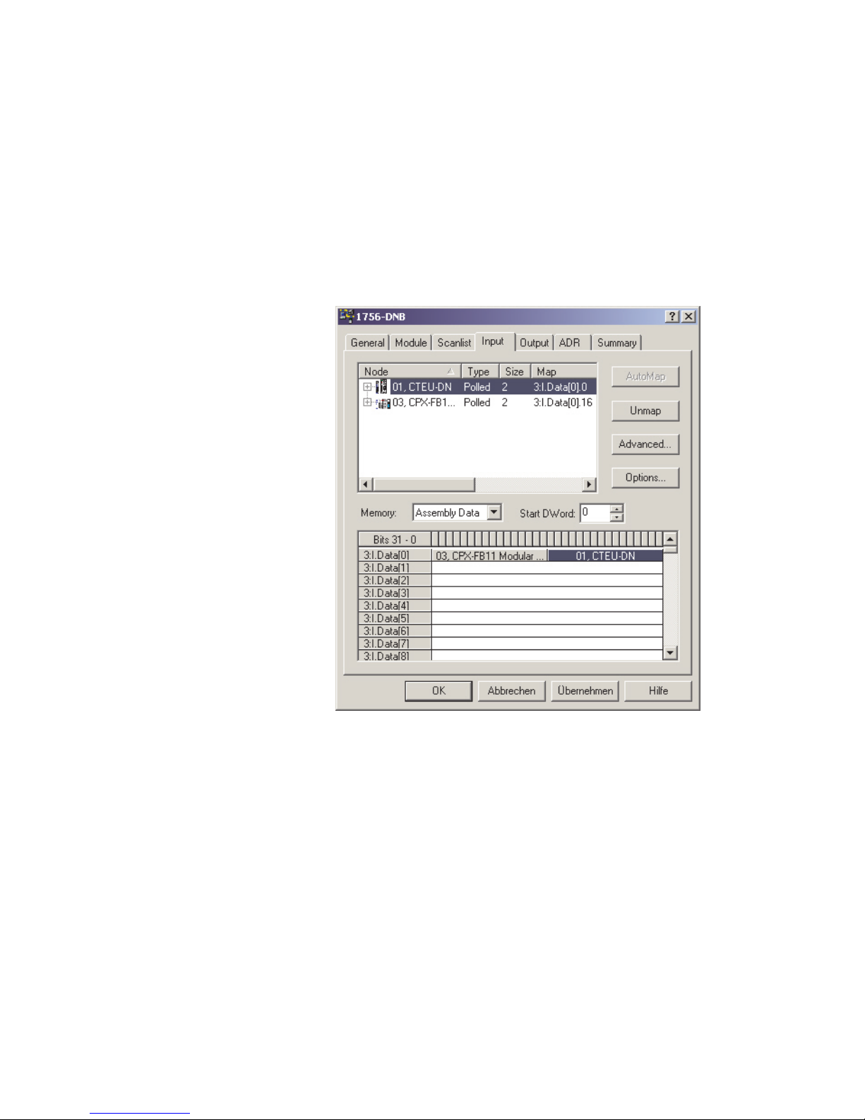
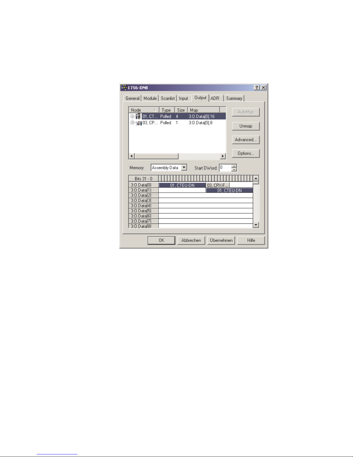
You can assign the I/O addresses of the CPV Direct to the PLC
operands using the “Input” and “Output” tabs.
Festo P.BE-CTE U-DN-OP+MAINT-EN en 1206NH
Fig. 4/4: Address assignment of the input (example)
CTEU-DN appears in the input data with two separate communication connections:
– A “Strobed” connecti o n for transmitting the 8 status bits
(diagnostic information).
– A “Polled” or “Change of State” connection for transmit-
ting the physical input data.
4-9
Page 66
4. Commissioning
Fig. 4/5: Address assignment of the output (example)
4.2.5 Loading the configuration into the scanner.
Finally, load the configuration data into the scanner. Further
information can be found in the documentation for your scanner.
4-10
Festo P.BE-CTEU-DN-OP+MAINT-E N en 1206NH
Page 67
4. Commissioning
4.3 Parameterisation
Note
Observe the subsequent sections to ensure that the parameterisation required for your application is automatically
restored at switch-on, after a restart or after a devi ce replacement.
Check which settings are required, especially before a
device replacement. Make sure that these settings are
retained or restored (e.g. by the higher-order
controller/PLC) Section 2.3.
4.3.1 Methods of p arameterisation
CTEU-DN can be parameterised as follows ( Tab. 4/15):
– via the configuration program
– via the scanner
–viatheuserprogram
Use the QuickConnect and Automatic Device Replacement
(ADR) DeviceNet functions or communi cation and programming via Explicit Messaging, in order to set the required parameters.
In this case, the PLC automatically transmits the programmed
parameters to the bus node after switch-on. The settings will
then be retained even after a restart or device replacement.
Note
The last parameterisation received in the CTEU-DN is always valid.
Festo P.BE-CTE U-DN-OP+MAINT-EN en 1206NH
4-11
Page 68

4. Commissioning
Method Description Benefits Disadvantages
Parameterisation
via the configuration program
(e.g. RSNetWorx)
Parameterisation
via the scanner
(automatic restore
after restart, Configuration Recovery
via QuickConnect
and ADR)
Parameterisation
via the user program (communication and programming via explicit
messaging)
Parameters set via the
configuration program and
direct transmission to the
DeviceNet participant,
local saving in the bus
node CTEU-DN
Parameters set via the configuration program and
transmission to the
scanner:
The parameters are transmitted f rom the scanner to
the DeviceNet participant
after every restart (“Power
On”).
Parameterisation via explicit messaging, parameters
are saved in the PLC
Fast, simple parametrizing during commissioning for testing
the parameters
Parameters are reloaded automatically
after every restart and
are therefore also retained if the device replaced
Parameters are reloaded automatically
after every restart and
are therefore also retained if the device replaced
Parameters (locally saved data) are lost after
arestartordevicereplacement
(For information on device replacement
Section 2.3)
Requirement:
The scanner must support ADR
Requirement:
User program required
Tab. 4/15: Methods of parameterisation
4.3.2 Parameterisation with RSNetWorx (with standard EDS)
4-12
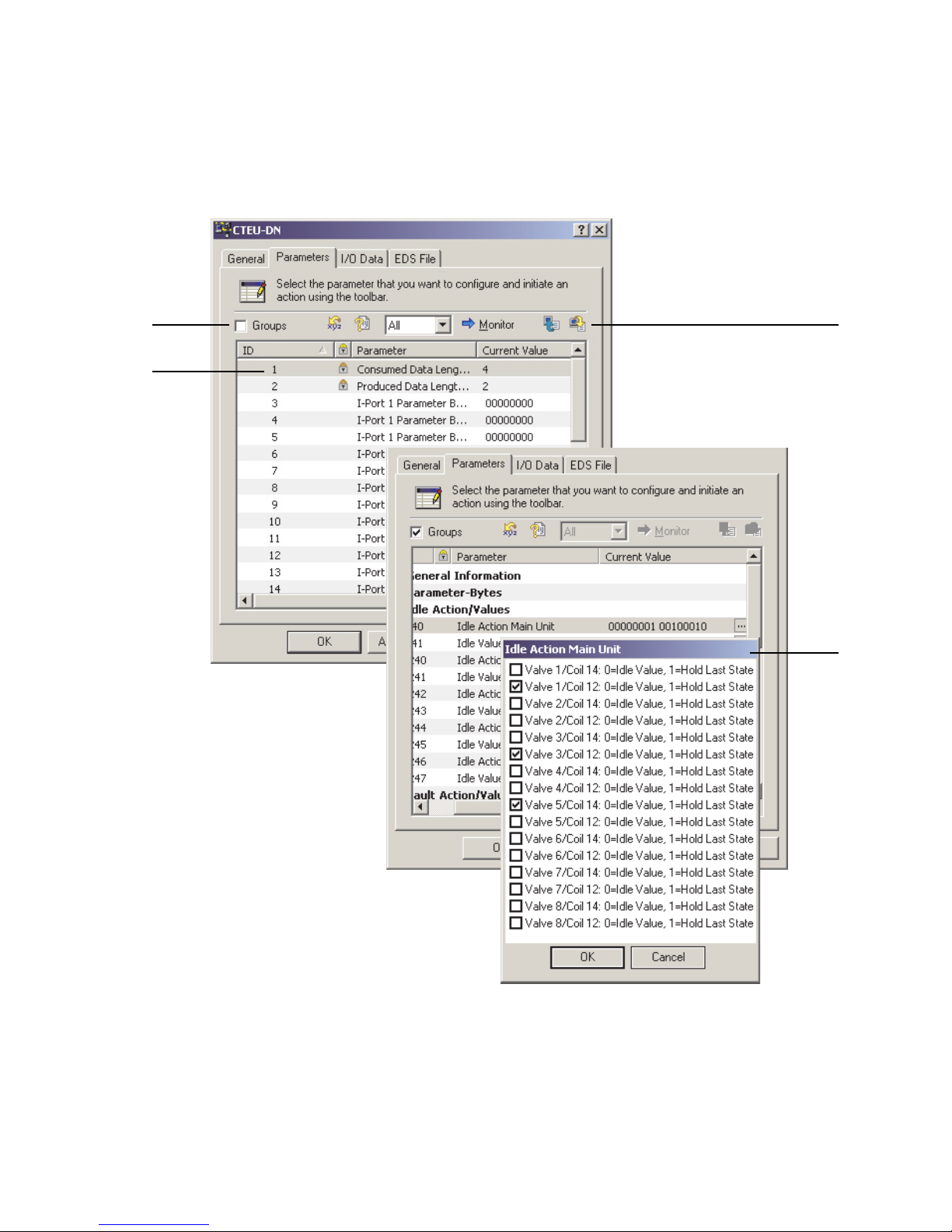
RSNetWorx enables you to parameterise using the
“Parameters” tab of the DeviceNet participant.
This requires the EDS file of the DeviceNet participant to be
contained in the EDS library see Section 3.2.4.
Festo P.BE-CTEU-DN-OP+MAINT-E N en 1206NH
Page 69
4. Commissioning
1
2
4
3
1 “Groups” checkbox for displaying the
parameters and data grouped in
directories
2 List of the parameters and data
Fig. 4/6: Parameterisation examples
Festo P.BE-CTE U-DN-OP+MAINT-EN en 1206NH
3 Window for setting the parameter
values
4 Buttons for online display (monitor
operation), uploading and
downloading parameters
4-13
Page 70

4. Commissioning
Changing parameters Click on a value (Current Value) and change it in the list field
or in a window that opens separately.
The settings saved in the project are displ ayed in offline
mode.
Transmitting parameters In online mode, you can transmit the required parameters
(“upload”) and then display them (“download”).
Please note:
– The displayed parameters are not automatically updated.
– In online mode too, only the settings and parameter val-
ues that are current when called will be displayed.
(It takes a certain amount of time to transmit and display
the values).
– Values that are continuously current are displayed only in
monitor mode, although not with details (no sub-groups
or detailed values).
You can find notes about the specific CTEU-DN parameters in
DeviceNet in section 4.3.3.
4-14
Festo P.BE-CTEU-DN-OP+MAINT-E N en 1206NH
Page 71

4. Commissioning
4.3.3 Device-specific parametrisation
The CTEU-DN bus node has device-specific parameters, referred to as parameter objects, e.g. for setting the behaviour
of the connected I-port devices or for activ ating certain status
signals. These parameters can be set in the configuration
program (“network configurator” “Parameters”).
Thetypeandscopeoftheparameterobjectsavailablein
CTEU-DN depends on the connected I-port device.
Use the QuickConnect and Automatic Device Replacement
(ADR) DeviceNet functions or communi cation and programming via Explicit Messaging, in order to set the required parameters ( Section 4.3.1 and Tab. 4/15).
In this case, the controller (PLC) automatically transmits the
programmed parameters to the bus node after switch-on. The
settings will then be retained even after a restart or device
replacement.
To use explicit messaging programming, you need the object
descriptions and addresses of the DeviceNet object model
Appendix A.4.
4.3.4 Behaviour of the inputs and outputs in fail state mode
In case of a control or communication interference, the network participants, i.e. the bus nodes and the I-port devices,
assume fail state mode.
Possible causes of fail state mode:
– Interference in the control system (PLC/scanner)
– Network/fieldbus interruption (e.g. communication inter-
ference, broken cable)
Festo P.BE-CTE U-DN-OP+MAINT-EN en 1206NH
– Interference to data telegrams.
4-15
Page 72

4. Commissioning
Depending on the DIL switch setting, the inputs and outputs
hold the last state or reset to the basic state Tab. 2/7.
The selected setting applies for all outputs. (Factory setting:
“reset”).
4.3.5 Behaviour of the inputs and outputs in idle state mode
Idle mode is assumed by the network participants when this
is requested by the controller or scanner. The controller is
then in stop mode.
Depending on the DIL switch setting, the outputs hold the last
state or reset to the basic state Tab. 2/7.
The inputs of the network participants continue to be transferred to idle state mode.
The selected setting applies for all inputs and outputs and is
coupled to the setting for the fail state mode. (Factory setting:
“reset”).
4.3.6 Parameterisation via a user program (explicit messaging)
Parameter values can also be read and written by the controller. To do so, communicate and program via “Explicit Message”. The required parameter values are specified in a user
program.
For this parameterisation method, you require device-specifi c
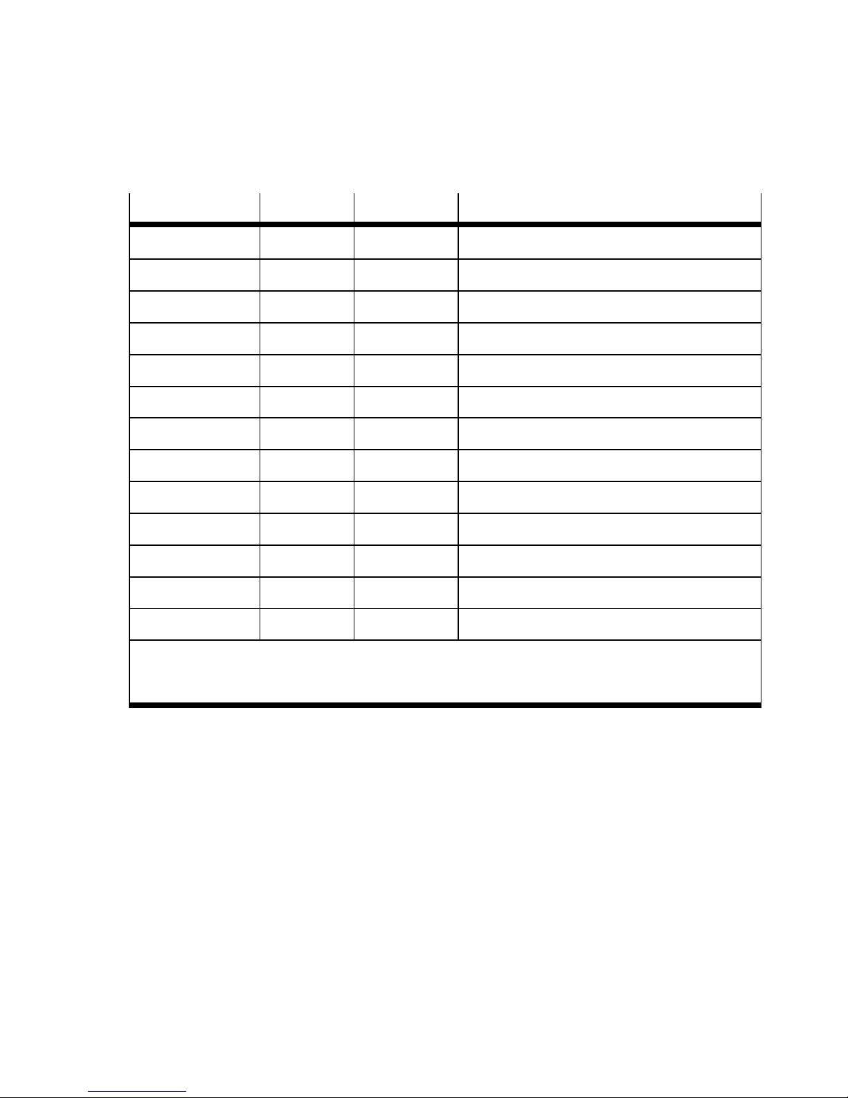
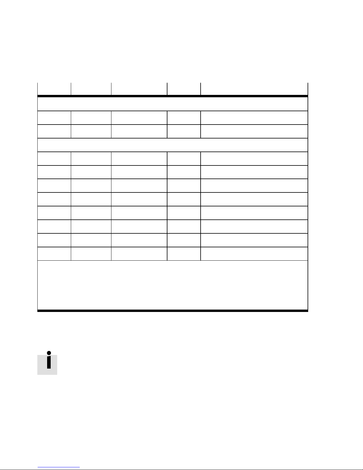
parameter objects and/or the corresponding object descriptions Tab. 4/16 and Tab . 4/17. Note that these tables specify only the frames for using parameterisation via explicit
messaging.
4-16
Detailed object descriptions and addresses of the DeviceNet
object model can be found in Appendix A.4.
Festo P.BE-CTEU-DN-OP+MAINT-E N en 1206NH
Page 73
4. Commissioning
Object class Instance Attribute
1
d
2
d
3
d
4
d
5
d
15
43
100
101
103
104
105
d
d
d
d
d
d
d
1
-
1 - Message router
1 - DeviceNetobjectclass
101, 104 - Assembly object
1 - Connection object class
1...16 - Parameter object c lass
1 - Acknowledge handler class
1...16 - Festo output byte object
1...16 - Festo input byte object
1...2 - Festo diagnostics object
1...2 - Festo module object
1...2 - Festo system object
1)
Name
Identity object
2)
106
d
1)
Informationon“Attribute” Tab. 4/17 or Appendix A.4
2)
System information (device-specific data on the bus node)
3)
This object is device-specific and therefore not contained in the EDS file.
1...2 - Festo parameter object
Tab. 4/16: DeviceNet object model for CTEU-DN
3)
Festo P.BE-CTE U-DN-OP+MAINT-EN en 1206NH
4-17
Page 74
4. Commissioning
Attribute Access Name Type Description
1)
Class attributes
1
Get Revision UINT Revision of the object = 1
2 Get Max instance UINT Max. instance2)of the CIP object = 2
Instance attributes
2)
1 Get/Set Parameter byte 1 BYTE
2 Get/Set Parameter byte 2 BYTE
3 Get/Set Parameter byte 3 BYTE
4 Get/Set Parameter byte 4 BYTE
5 Get/Set Parameter byte 5 BYTE
6 Get/Set Parameter byte 6 BYTE
7 Get/Set Parameter byte 7 BYTE
8 Get/Set Parameter byte 8 BYTE
Note
Write acc ess to these objects and instances is possible only if an I-port-compatible device is connected to the corresponding I-port.
1)
The specific contents (description, “parameters” and “values”) of the objects and instances
depend on th e connecte d I-port device.
2)
Instance 1 refers to the module indentity of Device 1; Instance 2 to module indentity of Device 2.
Tab. 4/17: DeviceNet object relating to CTEU-DN for the device-specific parameterisation
(Festo parameter object) – Class code 106
d
Further information on parameter programming with a user
program (via explicit messaging) can be found in the data on
your controller.
4-18
Festo P.BE-CTEU-DN-OP+MAINT-E N en 1206NH
Page 75

4. Commissioning
4.4 Checklist for commissioning
Observance of the following points helps you to avoid errors
during commissioning on DeviceNet.
• Finally check the DIL switch settings again.
• Check the address assignment of the inputs and outputs.
Check the configured address range (pro cess data and
assigned input and output bytes).
• Test the inputs and outputs if necessary.
• Check the parameterisation, via the configuration pro-
gram for example.
• Make sure that the desired parameterisatio n is restored
after a restart or after fieldbus interruptions.
Festo P.BE-CTE U-DN-OP+MAINT-EN en 1206NH
4-19
Page 76

4. Commissioning
4-20
Festo P.BE-CTEU-DN-OP+MAINT-E N en 1206NH
Page 77

Diagnostics
Chapter 5
Diagnostics
5-1Festo P.BE-CTE U-DN-OP+MAINT-EN en 1206NH
Page 78

5. Diagnostics
Contents
5. Diagnostics 5-1...................................................
5.1 Summary of diagnosti cs options 5-3...................................
5.2 Diagnostics via LED display 5-4.......................................
5.2.1 Normal operati ng status display 5-4...........................
5.2.2 PS-LED status display 5-5....................................
5.2.3 Status display X1-/X2-LEDs 5-6...............................
5.2.4 Status display MNS-LED 5-8..................................
5.2.5 I/O-LED status display 5-9....................................
5.3 Reaction to malfunctions in the control system 5-10.......................
5.4 Diagnostics via network/fieldbus 5-11..................................
5.4.1 Diagnostics via configuration software 5-11......................
5.4.2 Short circuit/overload 5-13....................................
5-2
Festo P.BE-CTEU-DN-OP+MAINT-E N en 1206NH
Page 79
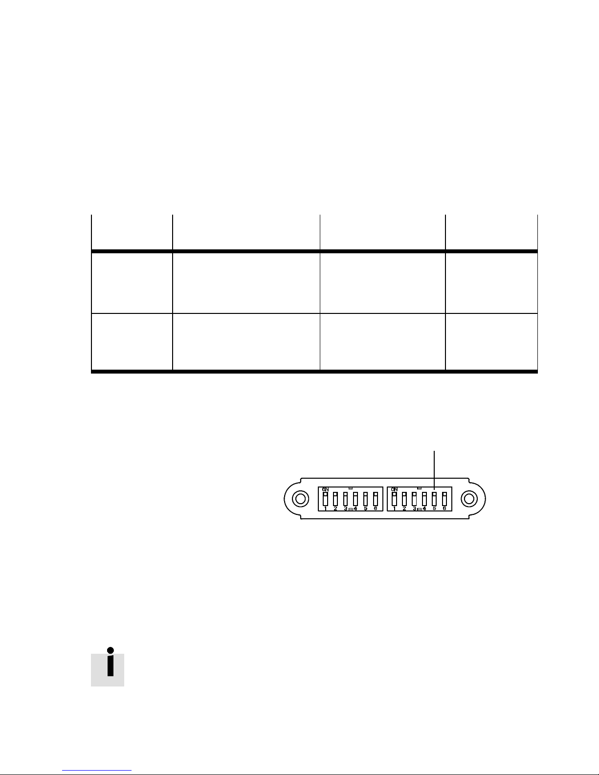
5. Diagnostics
5.1 Summary of diagnostics options
The following options are available for diagnostics and error
elimination, depending on the bus node configuration:
Diagnostic
Brief description Benefits Detailed
possibility
Diagnostics via
LED display
Diagnostics via
fieldbus
BusnodeLEDsindicate
configuration errors, hardware
errors, bus errors, etc.
immediately
Detailed diagnostics via the
DeviceNet network,
transmission of diagnostic
information to the process data
Tab. 5/1: Diagnostics optio ns
1 DIL switch
settings:
–OFF:
Diagnostic
information only
via explicit
messaging
(factory setting)
–ON:
Diagnostics
activated
description
Fast “on-the-spot”
recognition of errors
Detailed fault recognition Section 5.3
Section 5.2
1
Fig. 5/7: DIL switches for diagnostic information
Festo P.BE-CTE U-DN-OP+MAINT-EN en 1206NH
Further information relating to the DIL switches on the bus
node can be found in Part I of the product documentation
entitled “Installation and Interface manual”, which is supplied
with the bus node.
5-3
Page 80
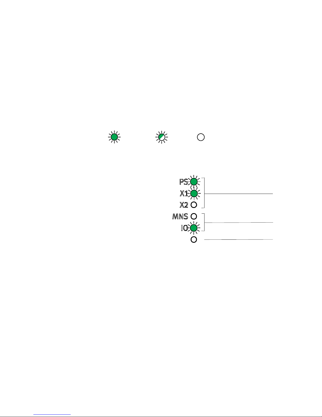
5. Diagnostics
5.2 Diagnostics via LED display
LEDs are located on the bus node for diagnosing the bus
node and any connected I-port devices Fig. 5/1.
The LEDs can assume the following states (sometimes in different colours):
Illuminates flashes off
5.2.1 Normal operating status display
Fieldbus/
1
network-specific
LEDs
2 CTEU-specific
LEDs
3 Reserved LED
display
Fig. 5/1: LEDs on the bus node
1
2
3
5-4
Festo P.BE-CTEU-DN-OP+MAINT-E N en 1206NH
Page 81
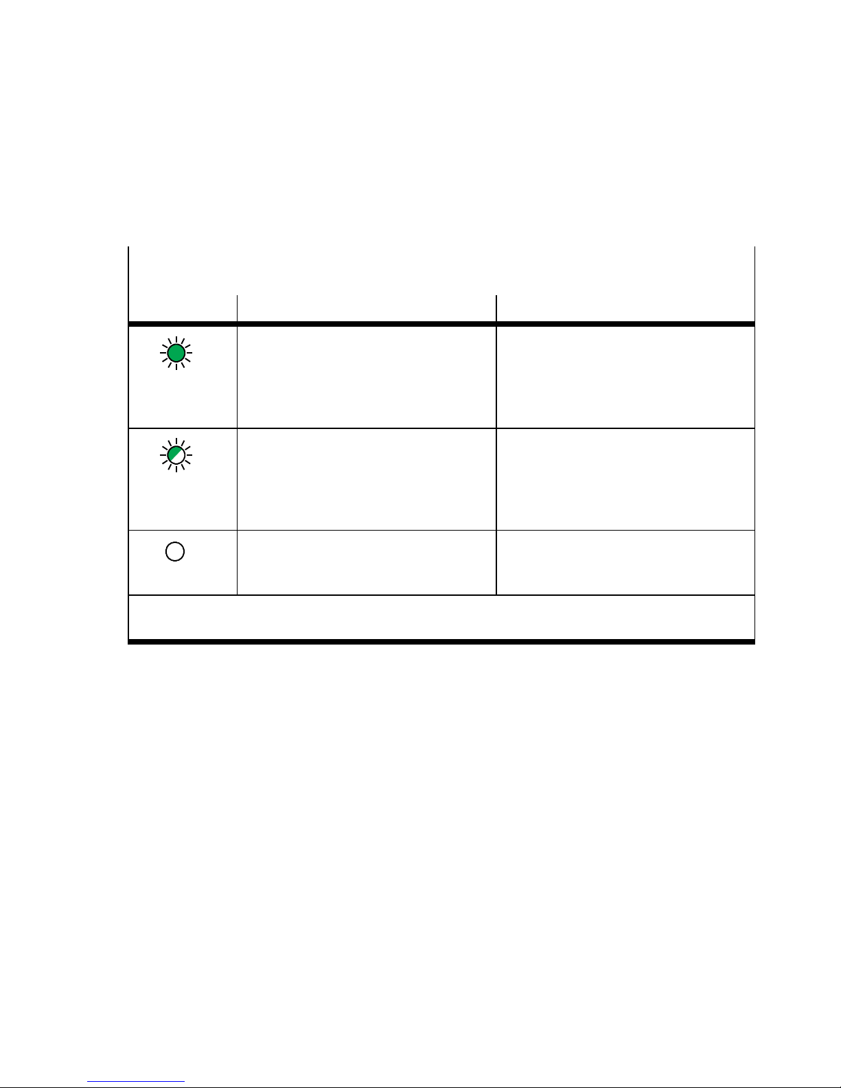
5. Diagnostics
5.2.2 PS-LED status display
PS status - Operating and load voltage supply
(Power System, Power Load)
LED display Status/significance Error handling
– Normal operating status
–
– Operating voltage applied
LED illuminated
green
LED flashes
green ( 1 Hz)
(in the approved range)
– Load voltage present ( in the ap-
proved range)
1)
– Operating voltage is below
the required voltage
– Load voltage is below
the required voltage
– Short circuit at the I-port
1)
1)
• Eliminate short circuit on the bus
node
• Eliminate undervoltage on the con-
nected I-port device
– Operating voltage not applied • Check the power supply
LED is off
1)
Display depends on whether the c onnected device monitors the load voltage and reports to the
bus node
Tab. 5/2: Status displays of the device-specific “PS” LED
Festo P.BE-CTE U-DN-OP+MAINT-EN en 1206NH
5-5
Page 82
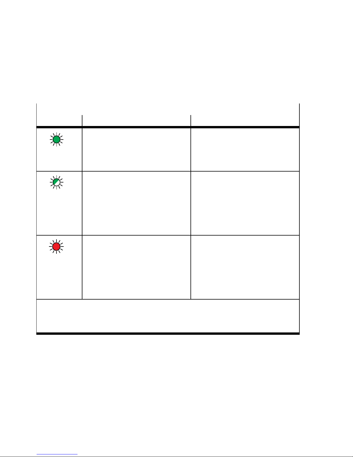
5. Diagnostics
5.2.3 Status display X1-/X2-LEDs
X1 or X21)– Internal communication between bus node and I-port device 1 or 2
LED display Status/significance Error handling
LED illuminated
green
LED flashes
green ( 1 Hz)
LED illuminated
red
– Normal operating status
– Device is correctly connected to the
bus node
– Operating and load voltage present
(in the approved range)
2)
– Connected I-port device reports dia-
gnostics status
– Diagnostics is running and/or dia-
gnostic data are being transferred.
– Undervoltage at system or additional
power supply
– Connection between bus node and
device is OK
– Device is connected correctly to the
bus node, but internal communication is faulty
– After commissioning, incorrect device
connected (non-I-port-compatible
device recognised)
– Device was removed after initializa-
tion of the bus node
–
• Read device diagnostics via fieldbus
communication (if activated via DI L
switches on the bus node)
• Eliminate undervoltage
• Check connection to
fieldbus/network:
Connecting cable, plug connector,
signal transmission, bus node,
PLC/scanner
• Check error counter for overflow
• Restart the bus node (switch voltage
on/off)
1)
1) Separate accessory with two interfaces for connecting another device is required, e.g.electrical
connection box CAPC-...
2)
Display depends on whether the c onnected device monitors the load voltage and reports to the
bus node
Tab. 5/3: Status displays of the device-specific LED “X1” and/or “X2” for co nnected
I-port devices – Part 1
5-6
Festo P.BE-CTEU-DN-OP+MAINT-E N en 1206NH
Page 83
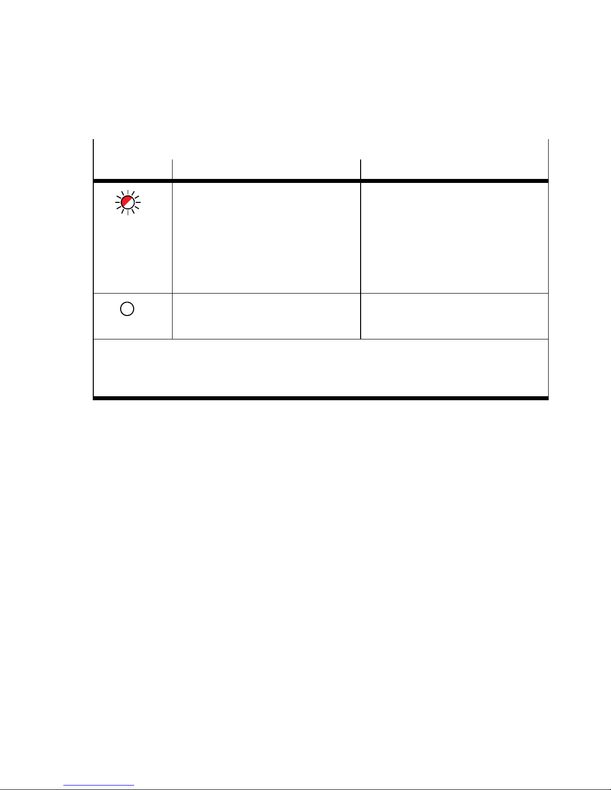
5. Diagnostics
X1 or X21)– Internal communication between bus node and I-port device 1 or 2
1)
LED display Status/significance Error handling
LED is flashing
red
– During commissioning, incorrect
device connected (non-I-port-compatible device recognised)
– If only LED X1 flashes red: error in the
bus node
• UseanI-portcompatibledevice(e.g.
valve terminal) from Festo
• Replace bus node
• IfX1andX2flashredsimultaneously:
connect I-port device
– If X1 and X2 flash red simultaneously:
no I-port device connected to the bus
node (at least one device is required)
– No device connected to the bus node
• ConnectI-portdevice
– Connection is bein g established
LED is off
1) S eparate accessory with two interfaces for connecting another device is required, e.g.electrical
connection box CAPC-...
2)
Display depends on whether the c onnected device monitors the load voltage and reports to the
bus node
Tab. 5/4: Status displays of the device-specific LED “X1” and/or “X2” for connected
I-port devices – Part 2
Festo P.BE-CTE U-DN-OP+MAINT-EN en 1206NH
5-7
Page 84
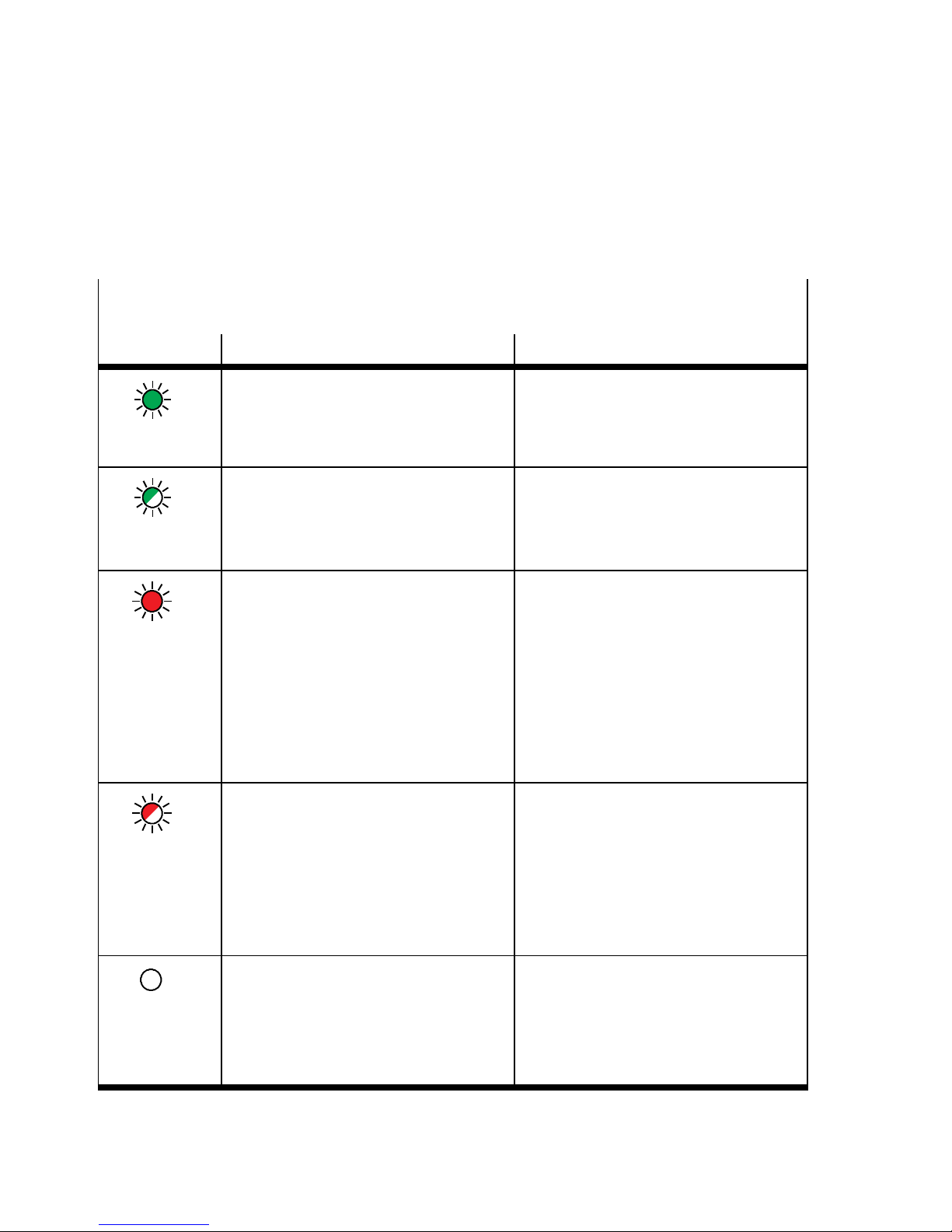
5. Diagnostics
5.2.4 Status display MNS- LED
MNS – Module status/network status
(Combined Module/Network Status)
LED display Status/significance Error handling
LED illuminated
green
LED flashes
green ( 1 Hz)
LED illuminated
red
LED is flashing
red
– Normal operating status (“online”)
– Communication with
fieldbus/network is OK
– Fieldbus/network communication
available (“online”), but not configured
– No fieldbus/network communication
(not available, “offline”, failed or invalid bus address or baud rate)
– No voltage supply to bus
– Communication error:
Fieldbus/network communication
disrupted, bus timeout detected or
no voltage supply to bus
–
• Check/configure fieldbus/network
communication
• Fieldbus/network is offline:
Establish connection
• Fieldbus/network error:
Check connection to fieldbus/network; connecting cable, plug connector , signal transmission, bus
node, PL C/scanner
• Check the setting of the DIL switches
• Check voltage supply to bus
Section 2.2.3
• Fieldbus/network error:
Check connection to fieldbus/network; connecting cable, plug connector , signal transmission, bus
node, PL C/scanner
• Check the setting of the DIL switches
• Check voltage supply to bus
Section 2.2.3
– No fieldbus/network connection: not
“online”,MAC-IDtest“DUB_MAC_ID”
LED is off
did not run successfully or no power
supply to bus
Tab. 5/5: Status displays of the network-specific “MNS” LED
5-8
• Establish/check fieldbus/network
connection
• Correct MAC-ID settin g
• Check the setting of the DIL switches
• Check voltage supply to bus
Section 2.2.3
Festo P.BE-CTEU-DN-OP+MAINT-E N en 1206NH
Page 85
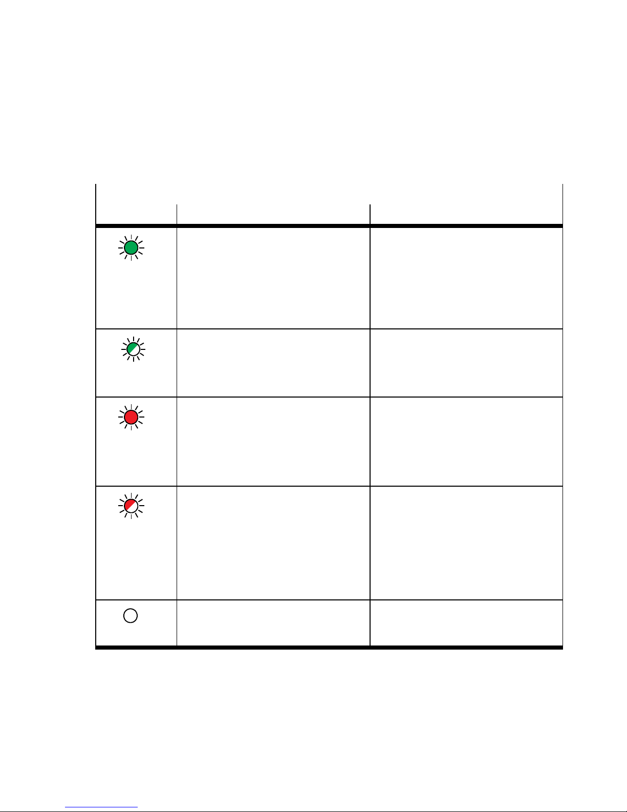
5. Diagnostics
5.2.5 I/O-LED status display
IO= I/O status, connection status
LED display Status/significance Error handling
LED illuminated
green
LED flashes
green (1 Hz)
LED illuminated
red
LED is flashing
red
– Normal operating status
– Communication with the controller
(PLC) OK
– Bus node is in operational mode and
is controlled by the PLC
– IOs are controlled via the PLC via
fieldbus/network
– Operating status in preparation
– Bus node is in pre-operational mode
– Inputs/outputs (IOs) are in idle state
mode
– Inputs/outputs (IOs) are in fail state
mode
– Typical cause:
usually an unrecoverable software
fault, e.g. no bus voltage
– Inputs/outputs (IOs) are in fail state
mode
– PLC failure or stop
– Incorrect station number in the PLC or
on the bus node (incorrect DIL switch
position)
– Fieldbus/network interruption or
message failure
–
–
• Check voltage supply to bus
Section 2.2.3
• Read device diagnostics via fieldbus
communication (if activated via DI L
switches on the bus node)
• Eliminate displayed faults
• Check PLC
• Check station number
Note
Station number (Node ID) 0 is not
permissible!
• Check fieldbus/network connection
– Fieldbus/I-port device not connected
– Commissioning of the bus node not
LED is off
complete or not successful
Tab. 5/6: Status displays of the fieldbus/network-specific “IO” LED
Festo P.BE-CTE U-DN-OP+MAINT-EN en 1206NH
• Connect fieldbus/I-port device
• Check fieldbus connection
• Restart
5-9
Page 86
5. Diagnostics
5.3 Reaction to malfunctions in the control system
The reaction of outputs and valves to control and communication malfunctions can be set via device-specific parameterisation Section 4.3.4.
In case of a malfunction, the network participants, i.e. the bus
nodes and the I-port devices, assume the parameterised fail
state mode.
Depending on the DIL switch setting, the inputs and outputs
hold the last state or reset to the basic state Tab. 2/7.
The selected setting applies for all outputs. (Factory setting:
“reset”).
Note
Pleasenotethefollowingvalvereactioniftheoutputsare
reset after PLC stop, network/fieldbus interruption or other
malfunction:
– Monostable valves mo ve to the basic position
– Double-solenoid valves remain in the current position
– Mid-position valves move to mid-position (pressurized,
exhausted or closed, depending on valve type).
Warning
Danger of injury.
• Make sure that outputs and valves are moved to a safe
state when malfunctions occur .
Incorrect output and valve states can cause dangerous
situations!
5-10
Festo P.BE-CTEU-DN-OP+MAINT-E N en 1206NH
Page 87

5. Diagnostics
5.4 Diagnostics via network/fieldbus
The following diagnostic functions are available:
– Diagnostics via the DeviceNet scanner
– Diagnostics via the configuration software
(e.g. RSNetWorx)
– Diagnostics via a user program
5.4.1 Diagnostics via configuration software
1. Make sure that the bus node is “online”.
2. Double-click the CTEU-DN symbol in the configuration
software (e.g. RSNetWorx).
3. Click on the “Parameters” tab.
4. Double click on the “Status Byte” parameter line.
Detailed information is displayed Fig. 5/2.
Additional information can be found in Tab. 5/7.
Festo P.BE-CTE U-DN-OP+MAINT-EN en 1206NH
5-11
Page 88
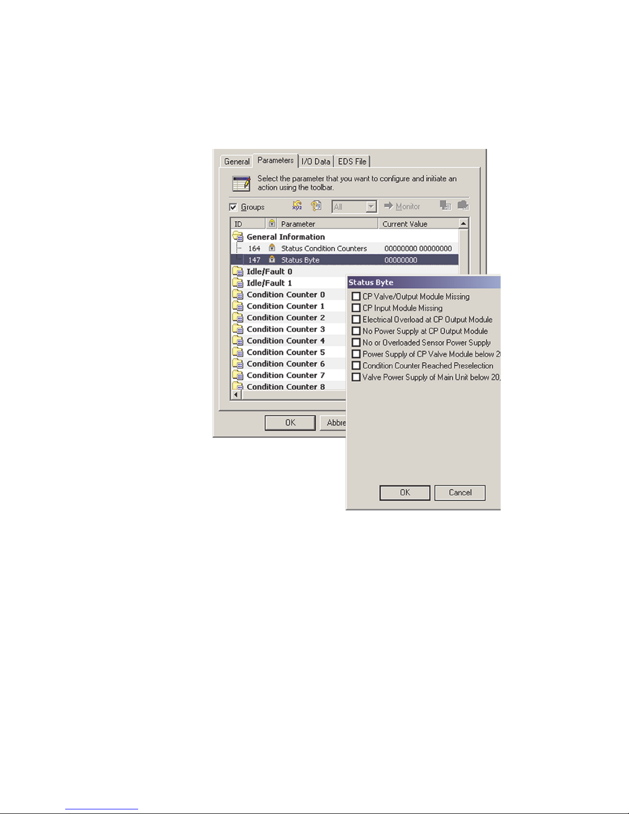
5. Diagnostics
5-12
Fig. 5/2: Display of detailed diagnostics information
(example – explanations Tab. 5/7)
Festo P.BE-CTEU-DN-OP+MAINT-E N en 1206NH
Page 89
5. Diagnostics
The table below shows the composition of the diagnostic information (status byte). Additional information can be found
in the Appendix.
Bit
0 I-Port Module Error I-port device/module reports diagnostics status
1 I-Port Configuration Error – Connected device/module is not c ompatible with
2 Communication Error I-port communication error during operation, e.g. if
3 Undervoltage PS Undervoltage in the power supply
4 Undervoltage PL I-port device/module reports undervoltage in the load
5 Overload/Short Circuit Module I-port device/module reports short circuit or overload
6 Overload/Short Circuit I-Port Short circuit or overload at I-port
7 Other Error Other faults:
Significance Explanation
I-port
– I-port device/module interchanged during opera-
tion
– I/O data length not reached/exceeded
the I-port device/module was unplugged
supply
T ab. 5/7: Explanation on the diagnostic information (significance of I-port status byte –
Festo diagnostic object – Class code 103
5.4.2 Short circuit/overload
Festo P.BE-CTE U-DN-OP+MAINT-EN en 1206NH
)
d
Short circuit or overload monito ring depends on the connected I-port device: When the I-port device monitors the load
voltage and I-port connection for short circuit and overload,
corresponding error messages are generated and forwarded
to the PLC. On the bus node, the “PS” LED flashes green,
showing a malfunction in the operating and load voltage supply ( Tab. 5/2).
More extensive information can be found in the product documentationontheI-portdevice.
5-13
Page 90

5. Diagnostics
5-14
Festo P.BE-CTEU-DN-OP+MAINT-E N en 1206NH
Page 91

Error handling
Chapter 6
Error handling
6-1Festo P.BE-CTE U-DN-OP+MAINT-EN en 1206NH
Page 92

6. Error handling
Contents
6. Error handling 6-1.................................................
6.1 Fault finding and error elimination 6-3.................................
6.1.1 Check installation 6-3.......................................
6.1.2 Check the power supply 6-4..................................
6.1.3 Restart communication between the bus node and the device 6-5...
6.1.4 Check fieldbus communication 6-5.............................
6.1.5 Check DeviceNet configuration 6-6.............................
6.1.6 Read out diagnostic messages via DeviceNet 6-7.................
6-2
Festo P.BE-CTEU-DN-OP+MAINT-E N en 1206NH
Page 93

6. Error handling
6.1 Fault finding and error elimination
This section is meant as a checklist to help you inspect your
installation and commissioning steps if an error occurs. You
will find information on fault finding and error elimination, as
well as references to the respective chapters of the two-part
product documentation on the bus node.
Eliminate individual sources of error by running the following
checks in the specified order.
6.1.1 Check installation
• Check the mechanical and electrical installation of the bus
node on the I-port device or the electrical connection box
and the correct earthing of all of the components involved.
• Check whether all the required connection lines and con-
necting cables are fitted correctly .
• Carefully check potential l y faulty lines and cables.
• Replace any visibly damaged lines and cables.
Information relating to installing the bus node can be found in
Part I of the product documentation entitled “Installation and
Interface manual”, which is supplied with the bus node.Information for mounting the bus node on the electrical connection box CAPC-... can be found in the assembly instructions
supplied with the electrical connection box.
Festo P.BE-CTE U-DN-OP+MAINT-EN en 1206NH
6-3
Page 94
6. Error handling
6.1.2 Check the power supply
Warning
• Use only PELV circuits for the electrical power supply in
accordance with IEC/EN 60204-1
(Protective Extra-Low Vo l tage, PELV).
• Observe also the general requirements for PELV circuits
in accordance with IEC/EN 60204-1.
• Useonlyvoltagesourcesthatensureareliableelectric
separation of operating voltage in accordance with
IEC/EN 60204-1.
• Always connect both circuits for operating and load
voltage supply.
• Check to make sure both power supplies for the operat-
ing and load voltage are connected.
Note
The devices connected to the bus node are powered exclusively via the load voltage connection.
• Check the pin assignment of self-assembled cables.
Information relating to installing the bus node can be found in
Part I of the product documentation entitled “Installation and
Interface manual”, which is supplied with the bus node.
Normal status LED PS-LED illuminates green and the X1-L ED and/or X2-LED illu-
minate green.
Error status 1 The operating voltage supply for the bus node exhibits under-
voltage:
6-4
– PS-LED flashes green
Festo P.BE-CTEU-DN-OP+MAINT-E N en 1206NH
Page 95

6. Error handling
Error status 2 The load voltage supply for the connected device is missing
or exhibits undervoltage:
– PS-LED flashes green
and
– X1 and/or X2-LED flash green
Note
Requirement for diagnostics via LED display:
The connected device must support this diagnostic function.
(Additional information can be found in the respective device
description).
6.1.3 Restart communication between the bus node and the device
Problem description: X1 and X2 flash red simultaneously.The check of the mechani cal
connection between bus node and device (dismantling/installing) effected no change. The fault cannot be eliminated in
this way.
Remedy Proceed as follows:
1. Disconnect the operating vol tage.
2. Check, sever and re-establish the electrical connection
between the bus node and connected devices.
3. Restore voltage.
X1 and/or X2 illuminate or flash green.
6.1.4 Check fieldbus communication
• Compare the desired baud rate with the baud rate set on
the bus node (DIL switch setting).
Festo P.BE-CTE U-DN-OP+MAINT-EN en 1206NH
• Compare the desired station number (NodeID) with the
station number set on the bus node (DIL switch setting).
6-5
Page 96

6. Error handling
Information relating to installing the bus node can be found in
Part I of the product documentation entitled “Installation and
Interface manual”, which is supplied with the bus node.
• Compare your cable lengths with the technical data in the
Attachment and the recommendation in the CiA specification ( Tab. 2/8).
• Test the fieldbus communication using the object direct-
ory ( Appendix A.4).
Normal status LED MNS-L ED is off and I/O-LED illuminates green (in operational
mode).
MNS-LED is off and I/O-LED is off (if no fieldbus communication).
6.1.5 Check DeviceNet configuration
Problem description: Process data are defective.
Remedy Proceed as follows:
1. Check whether the I/O mapping matches the controller
settings ( Appendix A.4).
2. Check whether the bus node status, e.g. operational
mode, matches the controller settings ( Section 5.2.5).
Problem description: Outputs do not switch to the desired state if fieldbus commu-
nication is disrupted.
Remedy Proceed as follows:
1. Check whether fail state mode or idle state mode is activated in the controller.
6-6
This ensures that the bus node can detect disrupted fieldbus communication and that the outputs are set to a
defined state after fieldbus communication is restored
(network communication).
Festo P.BE-CTEU-DN-OP+MAINT-E N en 1206NH
Page 97

6. Error handling
2. Check whether Fail State is activated on the bus node (DIL
switch position).
Fail state mode off (reset):
The outputs are reset to “0” after fieldbus communication
is restored.
Fail state mode on (hold last state):
Once fieldbus communication is restored, the outputs
resume their state prior to failure.
6.1.6 Read out diagnostic messages via DeviceNet
Problem description: Th e previous checks are “fruitless”, i.e. provide no informa-
tion about the cause of the fault.
Remedy: Read out diagnostic messages via DeviceNet.
Requirement: The I-port devices connected to the bus nodes can offer
advanced diagnostic options.
Additional prerequisites:
– Diagnostic mode is activated:
Check the DIL switch setting.
– Network connection to the connected I-port device is
available:
X1 or X2-LED flashes green.
Proceed as follows:
Evaluate the diagnostic information in the process data (see
Section 5.3).
Festo P.BE-CTE U-DN-OP+MAINT-EN en 1206NH
6-7
Page 98

6. Error handling
6-8
Festo P.BE-CTEU-DN-OP+MAINT-E N en 1206NH
Page 99

Technical appendix
Appendix A
Technical appendix
A-1Festo P.BE-CTEU-DN-OP+MAINT-EN en 1206NH
Page 100

A. Technical appendix
Contents
A. Technical appendix A-1.............................................
A.1 Technical data A-3..................................................
A.1.1 General properties A-3......................................
A.1.2 Power supply A-6...........................................
A.1.3 Signal transmission A-7......................................
A.2 Terms and abbreviations A-8.........................................
A.3 F ai l state behaviour A-11.............................................
A.4 DeviceNet object model A-13..........................................
A.4.1 DeviceNet Object model for CTEU-DN – overview A-13..............
A.4.2 Participant features (Identity object) A-16........................
A.4.3 DeviceNet object A-17........................................
A.4.4 Assembly Object A-18........................................
A.4.5 Discrete output byte object A-19...............................
A.4.6 Discrete input byte object A-20.................................
A.4.7 Festo diagnostic object (I-port status byte) A-21...................
A.4.8 Festo module object A-23.....................................
A.4.9 Festo system object A-24......................................
A.4.10 Festo parameter object A-25...................................
A-2
Festo P.BE-CTEU-DN-OP+MAINT-E N en 1206NH
 Loading...