

Page 1
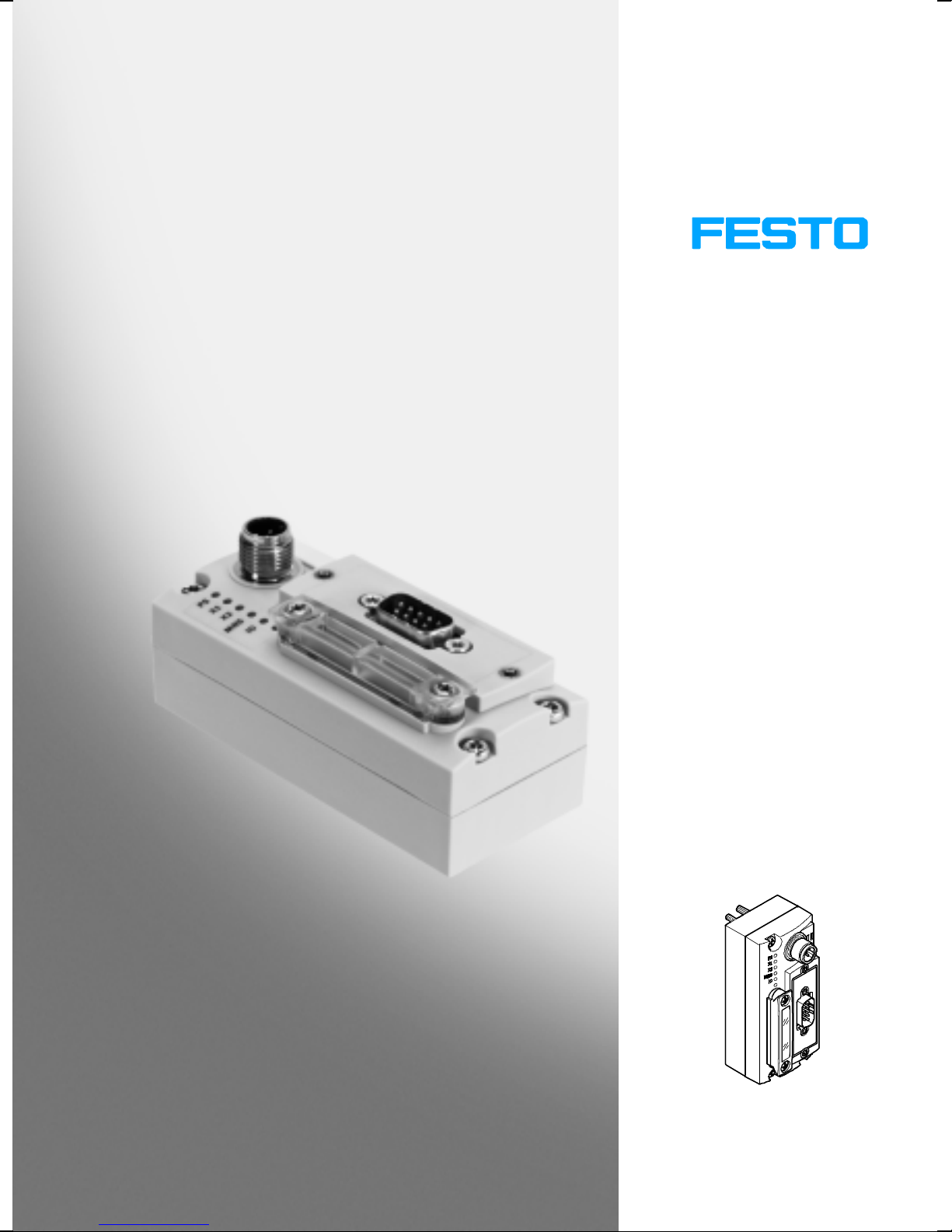
Universal bus node
CTEU-CO
Manual
Functions and
maintenance
Bus node
Type CTEU-CO
Fieldbus Protocol
CANopen
Manual
573 768
en 1101NH
[756 466]
Page 2

Page 3

Installation
Original de.......................................
Edition en 1101NH.................................
Designation P.BE-CTEU-CO-OP+MAINT-EN..............
Order no. 573 768.................................
© (Festo AG & Co. KG, D-73726 Esslingen, 2011)
Internet: http://www.festo.com
E-Mail: [email protected]
The reproduction of this document and disclosure to third
parties and the utilisation or communication of its contents
without explicit authorization is prohibited. Offenders will
be held liable for compensation of damages. All rights
reserved, in particular the right to carry out patent, utility
model or ornamental design registrations.
Festo P.BE-CTEU-CO-OP+MAINT-EN en 1101NH
I
Page 4

Installation
CANopen®,CiA®,TORX®,TÜV®and VDE®are registered trademarks of the respective
trademark owners in certain countries.
II
Festo P.BE-CTEU-CO-OP+MAINT-EN en 1101NH
Page 5

Installation
Contents
Intended use V..........................................................
Range of application and certifications VI.....................................
Target group VI..........................................................
Service VI...............................................................
Notesonthismanual VII...................................................
Important user instructions VIII..............................................
1. Commissioning 1-1................................................
1.1 General information about the CANopen fieldbus protocol 1-3.............
1.1.1 Components 1-3............................................
1.1.2 Data exchange with the CANopen fieldbus protocol 1-4............
1.1.3 CANopen specifications 1-4..................................
1.1.4 Brief overview of the scope of functions 1-5.....................
1.2 Commissioning of a master controller 1-6..............................
1.2.1 Installing the EDS file 1-6....................................
1.3 Configuration by using process data 1-7...............................
1.3.1 Predefined process data for establising connections 1-7...........
1.3.2 Rules for internal I/O mapping 1-8.............................
1.3.3 I/O linking by COB-IDs 1-8...................................
1.4 Device parameters 1-10..............................................
1.5 Communication 1-11................................................
1.5.1 Structure of communication 1-11...............................
1.5.2 CANopen status transiti o ns 1-12...............................
1.5.3 Examples of the communication sequence 1-14...................
1.6 Switching on 1-18...................................................
1.6.1 Information concerning the switch-on behaviour of the bus node 1-18.
1.6.2 Switching on the operating voltage 1-19.........................
1.6.3 Normal operating status 1-20..................................
1.7 Fail state behaviour 1-21.............................................
Festo P.BE-CTEU-CO-OP+MAINT-EN en 1101NH
III
Page 6

Installation
2. Diagnosis 2-1.....................................................
2.1 Summary of diagnostics options 2-3...................................
2.2 Diagnostics via LED display 2-4.......................................
2.2.1 Normal operating status display 2-5...........................
2.2.2 PS-LED status display 2-5....................................
2.2.3 Status display X1-/X2-LEDs 2-6...............................
2.2.4 Status display MNS-L ED 2-7..................................
2.2.5 I/O-LED status display 2-8....................................
2.3 Diagnostics via fieldbus 2-9..........................................
2.3.1 Diagnostics via SDO 2-9.....................................
2.3.2 The Emergency Message 2-9..................................
2.3.3 Reaction to network communication faults 2-13...................
2.3.4 Node guarding 2-13..........................................
3. Error treatment 3-1................................................
3.1 Fault finding and error elimination 3-3.................................
3.1.1 Check the installation 3-3....................................
3.1.2 Check the power supply 3-4..................................
3.1.3 Restart communication between the bus node and the device 3-5...
3.1.4 Check fieldbus communication 3-5.............................
3.1.5 Check the CANopen configuration 3-6..........................
3.1.6 Read out diagnostic messages via CANopen 3-7.................
A. Technical appendix A-1.............................................
A.1 Technical data A-3..................................................
A.2 Object directories A-6...............................................
B. Index B-1.........................................................
IV
Festo P.BE-CTEU-CO-OP+MAINT-EN en 1101NH
Page 7

Installation
Intended use
The bus node type CTEU-CO described in this manual has
been designed exclusively for use as a slave on the CANopen
field bus.
Thebusnodemayonlybeusedasfollows:
–asintended
– in original condition, without any modifications by the
user.
Only the conversions or modifications described in the
docume nt at i o n supplied with the product are permitted.
– in perfect technical condition.
The limit values specified for pressures, temperatures,
electrical data, torques etc. should be observed.
Observe the regulations of the trade associations, German
T echnical Control Board (TÜV), VDE stipulations or corresponding national laws and regulations.
Warning
• Use only PELV circuits as per IEC/EN 60204-1 for the
electric power supply (protective extra-low voltage,
PELV).
Also observe the general requirements for PELV circuits
in accordance with IEC/EN 60204-1.
• Use only power sourcesth at guarantee reliable electrical
isolation of the operating voltage as per IEC/EN 60204-1.
Protection against electri c shock (protection against direct
and indirect contact) is guaranteed in accordance with
IEC/EN 60204-1 by using PELV circuits (electrical equipment
of machi nes, general requirements).
Festo P.BE-CTEU-CO-OP+MAINT-EN en 1101NH
V
Page 8

Installation
Range of application and certifications
The product fulfils the requirements of the EU directives and
is marked with the CE certification.
Standards and test values which the product must comply
with and fulfil can be found in the section “Technical appendix”. The product-relevant EU directives can be found in
the declaration of conformity.
Certificates and declarations of conformity for this product
can be found at www .festo.com.
Target group
Service
This manual is intended exclusively for techni cians trained in
control and automation technology who have experi ence in
installing, commissioning, programming and diagnosing
programmable logic controllers (PLCs) and slaves on the
CANopen fieldbus.
Please consult your local Festo Service if you have any technical problems.
VI
Festo P.BE-CTEU-CO-OP+MAINT-EN en 1101NH
Page 9

Installation
Notesonthismanual
This manual is Part II of the complete product documentation
and contains specific information about the configuration,
parameterisation, commissioning, programming and
diagnostics of the bus node with the CANopen fieldbus
protocol.
Information relating to installing the bus node can be found in
Part I of the product documentation entitled “Installation and
Interface manual”, which is supplied with the bus node.
Information for mounting the bus node on the CAPC… electri c
sub-base can be found in the assembly instructions supplied
with the electric sub-base.
Information about other bus nodes and components of the
CTEU… product family can be found in the user documentation for the respective product.
Festo P.BE-CTEU-CO-OP+MAINT-EN en 1101NH
VII
Page 10
Installation
Important user instructions
Danger categories
This manual contains instructions on the possible dangers
which may occur if the product is not used correctly. These
instructions are marked (Warning, Caution, etc.), printed on a
shaded background and marked additionally with a pictogram.
A distinction is made between the following danger warnings:
Warning
This means that failure to observe this instruction may
result in serious personal injury or damage to property.
Caution
This means that failure to observe this instruction may
result in personal injury or damage to property.
Note
This means that failure to observe this instruction may
result in damage to property .
The following pictogram marks passages in the text which
describe activities with electrostatically sensitive components.
Electrostatically sensitive components may be damaged if
they are not handled correctly.
VIII
Festo P.BE-CTEU-CO-OP+MAINT-EN en 1101NH
Page 11

Installation
Marking special information
The following pictograms mark passages in the text
containing special information.
Pictograms
Information:
Recommendations, tips and references to other sources of
information.
Accessories:
Information on necessary or sensible accessories for the
Festo product.
Environment:
Information on environment-friendly use of Festo products.
Text markings
• The bullet indicates activities which may be carried out in
any order.
1. Figures denote activities which must be carried out in the
numerical order specified.
– Hyphens indicate general activities.
Festo P.BE-CTEU-CO-OP+MAINT-EN en 1101NH
IX
Page 12
Installation
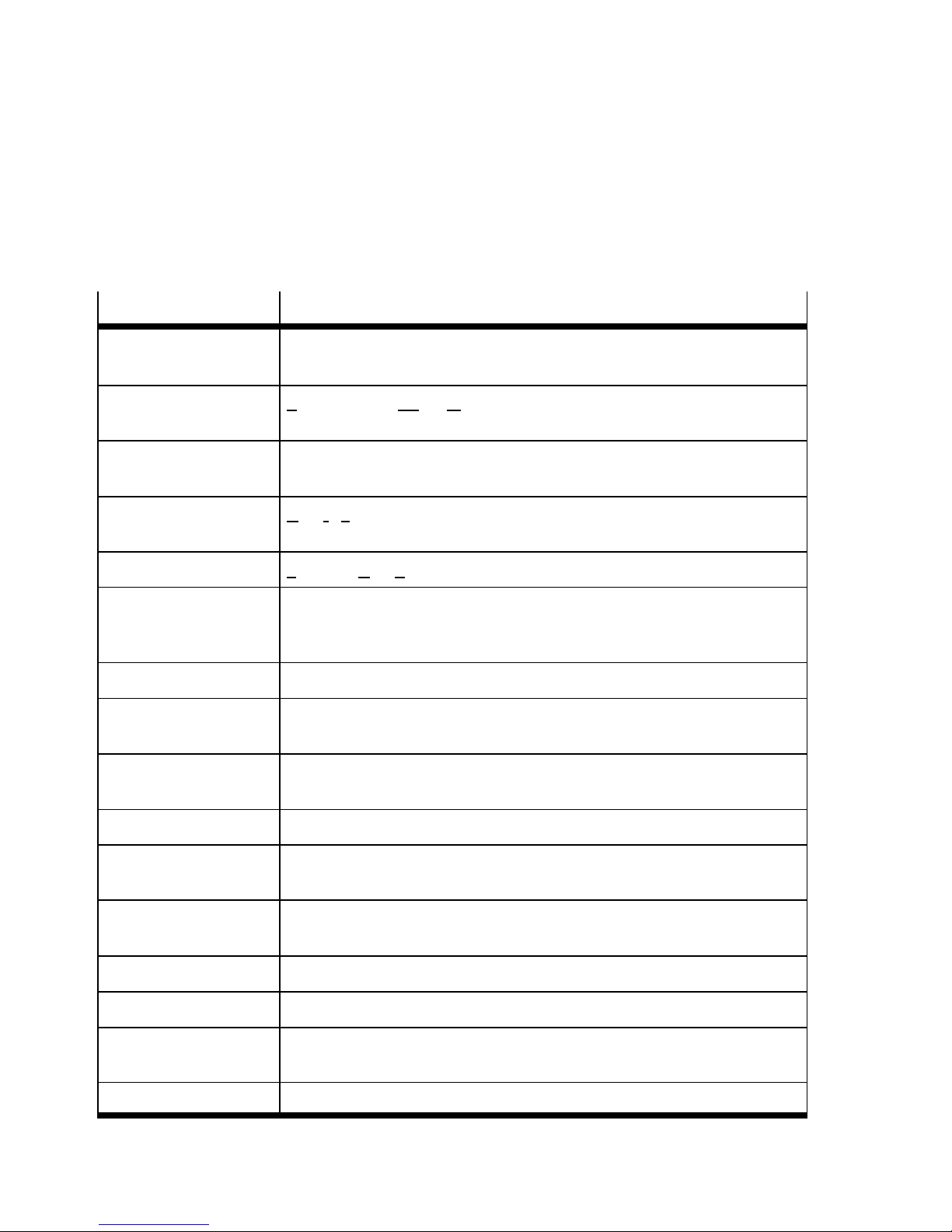
The following product and fieldbus-specific terms and abbreviations are used in this manual:
Term/abbreviation
Bus nodes create the connection to c ertain field busses/networks, pass on control
COB-ID Communication Object Identifiers consist of the function code and
DCF Device Con figuration File = these files contain additional project data
DIL switches Dual-In-Line switches usually consist of several switching elements which
EDS Electronic Data Sheets include product-specific data about the bus node.
Fail state This is a function which automatically activates the “Hold last state”
F0
h
Heartbeat The bus node sen ds a telegram cyclically to the network which can be
Meaning
signals to the connected devices/modules and monitor their functioning.
address of the activated field bus slave (Node ID) .
which extends beyond EDS content/scope.
can be used to implement hardware settings.
function in the event of an abortion of the network connection, and it is
also designated “fail safe” in some cases.
Hexadecimal numbers are marked by a low-set “h”.
monitored by any station, compare with node guarding.
Hold last state defines the status which outputs/valves are to assume after field bus
and/or communication errors
I/Os Digital inputs and outputs
Load voltage includes the power supply for connected devices and (digital) outputs,
e. g. solenoid coils of valves
Node guarding Cyclic monitoring of the fieldbus station by the master controller by
requesting a response within a specified time period.
Node ID Address of the fieldbus station
OB Output byte
Object Directory makes all important slave parameters accessible in a standardised
manner
O, I Digital output, digital input
X
Festo P.BE-CTEU-CO-OP+MAINT-EN en 1101NH
Page 13

Installation
T erm/abbreviation Meaning
Operating voltage also referred to as signal voltage: includes the power supply for
electronics and sensors
PDO Process Data Objects serve for the fast transfer of processing data via
Multicast connection and are transmitted by simple CAN messages
without protocol overhead. Process Data Objects c an be transmitted
event-controlled, synchronous to a system pulse sequence or on demand.
PDOs are divided into TPDOs and RPDOs.
PLC/IPC Programmable logic controller/industrial PC
RPDO Receive PDO
SC/O
SCS, SCO, SCV
SDO Service Data Objects predominantly form point-to-point connections
Status bits Internal inputs which supply coded common diagnostic messages.
TPDO Transmit-P DO
Voltage supply Umbrella term for operating and load voltage supplies
Short circuit/overload
Short circuit/overload sensor supply, outputs, valves
between the server and client for the exchange of parameters for device
configuration. They enable write and read access to any entry in the object
directory of a bus node.
T ab . 0/1: Terms and abbreviations
Festo P.BE-CTEU-CO-OP+MAINT-EN en 1101NH
XI
Page 14

Installation
XII
Festo P.BE-CTEU-CO-OP+MAINT-EN en 1101NH
Page 15

Commissioning
Chapter 1
Commissioning
1-1Festo P.BE-CTEU-CO-OP+MAINT-EN en 1101NH
Page 16

1. Commissioning
Contents
1. Commissioning 1-1................................................
1.1 General information about the CANopen fieldbus protocol 1-3.............
1.1.1 Components 1-3............................................
1.1.2 Data exchange with the CANopen fieldbus protocol 1-4............
1.1.3 CANopen specifications 1-4..................................
1.1.4 Brief overview of the scope of functions 1-5.....................
1.2 Commissioning of a master controller 1-6..............................
1.2.1 Installing the EDS file 1-6....................................
1.3 Configuration by using process data 1-7...............................
1.3.1 Predefined process data for establising connections 1-7...........
1.3.2 Rules for internal I/O mapping 1-8.............................
1.3.3 I/O linking by COB-IDs 1-8...................................
1.4 Device parameters 1-10..............................................
1.5 Communication 1-11................................................
1.5.1 Structure of communication 1-11...............................
1.5.2 CANopen status transiti o ns 1-12...............................
1.5.3 Examples of the communication sequence 1-14...................
1.6 Switching on 1-18...................................................
1.6.1 Information concerning the switch-on behaviour of the bus node 1-18.
1.6.2 Switching on the operating voltage 1-19.........................
1.6.3 Normal operating status 1-20..................................
1.7 Fail state behaviour 1-21.............................................
1-2
Festo P.BE-CTEU-CO-OP+MAINT-EN en 1101NH
Page 17
1. Commissioning
1.1 General information about the CANopen fieldbus protocol
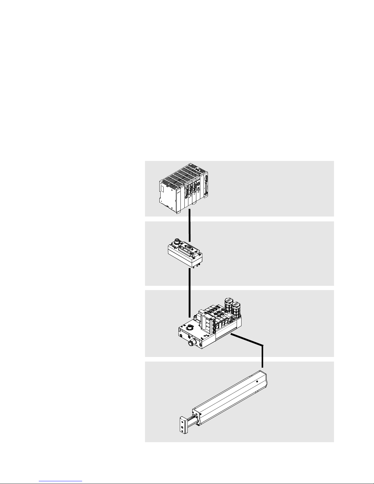
The CTEU… product family enables the creation of a decentralised automation system in a CANopen fieldbus network.
1.1.1 Components
Higher-order
1
controller
(CAN master):
e.g. CECX
1
2 Fieldbus level:
CTEU bus node
3 Device level:
e.g. valve
terminal VTUB-12
4 Drive level:
e.g. linear
module HME
2
3
4
Festo P.BE-CTEU-CO-OP+MAINT-EN en 1101NH
1-3
Page 18

1. Commissioning
1.1.2 Data exchange with the CANopen fieldbus protocol
Communication profile The fieldbus protocol uses a communication profile (docu-
mented in CiA DS301, see Tab. 1/1) to regulate how data is
exchanged among the fieldbus stations. A distinction is made
between real-time data and parameter data in this process.
Object directory CANopen devices have an object directory which makes all
important slave parameters accessible in a standardised
manner. A CANopen system is essentially configured by accessing the objects in the object directory of the individual
fieldbus stations.
SDO, PDO The data exchange in CANopen is in the form of telegrams
with which the work data is transmitted. A distinction is made
between low-priority Service Data Objects (SDO), which are
used for transmitting service data from and to the object directory, and between high-priority Process Data Objects
(PDO), which serve for the fast transfer of current process
states. In addition, Network Management Telegrams (NMT),
among others, are used for managing the fieldbus network
and global fault messages.
1.1.3 CANopen specifications
The following specifications are supported by the bus node:
CANopen specifications
DS201
DS207
DS301, V4.0.2 The Draft Standard301isbasedontheCAL
CAN Application Layer CAL
communicationprofile
Tab. 1/1: Supported CANopen specifications
1-4
DS401, V3.0 The Draft Standard 401 defines the device
profiles for input and output modules within
CANopen
Festo P.BE-CTEU-CO-OP+MAINT-EN en 1101NH
Page 19

1. Commissioning
Correct commissioning of the bus node requires you to be
familiar with CANopen and be acquainted with the
above- mentioned specifications.
1.1.4 Brief overview of the scope of functions
– Module states and boot-up as per Communication Profile
DS301
– 1 Service Data Object for read and write access to the
object directory: Send and Receive SDO
– 2 Process Data Objects for access to digital inputs:
Transmit PDO 1 and 2
– 2 Process Data Objects for access to digital outputs:
Receive PDO 1 and 2
– Emergency telegram for fault message to the master
controller
– Node guarding and Heartbeat
– Default setting of all identifiers as per DS301 and the
station number (predefined connection set)
– Variable mapping
Festo P.BE-CTEU-CO-OP+MAINT-EN en 1101NH
1-5
Page 20

1. Commissioning
1.2 Commissioning of a master controller
1.2.1 Installing the EDS file
Electronic Data Sheets (EDS), which are accessible via the
network and describe the features and functions of the bus
node, are available for configuring the master controller (also
designated “CAN-Master”).
ThecurrentEDSfilecanbefoundontheFestowebsiteat
www.festo.com Support/Downloads.
Install this file by using the configuration software of your
master controller. Please refer to the manuals for this software for detailed procedures.
1-6
Festo P.BE-CTEU-CO-OP+MAINT-EN en 1101NH
Page 21

1. Commissioning
1.3 Configuration by using process data
1.3.1 Predefined process data for establising connections
The bus node can use up to two PDO telegrams for process
data (Fig. 1/1), for both inputs (TxPDO) and outputs (RxPDO).
Both telegrams are continuously filled with process data of
one or two connected devices (max. 2 x 8 bytes = 128 logical
I/Os for inputs and outputs).
Transmit PDO 1 I0 … E7 I8 … I15 I16 …
I23
Transmit PDO 2 I64 …
I71
Receive PDO 1 O0 …
O7
Receive PDO 2 O64 …
O71
I72 …
I79
O8 …
O15
O72 …
O79
I80 …
I87
O16 …
O23
O80 …
O87
I24 …
I31
I88 …
I95
O24 …
O31
O88 …
O95
Fig. 1/1: Overview of PDO 1 and 2 for inputs and outputs
Note
When filling the process data telegrams please note that
CANopen specification DS401 is only observed if you fill
PDO 1 exclusively with input and output bytes.
I32 …
I39
I88 …
I95
O32 …
O39
O88 …
O95
I40 …
I47
I104 …
I111
O40 …
O47
O104 …
O111
I48 …
I55
I112 …
I119
O48 …
O55
O112 …
O119
I56 …
I63
I120 …
I127
O56 …
O63
O120 …
O127
Festo P.BE-CTEU-CO-OP+MAINT-EN en 1101NH
1-7
Page 22

1. Commissioning
1.3.2 Rules for internal I/O mapping
The following rules are applied when using the PDOs:
– The telegrams are filled in ascending order.
– Mapping can be used individually via both PDOs.
– The inputs and outputs are factory-arranged according to
the standard mapping function.
– The I/Os are arranged according to the standard mapping
function when a device is connected and the bus node is
switched on.
– Process data allocation between the bus node and valve
terminal remains in effect even if the two modules are
separated, provided that the bus node remains under
voltage during the separation. Otherwise the mapping
information of connected devices is deleted.
1.3.3 I/O linking by COB-IDs
COB-IDs are made up of the function code (see Tab. 1/3) and
the address of the respective fieldbus station (Node ID):
10
Function Code Node ID
T ab . 1/2: Configuration of COB-IDs
9 8 7 6 5 4 3 2 1 0
1-8
Festo P.BE-CTEU-CO-OP+MAINT-EN en 1101NH
Page 23

1. Commissioning
Object Object designation ValuerangeoftheCOBidentifier
1)
SYNC
Broadcast object 080
128
h
d
EMERGENCY For procedures with high
priority,e.g.undervoltage
080
128
Transmit PDO 1 PDO1 (tx) 181
385d… 511
Transmit PDO 2 PDO2 (tx) 281
641d… 767
Receive PDO 1 PDO1 (rx) 201
513d… 639
Receive PDO 2 PDO2 (rx) 301
769d… 895
Transmit SDO SDO1 (tx) 581
1409d… 1535
Receive SDO SDO1 (rx) 601
1537d… 1663
Node guarding /
Heartbeat
1)
“0”isusedastheNodeID.
Cyclic interrogation (guarding)
or life sign message:
701
1793d… 1919
h
d
h
h
h
h
h
h
h
1FF
2FF
27F
37F
5FF
67F
77F
h
d
h
d
h
d
h
d
h
d
h
d
h
d
T ab . 1/3: Function Code
Festo P.BE-CTEU-CO-OP+MAINT-EN en 1101NH
Examples for using the COB-IDs can be found in section 1.5.3.
1-9
Page 24

1. Commissioning
1.4 Device parameters
Identification information for connected devices is stored in
the object directory of the bus node in object 3101 for a
device connected to I-Port 1 or in object 3102 for a device
connected to I-Port 2.
Extended device parameters are available via SDO access to
object 3301 for a device connected to I-Port 1 or object 3302
for a device connected to I-Port 2.
Information about the structure of the device parameters can
be fo und in the appendix , section A, and in the documenta ti on
foryourdevice.
1-10
Festo P.BE-CTEU-CO-OP+MAINT-EN en 1101NH
Page 25

1. Commissioning
1.5 Communication
When the fieldbus stations are switched on they all assume
the “pre-operational” status and wait for instruction from the
master controller.
1.5.1 Structure of communication
Pre-operational Only SDOs can be parameterised in this status. This paramet-
erisation corresponds to the asynchronous transmission
which is standard with most PLC controllers. Conversion to
e.g. synchronous transmission is possible if the communication parameters are written with the appropriate values from
the DS301 communication profile, but modifying the mapping
is not possible.
Operational After successful parameterisation the master controller can
switch the fieldbus stations to the “operational” status with a
special Network Management Telegram (NMT).
Communication via both SDOs and PDOs is possible in this
status. With the aid of the NMT tel egrams you can switch
between the different states, if required.
Festo P.BE-CTEU-CO-OP+MAINT-EN en 1101NH
1-11
Page 26
1. Commissioning
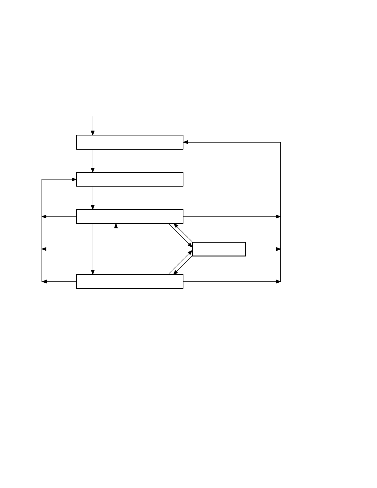
1.5.2 CANopen status transitions
Power On
Application initialisation
0
0
Communication initialisation
4
0
0
5
Pre-operational
2
1
2
3
Stopped
3
1
Operational
Fig. 1/2: CANopen status transitions (for a description refer to T ab. 1/4)
1-12
Festo P.BE-CTEU-CO-OP+MAINT-EN en 1101NH
Page 27

1. Commissioning
0
Description of the status transitions
Status
Designation Command
transition
0
1 Start_Remote_
2 Enter_Pre_
3 Stop_Node_
– –
Node_Indication
Operation_State_
Indication
Indication
Specifier (cs)
01
h
80
h
02
h
Function
Automatic boot-up after power on
The saved parameters 2000 … 5F FF are only
loaded after power on
Starts the bus node in operational mode:
– SDO transmission valid
– PDO transmission (outputs active)
– Node guarding / Heartbeat valid
(Node guarding response: Toggle + 05
Bus node in pre-operational mode:
– SDO transmission valid
– PDO transmission invalid
(Outputs assume error status
– Node guarding / Heartbeat valid
(Node guarding response: Toggle + 7F
Bus node in stopped mode:
– SDO transmission invalid
– PDO transmission invalid
(Outputs assume error status
– Node guarding / Heartbeat valid
(Node guarding response: Toggle + 04
1)
)
h
2)
)
)
h
2)
)
)
h
4 Reset_
Communication_
Indication
5 Reset_Node_
Indication
1)
The objects 6000 … are always loaded with the default settings after power-on
2)
Only after the transition from operational mode to stopped or pre-operational mode
Tab. 1/4: Status transitions (for an overview refer to Fig. 1/2)
Festo P.BE-CTEU-CO-OP+MAINT-EN en 1101NH
82
81
h
Resetting the communication functions:
– Outputs are reset
– Communication parameters are reset
(objects 1000 … 1FFF)
h
Module reset including applicat ion:
– Outputs are reset
– Maskings of t he outputs are reset t o default
– Communication parameters are reset
(objects 1000 … 1FFF)
– Stored parameters (2000 … 5FFF) are not
reloaded.
1-13
Page 28
1. Commissioning
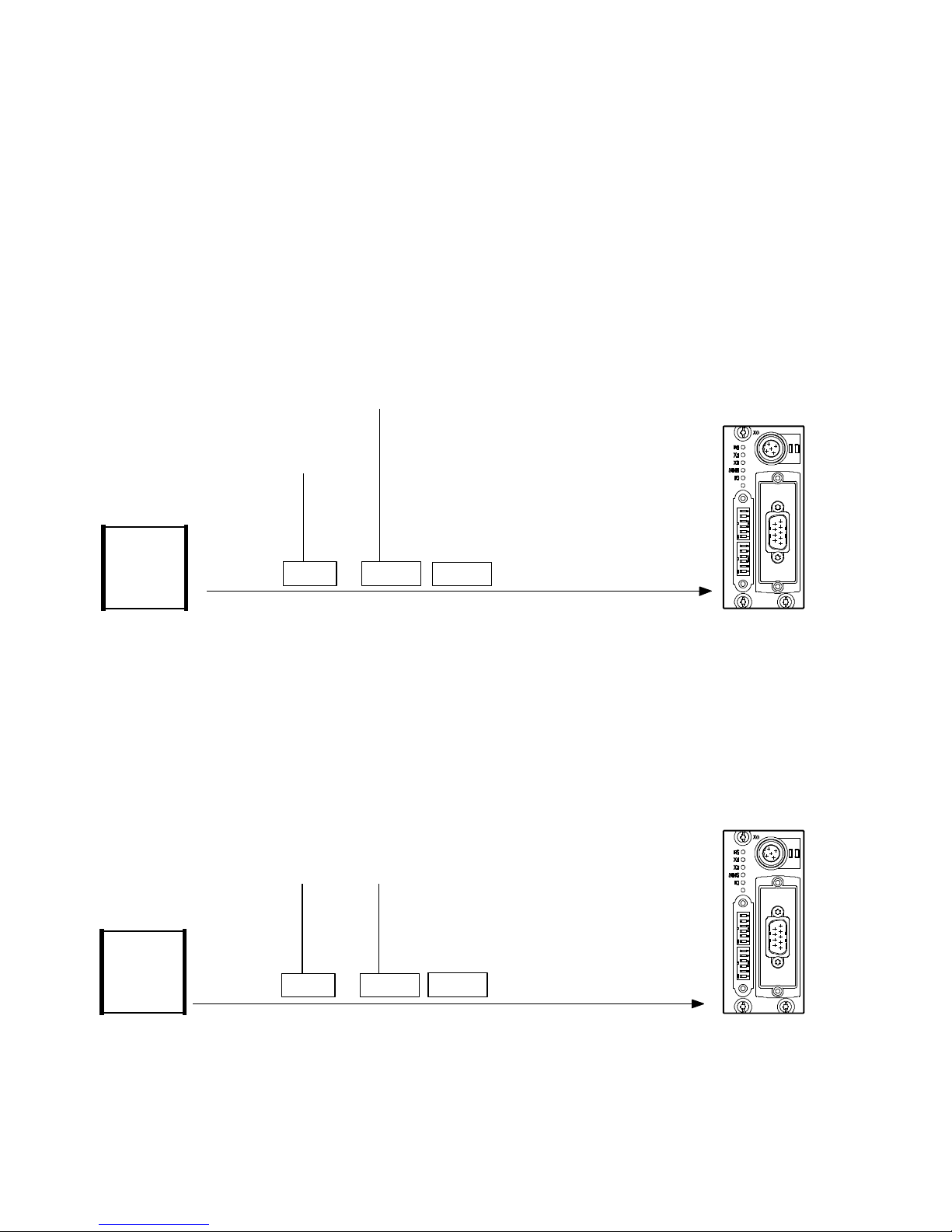
1.5.3 Examples of the communication sequence
The following examples refer to module ID = 1, i. e. the preset
station number of the bus node is “1”.
Example 1: Start CANopen network
Data
COB-ID
xx = station number
(00 = all bus slaves)
(all values in hex)
01 xx000 :
PLC/PC/IPC
Fig. 1/3: Example 1, start CANopen network
Example 2: Set output
To set outputs or valves via the bus node the receive PDO
must be sent from the master controller. In the example, only
output 0 is set, any outputs already set will be reset.
COB-ID
PLC/PC/IPC
Data
01 00201 :
xx xx
xx xx
(all values in hex)
Fig. 1/4: Example 2, set output 0 of the bus node
1-14
Festo P.BE-CTEU-CO-OP+MAINT-EN en 1101NH
Page 29
1. Commissioning
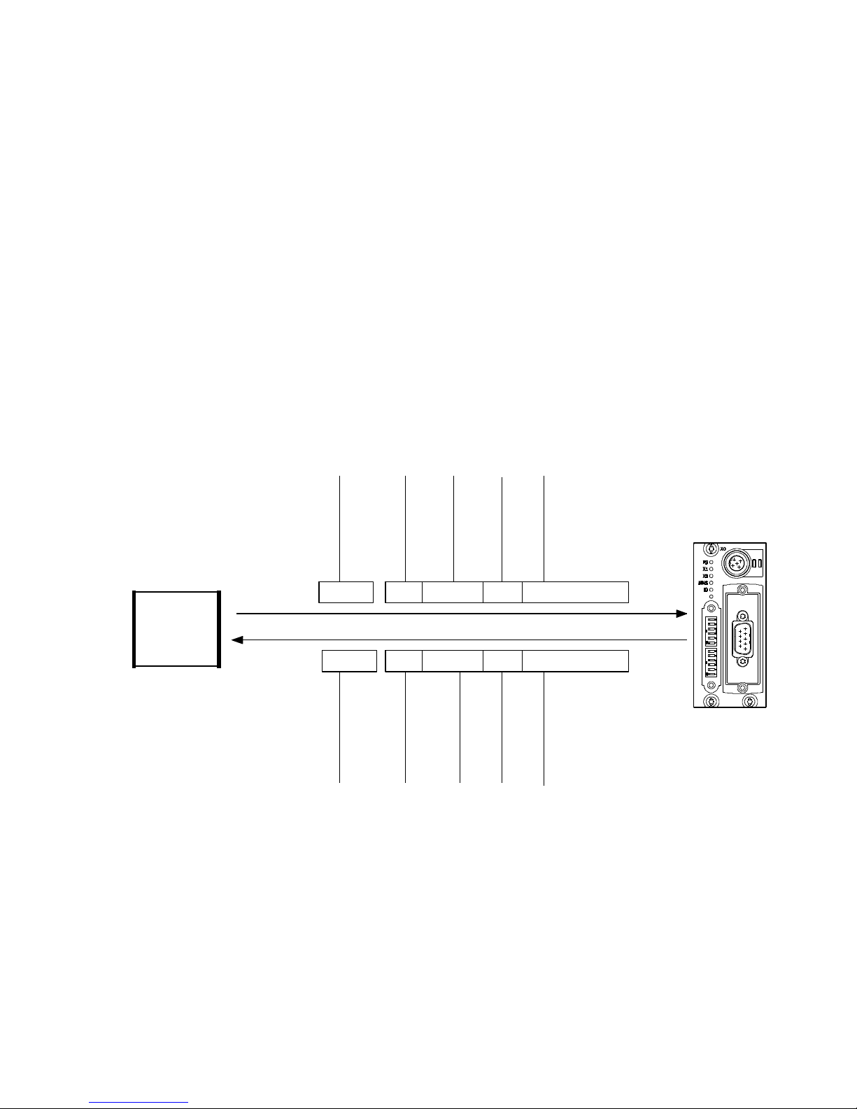
Example 3: Load objects
The following objects of the bus node can be loaded or read
via SDO transfer:
– Upload command
– Index and subindex
The bus node then sends:
– Index and subindex
– Data bytes
Index
Sub-index
4databytes
00 00 00 000000 10
91 01 30 000000 1043
Index
Sub-index
4 data bytes
(all values in hex)
PLC/PC/IPC
COB-ID
601 :
581 :
COB-ID
Initiate Domain
Upload Request
40
Initiate Domain
Upload Response
Fig. 1/5: Example 3, index 1000h, read subindex 0 (device type: device profile, device
extension)
Festo P.BE-CTEU-CO-OP+MAINT-EN en 1101NH
1-15
Page 30
1. Commissioning
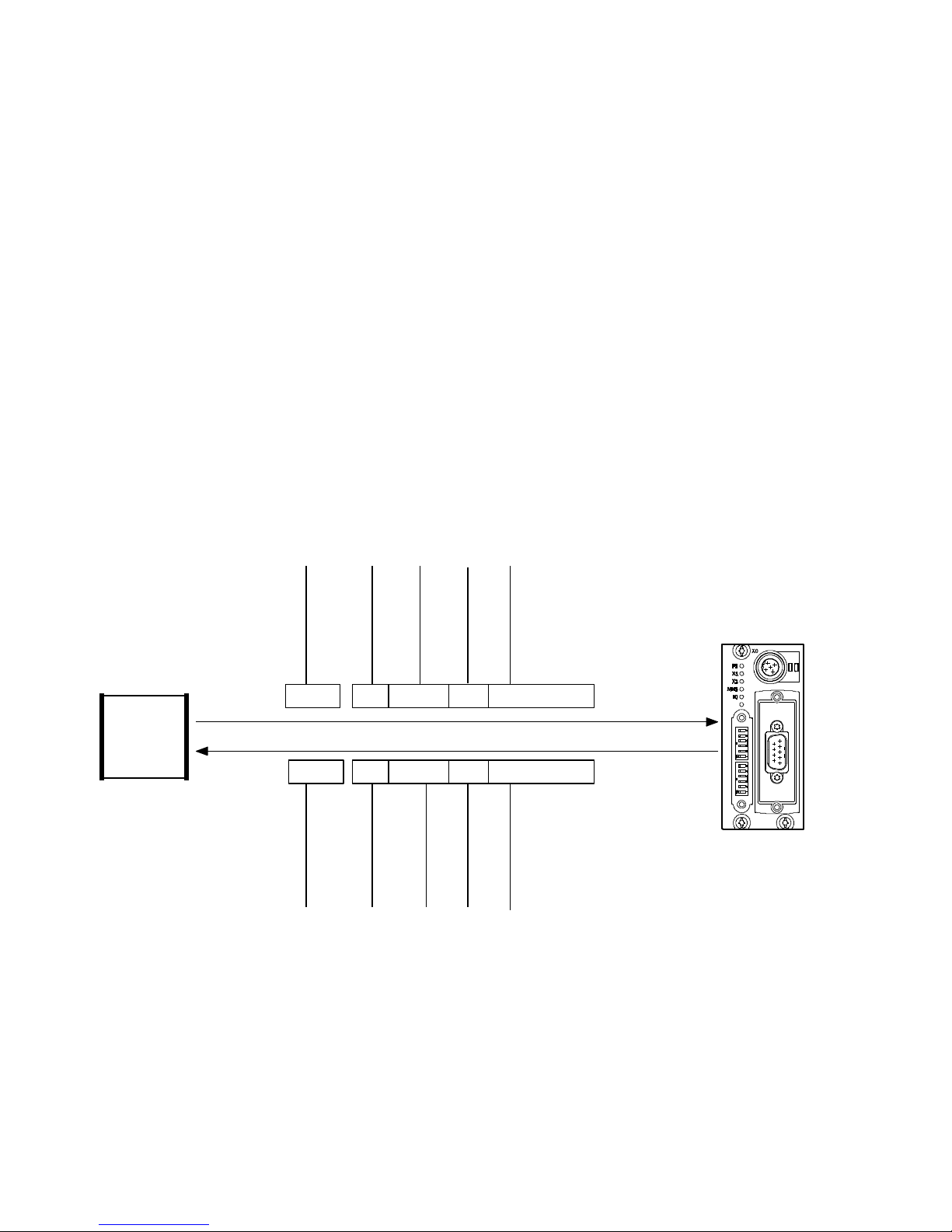
Example 4: Write objects
T o write in objects of a bus node the following information
must be read first from the bus node via SDO:
– Download command
– Index and subindex
–Value
The bus node then sends as acknowledgement:
– Index and subindex
– data bytes (not relevant)
Index
Sub-index
4 data bytes
04 7F 00 00000C 102B
00 00 00 00000C 1060
Sub-index
Index
(4 data bytes)
(all values in hex)
PLC/PC/IPC
COB-ID
601 :
581 :
COB-ID
Initiate Domain
Upload Request
Initiate Domain
Upload Response
Fig. 1/6: Example 4: Index 100CH, Subindex 0 written (Guard Time)
1-16
Festo P.BE-CTEU-CO-OP+MAINT-EN en 1101NH
Page 31
1. Commissioning
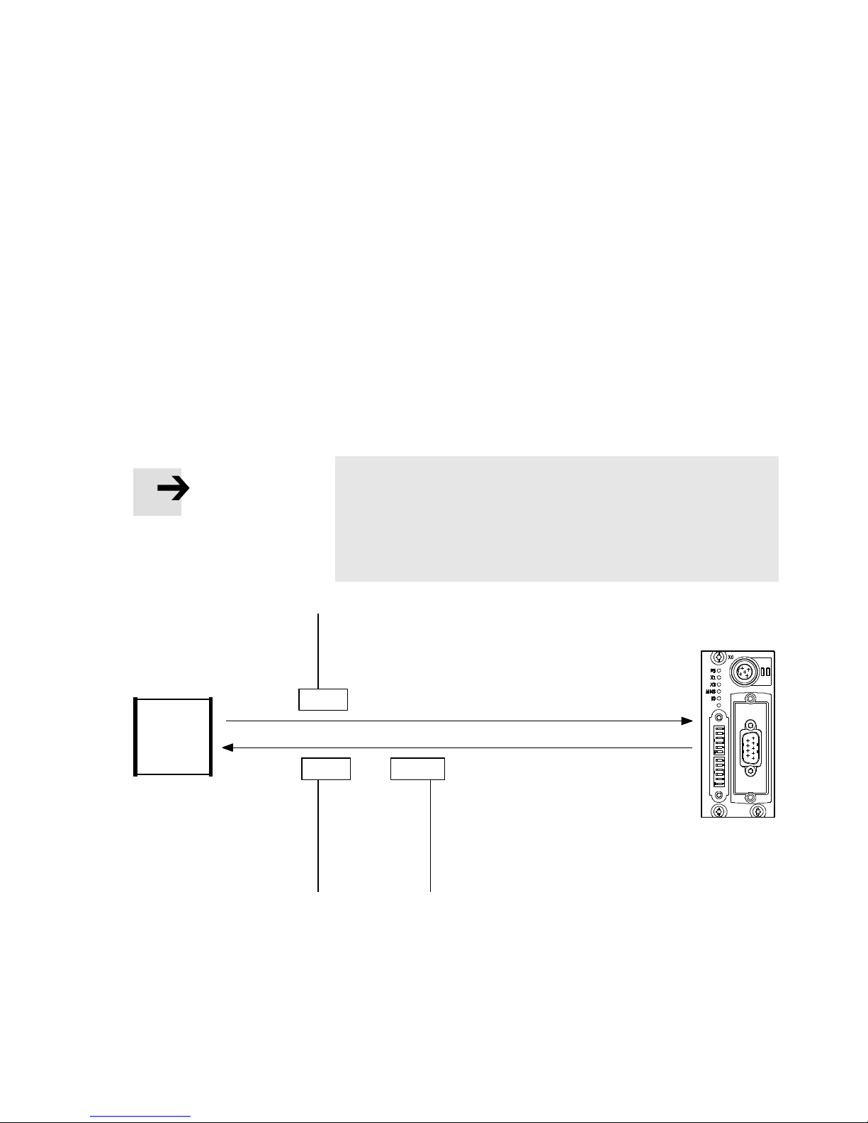
Example 5: Start “Node guarding” monitoring
Load first the indices 100C and 100D via SDO transfer (see
example 3). The “Node guarding” monitoring of the bus node
starts when the first “Node guarding” telegram is received.
This telegram must be cyclically repeated within the timeout
time:
Timeout time = guard time · life time factor
= Index 100C · index 100D
If this time is exceeded, the valves/outputs will be switched
off or they will assume the “Fail state” status.
PLC/PC/IPC
Note
The timeout monitoring in the bus node is inactive until the
first “Node guarding” telegram is received: Outputs that
have been set (e.g. switched valves) remain set even after
a loss of communication, fieldbus interruptions, et c.
COB-ID
*)
701
Node guarding response
701 :
COB-ID
05
Data
Bit 7 = toggle bit
(all values in hex)
Fig. 1/7: Example 5, start “Node guarding” monitoring (*)Remote request)
Festo P.BE-CTEU-CO-OP+MAINT-EN en 1101NH
1-17
Page 32

1. Commissioning
1.6 Switching on
1.6.1 Information concerning the switch-on behaviour of the bus node
In order to avoid connecting and addressing errors, you
should carry out commissioning in steps as follows. Observe
the following information concerning the switch-on behaviour:
• Pleasenotethatanydevicestobeconnectedmustbe
logically connected to the bus node before switching on
the CTEU bus node, otherwise it will result in an error
message and no process data will be available fo r transmission.
• Only mount the bus node to the same or an identical and
equally-configured device while maintaining the operating
voltage supply in order to avoid any malfunctions.
The configuration of connected devices is lost as soon as
the operating voltage supply of the bus node is disconnected.
• Disconnect the operating voltage from the bus node be-
fore connecting other devices, as the configuration process is only retransmitted after the bus node is switched
on again.
• Before switching it on, make sure the details regarding
the fieldbus configuration are complete and correct.
• Connect any devices to the bus node via the I-Port, as
these are only recognised by the bus node when the operating voltage is switched on.
1-18
Festo P.BE-CTEU-CO-OP+MAINT-EN en 1101NH
Page 33
1. Commissioning
1.6.2 Switching on the operating voltage
Note
Please observe the switch-on instructions in the manual for
your PLC.
Observe the following points before switching on the power
supply:
Common supply The master controller and all fieldbus stations are switched
on via a central power supply unit or a central switch.
Separate supply If the master controller and the fieldbus stations have separ-
ate power supplies, they should be switched on in the following sequence:
1. Switch on the operating voltage supply for all fieldbus
stations.
2. Switch on the operating voltage supply for the controller.
Festo P.BE-CTEU-CO-OP+MAINT-EN en 1101NH
1-19
Page 34
1. Commissioning
1.6.3 Normal operating status
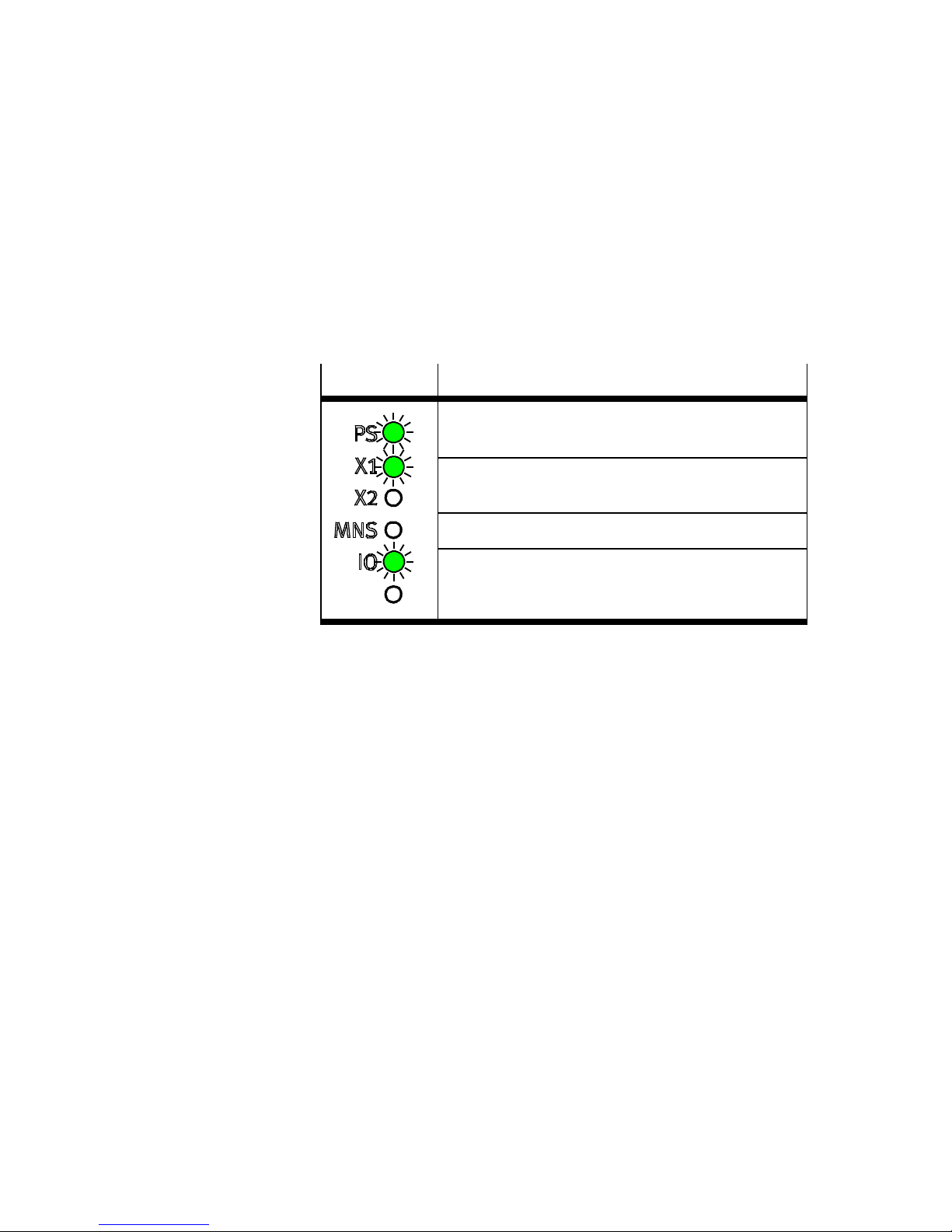
After an error-free commissioning procedure and during normal operation the operating status LEDs on the bus node
illuminate as follows:
LED display Status
PS illuminates green when the voltage supply is
established.
X1/X2 illuminates green when the device has been
connected correctly.
MNS is off during normal ope ration.
IO illuminates green as soon as commissioning of
fieldbus communication has been successful and
the bus node is controlled by the master controller.
Tab. 1/5: Operating status LEDs when switching-on
Information about diagnosing using the LED displays can be
found in section 2.2.
1-20
Festo P.BE-CTEU-CO-OP+MAINT-EN en 1101NH
Page 35
1. Commissioning
1.7 Fail state behaviour
Fail state regulates the behaviour of the bus node and the
connected devices in the event of communication errors
(see section 2.3.3).
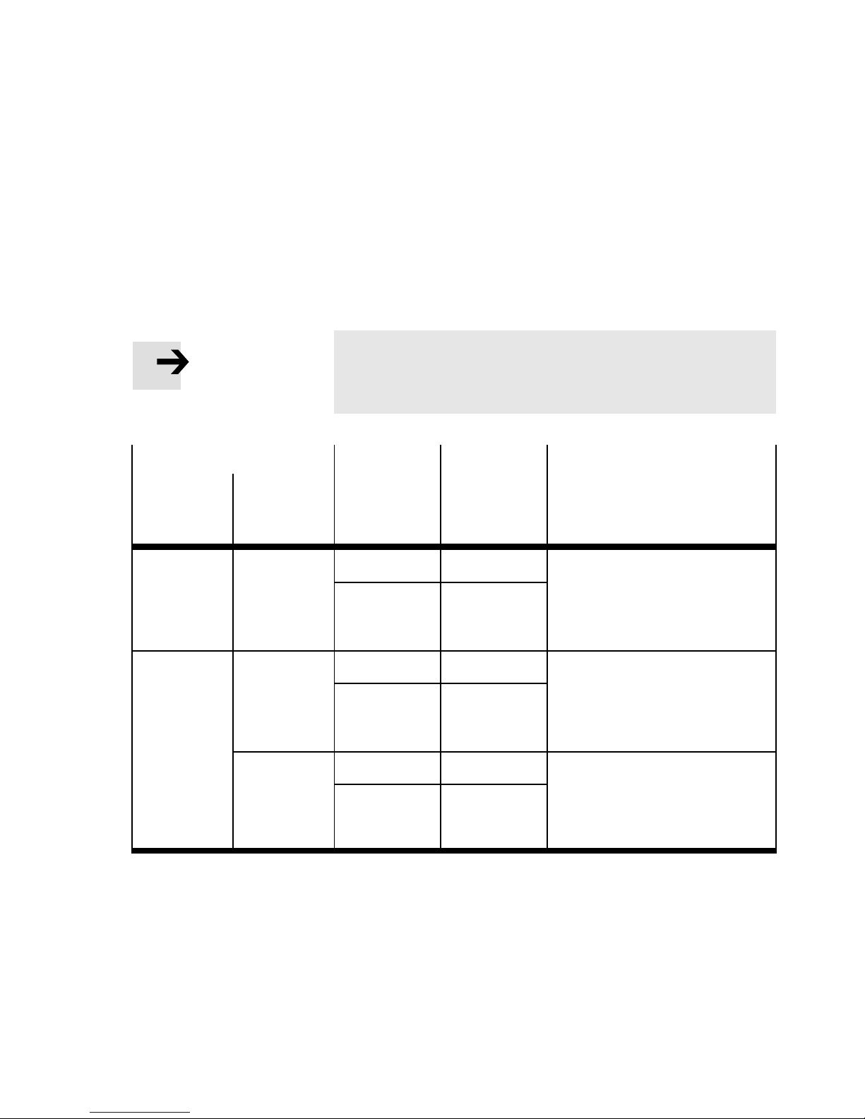
Note
AsaprerequisiteNodeguardingorHeartbeatmustbe
activated on the master controller.
Behaviour
of the
fieldbus
of the
connected
device
Ok Timeout Off are reset Master controller reports a con-
Timeout Ok Off are reset “MNS” LED on the bus node illu-
Timeout Off are reset The “X1” a nd/or “X2” LED on the
DIL switches Device: Diagnostics
Fail state
switching
position
On remain set
On remain set
On remain set
Signals
applied by
the bus node
(“Hold last
state”)
(“Hold last
state”)
(“Hold last
state”)
nection fault
The “X1” and/or “X2” LED on the
bus node illuminate red
minates red
bus node illuminate red and
“MNS” LED on the bus node illuminates red
Tab. 1/6: Constel l ati o ns of Fail state behaviour
Festo P.BE-CTEU-CO-OP+MAINT-EN en 1101NH
1-21
Page 36

1. Commissioning
1 DIL switch
settings:
Off = reset
(default)
On = Hold last
state
Fig. 1/8: DIL switches for Fail state behaviour
Furth er information relating to the DIL switches on the bus
node can be found in Part I of the product documentation
entitled “Installation and Interface manual”, which is supplied
with the bus node.
1
1-22
Festo P.BE-CTEU-CO-OP+MAINT-EN en 1101NH
Page 37

Diagnosis
Chapter 2
Diagnosis
2-1Festo P.BE-CTEU-CO-OP+MAINT-EN en 1101NH
Page 38

2. Diagnosis
Contents
2. Diagnosis 2-1.....................................................
2.1 Summary of diagnostics options 2-3...................................
2.2 Diagnostics via LED display 2-4.......................................
2.2.1 Normal operating status display 2-5...........................
2.2.2 PS-LED status display 2-5....................................
2.2.3 Status display X1-/X2-LEDs 2-6...............................
2.2.4 Status display MNS-L ED 2-7..................................
2.2.5 I/O-LED status display 2-8....................................
2.3 Diagnostics via fieldbus 2-9..........................................
2.3.1 Diagnostics via SDO 2-9.....................................
2.3.2 The Emergency Message 2-9..................................
2.3.3 Reaction to network communication faults 2-13...................
2.3.4 Node guarding 2-13..........................................
2-2
Festo P.BE-CTEU-CO-OP+MAINT-EN en 1101NH
Page 39

2. Diagnosis
2.1 Summary of diagnostics options
The following possibilities for diagnosis and error handling
are available, depending on the configuration of the bus
node:
Diagnostic
Brief description Advantages Detailed
possibility
LED display The LEDs show directly
configuration faults,
hardware faults, bus faults,
etc.
Diagnostics via
fieldbus
–DiagnosticsviaSDO
– Emergency message
T ab . 2/1: Diagnostics options
1 DIL switch
settings:
Off = no
diagnostic
messages
(default)
On = Emergency
Message is sent
description
Fast “on-the-spot”
recognition of errors
Detailed fault recognition Section 2.3
Section 2.2
1
Fig. 2/1: DIL switches for diagnostic messages
Festo P.BE-CTEU-CO-OP+MAINT-EN en 1101NH
Furth er information relating to the DIL switches on the bus
node can be found in Part I of the product documentation
entitled “Installation and Interface manual”, which is supplied
with the bus node.
2-3
Page 40

2. Diagnosis
2.2 Diagnostics via LED display
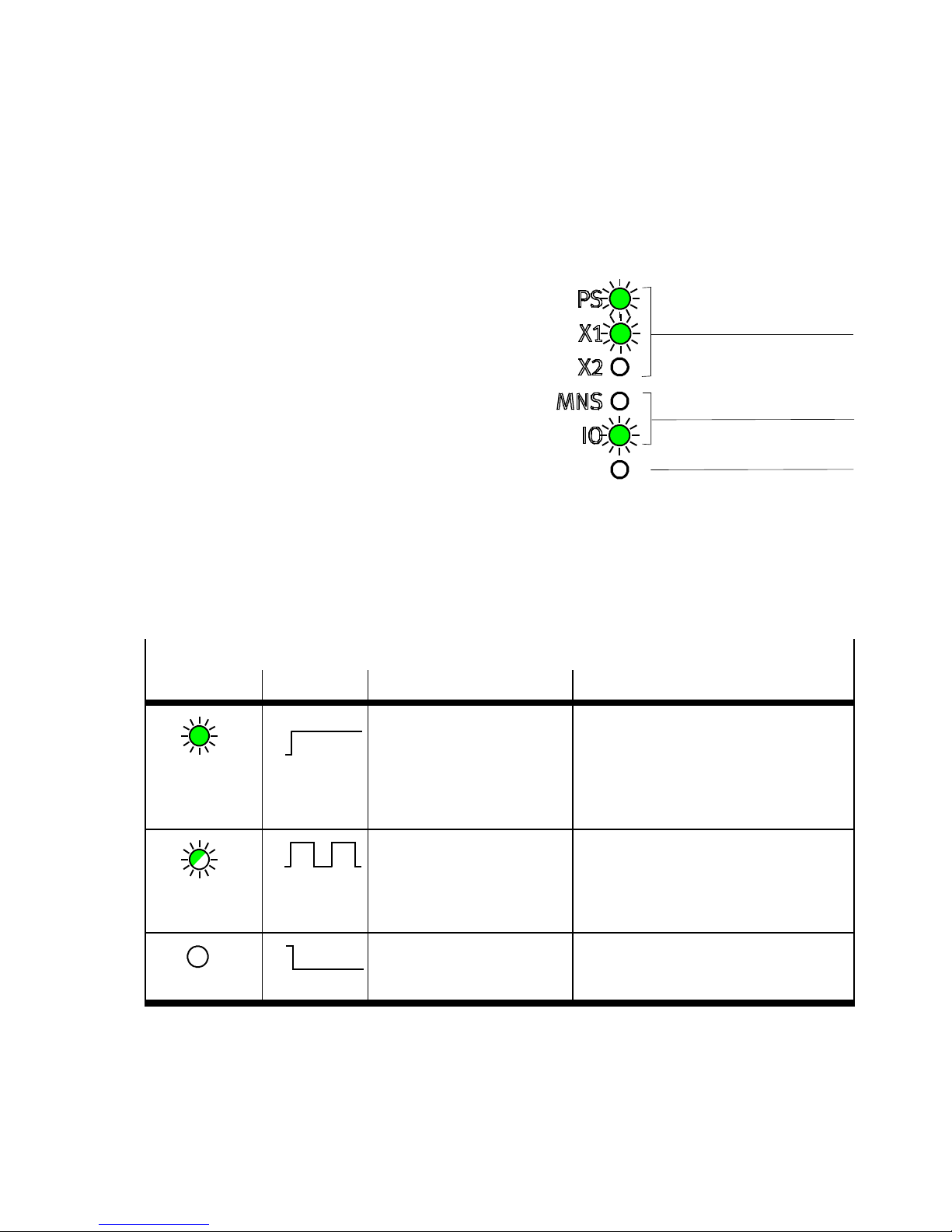
LEDs are located on the bus node for diagnosing the bus
node and any connected devices (see Fig. 2/2).
The LEDs can assume the following states (sometimes in
different colours):
illuminates flashes off
2-4
Festo P.BE-CTEU-CO-OP+MAINT-EN en 1101NH
Page 41
2. Diagnosis
2.2.1 Normal operating status display
CTEU-specific
1
LEDs
2 Fieldbus-specific
LEDs
1
3 Reserved
Fig. 2/2: LEDs on the bus node
2.2.2 PS-LED status display
PS (power system) – power sensor/logic supply
LED Procedure Status Meaning/error elimination
LED
illuminates
green
LED flashes
green
ON
OFF
ON
OFF
Normal operating status:
Operating voltages are in
thepermissiblerange.
Undervoltage for the signal
or load voltage supply or
short circuit of the bus
node's I-Port
–
• Eliminate short circuit on the bus
node
• Eliminate undervoltage on the con-
nected device
2
3
ON
OFF
LED is off
Tab. 2/2: Status displays of the device-specific “PS” LED
Festo P.BE-CTEU-CO-OP+MAINT-EN en 1101NH
Signal voltage is not
present.
Check signal voltage supply
(pin 1 and 3)
2-5
Page 42
2. Diagnosis
2.2.3 Status display X1-/X2-LEDs
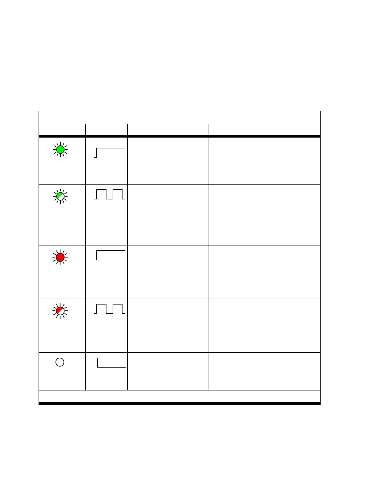
X1 or X2
1)
– Internal communication between the bus node and device 1 or 2
LED Procedure Status Meaning/error elimination
LED
illuminates
green
LED flashes
green
ON
OFF
ON
OFF
– Normal operating status
– Device is connected cor-
rectly to the bus node.
– Load voltage applied.
– There is no error.
– Diagnostics is running
and/or diagnostic data
is being transferred.
– Undervoltage of the ad-
ditional power supply.
–
• Device diagnostics can be read via
fieldbus communication
(if activ ated via DIL switches on the
bus node)
• Eliminate undervoltage
– Connection between bus
node and device ok
ON
OFF
LED
illuminates red
– Device is connected to
the bus node but com-
munication is disrupted.
– An incorrect device has
been c onnected after
• Check fieldbus: cables, plug
connectors, signal transmission
(error counter overrun)
• Restart the bus node (by switching
the power off -> on)
commissioning.
1)
ON
OFF
LED flashes
red
ON
OFF
LED is off
1)
Separate accessory with two interfaces for connecting another device is required.
Tab. 2/3: Status displays of the device-specific “X1” LED if device 1 is connected and
“X2” if device 2 is connected.
2-6
– Incorrect device connec-
ted (device detected
thatisnotI-Portcom-
patible)
– In addition with LED X1:
Error in the bus module
– Connection is being es-
tablished.
– No device is connected
to the bus node
• Use an I-Port compatible device
(e. g. suitable valve terminal) from
Festo
• If no device is connected, X1 and X2
flash red
–
Festo P.BE-CTEU-CO-OP+MAINT-EN en 1101NH
Page 43

2. Diagnosis
2.2.4 St at us display MNS-LED
MNS (network status)
LED Procedure Status Meaning/error elimination
ON
OFF
LED
illuminates red
– Fieldbus communication is
not available or has failed.
– Voltage supply to / via the
fieldbus has failed.
• Fieldbus is offline
• CAN error
• CAN short circuit
• Check connection to network
• Check the setting of the DIL
switches
• Check the voltage supply to /
via the fieldbus
ON
OFF
Communication error - fieldbus
communication is defective
• Timeout ascertained
• Check connection to network
LED flashes
red
ON
OFF
LED is off
Normal operating status/no
communicationerror on the
fieldbus
• Diagnosis is possible
• Access to connected devices is
possible through PDO/SDO
access
Tab. 2/4: Status displays of the fieldbus-specific “MNS” LED
Festo P.BE-CTEU-CO-OP+MAINT-EN en 1101NH
2-7
Page 44
2. Diagnosis
2.2.5 I/O-LED status display
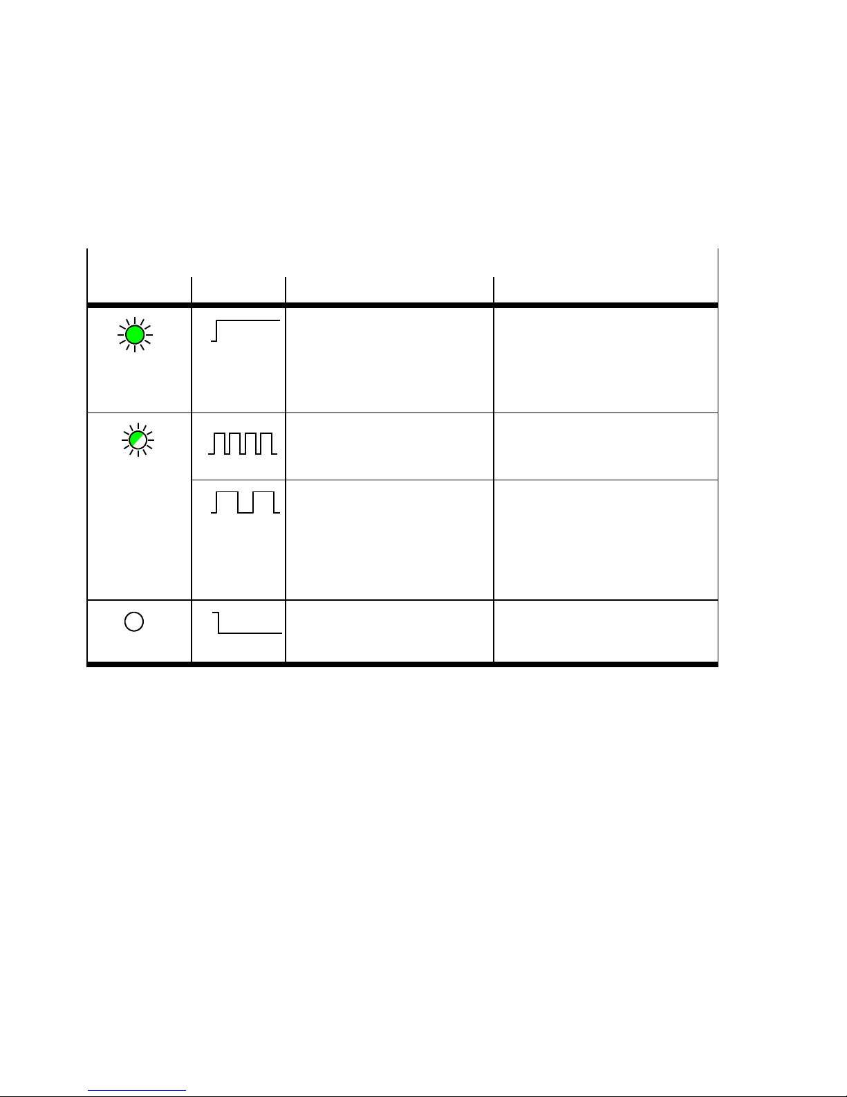
I/O (I/O status)
LED Procedure Status Meaning/error elimination
ON
OFF
LED
– Bus node is in operational
mode.
Normal operating status/ready
status when the bus node is controlled by the master controller .
illuminates
green
ON
OFF
– Bus node is in pre-operational
mode.
Ready status is in preparation.
LED flashes
ON
OFF
– Fieldbus communication is
interrup ted and automatically
Ready status has been stopped.
restored.
– Amend the incorrect station
number on the bus node or
the controller
ON
OFF
LED is off
– No commissioning of the
fieldbus
– No fieldbus connected
• No device connected
• Station number (Node ID) = 0
Tab. 2/5: Status displays of the fieldbus-specific “I/O” LED
is set
2-8
Festo P.BE-CTEU-CO-OP+MAINT-EN en 1101NH
Page 45
2. Diagnosis
2.3 Diagnostics via fieldbus
2.3.1 Diagnostics via SDO
The master controller can query diagnostic information via
SDO access on the bus node. The corresponding SDOs can be
found in the object directory in section A.2.
2.3.2 The Emergency Message
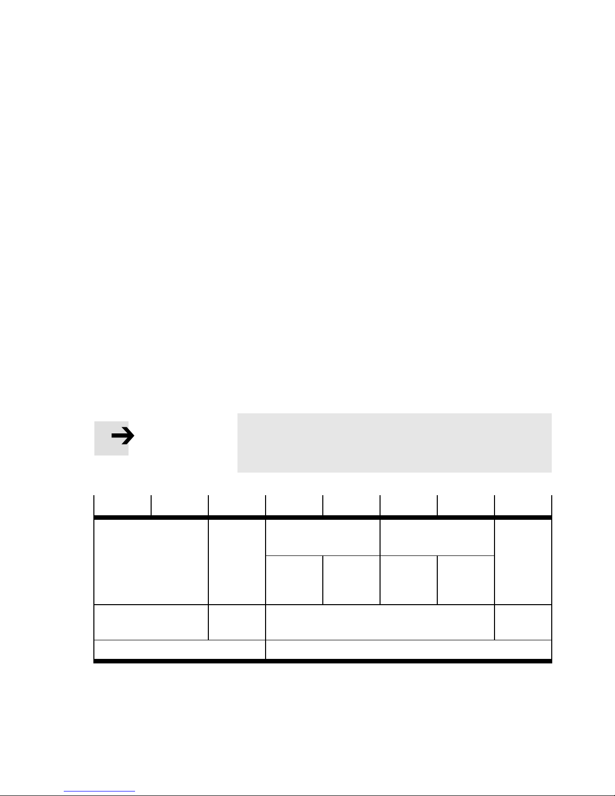
If an error occurs the bus node can send an emergency
message with a defined structure (see Tab. 2/6) when the
“diagnostics” DIL switch is activated (see section 2.1). The
following sections describe the components of the emergency
message and the error causes (see Tab . 2/9).
Note
AsaprerequisiteNodeguardingorHeartbeatmustbe
activated on the master controller.
Byte 0
Error code Error Re-
CANopen standard Manufacturer specific error field
Byte 1 Byte 2 Byte 3 Byte 4 Byte 5 Byte 6 Byte 7
Device 1 Device 2 Reserved
gister
Diagnostics
byte 1
Obj. 1001 Obj. 1002
Manufacturer status register
Diagnostics
byte 2
Diagnostics
byte 1
T ab . 2/6: Composition of the Emergency Message Object
Diagnostics
byte 2
Festo P.BE-CTEU-CO-OP+MAINT-EN en 1101NH
2-9
Page 46
2. Diagnosis
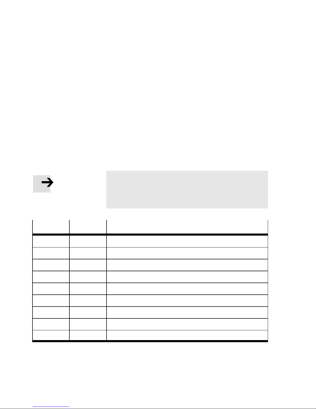
The p re-defined error field as fault memory
If the Emergency Message is transmitted, a compressed form
of the fault information will be saved parallel in the Pre-Defined
Error Field (Index 1003).
Device1+2DIAG,ErrorCode
The Pre-defined Error Field serves as fault memory for the last
faults ascertained.
Error Codes
Note
If several Emergency Messages from Tab. 2/7 are present,
only the most recently reported is transmitted to the master controller.
Byte 0
00 00 No error
20 22 Short circuit diagnostics
20 23 Short circuit at outputs
20 31 Operating voltage too low
20 33 Load voltage too low
00 50 Hardware fault
30 81 Node guarding or Heartbeat error
00 FF Configuration error
Byte 1 E xplanation
FF FF Diagnostic message from I-Port telegram
T ab . 2/7: Bus node Error Codes (as per DS401)
2-10
Festo P.BE-CTEU-CO-OP+MAINT-EN en 1101NH
Page 47
2. Diagnosis
Error register
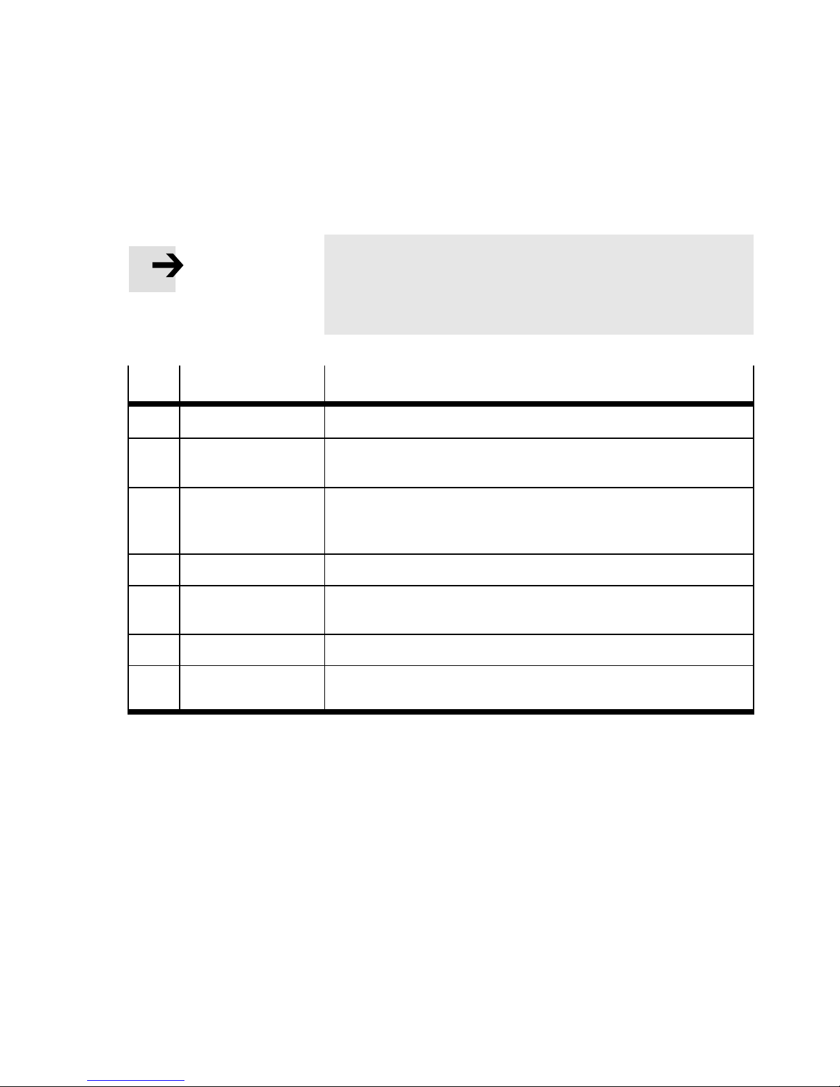
Note
One or more Error Codes for each Emergency Message can
be transferred to the master controller with the help of the
Emergency Messages from Tab. 2/8.
Bit
5…6 – –
Meaning Explanation
0 Generic error Bit is set for each error
1 Current – Short circuit/overload of sensor supply
– Short circuit/overload of connected devices
2 Voltage – Operating voltage too low
– Load voltage too low
– Load voltage not applied
3 – –
4 Communication
Error
7 Manufacturer
specific
– Node guarding, Heartbeat, CANopen error
–Wirefracture
– other errors
T ab . 2/8: Error Register (Object 1001 with bit assignment as per DS301/401)
Festo P.BE-CTEU-CO-OP+MAINT-EN en 1101NH
Manufacturer Status Register
Error causes of the devices connected to the bus node are
transmitted via bytes 3 and 4 or 5 and 6 of the Emergency
Message (Manufacturer Status Register, Object 1002).
Transmittable error causes
The following error causes are reported to the master controller by the bus node (Tab. 2/9):
2-11
Page 48

2. Diagnosis
Error causes Device
on the
bus no de
No error X 00 00 00 00 00 00 00 res.
Device short circuit I-Port 1 20 22 83 10 77 00 00
Device short circuit I-Port 2 20 22 83 00 00 10 77
I-Port Pin4 short circuit I-Port 1 20 23 83 A0 8C 00 00
I-Port Pin 4 short circuit I-Port 2 20 23 83 00 00 A0 8C
No load voltage or
insufficient load
voltage
No load voltage or
insufficient load
voltage
No operating voltage
or insufficient
operating voltage
I-Port 1 20 33 85 12 51 00 00
I-Port 2 20 33 85 00 00 12 51
X 20 31 85 00 00 00 00
Byte
(Structure as per Tab. 2/6)
0 1 2 3 4 5 6 7
Hardware error X 00 50 01 00 10 00 00
Hardware error X 00 50 01 00 00 00 10
Configuration error X 00 FF 01 00 00 00 00
Configuration error I-Port 1 00 FF 01 00 10 00 00
Configuration error I-Port 2 00 FF 01 00 00 00 10
Other I-Port
diagnostic message
Other I-Port
diagnostic message
Node guarding or
Heartbeat error
X = Error is present on the bus node itself or is not clearly assigned to a device that is conn ected to the
bus node via the I-Port interface.
I-Port 1 FF FF 81 Event
C. Low
I-Port 2 FF FF 81 00 00 Event
X 30 81 11 00 00 00 00
Event
C.High
00 00
Event
C. Low
C.High
Tab. 2/9: Transmittable error causes via Emergency Message
2-12
Festo P.BE-CTEU-CO-OP+MAINT-EN en 1101NH
Page 49

2. Diagnosis
2.3.3 Reaction to network communication faults
Note
Please observe the following if the outputs are reset in the
event of a PLC stop or field bus interruption or
malfunction:
– Single-solenoid valves move to the basic position.
– Double-solenoid valves remain in the current position.
– Mid-position valves mo ve to the mid position (depending
on the valve type: pressurised, exhausted or blocked).
2.3.4 Node guarding
You can parameterise the behaviour of connected devices in
the event of a fault. All valves/outputs of connected devices
are reset as standard when the following faults and operating
states occur as soon as Node guarding or Heartbeat are activated via the configuratio n:
– Communication error (Node guardi ng, Heartbeat)
– Transitio n from operational to pre-operatio nal or stopped
The behaviour of connected devices in the event of communication errors can be changed using the corresponding DI L
switches (see section 1.7).
In order for CANopen to recognise a fieldbus failure Node
guarding must be activated on the master controller (default:
switched off ).
Festo P.BE-CTEU-CO-OP+MAINT-EN en 1101NH
Inthecaseofactuatorsitisadvisabletomonitorthemaster
controller for failure in order to provide an appropriate emergency shutdown strategy .
2-13
Page 50

2. Diagnosis
Then the master controller is monitored based on monitoring
of activation with the configured monitoring time (see DS 301).
When monitoring is activated, the co nfi gured emergency stop
response (Fault reaction option code object 605Eh, PNU
1021) is executed and the drive is stopped.
Select the “Guard Time” with reference to the dynamics of the
system.
Refer to your master controller documentation for details on
how to activate Node guarding.
2-14
Festo P.BE-CTEU-CO-OP+MAINT-EN en 1101NH
Page 51

Error treatment
Chapter 3
Error treatment
3-1Festo P.BE-CTEU-CO-OP+MAINT-EN en 1101NH
Page 52

3. Error treatment
Contents
3. Error treatment 3-1................................................
3.1 Fault finding and error elimination 3-3.................................
3.1.1 Check the installation 3-3....................................
3.1.2 Check the power supply 3-4..................................
3.1.3 Restart communication between the bus node and the device 3-5...
3.1.4 Check fieldbus communication 3-5.............................
3.1.5 Check the CANopen configuration 3-6..........................
3.1.6 Read out diagnostic messages via CANopen 3-7.................
3-2
Festo P.BE-CTEU-CO-OP+MAINT-EN en 1101NH
Page 53

3. Error treatment
3.1 Fault finding and error elimination
This section is meant as a checklist to help you inspect your
installation and commissioning steps if an error occurs. Y ou
will find important information and references here to the
respective sections of the two-part product documentation
for the bus node.
Exclude potential sources of error by working through the
following sections completely and in the specified order.
3.1.1 Check the installation
• Check the correct installation of the bus node on the
device or the CAPC… electric sub-base and the correct
earthing of all of the components involved.
• Make sure that all of the necessary cabl es are fitted
correctly.
Information relating to installing the bus node can be found in
Part I of the product documentation entitled “Installation and
Interface manual”, which is supplied with the bus node.
Information for mounting the bus node on the CAPC… electri c
sub-base can be found in the assembly instructions supplied
with the electric sub-base.
Festo P.BE-CTEU-CO-OP+MAINT-EN en 1101NH
3-3
Page 54

3. Error treatment
3.1.2 Check the power supply
Warning
• Use only PELV circuits as per IEC/EN 60204-1 for the
electric power supply (protective extra-low voltage,
PELV).
Also observe the general requirements for PELV circuits
in accordance with IEC/EN 60204-1.
• Use only power sources that guarantee reliable
electrical isolation of the operating voltage as per
IEC/EN 60204-1.
• Check to make sure both power supplies for the operat-
ing and load voltage are connected.
The devices connected to the bus node are powered
exclusively via the load voltage connection.
• Check the pin assignment of self-assembled cables.
Information relating to installing the bus node can be found in
Part I of the product documentation entitled “Installation and
Interface manual”, which is supplied with the bus node.
Normal status LED PS-LED illuminates green and the X1 and/or X2 LED illuminate
green.
Error status 1 The operating voltage supply for the bus node exhibits under-
voltage:
– PS-LED flashes green
3-4
Festo P.BE-CTEU-CO-OP+MAINT-EN en 1101NH
Page 55

3. Error treatment
Error status 2 The load voltage supply for the connected device(s) is miss-
ing or exhibits undervoltage:
– PS-LED flashes green and
– X1 and/or X2-LED flash green
Prerequisite: That connected device(s) must support this
diagnostic function (see device description).
3.1.3 Restart communication between the bus node and the device
Problem description: X1 and X2 flash red simultaneously despite checking the
mechanical connection between the bus node and the device
(disassembly -> assembly)
Remedy: Proceed as follow s:
1. Disconnect the operating voltage.
2. Check the assembly and/or re-establish the cable connection between the bus node and connected devices.
3. Switch voltage on again.
X1 and/or illuminate or flash green.
3.1.4 Check fieldbus communication
• Compare the desired baud rate with the baud rate set on
the bus node (DIL switch setting).
• Compare the desired Node ID with the Node ID set on the
bus node (DIL switch setting).
Information relating to installing the bus node can be found in
Part I of the product documentation entitled “Installation and
Interface manual”, which is supplied with the bus node.
Festo P.BE-CTEU-CO-OP+MAINT-EN en 1101NH
3-5
Page 56

3. Error treatment
• Compare your selected cable lengths with the technical
data in the appendix and the recommendations of the
CiA specification.
• Check the installation of the terminating resistors at both
ends of the fieldbus.
• Te st the fieldbus communicati on using the object directory
(see section A.2).
Normal status LED MNS-L ED is off and I/O-LED illuminates green (in operational
mode) or is off (in the event of defective fieldbus communication).
3.1.5 Check the CANopen configuration
Problem description: Process data is faulty.
Remedy: Proceed as follow s:
1. Check whether the mapping element conforms to the settings of the master controller (see section A.2).
2. Check whether the status of the bus node, e. g. operational mode, complies with the settings of the master controller (see section 2.2.5).
Problem description: Outputs do not switch to the desired state in the event of
fieldbus communication malfunctions.
Remedy: Proceed as follow s:
1. Check whether Node guarding or Heartbeat is activated
on the master controller.
This ensures that the bus node can detect mal functions in
fieldbus communication and that the outputs are set to a
defined state after fieldbus communication is restored.
2. Check whether Fail State is activated on the bus node
3-6
(DIL switch position).
Fail State off: the outputs are set to “0” after fieldbus
communication is restored.
Festo P.BE-CTEU-CO-OP+MAINT-EN en 1101NH
Page 57

3. Error treatment
Fail State on: after fieldbus communication is restored the
outputs resume the status assumed before the failure
(“hold last state”).
3.1.6 Read out diagnostic messages via CANopen
The devices connected to the bus nodes can offer advanced
diagnostic options, which extend beyond the LED displays, if
LED X1 and/or X2 flashes green.
Option 1 Proceed as follows:
1. Activate Node guarding or Heartbeat on the master controller.
2. Wait for the display of the Emergency Messages
(see Tab. 3/10) on the master controller.
Error causes
Device
Byte
on the
No load voltage or
insufficient load
voltage
No load voltage or
insufficient load
voltage
bus node
I-Port 1 20 33 85 12 51 00 00 res.
I-Port 2 20 33 85 00 00 12 51
0 1 2 3 4 5 6 7
T ab . 3/10: Extract from the Emer gency Message table (see section 2.3.2)
Option 2 Proceed as follows:
• Retrie ve the SDO telegrams manually from the bus node
and evaluate them (see object directory in sectio n A.2)
Festo P.BE-CTEU-CO-OP+MAINT-EN en 1101NH
3-7
Page 58

3. Error treatment
3-8
Festo P.BE-CTEU-CO-OP+MAINT-EN en 1101NH
Page 59

Technical appendix
Appendix A
Technical appendix
A-1Festo P.BE-CTEU-CO-OP+MAINT-E N en 1101NH
Page 60

A. Technical appendix
Contents
A. Technical appendix A-1.............................................
A.1 Technical data A-3..................................................
A.2 Object directories A-6...............................................
A-2
Festo P.BE-CTEU-CO-OP+MAINT-EN en 1101NH
Page 61

A. Technical appendix
A.1 Technical data
General
Temper ature range
–Operation
– Storage/transport
Relative air humidity as per IEC 60770 93 % at 40 °C
-5 … +50 °C
-20…+70°C
Protection class as per EN 60529, bus node
fitted completely, plug connector inserted or
IP65/671)with appropriate cable from Festo
accessories
provided with protective cap
Protection against electric shock
(protection against direct and indirect contact as
through PELV power supply unit
(Protected Extra Low Voltage)
per EN 60204-1/IEC 204)
Electromagnetic compatibility (EMC)
– Emitted interference
– Resistance to interference
Vibration and shock
2)
See declaration of conformity
www.festo.com
Severity level (SL) for assembly on ...
tested as per DIN/IEC 68/EN 60068
–Vibration(part2-6)
– Shock ( par t 2 - 27)
– Continuous shock (part 2 - 29)
Wall: SL 2, H-rail: SL 1
Wall: SL 2, H-rail: SL 1
Wall and H-rail: SL 1
Dimensions
–Width
–Length
–Height
40 mm
91 mm
50 mm
Wei ght (bus no d e without cable and substructure) 90 g
1)
Please note that connected devices may only satisfy a lower protection class, a smaller temperat-
ure range, etc.
2)
The bus node is intended for industrial usage. In residential areas, interference suppression meas-
ures might have to be taken.
Festo P.BE-CTEU-CO-OP+MAINT-EN en 1101NH
A-3
Page 62

A. Technical appendix
General
Materials
–Housing
– Fibre-optic, cover DIL switch
– Threaded sleeve M12
– Threaded bush M3
– Seals
–Screws
RoHS-compliant
PA, re inforc ed
PC
Brass, electro nickel-plated
Brass
NBR
Galvanized steel
Corrosion protection CRC 2
Voltage supply
Operating voltage
– Nominal value
– Tolerance
Load voltage1)of connected devices
–Range
Current supply
– Power rating for operating and load voltage
(residual current)
– Intrinsic current consumption of the bus node
(at 24 V DC)
– Current consumption (at 24 V DC) of the bus
node with operation of a connected device
– Current consumption (at 24 V DC) of the bus
node with operation of one/two connected
devices via electric sub-base CAPC-…
1)
24 V DC
18 … 30 V DC
18 … 30 V DC
Max. 4 A
Max. 65 mA
Max. 120 mA
Max. 175 mA
2)
Galvanic is olation Bus interface
1)
External fuse required
2)
Dependent on the connected device (e. g. valve terminal)
A-4
Festo P.BE-CTEU-CO-OP+MAINT-EN en 1101NH
Page 63
A. Technical appendix
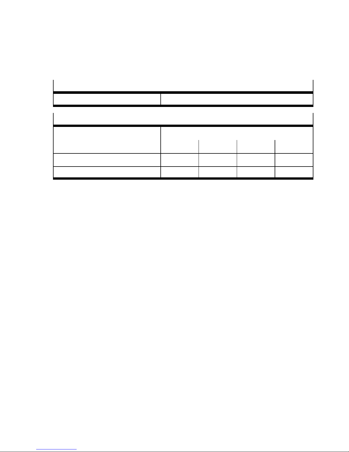
I-port interface signal transmission
– Internal cycle time 1msper1byteofuserdata
CANopen signal transmission
Max. cable lengths Baud rate
125 kbps 250 kbps 500 kbps 1 000 kbps
– Fieldbus cable (“trunk cables”) 500 m 250 m 100 m 40 m
– Branch line cable (“drop cables”) 3,75 m 2,00 m 0,75 m 0,3 m
Festo P.BE-CTEU-CO-OP+MAINT-EN en 1101NH
A-5
Page 64
A. Technical appendix
A.2 Object directories
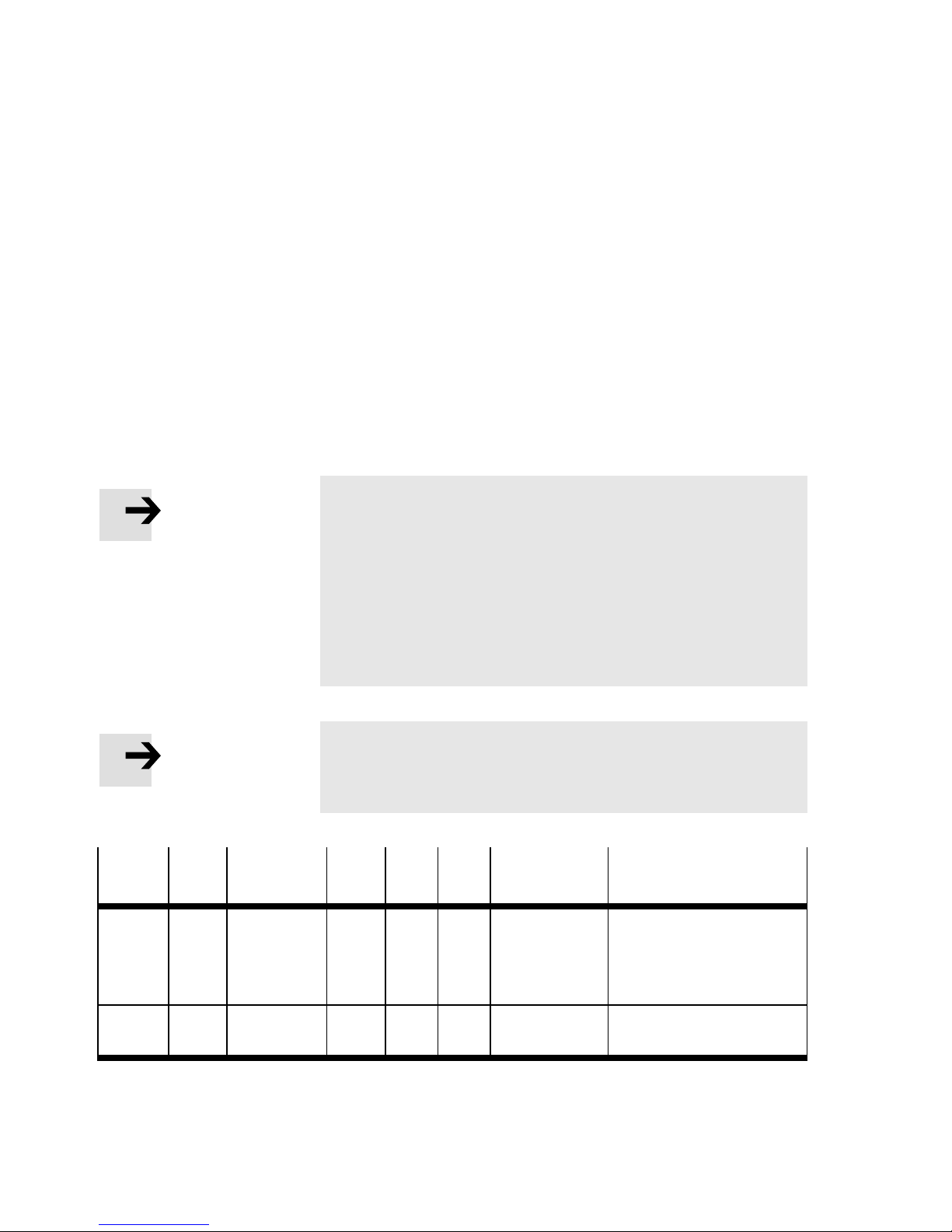
The following tables show the objects of the communication
part (values and examples with node ID = 1). The following
abbreviations mean:
U= unsigned
ro = read only
rw = read/write
Map = mapping possible
Attr. = attribute
Note
For mapping the rules as per CiA DS301 apply: Mapping
entries are only possible if the number of parameters has
previously been set to zero.
(Example: index 1A00, subindex 3 … 8:
Set subindex 0 to “0”).
After entering the mapping values set the number of parameters to the appropriate value again.
Note
Note that basic settings can only be changed via DIL
switches.
Index
(hex)
1000 0 Device type U32 ro – 00030191
1001 0 Error re-
Subindex
Designation
gister
Type Attr. Map. Values
(hex)
(fixed)
U8 ro – Nn
Explanation
01 91 = device profile
DS401
3 = Digital inputs and
digital outputs
A-6
Festo P.BE-CTEU-CO-OP+MAINT-EN en 1101NH
Page 65

A. Technical appendix
Index
(hex)
1002 0 Manufac-
1005 0 COB-ID
1008 0 Manufac-
1009 0 Manufac-
100A 0 Manufac-
Subindex
tion
turer Status
Register
SYNC
Message
turer Device
Name
turer Hardware Version
turer Software Version
Map.Attr.TypeDesigna-
ExplanationValues
(hex)
U32 ro Yes 00 00 00 00 -First2byteswithdia-
gnostics-telegram from
Device 1
- Last 2 bytes with diagnostics-telegram from
Device 2
U32 rw – 80 00 00 80 Default SYNC message
COB-ID 80
Str. ro – “CTEU-CO” Bus node designation
Str. ro – “r03” (ex-
ample)
Str. ro – “r03” (ex-
ample)
As 1018.3
As 1018.3
h
100C 0 Guard Time U16 rw – 00 00 Timeout monitoring [ms]
100D 0 Life Time
Factor
1014 0 COB-ID
Emergency
Message
1015 0 Inhibit Time
Emergency
Message
Festo P.BE-CTEU-CO-OP+MAINT-EN en 1101NH
U8 rw – 00 Timeout monitoring
(Guard time x life time
factor = complete node
guarding time)
U32 rw – 00 00 00 80 Default emergency object
COB-ID 80
U16 rw – 00 00 Transmit Blo cking Time
Emergency Message
[100µs]
+nodeID
h
A-7
Page 66

A. Technical appendix
Index
(hex)
1016 0 Consumer
1017 0 Producer
1018 0 Identity
Subindex
1 U32 rw 00 00 00 00 Heartbeat ID and
2
3
1 Vendor I D U32 00 00 00 1D Vendor ID (from CiA)
2 Product
tion
Heartbeat
Time 0 … 3
Heartbeat
Time
Object
code
Map.Attr.TypeDesigna-
ExplanationValues
(hex)
U8 ro – 03 Number of entries/
Heartbeat ID &Time [ms]
Heartbe at Time [ms]
U16 rw – 00 00 Heartbeat Time [ms]
COB-ID = Nodeguard ID
Status (pre-ope rational,
operational, stopped)
U8 ro – 04 Number of entries
570038 Product code
3 Revision
number
4 Serial
number
1200 0 Server SDO
parameter
1 COB_ID
Client
}
Server (rx)
2 COB_ID
Server
Client (tx)
}
“r03” (example)
xx xx xx xx Va lue from production
U8 ro – 02 Number of entries
U32 600 + Node ID Default COB-ID + Node ID
580 + Node ID Default COB-ID + Node ID
CANopen Revision
process
A-8
Festo P.BE-CTEU-CO-OP+MAINT-EN en 1101NH
Page 67

A. Technical appendix
Index
(hex)
1400 0 Receive
1401 0 Receive
Subindex
1 COB-ID U32 rw 200 + Node ID Default COB-ID of the
2 Transm is-
3 Inhibit Time U16 0000
5 Event Timer 0
1 COB-ID U32 rw 300 + Node ID Default COB-ID of the
tion
PDO Communication
Parameter 0
sion Type
PDO Communication
Parameter 1
Map.Attr.TypeDesigna-
ExplanationValues
(hex)
U8 ro – 05 Output PDO 0
Communication
Parameter
outputs
U8 FF
U8 ro – 05 Output PDO 1
Communication
Parameter
outputs
2 Transm is-
sion Type
3 Inhibit Time U16 0000
5 Event Timer 0
U8 FF
Festo P.BE-CTEU-CO-OP+MAINT-EN en 1101NH
A-9
Page 68

A. Technical appendix
Index
(hex)
1600 0 Receive
1601 0 Receive
Subindex
1 U32 rw 62 00 01 08 Pointer at Index A0 … A7
2 62 00 02 08 ... Index A8 … A15
3 62 00 03 08 ... Index A16 … A23
4 62 00 04 08 ... Index A24 … A31
5 62 00 05 08 ... Index A32 … A39
6 62 00 06 08 ... Index A40 … A47
7 62 00 07 08 ... Index A48 … A55
8 62 00 08 08 ... Index A56 … A63
1 U32 rw 62 00 09 08 Pointer at Index A0 … A7
2 62 00 0A 08 ... Index A8 … A15
tion
PDO Communication
Mapping
Parameter 1
PDO Communication
Mapping
Parameter 1
Map.Attr.TypeDesigna-
ExplanationValues
(hex)
U8 ro – 08 Output PDO 0-Mapping
U8 ro – 08 Output PDO 1-Mapping
3 62 00 0B 08 ... Index A16 … A23
4 62 00 0C 08 ... Index A24 … A31
5 62 00 0D 08 ... Index A32 … A39
6 62 00 0E 08 ... Index A40 … A47
7 62 00 0F 08 ... Index A48 … A55
8 62 00 10 08 ... Index A56 … A63
A-10
Festo P.BE-CTEU-CO-OP+MAINT-EN en 1101NH
Page 69

A. Technical appendix
Index
(hex)
1800 0 Transmit
1801 0 Transmit
Subindex
1 COB-ID U32 rw 180 + Node ID Default COB-ID of the
2 Transm is-
3 Inhibit Time U16 00 00 Tra nsmit blocking time
5 Event Timer 0 Time-controlled transmis-
tion
PDO Communication
Mapping
Parameter 0
sion type
PDO Communication
Mapping
Parameter 1
Map.Attr.TypeDesigna-
ExplanationValues
(hex)
U8 ro – 05 Input PDO 0 Communication
Parameter
inputs
U8 FF Default: acyclic
inputs
sion of the inputs [ms]
U8 ro – 05 Input PDO 1 Communication
Parameter
1 COB-ID U32 rw 280 + Node ID Default COB-ID of the
inputs
2 Transm is-
sion type
3 Inhibit Time U16 00 00 Tra nsmit blocking time
5 Event Timer 0 Time-controlled transmis-
U8 FF Default: acyclic
inputs
sion of the inputs [ms]
Festo P.BE-CTEU-CO-OP+MAINT-EN en 1101NH
A-11
Page 70
A. Technical appendix
Index
(hex)
1A00 0 Transm it
1A01 0 Transm it
Subindex
1 U32 rw 60 00 01 08 Pointer at Index E0 … E7
2 60 00 02 08 ... Index E8 … E15
3 60 00 03 08 ... Index E16 … E23
4 60 00 04 08 ... Index E24 … E31
5 60 00 05 08 ... Index E32 … E39
6 60 00 06 08 ... Index E40 … E47
7 60 00 07 08 ... Index E48 … E55
8 60 00 08 08 ... Index E56 … E63
1 U32 rw 60 00 09 08 Pointer at Index E0 … E7
2 60 00 0A 08 ... Index E8 … E15
tion
PDO Communication
Mapping
Parameter 0
PDO Communication
Mapping
Parameter 1
Map.Attr.TypeDesigna-
ExplanationValues
(hex)
U8 ro – 08 Input PDO 0-Mapping
U8 ro – 08 Input PDO 0-Mapping
3 60 00 0B 08 ... Index E16 … E23
4 60 00 0C 08 ... Index E24 … E31
5 60 00 0D 08 ... Index E32 … E39
6 60 00 0E 08 ... Index E40 … E47
7 60 00 0F 08 ... Index E48 … E55
8 60 00 10 08 ... Index E56 … E63
A-12
Festo P.BE-CTEU-CO-OP+MAINT-EN en 1101NH
Page 71
A. Technical appendix
Index
(hex)
3101 0 Module
Subindex
1 Process data: Number of
2 Process data: Number of
3 U16 Manufacturer ID
4 U32 Device ID
5 U16 Function ID
6 Str. Manufacturer name
7 Manufacturer URL
8 Product name
9 Part no.
tion
Identity
Device 1
Map.Attr.TypeDesigna-
ExplanationValues
(hex)
U8 ro – 16 Number of entries
inputs in bytes
outputs in bytes
10 Product text
11 Serial number
12 Hardware revision
13 Software revision
14 U8 rw Slave Attribute (I-Port)
15 Extended parameters
dependent on the
connected device
(see product description)
16 U16 Diagnosis types
Festo P.BE-CTEU-CO-OP+MAINT-EN en 1101NH
A-13
Page 72
A. Technical appendix
Index
(hex)
3102 0 Module
Subindex
1 Process data: Number of
2 Process data: Number of
3 U16 Manufacturer ID
4 U32 Device ID
5 U16 Function ID
6 Str. Manufacturer name
7 Manufacturer URL
8 Product name
9 Part no.
tion
Identity
Device 2
Map.Attr.TypeDesigna-
ExplanationValues
(hex)
U8 ro – 16 Number of entries
inputs in bytes
outputs in bytes
10 Product text
11 Serial number
12 Hardware revision
13 Software revision
14 U8 rw Slave Attribute (I-Port)
15 Extended parameters
16 U16 Diagnosis types
3301 0 Parameter
Device 1
1
…
8
dependent on the
connected device
(see product description)
U8 ro – 8 Number of entries
U8 rw Parameter byte 1
… Parameter byte 8
(Use dependent on the
connected device, see
product description)
A-14
Festo P.BE-CTEU-CO-OP+MAINT-EN en 1101NH
Page 73

A. Technical appendix
Index
(hex)
3302 0 Parameter
6000 0 Digital
6200 0 Digital Out-
Subindex
1
…
8
1
…
16
1
…
16
tion
Device 2
Inputs
(available in
EDS
)
puts (available in EDS
Map.Attr.TypeDesigna-
ExplanationValues
(hex)
U8 ro – 8 Number of entries
U8 rw – Parameter byte 1
… Parameter byte 8
(Use dependent on the
connected device, see
product description)
U16 ro – 4 Number of input registers
ro Yes Xx Read Input 16 Bytes
Input 1 … 16
(Sequence dependent on
standard mapping or individual mapping)
U16 ro – 4 Number of outputs
)
ro Yes Xx Write Output 1 6 Bytes
Output 1 … 16
(Sequence dependent on
standard mapping or individual mapping)
Festo P.BE-CTEU-CO-OP+MAINT-EN en 1101NH
A-15
Page 74

A. Technical appendix
A-16
Festo P.BE-CTEU-CO-OP+MAINT-EN en 1101NH
Page 75

Index
Appendix B
Index
B-1Festo P.BE-CTEU-CO-OP+MAINT-E N en 1101NH
Page 76

B. Index
Contents
B. Index B-1.........................................................
B-2
Festo P.BE-CTEU-CO-OP+MAINT-EN en 1101NH
Page 77

B. Index
Index
A
Abbreviations, Product-specific X
C
CE certification VI
Certifications VI
COB-ID 1-8, 1-22
Communication 1-11
Check 3-5
Examples 1-14
Status transitions 1-12
Configuration
Check 3-6
Process data 1-7
D
Diagnostics
Emergency message 2-9
Fieldbus 2-9
LEDs 2-4
Messages via CANopen 3-7
DIL switches
Diagnostics 2-3
Switching positions 1-21
Festo P.BE-CTEU-CO-OP+MAINT-EN en 1101NH
B-3
Page 78

B. Index
E
Emergency message 2-9, A-7
Error Codes 2-10
Error register 2-11
Manufacturer Status Register 2-11
Transmittable error causes 2-11
Error
Error Field 2-10
Fail state 1-21
Locate and eliminate 3-3
Network communication faults 2-13
Error Codes 2-10
Error Field 2-10
Error Register 2-11
Manufacturer Status Register A-6
Example
Load objects 1-15
Node guarding 1-17
Set output 1-14
Start CANopen network 1-14
Write objects 1-16
F
Fail state 1-21
H
Heartbeat 1-13, 2-10, 2-11, 2-12, A-8
I
I/O-LED 2-8
Important user instructions VIII
Intended use V
B-4
Festo P.BE-CTEU-CO-OP+MAINT-EN en 1101NH
Page 79

B. Index
L
LEDs 2-4
I/O-LED 2-8
MNS-LED 2-7
Operating status display 2-5
PS-LED 2-5
X1/X2-LEDs 2-6
M
Manufacturer Status Register 2-11
Mapping A-6
Rules 1-8
MNS-LED 2-7
N
Network communication faults,
Parametrising the fault reaction 2-13
Node guard A-8
Node guarding 1-13, 2-10, 2-11, 2-12, 2-13
Example 1-17
Notes on the manual VII
O
Object Directory A-6
Festo P.BE-CTEU-CO-OP+MAINT-EN en 1101NH
P
Pictograms IX
Pre-defined error field 2-10
PS-LED 2-5
B-5
Page 80

B. Index
S
Service VI
Status transitions 1-12
T
Target group VI
Text markings IX
Transmission of error causes via Emergency Message 2-11
X
X1/X2-LEDs 2-6
B-6
Festo P.BE-CTEU-CO-OP+MAINT-EN en 1101NH
 Loading...