


CPX terminal
Manual
Electronics
CPX bus node
Type CPX-M-FB20
and CPX-M-FB21
Fieldbus protocol:
Interbus “Rugged
Line” fibre optic
cable remote bus
Manual
575 108
en 1202a
[8002868]


Contents and general safety instructions
Original de.......................................
Edition en 1202a..................................
Designation P.BE-CPX-FB20/21-EN....................
Order no. 575 108.................................
E (Festo AG & Co. KG, D-73726 Esslingen, 2012)
Internet: http://www.festo.com
E-Mail: service_international@festo.com
The reproduction, distribution and utilization of this document
as well as the comunication of its contents to others without
express authorization is prohibited. Offenders will be held
liable for the payment of damages. All rights reserved in the
event of the grant of a patent, utility module or design.
Festo P.BE-CPX-FB20/21-EN en 1202a
I

Contents and general safety instructions
INTER BUS®, RUGGED LINE®,TORX®and VDE®are
registered trademarks of the respective trademark owners in
certain countries.
II
Festo P.BE-CPX-FB20/21-E N en 1202a

Contents and general safety instructions
Contents
Intended use III..........................................................
Target group III..........................................................
Service III...............................................................
Notesonthismanual IV...................................................
Important user instructions VI..............................................
1. Installation 1-1...................................................
1.1 Fibre optic cable (FOC) connection 1-3.................................
1.2 General instructions on installation 1-4................................
1.3 Settings of the DIL switches on the bus node 1-7.........................
1.4 Connecting the fieldbus 1-12..........................................
1.4.1 System structure on the remote bus 1-12........................
1.4.2 Fieldbus interface assignment 1-14.............................
1.4.3 Connecting the fibre optic cable 1-16............................
1.4.4 Fieldbus baud rate and fieldbus length 1-22......................
1.5 Pin assignment of power supply 1-23...................................
1.5.1 Connecting the power supply US1/US2 1-25......................
1.5.2 Sealing unused connections in the Rugged Line plug 1-28..........
2. Commissioning 2-1................................................
2.1 Configuration and addressing 2-3.....................................
2.1.1 Ascertaining the address range 2-3............................
2.1.2 Address assignment of the CPX terminal 2-8.....................
2.1.3 Address assignment after extension/conversion 2-16..............
2.1.4 Bus configuration and addressing 2-19..........................
2.1.5 Switching on the power supply 2-20............................
2.1.6 Bus configuration with the CMD software 2-21....................
2.1.7 Bus configuration without CMD software 2-29....................
2.1.8 Process data entry via the CMD software 2-30....................
2.2 Parameterisation 2-34...............................................
2.2.1 Parameterisation concepts 2-36................................
2.3 Commissioning the CPX terminal on the Interbus 2-38.....................
Festo P.BE-CPX-FB20/21-EN en 1202a
III

Contents and general safety instructions
2.3.1 Fail safe 2-39...............................................
3. Diagnostics and error handling 3-1...................................
3.1 Summary of diagnostics options 3-3...................................
3.2 Diagnostics via LEDs 3-4............................................
3.2.1 Normal operating status 3-6..................................
3.2.2 CPX-specific LEDs 3-7.......................................
3.2.3 Interbus-specific LEDs 3-10....................................
3.3 Diagnosis via Interbus 3-13...........................................
3.3.1 Diagnostics mode 2 … 4 (system diagnostics) 3-13.................
3.3.2 Peripheral fault (PF) 3-21......................................
3.4 Error handling 3-22..................................................
4. Technical appendix A-1.............................................
A.1 Technical data for fieldbus node type CPX-M-FB20/CPX-M-FB21 A-3.........
A.2 Phoenix Contact accessories A-6......................................
A.3 Accessories A-7....................................................
5. Index B-1.........................................................
IV
Festo P.BE-CPX-FB20/21-E N en 1202a

Contents and general safety instructions
Intended use
The CPX-M-FB20 or FB21 bus node documented in this description is intended exclusively for use as a participant on
the Interbus.
The CPX terminal must only be used as follows:
– As specified in industrial applications.
– In an original condition, without any modifications by the
user. Only the conversions or modifications described in
the documentati o n supplied with the product are permitted.
Target group
– In perfect technical condition.
The limit values specified for pressures, temperatures, electrical data, torques etc. should be observed.
If conventional accessory components such as sensors and
actuators are connected, the specified limits for pressures,
temperatures, electrical data, torques etc. should be observed.
Comply with the legal rules and regulations and standards,
rules of the testing organisations and insurance companies
and national specifications applicable for the location.
This manual is intended exclusively for technicians trained in
control and automation technology who have experience in
installing, commissioning, programming and diagnosing programmable logic controllers (PLC) and the Interbus fieldbus
system.
Service
Festo P.BE-CPX-FB20/21-EN en 1202a
Please consult your local Festo Service if you have any technical problems.
V

Contents and general safety instructions
Notesonthismanual
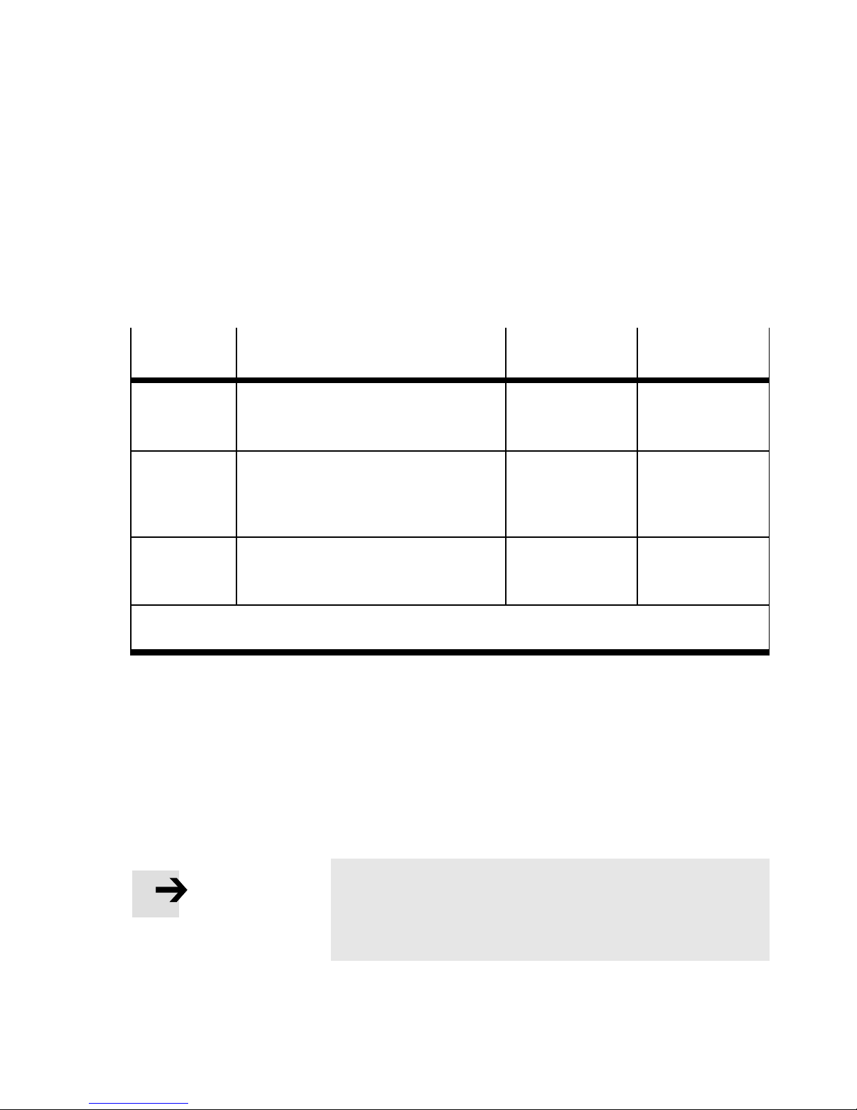
This manual includes information about the following
modules:
CPX bus node
Type
Description Connection technology
designation
CPX-M-FB20 CPX bus node for INTERBUS
with fibre optic cable (FOC)
CPX-M-FB21 2 Rugged Line sockets:
Tab. 0/1: Overview of CPX bus node for INTERBUS FOC
1 Rugged Line socket:
– 1 x fieldbus, incoming
– 1 x fieldbus, incoming
– 1 x fieldbus, continuing
VI
Festo P.BE-CPX-FB20/21-E N en 1202a

Contents and general safety instructions
This manual includes information about installation and
configuration of the CPX bus node for INTERBUS with fibre
optic cable (FOC) as well as INTERBUS-specific information
regarding parameterisation, commissioning, programming
and diagnosis of a CPX terminal in an INTERBUS network.
General basic information about the method of operation,
fitting, installation and commissioning of CPX terminals can
be found in the CPX system manual.
Information about further CPX modules can be found in the
manual for the respective module.
An overview of the structure of the CPX terminal user documentation is contained in the CPX system manual.
Product specific information about the control system can
be found in the manufacturer's product documentation
accompanying the product.
Festo P.BE-CPX-FB20/21-EN en 1202a
VII

Contents and general safety instructions
Important user instructions
Danger categories
This manual contains instructions on the possible dangers
which can occur if the product is not used correctly. These
instructions are marked (Warning, Caution, etc), printed on a
shaded background and marked additionally with a pictogram.
A distinction is made between the following danger warnings:
Warning
... means that failure to observe this instruction may result
in serious personal injury or damage to property .
Caution
... means that failure to observe this instruction may result
in personal injury or damage to property.
Note
... means that failure to observe this instruction may result
in damage to property.
The following pictogram marks passages in the text which
describe activities with electrostatically sensitive devices:
VIII
Electrostatic sensitive devices: inappropriate handling can
result in damage to components.
Festo P.BE-CPX-FB20/21-E N en 1202a

Contents and general safety instructions
Identification of specific information
The following pictograms designate texts that contain special
information.
Pictograms
Information:
Recommendations, tips and references to other sources of
information.
Accessories:
Information about necessary or useful accessories for the
Festo product.
Antipollution:
Information about the environmentally-friendly use of Festo
products.
Text designations
•
Bullet points indicate activities that may be carried out in
any order.
1. Numerals denote activities which must be carried out in
the numerical order specified.
– Arrowheads indicate general lists.
Festo P.BE-CPX-FB20/21-EN en 1202a
IX

Contents and general safety instructions
The following product-specific terms and abbreviations are
used in this manual:
T erm/abbreviation
CPX bus Data bus via which the CPX modules communicate with each other and
CPX modules Collective term for the various modules which can be integrated in a CPX
CPX terminal Modular electric terminal type 50
DIL switch Dual-in-line switches consist of several logic elements with which settings
Bus nodes Create the connection to certain networks or fieldbuses, conduct control
Handheld (MMI) Handheld terminal (handheld, CPX-MMI) for CPX modules for
I Digital input
I/O modules Collective term for the CPX modules which provide digital inputs and
I/Os Digital inputs and outputs
Meaning
are supplied with the necessary operating voltage.
terminal.
can be made.
signals to the connected modules and monitor their functioning.
commissioning and service purposes (Man-Machine Interface, MMI).
outputs (CPX input modules and CPX output modules).
O Digital output
PLC/IPC Programmable logic controller/industrial PC
Pneumatic interface The pneumatic interface is the interface between the modular elec trical
peripherals and the pneumatics.
VTSA… Pneumatic modules/valve terminal type 44/45
Tab. 0/2: CPX-specific terms and abbreviations
X
Festo P.BE-CPX-FB20/21-E N en 1202a

Contents and general safety instructions
The following Interbus-specific terms and abbreviations are
used in this manual:
T erm/abbreviation
CMD software Parameterisation, commissioning and diagnostic software for slaves on
FOC Fibre-optic cables
Ident. code By means of the Ident code (in brief: ID code), the module ascertains the
Module ThemoduleisthecentraldeviceforcheckingtheInterbusdataring.
Peripheral fault (PF) Faults in the peripherals of Interbus slaves are shown by means of
Process data I/O data from the Interbus slaves transmitted cyclically via the Interbus,
Meaning
the Interbus (configuration, monitoring, diagnosis).
type and the process data length of all the slaves.
It exchanges the data transported serially in the data ring with the
higher-order controller or computer system and the lower-order Interbus
slaves in both directions acyclically or cyclically .
peripheral faults ( dependent on slave), e.g.
– load voltage failure
– short circuit at the outputs, etc.
The peripheral fault is a common fault message which does not contain
any module-specific information.
e.g. for:
– light barriers, sensors
– valves, fuses
– diagnostic I/Os
Remote bus The remote bus bridges long distances within an Interbus system
Tab. 0/3: Interbus-specific terms and abbreviations
Festo P.BE-CPX-FB20/21-EN en 1202a
(main string). With baud rates of 500 kBd and 2 MBd it can be up to
12.8 km long (from the module to the last connected remote bus slave).
Individual segments can be up to 400 m long.
XI

Contents and general safety instructions
XII
Festo P.BE-CPX-FB20/21-E N en 1202a

Installation
Chapter 1
Installation
Festo P.BE-CPX-FB20/21-EN en 1202a
1-1

1. Installation
Contents
1. Installation 1-1...................................................
1.1 Fibre optic cable (FOC) connection 1-2.................................
1.2 General instructions on installation 1-3................................
1.3 Settings of the DIL switches on the bus node 1-6.........................
1.4 Connecting the fieldbus 1-11..........................................
1.4.1 System structure on the remote bus 1-11........................
1.4.2 Fieldbus interface assignment 1-13.............................
1.4.3 Connecting the fibre optic cable 1-15............................
1.4.4 Fieldbus baud rate and fieldbus length 1-21......................
1.5 Pin assignment of power supply 1-22...................................
1.5.1 Connecting the power supply US1/US2 1-24......................
1.5.2 Sealing unused connections in the Rugged Line plug 1-27..........
1-2
Festo P.BE-CPX-FB20/21-E N en 1202a

1. Installation
1.1 Fibre optic cable (FOC) c onnection
We recommend fibre optic cable technology for transmission
in environments subjected to heavy interference, as well as
for extending the range when high transmission speeds are
used.
This has the added advantage of high electromagnetic resistance to interference due to the optical transmission of the
signals.
Festo P.BE-CPX-FB20/21-EN en 1202a
1-3

1. Installation
1.2 General instructions on installation
Warning
Before carrying out installation and maintenance work,
switch off the following:
•
Compressed air supply
•
the operating voltage supply for the electronics/sensors
•
the load voltage supply for the outputs and valves
In this way, you can avoid:
– uncontrolled movements of loose tubing
– uncontrolled movements of the connected actuators
– non-defined switching states of the electronic components.
Caution
The CPX bus node for Interbus includes electrostatically
sensitive devices.
•
Do not therefore touch any components
•
Observe the handling specifications for electrostatically
sensitive devices.
They will help you avoid damage to the electronics.
1-4
Festo P.BE-CPX-FB20/21-E N en 1202a

1. Installation
1
Fieldbus
connection IN
(incoming,
Rugged Line
plug)
Electrical connection and display components
The following connection and display components can be
found on the CPX bus node F B20 for the Interbus fibre-optic
cable:
2
Bus-statusspecific and
CPX-specific LEDs
3
Service interface
for handheld, etc.
4
DIL switch under
cover
4
3
2
Fig. 1/1: Connection and display components on the CPX bus node FB20
1
Festo P.BE-CPX-FB20/21-EN en 1202a
1-5

1. Installation
1
Fieldbus
connection OUT
(continuing,
Rugged Line
plug)
2
Fieldbus
connection IN
(incoming,
Rugged Line
plug)
3
Bus-statusspecific and
CPX-specific LEDs
4
Service interface
for handheld, etc.
5
DILswitchunder
cover
Fig. 1/2: Connection and display components on the CPX bus node FB21
5
4
3
12
1-6
Festo P.BE-CPX-FB20/21-E N en 1202a

1. Installation
1.3 Settings of the DIL switches on the bus node
There are 8 DIL switches available for configuring the bus
node. These are located under a cover to the left above the
Rugged Line connection (see Fig. 1/1 and Fig. 1/2).
1
DIL switch 1:
Baud rate
2
DIL switches
2, 7 and 8:
Reserved
1
2
3
2
3
DIL switches 5 and 6:
Diagnostic mode
4
DIL switch 4:
Error message
5
DIL switch 3:
Data format
Fig. 1/3: DIL switches on the bus node
(Additional information on 1 ... 5 see following pages)
Procedure:
1. Switch off the power supply.
2. Remove either the fitted fieldbus plugs or the cover, as
required.
3. Set the DIL switches as described on the following pages.
The following applies:
5
4
Festo P.BE-CPX-FB20/21-EN en 1202a
– DI L switch in upper position = ON
– DIL switch in lower position = OFF
4. Refit either the fieldbus plugs or the cover, as required.
Tighten the fastening screws at first by hand and then
with 0.3 Nm.
1-7

1. Installation
ThesettingoftheDILswitchhasprecedenceovertheparameterisation of defined settings.
Baud rate
Set the operating mode of the CPX-terminal with DIL switch 1:
Baud rate
500 kBd 1: OFF
2MBd 1: ON
DIL switch 1
(default)
Tab. 1/1: DIL switch 1
Data format
Set the data format with DIL switch 3:
Data format
Standard 3: OFF
DIL switch element 3
(default)
1-8
Siemens (Byte swap) 3: ON
Tab. 1/2: DIL switch 3
Festo P.BE-CPX-FB20/21-E N en 1202a

1. Installation
Error message
Use DIL switch 4 to determine whether the undervoltage error
message should be registered:
Error message
Register undervoltage V
as peripheral fault
Do not register
undervoltage V
load
load
Tab. 1/3: DIL switch 4
DIL switch 4
4: OFF
(default)
4: ON
Festo P.BE-CPX-FB20/21-EN en 1202a
1-9

1. Installation
Diagnostic mode
Set the diagnostic mode with DIL switches 5 and 6:
Peripheral fault mode
Diagnostic mode 1 (M1):
– No diagnosis
– No assignment in the
image table for inputs
Diagnostic mode 2 (M2):
– With diagnosis
– Diagnosis occupies 4 bytes
at the start of the image
table for inputs
Diagnostic mode 3 (M3):
– With diagnosis
– Diagnosis occupies 2 bytes
at the end of the image
table for inputs
Diagnostic mode 4 (M4):
– With diagnosis
– Diagnosis occupies 4 bytes
at the end of the image
table for inputs
DIL switches 5 and 6
5: OFF
6: OFF
(default)
5: OFF
6: ON
5: ON
6: OFF
5: ON
6: ON
1-10
T ab. 1/4: DIL switches 5 and 6
Festo P.BE-CPX-FB20/21-E N en 1202a

1. Installation
Reserved DIL switches
DIL switches 2, 7 and 8 are reserved for future expansion.
Reserved DIL switches
--- 2OFF
DIL switches 2, 7 and 8
7: OFF
8: OFF
(default)
Tab. 1/5: DIL switches 2, 7 and 8
Festo P.BE-CPX-FB20/21-EN en 1202a
1-11

1. Installation
1.4 Connecting the fieldbus
There are one (FB20) or two (FB21) connections on the node
for connecting the Interbus. One connection is for the incoming line; the other is intended for the continuing bus cable.
Observe the differences in the remote bus, which are listed
below.
Note
Faulty installation and high transmission rates may cause
data transmission errors as a result of signal attenuations.
Transmission errors can be caused by:
– transmission over distances which are too long
– inappropriate cables.
Observe the cable specifications! Obtain information about
the cable type to be used from the manual for the interface
module or from the Interbus installation manual.
1.4.1 System structure on the remote bus
The CPX terminal with bus node FB20/21 is a fibre-optic
remote bus par ticipant on the Interbus with Rugged Line
connection technology. Dependent on the modules used, it
reacts to the remote bus like a fibre-optic bus terminal with
integrated I/Os and it must be addressed accordingly.
Note
– Commissioning on the remote bus can only take place if
all slaves are completely connected, or if they are
bridged by means of a software setting.
1-12
– The CPX terminal requires a 24 V DC power supply.
This is supplied via the Rugged Line plug. It is possible
to supply and switch off separately the valve terminal
outputs/valves.
Festo P.BE-CPX-FB20/21-E N en 1202a

1. Installation
24 V DC
1
230 V AC
1
23
4
1
Interbus master: PC or PLC with module
2
CPX terminal: Onl y electric I/O modules
3
CPX terminal: VTSA valves and electric I/O modules
4
Further Interbus slaves
Fig. 1/4: Remote bus system structure with CPX terminals
Festo P.BE-CPX-FB20/21-EN en 1202a
1-13

1. Installation
Remote bus
The bus node has been prepared for operation on the remote
bus.
Further information on installing an Interbus system can be
found in the Interbus installation manual.
Installation manual
IBS SYS INST UM 27 54 28 6
Obtainable from:
Phoenix Contact Deutschland GmbH
Postfach 1341
32825 Blomberg, Germany
1.4.2 Fieldbus interface assignment
Required accessories from Phoenix Contact for connecting
the bus node FB20 and FN21 can be found in Appendix A.
A Rugged Line IN connection (remote bus), as well as a
Rugged Line OUT connection (remote bus) in the case of the
FB21, can be found on the bus node for connecting the CPX
terminal to the fieldbus.
Order no. Phoenix
1-14
These connections serve for the incoming (IN) and continuing
(OUT) fieldbus cable.
Festo P.BE-CPX-FB20/21-E N en 1202a

1. Installation
Plugs Pin Bus connection (fibre optic cable) in first Rugged Line plug,
incoming
OUTINTransmitted data, wire colour = black
Received data, wire colour = orange
OUT
IN
Plugs Pin Bus connection (fibre optic cable) in se cond Rugged Line plug,
continuing (FB21 only)
OUTINTransmitted data, wire colour = orange
Received data, wire colour = black
OUT
IN
Tab. 1/6: Connection assignment of bus connection (remote bus)
Festo P.BE-CPX-FB20/21-EN en 1202a
1-15

1. Installation
1.4.3 Connecting the fibre optic cable
Preparing
Note
– Only use the fibre optic cable from Phoenix Contact
(see Appendix A, Tab. A/5).
– Only the following procedure is suitable for removing the
outer red insulation coating:
– The fibre optic cable must be at least 12 cm longer than
required, as the cable must be shortened by this length
when the insulation is removed (see following pos. 7).
Proceed as follows:
1. The cable must be cut in a longitudinal direction.
The cable cross-section must be turned so that the
longitudinal cut is on the side facing the aramide yarn.
2. Place the cable cutter (KAMES LWL) on the cable coating
approx. 10 cm from the end of the cable and pull it in a
longitudinal direction (see Fig. 1/5, diagram A). If necessary, repeat the step until the cable coating has been cut.
3. Loosen the strain relief (aramide yarn) from the cable
coating which has been cut open (see Fig. 1/5, diagram B).
4. Wind the aramide yarn onto a mandril (e.g. screwdriver,
pliers) and protect it against rolling off (see Fig. 1/5,
diagram C).
5. Tear open the outer red cable coating approx. a further
15 cm with the aramide yarn without bending the cable
(see Fig. 1/5, diagram C).
1-16
Festo P.BE-CPX-FB20/21-E N en 1202a

1. Installation
Note
The two individual cores must not be damaged.
6. Use a sharp diagonal cutter to cut off the outer red cable
coating and the strain relief at the start of the cut area,
without damaging the two individual cores (see Fig. 1/5,
diagram D).
7. Shorten the individual cores by 12 cm, as this part may
have been damaged when the insulation was removed
with the cable cutter (see Fig. 1/5, diagram D).
1
A
B
D
Cable stripper “Kames 1” from Phoenix Contact
1
C
Fig. 1/5: Removing the outer cable insulation
Festo P.BE-CPX-FB20/21-EN en 1202a
1-17

1. Installation
Connecting
Proceed as follows:
1. Break through the sealing rubber with a screwdriver.
2. Place the Quickon screw, the clamping box and the sealing rubber on the polymer fibre cable. The sealing rubber
must be flush with the edge of the insulation (see Fig. 1/6,
diagram A).
3. Push both black cores through the splice ring. The
smooth side of the splice ring must face towards the
cable.
Note
– Note the marking IN/OUT on the splice ring.
– Cross the individual cores on the opposite splice ring
(see Fig. 1/6, Pos. 5 ).
– If you have inserted the individual cores incorrectly in
the splice ring, you must not turn the cores, as they will
then be damaged.
4. Push both black cores through the appropriate opening in
the Rugged Line plug until they project at the other end
(see Fig. 1/6, diagram B).
1-18
Festo P.BE-CPX-FB20/21-E N en 1202a

1. Installation
5. Tighten the Quickon screw with the fibre cutter (Phoenix
Contact, type IBS RL FOC). This provides strain relief
(see Fig. 1/6, diagram C).
6. Push the fibre cutter as far as possible onto the projecting
cores on the Rugged Line plug (see Fig. 1/6, diagram D).
7. Cut off the individual cores.
12
A
C
1
Quickon screw
2
Clamping box
3
Sealing rubber
3 4 5
D
B
4
Splice ring
5
Crossing the fibre optic cable with
remote IN and OUT
6
Fibre cutter
6
Fig. 1/6: Connecting the fibre optic cable
Festo P.BE-CPX-FB20/21-EN en 1202a
1-19

1. Installation
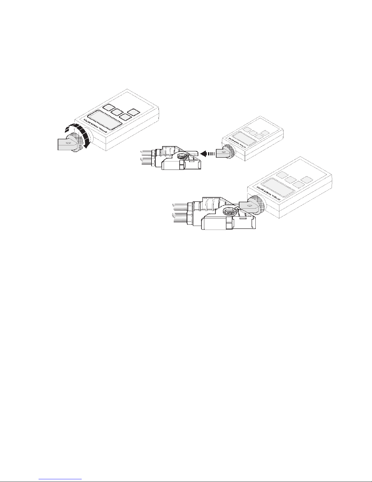
Checking the fibre optic cable connection
When a fibre optic cable has been installed, you can check
the optical performance in front of the receiving device with a
fibre optical measuring unit (see Appendix A, Tab. A/5).
Proceed as follows:
1. Clean the optical active range of the measuring unit with a
clean cloth free of fluff.
2. Screw the measuring unit adapter onto the measuring
unit.
3. Place the measuring unit with the measuring unit adapter
on the longer of the two remote bus connections on the
Rugged Line plug.
4. Set the measuring unit to 660 nm.
5. Measure the optical performance.
For reliable data transmission, the measured level must
not exceed a value of -3.6 dBm or drop below a value of
-18.0 dBm.
This level takes into account the performance drift of the send
and receive components and a system reserve of 3 dB.
1-20
Festo P.BE-CPX-FB20/21-E N en 1202a
1. Installation
A
B
C
Fig. 1/7: Placing the measuring unit adapter
Festo P.BE-CPX-FB20/21-EN en 1202a
1-21

1. Installation
Fieldbus cable
Bus length Details concerning the bus length can be found in Appendix A.
Note
If the valve terminal is mounted into a moving part of a
machine, the fieldbus cable on the moving part must be
provided with strain relief. Please also observe the relevant
regulations in EN 60204 part 1.
1.4.4 Fieldbus baud rate and fieldbus length
The maximum permissible fieldbus length is dependent on
thefibre-opticcableused.Thebaudrateis500or
2000kbit s.
1-22
Festo P.BE-CPX-FB20/21-E N en 1202a

1. Installation
1.5 Pin assignment of power supply
Warning
•
Only use PELV circuits as per IEC/EN 60204-1 (protective
extra-low voltage, PELV) for the electrical power supply.
•
Observe also the general requirements of IEC/DIN EN
60204-1 for PELV circuits.
•
Only use voltage sources, which guarantee reliable electrical isolation of the operating voltage as per IEC/EN
60204-1.
The use of PELV circuits ensures protection from electric
shock (protection from direct and indirect contact) in
accordance with IEC/EN 60204-1 (Electrical equipment of
machines, General requirements).
The current consumption of a CPX terminal depends on the
number and type of integrated modules and components.
Observe the information on power supply and the required
earthing measures in the CPX system description.
Festo P.BE-CPX-FB20/21-EN en 1202a
1-23

1. Installation
Plugs Pin Operating voltage connection in the Rugged Line plug
25
3
1
1
2
3
4
5
4
24 V supply for electronics, inputs
0 V electronics, inputs
24 V supply, valves, outputs
0 V valves, outputs
Functional earth
Tab. 1/7: Pin assignment of bus connection (power supply)
1-24
Festo P.BE-CPX-FB20/21-E N en 1202a

1. Installation
1.5.1 Connecting the power supply US1/U
These fitting instructions apply to the fibre optical Rugged
Line plug from Phoenix Contact.
Note
Use a power supply cable 5 x 1.5 mm
Contact (see Appendix A, Tab. A/5). The numbers printed
on this cable correspond to the numbering on the splice
ringoftheRuggedLineplug.
Proceed as follows:
1. Break through the sealing rubber with a screwdriver.
2. Push the Quickon screw, the clamping box and the sealing
rubber over the power supply cable (see Fig. 1/8
diagram A).
3. Remove the insulation coating over a length of approx.
10 cm.
S2
2
, e.g. from Phoenix
4. Push first the sealing rubber to the edge of the insulation,
then push the clamping box onto the sealing rubber
(see Fig. 1/8, diagram B). This forms the strain relief for
the cable.
Festo P.BE-CPX-FB20/21-EN en 1202a
1-25

1. Installation
5. Push the ends of the cable cores into the appropriate
openings on the splice ring (see Fig. 1/8, diagram C).
The numbers printed on the cable correspond to the
numbering on the splice ring.
6. Pull hard on the ends of the cores.
7. Cut off the projecting ends of the cores. Make sure that
the ends of the cores are flush with the splice ring, do not
project, and are not too short (see Fig. 1/8, diagram D).
8. Insert the ready-to-use cable into the appropriate connection on the Rugged Line plug (see Fig. 1/8, diagram E).
9. Turn the ready-to-use cable until the coding lugs of the
splice ring fit exactly into the appropriate guides of the
Rugged Line plug.
10. Tighten the Quickon screw with the fibre cutter
(see Fig. 1/8, diagram F). The insulation will then be cut
and the electrical contact restored.
Note
If you wish to connect the cable cores again, you must cut
them again, as otherwise the electrical contact cannot be
guaranteed.
1-26
Festo P.BE-CPX-FB20/21-E N en 1202a

1. Installation
12
3 4
A
E
5
B
C
D
F
QUICKON screw
1
2
Clamping box
3
Sealing rubber
Fig. 1/8: Connecting the power supply cable to the Rugged Line plug
4
Splice ring
5
Rugged Line plug
Festo P.BE-CPX-FB20/21-EN en 1202a
1-27

1. Installation
Additional power supply The outputs are supplied with load voltage via the
interlinking blocks with additional power supply
CPX-M-GE-EV-Z-7/8-5POL or CPX-M-GE-EV-Z-PP-5POL.
Plugs
2
3
4
1234 5
V
: Load voltage for outputs
OUT
Pin assignment for additional po wer supply
Additional power supply type CPX-M-GE-EV-Z-7/8-5POL
1
1: 0 V
Out
2: Unused
5
3: FE
Additional power supply type CPX-M-GE-EV-Z-PP-5POL (Push Pull)
1: Not connected
2: Not connected
3: 24 V
Out
4: Unused
5: 24 V
4: 0 V
5: FE
Out
Out
Tab. 1/8: Pin allocation: Additional power supply for outputs
1.5.2 Sealing unused connections in the Rugged Line plug
1-28
Note
•
Seal unused connections in the Rugged Line plug.
•
Use only sealing rubber which has not been broken
through.
You can then be sure of complying with protection class
IP65/67.
Festo P.BE-CPX-FB20/21-E N en 1202a

1. Installation
3
4
Proceed as follows:
1. Place the clamping ring on the sealing rubber
(see Fig. 1/9, diagram B or Fig. 1/10, diagram B).
2. Place both together in the Quickon screw.
3. Place the appropriate splice ring in the non-required
connection of the power supply or of the fibre optical
waveguide in the Rugged Line plug.
4. Place the screw connector in position and tighten the
Quickon screw with the fibre cutter (see Fig. 1/9,
diagram C or Fig. 1/10, diagram C).
12
A
1
Quickon screw
B
3
Sealing rubber
C
2
Clamping box
Fig. 1/9: Sealing a non-used power supply connection
Festo P.BE-CPX-FB20/21-EN en 1202a
4
Splice ring
1-29

1. Installation
4
12
A
1
Quickon screw
2
Clamping box
3
B
3
Sealing rubber
4
Splice ring
C
Fig. 1/10: Sealing a non-used fibre optical waveguide connection
1-30
Festo P.BE-CPX-FB20/21-E N en 1202a

Commissioning
Chapter 2
Commissioning
Festo P.BE-CPX-FB20/21-EN en 1202a
2-1

2. Commissioning
Contents
2. Commissioning 2-1................................................
2.1 Configuration and addressing 2-2.....................................
2.1.1 Ascertaining the address range 2-2............................
2.1.2 Address assignment of the CPX terminal 2-7.....................
2.1.3 Address assignment after extension/conversion 2-15..............
2.1.4 Bus configuration and addressing 2-18..........................
2.1.5 Switching on the power supply 2-19............................
2.1.6 Bus configuration with the CMD software 2-20....................
2.1.7 Bus configuration without CMD software 2-28....................
2.1.8 Process data entry via the CMD software 2-29....................
2.2 Parameterisation 2-33...............................................
2.2.1 Parameterisation concepts 2-35................................
2.3 Commissioning the CPX terminal on the Interbus 2-37.....................
2.3.1 Fail safe 2-38...............................................
2-2
Festo P.BE-CPX-FB20/21-E N en 1202a

2. Commissioning
2.1 Configuration and addressing
2.1.1 Ascertaining the address range
Before configuring, ascertain the exact number of available
inputs/outputs. Depending on what you have ordered, a CPX
terminal comprises a different number of I/Os.
Note
– The maximum possible extension to the CPX terminal
with Interbus bus node is limited to 96 inputs and outputs.
The I/Os will be assigned automatically within the CPX terminal.
Festo P.BE-CPX-FB20/21-EN en 1202a
2-3

2. Commissioning
Available inputs
Depending on the setting of DIL switches 5 and 6, the CPX
terminal supports the following maximum number of inputs
to the I/O modules.
Setting
Maximum number of
available inputs
Diagnostics mode
M1: No diagnosis 96 inputs
M2: With 4 byte diagnosis 64 inputs
M3: With 2 byte diagnosis 80 inputs
M4: With 4 byte diagnosis 64 inputs
1)
For diagnosis modes also refer to Tab. 1/4
1)
Tab. 2/1: Number of available inputs and outputs
The I/Os will be assigned automatically within the CPX terminal.
The address assignment within the individual modules can be
found in the manual for the relevant module.
2-4
Festo P.BE-CPX-FB20/21-E N en 1202a

2. Commissioning
On the basis of the module type, you can ascertain the number of inputs and outputs occupied by the module.
The individual modules are displayed with their identifier on
the handheld. In the case of the I/O modules, the identifier is
also shown in the LED viewing window.
Electric modules
Type Module
identifier
Bus node FB20/21, Remote I/O,
without system diagnostics
Bus node FB20/21, remote I/O, with diagnostics
– Diagnostic mode 2
– Diagnostic mode 3
– Diagnostic mode 4
Digital 4-input module CPX-4DE 4DI 4I –
Digital 8-input module CPX-8DE 8DI 8I –
Digital 8-off input module with channel
diagnostics
Digital 16-off input module CPX-16DE 16DI 16 I –
Digital 16-off input module with c hannel
diagnostics
2)
2)
CPX-M-FB20
CPX-M-FB21
CPX-8DE-D 8DI-D 8I –
CPX-16DE-D 16DI-D 16 I –
FB21-RIO – –
Assigned addresses
1)
Inputs Outputs
32 I
16 I
32 I
Digital 8-off input module n-switching CPX-8NDE 8NDI 8I –
Digital 4-way output module CPX-4DA 4DO – 4O
Digital 8-off output module CPX-8DA 8DO – 8O
Digital 8-off output module, high-current variant
Digital multi I/O module CPX-8DE-8DA 8DI/8DO 8I 8O
1)
Module identifiers on the handheld, on I/O modules these are shown in the viewing window.
2)
The diagnostics mode is activated by DIL switch 5 and 6 (see Tab. 1/4).
Tab. 2/2: Overview of identifiers and addresses of the electric modules (part 1)
Festo P.BE-CPX-FB20/21-EN en 1202a
CPX-8DA-H 8DO-H – 8O
2-5

2. Commissioning
Electric modules Type Module
identifier
Analogue 2-off input module CPX-2AE-U-I 2AI 32 I –
Analogue 4-off input module CPX-4AE-U-I 4AI 64 I –
Analogue 4-off input module CPX-4AE-I 4AI-I 64 I –
Analogue 4-off input module
(temperature module)
Analogue 2-off output module CPX-2AA-U-I 2AO – 32 O
1)
Module identifiers on the handheld device, on I/O modules these are shown in the inspection
window.
CPX-4AE-T 4AI-T 32/64 I
Assigned ad-
1)
dresses
Inputs Outputs
2)
–
Tab. 2/3: Overview of identifiers and addresses of the electric modules (part 2)
Pneumatic interfaces for
VTSA...
Type Module
identifier
Assigned addresses
1)
Inputs Outputs
Pneumatic interface for
VTSA… valves (type 44/45)
with DIL switch setting:
– 1 ... 8 valve c oils
– 1 ... 16 valve coils
– 1 ... 24 valve coils
– 1 ... 32 valve coils
1)
Module identifier in the Handheld.
2)
The number of output addresses occupied by the pneumatic modules of the VTSA… is set on the
pneumatic interface with a DIL switch (see manual for the CPX I/O modules).
2)
VABA-10S6-x1 VTSA,
ISO Plug In or
TYPE 44 or
TYPE 45
–
Tab. 2/4: Overview of identifiers and addresses of pneumatic modules
The complete address range of the I/Os including diagnosis
always contains an equal number of inputs and outputs.
Tip:
Copy the following table for further calculations.
8O
16 O
24 O
32 O
2-6
Festo P.BE-CPX-FB20/21-E N en 1202a

2. Commissioning
Calculating the number of inputs/outputs
Use the following table for calculating the number of inputs
and outputs on your CPX terminal.
Input/output modules and system
1. Number of input modulesCPX-4DE + __ x 4 I
2. Number of input modules CPX-8DE, -8NDE, -8DE-D + __ x 8 I
3. Number of input modules CPX-16DE + __ x 16 I
4. Number of output modules CPX-4DA + __ x 4 O
5. Number of output modules CPX-8DA + __ x 8 O
6. Number of multi I/O modules CPX-8DE-8DA + __ x 8
I/O
7. Number of inputs and outputs of other modules + __ I/O
(e.g. analogue modules)
8. VTSA... pneumatic interface:
Number of configured valve solenoid coils (+ 8 O, 16 O, 24 O, 32
O)
32 O are configured at the factory!
7. Inputs and outputs of the modules
Sum of 1 to 6:
8.. Diagnostics if set
Diagnosis M2 and M4 + 32 I
Diagnostics M3 + 16 I
Check whether the greater value (inputs)
from item 8 is divisible by 16 without remainder (diagnostics
begins with the next word):
a) if divisible by 16 without remainder: + 0 I
b) if the remainder = 12: round up to the next word. + 4 I
c) if the remainder = 8: round up to the next word. + 8 I
d) if the remainder = 4: round up to the next word. + 12 I
Inputs Outputs
+ _____ I
+ _____ I
+ _____ I
+ _____ O
+ _____ O
+ _____ I
+ _____ I
= ∑ _____ I = ∑ _____ O
+ _____ I
+ _____ I
+ _____ I
+ _____ O
+ _____ O
+ _____ O
9. Inputs and outputs of the modules
Sum of 7 to 8:
Sum total of inputs/outputs to be configured
Greater value (inputs or outputs) from 9: _____ I/O
1)
The maximum number of the available I/Os from Tab. 2/1 must not be exceeded.
Tab. 2/5: Ascertaining the number of inputs and outputs
Festo P.BE-CPX-FB20/21-EN en 1202a
= ∑ _____ I = ∑ _____ O
1)
2-7

2. Commissioning
2.1.2 Address assignment of the CPX terminal
Basic rules for addressing
Inputs and outputs
– The address assignment of the inputs does not depend on
the outputs.
– The counting mode is independent of the position of the
bus node.
– Counting from left to right.
– The setting for the number of valves on the pneumatic
interface of 1 and 3 bytes is always rounded up to the full
word (2 or 4 bytes).
– Sequence:
– For diagnostics mode 2:
32 diagnostic bits in front of the input bits.
– Input/output words of the analogue modules,
– Input/output words of the function modules (word-
orientated),
– Input/output bits of the electric inputs and outputs
(including valves):
– For diagnostics mode 3:
16 diagnostic bits followed by the input bits from the
next word.
2-8
– For diagnostics mode 4:
32 diagnostic bits followed by the input bits from the
next word.
Festo P.BE-CPX-FB20/21-E N en 1202a

2. Commissioning
Note
If two addresses are assigned for one valve location, the
following applies:
– lower-value address: pilot solenoid 14
– higher-value address: pilot solenoid 12
Address assignment on the Interbus
The address assignment (processing data assignment) of the
inputs and outputs of a CPX terminal on the Interbus depends
aboveallontheInterbusmoduleandonthecontrolsystem
used.
Caution
There are different address assignments on the Interbus.
The reason for this is the assignment of the processing
data within the Interbus module.
•
When assigning the addresses, note the position of the
high and low bytes, as the position of these bytes may
be swapped in conjunction with some control systems.
You can then avoid faults in addressing the inputs/outputs.
Further details on addressing can be found in the manuals for
your controller and for the Interbus module.
The following examples provide basic information on the
different address assignments and the positions of the low
byte (n) and the high byte (n+1) with various controllers.
There are two modes:
–IntheSiemens mode the lower-value input or output byte
(byte n) is mapped on inputs or outputs 0 ... 7, byte n+1
on the next inputs or outputs (8 ... 15) etc.
Festo P.BE-CPX-FB20/21-EN en 1202a
2-9

2. Commissioning
–IntheStandard mode the lower-value input or output
byte (byte n) is mapped on inputs or outputs 8 ... 15,
byte n+1 on the inputs or outputs 0 ... 7.
This allocation also applies to the bytes of diagnostics
M2…M4.
In section 2.1.8 you will find instructions on addressing with
the CMD software (processing data assignment) and on
modifying the position of the low and high bytes (“byte swap”).
Note
Thebyteswapcaneither be set via DIL switch 1.3 or with
the help of the CMD software. If the byte swap is set via
DIL switch and CMD, then the settings override each other!
Examples for the address assignment of the CPX
terminal
The following examples show the assignment of the input and
output bytes to the individual modules. In the examples the
following applies:
– Configured input address: IB20
Configured output address: OB20
– The address assignment is represented both in the
Siemens mode and in the Standard mode.
The address assignment within the individual I/O modules
canbefoundinthemanualfortheI/Omodules.
The address assignment within the pneumatic modules can
be found in the manual for the valve terminal pneumatics.
2-10
Festo P.BE-CPX-FB20/21-E N en 1202a

2. Commissioning
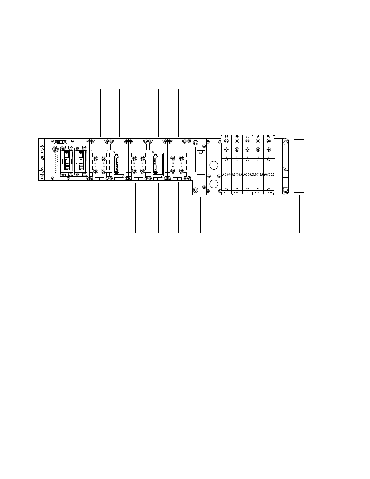
The modules and diagnostic modes are represented in the
examples as follows:
8DI 8DI 8DO 4DO4DI 4DO
16 O
123454 67
1
Bus node CPX-FB20 or FB21
2
8DI: 8-off input module
3
4DI: 4-off input module
4
4DO: 4-off output module
5
8DI 8DO: multi I/O module
6
VTSA… pneumatic interface with the
number of outputs set by DIL switches,
here with 16 O
Fig. 2/1: Identification of the modules in the examples
7
Input addresses for diagnostics:
Inputs are assigned for the diagnostics
dependent on the DIL switch setting:
– 0 I-bits, no diagnostics (diagnostics
M1) or
– 16 I-bits, diagnostics M3
– 32 I-bits, diagnostics M2 or M4
The inputs for diagnostic mode 3 are
always assigned in the following examples.
Diagnostics M2 … M4
Festo P.BE-CPX-FB20/21-EN en 1202a
2-11

2. Commissioning
Byte assignment
of the input by tes
Siemens mode:
IB 20
Example 1
I/O modules and VTSA pneumatics (setting 8 O)
IB 21 IB 22 IB 24
IB 23
IB 25
Standard mode:
Byte assignment
of the output bytes
Siemens mode:
Standard mode:
IB = input byte; OB = output byte; diagnostics optional
IB 21 IB 20 IB 23 IB 25
8DI 8DI 8DO 4DO8DI 8DO 4DO
OB 22 OB 23 OB 20 OB 21
OB 23 OB 22 OB 21 OB 20
IB 22
8O
Fig. 2/2: Example 1 – byte assignment in Siemens and Standard modes
IB 24
Diagnostics M3
2-12
Festo P.BE-CPX-FB20/21-E N en 1202a

2. Commissioning
Address assignment in Siemens
mode
I20.0 ... I20.7
8DI 8DI 8DO 4DO
I21.0 ... I21.7
O20.0 ... O20.7
8DI 8DO 4DO
O22.0 ... O22.3
I22.0 ... I22.7
O22.4 ... O23.3
O21.0 ... O21.7
O23.4 ... O23.7
I24.0 ... I24.7
I25.0 ...I25.7
8O
Address assignment
in Standard mode
I21.0 ... I21.7
Diagnostics optio nal
I20.0 ... I20.7
O21.0 ... O21.7
O23.0 ... O23.3
I23.0 ... I23.7
O22.4 ... O22.7
O23.4 ... O23.7
O22.0 ... O22.3
O20.0 ... O20.7
Fig. 2/3: Example 1 – address assignment in Siemens and Standard modes
Diagnostics M3
I25.0 ...I25.7
I24.0 ... I24.7
Festo P.BE-CPX-FB20/21-EN en 1202a
2-13

2. Commissioning
Byte assignment
of the input by tes
Siemens mode:
IB 20
Example 2
I/O modules and VTSA pneumatics (setting 16 O)
IB 21 IB 22 IB 23 IB 25
IB 24
Standard mode:
4DI
Byte assignment
of the output bytes
Siemens mode:
Standard mode:
IB = input byte; OB = output byte; diagnostics optional
IB 21 IB 20 IB 23 IB 22 IB 24
4DO 4DO 8DI8DI 8DO
OB 22 OB 23 OB 20 OB 21
OB 23 OB 22 OB 21 OB 20
16 O
IB 25
Fig. 2/4: Example 2 – byte assignment in Siemens and Standard modes
Diagnostics M3
2-14
Festo P.BE-CPX-FB20/21-E N en 1202a

2. Commissioning
Byte assignment
of the input by tes
Siemens mode:
IB 20
Example 3
I-module and VTSA pneumatics (setting 32 O)
IB 21 IB 22
IB 23
Standard mode:
Byte assignment
of the output bytes
Siemens mode:
Standard mode:
IB = input byte; OB = output byte; diagnostics optional
IB 21 IB 20 IB 22
4DI
32 O
OB 20 OB 21 OB 22 OB 23
OB 21 OB 20 OB 23 OB 22
IB 23
Fig. 2/5: Example 3 – byte assignment in Siemens and Standard modes
Diagnostics M3
Festo P.BE-CPX-FB20/21-EN en 1202a
2-15

2. Commissioning
2.1.3 Address assignment after extension/conversion
A speciality of the CPX terminal is its flexibility . If the demands
placed on the machine change, the equipment fitted on the
CPX terminal can also be modified.
Caution
If the CPX terminal is extended or converted at a later
stage, the input/output addresses may be shifted. This
applies in the following cases:
– if additional modules are inserted between existing
modules
– if existing modules are removed or replaced by other
modules which have more or fewer input/output
addresses
– VTSA... manifold sub-bases for monostable valves are
replaced by manifold sub-bases for bistable valves – or
vice versa (see pneumatics manual).
– Additional VTSA... manifold sub-bases are inserted
between existing bases.
– The configured addresses of the pneumatic interface are
modified.
Note
If the configuration is modified, the addresses of
diagnostics M3 or M4 may also be shifted if necessary!
2-16
Festo P.BE-CPX-FB20/21-E N en 1202a

2. Commissioning
Byte assignment
of the input by tes
Siemens mode:
IB 20
The following diagram shows the changes which occur to the
address assignment when the equipment fitted in example 1
is modified. On the I/O module side an 8-input module has
been replaced by a 4-input module. On the valve side, a valve
plate has been added and the pneumatic interface has been
set to 16 O.
IB 21 IB 22 IB 23 IB 24
IB 25
Standard mode:
Byte assignment
of the output bytes
Siemens mode:
Standard mode:
IB = input byte; OB = output byte; diagnostics optional
IB 21 IB 20 IB 23 IB 22 IB 25
4DI 8DI 8DO 4DO 8DI 8DO 4DO
OB 22 OB 23 OB 24 OB 25 OB 20
OB 23 OB 22 OB 25 OB 24 OB 21
16 O
IB 24
OB 21
OB 20
Fig. 2/6: Byte assignment of a CPX terminal after extension/conversion
Diagnostics M3
Festo P.BE-CPX-FB20/21-EN en 1202a
2-17
2. Commissioning
Address assignment in Siemens
mode
I20.0 ... I20.3
4DI 8DI 8DO 4DO 8DI 8DO 4DO
I20.4 ... I21.3
O22.0 ... O22.7
I21.4 ... I22.3
O23.0 ... O23.3
O23.4 ...O24.3
O21.0 ... O21.7
O24.4 ... O24.7
O20.0 ... O20.7
I24.0 ... I25.7
16 O
Address assignment
in Standard mode
I21.0 ... I21.3
Diagnostics optio nal
I20.0 ... I20.3
I21.4 ... I21.7
O23.0 ... O23.7
I23.0 ... I23.3
O22.0 ... O22.3
O22.4 ... O22.7
I20.4 ... I20.7
O25.4 ...O25.7
O25.0 ... O25.3
O21.0 ... O21.7
O20.0 ... O20.7
Fig. 2/7: Address assignment of a CPX terminal after extension/conversion
Diagnostics M3
I25.0 ...I25.7
I24.0 ... I24.7
2-18
Festo P.BE-CPX-FB20/21-E N en 1202a

2. Commissioning
2.1.4 Bus configuration and addressing
General instructions on commissioning
Before commissioning or programming, compile a configuration list of all connected fieldbus slaves. On the basis of this
list you can:
– carry out a comparison between NOMINAL and ACTUAL
configurations, in order to recognize connection faults.
– access these specifications during the syntax check of a
program, in order to avoid addressing faults
Configuration of the CPX terminal demands a very accurate
procedure, as different configuration specifications are sometimes necessary for each slave on the Interbus, due to the
modular structure. Note here the specifications in the sections which follow.
Festo P.BE-CPX-FB20/21-EN en 1202a
2-19

2. Commissioning
2.1.5 Switching on the power supply
Note
Note also the instructions in the manual for your controller
with Interbus module.
When the controller with Interbus module is switched on, it
automatically carries out a comparison between the
NOMINAL and ACTUAL configurations. It is important for this
configuration run that:
– the configuration specifications are complete and correct
– the fieldbus slaves are supplied with power, in order that
they can be recognised when the ACTUAL configuration is
ascertained.
Therefore, switch on the power supply for all the fieldbus
slaves simultaneously, e.g. via a central switch. Alternatively
switch on the power supply in the following sequence:
1. First the power supply for all the fieldbus slaves,
2. then the power supply for the controller.
2-20
Festo P.BE-CPX-FB20/21-E N en 1202a

2. Commissioning
2.1.6 Bus configuration with the CMD software
This section describes as an example the main steps within
the CMD software for inserting a CPX terminal in your project.
A general and comprehensive description can be found in the
relevant manual for the CMD software. In the following it is
assumed that the user is familiar with the contents of the
CMD manual.
Note
Note that software packages are often updated, so that
modifications to the software may not yet be taken into
accountinthismanual.
The examples used here for the screen displays have been
taken from CMD software version 4.50.
Festo P.BE-CPX-FB20/21-EN en 1202a
2-21

2. Commissioning
Inserting with Ident. code
Proceed as follows:
1. Click on the module with the right-hand mouse button.
2. Select the command “Insert with ID code...” in the context
menu.
Fig. 2/8: Inserting bus slaves with Ident. code
2-22
Festo P.BE-CPX-FB20/21-E N en 1202a

2. Commissioning
The following dialogue window will then be displayed:
Fig. 2/9: Dialogue window “Insert Device”
3. Enter the ID code and the size of the processing data
channel. Information on this can be found on the following
page.
4. Select the entry “Remote bus device” under “Device
Type” for the CPX terminal.
5. Accept these entries with OK.
Festo P.BE-CPX-FB20/21-EN en 1202a
2-23

2. Commissioning
ID code: Enter the appropriate Ident. code in accordance with the
table.
Configuration
Only digital outputs
Only digital inputs, no diagnostics mode
(M2, M3 or M4) active
Digital inputs and outputs
1)
Decimal
2)
Valves and/or electric outputs
2)
2)
Ident. code
1
D
2
D
3
D
Tab. 2/6: ID code
Process data channel: Enter the number of inputs and/or outputs on the CPX
terminal, as ascertained in the section 2.1.1 under “Calculating
the number of inputs/outputs”. Observe the following:
Note
– Round up the number of inputs and/or outputs to the
next word limit (16, 32, 48, 64, 80 or 96).
1)
2-24
– If the number of input bits differs from the number of
output bits, the greater number is in each case decisive
for the entry of the process data channel bits
Festo P.BE-CPX-FB20/21-E N en 1202a
.

2. Commissioning
Insert description of slave In the following dialogue window you can describe the slave
and enter specific information, e.g. station name and picture
of the slave.
Fig. 2/10: Dialogue window “Insert Device Description”
Festo P.BE-CPX-FB20/21-EN en 1202a
6. Profile number:
The CPX terminal corresponds to the Interbus I/O profile
. Enter this value in the field “Profile Number”.
12
H
7. Interface type:
Interface type “Universal” is preset. This setting can be
accepted. Alternatively, by actuating the “Interface Type”
button you can open a dialogue window in which you can
set the type “Remote bus”.
2-25
2. Commissioning
8. If required, you can enter appropriate terms for identifying
the CPX terminal under “Station Name”, “Device Name”,
“Manufacturer Name” and “Device Type”.
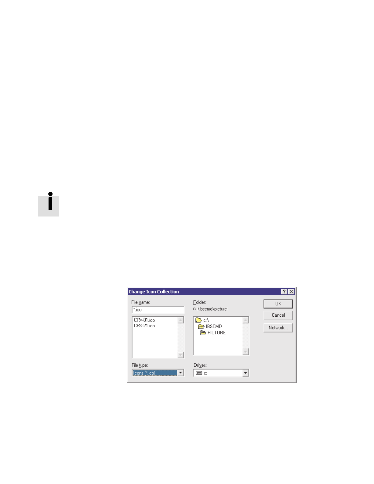
9. Representation:
You can adapt the representation of the CPX terminal
individually in the CMD software. However, this is not
absolutely necessary for commissioning.
By actuating the “Presentation” button you can open a
dialogue window in which you can set a specific icon for
the CPX terminal.
The specific icons for CPX terminals can be found online
www.festo.com/Fieldbus Firmware and drivers.
•
Copy the file “CPX-21.ico” into the CMD directory
\PICTURE\.
•
Actuate the “Select ...” button in the “Presentation”
dialogue window.
•
Select the entry “Icons (*.ico)” under “File type”.
Fig. 2/11: Dialogue window “Change Icon Collection”
2-26
Festo P.BE-CPX-FB20/21-E N en 1202a

2. Commissioning
•
Select the file “CPX-01.ico”.
Fig. 2/12: Dialogue window “Presentation” for selecting an
icon
•
Accept your selection with OK.
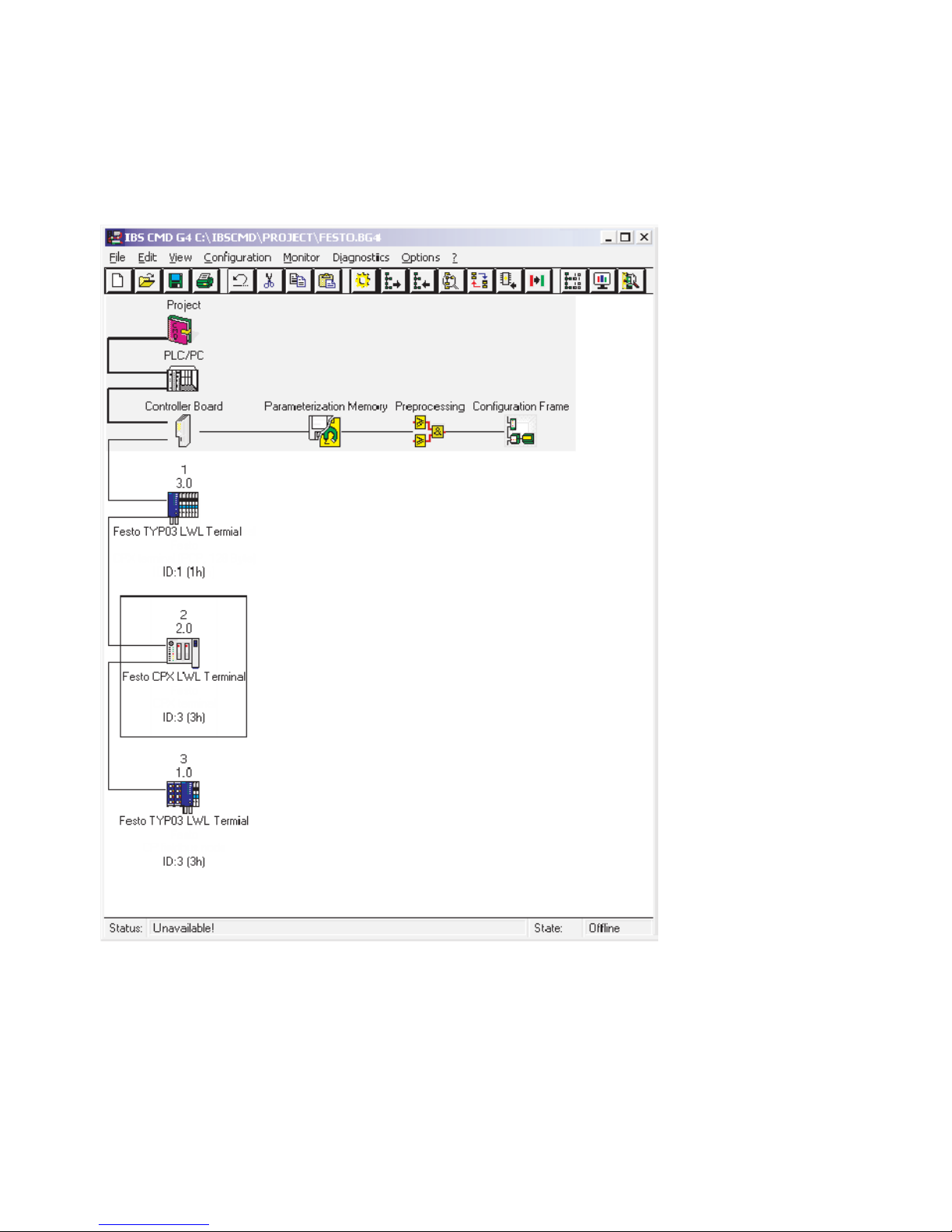
When all entries have been made, the CPX terminal will be
integrated in your bus structure as follows (example):
Festo P.BE-CPX-FB20/21-EN en 1202a
2-27
2. Commissioning
Fig. 2/13: Example – inserted CPX terminal
2-28
Festo P.BE-CPX-FB20/21-E N en 1202a

2. Commissioning
2.1.7 Bus configuration without CMD software
Logical addressing
In the case of the bus configuration without CMD software,
the following specifications must be known or ascertained for
each bus slave. Configure the CPX terminal as follows:
•
ID code (Ident. code)
– CPX terminal only with outputs
1)
:IDcode1
D
– CPX terminal only with inputs:IDcode2
D
– CPX terminal with inputs an d outputs1):IDcode3
1)
Valve coils and/or electric outputs
•
Process data channel:
– Calculate the number of I/Os per valve terminal.
The number of inputs and/or outputs must be
rounded up to the next word limit.
If the number of input bits differs from the number of
output bits, the greater number is in each case
decisive for the entry of the process data channel bits.
– Please note the following:
Diagnostics mode 3 occupies an additional 16 inputs.
Diagnostics mode 2 and 4 occupy an additional
32 inputs.
– Assign logical IN and OUT addresses to each slave.
D
Festo P.BE-CPX-FB20/21-EN en 1202a
2-29

2. Commissioning
2.1.8 Process data entry via the CMD software
The CMD software offers as from version 4 the possibility of
assigning any input/output in the PLC/IPC bit-by-bit to each
input/output of a CPX terminal within the configured address
range. Proceed as follows:
1. Insert a CPX terminal into your bus structure (necessary
steps see section 2.1.6 “Bus configuration with the CMD
software”).
2. Select the command “Process Data” in the context menu
of the CPX terminal.
2-30
Festo P.BE-CPX-FB20/21-E N en 1202a

2. Commissioning
Fig. 2/14: Open the dialogue window “Process Data”
Festo P.BE-CPX-FB20/21-EN en 1202a
2-31

2. Commissioning
You can define the I/O addresses in the following dialogue
window. In this way you can adapt the I/Os of the CPX
terminal to the PLC used. The following diagram shows the
byte-by-byte assignment for a Siemens S7:
Fig. 2/15: Enter process data – Example for “Siemens mode”
2-32
Festo P.BE-CPX-FB20/21-E N en 1202a

2. Commissioning
If necessary, swap the high byte and the low byte (byte swap).
Note
You can select the data format in two ways:
EitherviaDILswitch1.3(seeTab.1/2)orviatheCMD
software.
Selection of data format via the CMD software:
InordertocorrectthebyteassignmentintheSiemensand
Standard modes, it will suffice to assign the appropriate
I/O address to each byte.
Individual I/O assignment at bit level is only necessary in
rare cases.
The following dialogue window shows the entries required for
swappingtheassignmentofthehighbyteandthelowbyte
(example: byte swap for “Standard mode”).
Fig. 2/16: Modification of the I/O assignment (byte swap) – Example for “Standard mode”
Festo P.BE-CPX-FB20/21-EN en 1202a
2-33

2. Commissioning
2.2 Parameterisation
You can set the reaction of the CPX terminal as well as the
reaction of individual modules and channels by
parameterisation. A distinction is made between the following
parameterisations:
– System parameterisation, e.g.: switching off fault
messages, etc.
– Module parameterisation (module and channel-specific),
e. g.: monitoring, settings in the event of errors, settings
for Forcing.
Parameters of the CPX terminal
A description of the functions of the individual parameters
canbefoundintheCPXsystemmanual.
Which module parameters are available for the various
modules can be found in the manual for the relevant module
(e.g. manual for CPX I/O modules (P.BE-CPX-EA-...)).
2-34
Festo P.BE-CPX-FB20/21-E N en 1202a

2. Commissioning
Prerequisites for parameterisation
With the system parameter “System start” you can influence
the starting reaction. If possible select the setting “System
start with default parametrisation and current CPX expansion”.
The desired parameterisation can then be carried out in the
initialisation phase or user-controlled.
Note
The CPX terminal can only be parameterised if the system
parameter “System start” has the setting “System start
with default parametrisation and current CPX expansion”.
If the M LED lights up permanently after the system start,
then “System start with saved parametrisation and saved CPX
expansion” is set. In this case, no other parameterisation can
be carried out.
Caution
In the case of CPX terminals on which the M LED lights up
permanently, the parameterisation will not be restored
automatically by the higher-order system if the CPX
terminal is replaced during servicing. In these cases, check
before replacement to see which settings are required and
carry out these settings.
Festo P.BE-CPX-FB20/21-EN en 1202a
2-35

2. Commissioning
2.2.1 Parameterisation concepts
You can parameterise a CPX terminal with the bus node CPXFB20/21 with the help of the handheld device (see following
table).
The handheld is required for all parameterisation methods.
Method
Handheld Parameterisation is
Description Advantages Disadvantages
carried out via
menu-guided entries
with the handheld.
Tab. 2/7: Parameterisation concepts
Further instructions on the procedure for parameterisation
can be found in the sections which follow.
– Very user-friendly
parameterisation via
menu-guidance
(plain text).
– Parameterisation is
saved locally in the
CPX terminal and is
lost if the CPX terminal
is replaced.
– Access via remote
maintenance is not
possible.
2-36
Festo P.BE-CPX-FB20/21-E N en 1202a

2. Commissioning
Parameterisation processes
After Power ON, the CPX terminal can be parameterised via
the handheld.
Note
The last parameterisation received in the CPX terminal is
always valid.
The CPX terminal can only be parameterised if the system
parameter “System start” has the setting “System start with
default parametrisation and current CPX expansion”.
In this case, the standard parameter settings are valid in the
CPX terminal after Power ON.
Note
If the system parameter “System start” has the setting
“System start with saved parametrisation and saved CPX
expansion”, modified parameter settings in the CPX terminal will become valid immediately after Power ON.
Festo P.BE-CPX-FB20/21-EN en 1202a
2-37

2. Commissioning
2.3 Commissioning the CPX terminal on the Interbus
In order to avoid faults (e.g. configuration and parameterisation faults) during commissioning:
•
Please observe the general commissioning instructions in
the CPX system manual.
•
Check the DIL switch settings before using and replacing
CPX terminals.
•
Note the instructions for switching on the power supply in
section 2.1.5.
•
Check the configured address range (process data and
assigned input and output bytes). If necessary, test the
I/Os.
•
Check the address assignment of the I/Os on the
CPX terminal. In order to do this, you can, if necessary,
force the I/Os (see CPX system manual).
•
Make sure that the desired parameterisation of the
CPX terminal in the initialization phase or after fieldbus
interruptions is carried out by the module. This is to ensure that if the CPX terminal is replaced, the new terminal
will also be operated with the desired parameter settings.
•
Carry out spot checks if necessary to check parameterisation with the handheld.
2-38
Festo P.BE-CPX-FB20/21-E N en 1202a

2. Commissioning
2.3.1 Fail safe
The CPX terminal supports special Fail Safe parameterisation.
System-specific I/O states can therefore be defined in the
event of a fault.
Information on Fail Safe parameterisation can be found in the
CPX system manual.
Note
In order to maintain defined I/O states in the event of a
fault, the Sysfail evaluation of the Interbus master must be
activated.
With the Sysfail evaluation in the Interbus master, it is ensured that if the PLC (CPU) stops or has a fault, the exchange
of process data between the CPU and the Interbus module
will be synchronized.
This is to prevent 0-signals from being incorrectly transmitted
via the Interbus. Otherwise, useful Fail Safe treatment or programming would not be possible.
Festo P.BE-CPX-FB20/21-EN en 1202a
2-39

2. Commissioning
2-40
Festo P.BE-CPX-FB20/21-E N en 1202a

Diagnostics and e rror h andling
Chapter 3
Diagnostics and error handling
Festo P.BE-CPX-FB20/21-EN en 1202a
3-1

3. Diagnostics and error handling
Contents
3. Diagnostics and error handling 3-1...................................
3.1 Summary of diagnostics options 3-2...................................
3.2 Diagnostics via LEDs 3-3............................................
3.2.1 Normal operating status 3-5..................................
3.2.2 CPX-specific LEDs 3-6.......................................
3.2.3 Interbus-specific LEDs 3-9....................................
3.3 Diagnosis via Interbus 3-12...........................................
3.3.1 Diagnostics mode 2 … 4 (system diagnostics) 3-12.................
3.3.2 Peripheral fault (PF) 3-20......................................
3.4 Error handling 3-21..................................................
3-2
Festo P.BE-CPX-FB20/21-E N en 1202a
3. Diagnostics and error handling
3.1 Summary of diagnostics options
The CPX terminal provides extensive and user-friendly
possibilities for diagnostics and error handling. The following
possibilities are available depending on the configuration:
Diagnostics
Brief description Advantages Detailed
option
LED display The LEDs show directly configuration
faults, hardware faults, bus faults, etc.
Diagnostics
modes 2, 3
and 4
Diagnostics
via the
handheld
1)
Please note that during diagnostics via the handheld the allocated inputs of diagnostic
modes 2 ... 4 are not displayed.
1)
Depending on diagnostic mode (2, 3,
or 4) the diagnostic bytes can be
allocatedatthebeginningorendofthe
input image table.
Diagnostic information can be shown on
the handheld in a user-friendly manner
by means of menus.
Fast “on-the-spot”
recognition of
errors
Valve diagnosis Section 3.3.1
Fast “on-the-spot”
recognition of
faults
Tab. 3/1: Diagnostics options
description
Section 3.2
Description for the
handheld
Festo P.BE-CPX-FB20/21-EN en 1202a
Peripheral fault (PF)
If a fault is recognized by the CPX terminal, a peripheral fault
will be triggered, transmitted to the module and displayed
there (see section 3.3.2).
Note
Note that the diagnostic information displayed can be dependent on the DIL switch settings on the bus node, as
well as on the parameterisation of the CPX terminal.
3-3

3. Diagnostics and error handling
3.2 Diagnostics via LEDs
LEDs for the diagnostics of the CPX terminal are available on
the bus node as well as on the individual modules.
The meaning of the L EDs on the electric modules can be
found in the manual for the relevant module.
LEDs on the bus node CPX-M-FB20/CPX-M-FB21
The LEDs on the cover indicate the operating status of the
CPX bus node.
1
Interbus-specific
LEDs:
– UL (green)
– RC (green)
– BA (green)
– RD (yellow)
– FO1 (yellow)
– FO2 (yellow)
2
CPX-specific
LEDs:
–SF(red)
– US1 (green)
– US2 (green)
– M (yellow)
Fig. 3/1: LEDs on the CPX bus node CPX-M-FB20/CPX-M-FB21
1
2
3-4
Festo P.BE-CPX-FB20/21-E N en 1202a

3. Diagnostics and error handling
LED Meaning
UL Interbus diagnostics
RC Remotebus check
BA Bus active
RD Remotebus disable
FO1 Diagnostics, incoming fibre optic cable length
FO2 Diagnostics, outgoing fibre optic cable length
SF System fault
US1 Diagnosis of the logic voltage supply
(electronics/sensors)
US2 Diagnosis of the load voltage supply
(outputs/valves)
M Parameterisation modified/forcing active
Tab. 3/2: Meaning of the LEDs
Possible LED displays on the node for the operating status of
the valve terminal are shown in the table below.
Festo P.BE-CPX-FB20/21-EN en 1202a
3-5

3. Diagnostics and error handling
The LEDs are shown in their various states as follows:
lights up; flashes; off
3.2.1 Normal operating status
In the normal operating status all green LEDs light up. The red
and yellow LEDs do not light up.
LED display
All green LEDs light up:
–UL
–RC
–BA
–US1
–US2
Red and yellow LEDs
do not light up:
–RD
–FO1
–FO2
–SF
–M
Operating
status
Normal
3-6
Festo P.BE-CPX-FB20/21-E N en 1202a

3. Diagnostics and error handling
3.2.2 CPX-specific LEDs
US1 – Power sensor/logic supply
LED (green) Procedure Status Meaning/error handling
LED
illuminates
LED flashes
LED is off
ON
OFF
ON
OFF
ON
OFF
No error. Operating
voltage/sensor supply
applied
Operating voltage/sensor
supply outside the
tolerance range
The operating
voltage/sensor supply is
not applied
–
Eliminate undervoltage
Check the operating voltage
connection of the electronics
US2 – Power load supply (outputs/valves)
LED (green) Procedure Status Meaning/error handling
LED
illuminates
LED flashes
ON
OFF
ON
OFF
No error. Load voltage
applied
Load voltage at the system
supply or additional supply
outside the tolerance
range
None
Eliminate undervoltage
ON
OFF
LED is off
Festo P.BE-CPX-FB20/21-EN en 1202a
Load voltage is not applied. Check load voltage connection
3-7

3. Diagnostics and error handling
SF (System Failure) – System fault
LED (red) Sequence
1)
Status Meaning/error handling
ON
OFF
No error –
LED is off
ON
OFF
Simple fault/information
(error class 1)
See description of error numbers in
the CPX system manual
LED flashes
ON
OFF
Error
(error class 2)
LED flashes
ON
OFF
Serious fault
(error class 3)
LED flashes
1)
The system fault LED flashes depending on the class of fault which has occurred.
Fault class 1 (simple fault): 1 * flash, pause
Fault class 2 (fault): 2 * flash twice, pause
Fault class 3 (serious fault): 3 * flash three times, pause
3-8
Festo P.BE-CPX-FB20/21-E N en 1202a

3. Diagnostics and error handling
M (Modify) – Parameterisation modified or forcing active
LED (yellow) Procedure Status Meaning/error handling
ON
OFF
LED is off
System start with default
parameterisation (factory
setting) and current CPX
equipment status is set;
None
external parameterisation
is possible (pre-setting).
LED
illuminates
ON
OFF
System start with saved
parameterisation and
saved CPX expansion has
been set; parameters and
CPX equipment status are
saved remanently; external
parameterisation is
blocked
1)
Be careful when replacing
CPX valve terminals with saved
parameterisation.
With these CPX valve terminals,
parameterisation is not carried out
automatically by the higher-order
PLC/IPC when the terminal is
replaced. In these cases check before
replacing to see which settings are
required and, if necessary, carry out
these settings.
ON
OFF
Force is ac tive
LED flashes
1)
The display of the Force function (LED flashes) has precedence over the display of the setting for
1)
The force function is enabled
(see system parameter force mode;
function no. 4402).
System start (LED lights up).
Festo P.BE-CPX-FB20/21-EN en 1202a
The LED M is intended for several functions (see also under
Interbus-specific L EDs). The status which is shown takes
place in the following sequence:
1. Force active
2. Parameters saved remanently
3-9

3. Diagnostics and error handling
3.2.3 Interbus-specific LEDs
UL (U Load) – Logic supply for bus interface
LED (green) Procedure Status Meaning/error handling
LED
ON
OFF
No error. Logic voltage
applied
–
illuminates
ON
OFF
The logic supply for the bus
interface is not present
Servicing required, if necessary replace bus node
LED is off
RC (Remote Bus Check) – Fieldbus connection
LED (green) Procedure Status Meaning/error handling
LED
illuminates
LED is off
ON
OFF
ON
OFF
Incoming remote bus
connection OK
Incoming remote bus
connection faulty
–
Check incoming fieldbus connection.
BA (Bus Active) – Remote bus active
LED (green) Procedure Status Meaning/error handling
ON
LED
OFF
illuminates
ON
OFF
LED flashes
ON
OFF
LED is off
3-10
Data transmission on
Interbus active, Interbus to
RUN
– No data transmission on
the Interbus
– Module
initiates ID cycles
No data transmission on
the Interbus
–
• Eliminate bus fault
• Reset module
• Acknowledge e rror
• Star t data transmission
Module not in status “Run”.
Festo P.BE-CPX-FB20/21-E N en 1202a

3. Diagnostics and error handling
RD (Remote Bus Disable) – Remote bus switched off
LED (yellow) Procedure Status Meaning/error handling
LED
illuminates
ON
OFF
ON
OFF
– Continuing interface
switched off.
– Data transmission on
the Interbus interrupted.
Normal operation. –
• Star t data transmission.
• Check slaves on continuing
interface.
LED is off
FO1 (Fibre Optic 1) – Diagnostics of incoming FOC length
LED (yellow) Procedure Status Meaning/error handling
– LED flickers
–
ON
OFF
– After initialization:
Incoming fibre optic
cable length bad or the
system reserves are not
reached or the
previously installed
module does not
support fibre optic cable
control.
– In the “Bus active”
status: Incoming fibre
optic cable length bad or
the system reserves are
not reached.
Check system/fibre optic cable
transmission
ON
OFF
LED is off
Festo P.BE-CPX-FB20/21-EN en 1202a
FOC-length OK –
3-11

3. Diagnostics and error handling
FO2 (Fibre Optic 2) – Diagnostics of outgoing FOC length
LED (yellow) Procedure Status Meaning/error handling
LED flickers
LED is off
ON
OFF
ON
OFF
– After initialization:
Outgoing fibre optic
cable length bad or the
system reserves are not
reached or the next
module does not
support fibre optic cable
control.
– In the “Bus active”
status: Outgoing fibre
optic cable length bad or
the system reserves are
not reached.
FOC-length OK –
Check system/fibre optic cable
transmission
3-12
Festo P.BE-CPX-FB20/21-E N en 1202a

3. Diagnostics and error handling
3.3 Diagnosis via Interbus
The CPX terminal enables diagnosis via the Interbus. The
following diagnostic possibilities are suppor ted here:
– Diagnostics mode 2 … 4 (system diagnostics)
– Peripheral errors
3.3.1 Diagnostics mode 2 … 4 (system diagnostics)
The bus node CPX-M-FB20/21 has four diagnostic modes,
which are activated via DIL switches 5 and 6 (see Tab. 1/4).
The following diagnostic modes are available:
– Diagnostic mode 1: No diagnosis
– Diagnostic mode 2: Diagnosis occupies 4 bytes
at the start of the image table
– Diagnostic mode 3: Diagnosis occupies 2 bytes at the end
of the image table
– Diagnostic mode 4: Diagnosis occupies 4 bytes at the end
of the image table
Examples of diagnostic modes in the image table:
Abbreviations in Tab. 3/3 … Tab. 3/5:
Abbrevia tion Meaning
Coil Valve solenoid coil
Festo P.BE-CPX-FB20/21-EN en 1202a
DI-Modul Digitales Eingangsmodul
DO module Digital output module
3-13

3. Diagnostics and error handling
Diagnostic mode 2
4 byte diagnostics at the start of the process image of the
inputs with 32 solenoid coils, 4 input modules (every 16
channels), 2 output modules (every 4 channels)
Byte
0 General diagnostics 1
1 Val ve dia g n os tics 1
2 General diagnostics 2
3 Val ve dia g n os tics 2
4 DI module 1 (channel 0 ... 7) DO module 1 (channel 0 ... 3)
5 DI module 1 (channel 8 ... 15)
6 DI module 2 (channel 0 ... 7)
7 DI module 2 (channel 8 ... 15)
8 DI module 3 (channel 0 ... 7)
9 DI module 3 (channel 8 ... 15)
10 DI module 4 (channel 0 ... 7)
Input data Output data
1)
1)
1)
1)
Coil 0 … 7
Coil 8 … 15
Coil 16 … 23
Coil 24 … 31
DO module 2 (channel 4 ... 7)
11 DI module 4 (channel 8 ... 15)
1) See Tab. 3/6 to Tab. 3/9
Tab. 3/3: Example of a process image with diagnostic mode 2
3-14
Festo P.BE-CPX-FB20/21-E N en 1202a

3. Diagnostics and error handling
Diagnostic mode 3
2bytediagnosticsattheendoftheprocessimageoftheinputs with 16 solenoid coils, 4 input modules (every 16 channels), 4 output modules (every 4 channels)
Byte
0 DI module 1 (channel 0 ... 7) Coil 0 … 7
1 DI module 1 (channel 8 ... 15) Coil 8 … 15
2 DI module 2 (channel 0 ... 7) DO module 1 (channel 0 ... 3)
3 DI module 2 (channel 8 ... 15) DO module 3 (c hannel 0 ... 3)
4 DI module 3 (channel 0 ... 7)
5 DI module 3 (channel 8 ... 15)
6 DI module 4 (channel 0 ... 7)
7 DI module 4 (channel 8 ... 15)
8 General diagnostics 1
9 General diagnostics 2
10
Input data Output data
DO module 2 (channel 4 ... 7)
DO module 4 (channel 4 ... 7)
1)
1)
11
1) See Tab. 3/6 to Tab. 3/9
Tab. 3/4: Example of a process image with diagnostic mode 3
Festo P.BE-CPX-FB20/21-EN en 1202a
3-15

3. Diagnostics and error handling
Diagnostic mode 4
4 byte diagnostics at the end of the process image of the inputs with 32 solenoid coils, 4 input modules (every 16 channels), 6 output modules (every 4 channels)
Byte
0 DI module 1 (channel 0 ... 7) Coil 0 … 7
1 DI module 1 (channel 8 ... 15) Coil 8 … 15
2 DI module 2 (channel 0 ... 7) Coil 16 … 23
3 DI module 2 (channel 8 ... 15) Coil 24 … 31
4 DI module 3 (channel 0 ... 7) DO module 1 (channel 0 ... 3)
5 DI module 3 (channel 8 ... 15) DO module 3 (c hannel 0 ... 3)
6 DI module 4 (channel 0 ... 7) DO module 5 (channel 0 ... 3)
7 DI module 4 (channel 8 ... 15)
8 General diagnostics 1
9 General diagnostics 2
Input data Output data
DO module 2 (channel 4 ... 7)
DO module 4 (channel 4 ... 7)
DO module 6 (channel 4 ... 7)
1)
1)
10 Valve d i agnostic s 1
11 Valve d i agnostic s 2
1) See Tab. 3/6 to Tab. 3/9
1)
1)
Tab. 3/5: Example of a process image with diagnostic mode 4
3-16
Festo P.BE-CPX-FB20/21-E N en 1202a
 Loading...