

Page 1
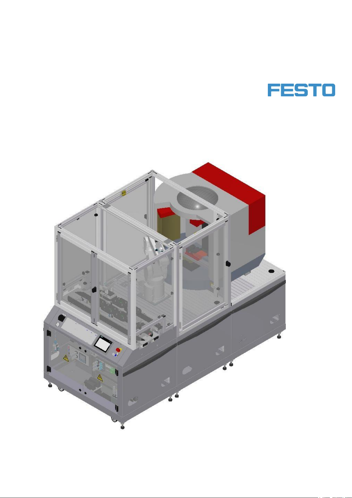
CP Factory®
Manual
Robot feeding for mill
Festo Didactic
CP Factory
12/2018
Page 2

Order number:
Status: 02/2018
Layout: 02/2018, Schober, Weiss
File Name: CP-F-RASS-KUKA-GB-A001.doc
© Festo Didactic SE, 73770 Denkendorf, Germany, 2018
Internet: www.festo-didactic.com
E-Mail: [email protected]
Intended use
This installation was developed and manufactured only for the use in basic and further training in
the fields of automation and communications. The training company and/or the training staff must
ensure that the trainees observe the safety precautions described in the accompanying manuals.
Furthermore this manual describes setup and possible uses of the singular stations. It contains all
information and data required for commissioning, maintenance and operation.
Festo Didactic accepts no liability for injury or harm to trainees, the training company and/or any
third parties which may occur when the installation is used beyond a genuine training situation,
except Festo Didactic has caused such injury or harm intentionally or by grossly negligence.
Experimenting on CP Factory / CP Lab systems with hazardous live voltage is not allowed.
This manual, all text and illustrations included, is protected by copyright. Any utilization outside the
limits of the copyright law and other than training purposes are not permissible without our definite
approval. This applies in particular to reproductions, operations, translations, micro filming and the
storing and processing into electronic systems. Distribution of this documentation, as well as
reproduction, use and spread of its contents is prohibited, insofar not permitted explicitly. Offences
are liable to compensation. All rights reserved, especially the right to execute registrations
concerning patents, designs for use and patterns.
Intended use also comprises observing all instructions in the operating manual and carrying out the
inspection and maintenance works.
2 © Festo Didactic CP Factory ° Robot feeding for mill
Page 3

Content
Content
1 General safety instructions __________________________________________________________________ 6
1.1 Pictographs ___________________________________________________________________________ 7
1.2 Safety terminal sockets _________________________________________________________________ 8
1.3 Information for the electrical connection of the systems ______________________________________ 8
1.4 Handling the system ___________________________________________________________________ 9
1.4.1 Dangers when using the machine _____________________________________________________ 9
1.4.2 Safety precautions in normal operation ________________________________________________ 9
1.4.3 Dangers caused by electrical energy ___________________________________________________ 9
1.4.4 Dangers caused by pneumatic energy _________________________________________________ 9
1.4.5 Maintenance and fault clearance______________________________________________________ 9
1.4.6 Organizational measures ____________________________________________________________ 9
1.5 Staff ________________________________________________________________________________ 10
1.5.1 Instructions regarding the staff ______________________________________________________ 10
1.5.2 Training operations ________________________________________________________________ 10
1.5.3 Beyond training operations _________________________________________________________ 10
1.6 Commitment of the operator ____________________________________________________________ 10
1.7 Commitment of the trainees ____________________________________________________________ 10
2 Introduction _____________________________________________________________________________ 11
2.1 Warranty and liability __________________________________________________________________ 11
2.2 Important information _________________________________________________________________ 11
2.3 Resources ___________________________________________________________________________ 12
3 Design and function _______________________________________________________________________ 15
3.1 Transport ____________________________________________________________________________ 15
3.2 Set up ______________________________________________________________________________ 15
3.2.1 General notes ____________________________________________________________________ 15
3.3 Robot feeding for mill __________________________________________________________________ 16
3.3.1 General __________________________________________________________________________ 16
3.4 Mechanical structure __________________________________________________________________ 21
3.4.1 Supply of the Robot feeding for mill __________________________________________________ 25
3.5 Electrical set up ______________________________________________________________________ 27
3.5.1 Siemens PLC _____________________________________________________________________ 29
3.5.2 Cabling chart _____________________________________________________________________ 31
3.5.3 Emergency stop structure __________________________________________________________ 32
3.5.4 Emergency-stop with central control __________________________________________________ 35
3.6 Commissioning _______________________________________________________________________ 36
3.6.1 Pneumatic commissioning __________________________________________________________ 36
3.6.2 Electrical commissioning ___________________________________________________________ 36
3.7 Commissioning _______________________________________________________________________ 37
3.7.1 Pneumatic commissioning __________________________________________________________ 37
3.7.2 Electrical commissioning ___________________________________________________________ 37
3.8 Adjusting the sensors _________________________________________________________________ 38
3.8.1 Proximity switch (stopper Identsensor) _______________________________________________ 38
3.8.2 Proximity switch (stopper cylinder) ___________________________________________________ 40
3.9 Adjusting the one-way flow control valves _________________________________________________ 42
© Festo Didactic CP Factory ° Robot feeding for mill 3
Page 4

Content
3.10 Visual inspection ____________________________________________________________________ 43
3.11 Starting up _________________________________________________________________________ 43
4 Operation _______________________________________________________________________________ 44
4.1 General notes on operation _____________________________________________________________ 44
4.1.1 Handling regulations ______________________________________________________________ 44
4.1.2 Operating regulations ______________________________________________________________ 44
4.2 The control units of the robot feeding for mill ______________________________________________ 45
4.2.1 Touch Panel ______________________________________________________________________ 46
4.3 Sequence description of robot feeding for mill _____________________________________________ 47
4.4 Sequence description of the Basic Module ByPass _________________________________________ 49
4.4.1 CP Factory Loading Robot (Mill and Turn) ______________________________________________ 54
4.4.2 Switch on robot ___________________________________________________________________ 57
4.5 Operating modes _____________________________________________________________________ 58
4.5.1 Automatic operation _______________________________________________________________ 58
4.5.2 Setup mode ______________________________________________________________________ 58
4.6 Operating the HMi Touchpanel __________________________________________________________ 58
4.6.1 Menu architecture from Panel _______________________________________________________ 59
4.6.2 Menu navigation robot feeding for mill ________________________________________________ 60
4.6.3 Display operation modus ___________________________________________________________ 62
4.6.4 Operation mode Home _____________________________________________________________ 63
4.6.5 Operating mode Setup _____________________________________________________________ 69
4.6.6 Operation mode Parameters ________________________________________________________ 76
4.6.7 Operation mode System - settings ___________________________________________________ 80
4.7 Automatic operation __________________________________________________________________ 81
4.7.1 Start automatic ___________________________________________________________________ 81
4.7.2 Stop automatic ___________________________________________________________________ 83
4.8 Writing on the RFID tag manually ________________________________________________________ 84
4.8.1 Pallet carriers ____________________________________________________________________ 84
4.8.2 Boxes ___________________________________________________________________________ 86
4.8.3 Parameter CP Factory feeding robot and mill ___________________________________________ 87
5 Components _____________________________________________________________________________ 88
5.1 Mitsubishi Robot RV-4FL _______________________________________________________________ 88
5.1.1 Drive Unit CR750-D ________________________________________________________________ 89
5.1.2 Teach pendant R32TB ______________________________________________________________ 91
5.1.3 Teachpendant R56TB ______________________________________________________________ 92
5.1.4 Set up ___________________________________________________________________________ 93
5.1.5 Interface Drive Unit ________________________________________________________________ 96
5.1.6 Parameter ______________________________________________________________________ 100
5.1.7 Main tasks/Programmes __________________________________________________________ 101
5.1.8 Return message _________________________________________________________________ 101
5.1.9 Further information to robot _______________________________________________________ 101
5.2 Robot positions _____________________________________________________________________ 102
5.3 Electrical components ________________________________________________________________ 103
5.3.1 2 Quadrant Controller _____________________________________________________________ 103
5.3.2 Controller Siemens _______________________________________________________________ 106
5.3.3 Controller Festo CECC _____________________________________________________________ 107
5.3.4 Turck Interface___________________________________________________________________ 108
4 © Festo Didactic CP Factory ° Robot feeding for mill
Page 5

Content
5.3.5 Scalance Ethernet Switch __________________________________________________________ 109
5.3.6 RFID with Ethernet _______________________________________________________________ 112
5.3.7 RFID with CanBus ________________________________________________________________ 116
5.3.8 Mini Terminal ____________________________________________________________________ 117
5.3.9 SYS link interface ________________________________________________________________ 121
5.4 Mechanic components ________________________________________________________________ 122
5.4.1 Motor of Conveyor _______________________________________________________________ 122
5.4.2 The stopper unit _________________________________________________________________ 123
5.4.3 Transportation of the basic module _________________________________________________ 125
© Festo Didactic CP Factory ° Robot feeding for mill 5
Page 6

General safety instructions
1 General safety instructions
The laboratory resp. the classroom must be equipped according to the rules of EN 50191:
There must be Emergency Stop equipment in the training area and at least one Emergency Stop outside
the training area.
The training area must be protected against any unauthorized switching-on, e.g. by key-operated
switches.
The training area must be protected by fault current protective circuit (RCD).
– RCD circuit breaker with differential current ≤ 30 mA, type B.
The training area must be protected by overcurrent protections -
– fuses or circuit breakers
The training area must be supervised by a person who is responsible for the activities.
– This person must be a skilled electrician or a person instructed in electrical engineering with the
knowledge of all safety requirements and safety precautions on file.
Any damaged device or faulty device may not be used.
– Any faulty or damaged device has to be blocked and removed from the training area.
General requirements regarding a safe operation of the devices:
Do not lay cables over hot surfaces.
– Hot surfaces are marked with a corresponding warning symbol.
The permitted power loads of cables and devices may not be exceeded.
– Do always compare the current values of the device, the cable and the fuse.
– In case of non-compliance, you have to use a separate upstream fuse as an appropriate overcurrent
protection.
Any device with earth connection must always be grounded.
– If there is a ground connection (green-yellow laboratory socket) available, the connection to the
protective ground must always be effected. The protective ground must always be contacted first
(before voltage) and must only be separated last (after voltage separation).
If not specified differently in the technical data, the device does not have an integrated fuse.
6 © Festo Didactic CP Factory ° Robot feeding for mill
Page 7
General safety instructions
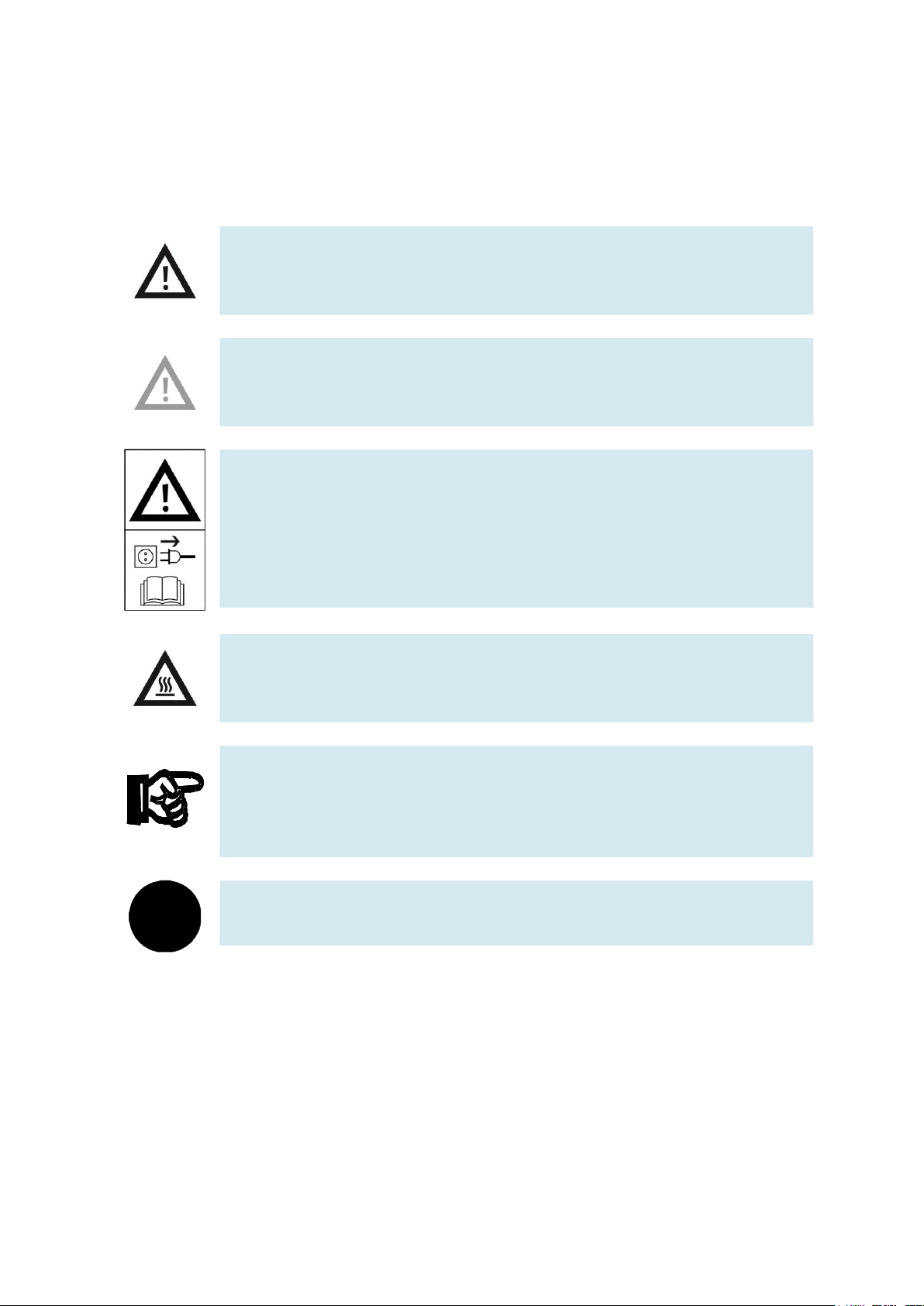
Warning
This means that in case of disregarding the rules, serious personal injury or
material damage may occur.
Caution
This means that in case of disregarding the rules, personal injury or material
damage may occur.
Warning
This means that prior to any mounting, repair, maintenance or cleaning operations,
you have to switch off the device and to disconnect the power plug. Please
observe the manual, especially all information on safety. In case of disregarding,
serious personal injury or material damage may occur.
Warning
This means that you could burn yourself when touching hot surfaces
(temperatures up to 85 ° Celsius).
Important
Here you find important information for an appropriate handling of the machine.
Disregarding this symbol may lead to malfunctions at the machine or in its
surrounding area.
i
Information
This means that you obtain tips for the use and especially useful information.
1.1 Pictographs
This document and the described hardware contain information on possible dangers which may occur when
using the system improperly. The following pictographs are used:
© Festo Didactic CP Factory ° Robot feeding for mill 7
Page 8
General safety instructions
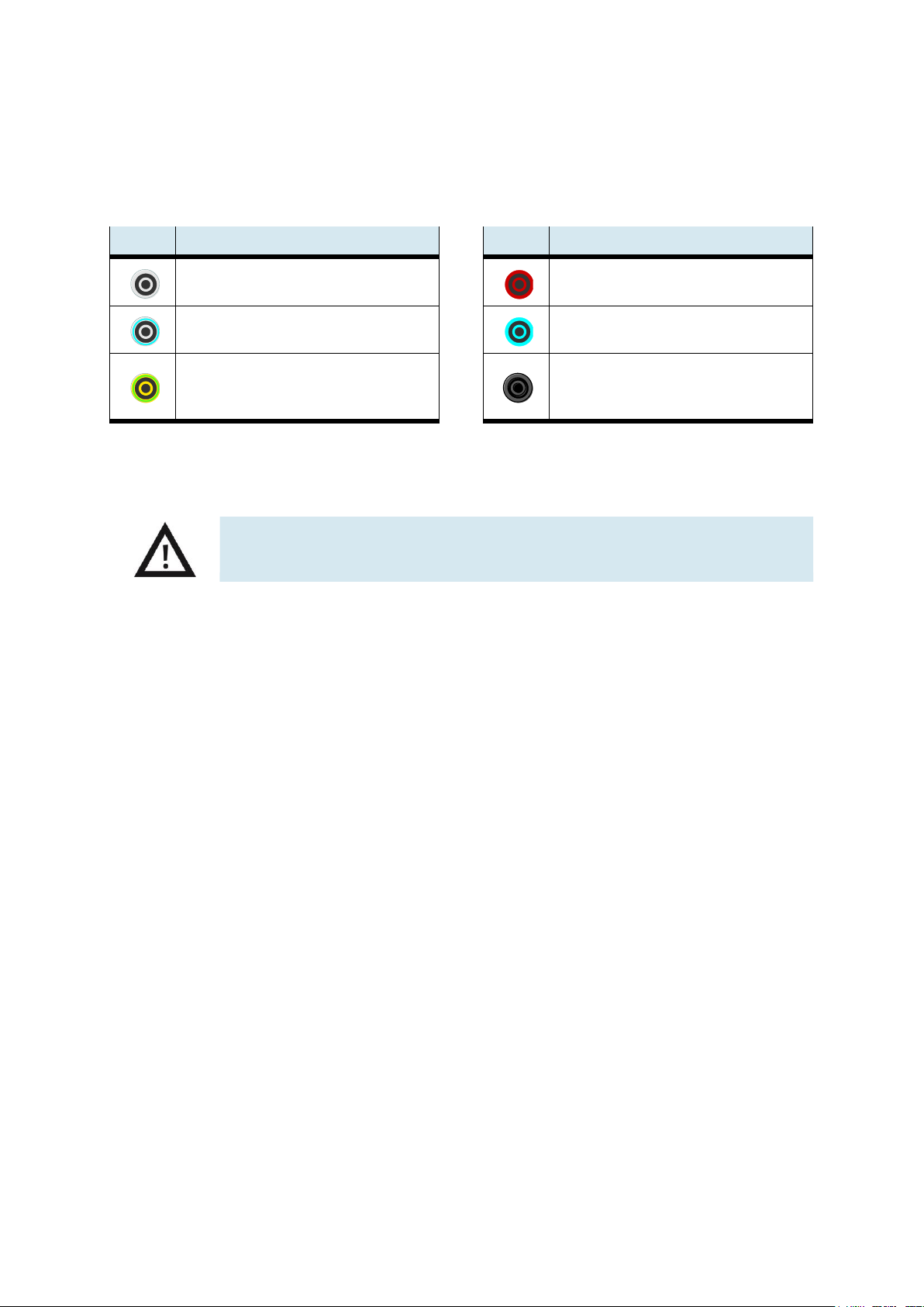
Colour
Meaning
Colour
Meaning
Voltage bigger protective low voltage, e.g.
supply voltage 90 to 400 V AC conductor (grey)
24 V DC
(red)
neutral conductor
(grey/blue)
0 V DC
(blue)
protective earth conductor
(green-yellow)
protective low voltage
signal input/signal output
(black)
Any damaged or faulty safety laboratory cables have to be blocked instantly and to
be removed from the training area.
1.2 Safety terminal sockets
If not specified differently in the technical data, the following colour coding applies for the power and signal
supplies with components of the FESTO Didactic learning system automation and technics.
The specified protection categories and the safety can only been guaranteed when using Festo Didactic
safety laboratory cables.
1.3 Information for the electrical connection of the systems
For the supply of the CP-Factory/ CP-Lab systems, according to the regulations of the EN 60204-1 (VDE
0113-1) part 8.2.8, a supply cable with an additional protective earth conductor is required. Since a leakage
current of > 10mA may flow depending on the expansion, an additional protective earth conductor with
10mm² is required.
See also DIN EN 60204-1.
8 © Festo Didactic CP Factory ° Robot feeding for mill
Page 9
General safety instructions
Any faults which might affect the safety must be eliminated instantly!
1.4 Handling the system
1.4.1 Dangers when using the machine
The system has been constructed in accordance with the state of the art and the recognized safety rules.
Nevertheless, there might occur dangers to life and limb of the user or a third person when used, as well as
negative impact on the system or on other material assets.
You may only use the system:
for the intended use
in excellent condition concerning safety regulations
1.4.2 Safety precautions in normal operation
Please use the system only if all safety devices are fully functional.
Please inspect the system regarding externally discernible damages and the functionality of the safety
devices at least before starting the operation.
Do not touch the running station.
Before any circuit assembly, disassembly or modifications in a circuit:
Switch off the compressed air supply and the power supply.
Observe the general safety regulations: DIN 58126 and VDE 0100.
1.4.3 Dangers caused by electrical energy
After finishing the maintenance works you have to check the safety devices regarding their function.
Only an electrically or electronically trained person is allowed to execute operations on the electrical supply.
The terminal boxes have to be kept close all of the time. Any access is only allowed if supervised by a
training person.
Please do not operate electrical limit switches manually when searching for an error, but use the tools.
Please do only use low voltage 24 VDC.
1.4.4 Dangers caused by pneumatic energy
Tubes coming off due to compressed air may cause injuries. Take away the pressure instantly.
Caution! When switching on the compressed air, the cylinders may drive in or out automatically.
Do not uncouple the tubes when under pressure. Exception: Debugging. In this case, you have to hold the
tube end tight. Do not exceed the permitted working pressure. See also data sheets.
1.4.5 Maintenance and fault clearance
Carry out all prescribed setting and servicing work in due time (see data sheets).
Protect the compressed air and the electrics against an accidental commissioning.
During all maintenance, servicing or repair works, the machine must be disconnected from the power supply
and the compressed air supply, and it must be protected against an unintentional restart.
Please check that all screw connections which have been loosened during the maintenance, servicing or
repair works are firmly seated.
1.4.6 Organizational measures
All existing safety equipment has to be checked regularly.
© Festo Didactic CP Factory ° Robot feeding for mill 9
Page 10

General safety instructions
1.5 Staff
1.5.1 Instructions regarding the staff
Regarding the staff, there are basically two starting situations to be considered.
activities during the training operation
activities not connected with the training operations.
1.5.2 Training operations
The trainees are only allowed to work on the machine if supervised by a skilled person or the instructor.
Any activities concerning fault finding and elimination are controlled by the instructing person.
Safety regulations have to be observed here in particular.
1.5.3 Beyond training operations
All activities concerning maintenance, servicing and repair may only be executed by a person with
sufficiently professional qualifications.
1.6 Commitment of the operator
The operators commit themselves to only allowing the work at the CP-Factory/ CP-Lab to a person who:
is familiar with the principle directions of work safety and accident prevention and has been instructed
in the handling of the CP-Factory / CP-Lab,
has read and understood the safety chapter and the warnings in this manual.
The safety-conscious working of the staff should be checked at regular intervals.
1.7 Commitment of the trainees
Before they start work, all persons in charge of works at the system commit themselves to:
read the safety chapter and the warnings in this manual,
observe the basic principles about work safety and accident prevention.
10 © Festo Didactic CP Factory ° Robot feeding for mill
Page 11

Introduction
2 Introduction
2.1 Warranty and liability
Basically, our “General Terms and Conditions“ apply, which have been made available for the user since the
conclusion of the contract at the latest.
Any warranty and liability claims for personal or material damage will be excluded, if they result from one or
more of the following causes:
any non-intended use of the system
any improper mounting, commissioning, operating and servicing of the system
any operating of the system with faulty safety devices or safety and protective devices which have not
been mounted properly or are not functioning
any disregarding of the information in the manual concerning transport, storage, mounting,
commissioning, operation, servicing and setting-up of the system
any unauthorized constructional alterations on the system
insufficient monitoring of installation parts which are subject to wear and tear
any improperly executed repairs
any major emergencies caused by external influence and force majeure.
Festo Didactic herewith rules out any legal responsibility for damages of the trainee, the training company
and/or a third party which might occur when using the system beyond a genuine training situation, unless
the damage has been caused by Festo Didactic intentionally or due to gross negligence.
2.2 Important information
Knowing the basic safety instructions and the safety rules is a basic prerequisite for the safe handling and
the trouble-free operation of the system.
This manual contains the most important information in order to operate the system in a way that meets the
safety demands.
The safety instructions in particular have to be observed by any person working with the system.
Furthermore all rules and instructions concerning accident prevention applying to the deployment location
have to be observed.
© Festo Didactic CP Factory ° Robot feeding for mill 11
Page 12
Introduction
2.3 Resources
The training equipment of the system consists of several resources. They are used depending on the
process selection.
The following resources are available:
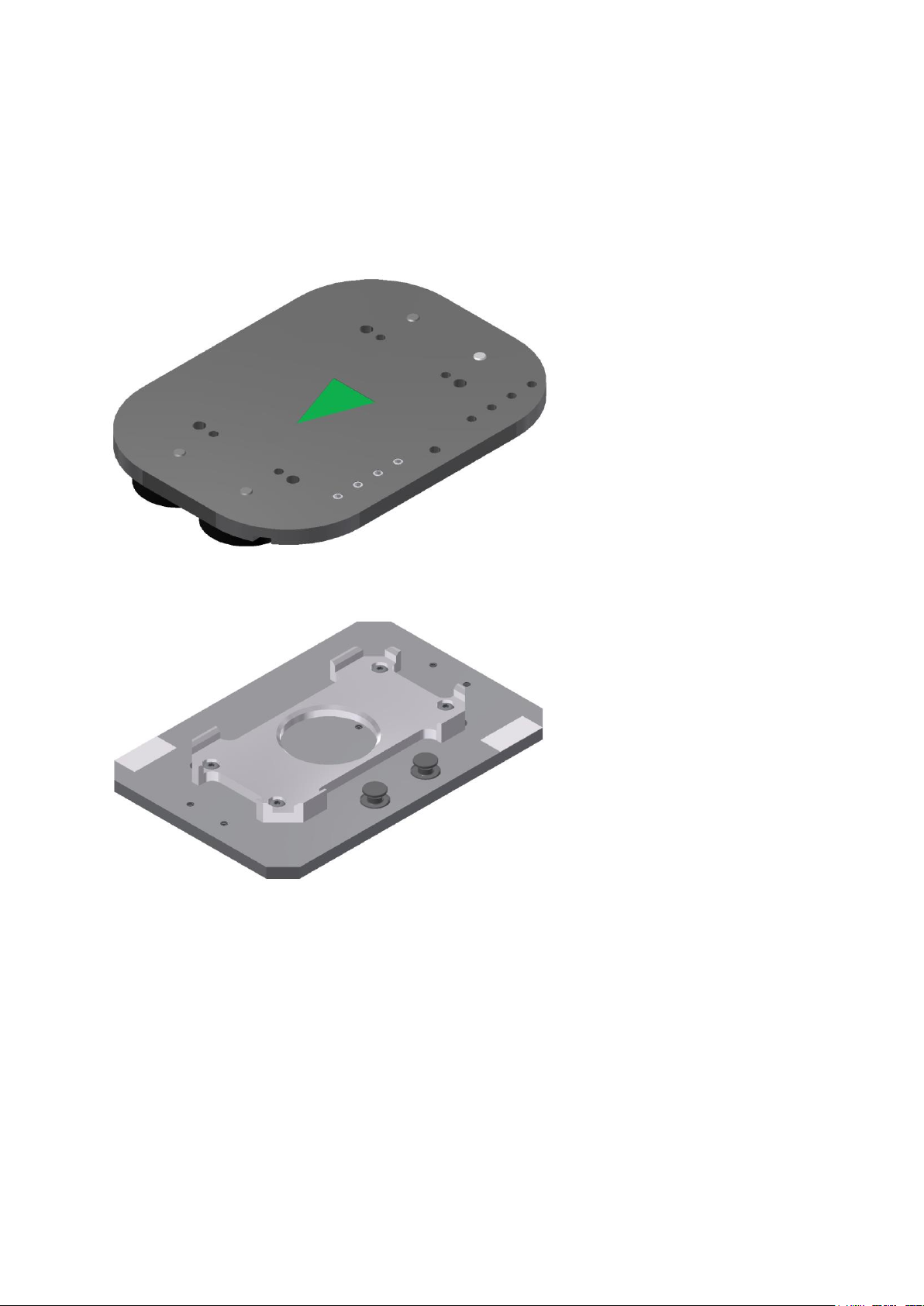
Pallet carrier
These pallet carriers are available for transporting the pallets.
Pallet
These pallets are available for receiving always one workpiece.
12 © Festo Didactic CP Factory ° Robot feeding for mill
Page 13
Introduction
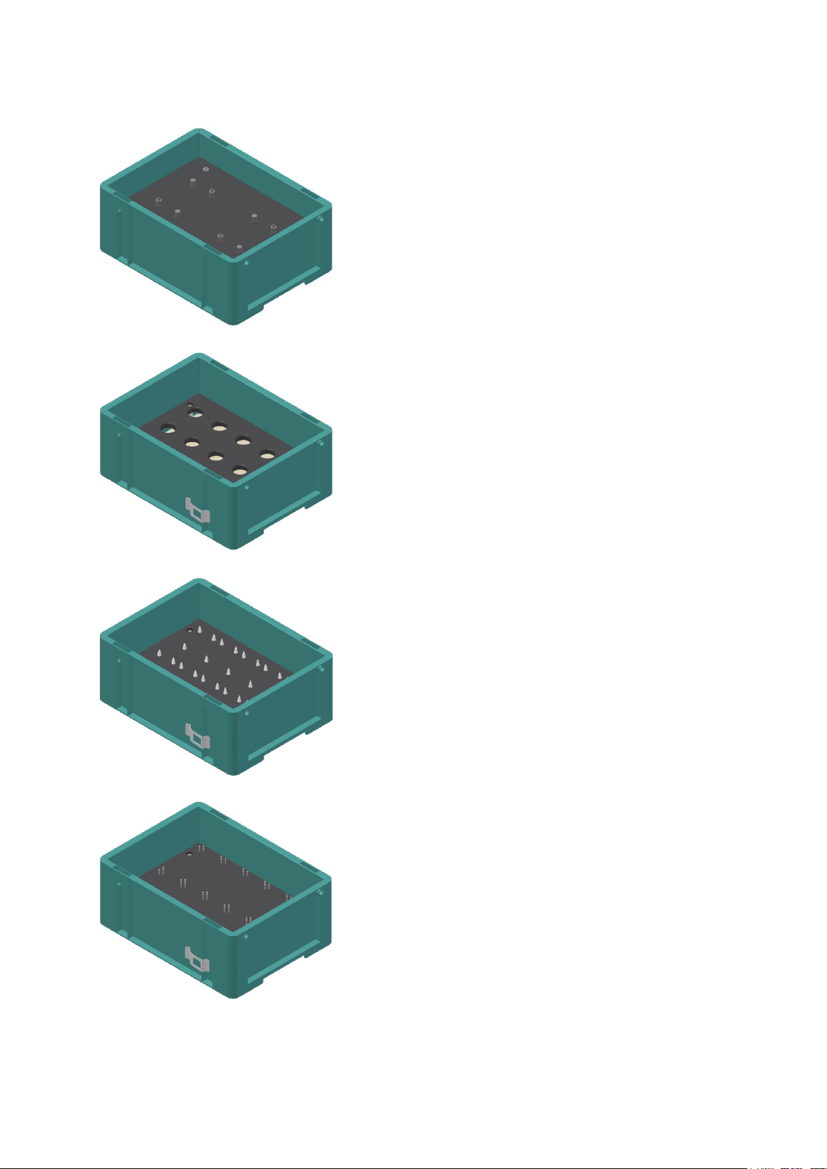
Box with retainer for 2 pallet carriers – Box Partnumber 20
Box with retainer for 15 raw turning pieces – Box Partnumber 26
Box with retainer for 10 PCB´s – Box Partnumber 27
Box with retainer for 10 front/backcovers or assembled workpieces – Box Partnumber 28
© Festo Didactic CP Factory ° Robot feeding for mill 13
Page 14
Introduction
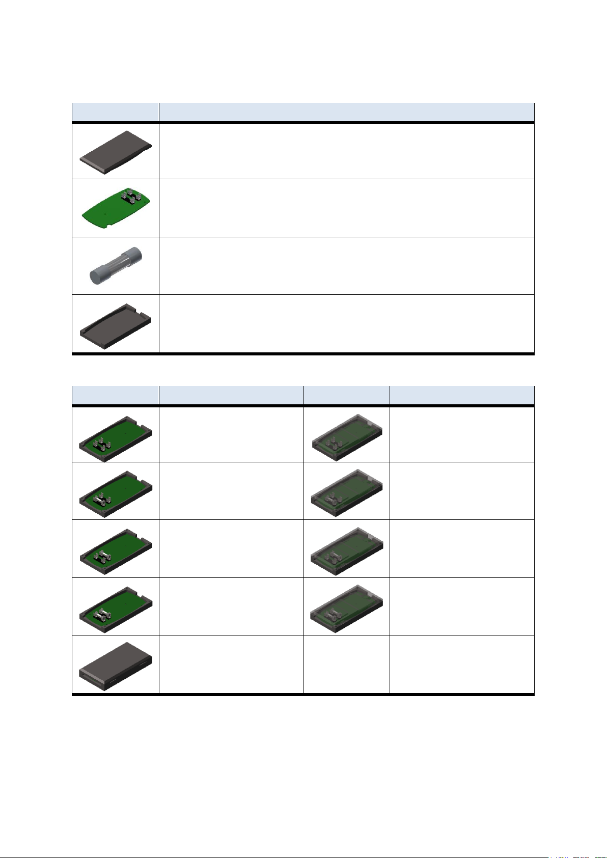
Workpieces
Description
CP back cover
no 111
CP board
no 120
CP fuse
no 130
CP front cover
no 210 - if there is a CNC milling machine integrated in the system, the front cover can also be produced
there , thus becoming a production part.
Workpieces
Description
Workpieces
Description
CP no fuse
no 211
CP part no fuse
no 1211
CP fuse on the left
No. 212
CP part fuse on the left
No. 1212
CP fuse on the right
no 213
CP part fuse on the right
no 1213
CP fuses both
no 214
CP part both fuses
no 1214
CP part customer
no 1210 freely selectable
External production parts
Production parts
14 © Festo Didactic CP Factory ° Robot feeding for mill
Page 15
Design and function
i
Warning
Before the transport, all supply roads must be cleared to be passable for the
industrial truck. If necessary, you have to install warning signs or barrier tapes.
When opening the transport boxes you have to be very careful because additional
components like computers may also be delivered with the box and have to be
protected against dropping out.
Caution
If the transport box is opened and the possibly additional components are taken
out, you can remove the station and bring it to its place of destination. Please
check the stability of all profile connectors with an Allen key size 4-6. It might
happen that the connectors are loosened during the transport due to inevitable
vibrations. Please pay special attention to any protruding components, sensors or
other small parts may easily be damaged during an improper transport. Do not
grab the station at or even under the pedestals – high risk of being crushed or
jammed!
3 Design and function
3.1 Transport
On delivery of the stations, special attention must be payed on transporting them only by a suitable
industrial truck.
The weight of a station may amount up to 500 kg.
3.2 Set up
3.2.1 General notes
You have to install the system in a frost-free room with a maximum relative humidity of 70 % and a
maximum ambient temperature of 25 ° Celsius. In countries with a higher humidity or higher temperatures,
you have to install air-conditioning systems for constant ambient conditions. You first have to check any
electrical disturbing sources like welding systems, big motors and contactors regarding their EMC and if
necessary to shield them in order to obtain the values permitted in the guidelines. A stable ground is
essential for a trouble-free operation in order to avoid subsidences. You have to see for an appropriate
distance between the system and the wall. Keep away any dust from the station resulting from construction
works (covering).
© Festo Didactic CP Factory ° Robot feeding for mill 15
Page 16

Design and function
3.3 Robot feeding for mill
3.3.1 General
The robot feeding for mill consists of a basic module bypass and a loading cell with robot as well as the CNC
machine. The conveyor belts have a width of 80 mm and a length of 1200mm. Carriers with workpieces can
be removed and transferred here for a longer processing. Thus, applications with a longer processing time
can be mounted on the bypass. The workpiece flow is not affected by the bypass line.
The conveyors are for transporting boards on carriers. The carriers are equipped with a read/write IDsystem. This ID-system represents an important item of the CP Factory System. Current data of the
workpiece to be transported is written on the carriers. Thus all information essential for the process is
transported together with the carrier and is therefore available at every station.
On bypass module an aluminum plate is mounted on a base frame. On this plate is a 6-axis robot and the
associated periphery. The robot is responsible for handling all processes within the module. For machining
the workpieces, a CNC machine is mounted on the base frame. The task of the station is to equip the CNC
milling machine with workpieces and to process the workpieces according to the requirements in the CNC
machine.
Different types of robots can be mounted, should there be differences in handling or the interfaces, this is
indicated separately in the operating instructions.
16 © Festo Didactic CP Factory ° Robot feeding for mill
Page 17
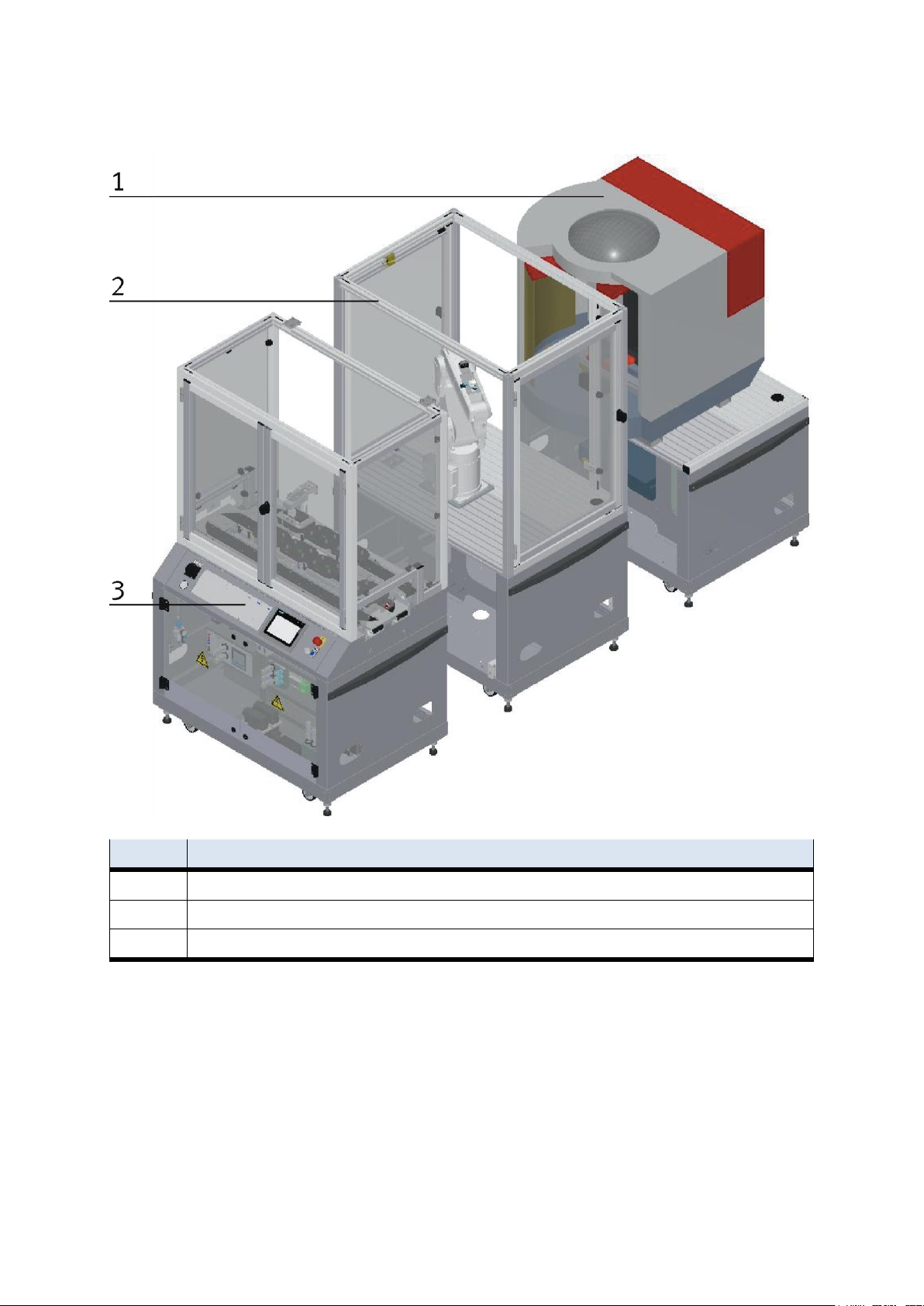
Design and function
Position
Description
1
CNC milling machine
2
Feeding robot for mill
3
Basic module bypass
© Festo Didactic CP Factory ° Robot feeding for mill 17
Page 18
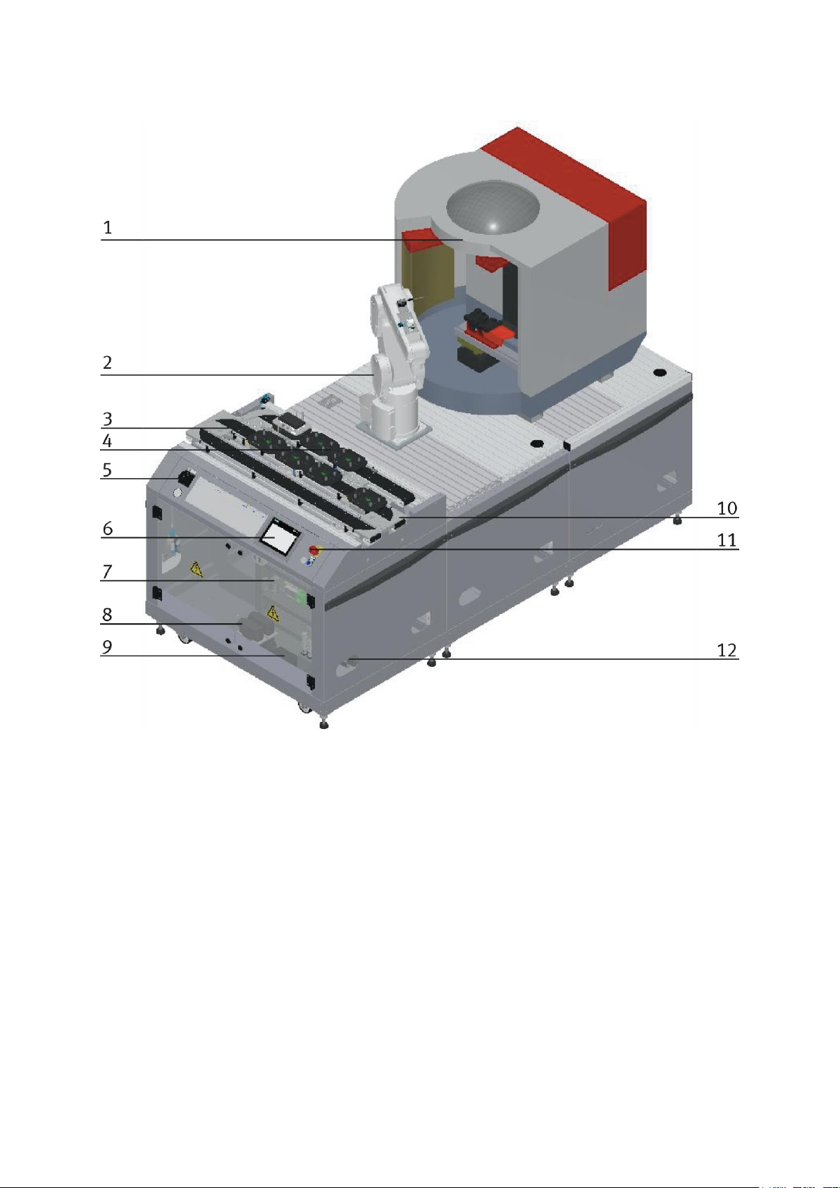
Design and function
CP Factory robot feeding for mill – front side
18 © Festo Didactic CP Factory ° Robot feeding for mill
Page 19

Design and function
Position
Description
1
CNC machine
2
Robot
3
Conveyor
4
Working position / workpiece carrier output slide
5
Main switch operation panel
6
Touchpanel
7
E-Board for basic module bypass
8
Multi contact plug
9
Pressure switch (option for energy monitoring) and RFID
10
removable corner pulley /other module available
11
Emergency stop
12
Passage for power supply
© Festo Didactic CP Factory ° Robot feeding for mill 19
Page 20
Design and function
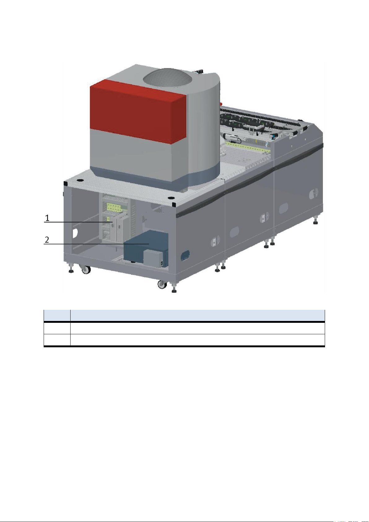
Position
Description
1
E-Board application
2
Drive Unit
CP Factory robot feeding for mill – back side
20 © Festo Didactic CP Factory ° Robot feeding for mill
Page 21
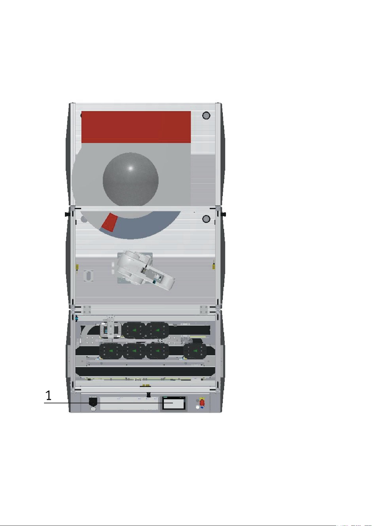
Design and function
3.4 Mechanical structure
The robot feeding for mill is designed for one-sided operation (1). The module is equipped with
mechanically adjustable feet. Should it be necessary to move the module to another place, it can be lowered
to its rollers and thus be transported easily.
© Festo Didactic CP Factory ° Robot feeding for mill 21
Page 22
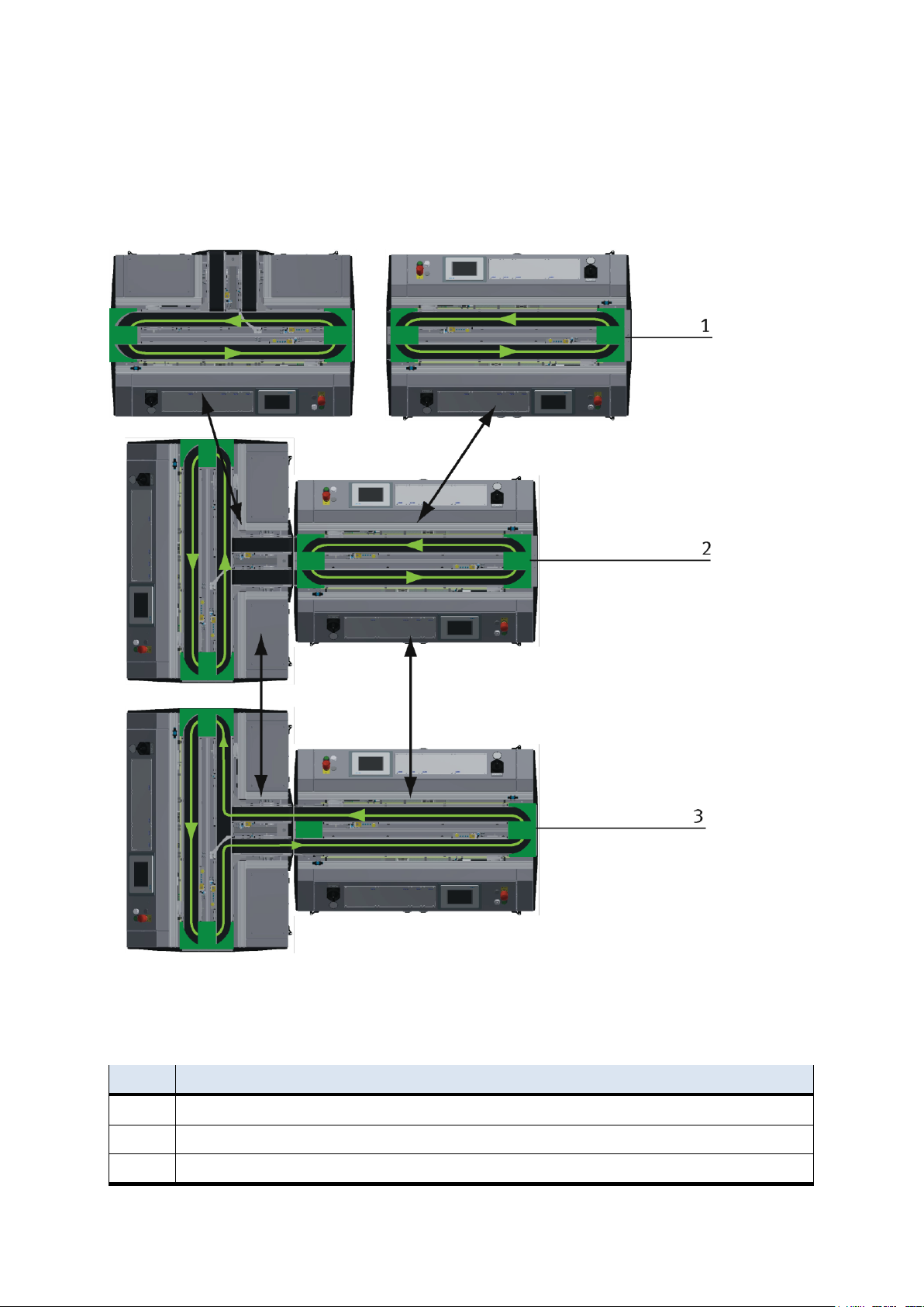
Design and function
Position
Description
1
Operation as independent Basic Module /not put together
2
Operation as independent Basic Module /Basic Module put together
3
Operation connected with another Basic Module
The modules can be operated in two ways - as a single station or in a chain with further modules. When
connected to a further module, it is necessary to replace the deflection at the end of the band by means of a
support plate. The switch is an exception, if this is operated as a single station, it is not possible to eject or
introduce workpieces via the switches.
Installation Options example
With the pluggable tape deflections there are different possibilities to control the transport flow. Depending
on this, different modules can be operated individually or in combination.
22 © Festo Didactic CP Factory ° Robot feeding for mill
Page 23
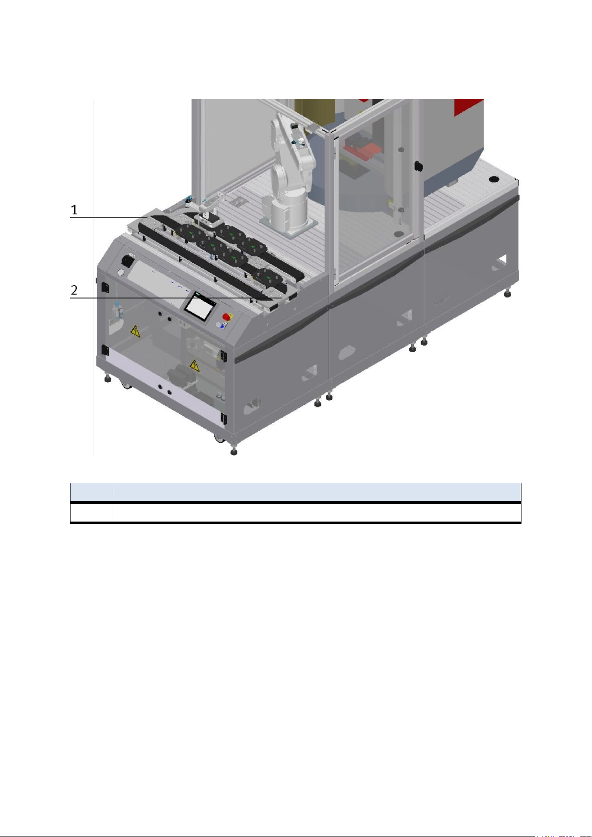
Design and function
Position
Description
1+2
corner pulley – the pallet carrier is reversed from one conveyor to the other on the Basic Module ByPass
Installation as independent module
© Festo Didactic CP Factory ° Robot feeding for mill 23
Page 24
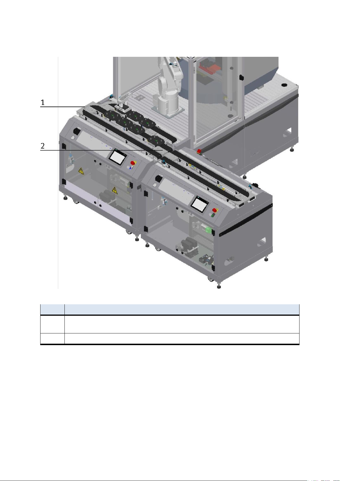
Design and function
Position
Description
1
Replacement guide board (support plate) if connected to another module – the pallet carrier is not reversed but directed
to the next module
2
corner pulley – the pallet carrier is reversed from one conveyor to the other conveyor on the Basic Module ByPass
Installation in combination with an Basic Module linear
The corner pulley and the support plate are only pinned and can be changed easily without tools.
24 © Festo Didactic CP Factory ° Robot feeding for mill
Page 25
Design and function
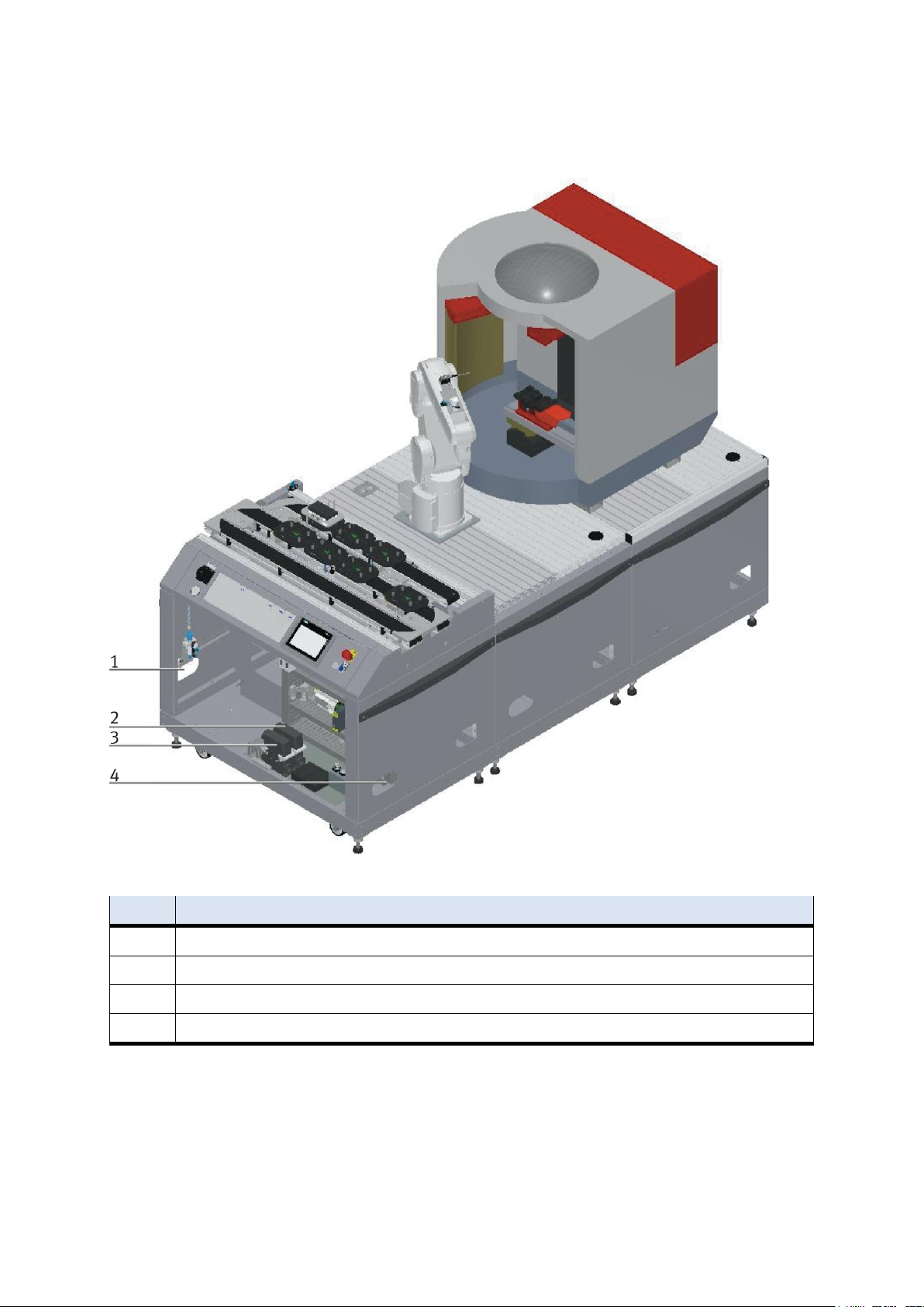
Position
Description
1
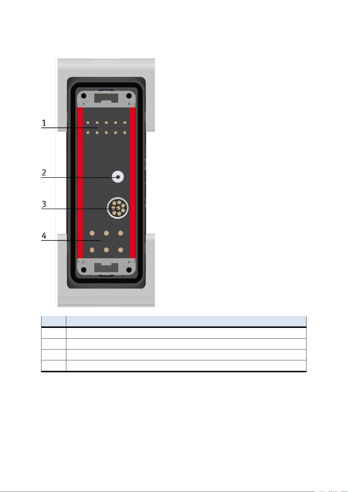
Inlet port for connection tube with voltage, communication and pneumatics
2
Connection plug K2-XZ1
3
Connection plug K2-XZ2
4
Outlet port for the connection tube of a further module
3.4.1 Supply of the Robot feeding for mill
CP Factory supply
© Festo Didactic CP Factory ° Robot feeding for mill 25
Page 26
Design and function
Position
Description
1
Emergency chain linking
2
Pressure
3
Network
4
400 V
26 © Festo Didactic CP Factory ° Robot feeding for mill
Page 27
Design and function
3.5 Electrical set up
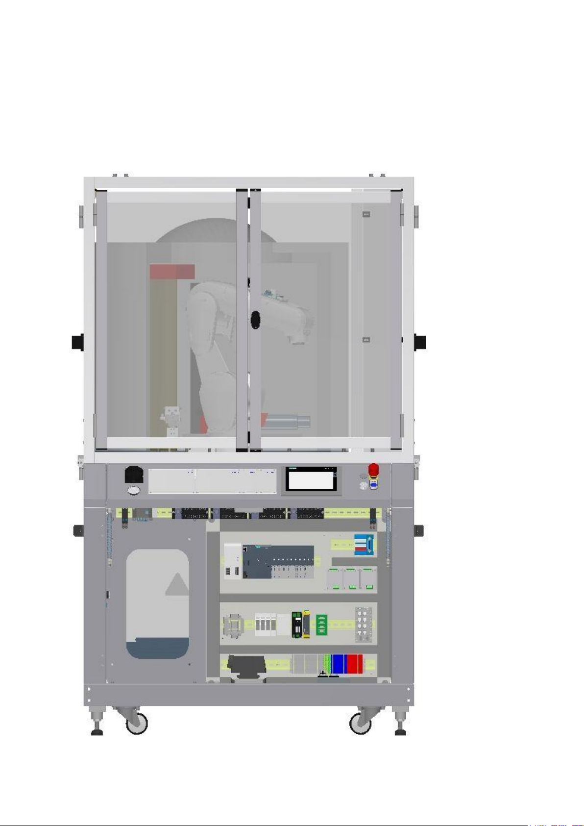
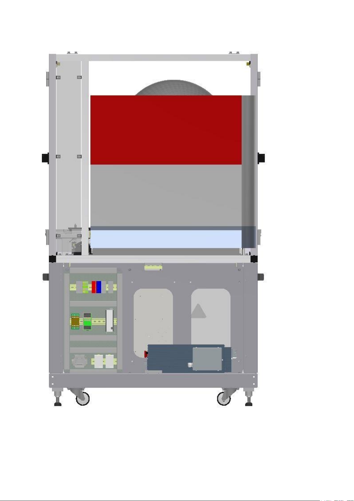
The robot feeding for mill has two electric boards. The main electric board is mounted on the front of the
base frame and is responsible for the conveyor belt with the bypass. The electric board for the feeding is
mounted on the back. The drive unit for the robot is also located on the back of the base frame.
E- Board robot feeding for mill front side
© Festo Didactic CP Factory ° Robot feeding for mill 27
Page 28
Design and function
E-Board robot feeding for mill back side
28 © Festo Didactic CP Factory ° Robot feeding for mill
Page 29
Design and function
Position
Description
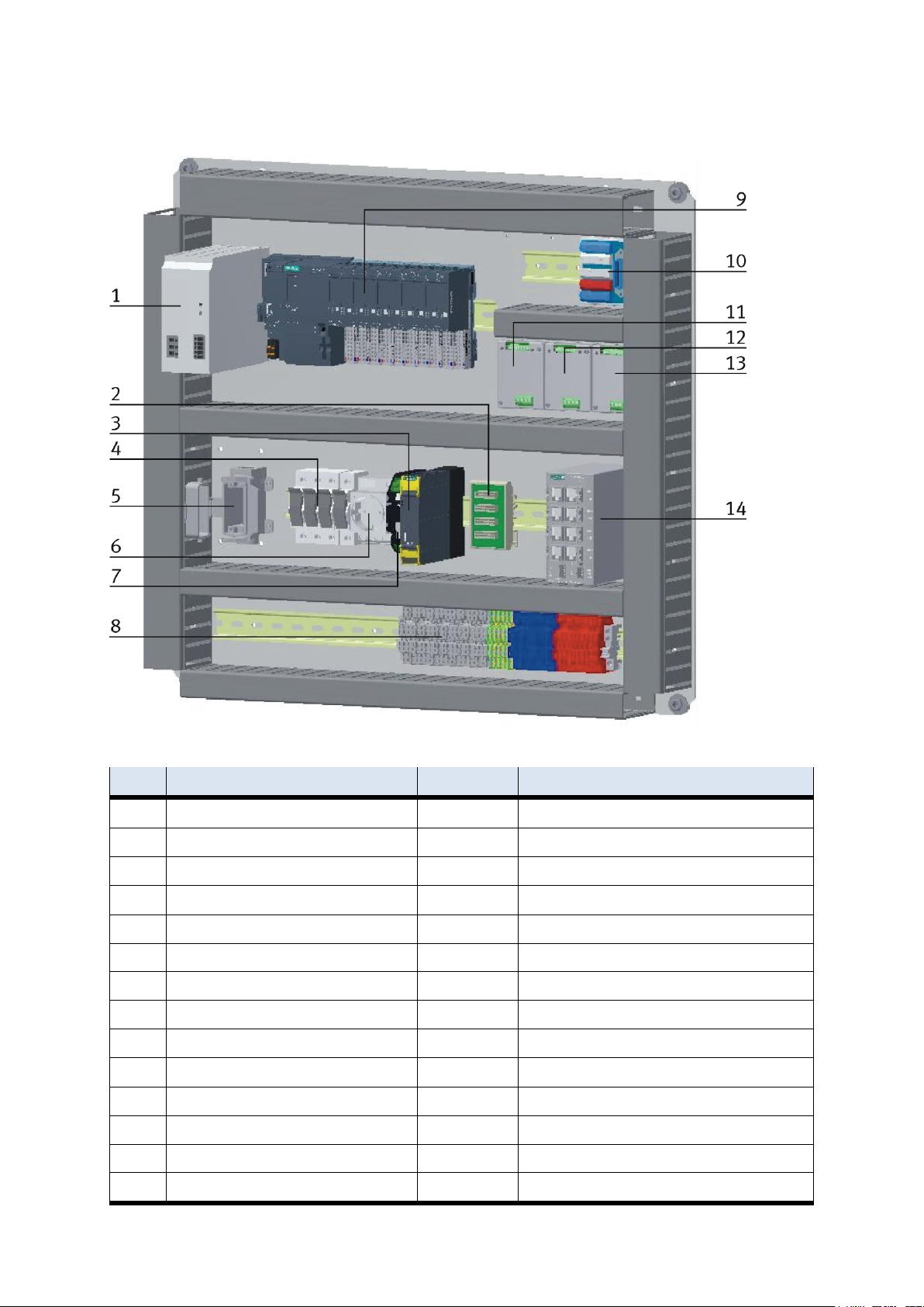
BMK
Description / Ordernumber
1
Power supply 24 V
K1-TB1
Festo CACN-3A-1-10 / 2247682
2
Emergency stop distributor
K1-F2-XZ2
3 Emergency stop unit
K1-F2-KF1
Siemens / 3SK1111-2AB30
4
Fuses
Han 10A-asg2-LB-M20
5
Harting plug
K1-FC1 + K1-FC2
6 protective contact socket 230 V
K1-XJ4
7 ELEC AUX CIRCUIT
K1-FC4
Murr Elektronik / 9000-41042-0100600
8
Clamps
K1 XD0-K1-XD13
9 PLC
K5-KF1
ET 200 SP CPU 1512SP F-1 P
10
I/O terminal
K1-XD15
11
Start-up current limiters
K1-QA1
Kaleja M-MZS-4-30 / 06.05.020
12
Start-up current limiters
K1-QA2
Kaleja M-MZS-4-30 / 06.05.020
13
Start-up current limiters
K1-QA3
Kaleja M-MZS-4-30 / 06.05.020
14
Ethernet Switch
K1-XF1
Siemens Scalance XB008 / 6GK5008-OBAOO-1AB2
3.5.1 Siemens PLC
E-Board front side conveyor with bypass
© Festo Didactic CP Factory ° Robot feeding for mill 29
Page 30
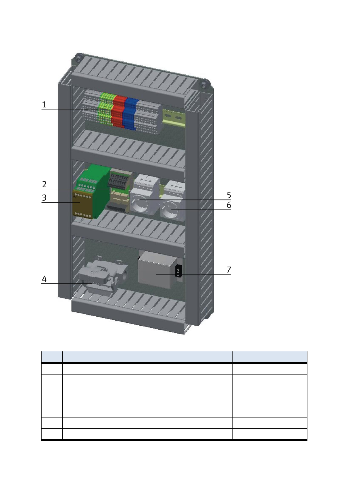
Design and function
Position
Description
BMK 1 Clamps for power distribution
XD1 / XD10
2
Pilz PSEN iX1
F2-KF3
3
Emergency stop unit PNOZ X8P
F2-KF2
4
Harting plug
XJ4 5 protective contact socket 230 V
XD3 6 protective contact socket 230 V
K6-XD6
7
MIT-SUP-EL20-ER-6
K6-KF2
E-Board back side robot feeding for mill
30 © Festo Didactic CP Factory ° Robot feeding for mill
Page 31
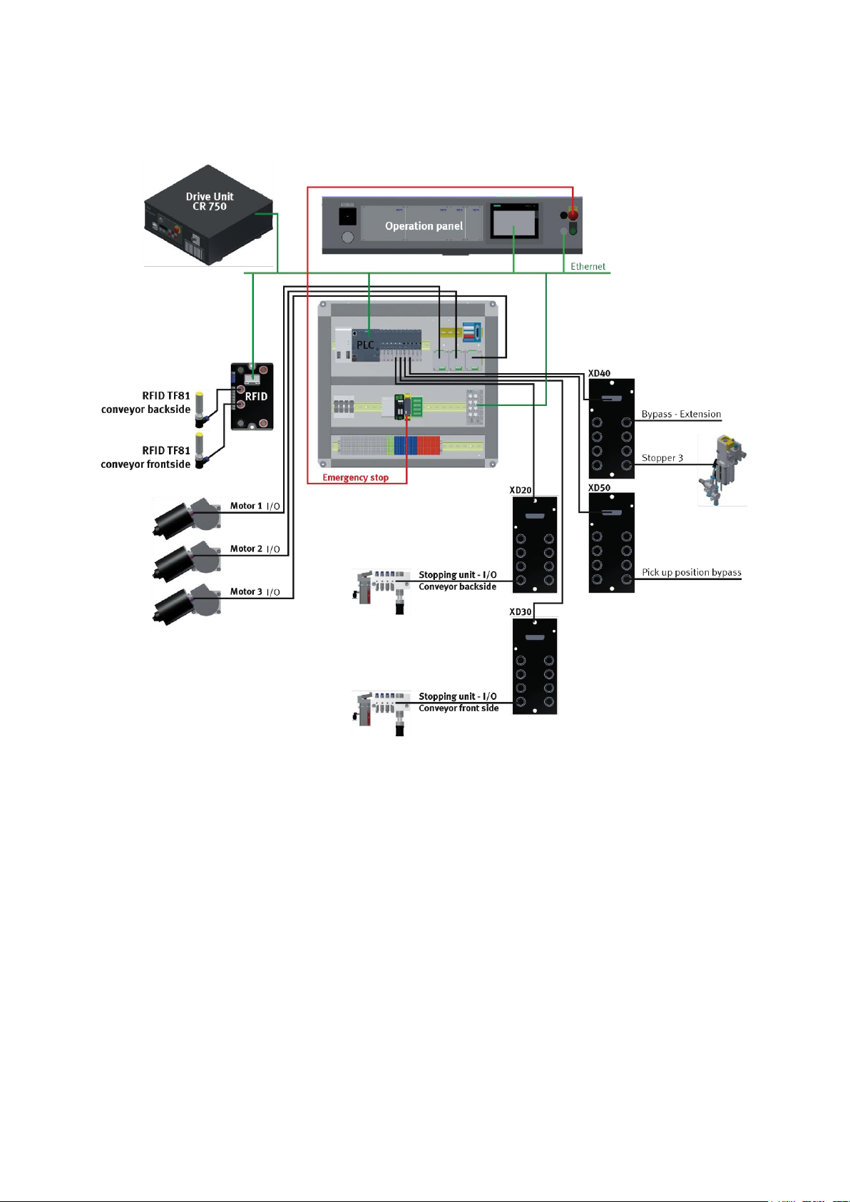
Design and function
3.5.2 Cabling chart
Overview cabling chart Mitsubishi / Siemens
© Festo Didactic CP Factory ° Robot feeding for mill 31
Page 32
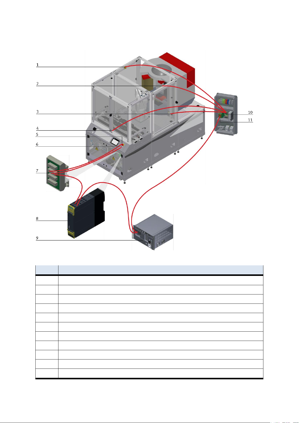
Design and function
Position
Name
1
Safety door / -H1-F2-FQ3
2
Safety door / -H1-F2-FQ2
3
Safety door / -H1-F2-FQ4
4
Safety door / -H1-F2-FQ1
5
Emergency stop switch F2-FQ1 / to emergency stop board X4:1: X4:3; X4:5; X4:7
6
Reset button SF2 / to PNOZ S33+S34; lamp clamp 24VNA/0V+
7
Emergency stop board for emergency stop linking / F2-XZ2
8
Emergency stop unit / F2-KF1
9
Drive Unit / K6-KF1
10
PSEN iX1 / F2-KF3
11
PNOZ X8P / F2-KF2
3.5.3 Emergency stop structure
The emergency stop components on the back side are firmly wired to the front. The type of control does not
matter.
32 © Festo Didactic CP Factory ° Robot feeding for mill
Page 33
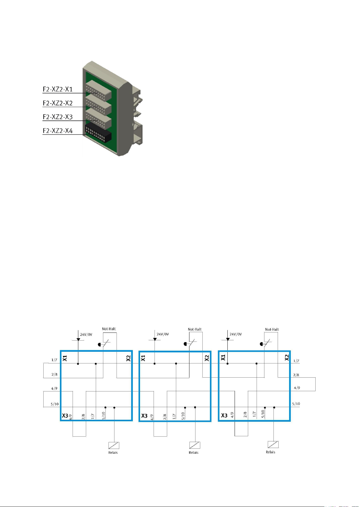
Design and function
Board Emergency-Stop interconnection
F2-XZ2-X1
Emergency-stop coupling input / If there is no previous station, you have to attach a bypass plug here or at
the system plug.
F2-XZ2-X2
Emergency-stop coupling output 1 / If there is no subsequent station, you have to attach a bypass plug here
or at the system plug.
F2-XZ2-X3
Emergency-stop coupling output 2 / for the connection of a further module or an external machine (e.g. for
the basic module shunt – another module can be placed here at the junction, or a CNC processing machine,
for example, can be placed at a bypass), otherwise you have to attach a bypass plug.
F2-XZ2-X4
Terminal clips for control panel, power supply, Emergency-stop relay.
Example for Emergency-stop linking with 3 modules
© Festo Didactic CP Factory ° Robot feeding for mill 33
Page 34
Design and function
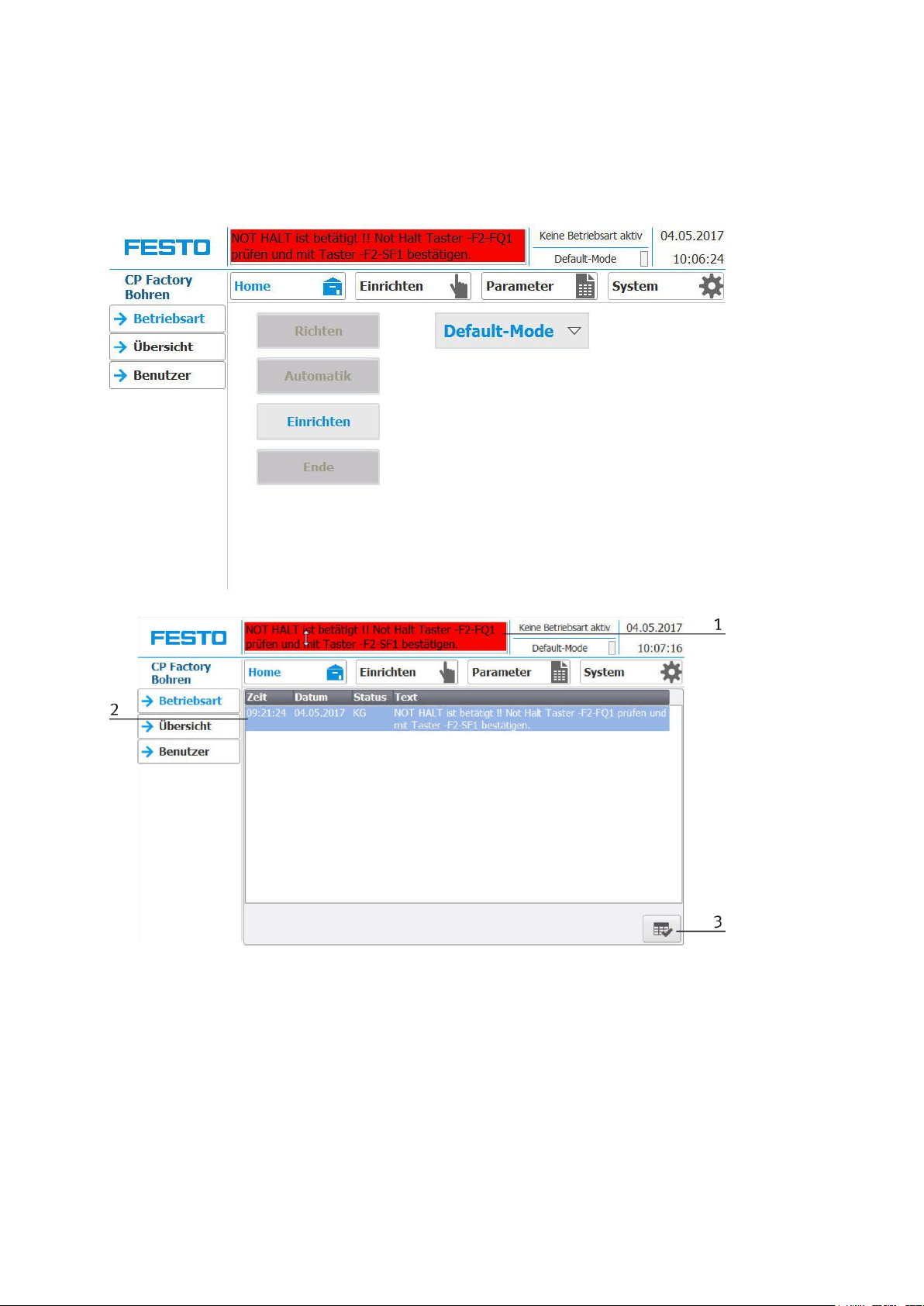
Enabling the Emergency-stop
If the Emergency-stop button has been pressed, a fault is indicated at the HMi. If you click on the message
line at the top, the fault will be indicated in the main window.
1. The emergency-stop situation is indicated in the message line. If you click on this line, the message will
appear in the main window.
2. Display of the emergency-stop situation.
3. When the emergency-stop situation is eliminated, you have to disconnect the emergency-stop
pushbutton. Then you have to press the blue illuminated pushbutton “Adjusting”. Now you can
acknowledge the message by pressing the button at the HMI. The module can now be restarted.
4. If the module has been connected with other modules, the emergency-stop is effective at all stations
and must therefore be acknowledged at every station by pressing the illuminated push-button
“Adjusting” and acknowledging the error at the HMi
34 © Festo Didactic CP Factory ° Robot feeding for mill
Page 35
Design and function
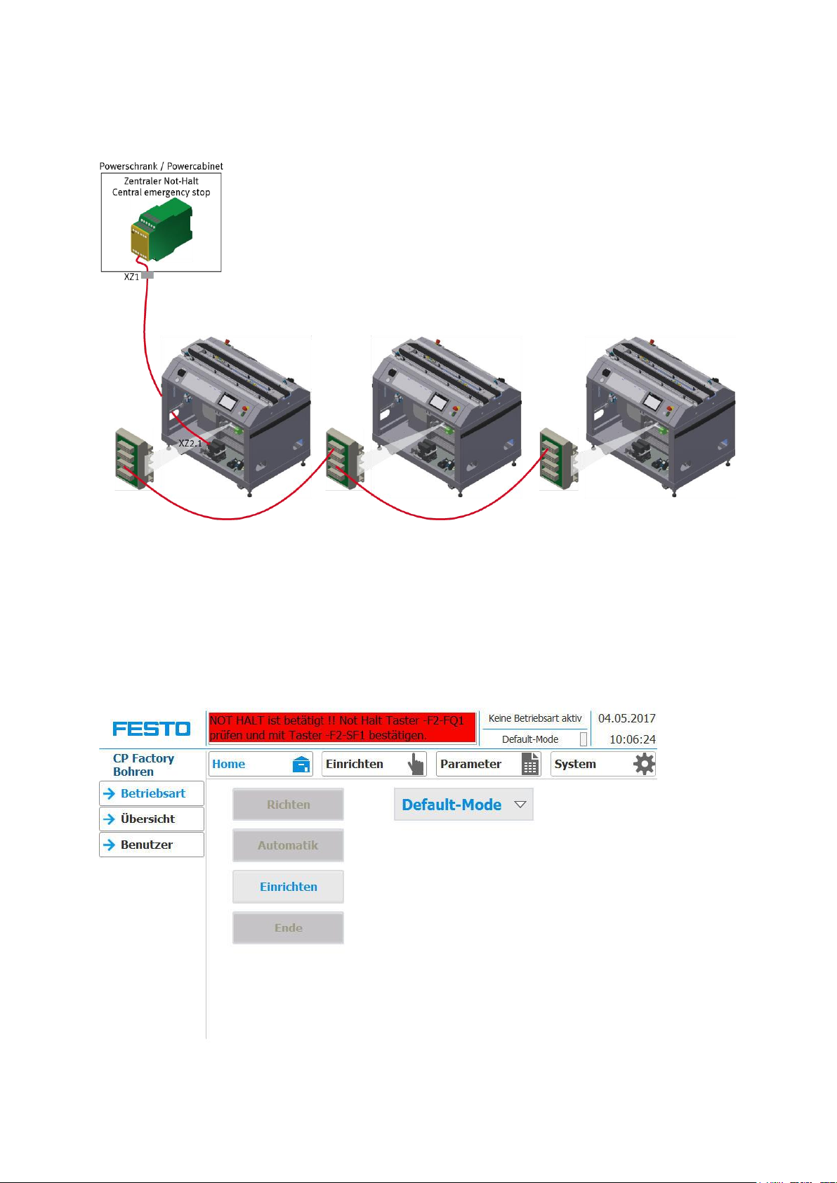
3.5.4 Emergency-stop with central control
Structure of the emergency-stop system
At the central emergency-stop (power cabinet), a central emergency-stop control unit PNOZ-X8P is
connected with one of the modules. The connection to one of the modules is effected by the energy supply.
Enabling the emergency-stop
If the emergency-stop has been pressed at any station, an error message is displayed at every HMI. First you
have to find out the station where the emergency-stop has been pressed. At this module, you can click on
the message line at the top at the HMI, where the error message will be displayed in the main window.
© Festo Didactic CP Factory ° Robot feeding for mill 35
Page 36
Design and function
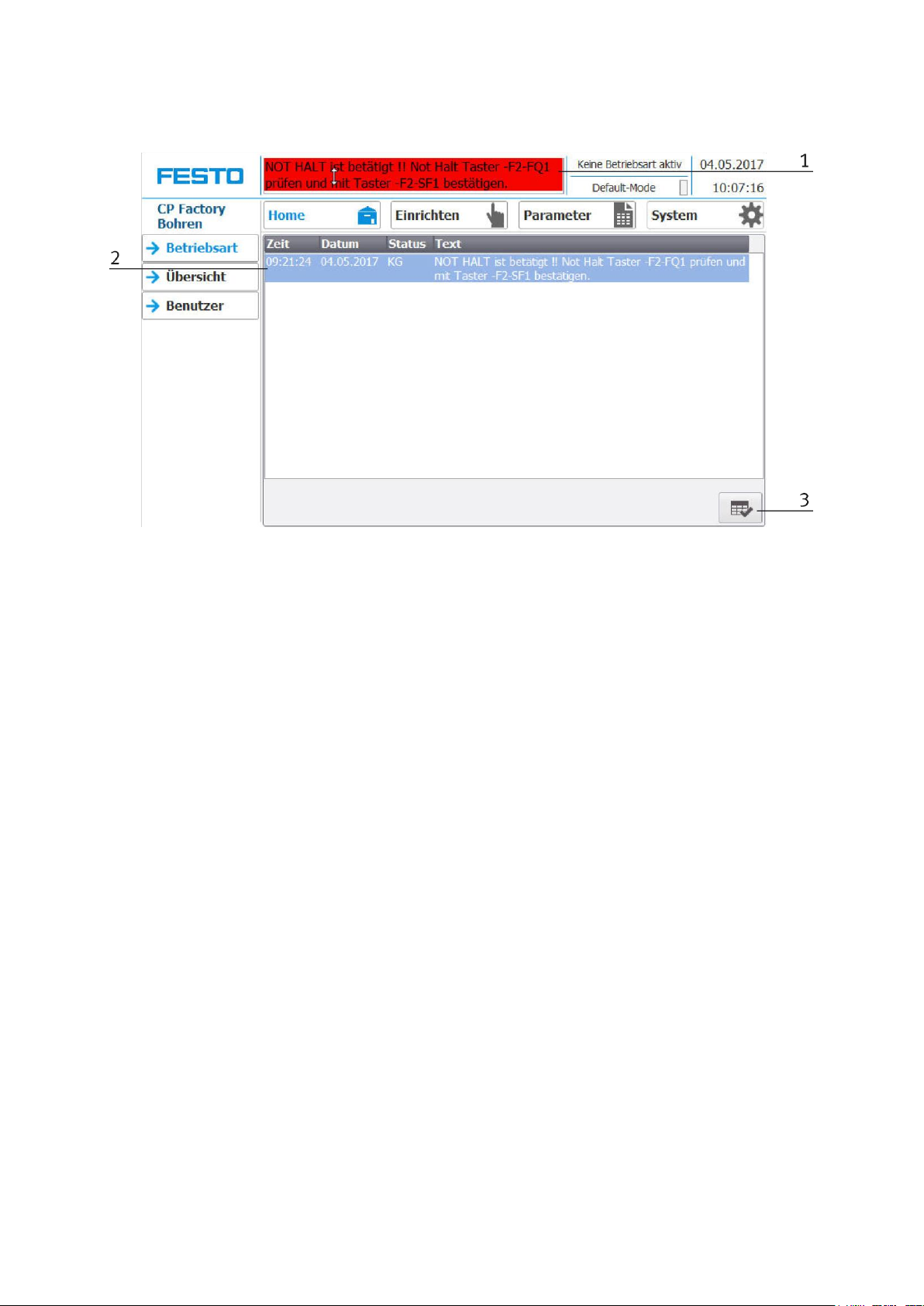
1. Emergency-stop situation is displayed in the message line. If you click on the line, the message will
appear in the main window.
2. Display of the emergency-stop situation.
3. If the emergency-stop situation has been eliminated, you have to disconnect the emergency-stop
pushbutton. After that, you have to press the blue illuminated pushbutton “adjusting”. Now you can
acknowledge the message by pressing the button at the HMI. The module can now be re-started. The
emergency-stop is effective at every station, therefore it has to be acknowledged at every station at the
HMI with the illuminated pushbutton “adjusting” and by acknowledging the error at the HMI.
3.6 Commissioning
The module has got several components which have to be connected on commissioning. The procedure will
be described in the following chapters.
3.6.1 Pneumatic commissioning
The mechanic assembly must be finished. First you have to connect the module to the pneumatic system of
the room. The service unit required has to be provided by the customer and should be within close
proximity. The quick coupling plug has got a nominal size of 5 mm. If the respective system is equipped with
7.9 mm nominal size it will be possible to exchange the coupling plug of the service unit by a bigger one
(adapter 1/8 to 1/4 required). Then the station can be supplied with 6 bar and the pneumatic
commissioning is finished.
3.6.2 Electrical commissioning
Now the module must be supplied with electric voltage (400 V). The voltage has to be provided by the
customer. Furthermore, an expert installation must be guaranteed.
36 © Festo Didactic CP Factory ° Robot feeding for mill
Page 37

Design and function
3.7 Commissioning
The robot feeding for mill has got several components which have to be attached when starting up. The
procedure will be described on the following pages.
3.7.1 Pneumatic commissioning
The mechanic mounting must be finished and completed. At first you have to connect the robot feeding for
mill to the pneumatic system of the room. The corresponding service unit has to be provided by the
customer and should be placed right next to it. The quick coupling plug has got a nominal size of 5 mm. If
the local system has got a nominal size of 7.9 mm, it is possible to exchange the quick coupling plug of the
service unit for a bigger one (adapter 1/8 to 1/4 necessary).
Now the station can be supplied by 6 Bar and the pneumatic commissioning is completed.
3.7.2 Electrical commissioning
Now the robot feeding for mill has to be supplied with electric voltage (400 V). The voltage has to be
provided by the customer. Professional installation must be guaranteed as well.
© Festo Didactic CP Factory ° Robot feeding for mill 37
Page 38
Design and function
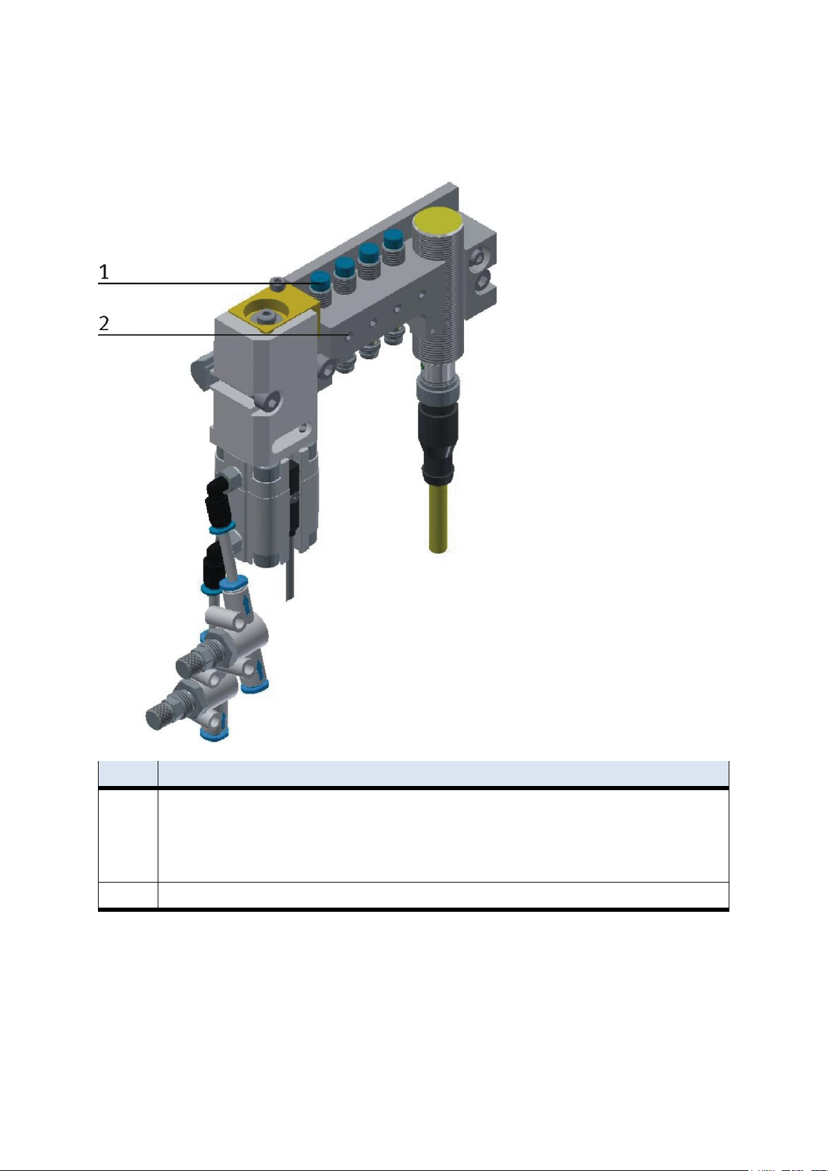
Position
Description
1
Sensor stopper identify sensor / 150395 (SIEN-M8NB-PS-S-L)
1 position (BG21/BG31/BG41)
2 position (BG22/BG32/BG42)
3 position (BG23/BG33/BG43)
4 position (BG24/BG34/BG44)
2
Screw to clamp the sensor
3.8 Adjusting the sensors
3.8.1 Proximity switch (stopper Identsensor)
The proximity switches are used for controlling the pallet.
38 © Festo Didactic CP Factory ° Robot feeding for mill
Page 39

Design and function
Requirements
– Stopper unit is attached to the conveyor.
– Electrical connection of the proximity switches is set up.
– Power supply is available.
Procedure
1. The stopper is in upper position, a pallet is stopped at the stopper.
2. Shift the switch as long as the switching status display (LED) appears.
3. Shift the proximity switch into the same direction by a few millimetres as long as the switching status
display disappears.
4. Shift the proximity switch halfway between the start-up and end position.
5. Tighten the locking screw of the proximity switch with an Allen key SW 1,3.
6. Check the position of the proximity switch by repeated removing the pallet.
Documents
Data sheets / operating instructions
Proximity Switch 150395 (SIEN-M8NB-PS-S-L)
© Festo Didactic CP Factory ° Robot feeding for mill 39
Page 40
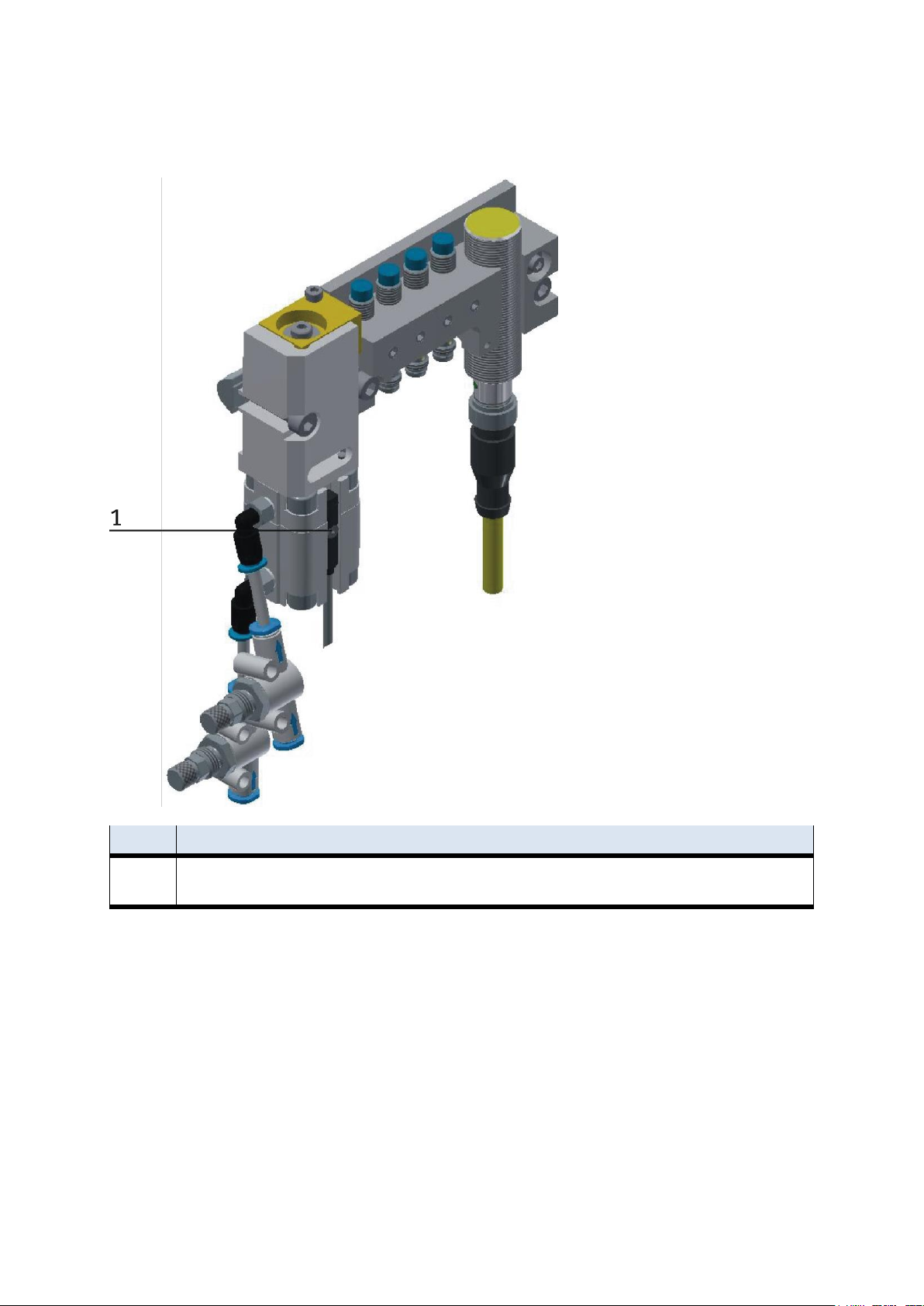
Design and function
Position
Description
1
Sensor stopper down/ 574334 (SMT-8M-A-PS-24V-E-0,3-M8D)
(BG20) / (BG30) / (BG30) / (BG40)
3.8.2 Proximity switch (stopper cylinder)
The proximity switches are used for controlling the end position of the cylinder for the stopper. The
proximity switches react to a permanent magnet on the piston of the cylinder.
40 © Festo Didactic CP Factory ° Robot feeding for mill
Page 41

Design and function
Requirements
– Cylinder stopper is attached to the conveyor.
– Pneumatic port of the cylinder is set up.
– Compressed air supply is switched on.
– Electrical connection of the proximity switches is set up.
– Power supply is available.
Procedure
1. The cylinder is in its end position to be queried.
2. Shift the proximity switch as long as the switching status display (LED) appears.
3. Shift the proximity switch into the same direction by a few millimetres as long as the switching status
display disappears.
4. Shift the proximity switch halfway between the start-up and end position.
5. Tighten the locking screw of the proximity switch with an Allen key SW 1,3.
6. Check the position of the proximity switch by repeated test runs of the cylinder.
Documents
Data sheets / operating instructions
Proximity Switch 574334 (SMT-8M-A-PS-24V-E-0,3-M8D)
© Festo Didactic CP Factory ° Robot feeding for mill 41
Page 42
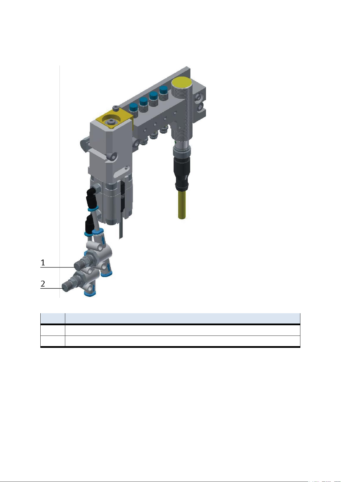
Design and function
Pos
Description
1
One-way flow control valves GRLA for stopper cylinder
2
One-way flow control valves GRLA for stopper cylinder
3.9 Adjusting the one-way flow control valves
One-way flow control valves
42 © Festo Didactic CP Factory ° Robot feeding for mill
Page 43

Design and function
One-way flow control valves are used for the regulation of the exhaust air volume of double-acting drive
units. In the opposite direction the air flows through the flow control valve having a full cross-sectional flow.
The piston is clamped between air cushions by free supply air and throttled exhaust air (improvement of the
operating behaviour even if the load changes).
Requirements
– Pneumatic port of the cylinders is set up.
– Compressed air supply is switched on.
Procedure
1. At first, turn off both one-way control valves completely. Then turn them on by about one rotation.
2. Start a test run.
3. Turn on the one-way flow control valves slowly as long as the required piston speed has been reached.
Documents
Data sheets
One-way flow control valve (193138)
3.10 Visual inspection
Visual inspection must always be done before starting up!
Before starting the station, please check:
the electrical connections
the correct fit and condition of the supply ports
the mechanic components regarding visible faults (cracks, loose connections etc.)
the function of the Emergency Stop
Please make sure that all damages discovered are removed before starting the station!
3.11 Starting up
For the robot feeding for mill, an „initial start-up“ has already been conducted.
In order to be able to work with the basic modules and the applications, you have to carry out the following
measures:
1. You have to provide the mains supply 400 V AC for the module.
2. The robot feeding for mill is supplied by about 6 bar compressed air. On initial start-up, please pay
attention to slowly increasing the pressure (herewith unpredictable events are prevented).
3. Now you can work with the module.
© Festo Didactic CP Factory ° Robot feeding for mill 43
Page 44

Operation
4 Operation
The chapter Operation describes the control units required for the operation, as well as start-up and closedown of the system.
4.1 General notes on operation
The stations demand strict adherence to certain rules of operation. Negligence in observing these rules may
cause errors in the stations’ processes. Also, damage to physical health cannot be excluded.
Strict observance of the following rules is demanded.
4.1.1 Handling regulations
Manual interference during the stations’ operation is prohibited.
In case of larger audience, a mechanical barrier of the station is required.
It is prohibited to pull off any cables while voltage supply is not deactivated.
Any kind of liquid is to be kept from the installation, at all times.
4.1.2 Operating regulations
The stations are to be operated only from trained personnel. Operation is to ensue according to operating
instructions.
Uncontrolled pressing of the various switches/push-buttons of the control units is to be omitted /
prevented.
No work-piece carriers should to be removed from the system.
44 © Festo Didactic CP Factory ° Robot feeding for mill
Page 45
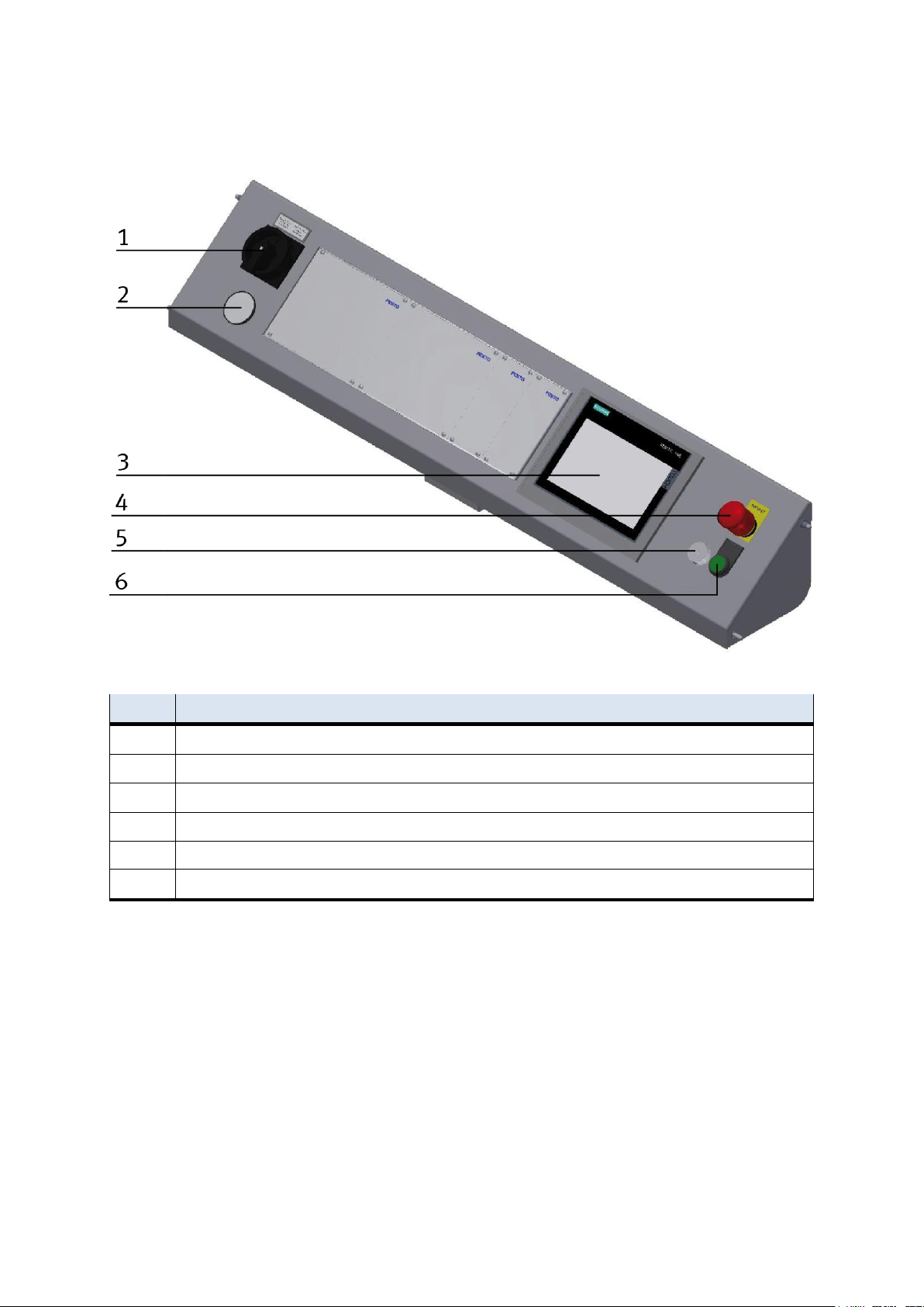
Operation
Position
Description
1
Main switch -QB1
2
Manometer
3
Touch Panel – PH1
4
Emergency- stop switch – F2-FQ1
5
Network socket- XPN3
6
Controller on pushbutton – F2-SF1
4.2 The control units of the robot feeding for mill
CP Factory control panel front side
© Festo Didactic CP Factory ° Robot feeding for mill 45
Page 46
Operation
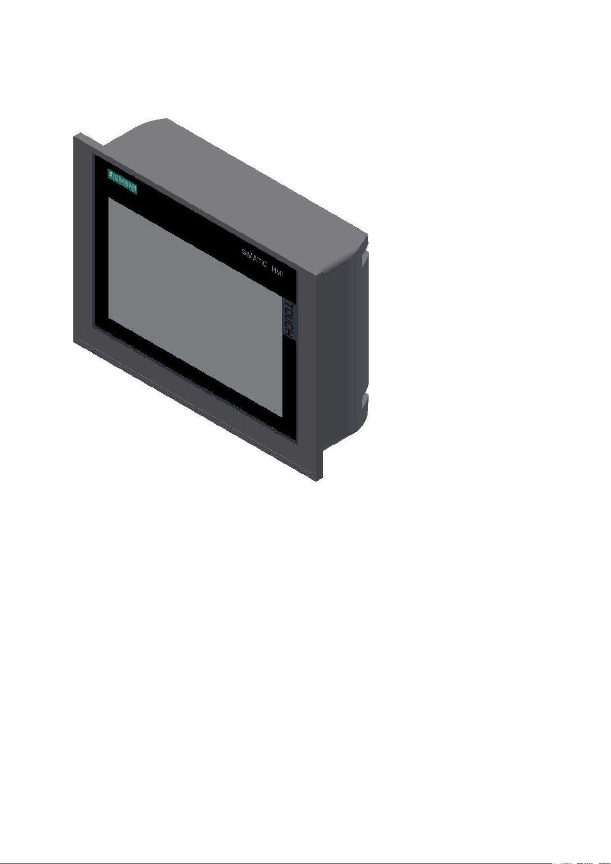
4.2.1 Touch Panel
Siemens TP 700 Comfort
Supply voltage
Type of supply voltage DC
Rated value (DC) 24 V
permissible range, lower limit (DC) 19.2 V
permissible range, upper limit (DC) 28.8 V
Input current
Current consumption (rated value) 0.5 A
Starting current inrush I²t 0.5 A²·s
Power
Power consumption, typ. 12 W
Processor
Processor type X86
Memory
Flash Yes
RAM Yes
Memory available for user data 12 Mbyte
46 © Festo Didactic CP Factory ° Robot feeding for mill
Page 47
Operation
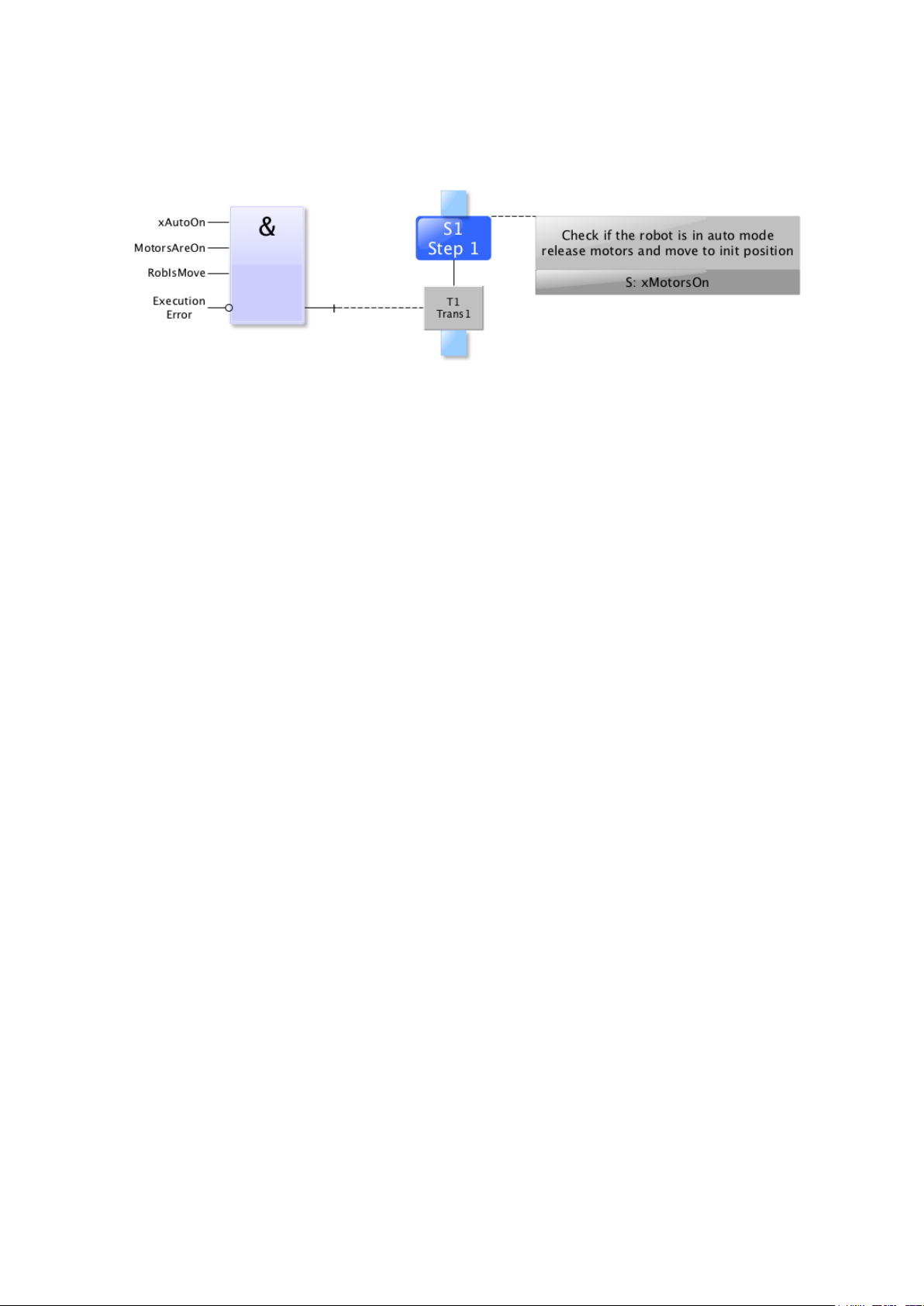
4.3 Sequence description of robot feeding for mill
Reset sequence
© Festo Didactic CP Factory ° Robot feeding for mill 47
Page 48
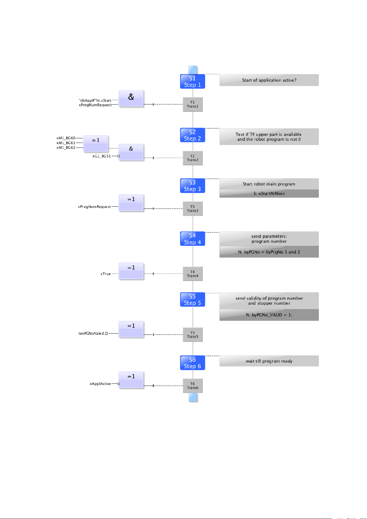
Operation
Automatic sequence
48 © Festo Didactic CP Factory ° Robot feeding for mill
Page 49
Operation
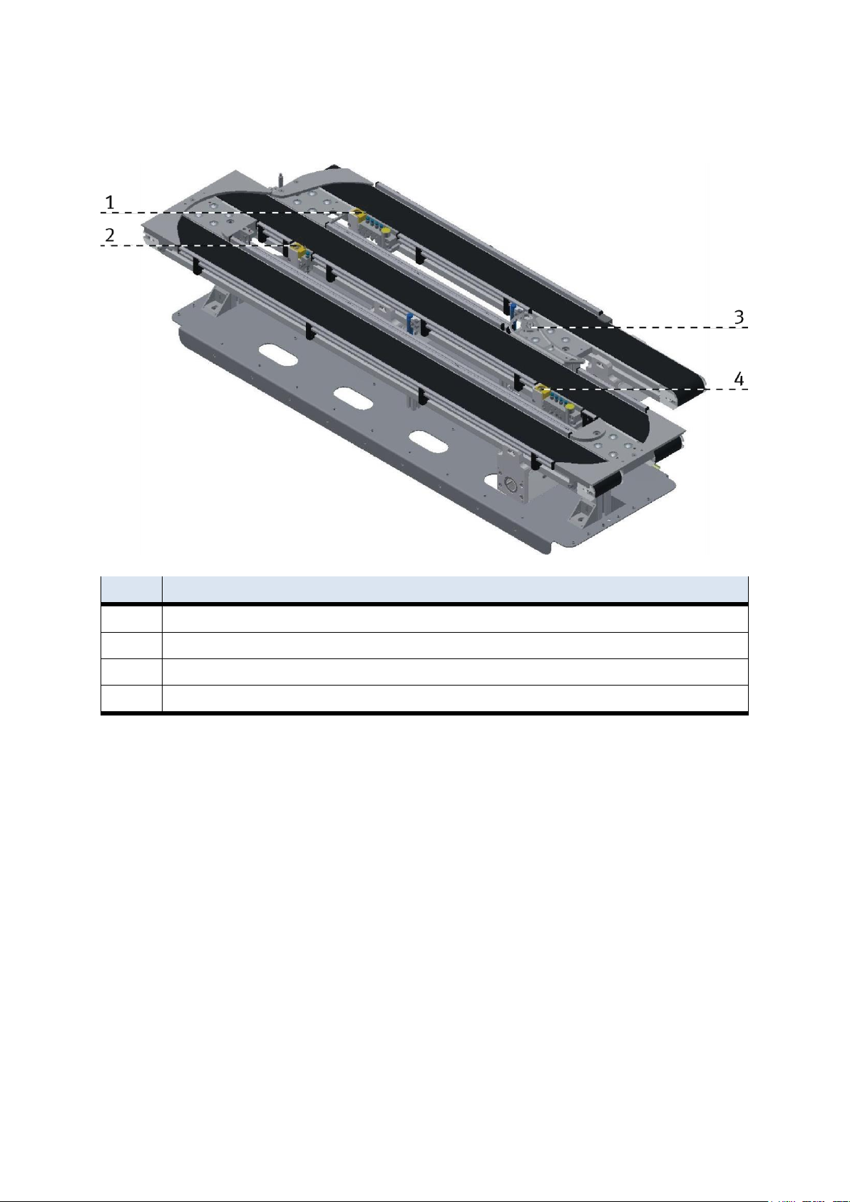
Position
Description
1
Stopper in bypass
2
Stopper without RFID
3
Branch
6
Stopper branch bypass
4.4 Sequence description of the Basic Module ByPass
© Festo Didactic CP Factory ° Robot feeding for mill 49
Page 50
Operation
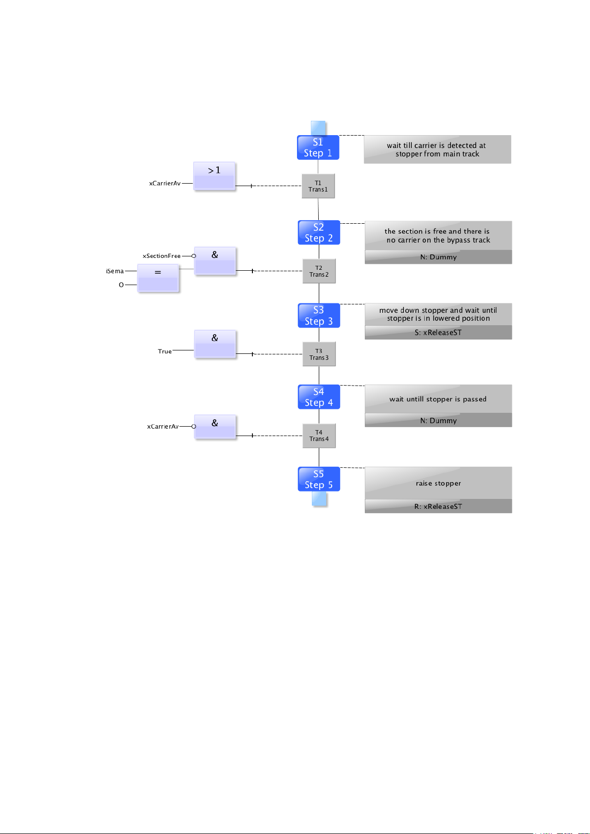
Sequence description bypass
stopper without RFID
50 © Festo Didactic CP Factory ° Robot feeding for mill
Page 51
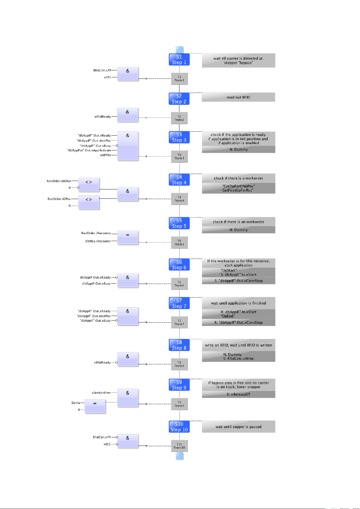
Operation
Automatic stopper in bypass area
© Festo Didactic CP Factory ° Robot feeding for mill 51
Page 52
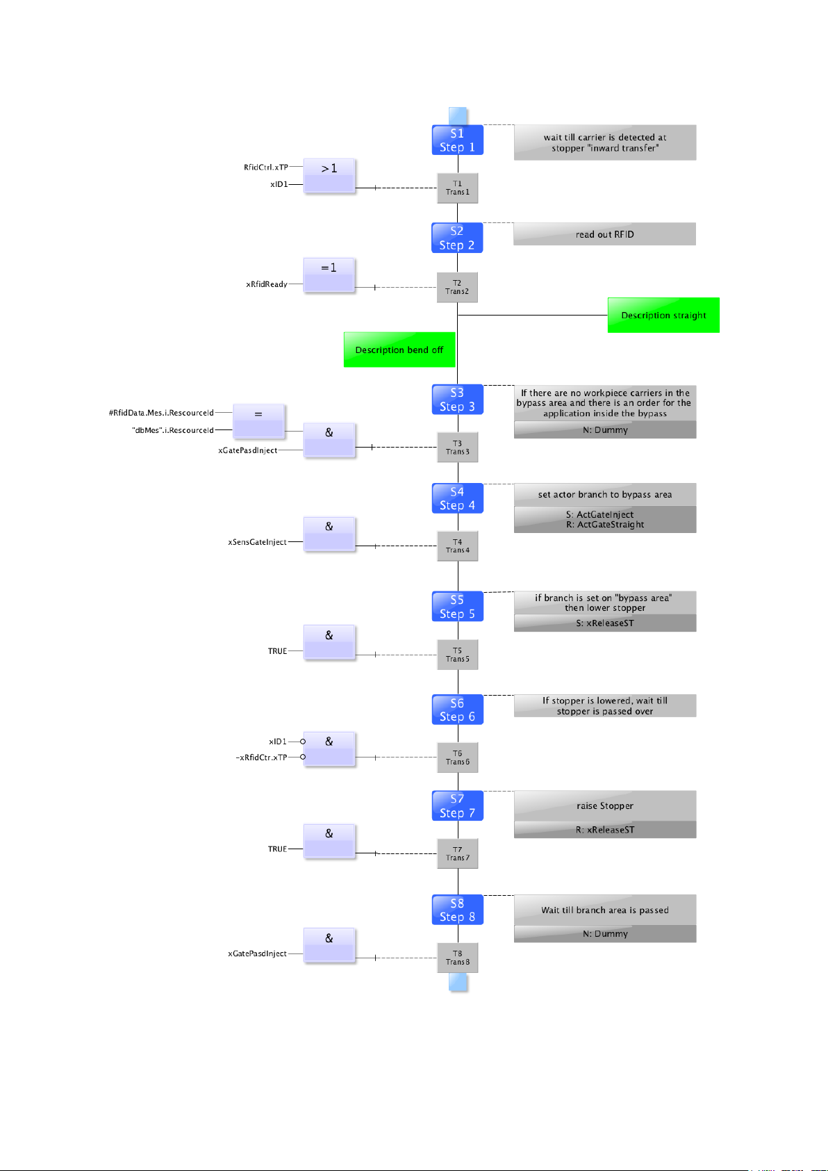
Operation
Bypass bend off
52 © Festo Didactic CP Factory ° Robot feeding for mill
Page 53
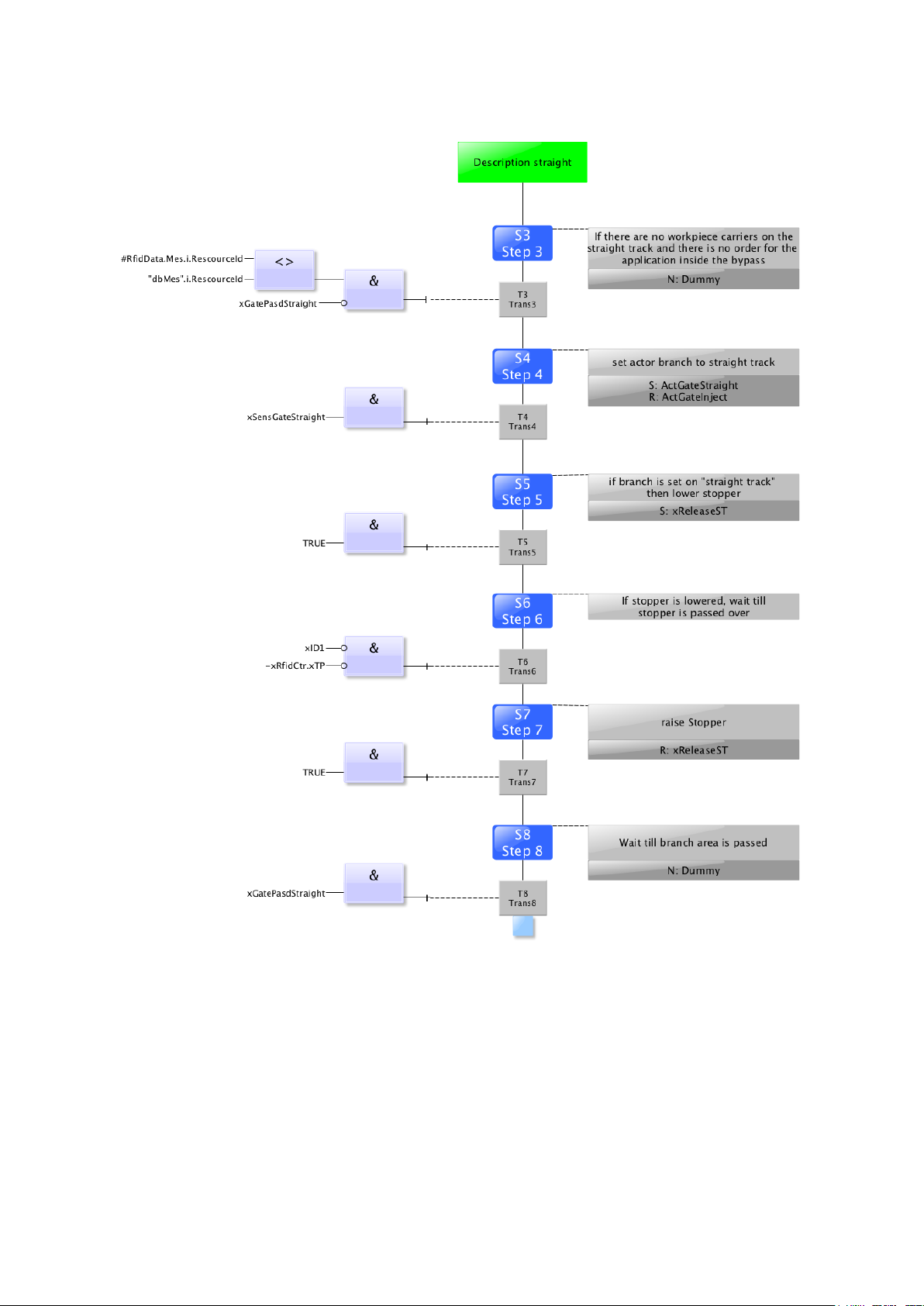
Operation
Bypass straight
© Festo Didactic CP Factory ° Robot feeding for mill 53
Page 54
Operation
4.4.1 CP Factory Loading Robot (Mill and Turn)
1. All EMERGENCY STOP signal transmitters (push buttons, door contact, light barriers, etc.) are not
activated or activated and unlocked.
2. Remove any existing workpieces from the clamping unit.
3. Switch on the main switch
4. Alignment button lights up blue, HMI is started and starts up
5. Switch on and start the PC of the CNC machine
6. If the automatic mode has already been started on the HMI, the DNC tool or the EMCO keyboard must
no longer be directed. The straightening process is carried out automatically in this case.
7. Start DNC Tool on Windows
The program is not displayed in the Windows taskbar, but can be reached via the "hidden icons" tray).
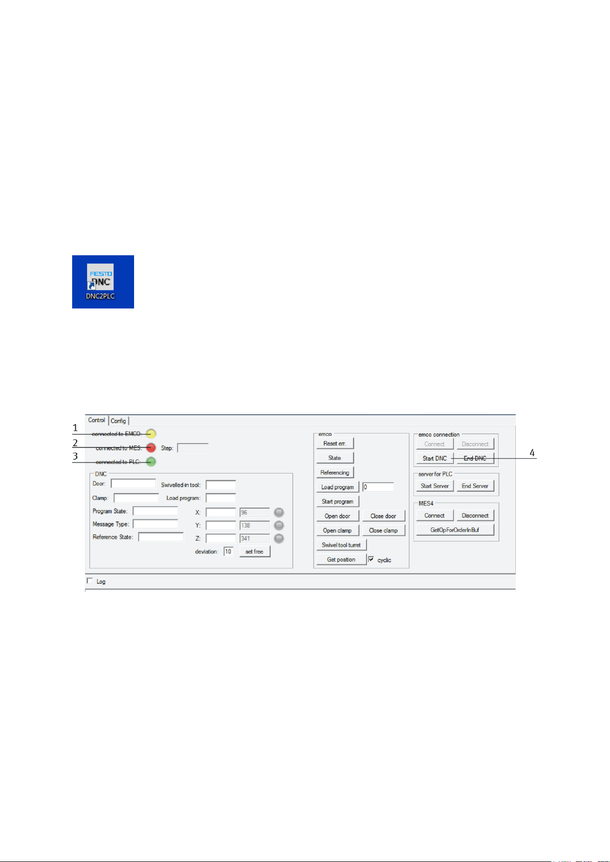
8. If the DNC Tool is started, the following connections must exist
Connected to EMCO - lights up green when connected to the CNC, otherwise yellow (1)
Connected to MES - lights up red because there is no direct connection from MES to the PC of the CNC
machine (2)
Connected to PLC -lights green if connection to PLC already exists, otherwise yellow (3)
9. The DNC connection must be displayed on the EMCO software. If this is not the case, the connection has
to be re-established. (4)
10. Select the function "HMI operate Mill" from the Emco display and confirm with OK
11. There are two ways to align the CNC machine, either with
the keyboard of the CNC machine *
or via the DNC Tool **.
12. Now align the robot straightening and the key switch on the TeachBox into the horizontal position
13. Select T1 mode
14. Set the key switch vertically
15. Delete error messages with Confirm
16. On the right-hand side of the Teachbox, select "Cell"
54 © Festo Didactic CP Factory ° Robot feeding for mill
Page 55
Operation
17. Select "Select" in the lower section
18. Lightly press the right or left safety switch on the back of the Teachbox until A1-A6 is green
19. Select Program No. 5
20. Press the arrow key to the right
21. Display jumps to program 8
22. Press the right arrow key again
23. Display jumps to program 9
24. Set the key switch horizontally
25. Select the "EXT" key
26. Set the key switch vertically
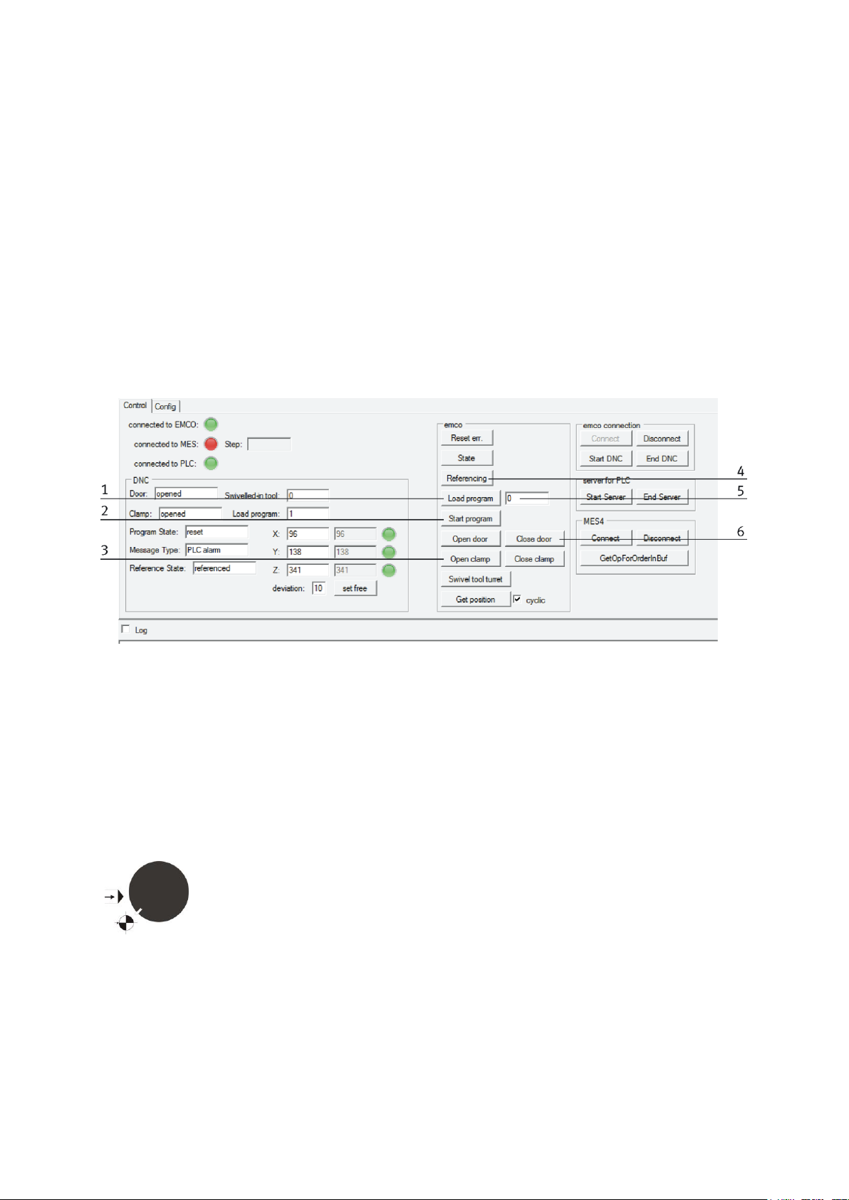
* Reset CNC machine with DNC Tool
Close the door (6)
Referencing (4)
Enter program 999 (5)
Load the program (1)
Start the program (2)
Open clamping device if this is not done automatically (3)
** Adjust the CNC machine with the Emco keyboard
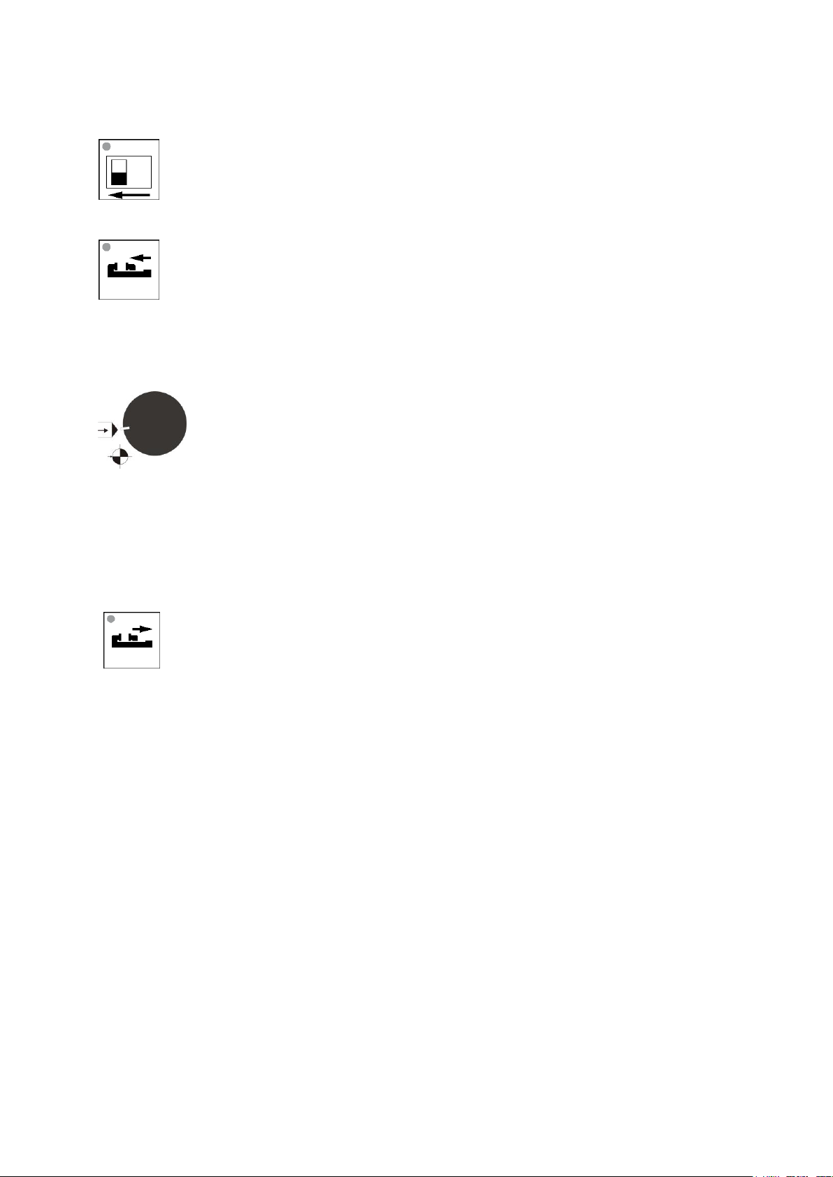
1. Turn the left rotary switch for the operating mode on the CNC keyboard to the "Reference mode"
position.
2. Turn the right rotary speed switch on the CNC keyboard to 20%
3. Close the door using this button.
© Festo Didactic CP Factory ° Robot feeding for mill 55
Page 56
Operation
4. Close the clamping device
5. Press the reference key, the CNC machine executes reference move and the key lights up
6. Now the speed can be increased to 100% with the rotary switch
7. When the reference run is completed, the reference button doesn’t lights up anymore
8. Rotate the left rotary switch for the operating mode on the CNC keyboard to the following position
9. Now press the right mouse button on one of the lower fields or press the "Program" button on the
Sinumerik control to open the program selection
10. Select a program e.g. Program 20
11. Press the Green Start button
12. Open the clamping device
13. Confirm any HMI error messages displayed
56 © Festo Didactic CP Factory ° Robot feeding for mill
Page 57

Operation
Should it be necessary to open the doors of the module, please make sure that
these doors are equipped with a safety switch. To prevent the robot from being
placed in an emergency stop situation, it is necessary to set the key switch to the
manual position on the drive unit. The robot is now in TeachMode and the doors
can be opened. Be very careful with the doors open, making sure that the robot
does not move. When the doors are closed again, the reset process must be
carried out again.
4.4.2 Switch on robot
1. Switch on the drive unit of the robot.
2. Switch on the TeachBox of the robot
3. It is important to keep the working area of the robot free!
4. The reset process is carried out via the touch panel on the basic module bypass.
5. Unlock the emergency stop button.
6. Press the reset button.
© Festo Didactic CP Factory ° Robot feeding for mill 57
Page 58

Operation
4.5 Operating modes
4.5.1 Automatic operation
MES mode
In the MES mode, all processes are centrally started, executed and monitored by the MES software. All
stations must be set to MES mode and automatic start.
Default Mode
The automatic sequence is not centrally controlled in the default mode, all information from the
transition tables (see chapter "Schematic process flow") is read and processed separately at each
station.
4.5.2 Setup mode
In setup mode, all sensors can be displayed and actuators can be controlled from the HMI. This is used for
troubleshooting or commissioning.
4.6 Operating the HMi Touchpanel
The operation on the basic modules is always the same. A basic module with the drilling module application
module serves as an example. Additional operating options are described separately in the respective
manuals. The operation is not dependent on the type of the control panel, Festo and Siemens Panel have the
same functions.
58 © Festo Didactic CP Factory ° Robot feeding for mill
Page 59
Operation
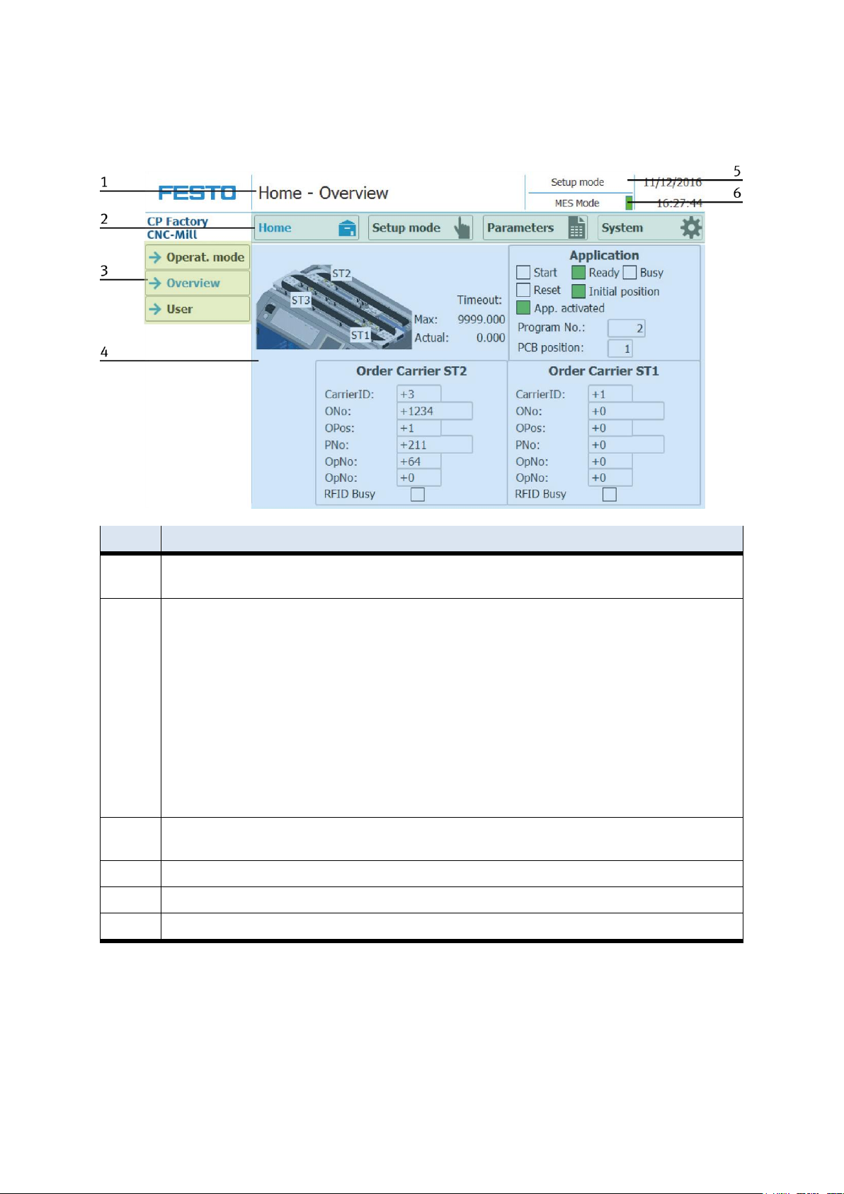
Position
Description
1
Description of menu (main or submenu) OR in case of an active Error or an error message, this field is also for
announcement
2
Main menu (always shown the same)
Operating mode Home:
Here the module can be controlled, the mode (default / MES) can be selected, the automatic or the set-up mode can also
be operated.
Operating mode Setup:
Here, the application can be operated manually in setup mode
Operating mode Parameter:
The parameters of the application are set here, a simulation can be started, the transitions can be defined, or the tape
can be set
System type:
Here the system parameters such as language, time, etc. are set
3
Submenu in the main menu
Changing content, depending on the main menu
4
Changing content, depending on the main or submenu
5
Announcement of operation mode automatic or set up
6
Announcement of default or MES Mode
4.6.1 Menu architecture from Panel
© Festo Didactic CP Factory ° Robot feeding for mill 59
Page 60

Operation
4.6.2 Menu navigation robot feeding for mill
General operation notice
White buttons with blue letters – function is active
White buttons with black letters – function is not active
Blue buttons – function is active – waiting for insert
Grey buttons with grey letters – function not available at the moment
Grey buttons with blue letters – function can be executed
Green advice – Sensor/function is active
Orange device – announce an actor
Blue “Connect” button - active if the robot is connected to the PLC
Blue “StartPrg” button - is blue until a program is running
“StartPrg” button - the robot makes the program which is define in the “byPrograNum” parameter
By default the byStopperPos is a constant and equal to 1, because there is no other position is defined
(this should be changed from the PLC program)
“xExitCycle” is exit from the actual program which is running
xRetryCycle” retries the actual state of the program
“ClearError” reset the connection and state of the PLC (not resetting the return value, that is handle by
the robot)
In setup mode there is no interactive message in case of a return value appears
In automatic in case of an error, an interactive message window appears with the Exit and Retry buttons
In case the door is opened a warning message appears in the top of the screen with yellow background:
“Safety doors opened”
If the robot controller is not in manual mode, the PLC recognize this as well as “Safety doors opened”
The doors can be opened while the robot is running. In this case there is no interactive error message,
only the yellow warning message. The robot stops, until the doors are opened. After closing them, the
robot keep continues its actual task
60 © Festo Didactic CP Factory ° Robot feeding for mill
Page 61
Operation
Position
Description
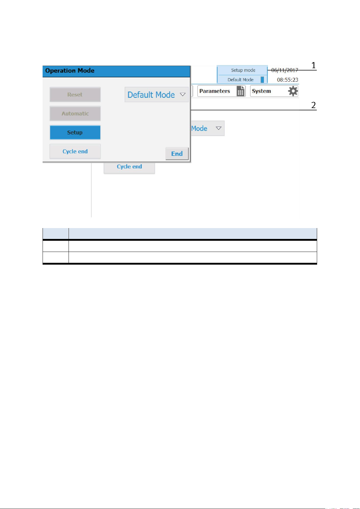
1
If you click on the blue marked field (no matter where you are in the menu), the following window will open (Pos 2)
2
Operating window – the operating window is always the same and allows a fast operating of the station
© Festo Didactic CP Factory ° Robot feeding for mill 61
Page 62
Operation
4.6.3 Display operation modus
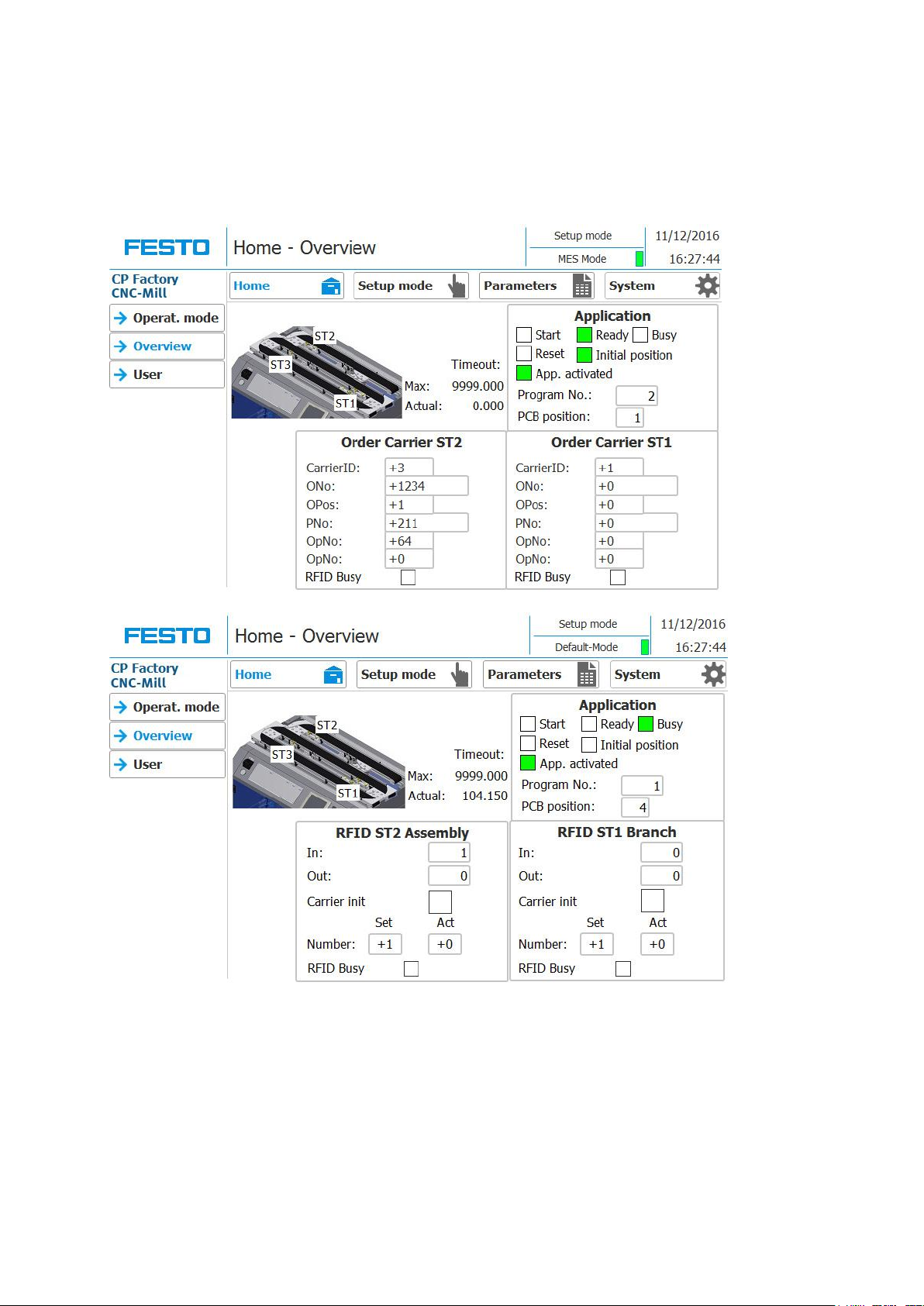
In the Home operating mode on the Overview page, different states can be displayed depending on the
mode (MES or Default).
In the upper right-hand area, the order data of the workpiece carrier are displayed in the MES mode, while
the RFID status code is displayed in the default mode.
The status of the application is displayed in the lower right area, which is independent of the selected mode.
62 © Festo Didactic CP Factory ° Robot feeding for mill
Page 63
Operation
Position
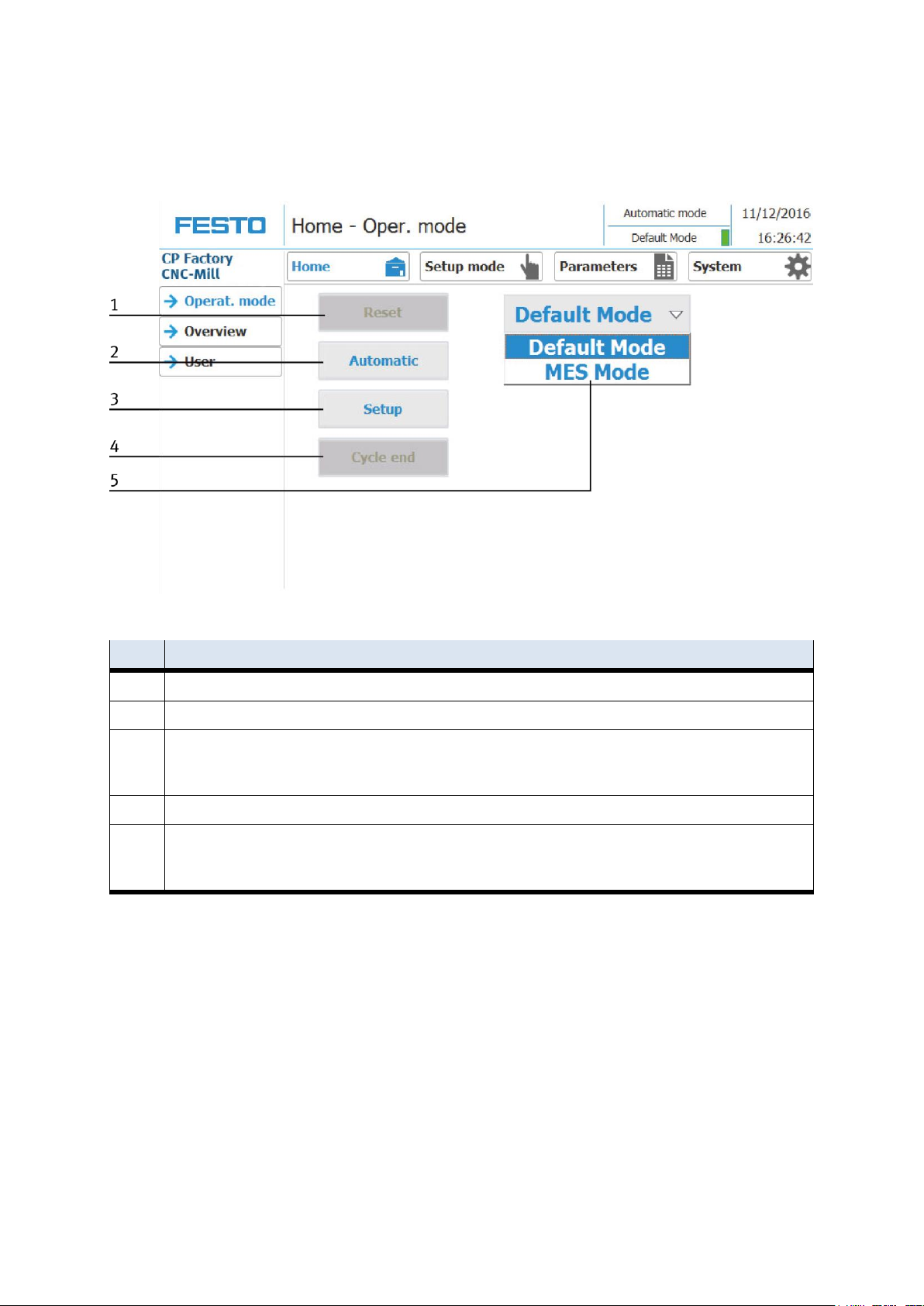
Description
1
Reset Button
2
Automatic Button: An automatic sequence is started depending on the mode (Default / MES)
3
Setup button: Here the application module can be controlled manually and sensors can be displayed. To put an application
module into operation or suitable for troubleshooting.
There is no difference in the mode - the setup mode is independent of the default or MES mode.
4
End Button: The currently active operating mode is stopped here.
5
Select the mode:
Default - Automatic sequence is executed with the stored transitions
MES software is fully controlled by MES software
4.6.4 Operation mode Home
Submenu operating mode
Operation mode is active, the setup can be started or an operation mode can be selected.
© Festo Didactic CP Factory ° Robot feeding for mill 63
Page 64
Operation
Position
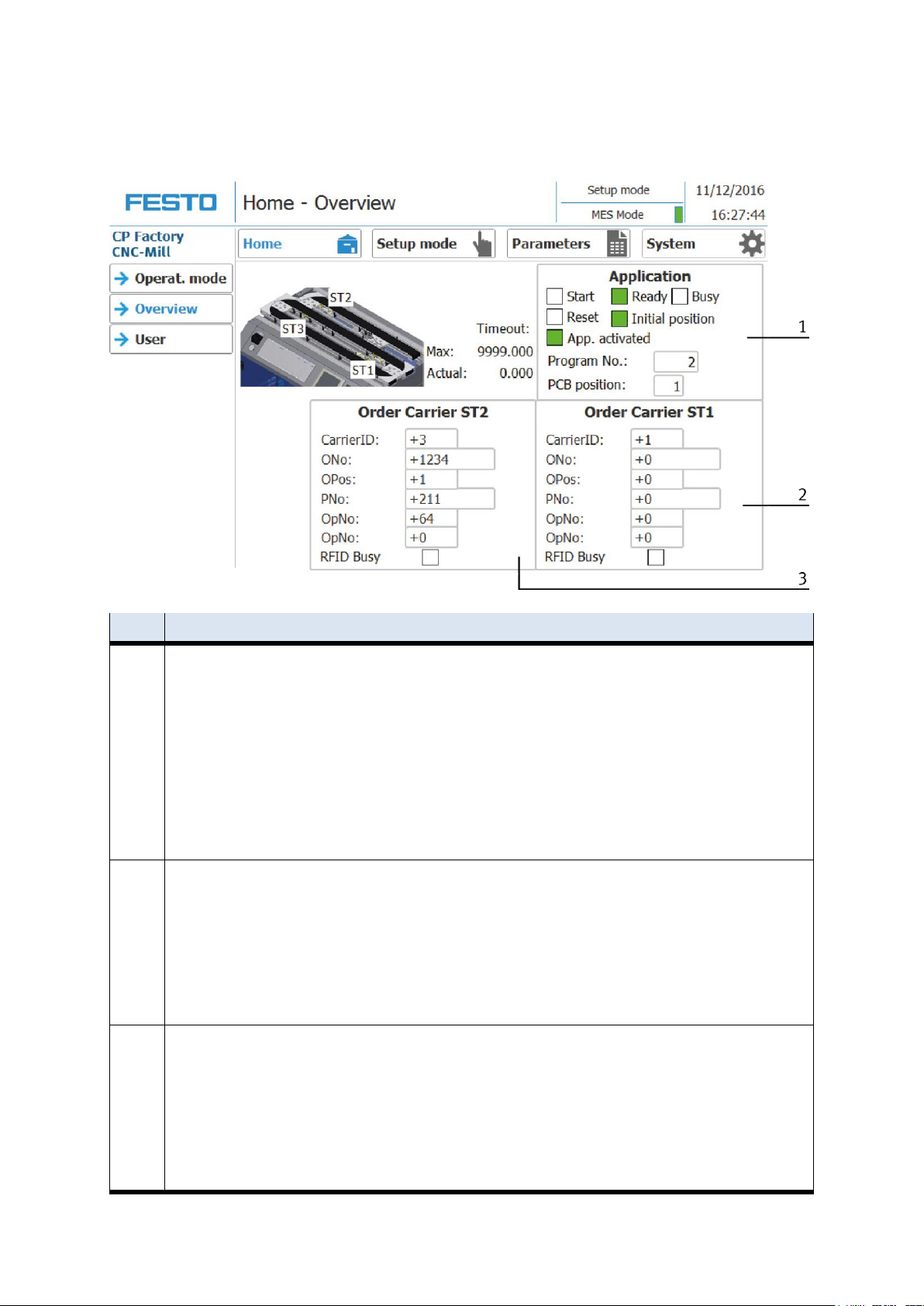
Description
1
Application area: here the status of the mounted application is displayed or the parameters are entered.
Start: Green when started
Ready: Green when ready
Busy: Green when the application processes an order
Reset: Green when the application is directed
Init Pos .: Green when the basic position is reached
Application active: green when the application is logged on to the basic module
Prog.: Display of active program number
Bott.fuse.: not used
Top fuse.: not used
PCB pos.: Position of circuit board inside the box
2
Area Order Carrier ST1 - the information provided by MES are standing on the workpiece carrier
Carrier ID: Carrier number
ONo: Order number
OPos: Order position
PNo: Part number
OpNo: Operation number
Resc: Resource
RFID Busy ( set hook to activate RFID)
3
Area Order Carrier ST2 - the information provided by MES are standing on the workpiece carrier
Carrier ID: Carrier number
ONo: Order number
OPos: Order position
PNo: Part number
OpNo: Operation number
Resc: Resource
RFID Busy ( set hook to activate RFID)
Submenu overview MES Mode
64 © Festo Didactic CP Factory ° Robot feeding for mill
Page 65
Operation
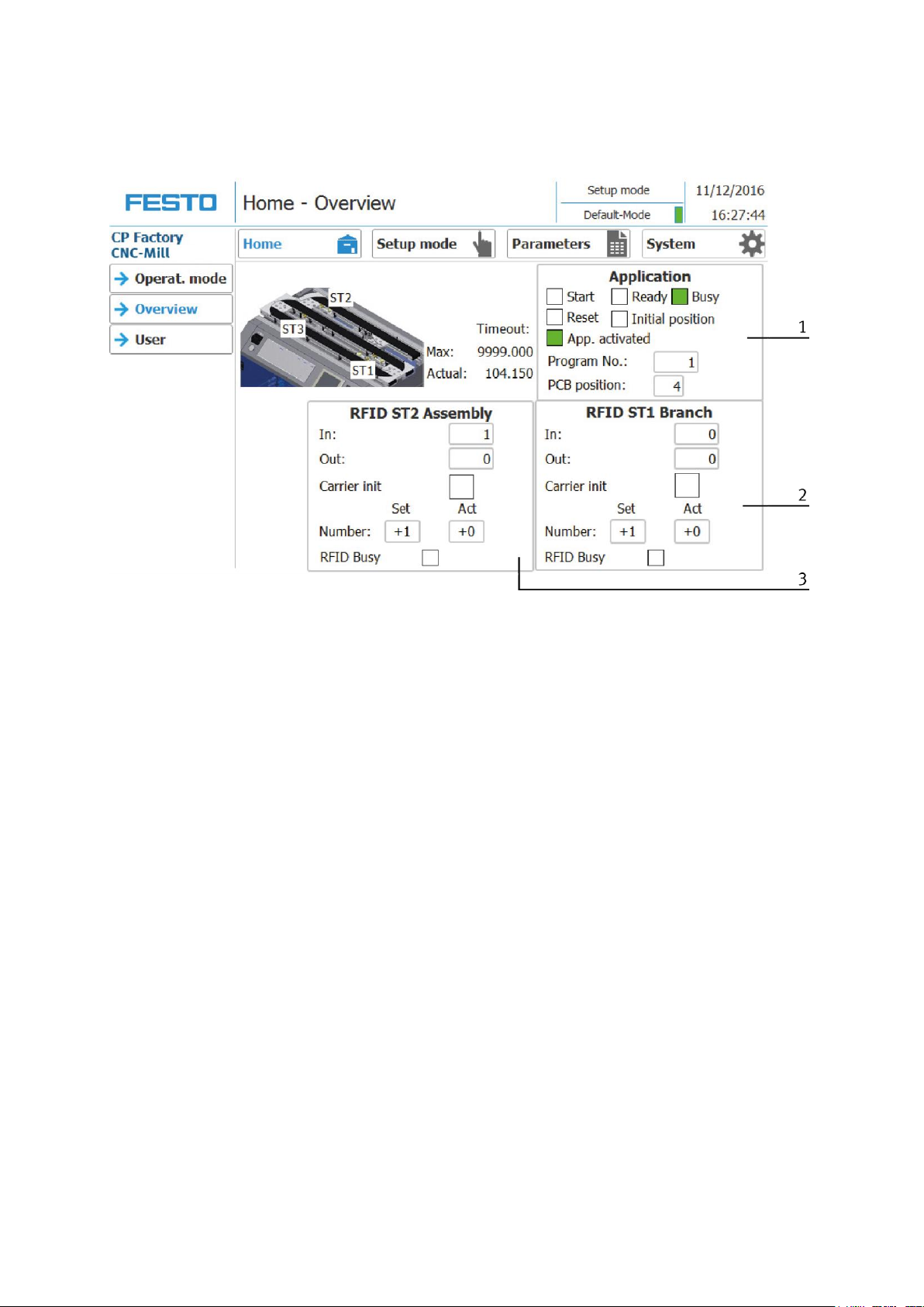
Submenu overview Default Mode
© Festo Didactic CP Factory ° Robot feeding for mill 65
Page 66

Operation
Position
Description
1
Application area: here the status of the mounted application is displayed or the parameters are entered.
Start: Green when started
Ready: Green when ready
Busy: Green when the application processes an order
Reset: Green when the application is directed
Init Pos .: Green when the basic position is reached
Application active: green when the application is logged on to the basic module
Prog.: Display of active program number
Bott.fuse.: not used
Top fuse.: not used
PCB pos.: Position of circuit board inside the box
2
Area RFID ST1 branch position: here are the informations read out by the RFID tag ST1
In: here is the transition of the incoming condition
Out: here is the transition which is written down to the RFID before leaving the application module
Carrier init: Here you can specify whether the carrier is to be initialized. If this option is activated, every incoming product
carrier is processed independently of the RFID condition code with the settings of the "Init" line of the transition table.
Number:
Set: determines in this context, how many goods carriers should be initialized according to the above procedure.
Act: Shows how many goods carriers have been initialized.
RFID active (tick to activate RFID)
3
Area RFID ST2 assembly position: here are the informations read out by the RFID tag ST2
In: here is the transition of the incoming condition
Out: here is the transition which is written down to the RFID before leaving the application module
Carrier init: Here you can specify whether the carrier is to be initialized. If this option is activated, every incoming product
carrier is processed independently of the RFID condition code with the settings of the "Init" line of the transition table.
Number:
Set: determines in this context, how many goods carriers should be initialized according to the above procedure.
Act: Shows how many goods carriers have been initialized.
RFID active (tick to activate RFID)
66 © Festo Didactic CP Factory ° Robot feeding for mill
Page 67
Operation
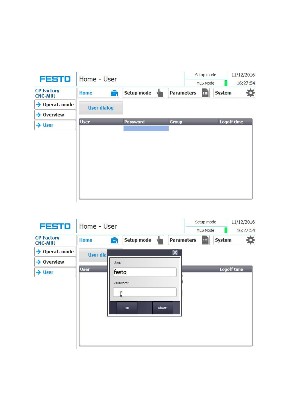
Submenu user
Here it is possible to create different operators. The function is independent of the selected mode (MES or
default)
Click on the button "User Dialog" to open the following window.
If you click on the User or Password fields, the input window opens and the user data can be entered.
© Festo Didactic CP Factory ° Robot feeding for mill 67
Page 68
Operation
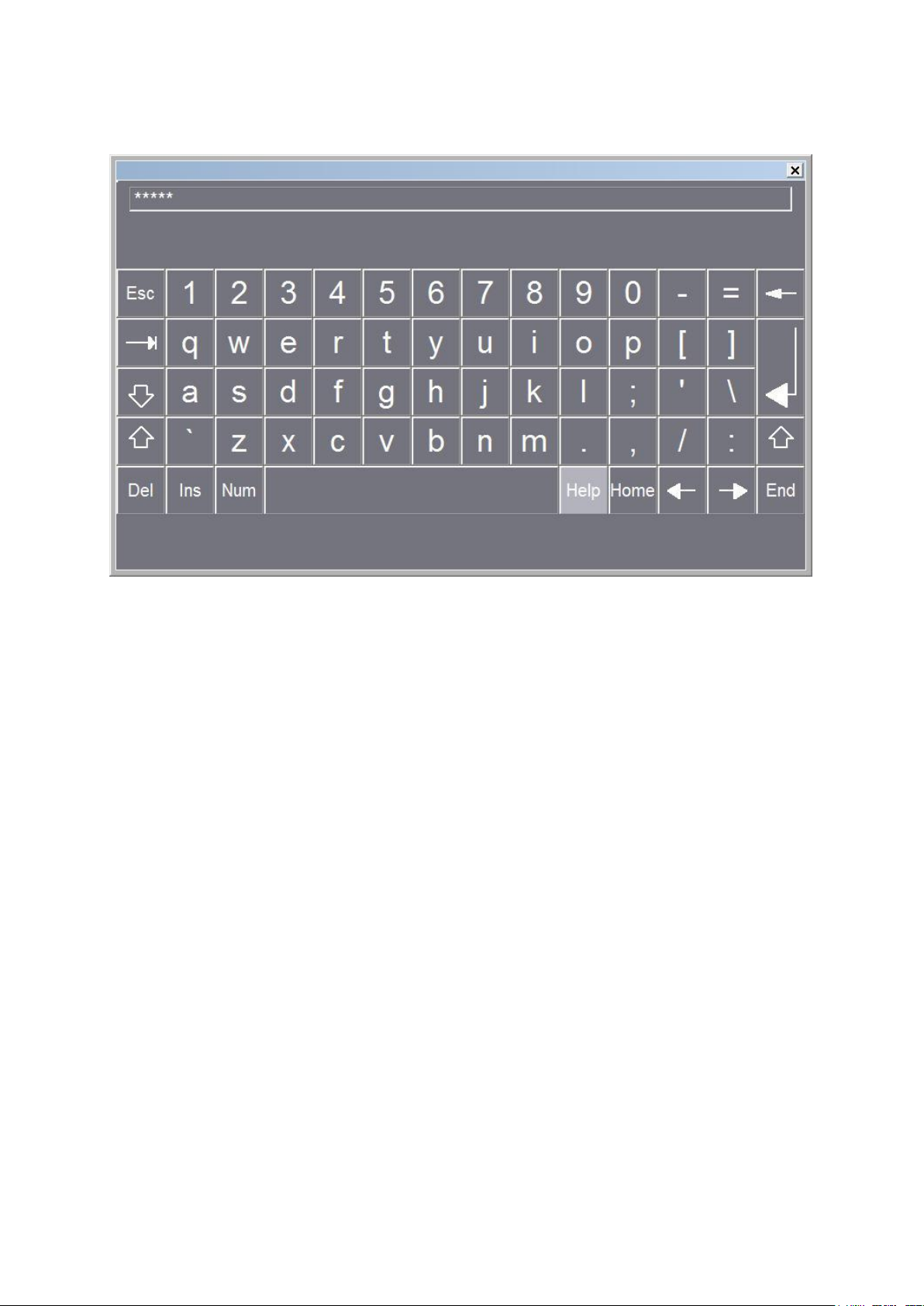
Here the user data can be entered, confirm with the return key.
68 © Festo Didactic CP Factory ° Robot feeding for mill
Page 69
Operation
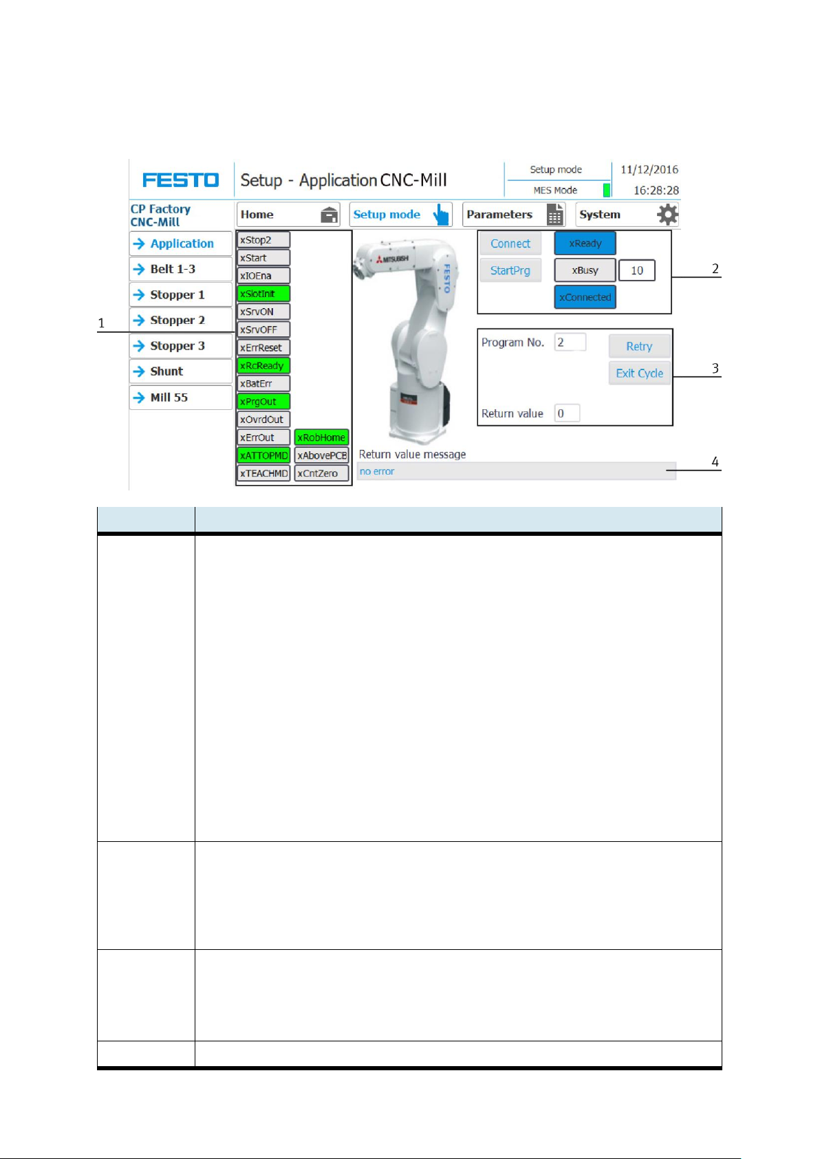
Position number
description
1
Display robot inputs (green if active)
xStop2 - movement stopped
xStart - motion started
xIOEna - the robot is controlled by an external controller
xSlotInit - Slot 1 of the robot is initialized
xSrvON - Servo mode switched on
xSrvOFF - Servo mode switched off
xErrReset - Reset error
xRcReady - Drive Unit of the robot is ready
xBatErr - the battery of the robot is empty
xPrgOut - Program area outputs is selected
xOvrdOut - Override range Outputs is selected
xErrOut - the robot has an error
xATTOMPD - The robot is in automatic mode
XTEACHMID - the robot is in manual mode
XRobHome - the robot is in the home position
xAbovePCB - the robot is above the board
XCntZero - reset counter to zero
2
Control robot (blue if active)
Connect - connect to the Drive Unit
Start Prog. - start the robot program
xReady - the robot is ready
xBusy - the robot is busy (display current step)
xConnected - connection drive unit made
3
Program number - Program number as in the drive unit
PCB Pos. - Position of the board inside the box
Return value - Return value of the robot program
Repeat - try again
Exit Cycle - end the current cycle
4
Textual description of the return value
4.6.5 Operating mode Setup
Application – Mitsubishi robot
© Festo Didactic CP Factory ° Robot feeding for mill 69
Page 70
Operation
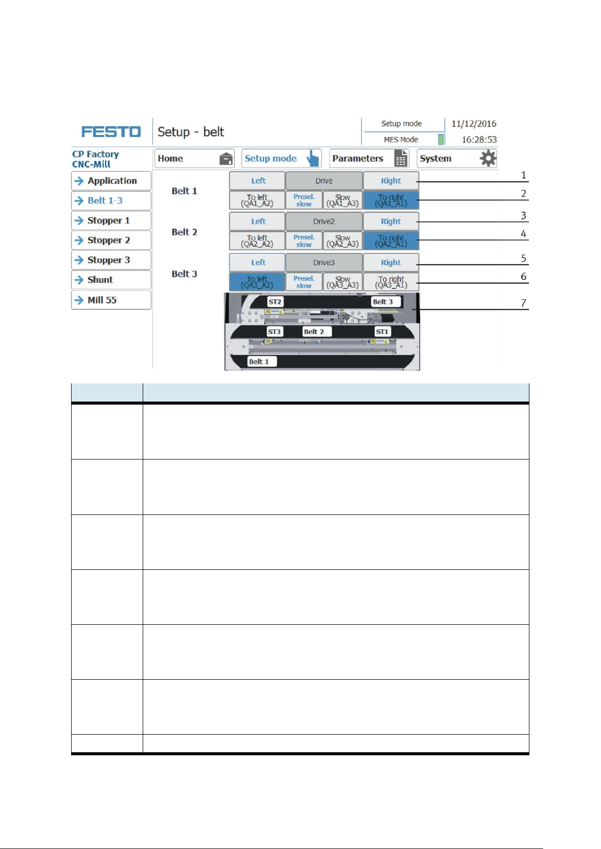
Position number
description
1
Drive conveyor 1 right / left
Left: Conveyor moves counterclockwise to the left
Drive 1: Display conveyor belt 1
Right: conveyor moves clockwise to the right
2
To left: move conveyor to the left (actuator QA1_A2 is activated, lights up blue when active)
Slow pre selection: set the conveyor speed slowly
Slow: move the conveyor slowly (actuator QA1_A3 is activated, lights up blue when active)
To right: move conveyor to the right (actuator QA1_A1 is activated, lights up blue when active)
3
Drive conveyor 2 right / left
Left: Conveyor moves counterclockwise to the left
Drive 2: Display conveyor belt 2
Right: conveyor moves clockwise to the right
4
To left: move conveyor to the left (actuator QA2_A2 is activated, lights up blue when active)
Slow pre selection: set the conveyor speed slowly
Slow: move the conveyor slowly (actuator QA2_A3 is activated, lights up blue when active)
To right: move conveyor to the right (actuator QA2_A1 is activated, lights up blue when active)
5
Drive conveyor 3 right / left
Left: Conveyor moves counterclockwise to the left
Drive 3: Display conveyor belt 3
Right: conveyor moves clockwise to the right
6
To left: move conveyor to the left (actuator QA3_A2 is activated, lights up blue when active)
Slow pre selection: set the conveyor speed slowly
Slow: move the conveyor slowly (actuator QA3_A3 is activated, lights up blue when active)
To right: move conveyor to the right (actuator QA3_A1 is activated, lights up blue when active)
7
Display conveyors and stoppers (light up green when active)
Setup – belt 1-3
70 © Festo Didactic CP Factory ° Robot feeding for mill
Page 71
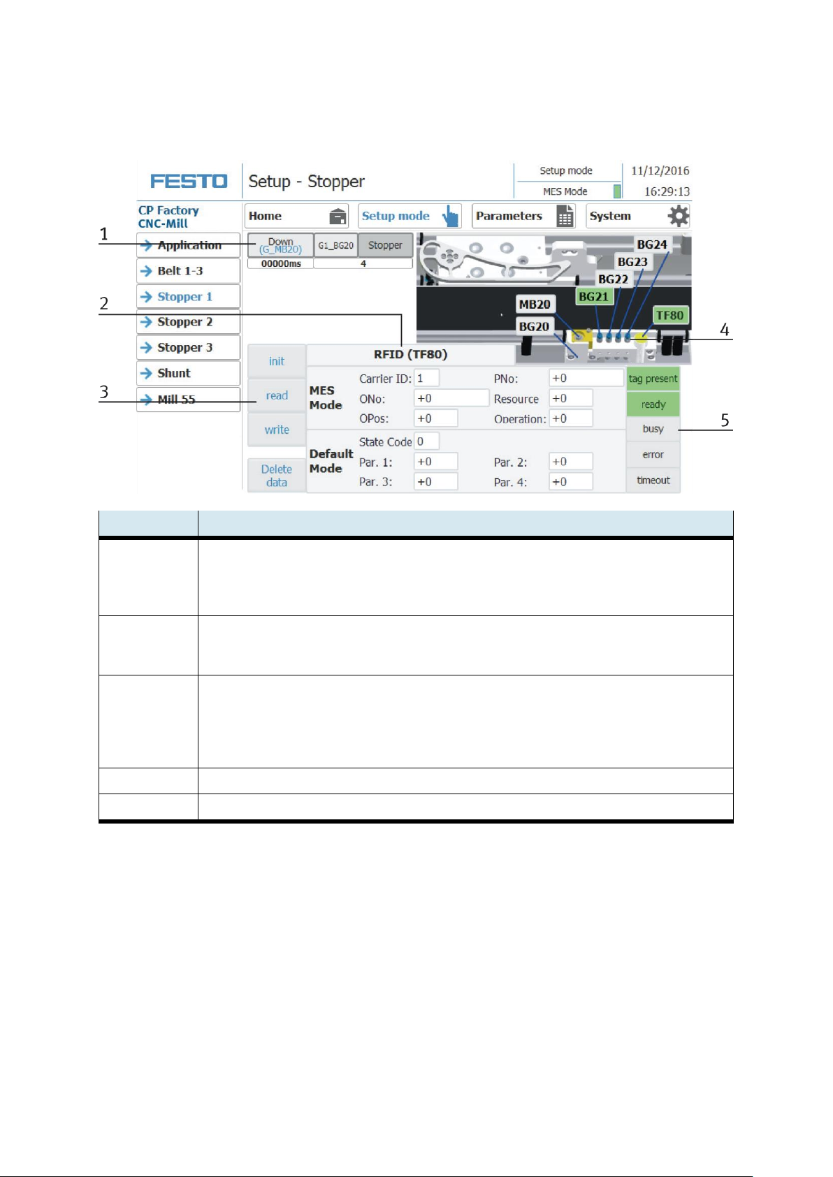
Operation
Position number
description
1
Shut down stopper
down: Move stopper downwards (actuator G_MB20 is activated, lights up blue when active)
G1_BG20: Sensor G1_BG20 stopper down (lit green when active)
Stopper: display stopper
2
Area RFID
MES Mode: Display of order data
Default Mode: Display of the RFID state
3
Describe and read the RFID area
initialize: set RFID data to zero
read: Read out RFID data
write: write current data on RFID
Delete data: all data in the input mask is deleted - not directly on the RFID (for easier entry)
4
Area Display of the active sensors (lit green when active) and actuators (lit orange if active) on the stopper
5
Display of the RFID read status
Setup – Stopper 1
© Festo Didactic CP Factory ° Robot feeding for mill 71
Page 72
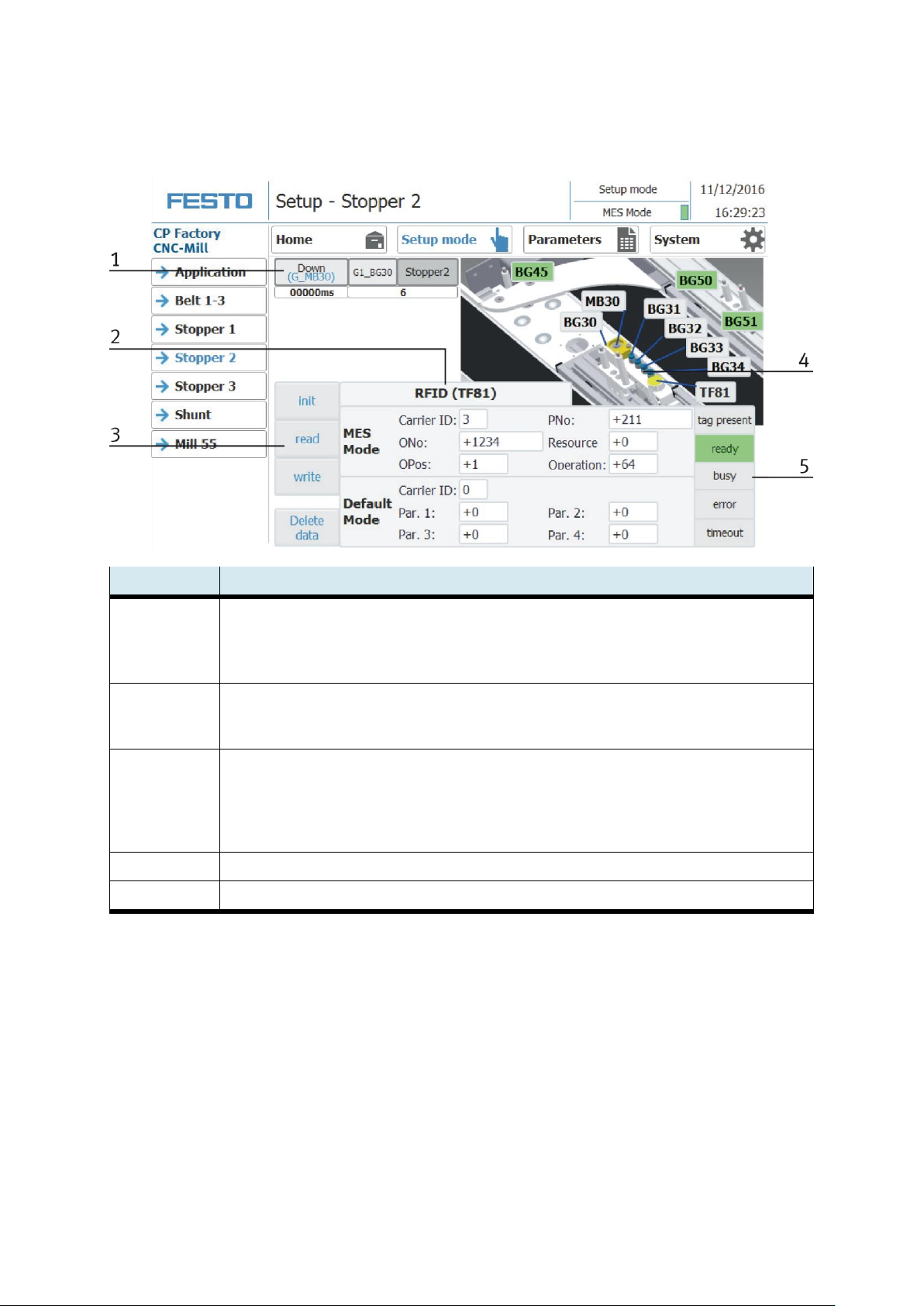
Operation
Position number
description
1
Shut down stopper
down: Move stopper downwards (actuator G_MB30 is activated, lights up blue when active)
G1_BG30: Sensor G1_BG30 stopper down (lit green when active)
Stopper: display stopper
2
Area RFID
MES Mode: Display of order data
Default Mode: Display of the RFID state
3
Describe and read the RFID area
initialize: set RFID data to zero
read: Read out RFID data
write: write current data on RFID
Delete data: all data in the input mask is deleted - not directly on the RFID (for easier entry)
4
Area Display of the active sensors (lit green when active) and actuators (lit orange if active) on the stopper
5
Display of the RFID read status
Setup – Stopper 2
72 © Festo Didactic CP Factory ° Robot feeding for mill
Page 73
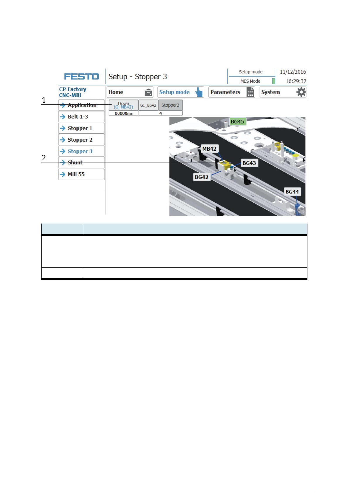
Operation
Position number
description
1
Shut down stopper
down: Move stopper downwards (actuator G_MB42 is activated, lights up blue when active)
G1_BG42: Sensor G1_BG42 stopper down (lit green when active)
Stopper: display stopper
2
Area Display of the active sensors (lit green when active) and actuators (lit orange if active) on the stopper
Setup – Stopper 3
© Festo Didactic CP Factory ° Robot feeding for mill 73
Page 74
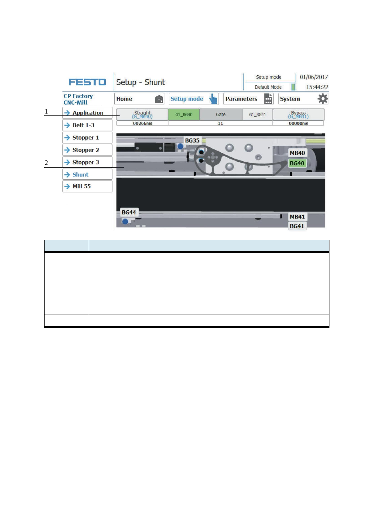
Operation
Position number
description
1
operate Shunt
Straight: set the shunt to straight (Actuator G_MB40 is activated, lights blue when active)
G1_BG40: Sensor G1_BG40 Shunt straight into position (lights up green when active)
Gate: Display shunt
G1_BG41: Sensor G1_BG41 Turn shunt to Bypass position (lit green when active)
Bypass: turn shunt to bending / bypass (Actuator G_MB41 is activated, lights blue if active)
2
Area Display of the active sensors (lit green when active) and actuators (lit orange if active) on the stopper
Setup – Shunt
74 © Festo Didactic CP Factory ° Robot feeding for mill
Page 75
Operation
Position number
Description
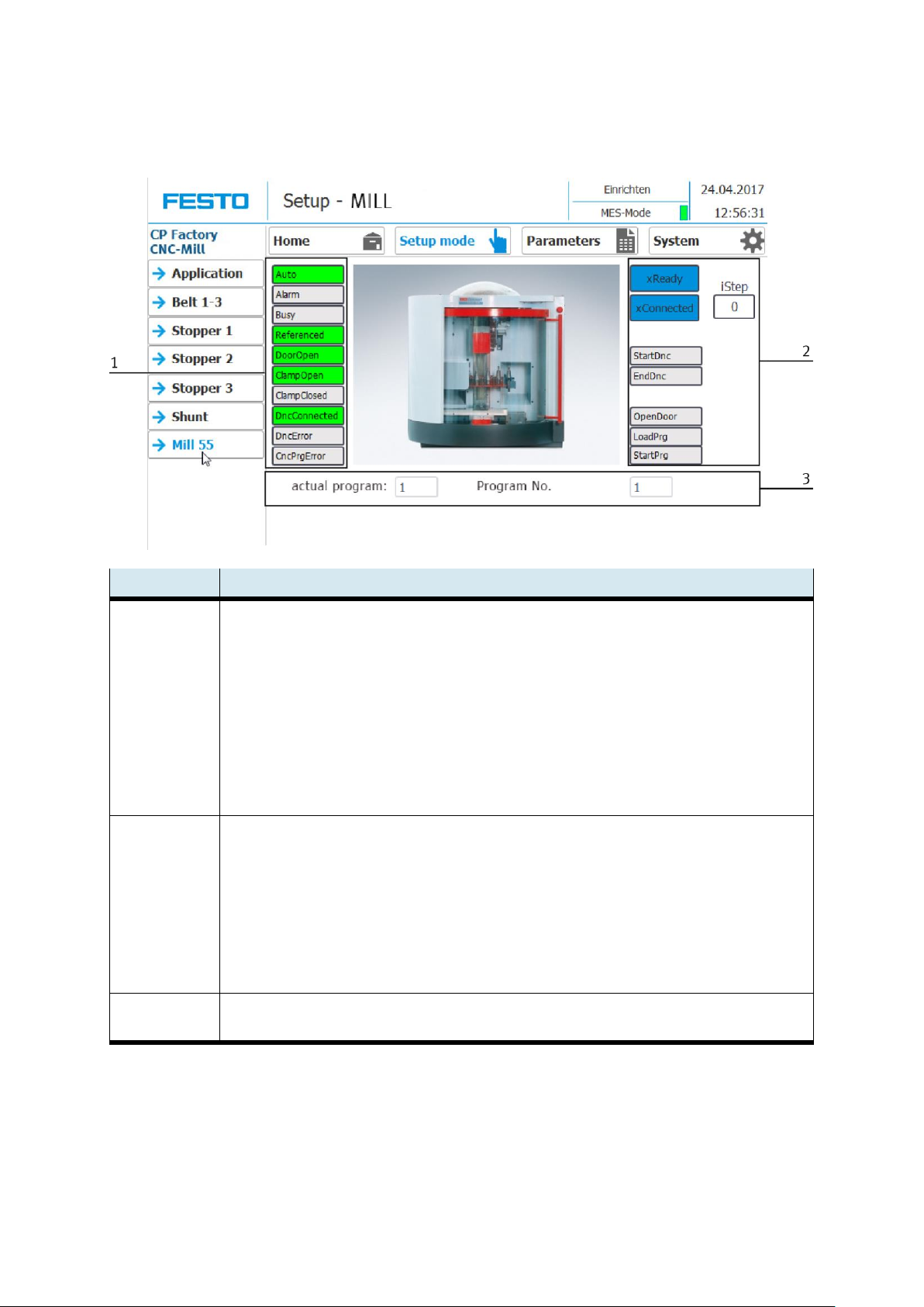
1
Display input milling machine (green when active)
Auto – milling machine in automatic mode
Alarm – error at milling machine alarm active
Busy – milling machine busy
Referenced – milling machine has made the reference move
DoorOpen – door at milling machine is opened
ClampOpen – vice at milling machine is opened
ClampClosed – vice at milling machine is closed
DncConnected – connection to DNC controller is established
DncError – connection to DNC controller is faulty
CncPrgError – CNC program is faulty
2
Status display of milling machine (blue when active)
xReady – milling machine is ready
xConnected – connection to milling machine is established
iStep – display of step number from actual sequence
StartDnc –connect to DNC controller
EndDnc – disconnect DNC controller
OpenDoory – open door of milling machine
LoadPrg – load program at milling machine
StartPrg – execute program milling machine
3
Actual program - display
Program No. - display
Mill 55
© Festo Didactic CP Factory ° Robot feeding for mill 75
Page 76
Operation
4.6.6 Operation mode Parameters
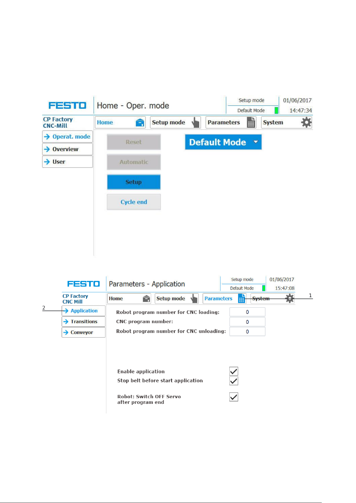
Set parameters of the application module on the HMI
To set up the application module, the application module must be set to setup mode.
1. On the Start screen, click Setup
2. Change to parameter page (1) and select application (2).
76 © Festo Didactic CP Factory ° Robot feeding for mill
Page 77
Operation
Position number
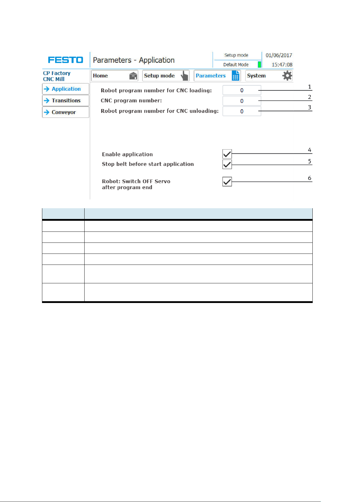
Description
1
Robot program number for CNC loading : here the program number for loading the CNC machine is announced
2
CNC program number: here the CNC program is announced
3
Robot program number for CNC loading : here the program number for unloading the CNC machine is announced
4
Enable application: Here, a tick is set to activate the application
5
Stop the belt before the application starts: The conveyor is stopped before the application starts to work - set
the hook for this
6
Robot: Switch off Servo after program end: set hook to switch off the Servos of the robot after a program is
ended
© Festo Didactic CP Factory ° Robot feeding for mill 77
Page 78
Operation
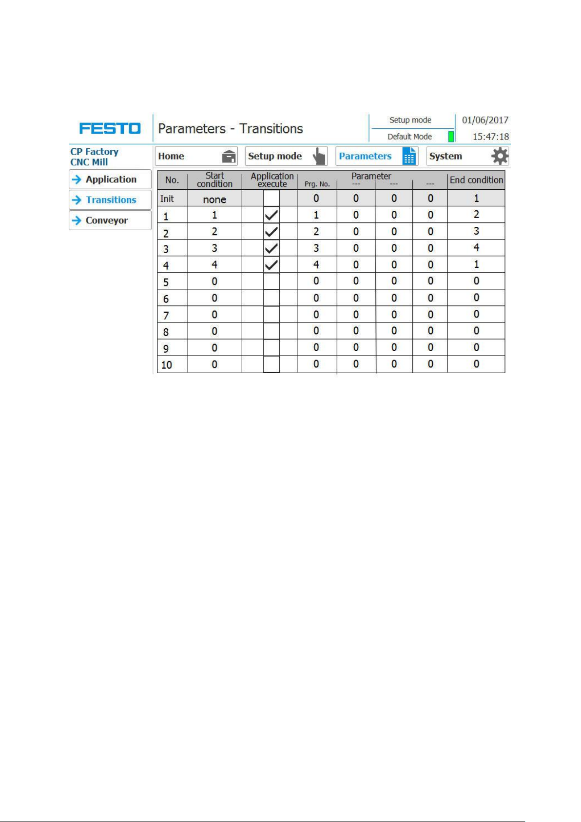
Sub menu - Transitions
78 © Festo Didactic CP Factory ° Robot feeding for mill
Page 79
Operation
Position number
description
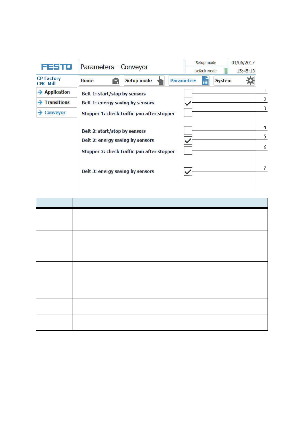
1
Belt 1 Start / Stop by sensors: Hook set when the belt should be switched automatically with the sensors.
Switch on when Sensor at belt beginning signals a carrier, switch off when the sensor at the end of the belt
signals the carrier passing by
2
Belt 1 energy saving mode with sensors:
If no workpiece is detected on the belt via the sensors, the belt is switched off
3
Stopper 1: Check the jam at the belt outlet:
The carrier is only released from the stopper if the belt is not occupied at the belt outlet.
4
Belt 2 Start / Stop by sensors: Hook set when the belt should be switched automatically with the sensors.
Switch on when Sensor at belt beginning signals a carrier, switch off when the sensor at the end of the belt
signals the carrier passing by
5
Belt 2 energy saving mode with sensors:
If no workpiece is detected on the belt via the sensors, the belt is switched off
6
Stopper 2: Check the jam at the belt outlet:
The carrier is only released from the stopper if the belt is not occupied at the belt outlet.
7
Belt 3 energy saving mode with sensors:
If no workpiece is detected on the belt via the sensors, the belt is switched off
Sub menu application
© Festo Didactic CP Factory ° Robot feeding for mill 79
Page 80
Operation
Position number
Description
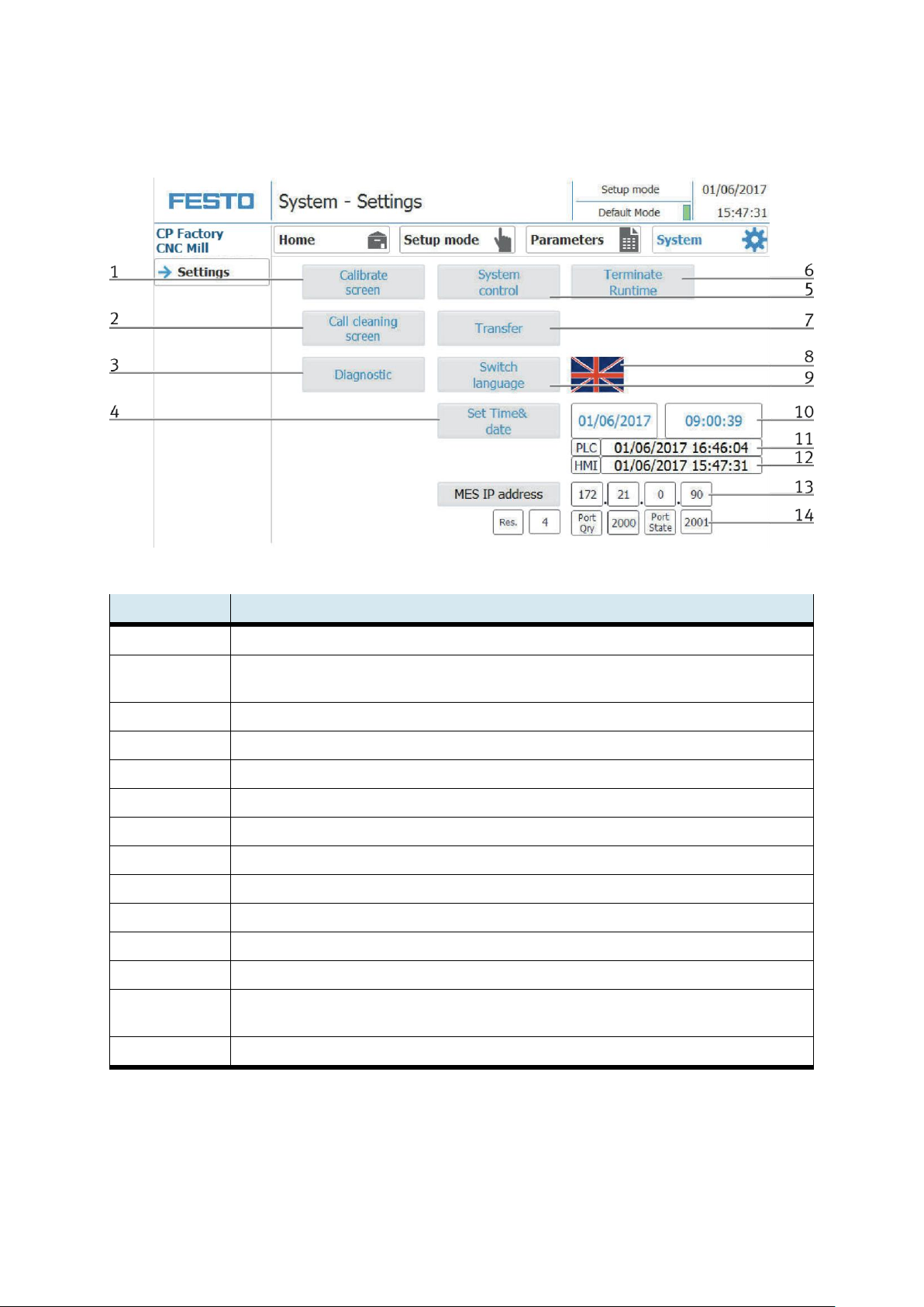
1
Button Calibrate Screen - If buttons react inaccurately, calibration of the touch screen can be restored
2
Button call cleaning screen - the screen can be cleaned here. The touch function is interrupted and
unintentional operation is excluded
3
Button Diagnostics - Call up the PROFINET diagnostics
4
Button set time & date: The time and date of the HMI touch panel can be set here.
5
Terminate Runtime: The runtime is terminated and returned to Windows.
6
Button Open system control: Windows system control is opened
7
Button Transfer: Runtime is closed and the transfer mode of the HMI is called
8
Flag displays only current language. By clicking on button next to the flag language can be switched
9
Button language: here the language can be changed
10
Input field for date / time. Click on the "Set time & date" button to accept date / time
11
Display date and time of the PLC
12
Display date and time of the HMI touch panel
13
Display of the MES IP address additionally the IP of the MES can be set here. (Password protected) User: festo,
PW: festo)
14
Input fields for your own resource number, query port and status port of the MES connection
4.6.7 Operation mode System - settings
The system can be set in this operation mode
80 © Festo Didactic CP Factory ° Robot feeding for mill
Page 81
Operation
4.7 Automatic operation
4.7.1 Start automatic
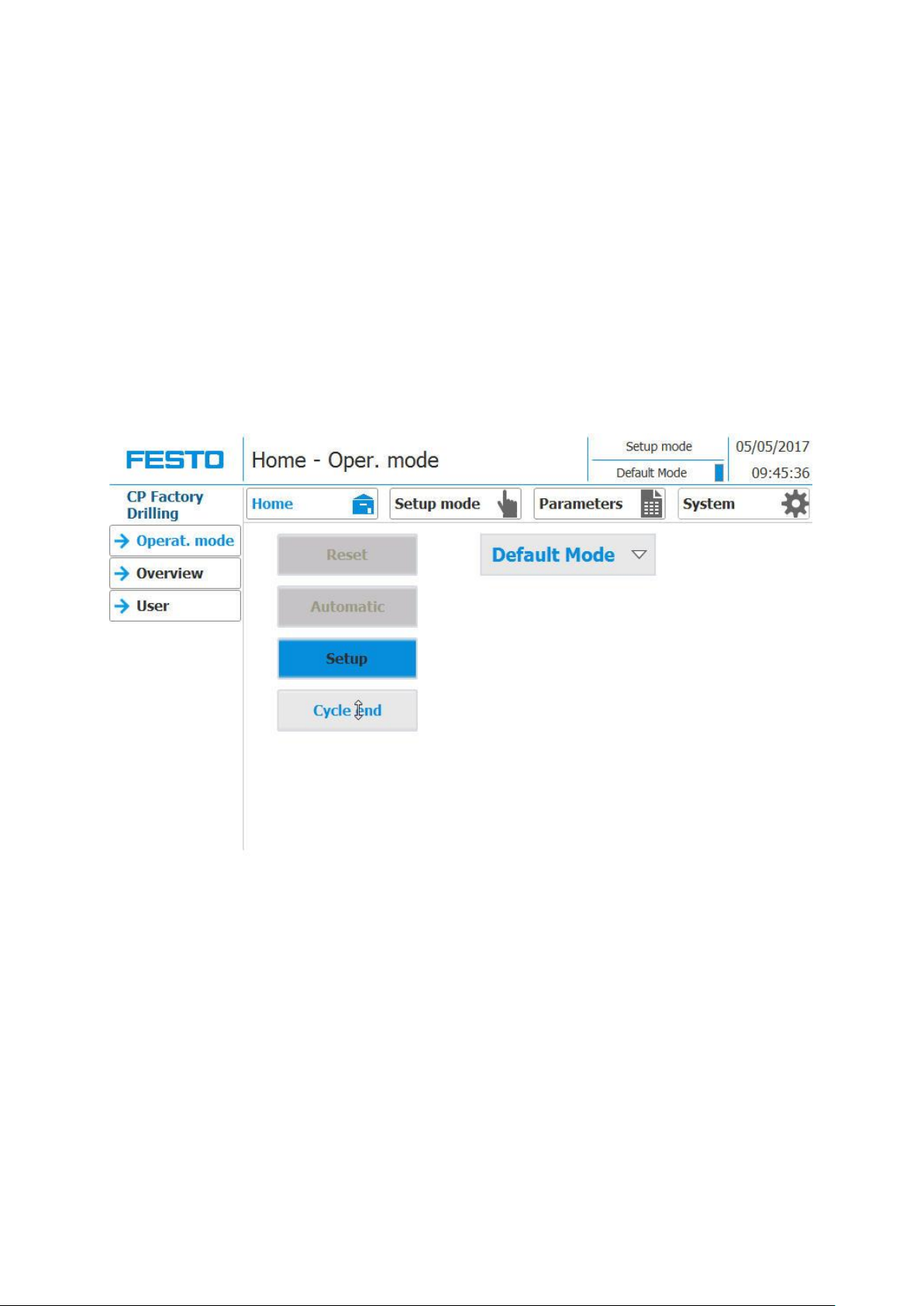
The operation is the same for all application modules and modules, for the description the basic module is
used with an application module Drilling.
The general rule:
A blinking button is a prompt to start an action.
A button with a glowing background indicates that the action described on the button is currently being
executed.
A gray button with a blue font indicates that this function is selectable.
1. Switch on the station and wait until HMi is raised. The following screen appears
2. Press Setup button
© Festo Didactic CP Factory ° Robot feeding for mill 81
Page 82
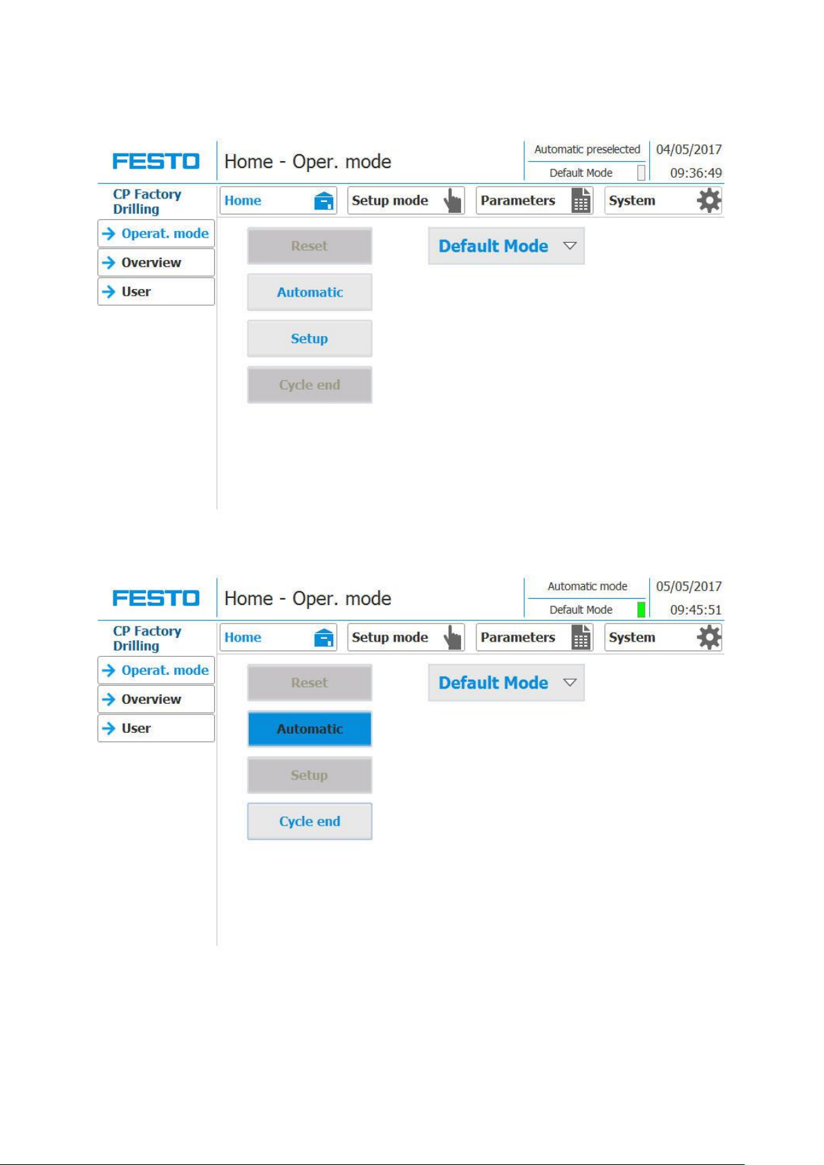
Operation
3. Select the default or MES mode, for the example the default mode is selected
4. Press the automatic button
5. Automatic is active
82 © Festo Didactic CP Factory ° Robot feeding for mill
Page 83
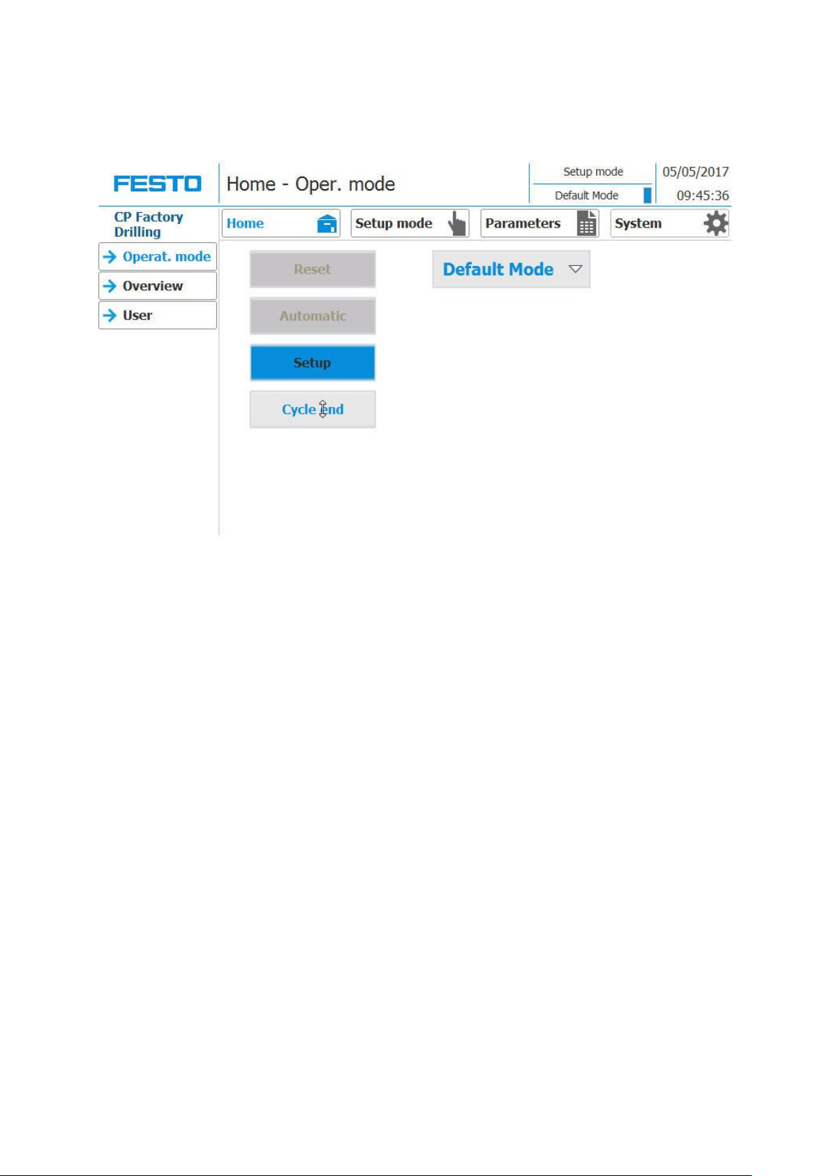
Operation
4.7.2 Stop automatic
1. Press the cycle end button, the automatic sequence is immediately stopped.
© Festo Didactic CP Factory ° Robot feeding for mill 83
Page 84
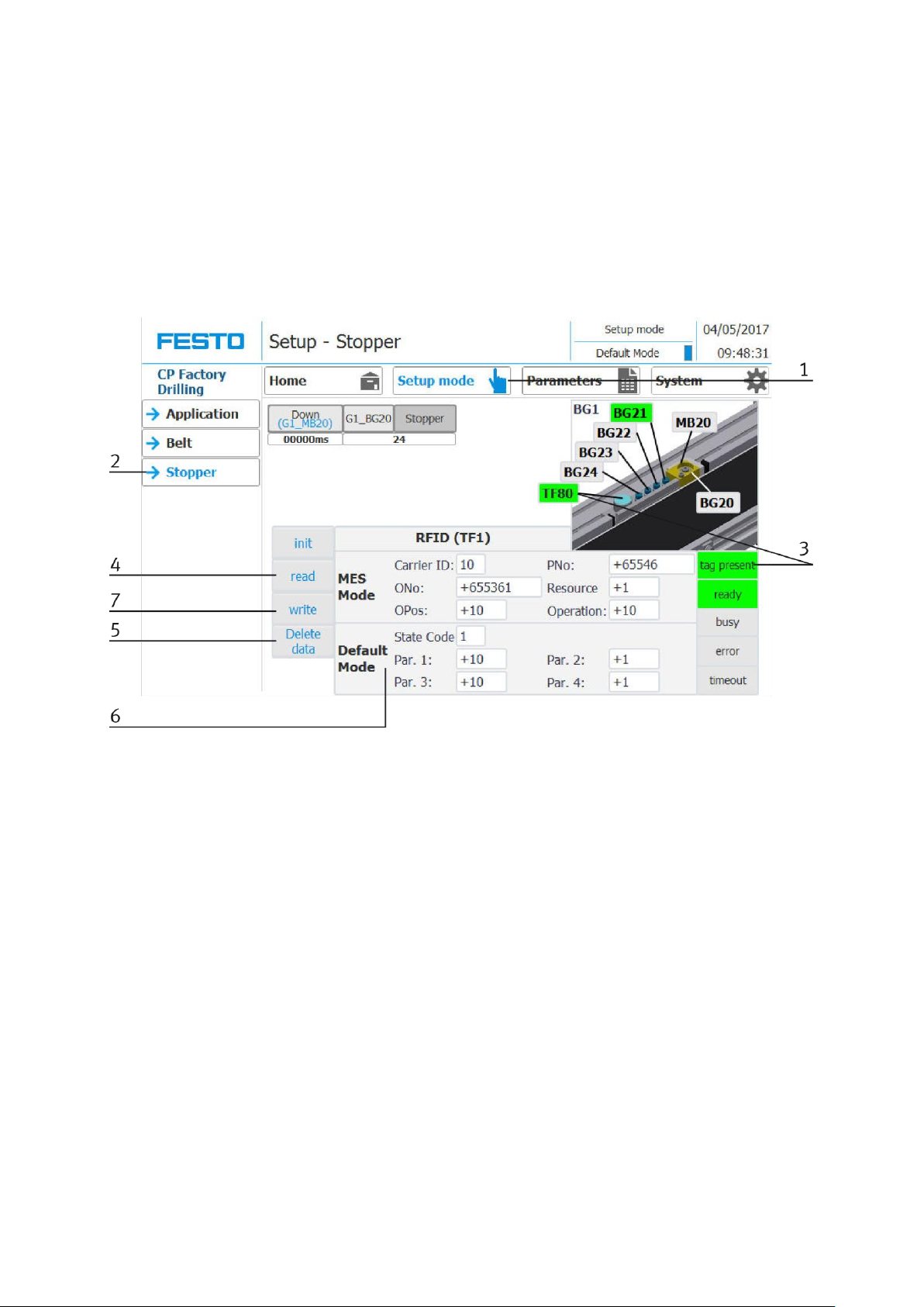
Operation
4.8 Writing on the RFID tag manually
4.8.1 Pallet carriers
In order to describe a pallet carrier with a specific ID, or to get information on which data is stored on the
pallet carrier, it is possible to read this data or to describe the tag.
For this, it is necessary that a pallet carrier with a functioning tag is at one of the stopper positions and the
station is switched on.
The following example is guilty for all read out positions where pallet carriers can be read out.
1. Select the Setup mode
2. Select the stopper from the setup menu on the left
3. If an RFID is detected, this is indicated by "tag present". (TF80 and button "tag present" are green)
4. The data of the RFID tag can be read out and displayed by pressing the "read" button.
5. Press the Delete Data button
For easier input, all data is only deleted in the input mask, the data remains on the tag itself.
84 © Festo Didactic CP Factory ° Robot feeding for mill
Page 85

Operation
6. Enter the desired data in the field (all fields which are white in background can be edited)
MES Mode
Carrier ID - displays or enter the carrier number
ONo - the order number is displayed or entered here
OPos - the order position is displayed or entered here
PNo - the part number is displayed or entered here
Resource - here the resource is displayed or entered
Operation - the number of the operation is displayed or entered here
DefaultMode
State code - here the state code for the start condition is entered, if these match the transition tables,
the parameters are read out and the automatic sequence of the application is started.
Parameter 1 = 1 - Input of the 1 parameter value (e.g., 1 / left side drilling)
Parameter 1 = 2 - Enter the 2 parameter value (e.g., 2 / right side drilling)
Parameter 1 = 3 - Input of the 3 parameter value (e.g., 3 / both sides drilling)
Parameters 2 - 4 - not used in this example
7. Press the "Write" button to write the changes made to the tag.
© Festo Didactic CP Factory ° Robot feeding for mill 85
Page 86
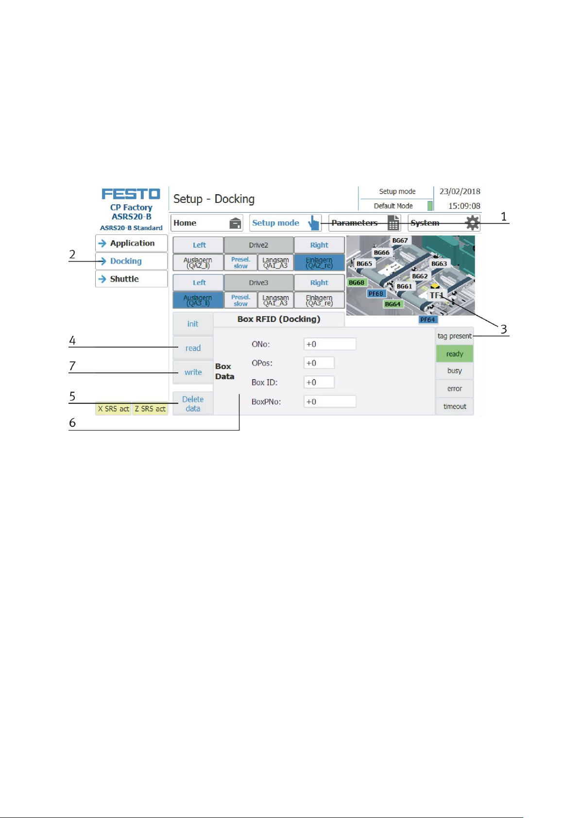
Operation
4.8.2 Boxes
In order to describe a box with a certain ID, or to get information about what data is on the box, it is possible
to read this data or to describe the tag.
For this it is necessary that a box with a working tag is located at one of the readout positions and the
station is switched on.
The following example applies to all readout positions that can read an ID of boxes.
1. Select the Setup mode
2. Select the module with the read out position from the menu on the left
3. If an RFID is detected, this is indicated by "tag present". (TFxx and button "tag present" are green)
4. The data of the RFID tag can be read out and displayed by pressing the "read" button.
5. Press the Delete Data button
For easier input, all data is only deleted in the input mask, the data remains on the tag itself.
6. Entry of the desired data in the field (all fields with a white background can be edited)
MES Mode and default mode are identically
ONo – without function
OPos – without function
BoxID – here the IB number of the box is displayed or entered
BoxPNo – Here, the part number of the box and the retainer for the workpieces to be picked up are
displayed or entered.
7. Press the „write“ button in order to write the performed modifications on the tag.
86 © Festo Didactic CP Factory ° Robot feeding for mill
Page 87
Operation
Parameter-Number
Description
1
Program number for loading [-]
1: load CNC with workpiece (robot)
Limitation: No limitation of the value in the transition table
2
CNC Program number [-]
1: process workpiece (CNC)
Limitation: No limitation of the value in the transition table
3
Program number for unloading [-]
2: Remove workpiece from CNC (robot)
Limitation: No limitation of the value in the transition table
4
Not used
Operation
Parameter-
Number
Description
No.
No.
Name
193
Start robot and
mill
1
Program number loading [-]
Limitation: No limitation, Value: 1, changeable
2
Program number CNC [-]
Limitation: No limitation, Value: 1, changeable
3
Program number unloading [-]
Limitation: No limitation, Value: 2, changeable
4
Processing time [s]
Limitation: none, value: 5s, changeable
Note: This parameter is only included in the internal time calculation of the work plan and has
no effect on the error handling of the station.
4.8.3 Parameter CP Factory feeding robot and mill
Default:
MES:
© Festo Didactic CP Factory ° Robot feeding for mill 87
Page 88
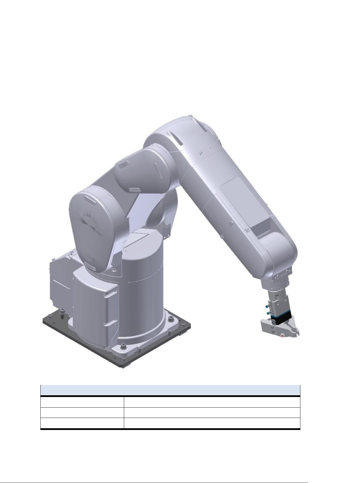
Components
Performance
Inputs
32 Inputs for communication
Outputs
32 Outputs for communication
Max. reservation
1 work piece/pallet
5 Components
5.1 Mitsubishi Robot RV-4FL
For the transport of the workpieces, a vertical- articulated arm robot is used. This is an industrial robot with
6 axis. The repetition accuracy of the robot positioning is
0.02mm. Its maximum speed amounts to 9900 mm/s. There is an end position and overload monitoring
programme integrated. The maximum reach of the robot arm is 648,7 mm.
RV-4FL
88 © Festo Didactic CP Factory ° Robot feeding for mill
Page 89
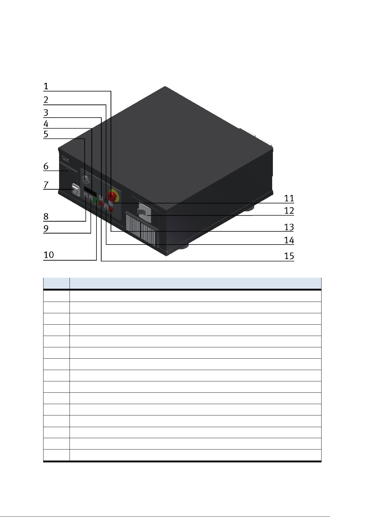
Components
Position
Description
1
Emergency stop
2
Down button
3
CHNG button
4
Display
5
Key switch for teach or auto modes
6
Interface cover for USB and battery
7
Plug for teach pendant
8
Servo on button
9
Servo off button
10
Start button
11
Up button
12
Main switch
13
END button
14
RESET button
15
Stop button
5.1.1 Drive Unit CR750-D
The Drive Unit is the controller for the robot.
© Festo Didactic CP Factory ° Robot feeding for mill 89
Page 90
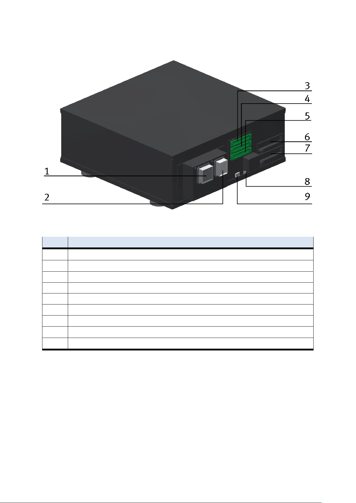
Components
Position
Description
1
CN1 for robot communication
2
CN2 for robot communication
3
CNUSER 11
4
CNUSER 12
5
CNUSER 13
6
Slot 1 / for connector 1 (in/output 0-15)
7
Slot 2 / for connector 2 (in/output 16-31)
8
CNUSER 2
9
LAN1 for ethernet
On the backside of the drive unit, there are some more plugs and interfaces.
90 © Festo Didactic CP Factory ° Robot feeding for mill
Page 91
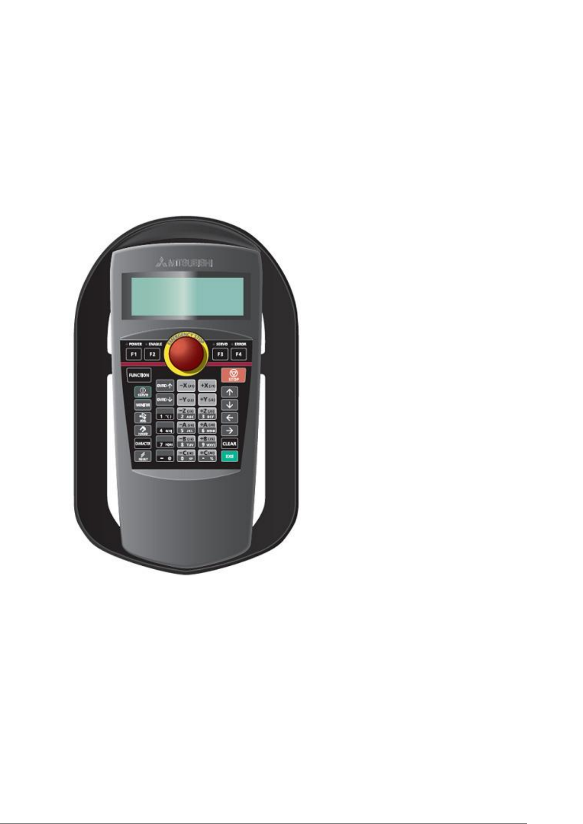
Components
5.1.2 Teach pendant R32TB
The Teach pendant is required in order to be able to use the robot in the stand alone mode. There are
different functions of the buttons depending on the mode of operation selected. You can choose the
following two different modes by the key actuator on the Drive Unit.
Auto position (OP) for the stand alone mode
Auto position (EXT) for the communication with other controls
Teach position for the Teach mode.
Teachpendant
© Festo Didactic CP Factory ° Robot feeding for mill 91
Page 92
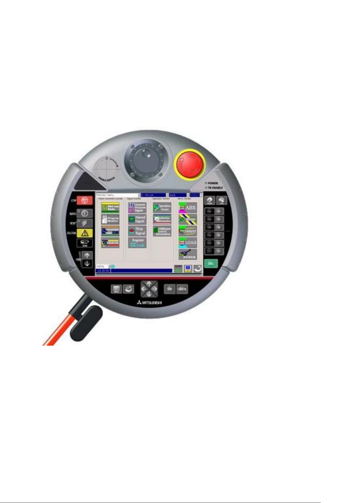
Components
5.1.3 Teachpendant R56TB
To operate the robot in standalone mode, the teach pendant is necessary. The buttons have different
functions, depending on the different modes. With the key switch at the Drive unit, it is possible to choose
the following three modes.
Position Auto (OP) for standalone mode.
Position Auto (EXT) for communication with other controller.
Position Teach for teach mode.
Teachpendant
92 © Festo Didactic CP Factory ° Robot feeding for mill
Page 93
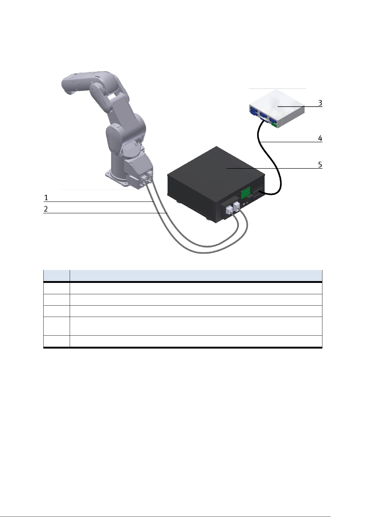
Components
Position
Description
1
CN1 cabel
2
CN 2 cabel
3
Drive Unit CR750-D
4
50 Pin cable from Ria-Box to slot 1 / there is a special cable necessary, this cable is plugged at the Drive Unit and then
connected to the 50 PIN cable
5
RIA Box
5.1.4 Set up
Robot RV4-FL set up example for standalone mode
© Festo Didactic CP Factory ° Robot feeding for mill 93
Page 94
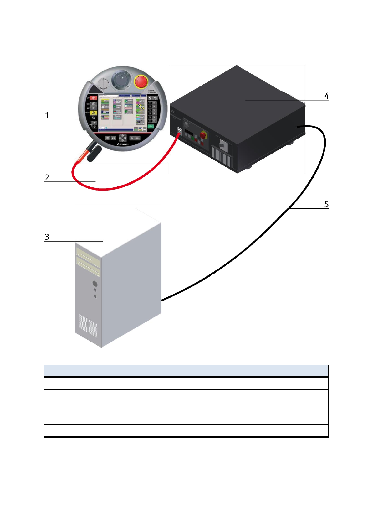
Components
Position
Description
1
TB 2 Cable to Drive Unit
3
Programming PC
4
Drive Unit CR750D
5
Cable to Ethernet interface
Robot RV4-FL set up example for standalone mode
94 © Festo Didactic CP Factory ° Robot feeding for mill
Page 95
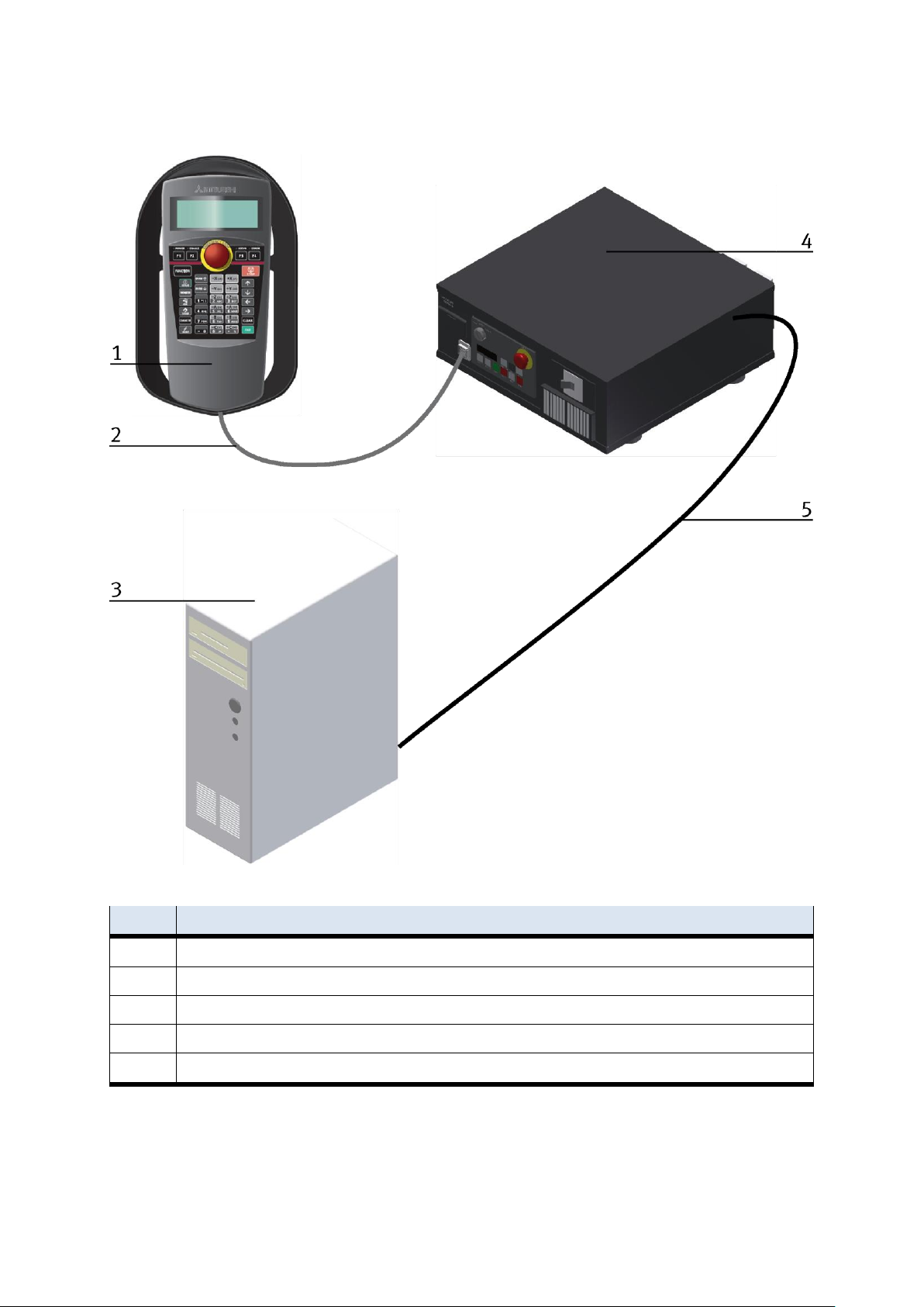
Components
Position
Description
1
TB 2 Cable to Drive Unit
3
Programming PC
4
Drive Unit CR750D
5
Cable to Ethernet interface
Robot RV4-FL set up example for standalone mode
© Festo Didactic CP Factory ° Robot feeding for mill 95
Page 96

Components
Sensor Name
RV-4FL Robot
SIEMENS
PLC
Variable Name
Input/
Output
Robot
address
Data
Type
Comment
PLC
Address
connected to robot IO card
CNC
DoorOpened
Input
16
Bit
Milling machine door opened
CNC
DoorClosed
Input
17
Bit
Milling machine door closed
CNC
ViceOpened
Input
18
Bit
Milling machine vice opened
CNC
ViceClosed
Input
19
Bit
Milling machine vice closed
CNC
CNCRefPose
Input
20
Bit
Milling machine in reference position
CNC
CNCStopped
Input
21
Bit
Milling machine program is stopped
CNC
CNCInError
Input
22
Bit
Milling machine error in status
Robot
status
Info
region
#STOP2
Input
2000
Bit
Stop
100.0
#START
Input
2001
Bit
Program started
100.1
#IOENA
Input
2002
Bit
Set operation rights enable
100.2
#SLOTINIT
Input
2003
Bit
Reset program
100.3
#SRVON
Input
2004
Bit
Servo power supply on
100.4
#SRVOFF
Input
2005
Bit
Servo power supply off
100.5
#ERRRESET
Input
2006
Bit
Reset error input signal
100.6
#PRGSEL
Input
2007
Bit
Choose program input signal
100.7
#OVRDSEL
Input
2008
Bit
Choose override input signal
101.0
#PRGOUT
Input
2009
Bit
Program number output request
101.1
#OVRDOUT
Input
2010
Bit
Override value request
101.2
#ERROUT
Input
2011
Bit
Error number output request
101.3
#Reserved
Input
2012 2015
Reserved
#IODATA
Input
2016 2031
Word
Numeric value input
102 - 103
DI_RetryLastSt
ep
Input
2032
Bit
Retry last step
104,0
DI_ExitCurrCyc
le
Input
2033
Bit
Exit current program cycle
104,1
Reserve_RobS
tate1
Input
2034 2039
Reserved for extension
Reserve_RobS
tate2
Input
2040 2047
Byte
Reserved for extension
105
5.1.5 Interface Drive Unit
96 © Festo Didactic CP Factory ° Robot feeding for mill
Page 97

Components
Sensor Name
RV-4FL Robot
SIEMENS
PLC
Robot
Variable
Info
Region
ReservedWord1
Input
2048 - 2063
Word
Reserved Word 1
106 - 107
ReserveByte1
Input
2064 - 2071
Byte
Reserved Byte 1
108
ReserveByte2
Input
2072 - 2079
Byte
Reserved Byte 2
109
ReserveByte3
Input
2080 - 2087
Byte
Reserved Byte 3
110
ReserveByte4
Input
2088 - 2095
Byte
Reserved Byte 4
111
ReserveByte5
Input
2096 - 2103
Byte
Reserved Byte 5
112
ReserveByte6
Input
2104 - 2111
Byte
Reserved Byte 6
113
ReserveByte7
Input
2112 - 2119
Byte
Reserved Byte 7
114
ReserveByte8
Input
2120 - 2127
Byte
Reserved Byte 8
115
ReserveByte9
Input
2128 - 2135
Byte
Reserved Byte 9
116
ReserveByte10
Input
2136 - 2143
Byte
Reserved Byte 10
117
Connected
PLC card
BG50
DI_WPPalAvail
Input
2144
Bit
Workpiece pallet is available
118,0
BG51
DI_WPAtStopAvail
Input
2145
Bit
Workpiece at stopper position
118,1
ReserveSensor1
Input
2146 - 2151
Bit
Reserved for sensor group 1
ReserveSensor2
Input
2152 - 2159
Byte
Reserved for sensor group 2
119
ReserveSensor3
Input
2160 - 2167
Byte
Reserved for sensor group 3
110
ReserveSensor4
Input
2168 - 2175
Byte
Reserved for sensor group 4
111
Connected with robot I/O card
CNC
StartNCPrg
Output
24
Bit
Start loaded CNC program
CNC
StopCNC
Output
25
Bit
Stop CNC program
CNC
OpenDoor
Output
26
Bit
Open door of CNC machine
CNC
CloseDoor
Output
27
Bit
Close door of CNC machine
CNC
OpenVice
Output
28
Bit
Open vice of CNC machine
CNC
CloseVice
Output
29
Bit
Close vice of CNC machine
© Festo Didactic CP Factory ° Robot feeding for mill 97
Page 98

Components
Sensor Name
RV-4FL Robot
SIEMENS PLC
Robot
Status
Info
Region
#STOP2
Output
2000
Bit
Stop
100.0
#START
Output
2001
Bit
Start program
100.1
#IOENA
Output
2002
Bit
Set operation rights enable
100.2
#SLOTINIT
Output
2003
Bit
Enable choose program
100.3
#SRVON
Output
2004
Bit
Servo on
100.4
#SRVOFF
Output
2005
Bit
Servo off
100.5
#ERRRESET
Output
2006
Bit
Output signal for errors
100.6
#RCREADY
Output
2007
Bit
Controller ready
100.7
#BATERR
Output
2008
Bit
Power supply is missing
101.0
#PRGOUT
Output
2009
Bit
Program number output signal
101.1
#OVRDOUT
Output
2010
Bit
Override value output signal
101.2
#ERROUT
Output
2011
Bit
Error number output signal
101.3
#ATTOPMD
Output
2013
Bit
Teachmode output
101,5
#TEACHMD
Output
2014
Bit
Teachmode output
101,6
#IODATA
Output
2016 2031
Word
Numeric value output
102 - 103
IsRbtArmHome
Output
2032
Bit
Robot arm in basic position
104,0
IsRbtArmInByP
ass
Output
2033
Bit
Robot arm over bypass
104,1
IsRbtArmInMill
Output
2034
Bit
Robot arm inside milling machine
104,2
Reserve_RobS
tate1
Output
2035 2039
Reserved for robot status
Reserve_RobS
tate2
Output
2040 2047
Byte
Reserved for extension
105
Robot
Variable
Info
Region
ReservedWord
1
Output
2048 2063
Word
Reserved Word 1
106 - 107
ReturnValue
Output
2064 2071
Byte
Return value robot
108
ReserveByte1
Output
2072 2079
Byte
Reserved Byte 1
109
ReserveByte2
Output
2080 2087
Byte
Reserved Byte 2
110
ReserveByte3
Output
2088 2095
Byte
Reserved Byte 3
111
ReserveByte4
Output
2096 2103
Byte
Reserved Byte 4
112
ReserveByte5
Output
2104 2111
Byte
Reserved Byte 5
113
98 © Festo Didactic CP Factory ° Robot feeding for mill
Page 99

Components
Sensor Name
RV-4FL Robot
SIEMENS PLC
ReserveByte6
Output
2112 2119
Byte
Reserved Byte 6
114
ReserveByte7
Output
2120 2127
Byte
Reserved Byte 7
115
ReserveByte8
Output
2128 2135
Byte
Reserved Byte 8
116
ReserveByte9
Output
2136 2143
Byte
Reserved Byte 9
117
CNC
DO_CNCAutoM
ode
Output
2144
Bit
CNC machine in automatic mode
118,0
CNC
DO_CNCPrgRu
ning
Output
2145
Bit
Program in CNC machine is
running
118,1
CNC
DO_CNCDoorO
pen
Output
2146
Bit
CNC door opened
118,2
CNC
DO_CNCViceO
pen
Output
2147
Bit
CNC vice opened
118,3
ReserveSensor
1
Output
2148 2151
Reserved for sensor group 1
ReserveSensor
2
Output
2104 2011
Byte
Reserved for sensor group 2
119
ReserveSensor
3
Output
2160 2167
Byte
Reserved for sensor group 3
110
ReserveSensor
4
Output
2168 2175
Byte
Reserved for sensor group 4
111
© Festo Didactic CP Factory ° Robot feeding for mill 99
Page 100

Components
5.1.6 Parameter
For the configuration of a new Drive Unit, you have to adjust the following parameters. After the
configuration, the Drive Unit has to be switched off and then switched on again.
Tool offsets:
MEXTL1= 0,0,205,0,0,0
MEXTL2= 0,0,170,0,0,0
MEXTL3= 0,0,151.50,0,0,0
MEXTL4= 0,0,0,0,0,0
Communication parameter DP
PBNUM=10;
STOP2=2000,2000;
START=2001,2001;
IOENA=2002,2002;
SLOTINIT=2003,2003;
SRVON=2004,2004;
SRVOFF=2005,2005;
ERRRESET=2006,2006;
PRGSEL=2007;
RCREADY=-1,2007;
OVRDSEL=2008;
BATERR=-1,2008;
PRGOUT=2009,2009;
OVRDOUT=2010,2010;
ERROUT=2011,2011;
ATTOPMD=-1,2013;
TEACHMD=-1,2014;
IODATA=2016,2031,2016,2031;
Communication parameter Ethernet Camera:
COMDEV=Us,"","OPT12","OPT13","","","","","";
NETHSTIP=Us,"192.168.0.2","192.168.0.3","Camera_IP_Address","192.168.0.5","192.168.0.6","192
.168.0.7","192.168.0.8","192.168.0.9","192.168.0.10";
NETPORT=10000, 10001, 10002, Camera_Port, 10004, 10005, 10006, 10007, 10008, 10009
NETMODE=Ud,1,1,0,1,1,1,1,1,1;
Slot Parameter:
SLT1=Us,"3","CYC","START","1";
SLT2=Us,"MONITORHOME","REP","ALWAYS","1";
SLT3=Us,"ENRGSAVEVACU","REP","ALWAYS","1";
SLT4=Us,"PCBTRAYCNTRL","REP","ALWAYS","1";
SLT5=Us,"MONITORPALWS","REP","ALWAYS","1";
100 © Festo Didactic CP Factory ° Robot feeding for mill
 Loading...