

Page 1
Controller
Description
System
description
Type
CMXR-C2
Description
571688
en 1205b
[7
61546]
Page 2

Page 3

Festo GDCP-CMXR-C2-SY-EN 1205b 3
Edition ____________________________________________________ en 1205b
Designation ________________________________ Festo GDCP-CMXR-C2-SY-EN
Order no. ___________________________________________________ 571688
Festo AG & Co KG., D-73726 Esslingen, Federal Republic of Germany, 2012
Internet: http://www.festo.com
E-mail: [email protected]
The copying, distribution and utilisation of this document as well as the communication of
its contents to others without express authorisation is prohibited. Offenders will be held
liable for compensation of damages. All rights reserved, in particular the right to file
patent, utility model or registered design applications.
Page 4

4 Festo GDCP-CMXR-C2-SY-EN 1205b
Index of revisions
Author:
Name of manual:
GDCP-CMXR-C2-SY-EN
File name:
File saved in:
Consec. no.
Description
Revisions index
Date of revision
001
Produced:
1002NH
21.03.2010
002
Revision
1011a
08.11.2010
003
Revision
1205b
2012-04-10
Trademarks
CANopen®, CiA® and PROFIBUS® are registered trademark owners in certain countries.
Page 5

Table of contents
Festo GDCP-CMXR-C2-SY-EN 1205b 5
Table of contents
1. Introduction .......................................................................................................... 8
1.1 Terminology used ................................................................................................ 8
1.2 Additional documents .......................................................................................... 9
2. Safety instructions .............................................................................................. 10
2.1 Using the documentation ................................................................................... 10
2.2 Recommended operating conditions .................................................................. 10
2.3 Qualified personnel ........................................................................................... 11
2.4 Safety instructions for this manual .................................................................... 11
2.5 Safety instructions for the products ................................................................... 11
2.6 Safety instructions for the product ..................................................................... 12
3. Modular multi-axis control system CMXR-C2 ...................................................... 14
3.1 Central control unit CMXR-C2 ............................................................................. 15
3.2 Memory card ..................................................................................................... 16
3.2.1 File system ......................................................................................... 17
3.2.2 Application directory .......................................................................... 18
3.3 CAN interfaces X4/ X6 ........................................................................................ 18
3.4 Ethernet interfaces X5/ X7 ................................................................................. 19
3.4.1 IP address on delivery ........................................................................ 19
3.5 USB interfaces X8/ X10 ...................................................................................... 19
3.6 Serial interfaces X3/ X9 ..................................................................................... 20
3.7 Peripheral modules ........................................................................................... 20
3.7.1 Extension modules ............................................................................. 20
3.7.2 Addressing of the extension modules ................................................. 21
3.7.3 Card modules ..................................................................................... 22
3.7.4 Front panel plug ................................................................................. 22
4. Configuration using FCT ...................................................................................... 24
5. Festo Teach Language (FTL) ................................................................................ 25
5.1 Program processing ........................................................................................... 26
5.1.1 Downloading FTL programs ................................................................ 26
6. CDSA-D1-VX handheld terminal .......................................................................... 27
6.1 Installation ........................................................................................................ 29
6.2 CAMI-C interface unit ......................................................................................... 30
6.3 Disconnecting the handheld terminal ................................................................. 30
Page 6

Table of contents
6 Festo GDCP-CMXR-C2-SY-EN 1205b
6.4 Hardware overview ............................................................................................ 32
6.5 Software ............................................................................................................ 32
6.6 User rights ......................................................................................................... 33
6.6.1 User levels ......................................................................................... 34
6.6.2 Set users on delivery .......................................................................... 37
6.7 Communication with the CMXR multi-axis control system .................................. 37
6.7.1 Synchronisation of dialogue software ................................................. 38
6.8 IP addresses on delivery .................................................................................... 38
6.9 Screen control ................................................................................................... 39
6.10 CDSA emulation ................................................................................................. 39
7. Drive systems ...................................................................................................... 40
7.1 Configuration of the motor controllers ............................................................... 40
7.2 CAN bus address for motor controllers ............................................................... 40
8. Operating modes ................................................................................................. 41
8.1 Manual override ................................................................................................ 41
8.2 Automatic mode ................................................................................................ 42
8.3 Stopping the kinematics, EMERGENCY-STOP ..................................................... 42
8.4 Repositioning .................................................................................................... 44
9. Activation method ............................................................................................... 46
9.1 CMXR-C2 in stand-alone mode ........................................................................... 46
9.1.1 System signals ................................................................................... 47
9.2 Higher-order controller and write permission ..................................................... 48
9.2.1 Mode of operation .............................................................................. 48
9.2.2 User level ........................................................................................... 49
9.2.3 Influence of the higher-order control .................................................. 49
9.2.4 Integration example ........................................................................... 50
10. Coordinate systems ............................................................................................. 51
10.1 Axis coordinate systems .................................................................................... 51
10.2 Cartesian coordinate systems ............................................................................ 51
10.2.1 Translatory axes X, Y, Z ....................................................................... 51
10.2.2 Orientation axes A, B, C ...................................................................... 52
10.2.3 Euler orientation ZYZ .......................................................................... 53
10.3 Coordinate systems for the kinematics .............................................................. 53
10.3.1 Base coordinate system ..................................................................... 53
10.3.2 Global coordinate system ................................................................... 55
10.3.3 Tool coordinate system ...................................................................... 57
10.3.4 Working with the tool coordinate system ............................................ 57
Page 7

Table of contents
Festo GDCP-CMXR-C2-SY-EN 1205b 7
11. Supported kinematic systems ............................................................................. 59
11.1 Configuration of kinematics ............................................................................... 59
11.1.1 Basic axes .......................................................................................... 59
11.1.2 Orientation axes (wrist axes) .............................................................. 60
11.1.3 Adjustment of orientation axes ........................................................... 60
11.1.4 Interpolation of orientation axes ........................................................ 62
11.1.5 Electric and pneumatic wrist axes ....................................................... 65
11.1.6 Auxiliary axes ..................................................................................... 65
11.1.7 Programming the manual and auxiliary axes ....................................... 66
11.1.8 Designation of axis sequence for kinematics ...................................... 67
11.2 Cartesian linear gantry ....................................................................................... 67
11.3 Cartesian planar surface gantry ......................................................................... 69
11.4 Cartesian three-dimensional gantry ................................................................... 71
11.5 EXPT kinematics system .................................................................................... 73
11.5.1 Origin of the tool coordinate system ................................................... 74
11.6 T-gantry ............................................................................................................. 76
11.1 H-gantry ............................................................................................................ 78
11.2 Axis interpolation .............................................................................................. 80
11.3 Overview of all supported kinematics systems ................................................... 81
A. INDEX .................................................................................................................. 82
Page 8
1. Introduction
8 Festo GDCP-CMXR-C2-SY-EN 1205b
1. Introduction
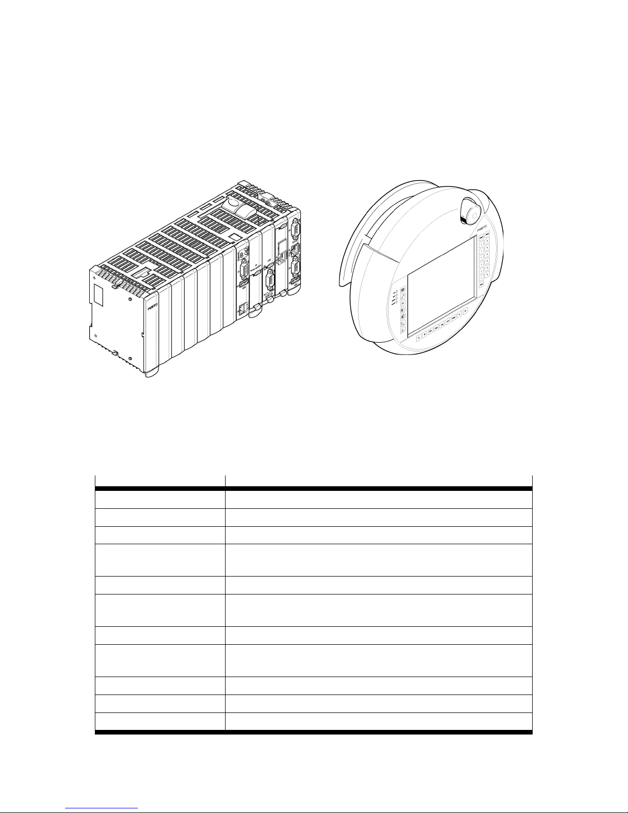
This document describes the “Festo CMXR-C2- multi-axis control system with robotic
technology functions” system with software version 1.0 and later. In addition to the actual
multi-axis control system, this system also includes the handheld terminal CDSA-D1-VX
and its emulation via software as a PC application.
CMXR-C2 multi-axis control system CDSA-D1-VX handheld terminal
1.1 Terminology used
Designation
Meaning
Central control unit
Basic unit of the CMXR multi-axis control system
Multi-axis control system
Central control unit with connected peripheral modules
Memory card
Compact Flash Card CF Type I
FTL
Festo Teach Language, movement-oriented programming language for the
CMXR multi-axis control system
TCP
Tool Center Point
DriveBus
Channel of communication between the CMXR multi-axis control system
and Festo motor controllers on a CANopen DS402 basis
Festo Configuration Tool (FCT)
Parameterisation and commissioning software for Festo drives
FCT PlugIn
Software module for a particular device in the Festo Configuration Tool
(FCT)
Handheld terminal
CDSA-D1-VX as commissioning and operator unit
CDSA emulation
Emulation of the functions of the handheld terminal on a PC
CoDeSys
Integrated PLC (process control)
Page 9
1. Introduction
Festo GDCP-CMXR-C2-SY-EN 1205b 9
1.2 Additional documents
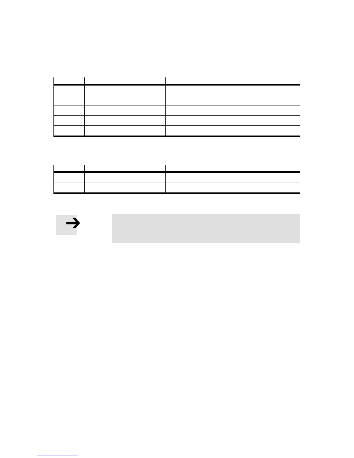
The total functionality of the multi-axis control system CMXR-C2 is described in the
following documents:
Part No.
Name
Contents
571688
GDCP−CMXR−C2−SY-EN
This system manual
571694
GDCP−CMXR−C2−HW−EN
Hardware description of the CMXR-C2
560316
GDCP−CMXR−SW-EN
Basis programming of the CMXR family
571706
GDCP−CMXR−C2-ST−EN
Special programming instructions for tracking
571700
GDCP−CMXR−C2−CS−EN
Programming under CoDeSys
The operator unit CDSA-D1-VX also has two documents available:
Part No.
Name
Contents
560334
GDCP-CDSA-SY-EN
System manual for operator unit CDSA
560340
GDCP-CDSA-SW-EN
CDSA software manual
Note
These documents are available in six languages: DE, EN, ES, FR, IT
and SV. See brief operating instructions GDSP−CMXR−C2−SY−ML.
Page 10

2. Safety instructions
10 Festo GDCP-CMXR-C2-SY-EN 1205b
2. Safety instructions
2.1 Using the documentation
This document is intended for users and programmers of multi-axis structures and robots
that work together with the Festo CMXR multi-axis control system. There is a training
induction programme for the operation and programming. Appropriate personnel training
is a requirement.
2.2 Recommended operating conditions
Warning
The Festo CMXR multi-axis control system is not designed for
safety-relevant control tasks (e.g.: emergency stop or monitoring of
reduced speeds).
The Festo CMXR multi-axis control system conforms to category B
of EN-13849-1 and is thus not adequate for the implementation of
safety functions for the protection of persons.
Additional external protective measures that ensure the safe
operating condition of the entire system even in the event of a
malfunction must be adopted for safety-related control tasks or for
the safety of personnel.
Festo accepts no liability for any damage resulting from non-compliance with the warning
instructions in these operating instructions.
Note
The safety instructions on the products (chapter 2.5) and the safety
instructions on this manual (chapter 2.6) must be read prior to
commissioning.
If the documentation is not clearly understood in this language, please inform the supplier.
Fault-free and reliable operation of the control system depends on proper and professional
transportation, storage, assembly and installation as well as on careful operation and
maintenance.
Page 11
2. Safety instructions
Festo GDCP-CMXR-C2-SY-EN 1205b 11
2.3 Qualified personnel
Note
Only trained and qualified personnel should be allowed to handle
the electrical systems.
2.4 Safety instructions for this manual
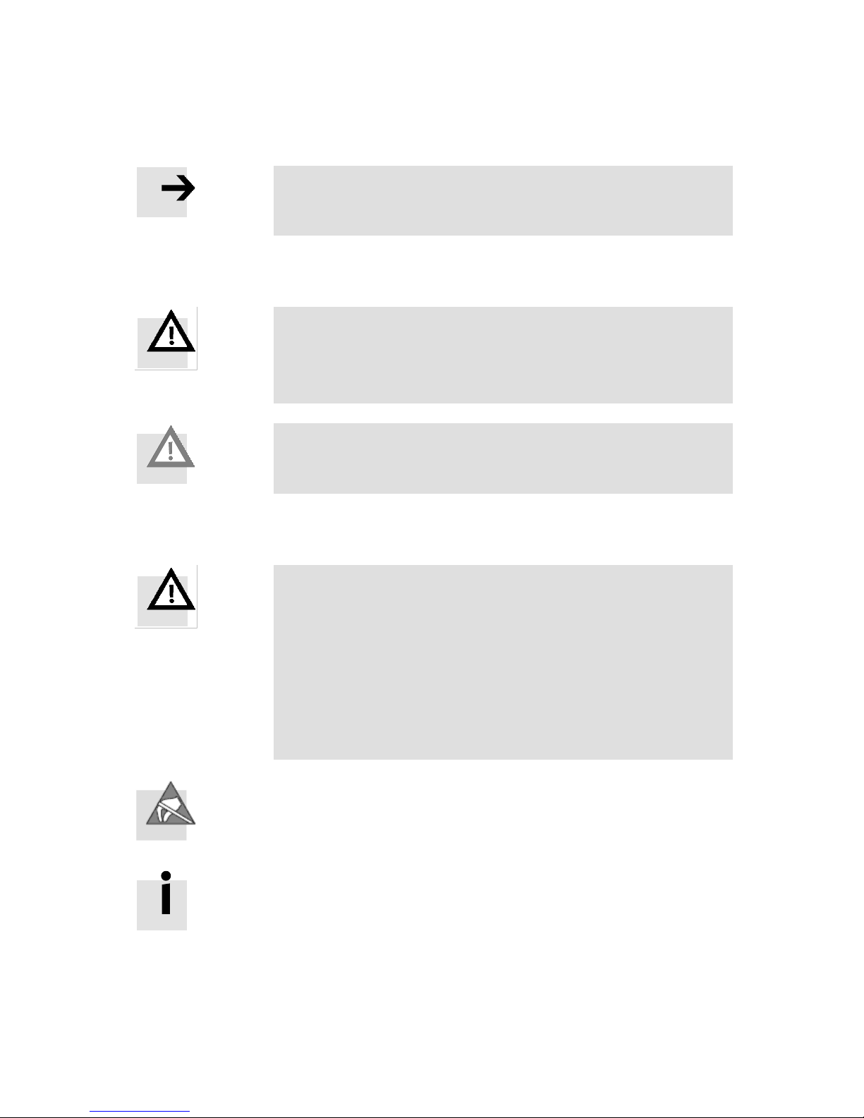
Warning
DANGER!
Considerable material damage and personal injury can occur if
these instructions are not observed.
Caution
Failure to comply can result in severe material damage.
2.5 Safety instructions for the products
Warning
DANGER!
The applicable regulations on special waste must be observed
when disposing of the batteries.
Although batteries have a low voltage, they can give off enough
current in a short circuit to cause combustible materials to ignite.
They must not, therefore, be disposed of together with conductive
materials (such as metal chips, wire wool contaminated with oil,
etc.).
Electrostatically sensitive devices: Incorrect handling can result in
damage to components.
Information
Instructions for EMC-approved installations can be found in the
product manual.
Page 12

2. Safety instructions
12 Festo GDCP-CMXR-C2-SY-EN 1205b
Warning
DANGER!
Dangerous movements!
Danger of death, serious bodily injury or material damage due to
unintentional movement of the axes!
2.6 Safety instructions for the product
Warning
DANGER!
Danger of death due to insufficient EMERGENCY STOP devices!
Emergency stop devices must remain operational and accessible in
all operating modes of the system. Unlocking the EMERGENCY
STOP device must not cause an uncontrolled restart of the system!
First check the EMERGENCY STOP chain, then switch on!
Warning
DANGER!
Danger to personnel and equipment!
Test every new program before commissioning the system!
Warning
DANGER!
Retrofittings and modifications may impair the safety of the system!
The consequences of this could be personal injury, material
damage or damage to the environment. Possible retrofittings or
modifications to the system with component parts from external
manufacturers must therefore be approved by Festo.
Page 13

2. Safety instructions
Festo GDCP-CMXR-C2-SY-EN 1205b 13
Warning
DANGER!
Dangerous voltage!
Unless otherwise specified, maintenance work must always be
carried out with the system switched off! At the same time, the
system must be protected against being restarted again by
unauthorised persons or unintentionally.
Any measuring or test work required on the system must be carried
out by expert electrical technicians.
Caution
Only spare parts approved by Festo may be used.
Page 14
3. Modular multi-axis control system CMXR-C2
14 Festo GDCP-CMXR-C2-SY-EN 1205b
3. Modular multi-axis control system CMXR-C2
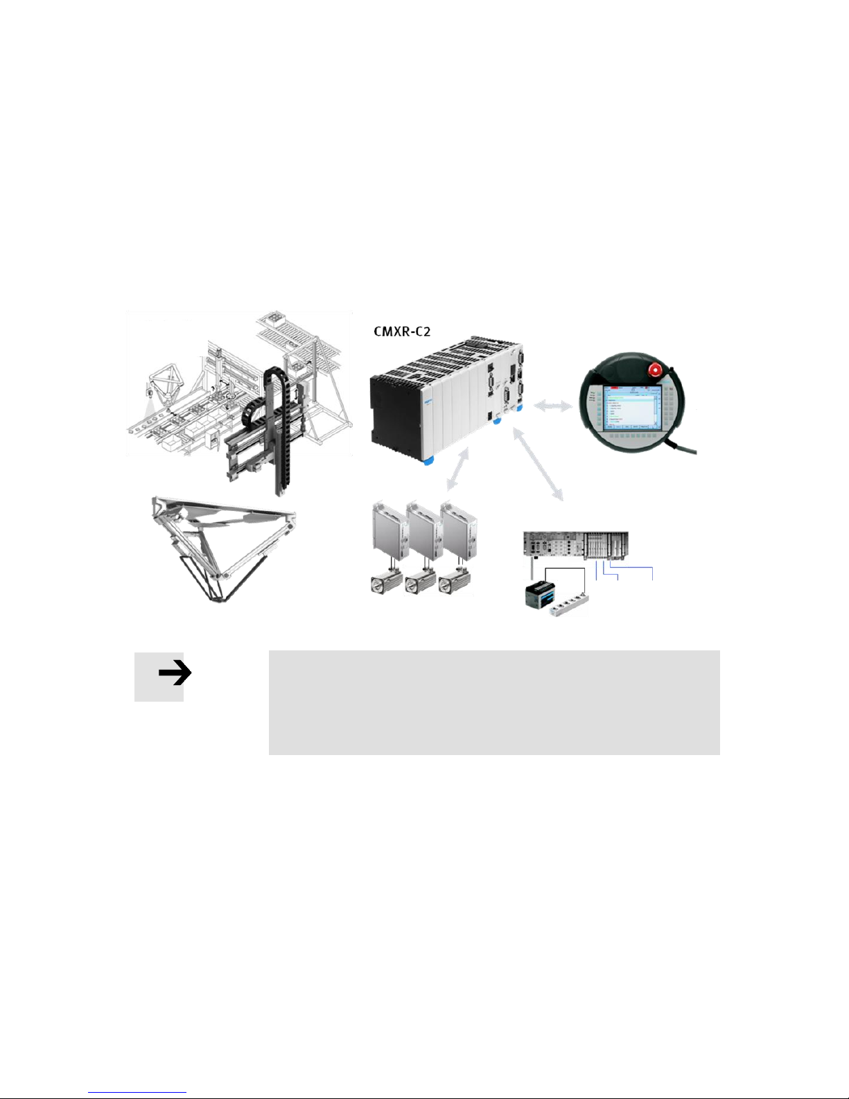
The multi-axis control system CMXR-C2 is a modular control system composed of a central
control unit CMXR-C2 with various communication interfaces, input/output modules and a
handheld terminal. The multi-axis control system is used for activating kinematics from
the Festo Modular System for Handling and Assembly Technology, additional axes and
peripheral equipment. Programming is done in the language FTL (Festo Teach Language).
The multi-axis control system CMXR-C2 is especially suitable for tracking problems; for
parts detection, vision sensors (camera ...) can be connected.
Note
All the examples and applications used in this manual are nonbinding and do not lay claim to be correct and complete. All the
necessary regulations must be observed when using the CMXR
multi-axis control system.
Mechanics +
vision
Handheld terminal
Electrical drive technology
Valve terminals, remote I/O
Grippers,
drives
Page 15
3. Modular multi-axis control system CMXR-C2
Festo GDCP-CMXR-C2-SY-EN 1205b 15
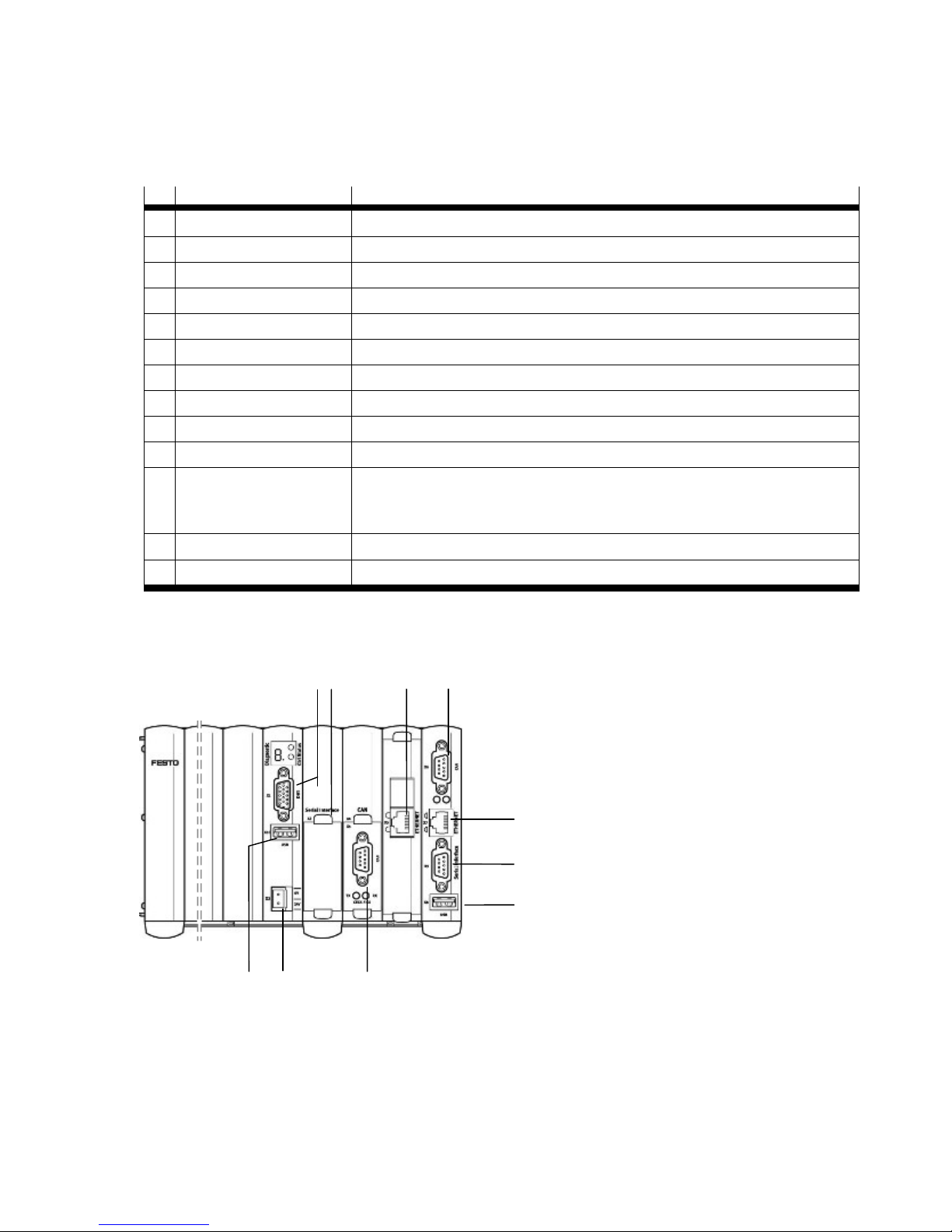
3.1 Central control unit CMXR-C2
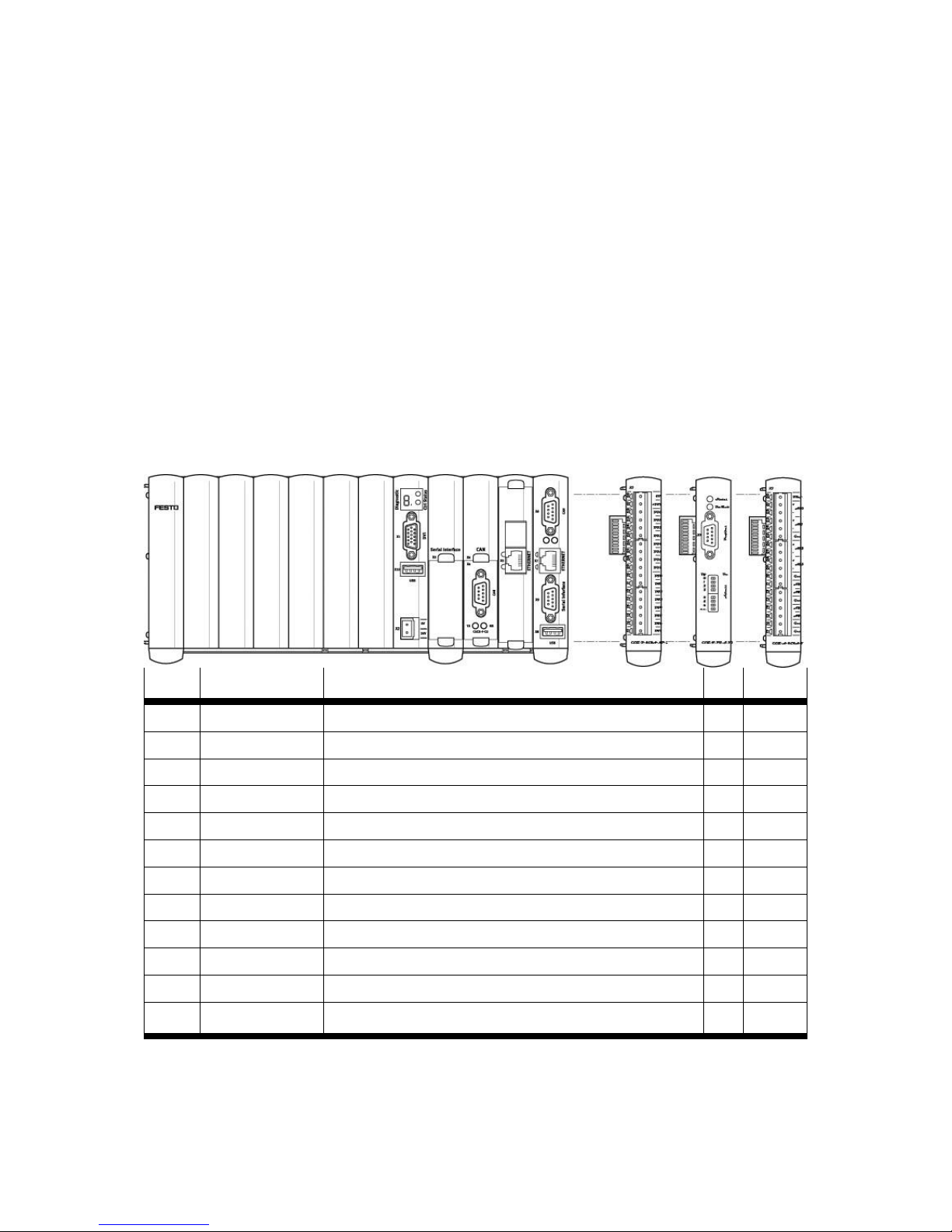
Scope of delivery:
No.
Designation
Significance
-
Central control unit
CPU and housing for H-rail mounting in the control cabinet
-
CF memory card
CompactFlash memory card CF Type I, size 256 MB
-
7-segment display
Information on diagnostics
1
X1 DVI interface
Currently not used
2
X2 power supply
Power supply 24 V DC
3
X3 slot
Free slot for optional serial interface
4
X4 CAN, peripherals
Connection of peripheral devices under CoDeSys, e.g. valve terminal
5
X5 Ethernet
Local interface (without gateway), preferably for commissioning
6
X6 CAN, DriveBus
Interface to the motor controllers of the kinematics
7
X7 Ethernet
General interface with gateway; for network and commissioning
8
X8 USB interface
USB port for saving and restoring programmes as well as for removing diagnostic
information for servicing purposes. Further information can be found in the CDSA
software manual.
9
X9 serial interface
Serial interface for use under CoDeSys
aJ
X10 USB interface
Reserved for later extensions.
Table 3.1 Scope of delivery CMXR-C2
Fig. 3.1 Components on the front of the CMXR-C2
Page 16
3. Modular multi-axis control system CMXR-C2
16 Festo GDCP-CMXR-C2-SY-EN 1205b
3.2 Memory card
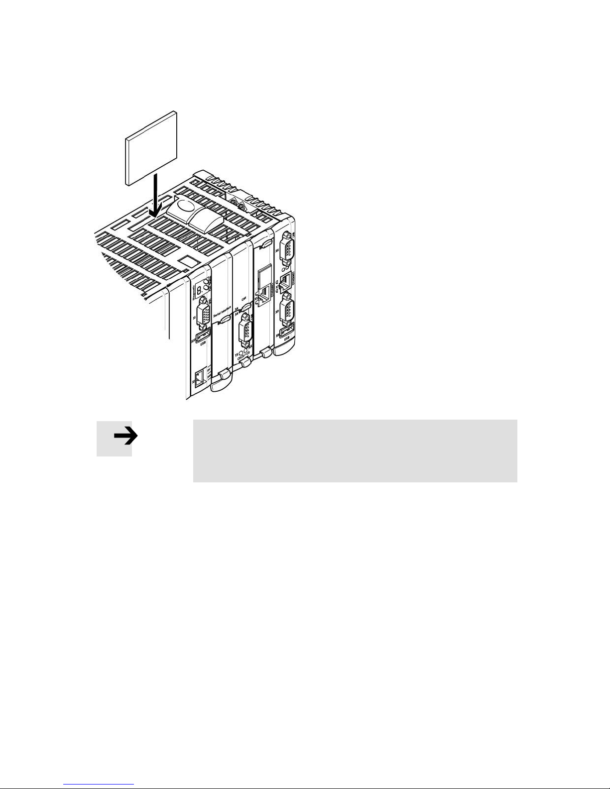
The data for the CMXR-C2 are saved on a
memory card. This includes all data required
for the operation, such as the operating
system, configuration data and movement
programs.
The memory card is inserted into the
associated slot. Pulling and inserting the
card is not permitted during the operation.
Note
To eject or insert the memory card, always make sure the central
control unit is disconnected from the power supply. Ejecting or
inserting is not allowed if the control unit is still live.
The type of the memory card can be found in the hardware description of the central
control unit.
To produce backup copies, the memory card can be very easily copied. This can be done
via a PC using a punch card reader or via Festo Configuration Tool (FCT).
Should the CMXR hardware or the memory card become defective, the defective part can
be easily exchanged. Additional software or a PC is not required.
Page 17
3. Modular multi-axis control system CMXR-C2
Festo GDCP-CMXR-C2-SY-EN 1205b 17
Caution
The memory card is a storage location for all the multi-axis control
system's data. Using this data carrier for other purposes is impermissible. Otherwise, the operability of the storage medium may be
impaired.
3.2.1 File system
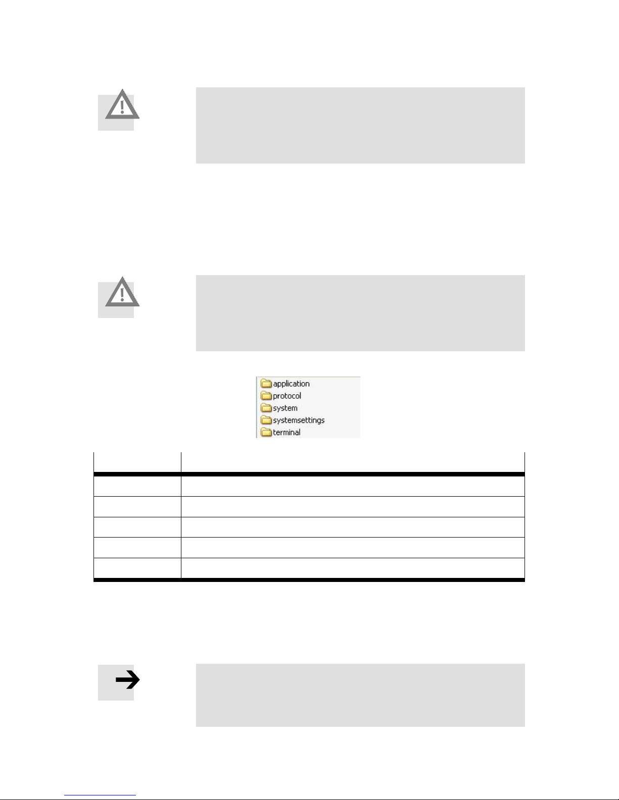
The memory card has a directory structure in which required data, such as configuration,
program and system data, can be stored. These directories are created during the installation of the multi-axis control system and must not be changed or added to. Otherwise,
the operability of the system is no longer guaranteed.
Caution
The required directory structure is created during the installation of
the multi-axis control system. It must not neither be changed nor
added to. Any type of manipulation here results in the operability
not being guaranteed.
Illustration of the directory structure on the memory card:
Directory name
Meaning
application
File for all user data such as configuration, programs and program data
protocol
File for report files
encoder
System directory
systemsettings
System directory
Terminal
System directory
Table 3.2 File directories on the memory card
All the required data for the application are stored in the “application” directory. This
applies to the configuration of the CMXR multi-axis control system as well as all FTL
projects and programs in the application.
Note
With the aid of the Festo Configuration Tool (FCT) all system data,
the configuration and the FTL programs required for the operation
are generated and stored on the memory card.
Page 18
3. Modular multi-axis control system CMXR-C2
18 Festo GDCP-CMXR-C2-SY-EN 1205b
3.2.2 Application directory
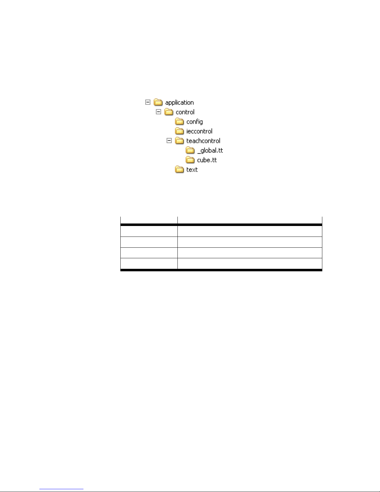
All configuration data, FTL project data and program data are stored in the
“application\control” directory.
Illustration of the directory structure for the application directory:
The application directory includes a “control” directory. This is divided into the following
directories:
Directory name
Meaning
config
Target directory of the application configuration
ieccontrol
Data for CoDeSys
teachcontrol
Contains all FTL projects
text
Contains any message texts in the application
Table 3.3 Application directory
The “teachcontrol” directory contains all FTL projects which are each represented by a
directory. All FTL programs assigned to the project are located in this project directory. In
the above directory tree, the projects “_global” and “cube” are created.
3.3 CAN interfaces X4/ X6
The CAN X6 interface of the CMXR-C2 is reserved for the communication with the motor
controllers of the kinematics via DriveBus. A different use is not possible.
Other typical process peripheral equipment, such as Festo valve terminals or I/O modules,
can be connected via interface CAN X4. The devices must support CANopen DS 301.
Configuration and programming are done via CoDeSys.
Page 19
3. Modular multi-axis control system CMXR-C2
Festo GDCP-CMXR-C2-SY-EN 1205b 19
3.4 Ethernet interfaces X5/ X7
The multi-axis control system CMXR-C2 has two Ethernet interfaces with RJ45.
- X5 without gateway for local networks
- X7 with gateway for higher-level networks
Note
The use of an Ethernet switch is recommended for minimising the
load for the Ethernet network.
Note
The CMXR-C2 multi-axis control system is not DHCP-capable.
Caution
X5 and X7 may not be located in the same network
3.4.1 IP address on delivery
The CMXR multi-axis control system has, on delivery, a minimal installation on the memory
card so that the network connection can be established after connection to the power
supply. The network settings are pre-assigned as follows:
- X5 deactivated
- X7 activated
Network parameter X7
Value
IP address
192.168.100.100
Subnet mask
255.255.255.0
Gateway address
0.0.0.0
Table 3.4: Preset network parameters X7
To establish a connection to the CMXR multi-axis control system, the corresponding
network settings have to be undertaken on the PC.
3.5 USB interfaces X8/ X10
The CMXR-C2 has 2 USB interfaces:
The USB port X8 for saving and restoring programmes as well as for removing
diagnostic information if servicing is required. Further information can be found in
the CDSA software manual.
The USB port X10. It is reserved and cannot be used.
Page 20
3. Modular multi-axis control system CMXR-C2
20 Festo GDCP-CMXR-C2-SY-EN 1205b
3.6 Serial interfaces X3/ X9
The CMXR-C2 permits operation of two serial interfaces. Configuration and use of the
interfaces takes place under CoDeSys. The option slot X3 is not equipped on delivery and
serves to extend the CMXR-C2 control system with an additional serial interface.
3.7 Peripheral modules
The modular multi-axis control system can be expanded with peripheral modules from the
CECX series.
3.7.1 Extension modules
The extension modules are attached on the right side of the central control unit. The
modules are connected through the system bus by means of a pin contact. The location of
an extension module is freely selectable. Since each module has its own address, it can be
uniquely identified. A maximum of 12 peripheral modules can be connected to the multiaxis control system CMXR-C2.
Part No.
Designation
Meaning
FTL
CoDeSys
552096
CECX-D-16E
Digital input module with 16 inputs
x x 552097
CECX-D-14A-2
Digital output module with 14 outputs
x x 552099
CECX-D-8E8A-NP-2
Digital mixed module with eight inputs and eight outputs
x x 552100
CECX-A-4E4A-V
Analogue module with four inputs, four outputs for voltage
x x 552101
CECX-A-4E4A-A
Analogue module with four inputs, four outputs for current
x x 552117
CECX-C-2G2
Encoder module with two inputs
x x 553972
CECX-D-6E8A-PN-2
Digital I/O module in NPN technology
x
x
553973
CECX-E-4E-T-P1
Temperature measurement module,
x
x
553974
CECX-E-6E-T-P2
Temperature measurement module,
x 553979
CECX-S-S4
Optional module RS485/422
x 553981
CECX-F-PB-V1
PROFIBUS Master V1
x
565598
CECX-F-PB-S-V1
PROFIBUS slave V1
Table 3.5 Peripheral modules system CMXR-C2
Page 21
3. Modular multi-axis control system CMXR-C2
Festo GDCP-CMXR-C2-SY-EN 1205b 21
Note
The maximum possible 12 modules can be a mixture of the named
peripheral modules. The PROFIBUS modules are an exception: they
can be used only once in the system.
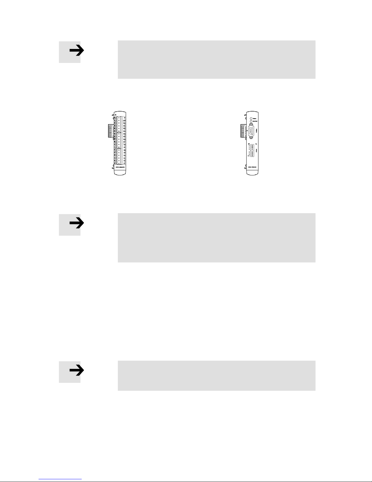
Examples for extension modules:
CDCX-D-8E8A-NP-2
CECX-F-PB-S-V1
Digital mixed module with eight inputs and eight
outputs
PROFIBUS slave module DPV1
Note
The planning of the modules is managed by Festo Configuration
Tool (FCT).
Please refer to the CMXR programming manual for the application
of the modules in FTL programs.
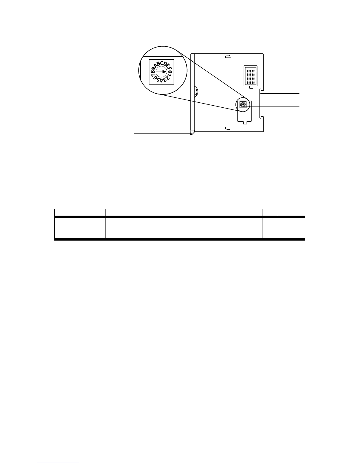
3.7.2 Addressing of the extension modules
Each peripheral module has an address switch that is located underneath a cover. It is
designed as a rotary switch. You can use an appropriate tool to set the module address on
the address switch.
The following applies:
- Each address may only be used once inside a module type.
- The same addresses are allowed in different modules.
Note
The PROFIBUS modules do not have an address switch, since they
may be installed in the system only once.
Page 22
3. Modular multi-axis control system CMXR-C2
22 Festo GDCP-CMXR-C2-SY-EN 1205b
1 Bus plug
(behind cover)
2 Recess for H-rail
3 Address switch
(module address)
4 H-rail locking
lever
3.7.3 Card modules
The CMXR-C2 central control unit has 3 slots for card modules. Of these, X4 and X5 are
equipped on delivery and by definition belong permanently to the actual central control
unit.
The slot X3 is reserved for expansion with a serial interface.
Designation
Significance
FTL
CoDeSys
CECX-F-CO
Option module CAN at X4
x CECX-S-S4
Option module RS485/422 an X3
x
3.7.4 Front panel plug
Standard plugs with a grid dimension of 5.08 mm are needed for the power supply and for
connecting the digital and analogue signal cables. Encoder signals are connected via a
SUB-D plug, the fieldbuses CAN and PROFIBUS via suitably approved fieldbus plugs.
The following tables include the required plug combinations and a recommended selection
of plugs. The number of pins can be selected differently, as desired.
4 1 2
3
Page 23
3. Modular multi-axis control system CMXR-C2
Festo GDCP-CMXR-C2-SY-EN 1205b 23
Peripheral module
Plug type
No. of
CMXR-C2
2-pin for power supply
9-pin SUB-D (bush) for each CAN bus
RJ45 plug connector for Ethernet
1
1 … 2
1 … 2
CECX-D-16E
CECX-D-8E8A-NP-2
CECX-D-6E8A-PN-2
CECX-A-4E4A-V
CECX-A-4E4A-A
CECX-E-4E-T-P1
2-pin for power supply
8-pin for signals
1
2
CECX-D-14A-2
2-pin for power supply
8-pin for signals
6-pin for signals
2
1
1
CECX-E-6E-T-P2
6-pin for signals
2
CECX-C-2G2
2-pin for power supply
2-pin for latch signals
SUB-D 9-pin (bush) for encoder
1
1
2
CECX-F-PB-V1
PROFIBUS plug connector SUB-D
(plug connector)
1
CECX-F-PB-S-V1
PROFIBUS plug connector SUB-D
(plug connector)
1
Table 3.6 Plugs for peripheral modules on the CMXR-C2
Note
It is recommended you use 2-pin plugs for connecting up the power
supply with the peripheral modules. Should signal cables have to
be disconnected for commissioning, then the power supply for the
modules is maintained.
An overview of available plug connectors can be found at http://www.festo.com/katalog.
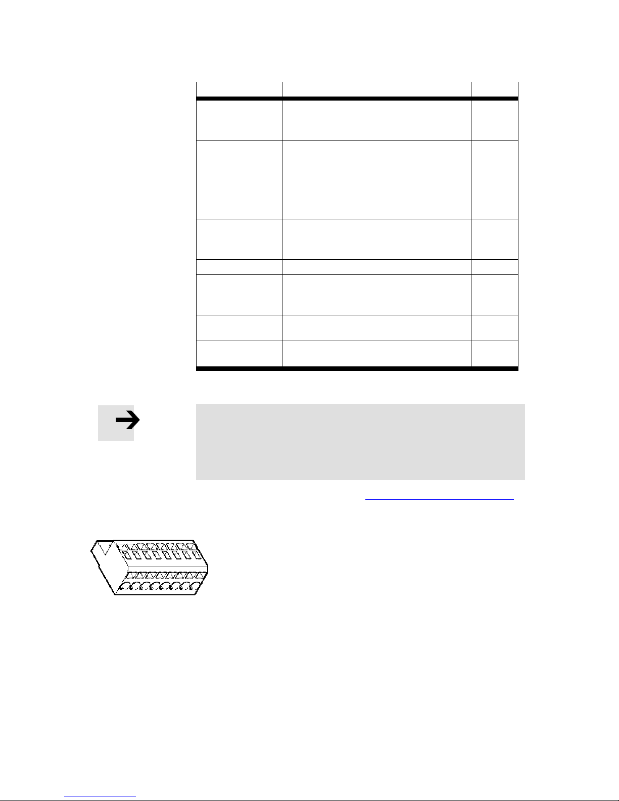
Illustration of 8-pin plug NECC-L1G8-C1 with spring-loaded terminal
Page 24
4. Configuration using FCT
24 Festo GDCP-CMXR-C2-SY-EN 1205b
4. Configuration using FCT
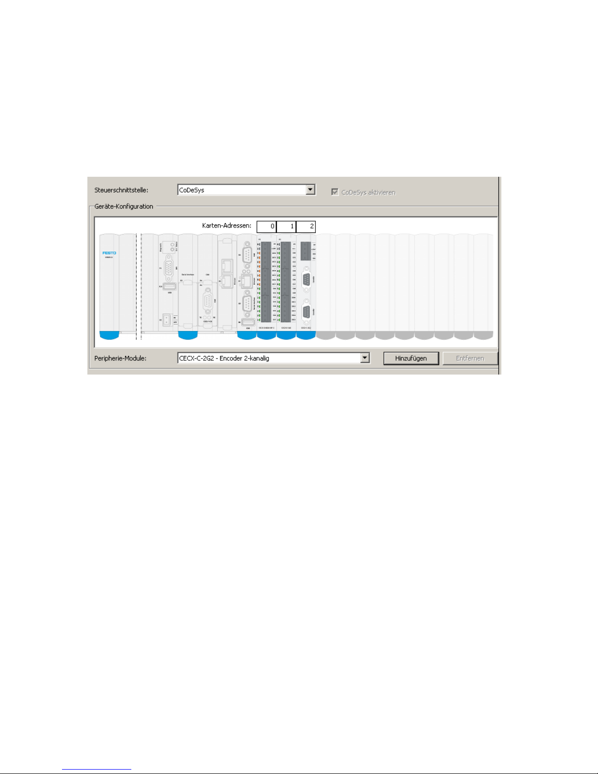
The configuration of the multi-axis control system CMXR-C2 is carried out via the Festo
Configuration Tool (FCT). This software has graphically supported dialogue pages for the
guided input of the required data.
Example of a graphical configuration page:
The Festo Configuration Tool (FCT) is used to deal with the configuration of the
- Central control unit CMXR-C2,
- Peripheral signals,
- Control interface,
- Selection of the kinematics,
- Data for axis dynamics
for example. Please refer to the CMXR PlugIn documentation in Festo Configuration Tool
(FCT) for more information.
Page 25
5. Festo Teach Language (FTL)
Festo GDCP-CMXR-C2-SY-EN 1205b 25
5. Festo Teach Language (FTL)
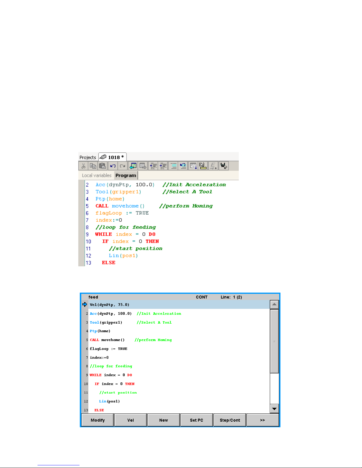
The movement programs for the multi-axis control system CMXR are written using the textbased programming language FTL (Festo Teach Language). FTL provides a high-performance store of commands, e.g. for movements, dynamics, branchings, loops and the
integration of peripheral signals. In the CMXR multi-axis control system the FTL program is
processed by an interpreter.
The FTL programs can be programmed offline and online. The FTL Editor is available in the
Festo Configuration Tool (FCT) for offline programming. Online programming is carried out
via the CDSA-D1-VX mobile handheld terminal.
Please refer to the CMXR programming manual for more information.
Example of an FLT program – shown in the FCT plug-in
Example of an FLT program – shown on the operator unit CDSA-D1-VX:
Page 26

5. Festo Teach Language (FTL)
26 Festo GDCP-CMXR-C2-SY-EN 1205b
5.1 Program processing
An FTL program is processed in the CMXR multi-axis control system by an interpreter. This
allows making very quick changes to the program, which take immediate effect.
The FTL programmes are not processed by the memory card, but rather from the CMXR's
internal memory.
Note
The maximum number of positions in a project is limited by the
storage capacity of the central control unit. Exceeding the storage
capacity is reported as an error.
Limit of CMXR-C1: approx. 1,500 positions
Limit of CMXR-C2: approx. 10,000 positions
5.1.1 Downloading FTL programs
FTL programs are normally written via the CMXR plug-in in the Festo Configuration Tool
(FCT) and then transferred to the CMXR memory card per download.
The memory card can also be connected to the PC via Ethernet and by using the IP address
of the CMXR central control unit. Programme This connection can also be used to store FTL
programmes on the memory card.
If a project that is already loaded on the memory of the CMXR control system is copied
onto the memory card, then this project will not be updated. To load the new project from
the memory card onto the CMXR control system's memory, the active project must be
closed (it will be unloaded) and then loaded again. This procedure can be carried out via
the project mask in the handheld terminal or via CoDeSys.
Note
An active, loaded project is not updated in the CMXR control
system's RAM by downloading it to the memory card. The project
must be unloaded and then loaded again to update the data.
Page 27
6. CDSA-D1-VX handheld terminal
Festo GDCP-CMXR-C2-SY-EN 1205b 27
6. CDSA-D1-VX handheld terminal
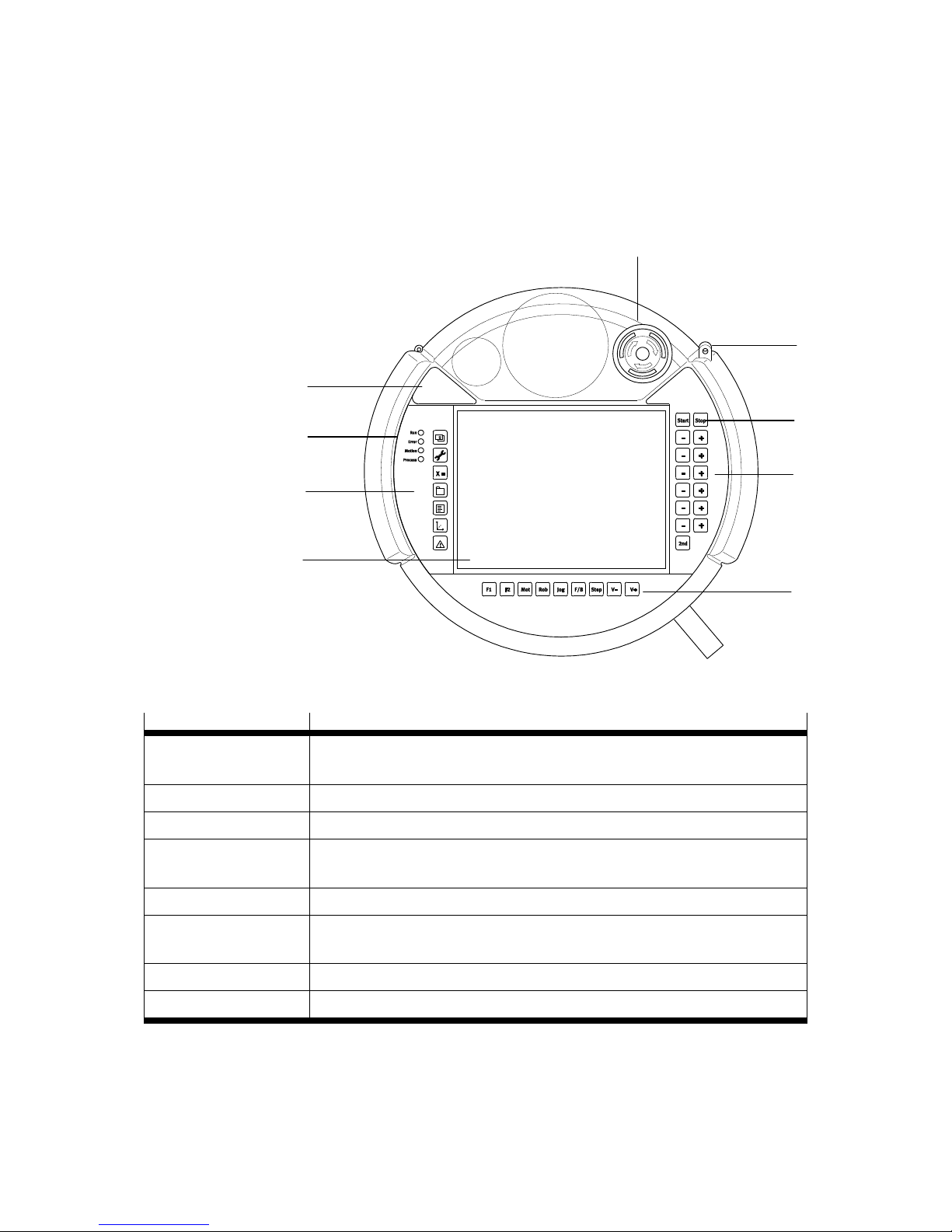
All operations required for operation - even the correction of FTL programs - can be run
using the mobile handheld terminal CDSA. A largely functionally equivalent CDSA
emulation on a PC is also available.
The following illustration shows the CDSA handheld terminal from the front side:
1 EMERGENCYSTOP
2 Touch pin
3 Start and stop
buttons
4 Buttons for jog
mode
5 Buttons for
selecting functions
6 Coloured touch
screen
7 Buttons for
selecting functions
8 Display LEDs
9 Cover for USB
interface
Fig. 6.1 Handheld terminal CDSA
Function
Description
EMERGENCY STOP
button
2-channel EMERGENCY STOP button acc. to category 3, for integration in the
customer-specific EMERGENCY STOP circuit
Start and stop buttons
For starting and stopping the movement program
Buttons for jog mode
Buttons for moving the axes in different coordinate systems
Buttons for selecting the
functions
Buttons for selecting the various functions, such as coordinate systems,
position display, programming
Display LEDs
Display of states, e.g. errors
Touch screen
6.5” TFT colour display with touch screen, which can be operated by finger or
touch pin
Touch pin
Pin for operating the touch screen
USB interface X8
On the import and export of FTL programs and saving status reports
Table 6.1 Functions of the CDSA handheld terminal, front
1 2 4 6 3 7 5
8
9
Page 28
6. CDSA-D1-VX handheld terminal
28 Festo GDCP-CMXR-C2-SY-EN 1205b
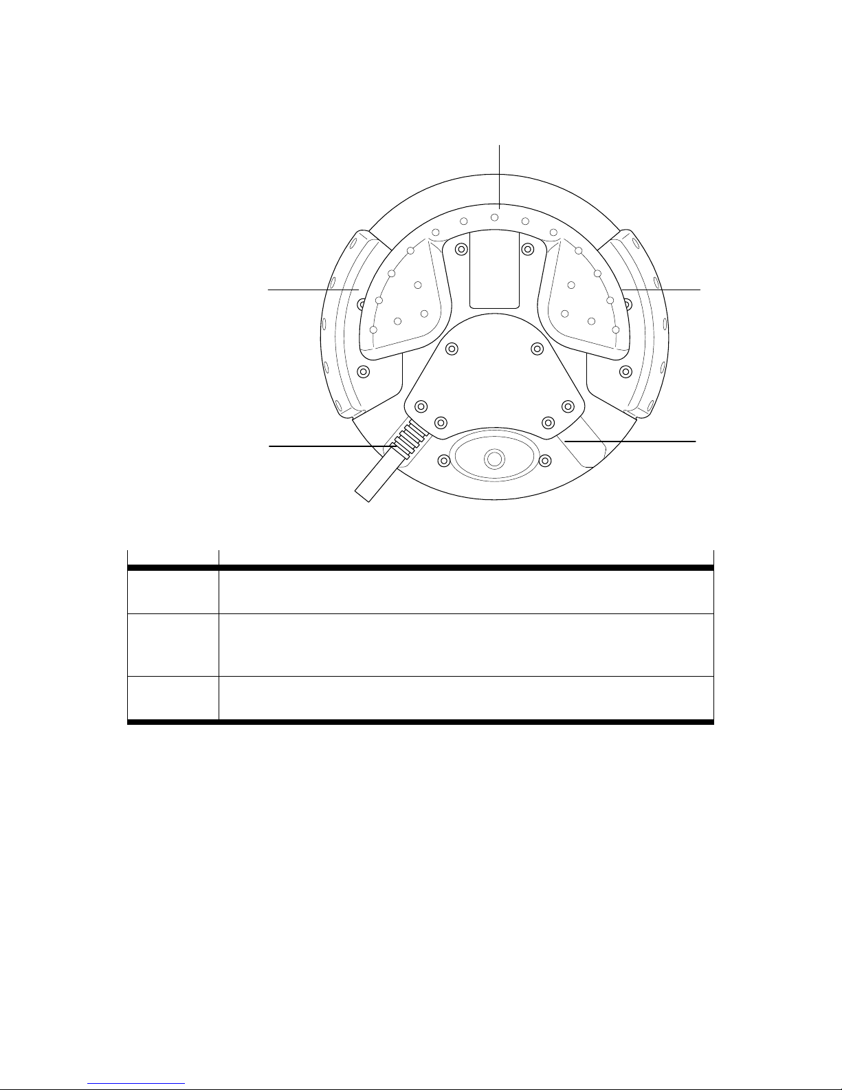
The following illustration shows the CDSA handheld terminal from the rear side:
1 Handle for rightand left-handed
people
2 Permission
button
3 Cable outlet
Fig. 6.2 CDSA handheld terminal - rear side
Function
Designation
Handle
The handheld terminal has an ergonomic handle that can also be used as a hand rest and
is suitable for right- and left-handed people.
Permission
button
The handle has a 3-stage, 2-channel permission button built in on both the right- and lefthand side (for right- or left-handed people) and prepared for the customer-specific safety
circuit.
Cable outlet
The cable outlet can be defined as being on the right or left depending on the installation
of the cable.
Table 6.2 Functions of the handheld terminal, rear side
The ergonomic design of the handheld terminal also allows operation while lying down,
e.g. on a table. The arrangement of the housing and handle also makes sure the terminal is
in a secure standing position.
1 3 2 3 2
Page 29
6. CDSA-D1-VX handheld terminal
Festo GDCP-CMXR-C2-SY-EN 1205b 29
6.1 Installation
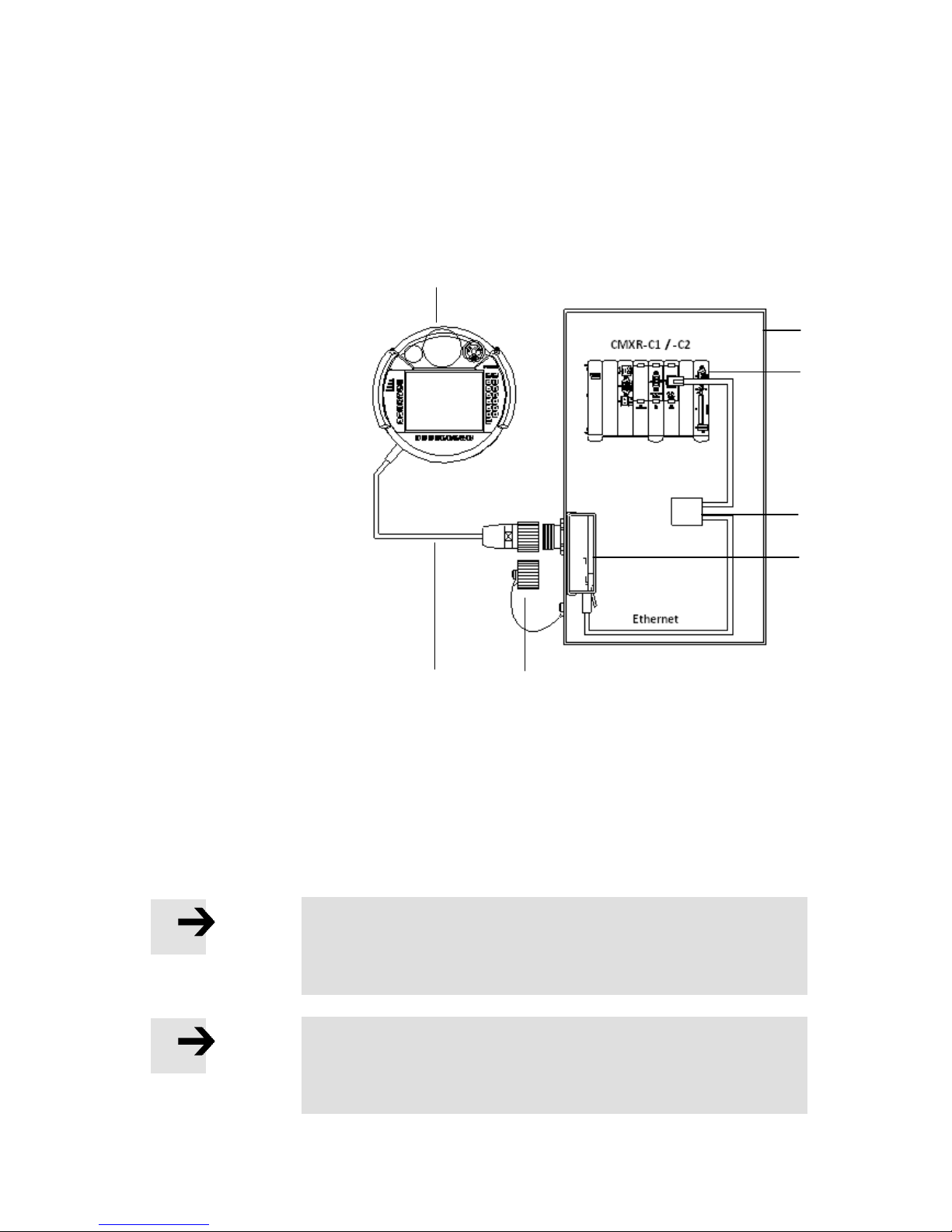
The handheld terminal communicates with the CMXR multi-axis control system via an
Ethernet connection. The interface for both communication partners is formed by an
interface unit that has connections for the handheld terminal and the CMXR multi-axis
control system.
Overview diagram of handheld terminal's installation:
1 Control cabinet
2 Multi-axis control
system CMXR-C1/-C2
3 Ethernet cable
(crossover) / Ethernet
cable with switch
4 CAMI-C interface unit
with …
2-channel EMERGENCYSTOP
2-channel permission
button
24V supply
5 CAMF-B bridge
connector
6 NESC-C-D1-x-C1 cable
7 CDSA handheld terminal
Fig. 6.3 Installation of CDSA handheld terminal
The interface unit is normally installed in the control cabinet. A cut-out is used to secure
the terminal socket for the interface unit against turning and allows the unit to be guided
through to the outside. A lock nut is used to fix down the interface unit.
Note
We recommend an intelligent switch is used for the Ethernet
connection. This is the only way a PC (with FCT software) and an
operator unit can be connected up simultaneously.
Note
Please refer to the relevant manuals for more information on the
installation. Due to the application involved, the required safety
regulations must also be observed.
1 2 3
6 4 5
7
Page 30
6. CDSA-D1-VX handheld terminal
30 Festo GDCP-CMXR-C2-SY-EN 1205b
6.2 CAMI-C interface unit
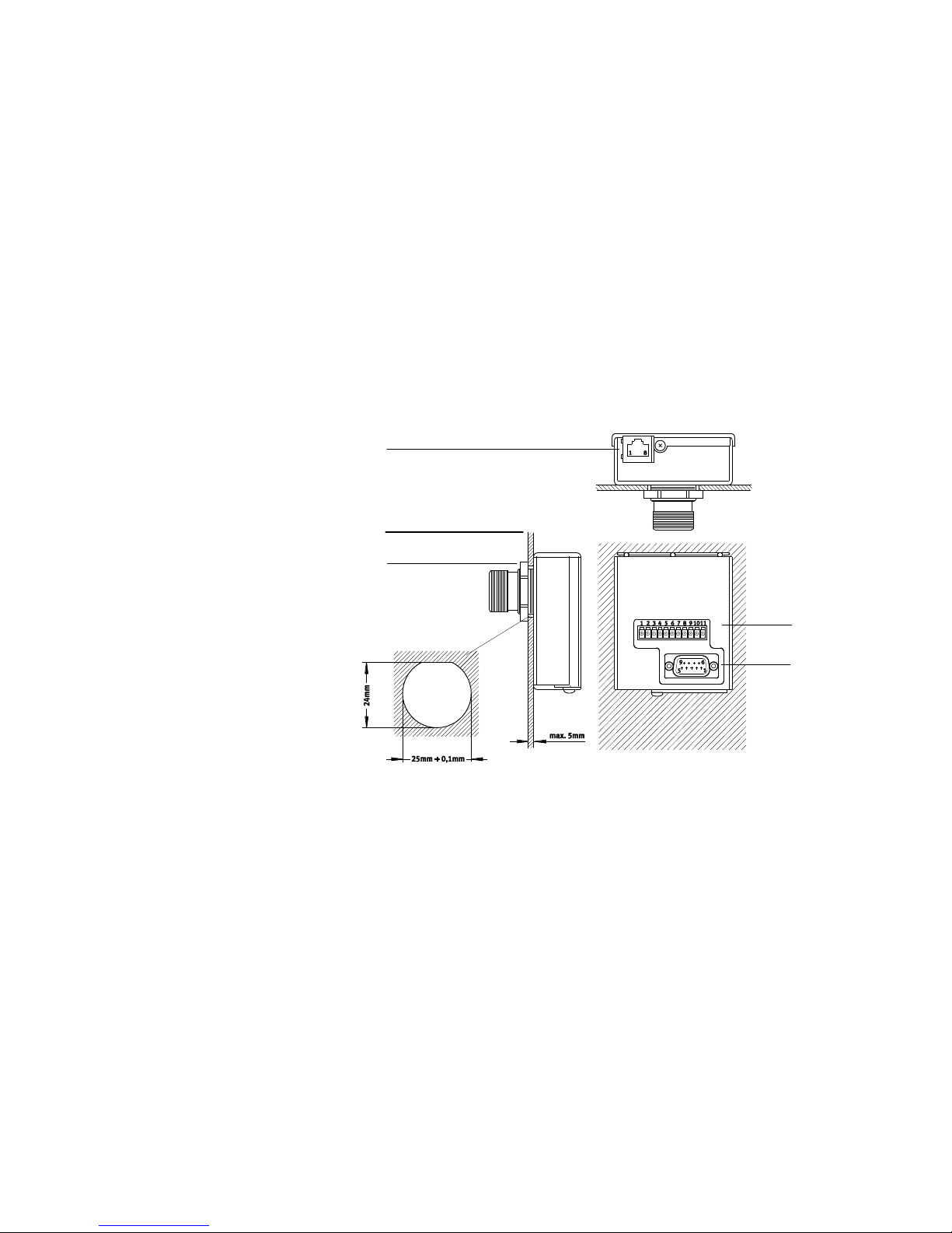
The handheld terminal is connected up to the CMXR multi-axis control system via an
interface unit. The interface unit has the following connections:
- Ethernet connection, communication between CMXR and handheld terminal
- 11-pin connector for
- 24V DC power supply for the handheld terminal
- 2-channel connection for EMERGENCY-STOP switch
- 2-channel connection for permission buttons
1 Connector for
supply,
EMERGENCY-STOP
and permission
button signals
2 9-pin SUB-D
plug, not in use
3 Connecting
thread for handheld
terminal cable
4 Retaining nut
5 Control cabinet
panel
6 Ethernet
connection
Fig. 6.4 CAMI-C interface unit
The illustration shows the CAMI-C interface unit installed on an outside panel of the control
cabinet. Please observe that the cut-out must be made using a suitable tool.
6.3 Disconnecting the handheld terminal
It is possible to control the CMXR multi-axis control system via an external control system,
i.e. to specify instructions such as start or stop externally. The handheld terminal is not
absolutely necessary for such operations. The handheld terminal can be disconnected if
the commissioning work is concluded.
If a handheld terminal is disconnected at the interface unit during operation, then the
EMERGENCY STOP circuit is opened. There is now an EMERGENCY-STOP situation that
cannot be acknowledged due to the open EMERGENCY STOP circuit. To be able to continue
working despite a disconnected handheld terminal (control could come from an external
control system), the bridge connector (named CAMF-B-M25-G4) is screwed into the
interface unit instead of the handheld terminal.
6 5 1
2
4
Page 31
6. CDSA-D1-VX handheld terminal
Festo GDCP-CMXR-C2-SY-EN 1205b 31
The bridge connector has two internal bridges for the 2-channel EMERGENCY-STOP signal.
These two bridges close the EMERGENCY-STOP circuit and the EMERGENCY-STOP situation
can be acknowledged.
Note
A solution which allows the handheld terminal to be disconnected
without interrupting the EMERGENCY-STOP circuit is not planned.
This would require taking the whole installation into consideration
and with it the applicable safety regulations. If this is required, then
the customer has to find a special solution parallel to the required
safety regulations.
Caution
The EMERGENCY-STOP button for a disconnected handheld terminal
is not active. The operator is under obligation to clear up the disconnected handheld terminals such that inadvertent actuation of
the inactive EMERGENCY-STOP button is not possible.
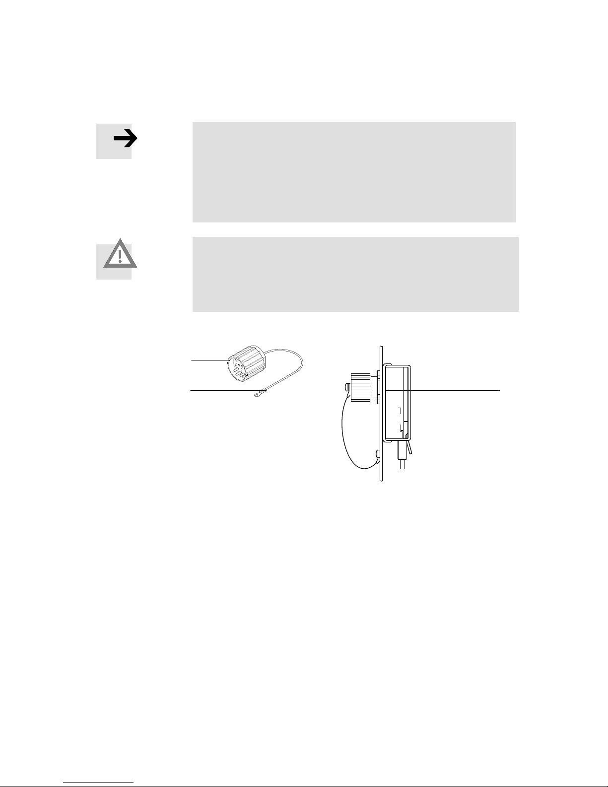
1 Bridge connector
screwed onto
interface unit
2 Wire cable with
eyelet for fixing
3 Bridge connector
Fig. 6.5 CAMF-B-M25-G4 bridge connector
1 2 3
Page 32
6. CDSA-D1-VX handheld terminal
32 Festo GDCP-CMXR-C2-SY-EN 1205b
6.4 Hardware overview
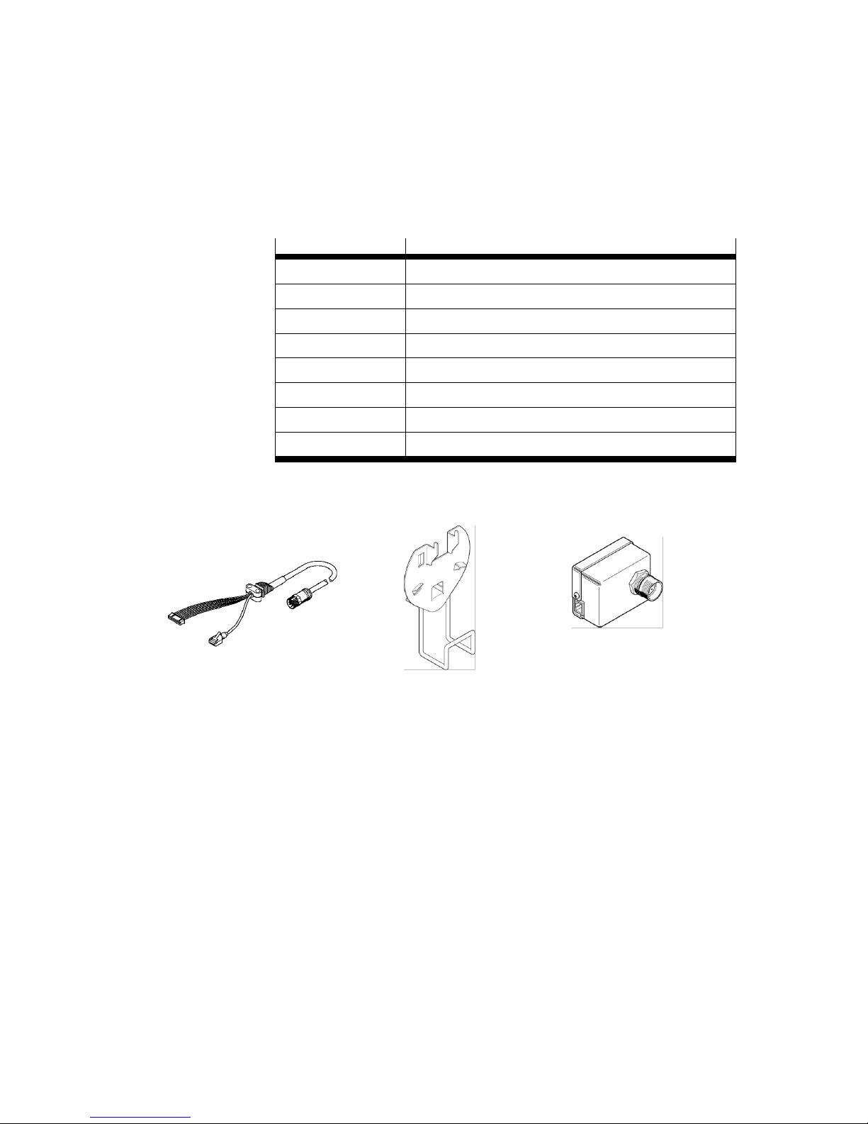
Three prefabricated cables are available at various lengths for connecting the handheld
terminal to the interface unit. Also available is the bridge connector for bridging the
EMERGENCY-STOP signals in the disconnected status, as well as a wall bracket with
a cable holder for setting down the handheld terminal.
Type
Meaning
CDSA-D1-VX
Handheld terminal
NESC-C-D1-5-C1
Prefabricated connecting cable, length 5 m
NESC-C-D1-10-C1
Prefabricated connecting cable, length 10 m
NESC-C-D1-15-C1
Prefabricated connecting cable, length 15 m
CAMI-C
Interface unit
NECC-L1G11-C1
11-pin plug for interface unit
CAMF-B-M25-G4
Bridge connector for interface unit
CAFM-D1-W
Wall bracket with holder for cable
Table 6.3 Handheld terminal's hardware overview
6.5 Software
The handheld terminal has a graphical user interface that has an easy-to-understand and
intuitive design. Specialist programming or computer knowledge is not required to learn
how the handheld terminal is handled. All information is available in German and English.
The language is selected within the software for the handheld terminal, without having to
restart the system.
Prefabricated connecting cable
NESC-C-D1-xx-C1
Wall bracket CAFM-D1-W
CAMI-C interface unit
Page 33
6. CDSA-D1-VX handheld terminal
Festo GDCP-CMXR-C2-SY-EN 1205b 33
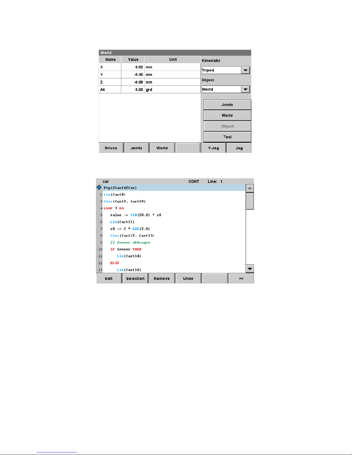
Example of the graphical interface, display of positions:
Example of the graphical interface, programming editor:
Please refer to the documentation on the handheld terminal software for additional
information.
6.6 User rights
The user has to log in with a user name and password to work with the handheld terminal.
This prevents unauthorised persons from gaining access to functions in the system. The
user account can be selected via the graphical mask. After the correct password has been
entered, all the released rights for the user are activated.
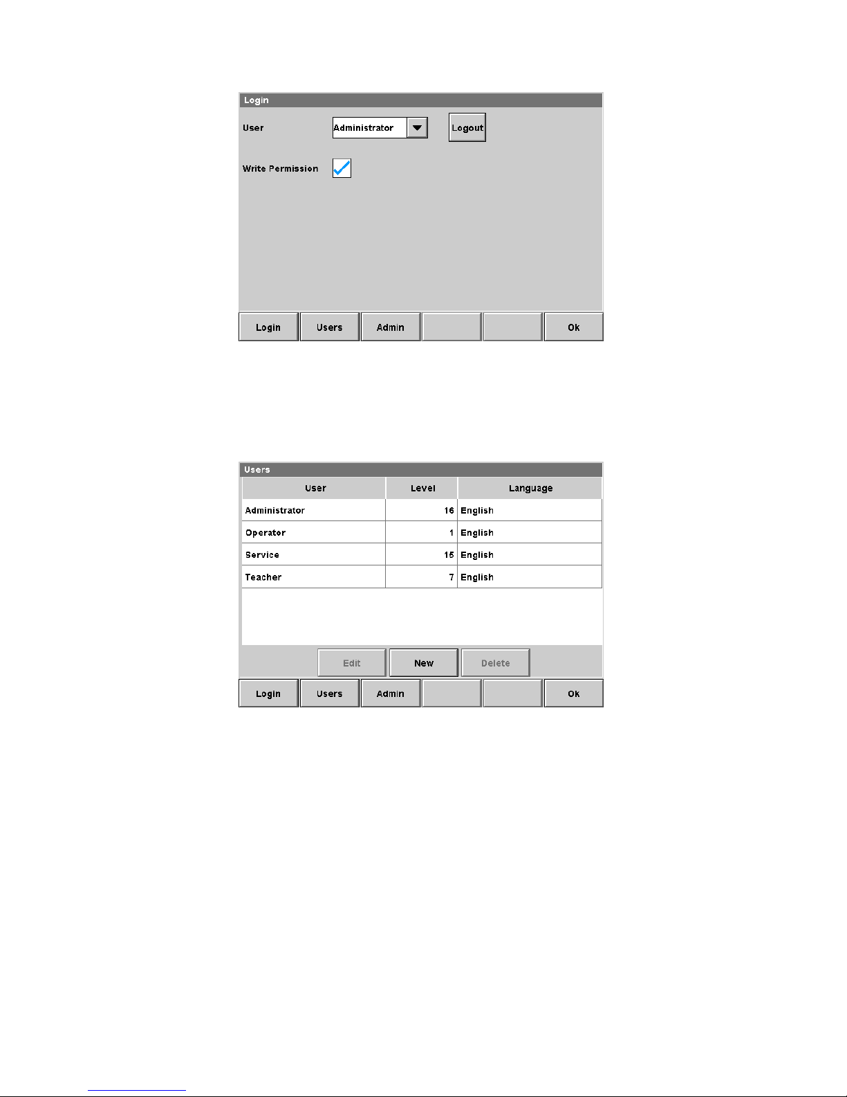
Design of graphical mask for selecting user:
Page 34
6. CDSA-D1-VX handheld terminal
34 Festo GDCP-CMXR-C2-SY-EN 1205b
New user accounts can be created via user administration. Every user is allocated a
password and a rights level in the process. The user rights are divided into levels 1, 7, 15
and 16. Level 16 has all rights and should be reserved for the administrator.
Design of graphical mask for user administration:
6.6.1 User levels
In the CMXR multi-axis control system, a user level consisting of several levels between 1
and 15 can be allocated to every user. The highest level 16 has no restrictions, it should be
reserved for the administrator.
Page 35

6. CDSA-D1-VX handheld terminal
Festo GDCP-CMXR-C2-SY-EN 1205b 35
List of functions with the required user level
Menu button
Function
Level
Write
Setup
Settings mask
1 - User
User mask
1 - Display
Setting display properties
1 - System
Pop-up menu for system settings
15 - Disable
Disables the touch function for 10 seconds
1 - Report
Service area
1
Yes
I/O monitor
Displays the input and output signals
7
-
Table 6.4 Service area
Menu button
Function
Level
Write
Variables
Monitor mask for variables
1 - Variable
Pop-up menu for manipulating
7
Yes
Clean up
Deletes unused variables
7
Yes
Check use
Check use of variables
7
Yes
Teach
Teach position variables to the current position
7
Yes
Table 6.5 Variable function
Menu button
Function
Level
Write
Project
Project mask
1 - Load
Load project / program
1
Yes
Open
Open project / program (translate only)
1
Yes
Close/End
Close project / End program
1
Yes
Info
Display program information
1 - Update
Update project view
1 - File
File manipulation functions
7
Yes
Configuration
Execution mask
1 - View
Display selected program
1 - Step/Cont
Switching Step / Continue
7
Yes
End
End program
1
Yes
Table 6.6 Project functions
Page 36

6. CDSA-D1-VX handheld terminal
36 Festo GDCP-CMXR-C2-SY-EN 1205b
Menu button
Function
Level
Write
Program
Program mask
1 - Modify
Modify selected program line
7
Yes
Macro
Repeast last insertion command
7
Yes
New
Insert new FTL command
7
Yes
PC
Set sentence pointer
7
Yes
Step/Cont
Switching Step / Continue
7
Yes
Process
Program processing functions
7
Yes
Selection
Select lines for cutting out or copying
7
Yes
Delete
Delete selected lines
7
Yes
Undo
Undo the last operation
7
Yes
Text editor
Text editor mask
7
Yes
Table 6.7 Program functions
Menu button
Function
Level
Write
Positions
Robot position mask
1 - Drives
Display drive positions
1 - Axes
Display robotic axis positions
1 - World
Display positions in the World coordinates
1 - Object
Display positions in the Object coordinates
1 - V-Jog
Set jogging speed
1
Yes
Jog
Set Jog coordinate system
1
Yes
Table 6.8 Robot status and functions
Menu button
Function
Level
Write
Messages
Message mask
1 - Acknowledge
Acknowledge selected message
1
Yes
All
Acknowledge all messages
1
Yes
Display
ID display of ID numbers instead of texts
1 Help
Display help for selected message
1 - Message
Mask for message log
1 - Display
ID display of ID numbers instead of texts
1 Help
Display help for selected message
1
-
Table 6.9 Message functions
Page 37
6. CDSA-D1-VX handheld terminal
Festo GDCP-CMXR-C2-SY-EN 1205b 37
6.6.2 Set users on delivery
Four user accounts are automatically set up during the installation of the CMXR multi-axis
control system. These users serve as a basis for further settings. User accounts can be
created, modified or deleted via the privileged “Administrator” user. Please refer to the
documentation on the handheld terminal software for additional information.
User name
Password
User level
Administrator
admin
16
Service
service
15
Teacher
teacher
7
Operator
operator
1
Table 6.10 Set users on installation
When the CMXR system is restarted or after the user has logged out, a so-called default
user is activated that possesses Level 1. This user is set up internally and active only when
no user from the supplied list is active.
Note
After the system starts up, the default user is active with the
configured language.
Note
The “Service” user is required by the system and must not be
deleted. It cannot be used for working on the system.
Note
The same users accounts are valid for accessing the CMXR multiaxis control system via a network connection (connect network
drive). Nevertheless, the user rights are insignificant for these
services. A network connection can be established with the relevant
password by every user.
6.7 Communication with the CMXR multi-axis control
system
Communication between the handheld terminal and the CMXR multi-axis control system
takes place via the Ethernet interface using permanently set IP addresses.
Should communication with another CMXR multi-axis control system be established, then
the handheld terminal must be reconnected to the interface unit for the required system.
It is true to say that communication can be established via the setting of another Ethernet
address, but this is not feasible due to the hardware signals for the permission buttons,
since these are wired via a hardware solution.
Page 38
6. CDSA-D1-VX handheld terminal
38 Festo GDCP-CMXR-C2-SY-EN 1205b
Note
It is only possible to communicate with the CMXR multi-axis control
system that accommodates the interface unit, since the hardware
signals of the permission buttons have to be assigned according to
a kinematics system.
Note
An interface unit is needed for every CMXR multi-axis control
system so that communication can take place with the handheld
terminal.
6.7.1 Synchronisation of dialogue software
The power supply is established when a handheld terminal is connected to the interface
unit, and communication to the CMXR multi-axis control system is set up. The dialogue
software for the handheld terminal can be found on the memory card of the central control
unit. To operate the handheld terminal, the software is loaded onto it and stored there.
Every time the handheld terminal is run up, the software versions on the handheld terminal
and the CMXR central control unit's memory card are compared with each other. Should
these differ, then the software is loaded onto the handheld terminal. This requires a little
bit of time.
Note
The dialogue software for the handheld terminal is stored on the
memory card for the central control unit and in the handheld
terminal. Should the versions differ, then the software from the
memory card is loaded onto the handheld terminal.
6.8 IP addresses on delivery
Communication between the CDSA handheld terminal and the CMXR is taken care of via
Ethernet. The CDSA handheld terminal has the following settings on delivery:
Network parameter
Value
IP address (CDSA)
192.168.100.101
Subnet mask
255.255.255.0
Gateway address
0.0.0.0
Host IP (CMXR)
192.168.100.100
The addressing for the delivery status is married to the delivery status of the CMXR. If
these devices are operated together, without network integration, then no settings are
necessary in the IP addresses.
Page 39
6. CDSA-D1-VX handheld terminal
Festo GDCP-CMXR-C2-SY-EN 1205b 39
Note
If the handheld terminal is integrated in a network, then make sure
that the addressing is correct. In this case, the delivery status
settings must be changed.
Note
The CMXR multi-axis control system is not DHCP-capable. It must
be configured via FCT.
6.9 Screen control
If no task is undertaken at the touchscreen, then the background illumination is reduced
after approx. two minutes to protect the display. The screen saver is activated after
approx. 10 minutes. The touchscreen is reactivated when it is touched.
Note
Touching the display deactivates the reduced background
illumination or screen saver. Full illumination is activated.
6.10 CDSA emulation
With the FCT plug-in CMXR, a CDSA emulation is installed on the PC. This emulation has
functionally the same performance as the operator unit CDSA-D1-VX and can be operated
in the same way.
Caution
The CDSA emulation is strictly a PC application. It does not have the
safety equipment of the operator unit CDSA-D1-VX.
The emergency off and permission button function must be ensured
in some other way.
Page 40
7. Drive systems
40 Festo GDCP-CMXR-C2-SY-EN 1205b
7. Drive systems
Only Festo electric motor controllers are used for operating the kinetics. Both the Festo
servo motor technology and the Festo stepper motor technology can be used in the
process. The following Festo motor controllers are currently supported:
Type
Meaning
CMMP-AS
Festo Premium motor controller for servo motors
CMMS-AS
Festo Standard motor controller for servo motors
CMMD-AS
Festo double motor controller for servo motors
CMMS-ST
Festo motor controllers for stepper motors
Table 7.1 Supported Festo motor controllers
Note
The node address of the kinematic axes is continuous and
permanently specified by the system. Therefore, when using the
CMMD-AS, make sure that the motor controller is used exclusively
for successive axes of one kinematics system.
Communication to the motor controllers takes place via the Festo DriveBus, which is based
on the CANopen DS402 – “Interpolated Position Mode” operating mode.
7.1 Configuration of the motor controllers
Every motor controller is parameterised with its assigned FCT plug-in (module in the Festo
Configuration Tool FCT software). A basic functional commissioning of every participating
axis is required prior to shared operation with the CMXR multi-axis control system. Special
features for the parameterisation of motor controllers:
Control interface: DriveBus
Error management: The “Hardware limit switch” group must not be set to “Warn”
or “Ignore”.
7.2 CAN bus address for motor controllers
When communication takes place via the Festo DriveBus at interface CAN X6, the CMXR
multi-axis control system is the master; all motor controllers are operated as slaves. The
bus address for the motor controllers is determined and defined as follows:
From CAN-ID 2 and ascending: motor controllers for all basic axes
Following without gaps: motor controllers for all wrist axes
Following without gaps: motor controllers for all auxiliary axes
If there are a maximum of six permissible axes, the CAN addresses 2 … 7 are assigned.
Page 41

8. Operating modes
Festo GDCP-CMXR-C2-SY-EN 1205b 41
8. Operating modes
The CMXR multi-axis control system has two operation modes:
Manual override with reduced speed
Automatic mode
Caution
The reduced speed in manual override is not a safe function.
Additional external protective measures that ensure the safe
operating condition of the entire system even in the event of a
malfunction must be adopted for safety-related control tasks or for
the safety of personnel.
The operating mode is selected via the respective digital input (e.g. a key actuator). The
active operating mode is displayed with a digital output signal.
Depending on regulations, the signals for the operation modes are generated via a safetyrelated logic, since under certain circumstances this safety-related logic must have the
appropriate status for activating an operation mode.
8.1 Manual override
This operation mode is used for setting up the kinematics and commissioning the
programs. It is generally carried out with the handheld terminal. The speed is limited
(e.g. the path speed for the TCP to a maximum 250 mm/s). This speed restriction is not
safe. Additional external protective measures must be adopted for safety-relevant control
tasks or for the safety of persons.
Functions in manual mode:
- Moving the kinematics system at reduced speed. Pressing down the enabling button is
a requirement for this. Without CDSA, manual override is possibly only if a
corresponding hardware control is provided by the user.
- For Cartesian movements, a maximum 250 mm/sec on TCP.
- For the movement of individual linear axes, a maximum 250 mm/sec.
- For the movement of individual rotating axes, it must taken into account for the
projecting component that 250 mm/sec are not exceeded at the longest end. The
rotational speed of the axis must be calculated in proportion to this length and
must be entered in the configuration.
- Teaching of positions
- Generating and modifying programs
- Testing programs in the step mode or continuous mode at reduced speed. Pressing
down the permission button is a requirement for this
Page 42
8. Operating modes
42 Festo GDCP-CMXR-C2-SY-EN 1205b
Note
The values for the reduced speed must be configured via Festo
Configuration Tool (FCT). It is here that limits for the maximum
speeds are specified according to the parameter.
The integrated 2-channel, 3-stage enabling buttons are used for manual travel using the
handheld terminal. These are connected to the CMXR multi-axis control system via a digital
input.
8.2 Automatic mode
In automatic mode, all movements of the kinematics are processed at full speed. All
dynamic values set in the program are processed and run.
Caution
Considerable speeds can be generated in automatic mode. To
execute this operation mode, the valid regulations and safety
devices for operating the kinematics must be observed.
It is not possible to move the axes manually in automatic mode. The handheld terminal's
permission buttons are not taken into account.
8.3 Stopping the kinematics, EMERGENCY-STOP
The kinematics are stopped on the path. This means that all the axes participating in the
interpolation brake together up to standstill. To do this, the CMXR multi-axis control
system requires the emergency stop signal and the permission buttons' signal. If the CMXR
multi-axis control system does not brake the participating axes on the path in a coordinated way, then this could result in collisions - for example, with the tool.
A coordinated stop on the path can only take place if all the necessary axes for this are
ready for operation, i.e. do not have any errors. If there is an error in the axis, then the axis
cannot be stopped true to the path. The axis normally stops the drive itself as a consequence of the error. In such a case, a deviation from the path will occur which cannot be
influenced by the CMXR multi-axis control system.
Caution
An uncoordinated stop of the axes can trigger collisions, e.g. with
the tool, since the path is deviated from.
Page 43
8. Operating modes
Festo GDCP-CMXR-C2-SY-EN 1205b 43
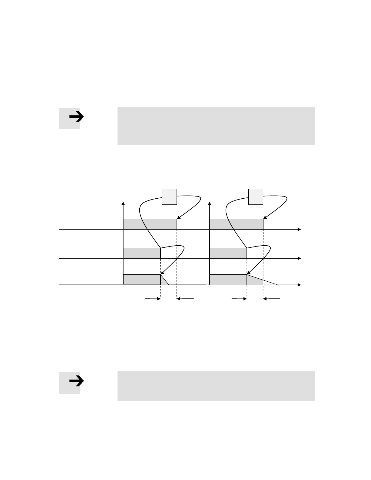
The CMXR multi-axis control system needs time to stop the axes true to path. This period
of time commences as from the emergency stop signal until the power of the drives are
shut down after a defined and permissible duration via a safety-related module. The CMXR
multi-axis control system must stop the drives true to path within this period of time. If it
does not succeed in doing this, the safety-related module will most certainly intervene and
shut down the power in the drives.
Note
The CMXR multi-axis control system brakes with the maximum
possible path values feasible, as determined by the axis dynamics.
This must be taken into account when calculating a braking time.
The following graph shows the signals for shutting down the drives and for the true-topath stop of the kinematics axes:
A true-to-path stop is possible in the left part of the graph. In the right part, the drive
power is shut down via the safety-related hardware, e.g. a 2-channel time relay.
Note
The applicable regulations must be observed when setting the
delay time for shutting down the drive power via the hardware.
Motion
Drive enable regulator
Emergency stop signal
Time suffices for true-
to-path stop
t
Time does not suffice for true-to-path
stop, axes are stopped via the drive
regulator
t
Page 44

8. Operating modes
44 Festo GDCP-CMXR-C2-SY-EN 1205b
8.4 Repositioning
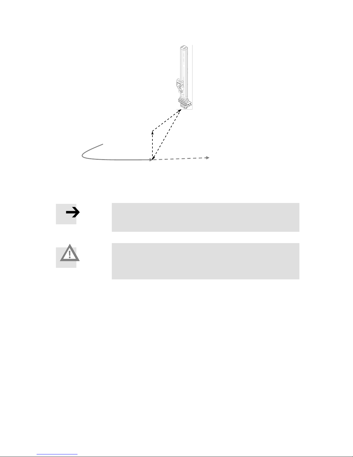
The CMXR multi-axis control system has the “Repositioning” function. This is understood
as the automatic approach to a point where a program was interrupted and is now to be
continued. The interrupt point is automatically approached.
A kinematics system can leave the path, for example, as a result of
- the kinematics axes bending, e.g. when the brakes engage
- or a manual movement of the kinematics.
After a program has been restarted, the kinematics are moved directly from the actual
position to the interrupt position. If the kinematics were moved manually, this could lead
to a collision when repositioning. For this reason, you must take care to avoid a collision
when repositioning.
Caution: Danger of collision
Repositioning is carried out directly. This means that the axes move
from the current position to the interruption position by the direct
route.
To minimise the danger of collision, it is recommended that you
move the kinematics manually into the proximity of the interruption
position prior to repositioning. At the same time, any orientation
axes should also be moved into the approximate orientation
position they were in when the interruption took place.
Repositioning is carried out at a defined speed. This is configured via the Festo
Configuration Tool (FCT). It is recommended that moderate dynamic values that can be
controlled are set here.
Note
When configuring the dynamic values, make sure the values are
reasonable and can be controlled.
Page 45
8. Operating modes
Festo GDCP-CMXR-C2-SY-EN 1205b 45
Note
Depending on the type of kinematics, a PTP or a Cartesian linear
interpolation is used for repositioning.
Caution: Danger of collision
If repositioning is carried out using a Cartesian linear interpolation,
then defined tools are taken into account on the path. This can lead
to unexpected compensating movements in the kinematics.
Interrupt position on the
path
Intermediate position
Direct repositioning
movement
Travelling from the path, e.g.
by moving manually
Page 46
9. Activation method
46 Festo GDCP-CMXR-C2-SY-EN 1205b
9. Activation method
The multi-axis control system CMXR-C2 - besides the handheld terminal - always be
actuated via the integrated CoDeSys controller. If an additional controller is to be assigned
a higher order, this can be realised via the access routes digital I/O, PROFIBUS DP,
Ethernet TCP/IP or CAN by means of CoDeSys modules.
The template “CMXR Stand-alone” is saved as the minimum configuration. You can find
additional information about this topic in the “CMXR with CoDeSys” manual.
9.1 CMXR-C2 in stand-alone mode
In stand-alone mode, the motion control is controlled by the handheld terminal, but some
important signals have to be additionally transmitted via the internal PLC and its RC
interface to the motion control. The signals are mapped in the CoDeSys project template
directly onto the configured first I/O card. Then the project can be loaded and started
without any extension directly on the controller.
Note
The system signals can also be processed directly in CoDeSys, in
which case an I/O card is not absolutely necessary.
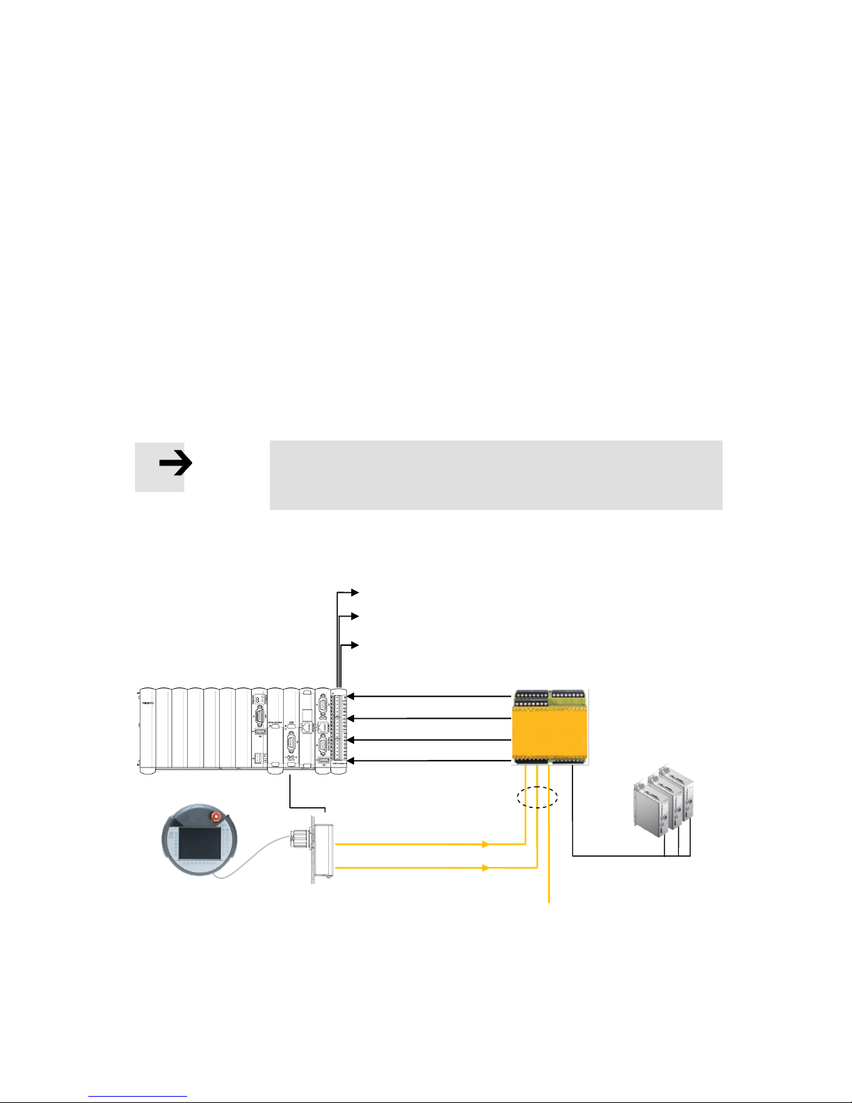
The following illustration shows an example for installation in stand-alone mode:
CMXR-C2
Example of safety technology
CAMI-C
interface unit
Handheld terminal
CDSA
Automatic operation mode
Manual operation mode
Emergency stop signal
Permission button
Permission button
Emergency stop signal
Additional emergency
stop signals
2-channel design
Drive units
Drive enable
Feedback signal for Manual override operation mode
Ethernet
Feedback signal that error is active
Feedback signal for Automatic operation mode
Page 47
9. Activation method
Festo GDCP-CMXR-C2-SY-EN 1205b 47
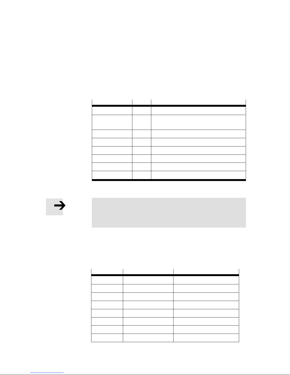
In this example, the drive enable is triggered via an emergency stop signal by means of the
safety technology. This logic element has the capacity to set a time delay for achieving a
delayed shutdown for the drive enable. With the feedback signal for the active operation
mode or if an error is active, a signalling element, e.g. a lamp, can be activated.
The following table contains all the components that are recommended for the activation
method “Stand-alone with CoDeSys”. The number of peripheral modules can be adapted
to the respective application.
Type
No. of
Meaning
CMXR-C2
1
Central control unit
CECX-D-8E8A-NP-2
1
Digital mixed module with eight inputs and eight
outputs
NECC-L1G2-C1
2
2-pin plug
NECC-L1G8-C1
2
8-pin plug
CDSA-D1-VX
1
Handheld terminal
NESC-C-D1-5-C1
1
Cable for handheld terminal, e.g. 5m
CAMI-C
1
Interface unit for handheld terminal
NECC-L1G11-C1
1
11-pin plug for interface unit
Table 9.1 CMXR components, stand-alone mode with CoDeSys
Note
In stand-alone mode, at least one additional central input/output
module CECX-D-8E8A-NP-2 at the multi-axis control system
CMXR-C2 is recommended.
9.1.1 System signals
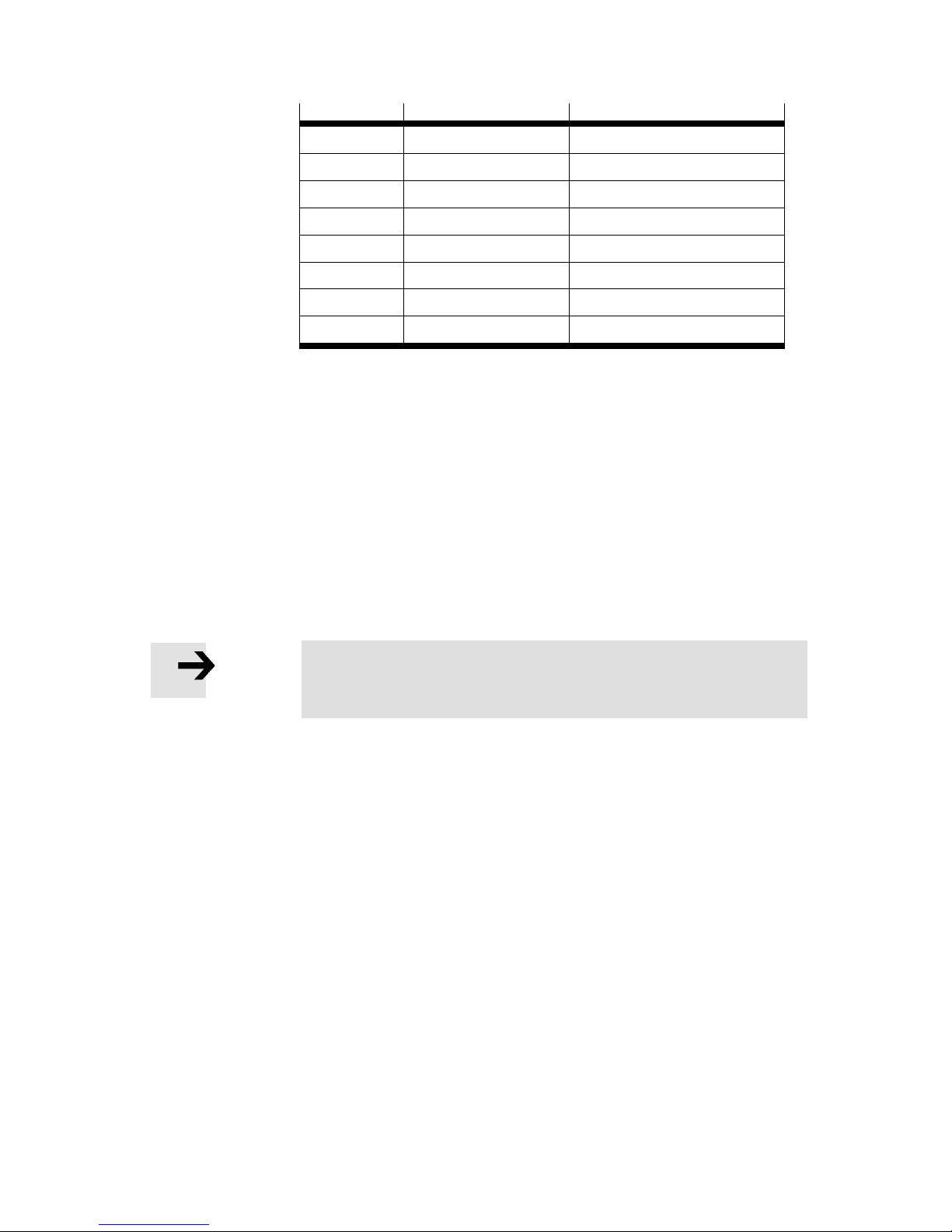
The table below includes the system signals and the signal assignment of the recommended I/O card CECX-D-8E8A-NP-2.
Signal
Signal name
Meaning
Output 0
doutError
Error active
Output 1
Freely usable
Output 2
doutAutoSelected
Automatic operation mode active
Output 3
doutManSelected
Manual operation mode active
Output 4
Freely usable
Output 5
Freely usable
Output 6
Freely usable
Output 7
Freely usable
Page 48
9. Activation method
48 Festo GDCP-CMXR-C2-SY-EN 1205b
Signal
Signal name
Meaning
Input 0
dinEmStop
Emergency stop
Input 1
dinEnabling
Permission button
Input 2
dinAutoSelected
Automatic operation mode
Input 3
dinManSelected
Manual operation mode
Input 4
Freely usable
Input 5
Freely usable
Input 6
Freely usable
Input 7
Freely usable
Table 2: Allocation of the system signals
The I/O points allocated on the I/O card with “Signal name” are allocated as the default
proposal. The free inputs and outputs can be used as application signals. The symbols are
allocated to the I/O points via the Fest Configuration Tool (FCT).
9.2 Higher-order controller and write permission
The CMXR multi-axis control system can be controlled via an internal PLC or via the
handheld terminal. To avoid any problems, only one of the devices has the right to actively
control the CMXR multi-axis control system, e.g. to start programs. This active participant
has the status of “higher-order controller” and thus has write permission. A passive
observer role for each of the devices is always an option.
Note
Only one device can actively control the CMXR multi-axis control
system.
9.2.1 Mode of operation
Higher-order control is managed in the motion control of the CMXR. After running up the
system, none of the possible controlling devices has the higher-order control and thus the
write permission. This must firstly be requested. The request is carried out via a dialogue
on the handheld terminal or via a signal exchange with the internal PLC control system. All
stations have the same rights here. The device that requests first receives the higher-order
control. If a device no longer needs the higher-order control, it must return it to administration. Removal of the higher-order control is not possible.
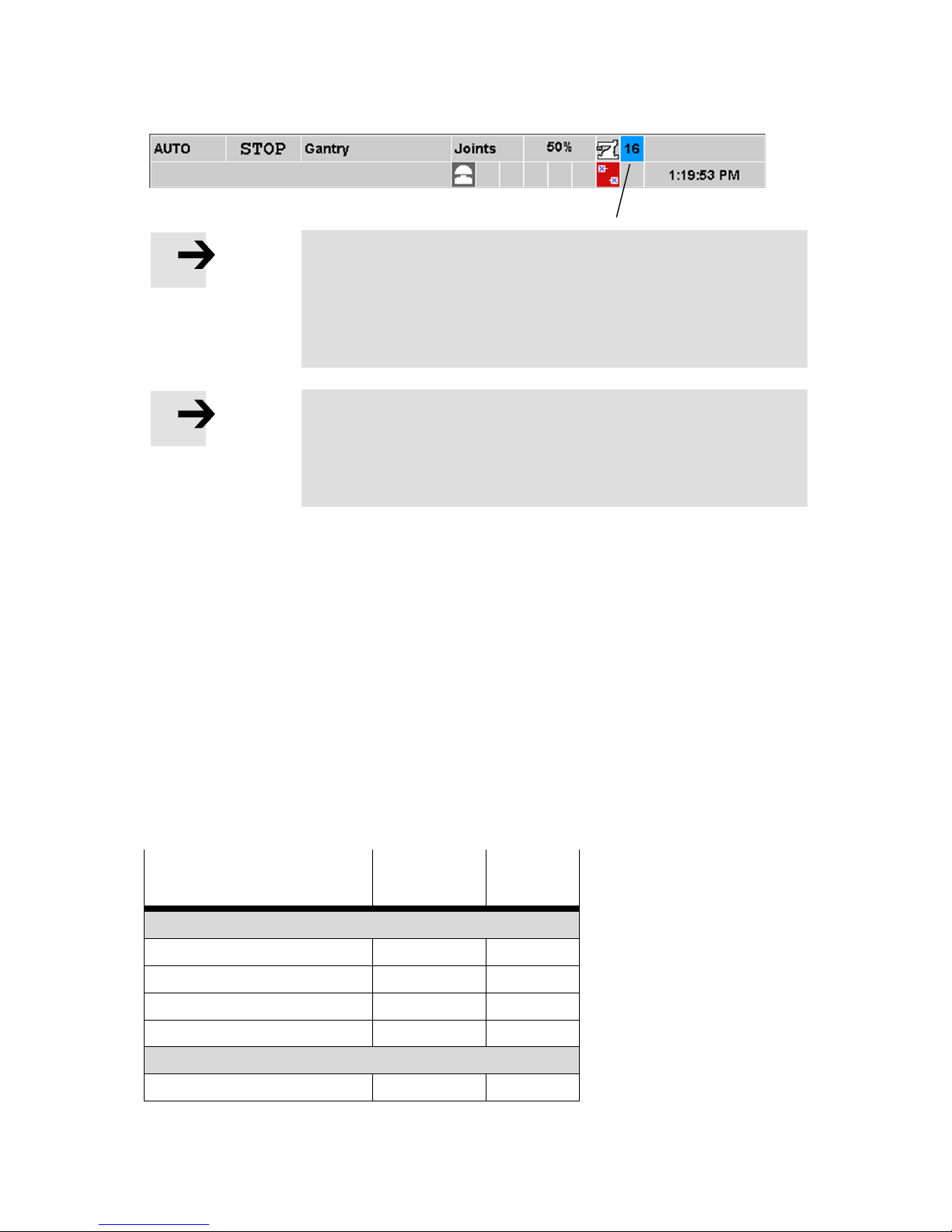
The status of the higher-order controller of the teach pendant is shown with the
background colour in the field of the active user level:
Background colour = grey: no write permission/no higher-order controller present
Background colour = blue: Write permission/higher-order controller present
These states are also transmitted on the interface for the external control system.
The following illustration shows how this is represented graphically on the handheld
terminal.
Page 49
9. Activation method
Festo GDCP-CMXR-C2-SY-EN 1205b 49
Note
Every controlling device must request the higher-order control itself
and return it as required. Removal of the higher-order control is not
possible. Should the communication with a device be interrupted,
then the higher-order control is returned to administration after an
internal timeout.
Note
If there is no connection to a control system and operation is
carried out via the CDSA handheld terminal, then the higher-order
control has to be requested once on the handheld terminal after
the control system has been started up
9.2.2 User level
The higher-order control is independent of the operation mode and the user level for the
operator unit. Even with user level 16 (Administrator), control can only take place using an
active higher-order control; a transfer of the higher-order control without the controlling
participant previously returning the control sovereignty is not possible.
9.2.3 Influence of the higher-order control
The higher-order control effects the possible extent of action of a participant. Each
participant can always carry out passive actions, i.e. it can observe but not execute any
influence on programs or the kinematics. Furthermore, the options are dependent upon
the active interface. The following table provides an overview of the active and passive
functions of the individual connections and participants.
Function
Handheld
terminal CDSA
CoDeSys
Active functions with write permission
Jogging of axes
X X Teaching of positions
X X Starting and stopping programs
X X Delete errors
X X Passive functions without write permission
Mode selection
X
Field of active user levels
Page 50
9. Activation method
50 Festo GDCP-CMXR-C2-SY-EN 1205b
Function
Handheld
terminal CDSA
CoDeSys
Permission button signals,
emergency stop
X
X
Exchange of cyclic I/O data
X Observing variables
X X Writing variables
X
X
Table 9.3 Overview of active and passive functions
9.2.4 Integration example
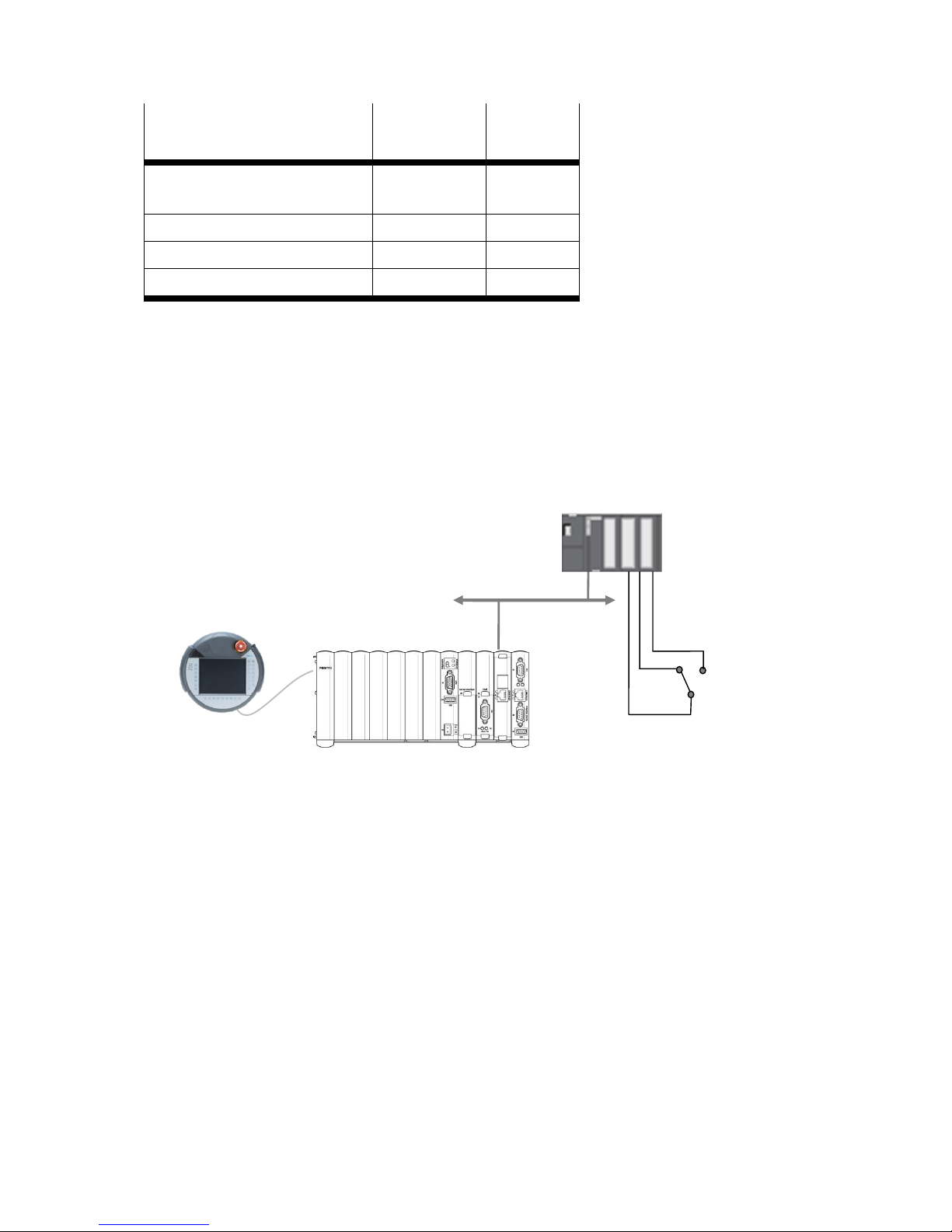
When controlling via an external control system it is recommend that a selector switch be
installed on the external control system for requesting the higher-order control or for
enabling other participants (handheld terminal). The status of the higher-order control
could be visualised via a light signal.
Depending on the status of the selector switch, the external control system obtains the
higher-order control or gives it back to administration. It is also possible to integrate this
higher-order control into a selection of operation modes, e.g.:
- Manual override without higher-order control
- Manual override with higher-order control
- Automatic mode.
To execute automatic mode, the external control system always requires the higher-order
control, otherwise programs cannot be started, for example.
CMXR-C2
Handheld terminal
CDSA
Control signals
External control
Selector switch for enabling
handheld terminal.
Page 51
10. Coordinate systems
Festo GDCP-CMXR-C2-SY-EN 1205b 51
10. Coordinate systems
10.1 Axis coordinate systems
The axis coordinate system is a coordinate system that takes into account all physical axes
in a kinematics system. Each axis has a coordinate in the axis coordinate system. The
origin of a coordinate is in the zero point of the assigned axis.
In this position, the axis coordinate system is bound to the form and location of the
mechanical axes. This is determined by the mechanical design of the kinematics.
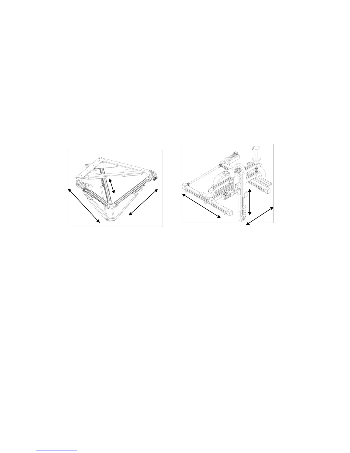
Examples:
The kinematic model of the Festo EXPT is illustrated in the picture on the left. The position
of the axes and thus the axis coordinate system is determined by the kinematic model.
The arrangement in the picture to the right shows a Cartesian kinematics system. This
mechanical system also has an axis coordinate system, although the axes standing
perpendicular to one another form a Cartesian system. In the axis coordinate system, the
CMXR multi-axis control system does not take the kinematic model into account, but rather
only the individual axes, which can be linear or rotary.
10.2 Cartesian coordinate systems
A Cartesian coordinate system comprises three axes standing perpendicular to one
another. The CMXR multi-axis control system uses a coordinate transformation to
calculate, using the internal kinematic model as a basis, the Cartesian world from the
individual axis coordinates.
10.2.1 Translatory axes X, Y, Z
In the Cartesian coordinate system, the three axes X, Y and Z standing perpendicular to
one another form the translatory axes. These are defined in accordance with the right-hand
rule.
A1
A3
A2
A1
A3
A2
Page 52
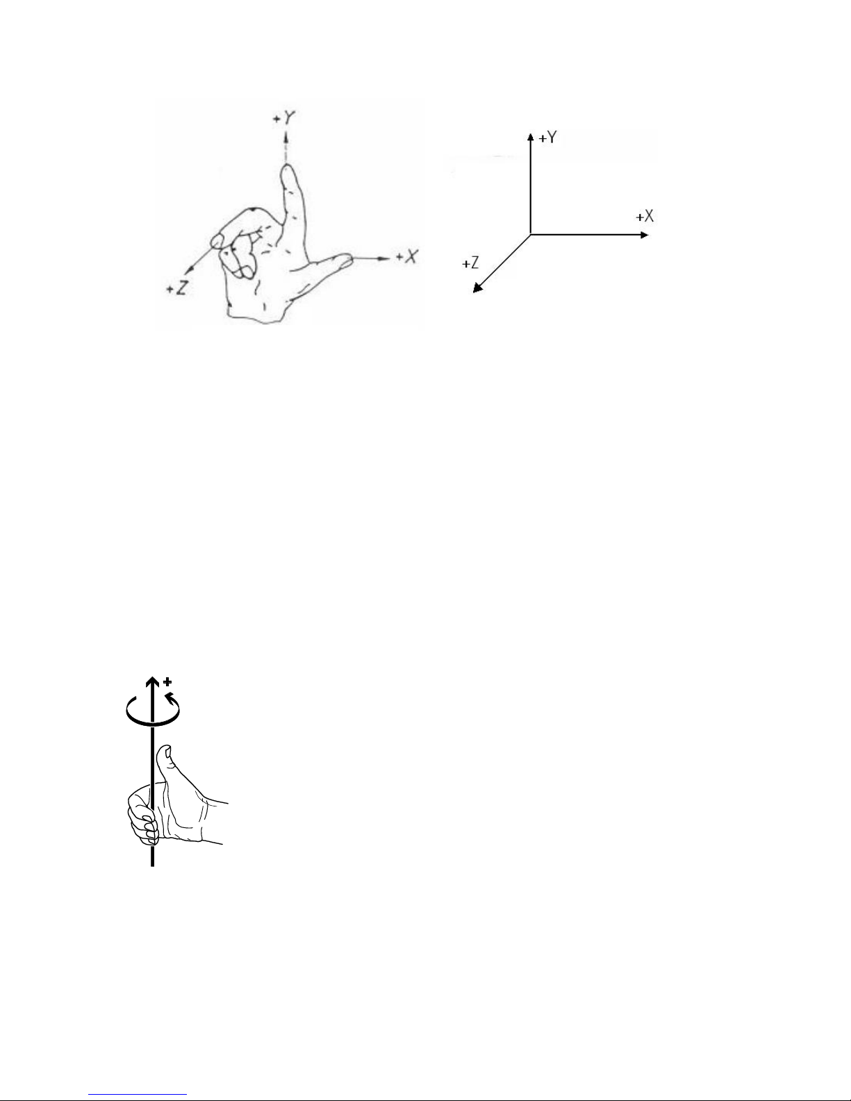
10. Coordinate systems
52 Festo GDCP-CMXR-C2-SY-EN 1205b
The thumb points to the positive X-axis, the index finger to the positive Y-axis and the
middle finger to the positive Z-axis.
With these three translatory axes, a tool, for example, can be moved or described in three
directions in the available space. They are known as the three degrees of freedom.
10.2.2 Orientation axes A, B, C
Using the translatory axes X, Y and Z, the position of a tool, for example, can be described.
Should this tool also have an orientation, however, i.e. the tool has turned away from its
original position, then this cannot be pressed out via axes X, Y and Z. To describe these
orientations, one needs rotating axes (= orientation axes) in the Cartesian system. These
execute a rotation around the translatory axes X, Y and Z.
The first axis of rotation in the Cartesian system is called “A”, the second axis of rotation
“B” and the third “C”. How the sequence of rotations is executed in the Cartesian system is
defined in accordance with Euler ZYZ with the CMXR multi-axis control system. This is
described in the following chapter.
The direction of rotation around the axis is defined by the right fist rule. This involves
making a fist with the right hand and raising the thumb upwards. In doing so, the thumb
indicates in the positive axis direction, the fingers in the fist indicate in the positive
direction of the rotation around the axis.
Page 53
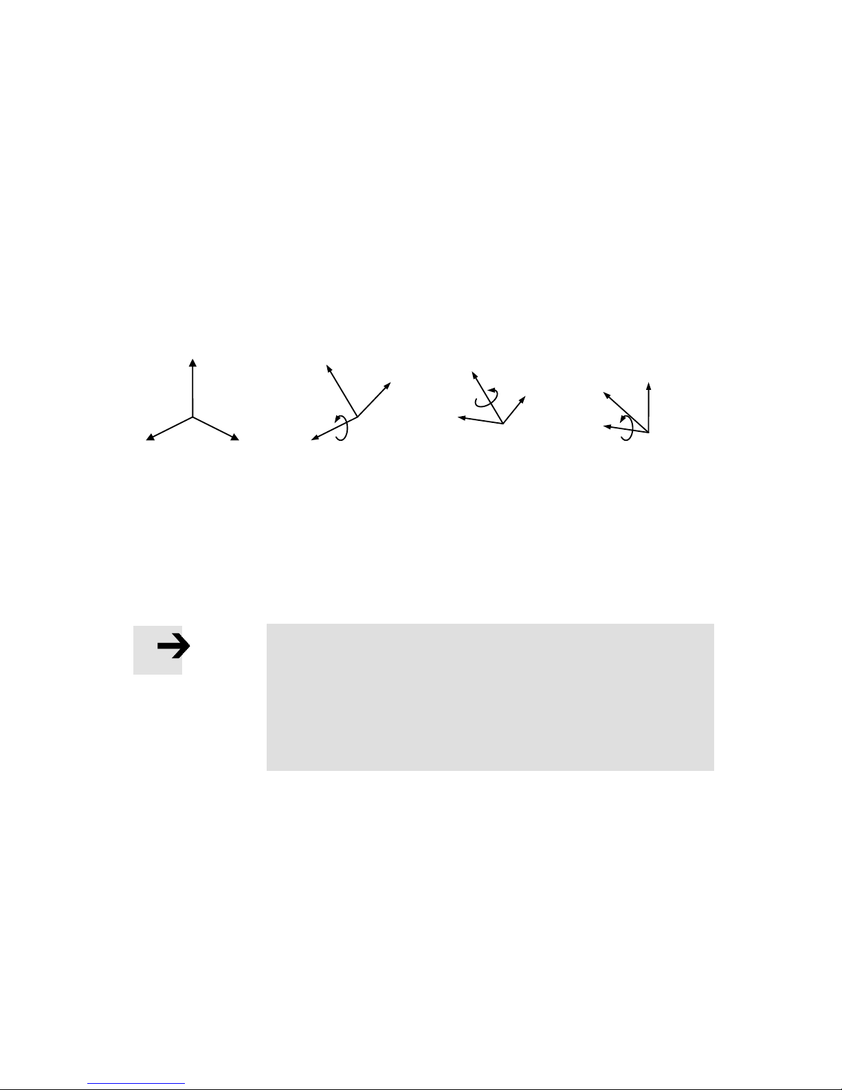
10. Coordinate systems
Festo GDCP-CMXR-C2-SY-EN 1205b 53
10.2.3 Euler orientation ZYZ
The Euler orientation describes a sequence of how an orientation is derived from a
Cartesian system. The CMXR multi-axis control system works in accordance with this ZYZ
Euler convention. This results in the following rotation sequence:
The first axis of rotation A rotates around the Z-axis,
the second axis of rotation B rotates around the Y-axis of the turned coordinate
system,
the third axis of rotation C rotates around the Z-axis of the once more turned
coordinate system.
The illustration shows the three rotation sequences in accordance with the ZYZ Euler
convention.
Owing to the two rotations around the Z-axis, the ZYZ Euler convention is proven to be
more easily understood than other rotation sequences. Because the tool axis is always in
the direction of the Z-axis, the orientation specifications can be understood in a practical
sense.
Note
The orientation according to Euler describes three orientation
degrees of freedom in the available space. However, these can only
be achieved if the mechanical system of the kinematics can fulfil
these degrees of freedom.
All orientation specifications in the CMXR system are always
specified in accordance with the ZYZ Euler convention.
10.3 Coordinate systems for the kinematics
10.3.1 Base coordinate system
The so-called base coordinate system for the kinematics is defined by virtue of the
arrangement of the axes in the available space and their parameterisation. It is a Cartesian
coordinate system. This is defined by
- the direction of rotation of the drives and
- the axis zero point,
Z
X
Y
Start position
X‘
Y‘
Rotation
around the Z-
Z‘‘
Rotation around the
turned Y-axis
Rotation around the
turned Z-axis
Z
X‘‘
Y‘
Z‘‘
X‘‘‘
Y‘‘
Page 54
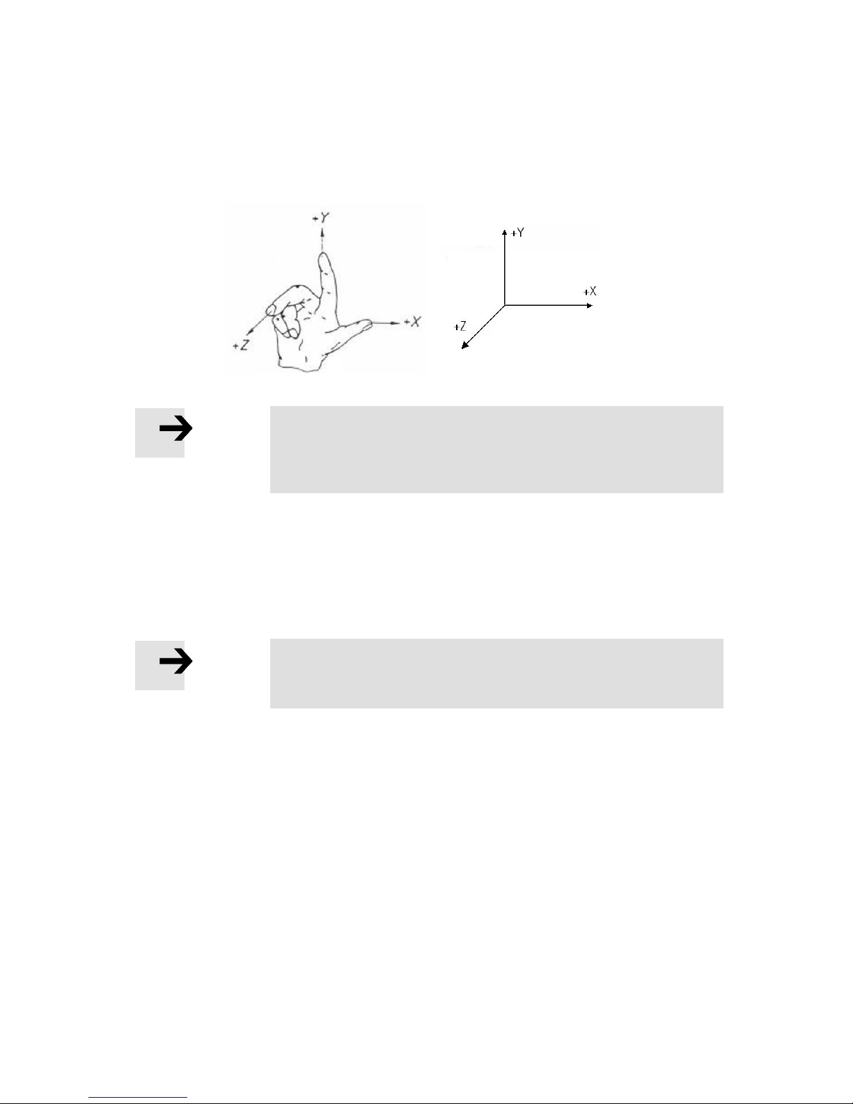
10. Coordinate systems
54 Festo GDCP-CMXR-C2-SY-EN 1205b
for example. The required settings are made in the configuration of the CMXR multi-axis
control system as well as in the configuration of the respective drive regulators. To ensure
that these settings can run, the directions of the Cartesian axes must always correspond
with the right-hand rule. If this is not adhered to, then the kinematics system cannot run in
combination with the CMXR control system.
Note
The settings of the parameters for the axes and drives, which affect
the coordinate directions, must comply with the right-hand rule,
otherwise they will not be able to run.
The position and orientation of the base coordinate system is determined by the
kinematics. Please refer to the description of the respective kinematics system for the
definition. All settings in the configuration must be made such that the definition for the
individual kinematics systems is fulfilled. The description for the individual kinematics
systems is shown in chapter “11 Supported kinematic systems”.
Note
All parameter settings, e.g. for the axes or drives, must be set such
that the specifications are fulfilled for the respective kinematics.
The following graphic shows a Festo three-dimensional gantry with its base coordinate
system whose origin is formed from the zero points of the individual axes.
Page 55
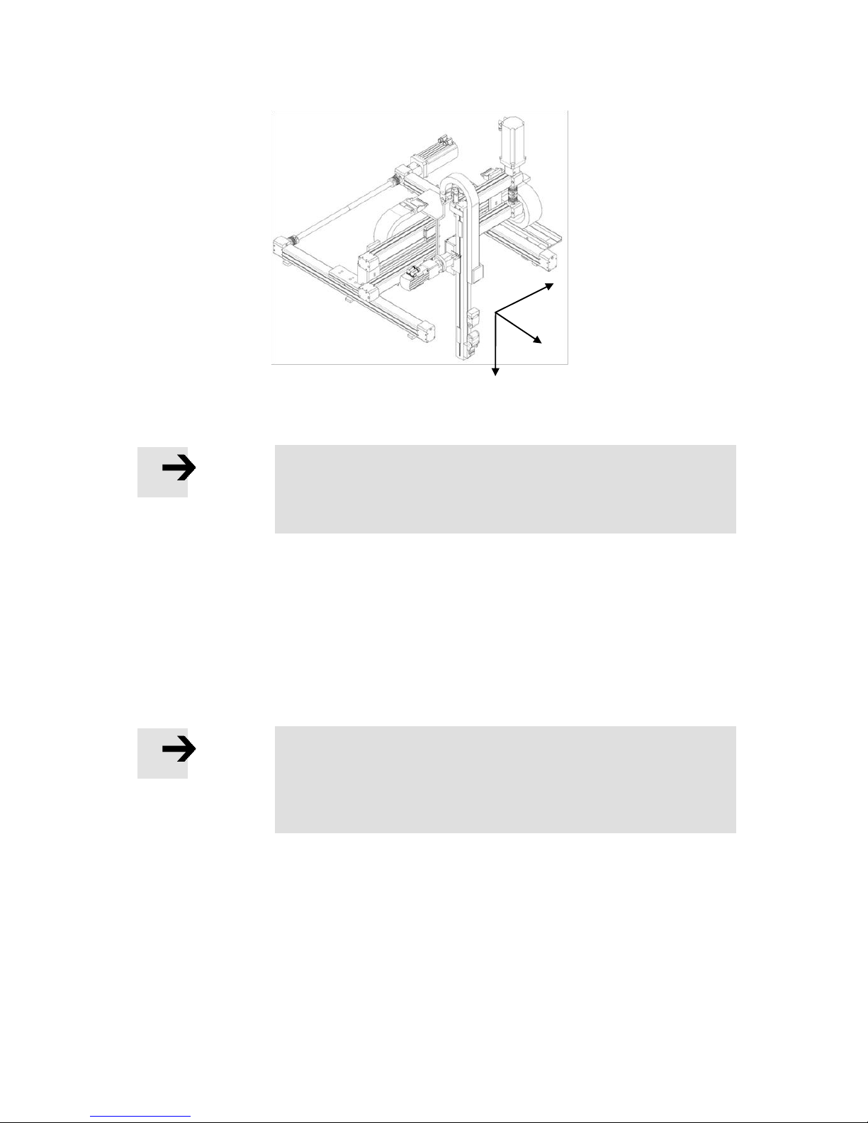
10. Coordinate systems
Festo GDCP-CMXR-C2-SY-EN 1205b 55
Note
The base coordinate system is, just like the global coordinate
system, Cartesian in its classification and is the Cartesian origin in
the kinematics.
10.3.2 Global coordinate system
The global coordinate system is defined with three degrees of freedom in the “World”. The
base and global coordinate system are congruent.
By shifting the base coordinate system, the global coordinate system could lie outside the
working space of a kinematics system. It is therefore possible that several kinematics
systems refer to the same zero point.
Note
Should a shift in the position or the orientation of the original base
coordinate system for the kinematics be necessary, then this can
be defined by a configurable offset via the Festo Configuration Tool
(FCT).
Example:
Two three-dimensional gantries are mounted on a shared conveyor system. There is a
common zero point on this conveyor system which applies to both kinematics systems.
The kinematics systems are distanced 2000 mm or 3500 mm in the direction of the X-axis
away from the global coordinate system.
X+
Y+
Z+
Base coordinate system
Page 56
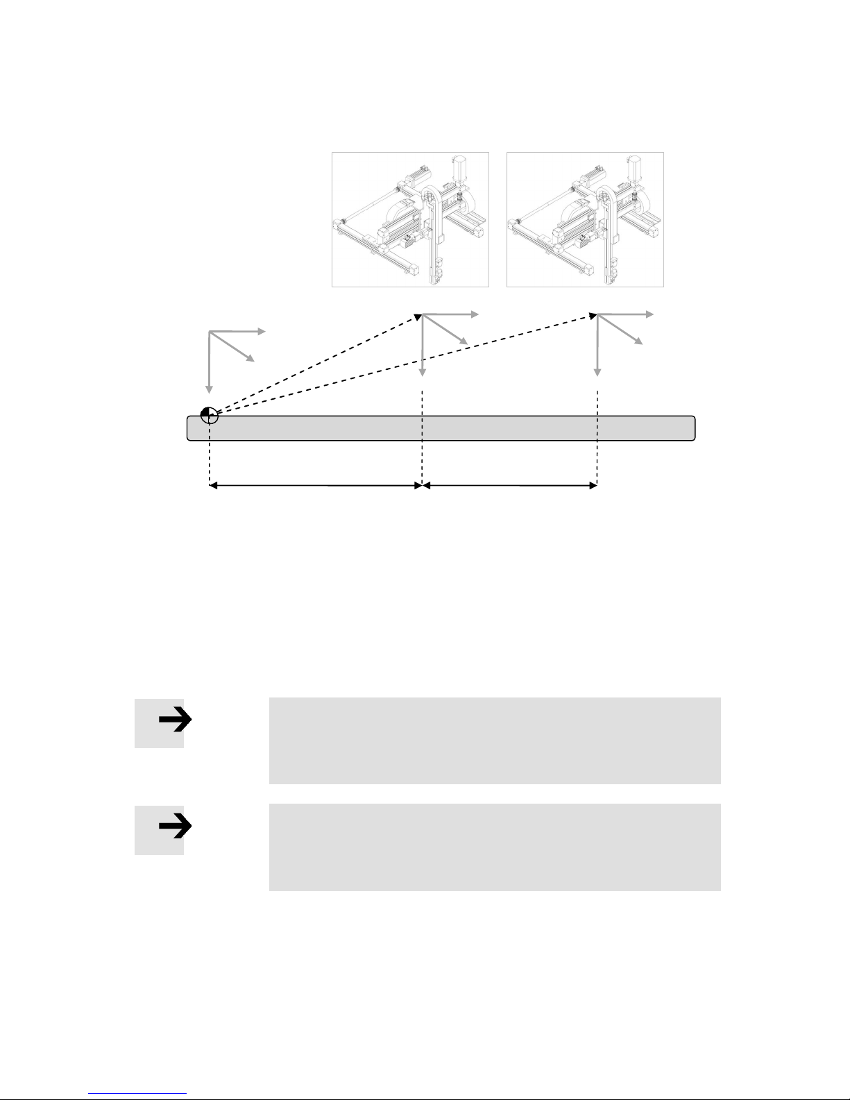
10. Coordinate systems
56 Festo GDCP-CMXR-C2-SY-EN 1205b
The offset of the base coordinate system for a kinematics system is defined from the
viewpoint of the origin of the global coordinate system. Simply put, you place the base
coordinate system into the global coordinate system, thus the two coordinate systems are
now congruent. The base coordinate system is now moved and/or oriented accordingly
away from the origin of the global coordinate system and into the required position.
This means for the example with the two three-dimensional gantries:
- Three-dimensional gantry 1 has a basic offset of X = 2000 mm
- Three-dimensional gantry 2 has a basic offset of X = 3500 mm
Note
The offset of the global coordinate system is a global setting for the
kinematics. Further zero point offsets that are only active during
program runtime can be defined in the movement program.
Note
If the base coordinate system is not offset, then the global
coordinate system is equal to the base coordinate system. In this
case, it is also called a global coordinate system.
Global coordinate system
Two three-dimensional gantries with base coordinate system
Conveyor system
X+
Y+
Z+
Y+
X+
Y+
X+
Z+
Z+
2000 mm
1500 mm
Page 57
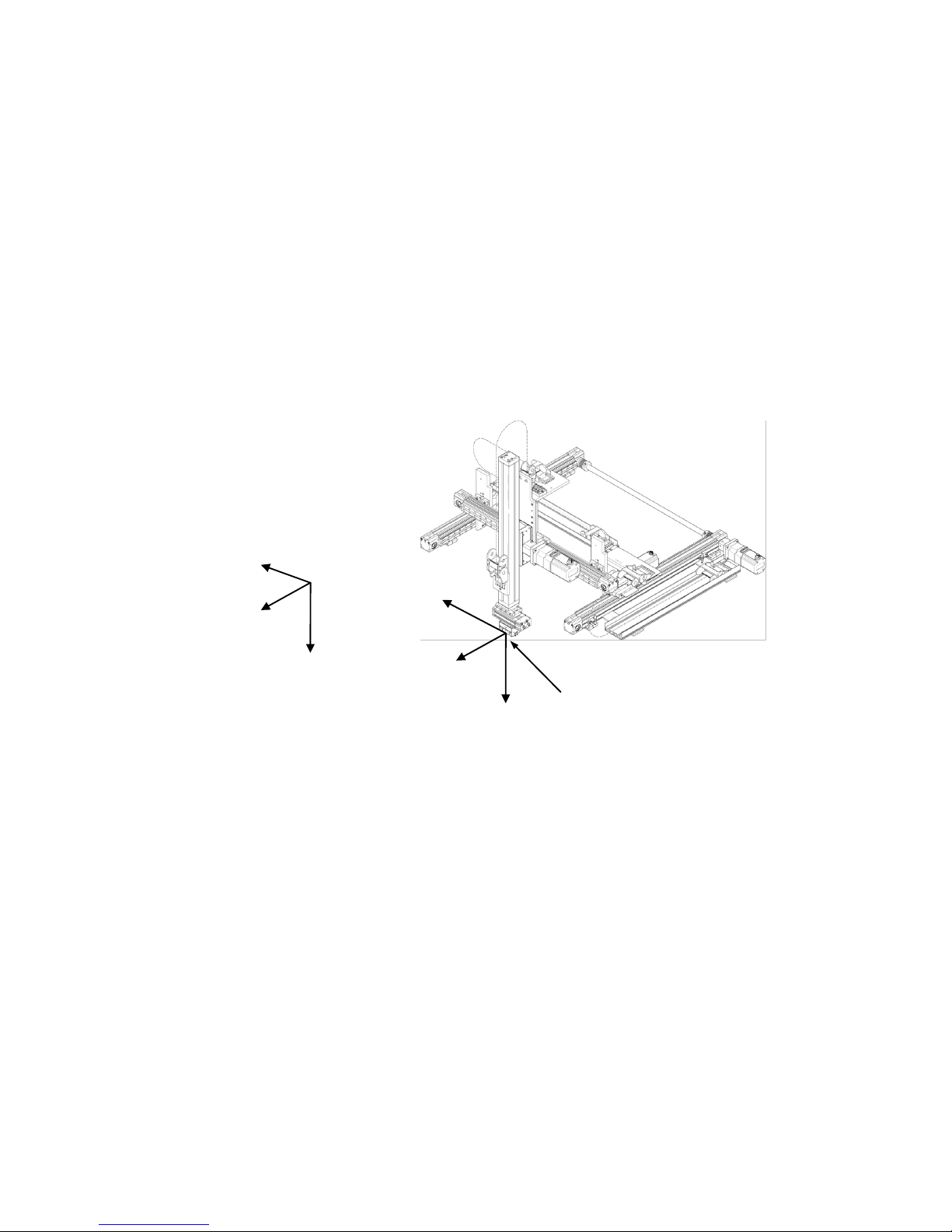
10. Coordinate systems
Festo GDCP-CMXR-C2-SY-EN 1205b 57
10.3.3 Tool coordinate system
The tool coordinate system is a Cartesian system and has three translations and three
orientation specifications, in total six degrees of freedom. The origin of the tool coordinate
system is normally on the tool flange of the kinematics. This origin is dependent on the
kinematics model. Please refer to the description of the kinematics for additional
information.
The orientation of the tool coordinate system is initially the same as the orientation of the
base coordinate system. The definition of a tool or the use of an orientation axis can be
used to define the tool coordinate system in the available space.
The following illustration shows a three-dimensional gantry with base and tool coordinate
system:
The origin of the tool coordinate system forms the tool operating point and is known as the
Tool Center Point (TCP). Using a tool definition, the TCP can be defined with six degrees of
freedom. This definition can be used to set the TCP to any tool in the available space. This
defined TCP is guided on the path during Cartesian movements.
10.3.4 Working with the tool coordinate system
The tool coordinate system can be used to work entirely in manual override. This operating
mode can be selected, for example, via the CDSA handheld terminal. The tool coordinate
system is only significant for teaching positions and manual operation. If positions are
complete, they are stored as Cartesian or axis positions depending on the variables used.
X+
Y+
Z+
Ty+
Tx+
Tz+
Base coordinate system
Tool coordinate system
Tool operating point (TCP)
Page 58

10. Coordinate systems
58 Festo GDCP-CMXR-C2-SY-EN 1205b
Note
If positions are complete with a selected tool coordinate system,
then these positions are stored as Cartesian or axis positions.
If the tool coordinate system is selected (e.g. on the CDSA handheld terminal), then the
kinematics can be moved with its TCP inside the defined tool coordinate system. In addition to this, the name of the Jog keys changes on the handheld terminal.
If a limited kinematics system is being used, i.e. not all six degrees of freedom are covered,
the axis designation, e.g. A4, is displayed for orientation axes instead of the orientation
designation A, B, C.
The following illustration shows a key assignment on the handheld terminal after selecting
the tool coordinate system for a limited kinematics system.
Axes X, Y and Z of the tool
Orientation axis
Page 59
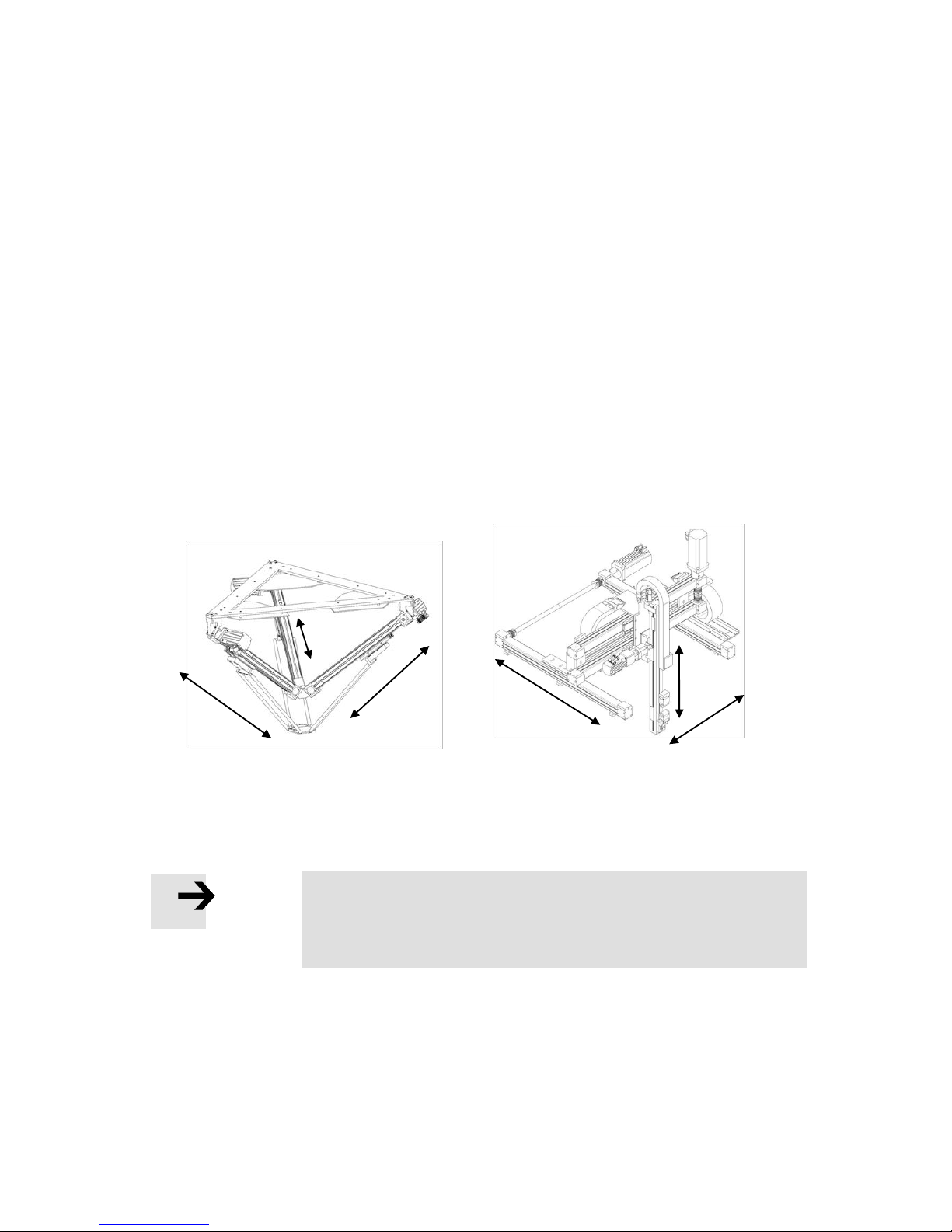
11. Supported kinematic systems
Festo GDCP-CMXR-C2-SY-EN 1205b 59
11. Supported kinematic systems
The CMXR multi-axis control system has internal kinematics models. These models
describe the type of kinematics systems as well as their axes in the arrangement, position
and form. All the kinematics models that are supported by the CMXR system are described
below. The maximum number of axes in a kinematics system is limited to six.
11.1 Configuration of kinematics
Kinematics essentially comprise basic axes and orientation axes (wrist axes). Their
significance and function are described below. Auxiliary axes that interpolate together to
the kinematics' target position are still an option for these kinematics axes.
11.1.1 Basic axes
The axes A1, A2 and A3 normally form the three axes that cover the up to three translation
axes X, Y and Z in the Cartesian system. These axes can approach positions in a Cartesian
space. If a tool is attached to the basic axes, then its orientation is coupled to the position
of the basic axes and cannot be affected.
The illustrations show the Festo kinematics systems EXTP and three-dimensional gantry.
The axes A1, A2 and A3 form the basic axes of the kinematics systems.
Note
All basic axes are electric axes that are controlled via the CMXR
multi-axis control system. The use of pneumatic axes as basic axes
is not possible.
A1
A2
A3
A1
A3
A2
Page 60
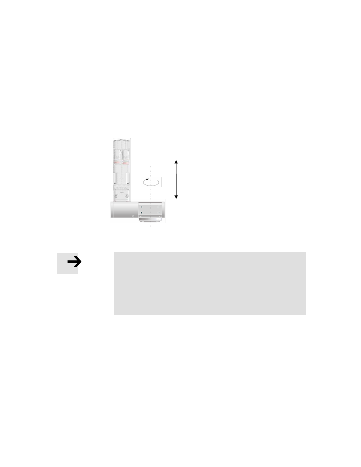
11. Supported kinematic systems
60 Festo GDCP-CMXR-C2-SY-EN 1205b
11.1.2 Orientation axes (wrist axes)
The orientation axes, also called wrist axes, are attached to one end of the basic axes.
These axes are of a rotary design. A maximum of one orientation axis is possible, and this
forms another degree of freedom along with the basic axes' three degrees of freedom.
Together with the basic axes, this results in a maximum four degrees of freedom in a
kinematics system.
At the end of the orientation axes there is a tool flange upon which the tool is mounted.
Thus the tool can be oriented in the available space by using the orientation axes, in a
similar fashion to a human hand. This is where the notion wrist axis is derived.
Note
Should an orientation change be required on the path, then the
orientation axis must be of electric design so that it can interpolate
on the path.
Pneumatic rotary and semi-rotational axes can also be used as
orientation axes, but with static orientation that has to be set via
the tool data.
11.1.3 Adjustment of orientation axes
When the orientation axis is rotated, the orientation of the tool follows simultaneously.
This means the orientation of the tool coordinate system, whose origin is on the TCP,
changes analogously with the orientation of the orientation axis.
The orientation axis is rotated by +45 in the following example. The tool coordinate system
(Tx and Ty) is carried along with it analogously. The global coordinate system is not
affected by this.
-
Z-axis
+
Example: Electrical module with one degree of freedom
Page 61
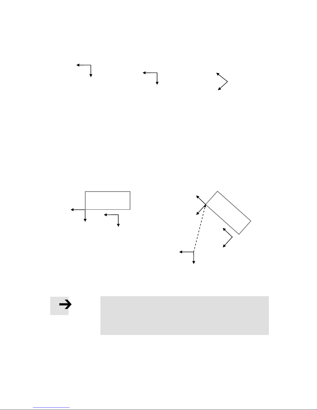
11. Supported kinematic systems
Festo GDCP-CMXR-C2-SY-EN 1205b 61
If a reference system is activated by programming in FTL (Festo Teach Language), this has
an additive impact on the global coordinate system. If a rotation that can be covered by the
kinematics' degree of freedom (e.g. rotation around the Z-axis) is generated in the
reference system, then the orientation axis is automatically adjusted. In the following
example, the right contour is offset and rotated using a reference system. Since the
rotation can be executed with the orientation axis, then the axis will be adjusted. Thus the
tool is guided to the contour (in the same way it would be without a rotation) almost at
once.
Note
If a contour is oriented in the available space by a reference
system, then the tool is automatically guided on the contour with
the aid of an orientation axis. The prerequisite is that the required
degrees of freedom are covered by the orientation axis.
Ty+
Tx+
Y+
X+
Contour without offset
Contour with offset and rotation
by the reference system
Y+
X+
Y+
X+
Ty+
Tx+
Ty+
Tx+
Y+
X+
Global coordinate system
Orientation axis
= 0 degrees
Ty+
Tx+
Orientation axis
= 45 degrees
Page 62
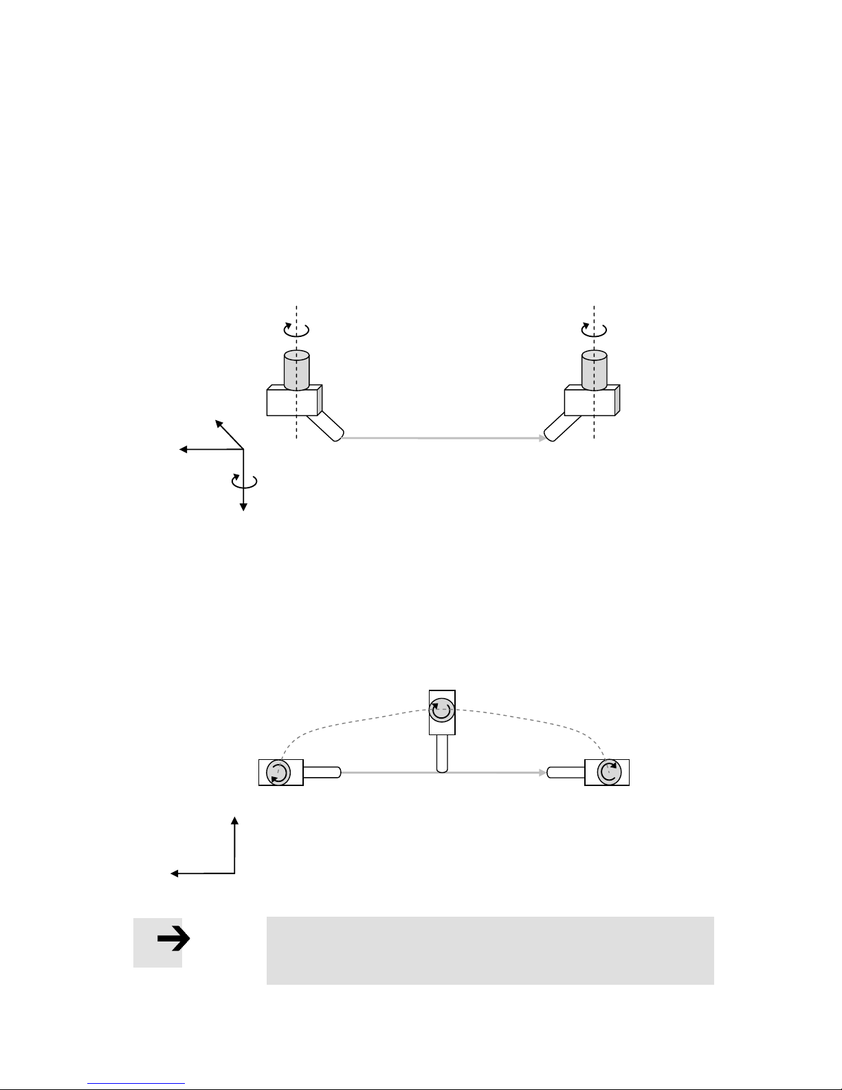
11. Supported kinematic systems
62 Festo GDCP-CMXR-C2-SY-EN 1205b
11.1.4 Interpolation of orientation axes
All basic and wrist axes are axes for the kinematics. The movements of these kinematics
axes are calculated by the internal kinematics model, the coordinate transformation. With
Cartesian movements, the Cartesian position and the specified orientation are also taken
into account. In the process, it is quite possible that several axes can move in just one
position command. This is dependent on the position command as well as the type of
kinematics used.
In the example below, an elbowed tool is attached to an orientation axis.
This tool is guided on the path, whereby the orientation is turned by 180 degrees.
The illustration below shows the top view of the movement. This tool point is guided on
the path, whereby the orientation (rotation by 180 degrees) follows simultaneously. The
Cartesian axes X, Y and Z carry out a so-called compensating movement in overlapping
fashion to the path movement. This is necessary so that position, orientation and tool
adapt to the path.
Note
Axes movements that follow the orientation change are also known
as a compensating movements.
Path of the tool flange
Path of the tool
X+
Y+
+
Orientation axis
+
X+
A+
Y+
Z+
Page 63
11. Supported kinematic systems
Festo GDCP-CMXR-C2-SY-EN 1205b 63
Note
Because the orientation axes, e.g. produced by reference systems,
automatically rotate as a result of the adjustment, you have to
check that all application lines (cables, hoses) are not damaged.
During the interpolation of the orientation axis, you must make sure that it responds
differently when a Cartesian or axis position is specified within a movement. If using a
Cartesian position, the target position is approached by the shortest route so that
movements are kept to a minimum. If a position is specified in axis coordinates, then the
orientation axis will always cover the programmed route.
Caution: Danger of collision
When integrating the orientation axes into the movement, a
commissioning procedure must be implemented to ensure that a
rotation of the orientation axis moves in the required direction. We
recommend you teach and test the orientation movements via the
handheld terminal.
Page 64
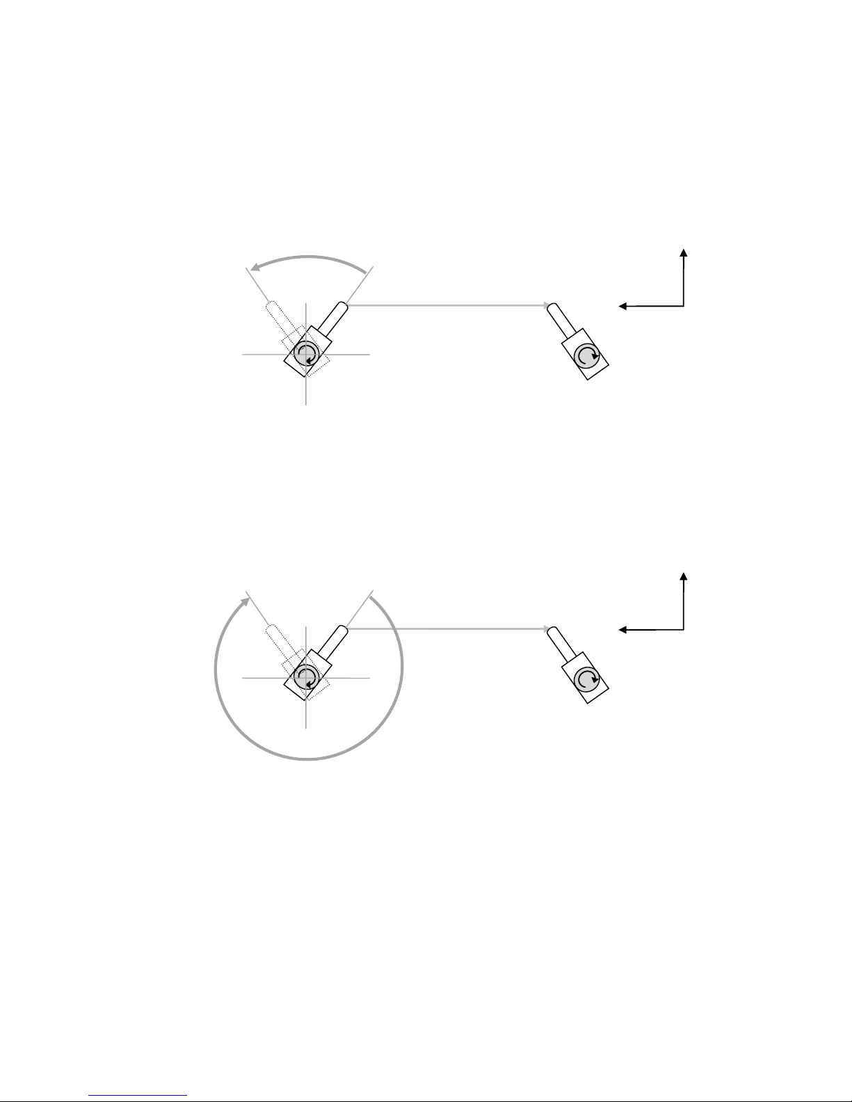
11. Supported kinematic systems
64 Festo GDCP-CMXR-C2-SY-EN 1205b
In the example below, the orientation axis is at the 40 degree position. If a movement is
now programmed with a Cartesian position (position of the type CARTPOS), in which the
orientation axis has to rotate to 320 degrees, then it will carry out the shortest route, i.e. it
effectively moves 80 degrees in this example.
If now an axis position (position of the type AXISPOS) is specified during the movement
instead of a Cartesian position, then the orientation axis rotates from the 40 degree
position to the 320 degree position, while having the sign taken into account. In this
example, the orientation axis effectively travels 280 degrees.
Path of the tool
X+
Y+
0°
90°
180°
270°
Path of the orientation axis when
an axis position is specified
40°
320°
Path of the tool
X+
Y+
0°
90°
180°
270°
Path of the orientation axis when
a Cartesian position is specified
40°
320°
Page 65
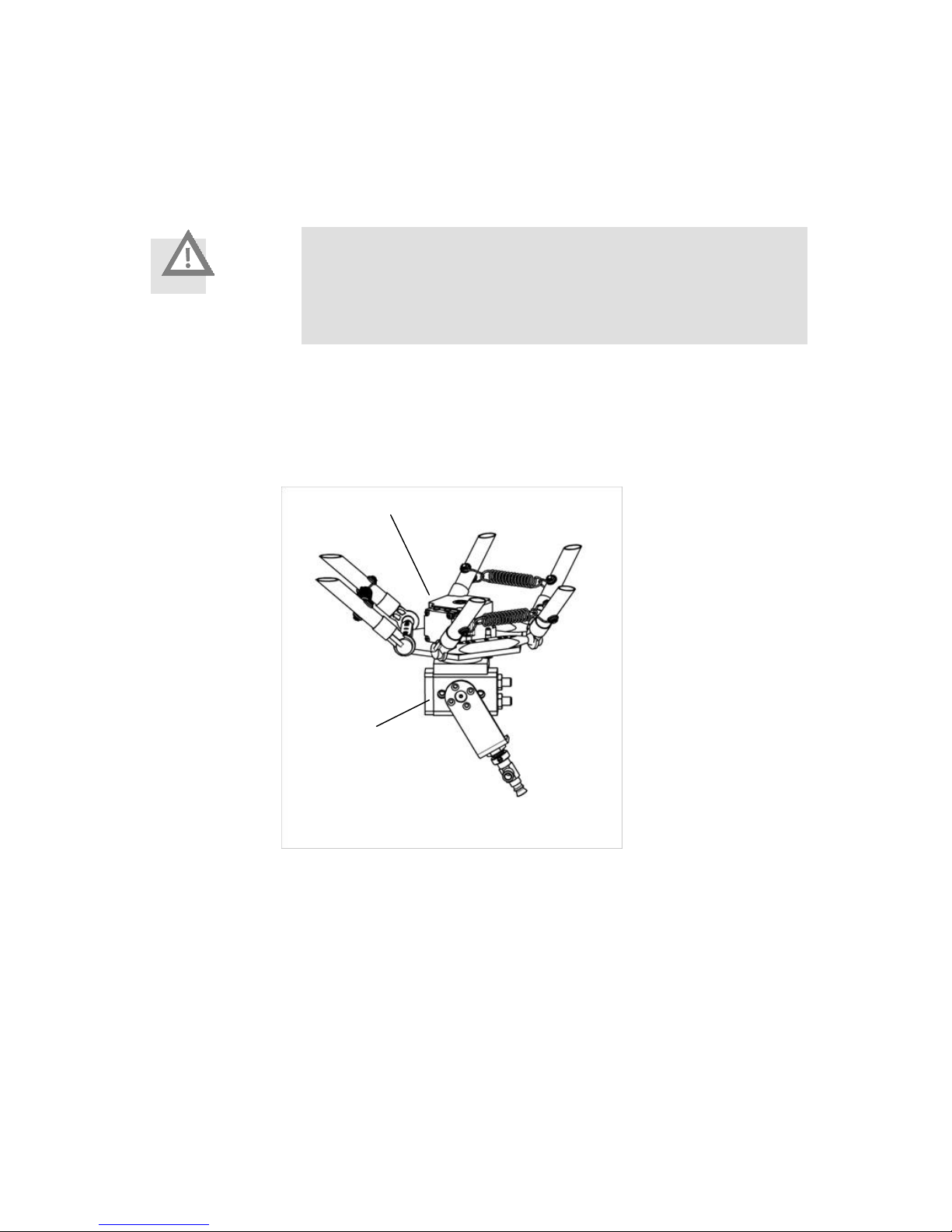
11. Supported kinematic systems
Festo GDCP-CMXR-C2-SY-EN 1205b 65
11.1.5 Electric and pneumatic wrist axes
A pneumatic semi-rotational axis is not regarded as a wrist axis, because it cannot be
moved in an interpolating fashion. It must therefore be taken into account within the tool
definition.
Caution
When using pneumatic axes, always take into consideration the
correct tool definitions. Incorrect tool definitions or tool definitions
not taken into consideration can cause collisions and material
damage.
The illustration below shows an application for a pneumatic semi-rotational axis behind an
electric wrist axis. Shown here is an extract of the tripod kinematics with an electric
orientation axis that has a pneumatic DRQD semi-rotational axis (with a vacuum gripper)
mounted to it.
11.1.6 Auxiliary axes
In contrast to basic and wrist axes, auxiliary axes do not belong to the kinematics model
and are not taken into account by the kinematics model of the coordinate transformation.
Auxiliary axes are jointly interpolated by the CMXR multi-axis control system for the
Cartesian movement of the basic and wrist axes in the form of a point-to-point movement.
Pneumatic DRQD rotary
drive
Electric orientation axis
Page 66
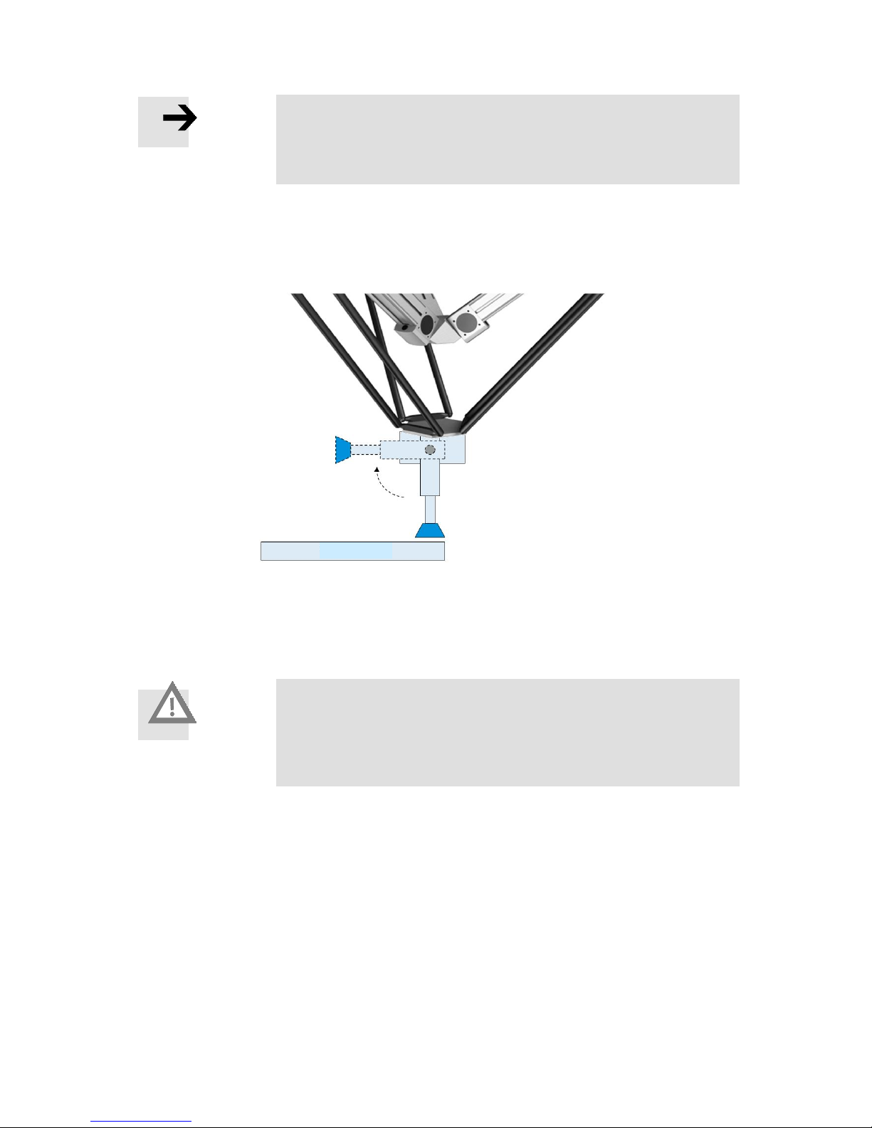
11. Supported kinematic systems
66 Festo GDCP-CMXR-C2-SY-EN 1205b
Note
Auxiliary axes are always interpolated together for the Cartesian
movement. A separate, asynchronous movement of auxiliary axes
for Cartesian movement of the kinematics is not possible.
The following example shows the use of an electric auxiliary axis in a tripod kinematics
system. The auxiliary axis is also used as a rotational axis on the tool flange, since this
configuration is not included in the tripod kinematics model.
The graphic shows a positional change of the rotational auxiliary axis. Because this axis
cannot carry out a Cartesian movement, the other axes do not carry out a compensating
movement. When auxiliary axes are used, the movements must always be checked to
make sure that a collision does not occur.
Caution
If auxiliary axes are used, there is a danger of collision during
movements, because the tool (TCP) under certain circumstances is
not guided on the path of the kinematics axes. It is absolutely
essential that the movement is commissioned.
11.1.7 Programming the manual and auxiliary axes
Manual and auxiliary axes are moved via a PTP movement on the basis of the internal
interpolation. This interpolation type needs a dynamic specification, as is the case for PTP
movements. This means a path's programmed Cartesian dynamics has no effect on the
dynamics of the manual and auxiliary axes.
To influence the dynamics of the manual and auxiliary axes, the percentage dynamic
specifications, as in a PTP, are also needed for the Cartesian dynamics.
Workpiece
Page 67

11. Supported kinematic systems
Festo GDCP-CMXR-C2-SY-EN 1205b 67
Note
Within a Cartesian movement, dynamic specifications for PTP
movements are also required for auxiliary and wrist axes. These
must be specified as a percentage with the associated FTL
commands.
Please refer to the programming manual for more information.
11.1.8 Designation of axis sequence for kinematics
Basic and wrist axes for kinematics describe a sequence of axes. To simplify this sequence
in its representation, letters are also used to describe the axis chain. Using this type of
identification as a basis, the kind of axis used is also specified, whether it be a linear or
rotational axis.
L means linear axis
R means rotational axis
The identifier is configured as followed:
<String for basic axes> - <String for wrist axes>
Examples:
LL-R Kinematics with two linear basic axes and one rotational wrist axis
LLL-RR Kinematics with three linear basic axes and two rotational wrist axes
11.2 Cartesian linear gantry
A linear gantry is understood as a Cartesian kinematics system with two basic axes that
stand perpendicular to one another and thus form a Cartesian system. These axes are
arranged in a Cartesian fashion in a X-Z- or Y-Z sequence. The vertical axis always forms
the Cartesian Z-axis. As an option, an orientation axis can be attached to the tool flange.
Page 68
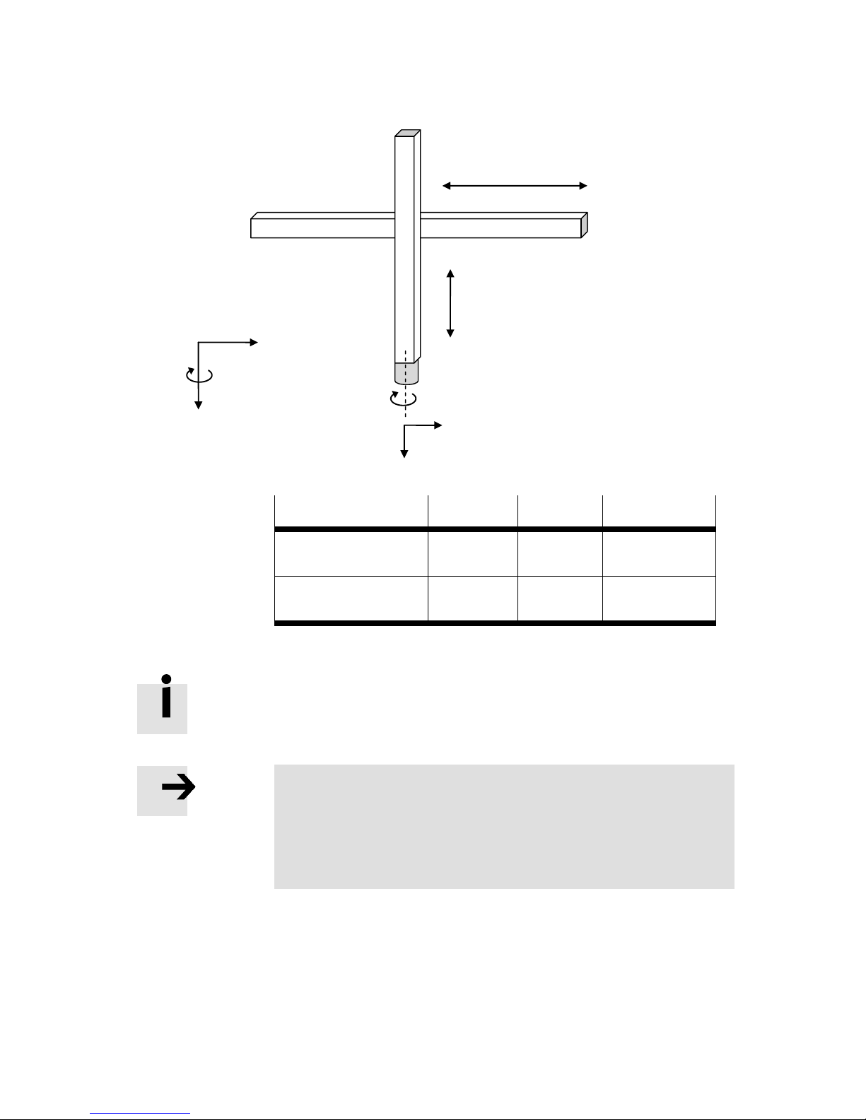
11. Supported kinematic systems
68 Festo GDCP-CMXR-C2-SY-EN 1205b
Kinematics
Number of
basic axes
Number of
wrist axes
Axis sequence
Linear gantry without
axis of rotation
2 0 LL
Linear gantry with
axis of rotation
2 1 LL-R
Table 11.1 Configurations of linear gantry
The arrangement of the Cartesian axes in X-Z or Y-Z design is set via
the Festo Configuration Tool (FCT).
Note
The zero point of the global coordinate system is defined by the
zero point of axes 1 and 2. The zero position and the direction of
rotation of axis 3 must be parameterised such that the tool coordinate system (Tx or Ty, Tz) is congruent with the base coordinate
system for the kinematics.
The reduced kinematics only allows limited interpolating orientation axes, because the
third degree of freedom of the basic axes is missing; this is to induce the tool to make
compensating movements in the available space. Cartesian movements can thus only be
carried out in the direction of the available basic axes, axis 1 and axis 2.
- Axis 1 +
-
Axis 2
Axis 3
X+ or Y+
Z+
A+
+
Tz+
Tx+ or Ty+
Page 69
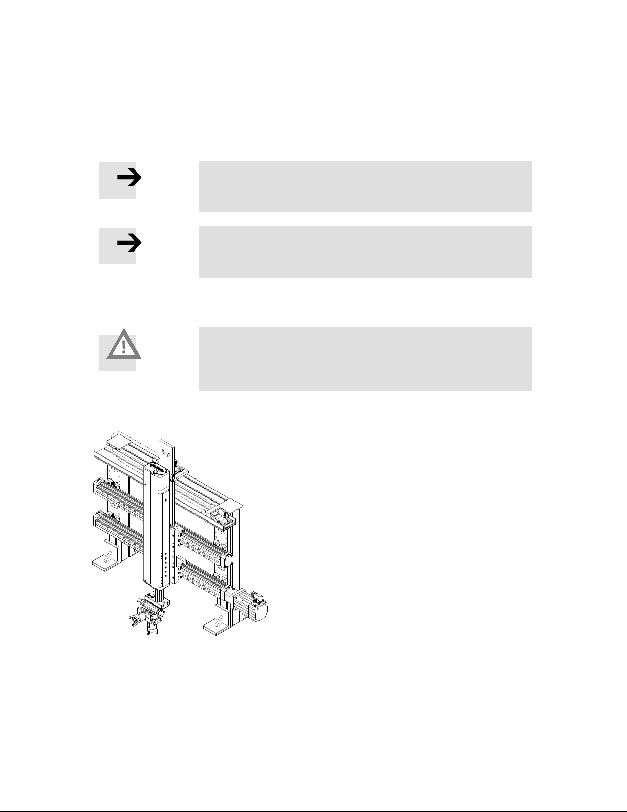
11. Supported kinematic systems
Festo GDCP-CMXR-C2-SY-EN 1205b 69
Example
The kinematics system has an orientation axis (axis 3) upon which a tool, whose TCP is
defined in the available space (not vertical), is mounted. A Cartesian rotation of axis 3
around the TCP is not possible due to the missing degree of freedom in the basic axes. This
type of rotation has to be moved with PTP interpolation, in which the TCP is insignificant.
Note
With a linear gantry, only limited interpolating wrist axes are
feasible due to the missing degree of freedom.
Note
Positioning commands to a non-available degree of freedom are
not possible and will lead to an error.
The repositioning of the linear gantry is carried out via a PTP movement.
Caution
Repositioning is carried out via a PTP interpolation. In doing so,
make sure that no obstacles stand in the way of the movement
during the repositioning.
The illustration below shows a Festo linear gantry:
11.3 Cartesian planar surface gantry
A planar surface gantry is a Cartesian kinematics system that comprises two basic axes
which stand perpendicular to one another. It thus has two translatory degrees of freedom.
These axes are laid out as X and Y and cover the X-Y level. An electric Z-axis that jointly
interpolates is not present. The movements in the Z-direction can, for example, be
Page 70
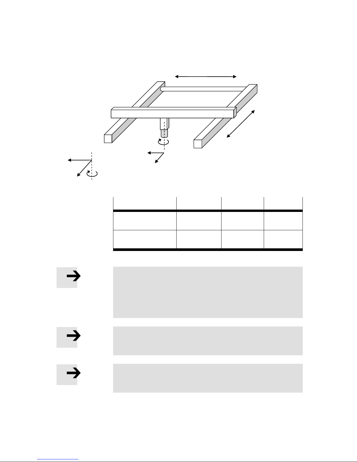
11. Supported kinematic systems
70 Festo GDCP-CMXR-C2-SY-EN 1205b
implemented through a pneumatic drive. As an option, an orientation axis can be attached
to the tool flange in this kinematics system.
Kinematics
Number of basic
axes
Number of wrist
axes
Axis
sequence
Planar surface gantry
without axis of rotation
2
0
LL
Planar surface gantry with
axis of rotation
2
1
LL-R
Table 11.2 Configurations of planar surface gantry
Note
The zero point of the global coordinate system is defined by the
zero point of axes 1 and 2. The zero position and the direction of
rotation of axis 3 must be parameterised such that the tool coordinate system (Tx or Ty, Tz) is congruent with the base coordinate
system for the kinematics.
Note
With a planar surface gantry, only limited interpolating wrist axes
are feasible due to the missing degree of freedom.
Note
Positioning commands to a non-available degree of freedom are
not possible and will lead to an error.
The repositioning of the planar surface gantry is carried out via a PTP movement.
+ Axis 2 -
Axis 3
+
Tx+
Ty+
Axis 1
- + Y+
A+
X+
Page 71
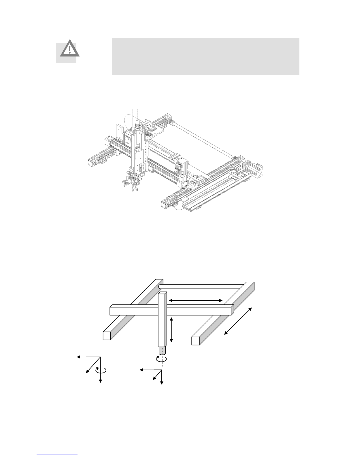
11. Supported kinematic systems
Festo GDCP-CMXR-C2-SY-EN 1205b 71
Caution
Repositioning is carried out via a PTP interpolation. In doing so,
make sure that no obstacles stand in the way of the movement
during the repositioning.
The illustration below shows a Festo planar surface gantry with a pneumatic Z-axis:
11.4 Cartesian three-dimensional gantry
A three-dimensional gantry is a Cartesian kinematics system that can move in the available space with its three basic axes. It has the basic axes X, Y and Z, which stand perpendicular to one another. As an option, an orientation axis can be attached to the tool flange
in this kinematics system.
+ Axis 2 -
Axis 4
+
Tx+
Ty+
Axis 1
-
+
Tz+
Y+
A+
X+
Z+
Axis 3
+
-
-
Page 72
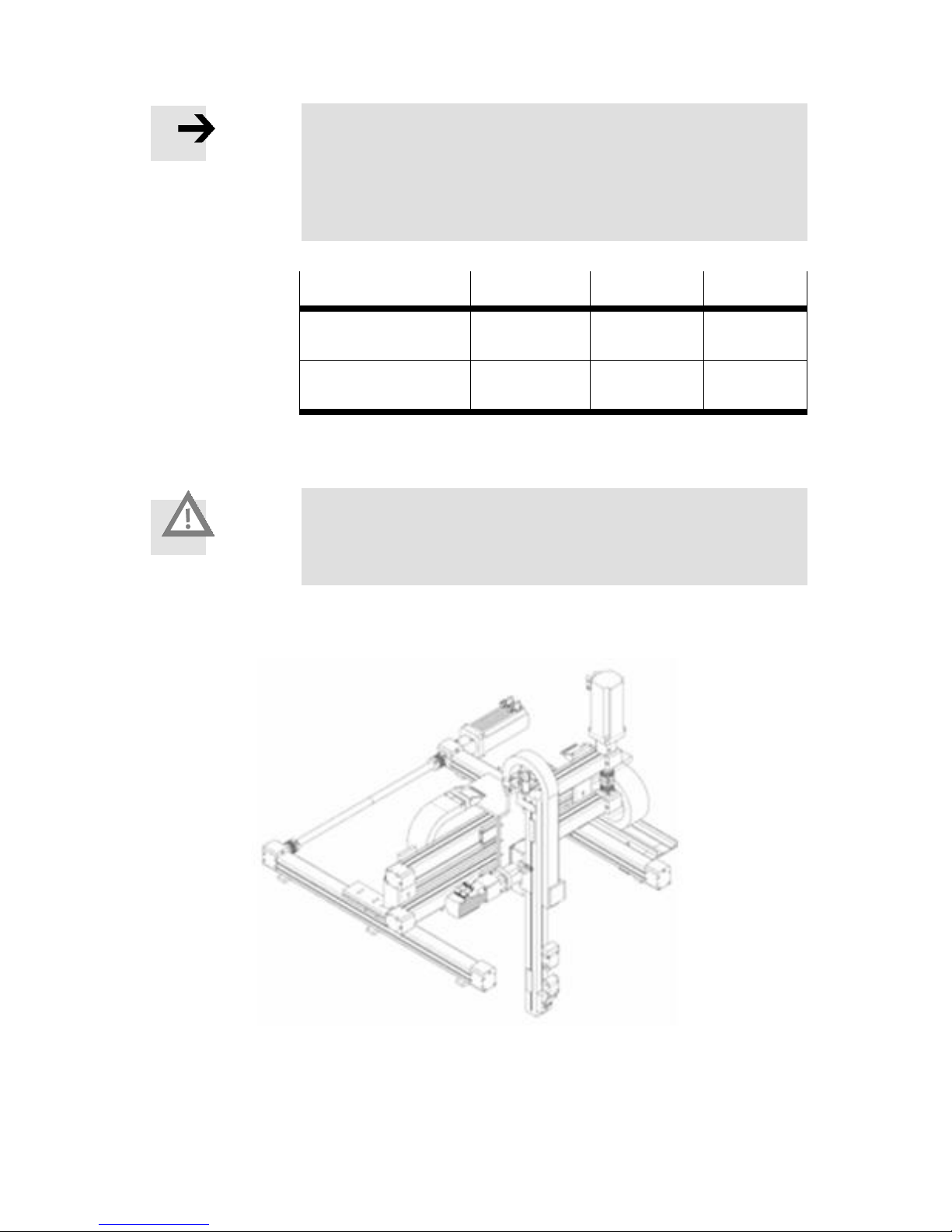
11. Supported kinematic systems
72 Festo GDCP-CMXR-C2-SY-EN 1205b
Note
The zero point of the global coordinate system is defined by the
zero point of axes 1, 2 and 3. The zero position and the direction of
rotation of axis 4 must be parameterised such that the tool coordinate system (Tx or Ty, Tz) is congruent with the base coordinate
system for the kinematics.
Kinematics
Number of basic
axes
Number of wrist
axes
Axis
sequence
Three-dimensional gantry
without axis of rotation
3
0
LLL
Three-dimensional gantry
with axis of rotation
3
1
LLL-R
Table 11.3 Configurations of three-dimensional gantry
The repositioning of the three-dimensional gantry is carried out via a PTP movement.
Caution
Repositioning is carried out via a PTP interpolation. In doing so,
make sure that no obstacles stand in the way of the movement
during the repositioning.
The illustration below shows a Festo three-dimensional gantry:
Page 73
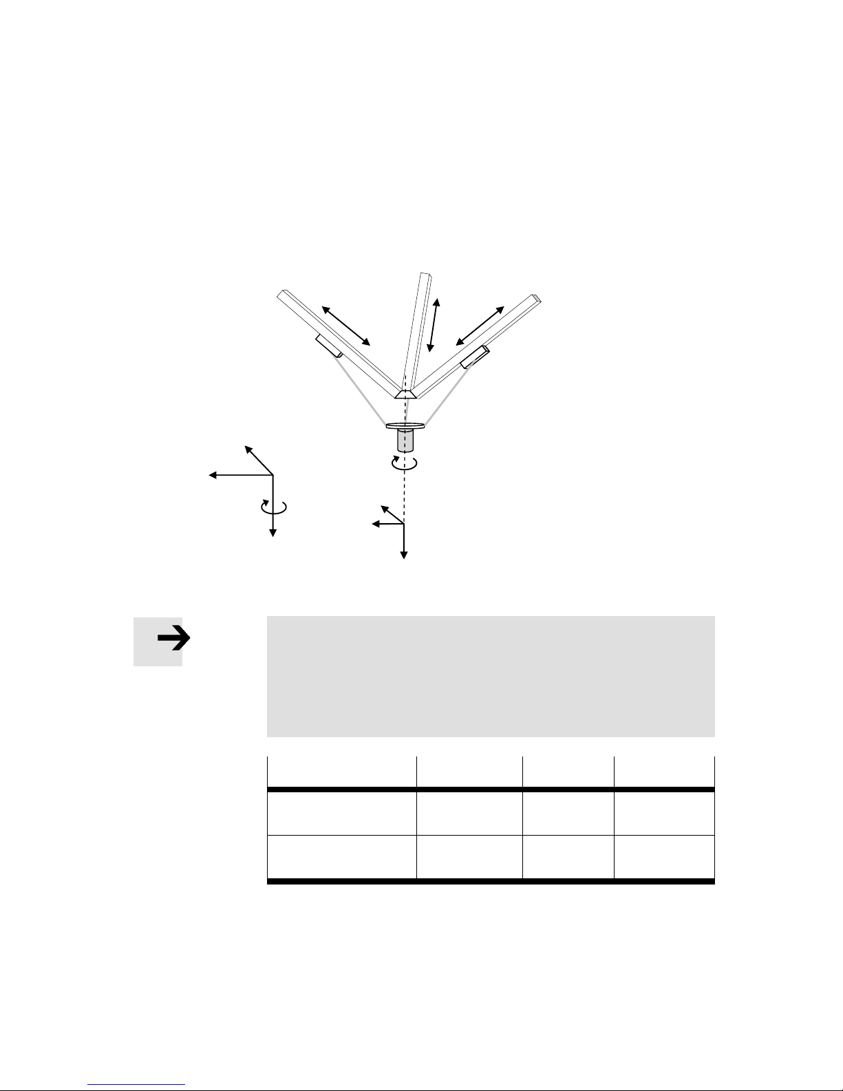
11. Supported kinematic systems
Festo GDCP-CMXR-C2-SY-EN 1205b 73
11.5 EXPT kinematics system
The EXPT kinematics system is a parallel rod kinematics system. In contrast to the
Cartesian kinematics system, the arrangement of the axes is not perpendicular to one
another and does not form a Cartesian space. This kinematics system has 3 degrees of
freedom. Optionally, an orientation axis (axis 4) can be mounted on the tool flange.
Note
The zero point of the global coordinate system is defined by the
zero point of axes 1, 2 and 3. The zero position and the direction of
rotation of axis 4 must be parameterised such that the tool coordinate system (Tx or Ty, Tz) is congruent with the base coordinate
system for the kinematics.
Kinematics
Number of basic
axes
Number of
wrist axes
Axis
sequence
Tripod without axis of
rotation
3
0
LLL
Tripod with axis of
rotation
3
1
LLL-R
Table 11.4 Configuration of tripod kinematics
The position of the Cartesian coordinate system is determined by axis 1 for the tripod. If
axis 1 is projected onto the horizontal level, then the axis vector describes the direction of
the Cartesian X-axis. The positive direction of the Cartesian X-axis is determined by the
negative direction of axis 1.
Axis 4
+
Ty+
Tx+
Tz+
Axis 1
- + + + -
Axis 3
Axis 2
-
X+
A+
Y+
Z+
Page 74
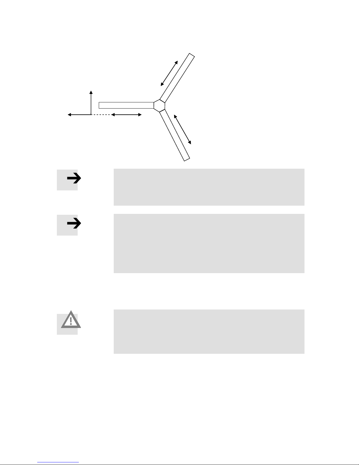
11. Supported kinematic systems
74 Festo GDCP-CMXR-C2-SY-EN 1205b
Note
The alignment of the global coordinate system is defined by the
position of axis 1. If axis 1 is projected onto the horizontal level,
then this is the direction of the Cartesian X-axis.
Note
Should an alignment of the Cartesian axes to another reference
system, e.g. a conveyor unit, be required when assembling the
tripod, then this must be carried out by aligning the tripod via axis
1. The precise alignment is carried out by offsetting the global
coordinate system. This is defined via the Festo Configuration Tool
(FCT).
Owing to the design of the kinematics, the repositioning for the tripod is carried out with
Cartesian linear interpolation.
Caution
Repositioning is carried out via Cartesian linear interpolation.
In doing so, make sure that no obstacles stand in the way of the
movement during the repositioning. If a tool is defined, then it is
moved on the path to the interruption point.
11.5.1 Origin of the tool coordinate system
The tool coordinate system is, with its axis directions for the zero position of the
orientation axes, congruent with the tripod's base coordinate system. The zero point of the
tool coordinate system is placed centrally at the level of the flange plate.
Axis 3
-
+
+ + -
-
Axis 1
Axis 2
X+
Y+
Page 75
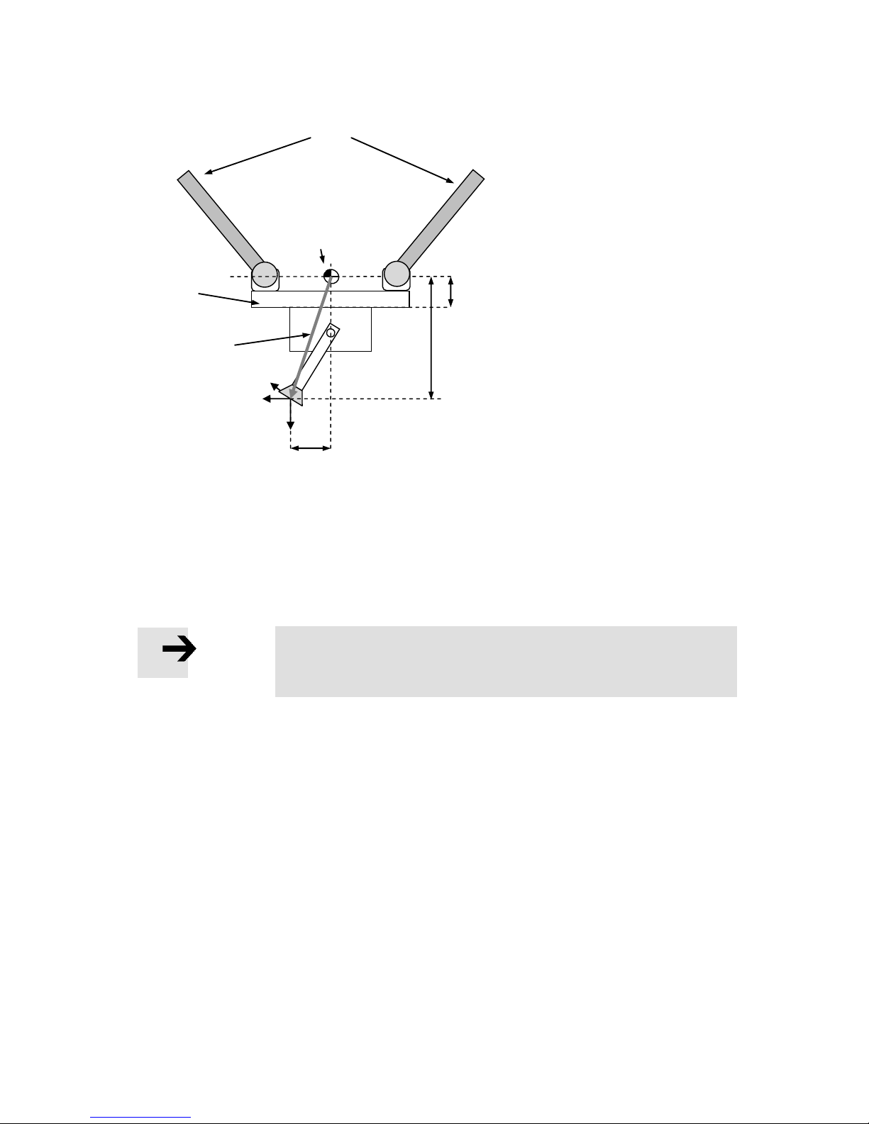
11. Supported kinematic systems
Festo GDCP-CMXR-C2-SY-EN 1205b 75
The origin of the TCP vector is in the original zero point for the tool coordinate system on
the tool flange. The TCP vector shifts the tool coordinate system according to its definition.
When defining a TCP vector for a tool mounted on the flange plate, you must make sure
that the vector has to be specified from the origin of the tool coordinate system on the tool
flange. The offset to the flange plate must be taken into consideration along with any other
constructions.
Note
When defining the TCP vector, the offset dimension to the flange
plate must be taken into consideration.
Rods
Flange plate
Offset in Z+ to
flange
Origin of the tool
coordinate system
Ty+
Tx+
Tz+
TCP vector X
TCP vector Z
TCP vector
Page 76
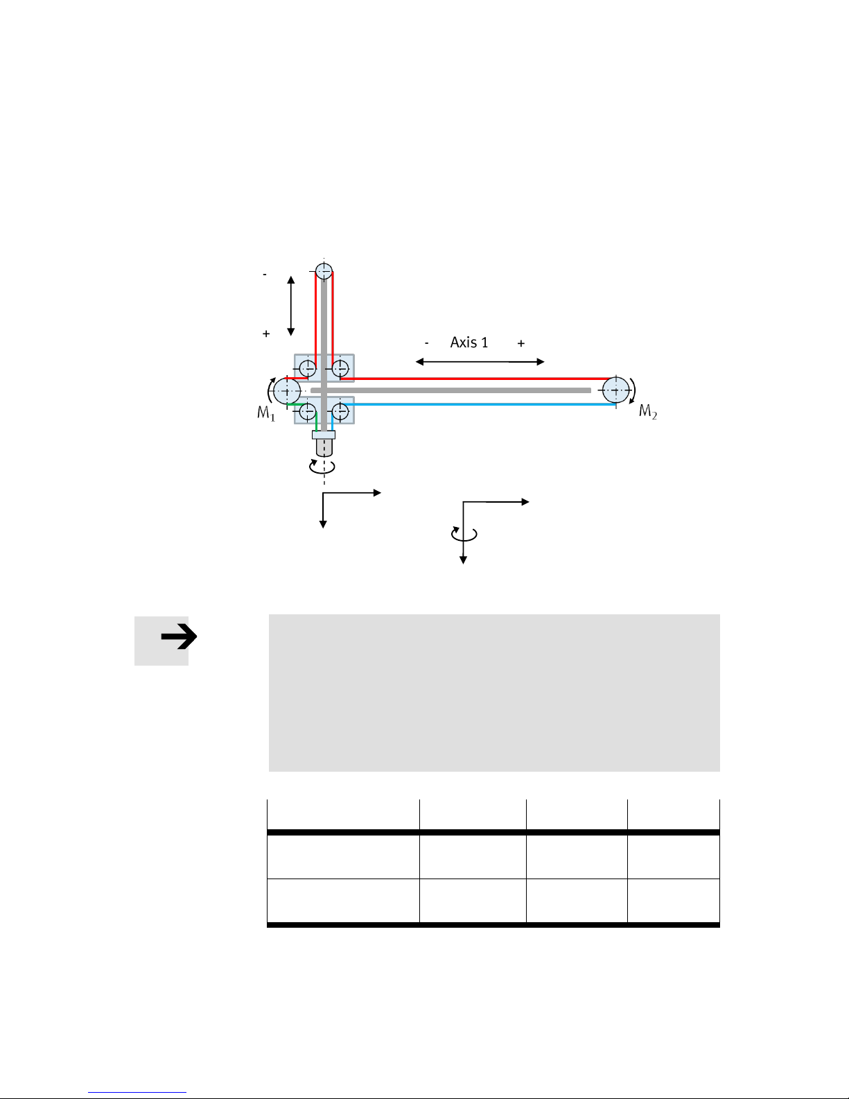
11. Supported kinematic systems
76 Festo GDCP-CMXR-C2-SY-EN 1205b
11.6 T-gantry
A T-gantry is a kinematics system with a rotating toothed belt and stationary motors. It has
2 basic axes, which are perpendicular to each other. Optionally, an orientation axis can be
attached to the tool flange in this kinematics system.
Note
The zero point of the world coordinate system is defined by the
zero point of axes 1 and 2. To set up the zero point, please observe
the kinematics manual.
The zero position and the direction of rotation of axis 3 must be
parameterised in such a way that the tool coordinate system (Ty,
Tz) is the same as the base coordinate system of the kinematics
system.
Kinematics system
Number of basic
axes
Number of
manual axes
Axis
sequence
T-gantry without axis of
rotation
2 0 LL
T-gantry with axis of
rotation
2 1 LL-R
Table 11.5 T-gantry configurations
- Axis 1 +
Axis 3
+
Ty+
Axis 2
Tz+
Y+
A+
Z+
+ - Front view
Page 77
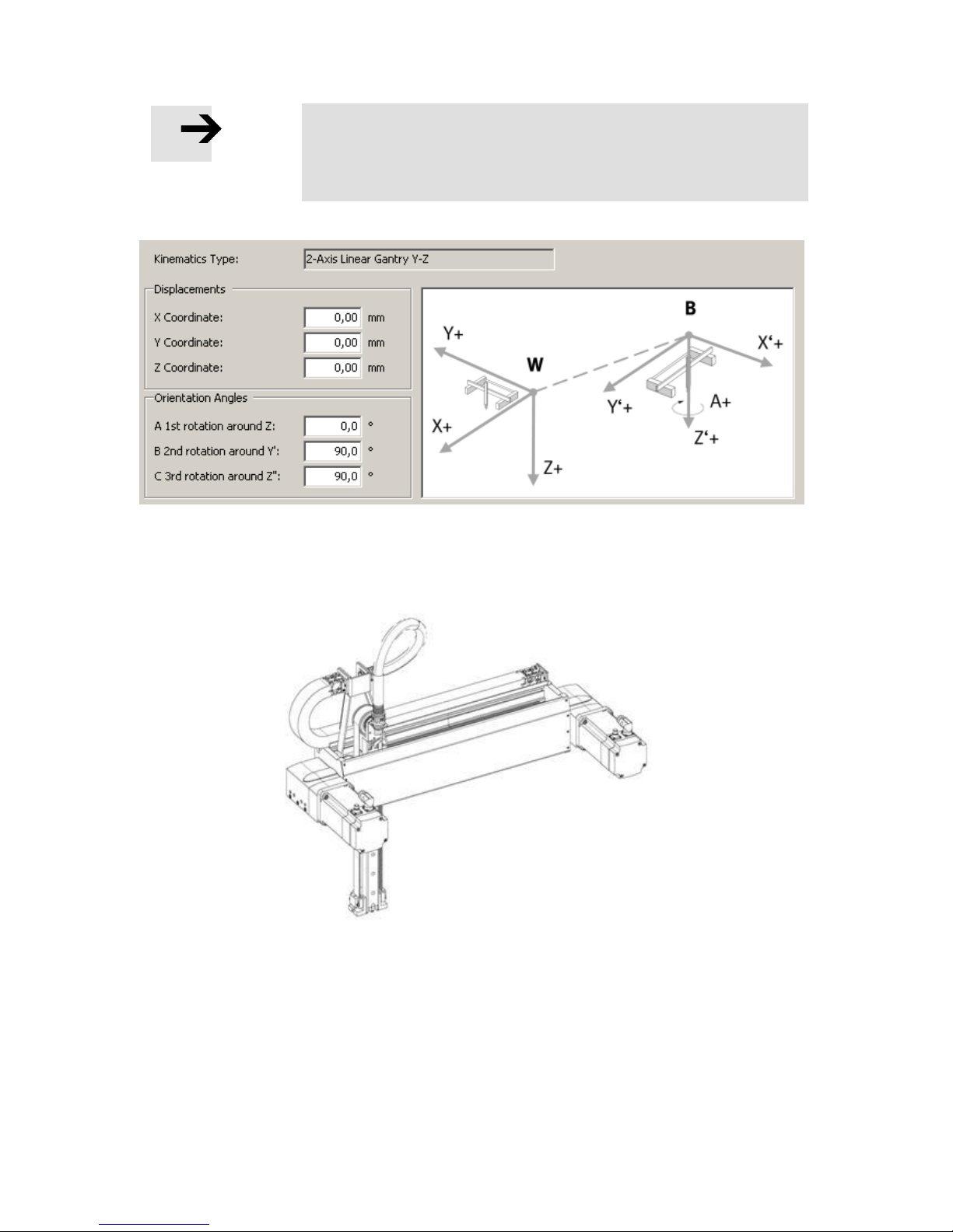
11. Supported kinematic systems
Festo GDCP-CMXR-C2-SY-EN 1205b 77
Note
The T-gantry cannot be selected directly as a kinematics type in the
FCT plug-in. A Cartesian linear gantry (Y-Z) must be selected and
the base in B and C in each case twisted by 90 degrees.
The following illustration shows a Festo T-gantry:
Page 78
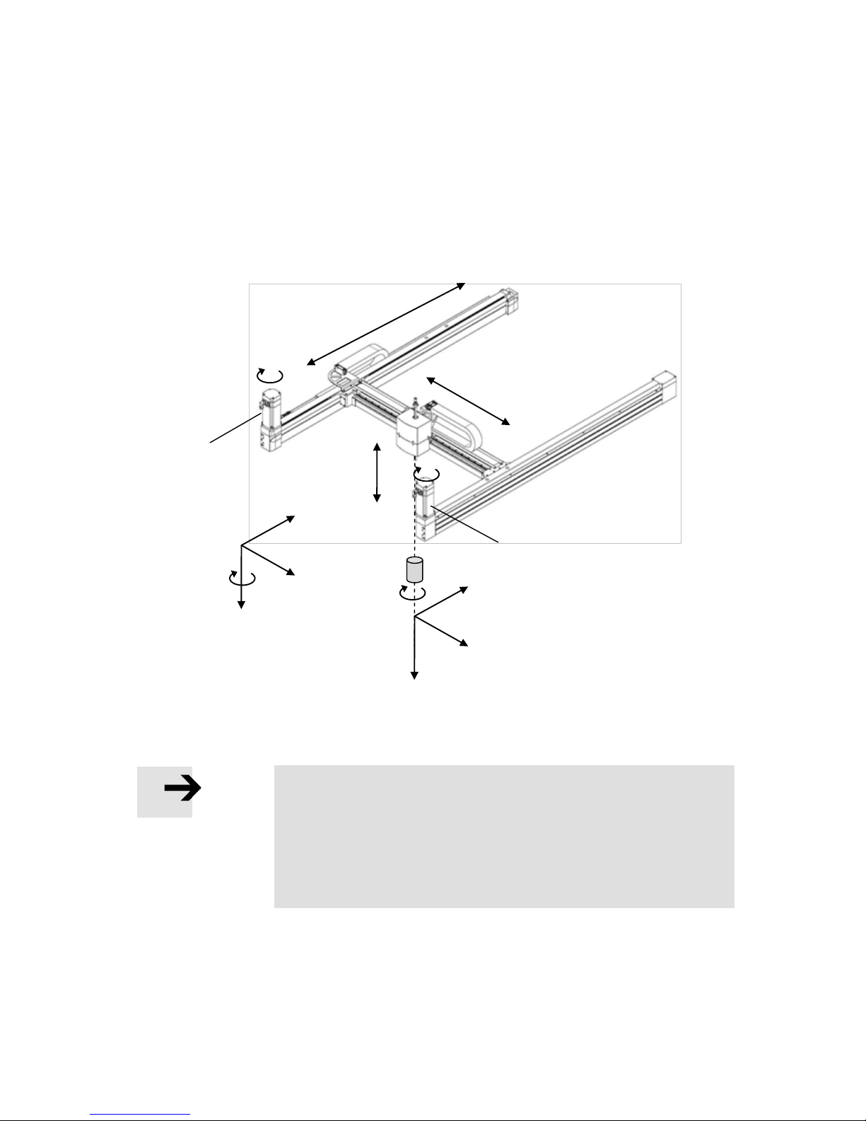
11. Supported kinematic systems
78 Festo GDCP-CMXR-C2-SY-EN 1205b
11.1 H-gantry
An H-gantry is a kinematics system with a rotating toothed belt and stationary motors. It
has optionally 2 or 3 basic axes, which are perpendicular to each other. Optionally, an
orientation axis can be attached to the tool flange in this kinematics system.
Illustration of H-gantry with 3 basic axes:
Note
The zero point of the world coordinate system is defined by the
zero point of axes 1, 2 and 3. To set up the zero point, please
observe the kinematics manual.
The zero position and the direction of rotation of axis 4 must be
parameterised such that the tool coordinate system (Tx or Ty, Tz) is
the same as the base coordinate system for the kinematics system.
Y+
A+
Z+
X+
Ty+
Tz+
Tx+
Axis 4
+
Axis 1
- + Axis 2
+ - Axis 3
+ - Motor 2
Motor 1
M+
M+
Page 79
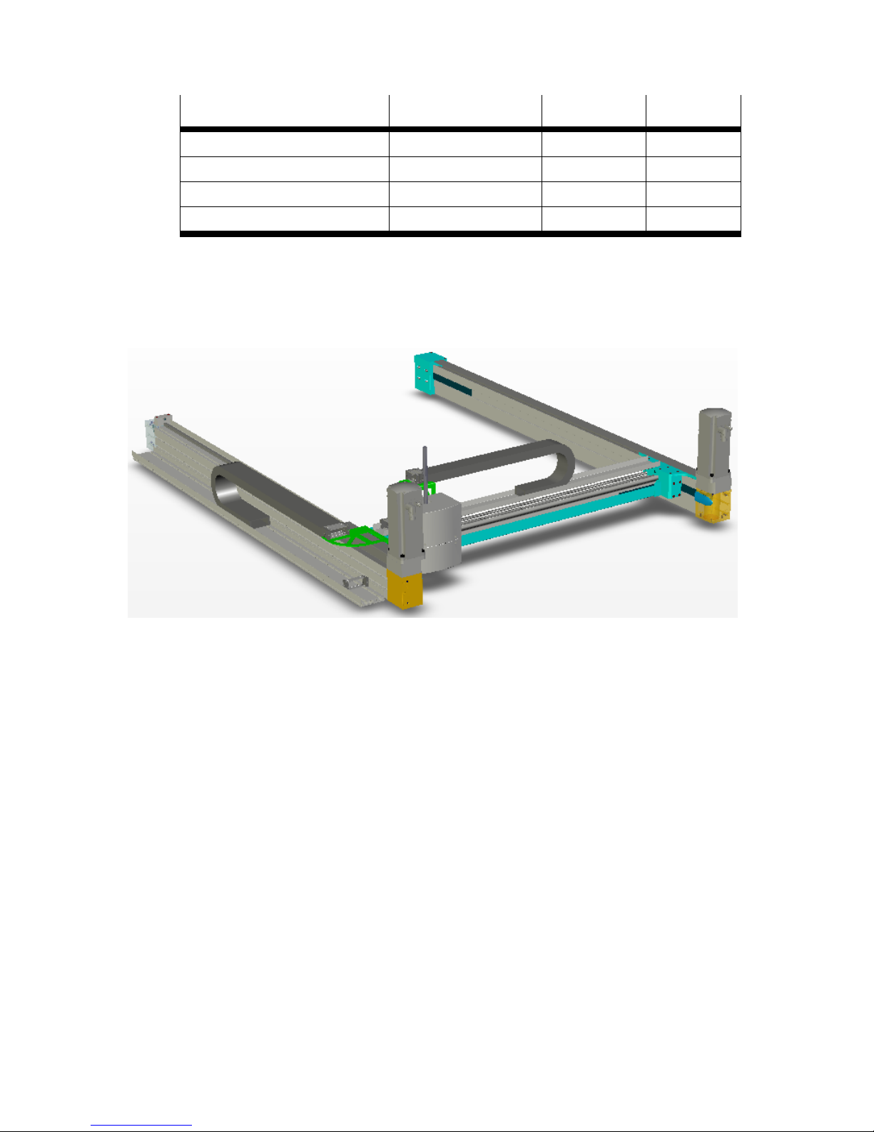
11. Supported kinematic systems
Festo GDCP-CMXR-C2-SY-EN 1205b 79
Kinematics system
Number of basic axes
Number of
manual axes
Axis
sequence
H-gantry 2D without axis of rotation
2 0 LL
H-gantry 2D with axis of rotation
2 1 LL-R
H-gantry 3D without axis of rotation
3 0 LLL
H-gantry 3D with axis of rotation
3 1 LLL-R
Table 11.6 H-gantry configurations
The following illustration shows a Festo H-gantry:
Page 80
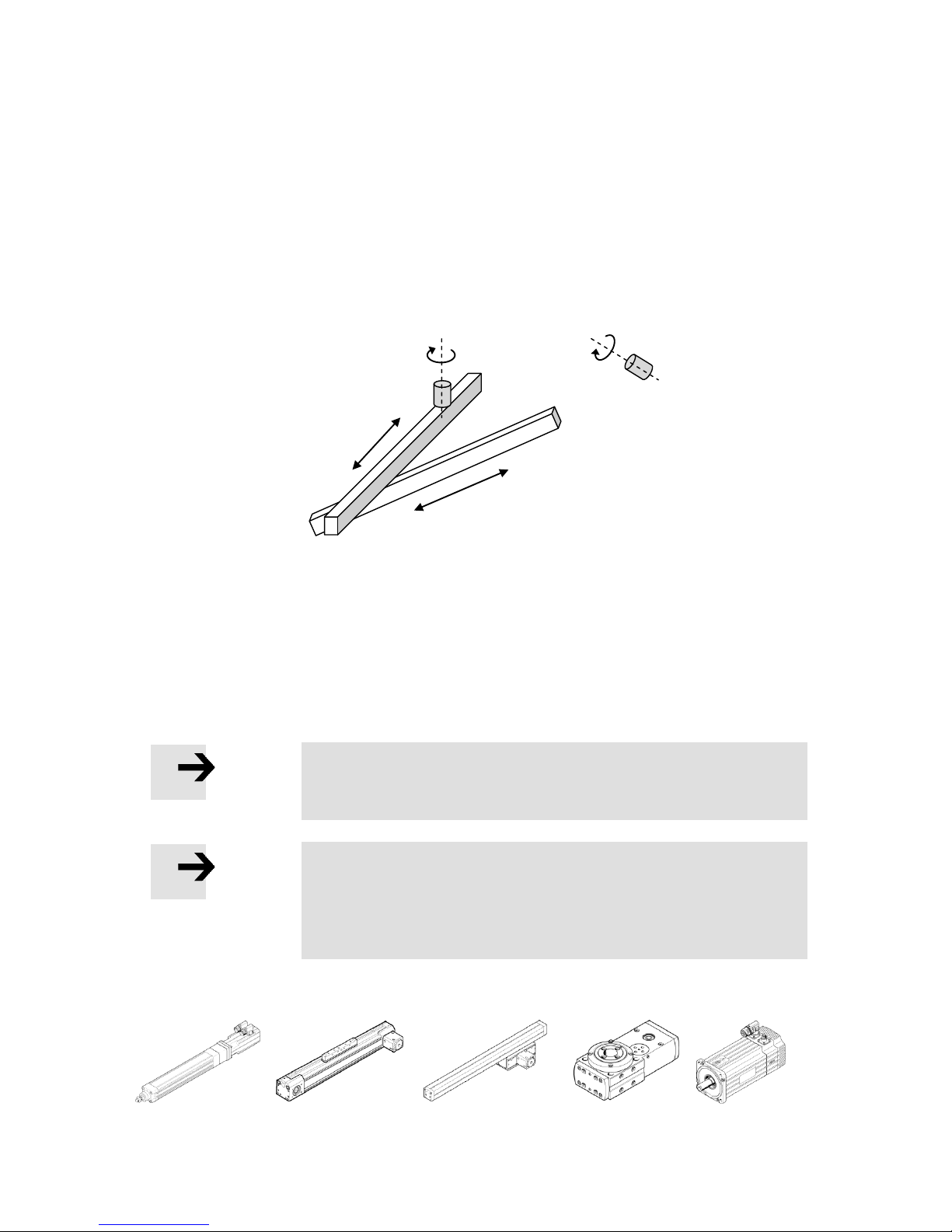
11. Supported kinematic systems
80 Festo GDCP-CMXR-C2-SY-EN 1205b
11.2 Axis interpolation
Kinematics systems for which no internal kinematics model exist can be controlled using
pure axis interpolation. This means that all movements can only be carried out as a pointto-point movement (PtP). Cartesian paths such as linear and circular interpolation are not
possible. Furthermore, there are no manual and auxiliary axes as well as no definable tools
(TCP).
The graphic shows an example of a free kinematics system with two linear axes and two
rotating axes. For this kinematics system, there is no internal model, since the arrangement of the axes is free and thus the axis sequence is undefined. For this reason, there are
no world and tool coordinate systems, but just a axis coordinate system.
The sequence of the possible linear and rotating axes is random and is determined by
configuration in the Festo Configuration Tool (FCT).
Note
The zero point of the axis coordinate system is defined by the zero
point of all axes.
Note
With a free kinematics system/axis interpolation, the mechanical
configuration of the axes is unknown. The movements can only be
carried out in a point-to-point interpolation (PtP). All functions that
operate in the Cartesian way are not allowed and lead to an error.
The illustration below shows examples of Festo linear and rotating axes:
Examples of linear axes
Examples of rotating axes
Axis 2
+
Axis 3
Axis 1
+ - -
+ + Axis 4
Page 81
11. Supported kinematic systems
Festo GDCP-CMXR-C2-SY-EN 1205b 81
11.3 Overview of all supported kinematics systems
The table below shows an overview of all kinematics models supported by CMXR-C1.
Kinematic name
Number of
basic axes
Number of
wrist axes
Auxiliary axes
Cartesian linear gantry
2
Max. 1
Max. 3
Cartesian planar surface
gantry
2
Max. 1
Max. 3
Cartesian three-dimensional
gantry
3
Max. 1
Max. 3
Tripod
3
Max. 1
Max. 3
T-gantry
2
Max. 1
Max. 3
H-gantry
2 or 3
Max. 1
Max. 3
Free kinematics
6
None
None
Table 11.7 Overview of supported kinematics
The required kinematics model is selected during configuration via the Festo Configuration
Tool (FCT).
Note
The wrist axes in the table are electric axes that interpolate with the
kinematics. Pneumatic rotary and semi-rotary drives cannot be
used here. These have to be integrated separately via the definition
of tool data.
Note
The maximum number of axes = Basic axes + wrist axes + auxiliary
axes = 6.
Page 82

11. Supported kinematic systems
82 Festo GDCP-CMXR-C2-SY-EN 1205b
A. INDEX
3
3-D gantry ........................................... 72
A
Administrator ...................................... 34
Application directory ........................... 18
Automatic mode .................................. 41
Auxiliary axes ...................................... 66
Axis coordinate system ........................ 52
Axis interpolation ................................ 81
B
Basic axes ........................................... 60
Bridge connector ................................. 30
C
CDSA ................................................... 27
Central module .................................... 14
D
Data memory ....................................... 16
Directory structure ............................... 17
E
Emergency off ...................................... 42
F
File system .......................................... 17
Front panel plug .................................. 22
H
Handheld terminal ............................... 27
H-gantry .............................................. 79
Higher-order control ............................ 48
I
Interface unit ...................................... 29
L
Linear gantry ....................................... 68
M
Manual override .................................. 41
Memory card ....................................... 16
Multi-axis control system CMXR-C2 ....... 8
O
Operating modes ................................ 41
P
Password ............................................ 33
Planar surface gantry .......................... 70
Plugs ................................................... 23
R
Reduced speed ................................... 41
Repositioning ...................................... 44
Right to write ...................................... 48
T
T-gantry .............................................. 77
Tool coordinate system ....................... 75
Tripod kinematics ............................... 74
U
User level ............................................ 50
User name........................................... 33
User rights .......................................... 33
W
Wrist axes ........................................... 61
 Loading...