

Festo CMMS-AS Series, CMMS-ST-C8-7-G2, CMMD-AS Series, CMMS-ST Series, s CMMD-AS-C8-3A Description
...Page 1
Motor controller
CMMS-AS/CMMS-ST/CMMD-AS
Description
Fuctions and
commissioning
Firmware-Version
from 1.4.0.x.6
8040107
1404NH
[8034520]
Page 2
CMMS-AS/CMMS-ST/CMMD -AS
Translation of the original instructions
GDCP-CMMS/D-FW-EN
®
CAN
,CANopen®,CiA®,CODESYS®, DeviceNet®,EnDat®,PROFIBUS®,Windows®are registered
trademarks of the respective trademark owners in certain countries.
Identification of hazards and instructions on how to prevent them:
Warning
Hazards that c an cause death or serious injuries.
Caution
Hazards that can cause minor injuries or serious material damage.
Other symbols:
Note
Material damage or loss of function.
Recommendations, tips, references to other documentation.
Essential or useful accessories.
Information on environmentally sound usage.
Text designations:
• Activities that may be carried out in any order.
1. Activities that should be carried out in the order stated.
– General lists.
2 Festo – GDCP-CMMS/D-FW-EN – 1404NH –
Page 3

CMMS-AS/CMMS-ST/CMMD -AS
Table of contents – CMMS-AS/CMMS-ST/CMMD-AS
1 Safety and requirements for product use 13......................................
1.1 Safety 13..................................................................
1.1.1 Safety instructions 13................................................
1.1.2 Intended use 14.....................................................
1.2 Requirements for product use 15...............................................
1.2.1 Transport and storage conditions 15....................................
1.2.2 Technical requirements 15............................................
1.2.3 Qualification of trained personnel 15....................................
1.2.4 Range of application and certifications 16................................
2 Product overview 17.........................................................
2.1 Motor controller CMMS-AS-C4-3A-G2 17.........................................
2.1.1 Control, sensor and safety function interfaces 17..........................
2.1.2 Power supply, motor and motor encoder interfaces 19......................
2.1.3 Parameter/firmware interfaces 21......................................
2.1.4 LED indicators, seven-segment displays and DI L switches 23.................
2.2 Motor controller CMMS-ST-C8-7-G2 25...........................................
2.2.1 Control, sensor and safety function interfaces 25..........................
2.2.2 Power supply, motor and motor encoder interfaces 27......................
2.2.3 Parameter/firmware interfaces 29......................................
2.2.4 LED indicators, seven-segment displays and DI L switches 31.................
2.3 Motor controller CMMD-AS-C8-3A 33............................................
2.3.1 Control, sensor and safety function interfaces 33..........................
2.3.2 Power supply, motor and motor encoder interfaces 35......................
2.3.3 Parameter/firmware interfaces 37......................................
2.3.4 LED indicators, seven-segment displays and DI L switches 39.................
2.4 Control interfaces – operating modes – operational functions 41......................
2.4.1 Overview: Control interfaces/connections/device profiles/
operating modes/operational functions 41...............................
2.4.2 Positioning mode: Direct mode, individual record mode,
record linking mode and interpolated positioning mode 42...................
2.4.3 Positioning mode: Homing mode/jog mode/teach mode 43..................
2.4.4 Speed mode, force mode and torque mode 44............................
2.4.5 Synchronisation 45..................................................
2.4.6 Operational functions: Encoder emulation, flying measurement,
analogue monitor and endless positioning 46.............................
Festo – GDCP-CMM S/D-FW-EN – 1404NH – English 3
Page 4

CMMS-AS/CMMS-ST/CMMD -AS
3 Control interfaces 47.........................................................
3.1 Digital, analogue, synchronisation and fieldbus interfaces 47.........................
3.1.1 Motor controller CMMS-AS-C4-3A-G2 47.................................
3.1.2 Motor controller CMMS-ST-C8-7-G2 48..................................
3.1.3 Motor controller CMMD-AS-C8-3A 49....................................
3.2 Digital interfaces [X1] [X1.1/X1.2/EXT1/EXT2] 50..................................
3.2.1 Digital I/O modules (DIN…/DOUT…) 50..................................
3.2.2 Selecting the operating mode/mode via digital input signals 50...............
3.2.3 Digital input/output signals as a function of the operating mode/mode 51......
3.2.4 Digital input signals 53...............................................
3.2.5 Digital output signals 57..............................................
3.2.6 Message “Target reached” 60..........................................
3.2.7 Message “Following error” 61..........................................
3.2.8 Message “Speed reached” 62.........................................
3.2.9 Message “Remaining distance” 65......................................
3.3 Analogue interface [X1] [X1.1/X1.2] 66...........................................
3.3.1 Analogue input/output (AIN0/AMON0) 66................................
3.3.2 Analogue input signal (analogue setpoint value specification) 66..............
3.3.3 Analogue output signal (analogue monitor) 67............................
3.4 Synchronisation interfaces [X1/X10] [X1.1/X1.2/X10.1/X10.2] 68.....................
3.4.1 Encoder input for synchronisation ( slave interface) 68......................
3.4.2 Encoder output for encoder emulation (master interface) 69.................
3.4.3 Incremental signals ( A/#A/B/#B/N/#N) 70...............................
3.4.4 Pulse/direction signals (CLK/#CLK/DIR/#DIR) 71..........................
3.4.5 Forward/reverse signals (CW/#CW/CCW/#CCW) 72........................
3.5 Fieldbus interfaces [X4] [X5] [EXT/EXT1] 73.......................................
3.5.1 Suppo rted fieldbuses 73..............................................
3.5.2 Required digital inputs/outputs with a fieldbus activation 74.................
3.6 Device profiles for fieldbuses 75................................................
3.6.1 Device profile: Festo handling and positioning profile (FHPP) 75..............
3.6.2 Device profile: CANopen, CiA 402 (for electric drives) 75....................
4 Measuring system 76........................................................
4.1 Measuring system for electrical drives 76.........................................
4.1.1 Measuring system for linear drives 76...................................
4.1.2 Measuring system for rotative drives 77..................................
4.2 Calculation rules for the measuring system 78.....................................
4.3 Limit switch (hardware) and software end position 78...............................
4.3.1 Limit switch LSN/LSP (hardware) 78....................................
4.3.2 Software end position SLN/SLP 78......................................
4 Festo – GDCP-CMMS/D-FW-EN – 1404NH – English
Page 5

CMMS-AS/CMMS-ST/CMMD -AS
5 Commissioning 79...........................................................
5.1 Configuration/parameterisation of the drive system and motor controller 79.............
5.1.1 Festo Configuration Tool (FCT) 79.......................................
5.1.2 Installing the FCT framework/plug-in 80..................................
5.1.3 Configuring/parameterising the Festo Configuration Tool (FCT) 80.............
5.1.4 FCT Help 81........................................................
5.1.5 Configuring fieldbus/firmware functions via DIL switch 82...................
5.1.6 Fieldbus address/MAC-ID configuration 83...............................
5.1.7 Firmware download activation from the memory c ard 84....................
5.1.8 Data rate configuration (CAN bus/DeviceNet) 84..........................
5.1.9 CAN bus activation 84................................................
5.1.10 Terminating resistor activation (CAN bus) 85..............................
5.2 Data interfaces (parameter/firmware) 86.........................................
5.2.1 Firmware file 87.....................................................
5.2.2 Downloading the firmware file ( FCT >> motor controller) 87...................
5.2.3 Downloading the firmware file ( .S) (memory card >> motor controller) 88........
5.2.4 Device data ( FCT) 90.................................................
5.2.5 Downloading/synchronising/uploading/saving device data
(FCT <</<=>/>> motor controller) 90......................................
5.2.6 Archiving/extracting device data (FCT >>/<< PC) 92..........................
5.2.7 Parameter file (.DCO) 93..............................................
5.2.8 Reading/writing/saving the parameter file ( .DCO)
(memory card >>/<< motor c ontroller) 94..................................
5.3 Commissioning the motor controller 95..........................................
5.3.1 Preparing for initial start -up 95.........................................
5.3.2 Required digital inputs/outputs for operation 96..........................
5.3.3 Status diagram of the motor controller 97................................
5.3.4 Switching on the power supply (Power ON) 98............................
5.3.5 Downloading device data (FCT) to the motor controller 100...................
5.3.6 Enabling the motor c ontroller via digital inputs 101..........................
5.3.7 Commutation finding by motor controller CMMS-ST-C8-7-G2 103...............
5.3.8 Checking motor and limit switch functionality 104...........................
5.3.9 Carrying out homing 105...............................................
5.4 Behaviour of the motor controller in the event of an interruption or disconnection 106......
5.4.1 Holding brake 106....................................................
5.4.2 Interruption of the mains supply 107.....................................
5.4.3 Switching off the motor controller via output stage enable (DIN4) 108..........
5.4.4 Switching off the motor controller via controller enable (DIN5) 109.............
5.5 Master control 110............................................................
5.5.1 Master control over the motor controller 110...............................
5.5.2 FCT master control over the motor controller 112...........................
Festo – GDCP-CMM S/D-FW-EN – 1404NH – English 5
Page 6

CMMS-AS/CMMS-ST/CMMD -AS
6 Positioning mode 113.........................................................
6.1 Function: Position c ontrol 113...................................................
6.2 Record selection and positioning records 114......................................
6.2.1 Function: Record selection and positioning records 114......................
6.2.2 Record selection (positioning record) – control interface – operating mode 115...
6.3 Relative positioning 115.......................................................
6.4 Direct mode 116..............................................................
6.4.1 Function: Direct mode 116.............................................
6.4.2 Connection: Digital inputs/outputs 117...................................
6.4.3 Parameterising the direct mode 118......................................
6.5 Individual record mode 120.....................................................
6.5.1 Function: Individual record mode 120....................................
6.5.2 Connection: Digital inputs/outputs 121...................................
6.5.3 Timing diagram: Start/cancel individual record 123.........................
6.5.4 Parameterising the individual record mode 125.............................
6.6 Record linking mode 137.......................................................
6.6.1 Function: Record linking mode 137.......................................
6.6.2 Connection: Digital inputs/outputs 138...................................
6.6.3 Timing diagram: Start/interrupt/cancel record sequence 140.................
6.6.4 Parameterising the record linking mode 144...............................
6.7 Interpolated positioning mode 153...............................................
6.7.1 Function: Interpolated positioning mode 153..............................
6.7.2 Connection: Digital inputs/outputs 154...................................
6.8 Homing mode/homing 155.....................................................
6.8.1 Function: Homing mode 155............................................
6.8.2 Connection: Digital inputs/outputs 156...................................
6.8.3 Timing diagram: Cancelling homing to limit switch/stop 158..................
6.8.4 Configuring and parameterising the homing mode/homing 162................
6.9 Jog mode 172................................................................
6.9.1 Function: Jog mode 172................................................
6.9.2 Jog mode via Festo Configuration Tool (FCT) 173............................
6.9.3 Connection: Digital inputs/outputs 174...................................
6.9.4 Timing diagram: Jog travel via jog+/jog– 175...............................
6.9.5 Parameterise jog mode 177............................................
6.10 Teach mode 178..............................................................
6.10.1 Function: Teach mode 178.............................................
6.10.2 Connection: Digital inputs/outputs 179...................................
6.10.3 Timing diagram: Teaching the current actual position of the drive 181...........
6.10.4 Parameterising the teach mode 182......................................
6 Festo – GDCP-CMMS/D-FW-EN – 1404NH – English
Page 7

CMMS-AS/CMMS-ST/CMMD -AS
7 Speed mode and force/torque mode 183..........................................
7.1 Speed mode 183.............................................................
7.1.1 Function: Speed adjustment 183........................................
7.1.2 Function: Speed mode 184.............................................
7.1.3 Connection: Analogue and digital inputs/outputs 185.......................
7.1.4 Parameterise speed mode 186..........................................
7.2 Force/torque mode 188........................................................
7.2.1 Function: Current regulation 188........................................
7.2.2 Function: Force/torque mode 189.......................................
7.2.3 Connection: Analogue and digital I/O modules 190..........................
7.2.4 Parameterise force/torque mode 191....................................
8 Synchronisation 193..........................................................
8.1 Synchronisation (slave mode) 193...............................................
8.1.1 Function: Synchronisation 193..........................................
8.1.2 Connection: Digital inputs/outputs (24 V) and encoder input (5 V) 195..........
8.1.3 Connection: Digital inputs/outputs (24 V) 196..............................
8.1.4 Timing diagram: Starting synchronisation via Start Sync signal 197.............
8.1.5 Configure/parameterise synchronisation 198..............................
9 Operational functions 199.....................................................
9.1 Encoder emulation (master operation) 199........................................
9.1.1 Function: Encoder emulation 199........................................
9.1.2 Connection: Encoder output (5 V) 200....................................
9.1.3 Configure/parameterise encoder emulation 200............................
9.2 Flying measurement (sampling) 201..............................................
9.2.1 Function: Flying measurement 201.......................................
9.2.2 Connection: Digital input 202...........................................
9.3 Analogue monitor 203.........................................................
9.3.1 Function: Analogue monitor 203.........................................
9.3.2 Connection: Analogue output 203.......................................
9.3.3 Configure/parameterise analogue monitor 204.............................
9.4 Endless positioning 206........................................................
9.4.1 Function: Endless positioning 206.......................................
9.5 Resonance filter (motor controller CMMS-ST-C8-7-G2) 208............................
9.5.1 Function: Resonance filter 208..........................................
Festo – GDCP-CMM S/D-FW-EN – 1404NH – English 7
Page 8

CMMS-AS/CMMS-ST/CMMD -AS
10 Service 209.................................................................
10.1 Protective and service functions 209..............................................
10.1.1 Overload current and short-circuit monitoring of the motor output 210..........
10.1.2 Monitoring of interruption and failure of the mains supply 210.................
10.1.3 Overvoltage and undervoltage monitoring for the intermediate c ircuit 210.......
10.1.4 Output stage temperature monitoring 210.................................
10.1.5 Monitoring the motor and motor encoder 210..............................
10.1.6 I2t monitoring 211....................................................
10.2 Operating mode and error messages 213..........................................
10.2.1 LED indicators (Ready/CA N/Bus) 213....................................
10.2.2 Seven-segments display 213...........................................
10.3 Acknowledgement of error messages 215.........................................
10.3.1 Diagnostic messages 215..............................................
10.4 Dismantling and repairs 216....................................................
10.4.1 Saving the parameter set for the motor controller 216.......................
A Diagnostic messages 217......................................................
A.1 Explanations on the diagnostic messages 217......................................
A.2 Diagnostic messages with instructions for fault clearance 218.........................
A.3 Error codes via CiA 301/402 231.................................................
A.4 Profibus diagnostics 233.......................................................
B Serial interface RS232 (diagnostics/parameterisation interface) 236..................
B.1 Activating the motor controller via the interface RS232 236...........................
B.1.1 Master data of the interface RS 232 236...................................
B.1.2 Connect RS232 interface with a program 236..............................
B.1.3 Connection [X5]: Pin allocation of the RS232 interface 237...................
B.2 Commands/syntax of the RS232 interface 238......................................
B.2.1 General c ommands 238...............................................
B.2.2 Control motor controller via CAN-Interpreter (CI) 238........................
C Serial interface RS485 (control interface) 241.....................................
C.1 Activating the motor controller via the interface RS485 241...........................
C.1.1 Master data of the interface RS485 241...................................
C.1.2 Connection [X5]: Pin allocation of the RS 485 interface 241...................
C.2 Configure RS485 interface in the Festo Configuration Tool (FCT) 242....................
C.3 Commands/syntax o f the RS48 5 interface 243......................................
8 Festo – GDCP-CMMS/D-FW-EN – 1404NH – English
Page 9
CMMS-AS/CMMS-ST/CMMD -AS
Instructions on this description
This documentation is intended to help you work safely with the motor controller CMMS-AS/CMMS-ST/
CMMD-AS and describes the functions, commissioning procedure and error messages.
Tar g et grou p
This documentation is intended exclusively for technicians trained in control and automation techno-
logy, who have experience in installation, commissioning, programming and diagnostics of positioning
systems.
Vers i ons
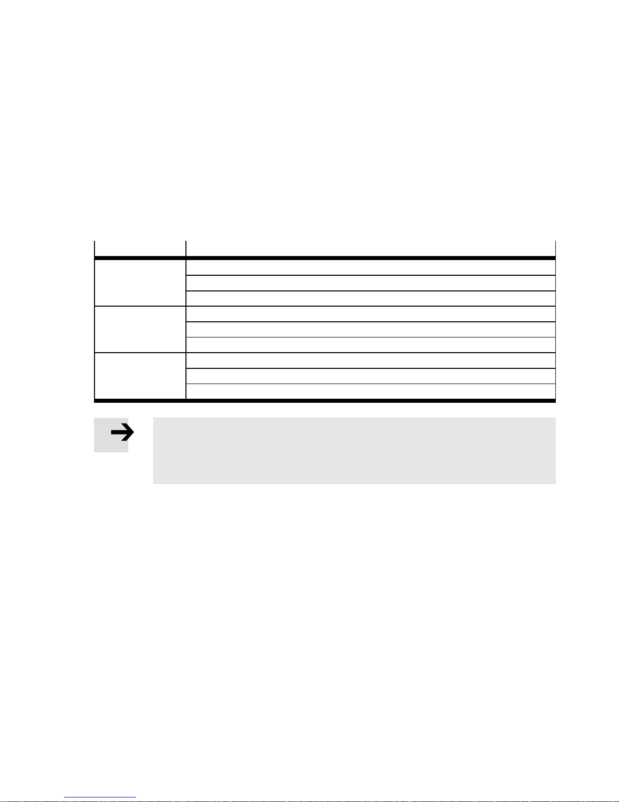
This documentation refers to the following versions:
Motor controller
Vers i on
CMMS-AS-... Motor controller CMMS-AS-C4-3A-G2: From Rev 03
Firmware: From version 1.4.0.2.6
FCT plug-in CMMS-AS: From version 2.0.0.x
CMMS-ST-... Motor controller CMMS-ST-C8-7-G2: From Rev 05
Firmware: From version 1.4.0.1.6
FCT plug-in CMMS-ST: From version 2.0.0.x
CMMD-AS-... Motor controller CMMD-AS-C8-3A: From Rev 03
Firmware: From version 1.4.0.3.6
FCT plug-in CMMD-AS: From version 2.0.0.x
Note
Before using a newer firmware version, check whether a newer version of the FCT plugin or documentation is available
Support portal: http:// www.festo.com/sp.
Service
Please consult your regional Festo contact if you have any technical problems.
Product identification
For additional information about the rating plate and manufacturing date “Mounting and installa-
tion” description, GDCP-CMMS-AS-G2-HW-…/GDCP-CMMD-AS-HW-…/GDCP-CMMS-ST-G2-HW-…
Festo – GDCP-CMM S/D-FW-EN – 1404NH – English 9
Page 10
CMMS-AS/CMMS-ST/CMMD -AS
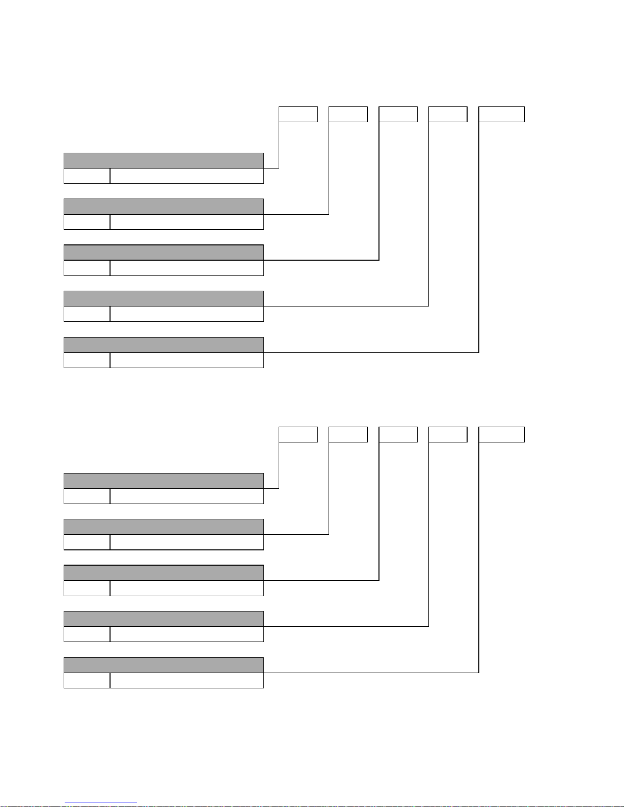
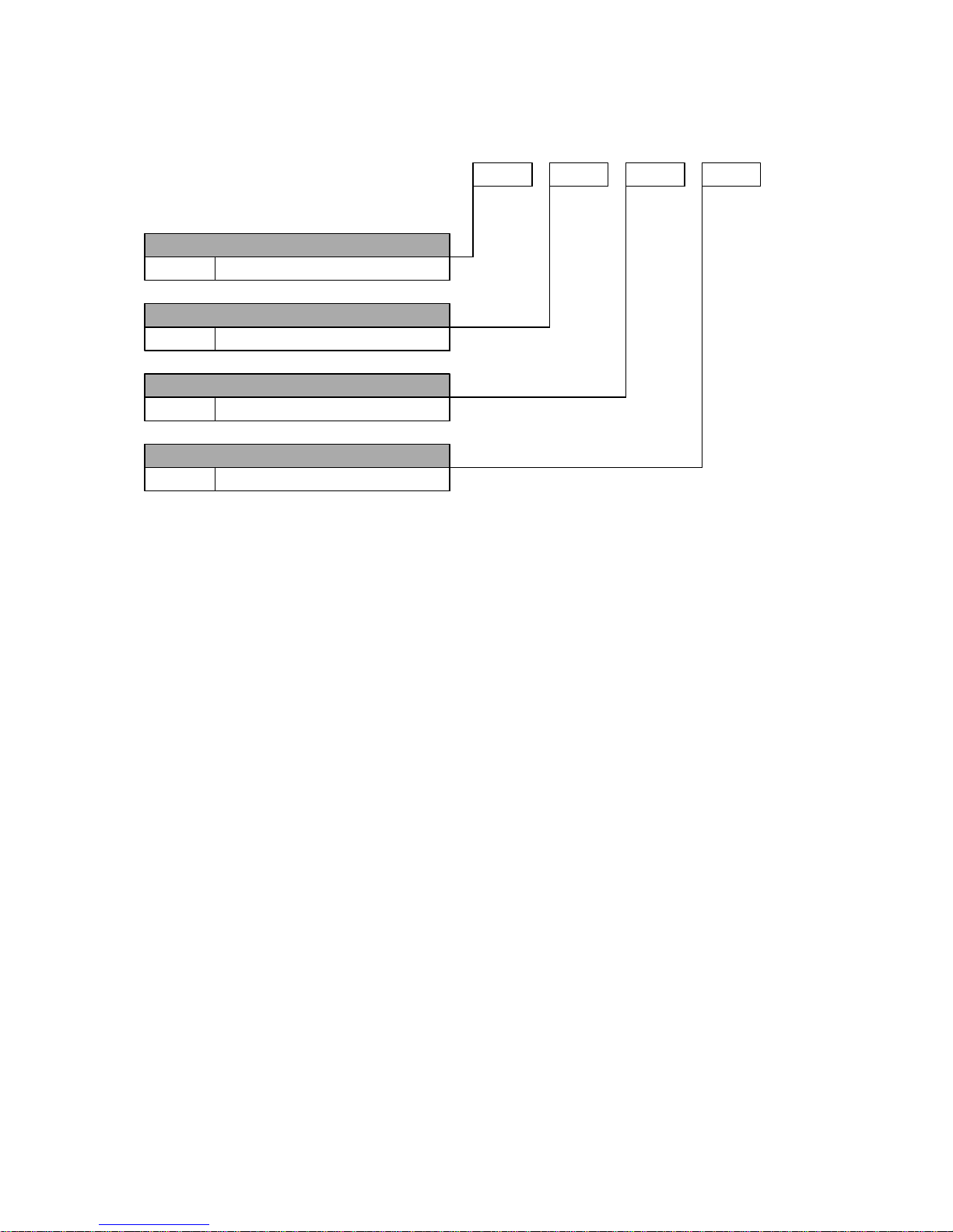
Type codes CMMS-AS-C4-3A-G2
Interfaces
CMMS Motor controller, standard
Motor technology
AS AC synchronous
Nominal current
C4 4 A
Input voltage
3 A 230 V AC
Generation
G2 2nd generation
Fig. 1 Type codes CMMS-AS-C4-3A-G2
CMMS
AS C4 3 A G2
–
–––
Type codes CMMS-ST-C8-7-G2
Interfaces
CMMS Motor controller, standard
Motor technology
ST Stepper motor
Nominal current
C8 8 A
Input voltage
748VDC
Generation
G2 2nd generation
Fig. 2 Type codes CMMS-ST-C8-7-G2
CMMS
ST C8 7 G2
–
–––
10 Festo – GDCP-CMMS/D-FW-EN – 1404NH – English
Page 11
CMMS-AS/CMMS-ST/CMMD -AS
Type codes CMMD-AS-C8-3A
Interfaces
CMMD Motor controller, double
Motor technology
AS AC synchronous
Nominal current
C8 8 A
Input voltage
3 A 230 V AC
Fig. 3 Type codes CMMD-A S -C8-3A
CMMD
AS C8 3 A
–
––
Festo – GDCP-CMM S/D-FW-EN – 1404NH – English 11
Page 12
CMMS-AS/CMMS-ST/CMMD -AS
–
y
gg
Documentation
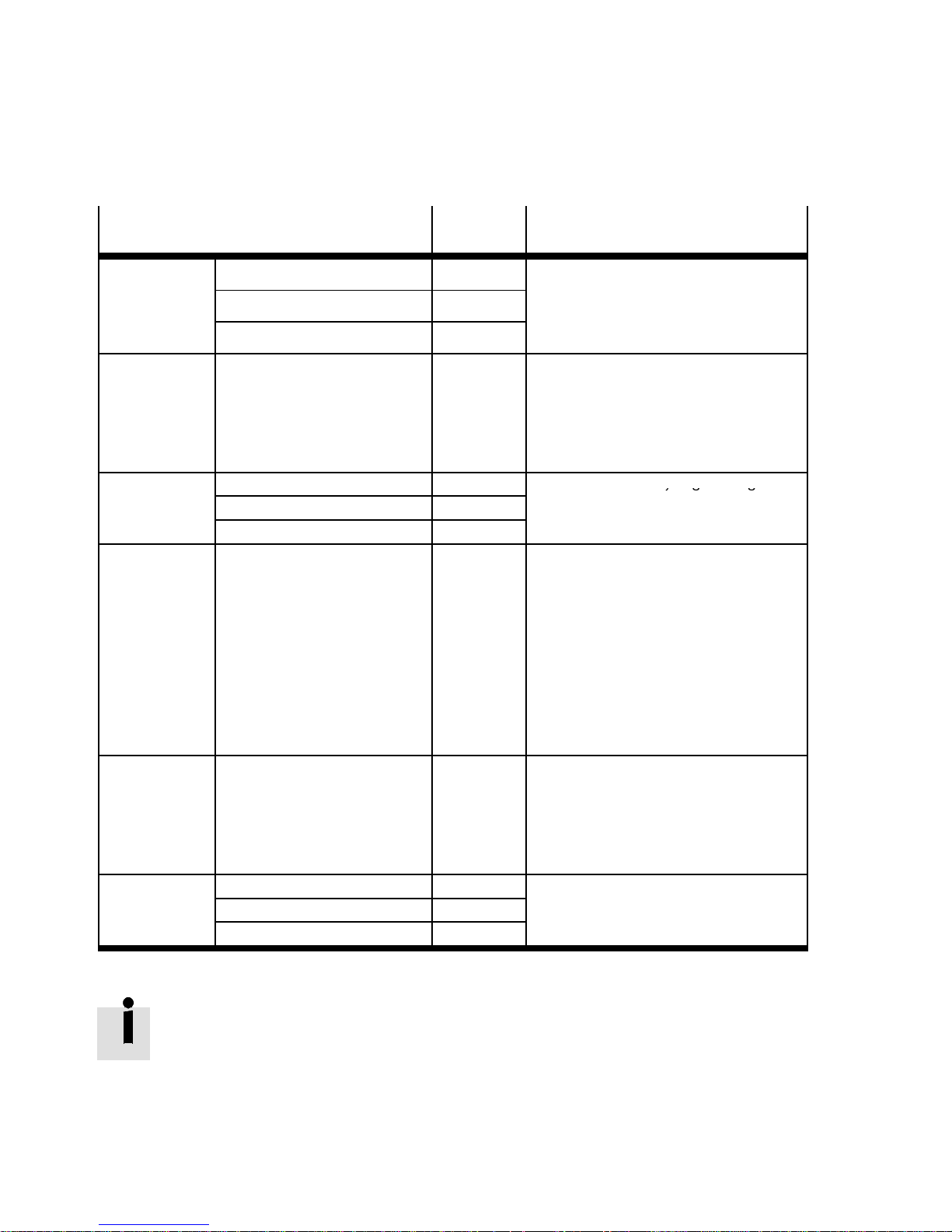
Additional information on the motor controllers CMMS-AS/CMMS-ST/CMMD-AS can be found in the
following documentation:
Documentation
Device
Contents
type
Assembly and
installation
GDCP-CMMS-AS-G2-HW-... CMMS-AS –Mounting
GDCP-CMMD-AS-HW-... CMMD-AS
Installation (pin allocations)
– Error messages
Functions and
commissioning
GDCP-CMMS-ST-G2-HW-... CMMS-ST
GDCP-CMMS/D-FW-... CMMS-AS
CMMD-AS
CMMS-ST
– Technical data
– Control interfaces
– Operating modes/operational
functions
– Commissioning with FCT
– Error messages
STO safety
function
Device
profile FHPP
GDCP-CMMS-AS-G2-S1-... CMMS-AS – Functional safety engineering with
GDCP-CMMD-AS-S1-... CMMD-AS
GDCP-CMMS-ST-G2-S1-... CMMS-ST
GDCP-CMMS/D-C-HP-... CMMS-AS
CMMD-AS
CMMS-ST
the STO safety function (Safe
Torque Off )
– Description of the interfaces:
– CAN bus (CANopen)
–InterfaceCAMC-PB(PROFIBUS)
– Interface CAMC-DN (DeviceNet)
– Control and parameterisation via
the device profile FHPP (Festo
Handling and Positioning Profile)
with PROFIBUS, DeviceNet or
CANopen.
Device profile
CiA 402
GDCP-CMMS/D-C-CO-... CMMS-AS
CMMD-AS
CMMS-ST
– Description of the interface:
– CAN bus (CANopen, DriveBus)
– Control and parameterisation via
the device profile CiA 402 (DS
402).
Software Help Help for the CMMS-AS plug-in CMMS-AS – User interface and functions in the
Help for the CMMD-AS plug-in CMMD-AS
Help for the CMMS-ST plug-in CMMS-ST
Festo Configuration Tool for the
plug-in
Tab. 1 Documentation on the motor c ontrollers
The documentation is available on the following media:
– CD-ROM (scope of delivery)
– Support Portal: www.festo.com/sp
12 Festo – GDCP-CMMS/D-FW-EN – 1404NH – English
Page 13
1 Safety and requirements for product use
1 Safety and requirements f or product use
1.1 Safety
1.1.1 Safety instructions
Warning
Danger of electric shock
Touching live parts c auses severe injuries and can lead to death:
– when the module or c over plate is not mounted on the c ard slots [EXT]
(CMMS)/[EXT1/EXT2] (CMMD)
– when cables are not mounted to the plugs [X6] (CMMS)/[X6.1/X6.2] (CMMD) and
[X9]
– when connecting cables are disconnected when powered.
The product must be installed in a control cabinet and may only be used if all safeguarding has been initiated.
Before touching live par ts during maintenance, repair and cleaning work and when there
have been long service interruptions:
1. Switch off power to the electrical equipment via the mains switch and secure it
against being switched on again.
2. After switch-off, wait at least 5 minutes discharge time and check that power is
turned off before accessing the controller.
Caution
Danger of burns from hot surfaces
Dependent on the load of the motor controller, housing temperatures > 80 °C are possible in operation.
• Protect hot surfaces from contact in operation.
• Touch them only in a switched-off, cooled-off status.
Note
Danger from unexpected movement of the motor or axis
• Make sure that the movement does not endanger anyone.
• Perform a risk assessment in accordance with the EC machinery directive.
• Based on this risk assessment, design the safety system for the entire machine,
taking into account all integrated components. This also includes the electric drives.
Bypassing of safety equipment is impermissible.
Festo – GDCP-CMM S/D-FW-EN – 1404NH – English 13
Page 14

1 Safety and requirements for product use
1.1.2 Intended use
Motor controller CMMS-AS:
The motor controller is intended for use as a controller for a 3-phase servo motor of the EMMS-AS
series in a closed loop ( with motor encoder/closed loop).
Motor controller CMMS-ST:
The motor controller CMMS-ST is intended for use as a controller for a 2-phase stepper motor of the
EMMS-ST/MTR-ST series in a c losed loop (with motor encoder/closed loop) or in an open loop (without
motor encoder/open loop).
Motor controller CMMD-AS:
The motor controller is intended for use as a controller for two 3-phase servo motors of the E MMS-AS
series in a closed loop ( with motor encoder/closed loop).
Motor controller CMMS-AS/CMMS-ST/CMMD-AS:
All motor controllers enable the regulation of current, speed and position, and they contain a positioning controller with stored positioning records. The motor controller is designed for installation in a control cabinet.
The product is intended for use in industrial environments. Outside of industrial environments, e.g. in
commercial and mixed-residential areas, actions to suppress interference may have to be taken.
Use exclusively:
– In faultless technical condition
– In original status without unauthorised modifications; only the expansions described in the docu-
mentation supplied with the product are permitted.
– Within the limits of the product defined through the technical data
“Mounting and installation” description,
GDCP-CMMS-AS-G2-HW-…/GDCP-CMMD-AS-HW-…/GDCP-CMMS-ST-G2-HW-…
– In an industrial environment
– In a control cabinet.
In the event of damage caused by unauthorised manipulation or other than intended use, the guarantee is invalidated and the manufacturer is not liable for damages.
The motor controller supports the following safety function:
– “Safe torque off ” (STO)
Additional information “STO safety function” description,
GDCP-CMMS-AS -G2-S1-.../GDCP-CMMS-ST-G2-S1-.../GDCP-CMMD-AS-S1-....
14 Festo – GDCP-CMMS/D-FW-EN – 1404NH – English
Page 15

1 Safety and requirements for product use
1.2 Requirements for product use
• Make this documentation available to the design engineer, installer and personnel responsible for
commissioning the machine or system in which this product is used.
• Make sure that the specifications of the documentation are always complied with. Also consider the
documentation for the other components and modules.
• Take into consideration the legal regulations applicable for the destination as well as:
– Regulations and standards,
– Regulations of the testing organisations and insurers,
– National specifications.
1.2.1 Transport and storage conditions
• Protect the product during transport and storage from impermissible burdens, such as:
– Mechanical loads
– Impermissible temperatures
– Moisture
– Aggressive atmosphere
• Store and transport the product in its original packaging. The original packaging of fers sufficient
protection from typical stresses.
1.2.2 Technical requirements
For correct and safe use of the product:
• Comply with the connection and ambient conditions of the product specified in the technical data
“Mounting and installation” description, GDCP-CMMS-AS-G2-HW-…/GDCP-CMMD-AS-HW-…/
GDCP-CMMS-ST-G2-HW-…, Appendix A.1, and of all connected components. Compliance with the
limit values and load limits permits operation of the product in compliance with the relevant safety
regulations.
• Observe the instructions and warnings in this documentation.
1.2.3 Qualification of trained personnel
The product may only be placed in operation by a qualified electrotechnician who is familiar with:
– Installation and operation of electrical control systems,
– The applicable regulations for operating safety-engineered systems,
– The applicable regulations for accident protection and operational reliability, and
– The documentation for the product.
1.2.4 Range of application and certifications
The motor controller with integrated STO safety function is a safety-related part of the control systems.
The motor controller carries the CE marking; for standards and test values
“Mounting and installation” description, GDCP-CMMS-AS-G2-HW-…/GDCP-CMMD-AS-HW-…/
GDCP-CMMS-ST-G2-HW-…, Appendix A.1.
The product-relevant EU directives can be found in the declaration of conformity.
Certificates and the declaration of conformity for this product www.festo.com/sp
Festo – GDCP-CMM S/D-FW-EN – 1404NH – English 15
Page 16
2Interfaces
2 Product overview
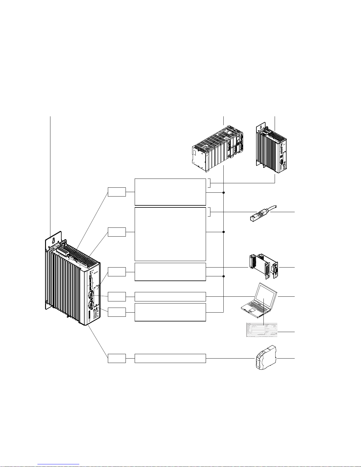
2.1 Motor controller CMMS-AS-C4-3A-G2
2.1.1 Control, sensor and safety function interfaces
1
X10
X1
EXT
A/#A/B/#B/N/#N
CLK/#CLK/DIR/#DIR
CW/#CW/CCW/#CCW
DIN0…13
DOUT0…3
AIN0/#AIN0
AMON0
CLK/#CLK/DIR/#DIR
CW/#CW/CCW/#CCW
DeviceNet
PROFIBUS DP
2
3
4
5
X5
X4
X3
Fig. 2.1 Overview: Control, sensor and safety function interfaces
16 Festo – GDCP-CMMS/D-FW-EN – 1404NH – English
RS485
CANOpen
DriveBus
STO
6
7
8
Page 17
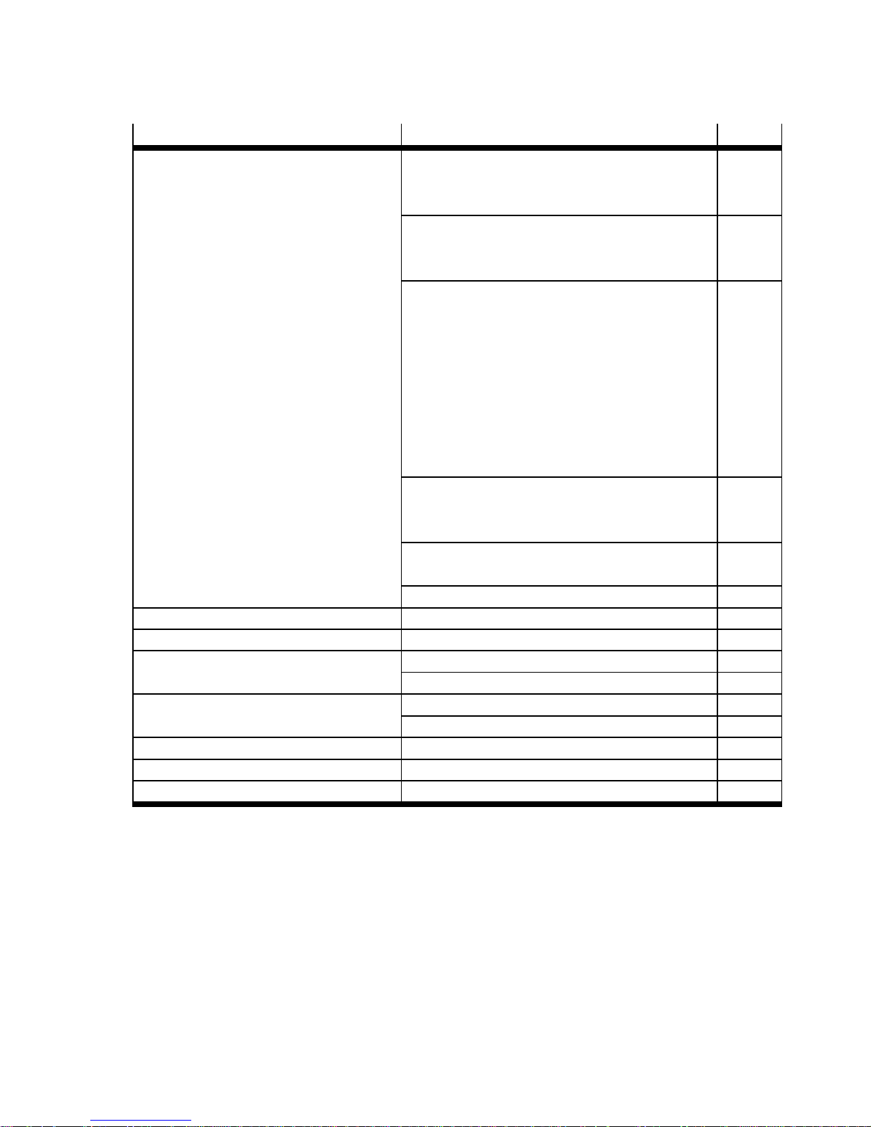
2Interfaces
Interface Function Page
1 Motor controller CMMS-AS-
C4-3A-G2
Digital interface [X1]
– Digital inputs (DIN0…13) 50
– Digital outputs (DOUT0…3) 50
Analogue interface [X1]
– Analogue inputs (AIN0/#AIN0) 65
– Analogue output (AMON0) 66
Synchronisation interfaces [X1][X10]
– Encoder inputs 67
– Encoder outputs 68
– Incremental signals
69
(A/#A/B/#B/N/#N)
– Pulse/direction signals [X10]
70
(CLK/#CLK/DIR/#DIR)
– Forward/reverse signals [X10]
71
(CW/#CW/CCW/#CCW)
CAN interface [X4]
–CANopen 72
–DriveBus 72
Slot [EXT]
– Interface module CAMC-... 5 72
RS485 interface [ X5] 240
2 Control Master device
3 Motor controller CMM... Master or slave device
4 Sensors Limit switches 77
Sequence control (N EXT1/2) 148/
5 Interface module CAMC-... DeviceNet (CAMC-DN) 72
PROFIBUS DP ( CAMC-PB) 72
6 PC Master device, RS485 interface
7 Festo Configuration Tool (FCT) Jog/individual step 172
8 Safety switching device Safety function STO (Safe Torque Off) 12
Tab. 2.1 Overview: Control, sensor and safety function interfaces
Festo – GDCP-CMM S/D-FW-EN – 1404NH – English 17
Page 18
2Interfaces
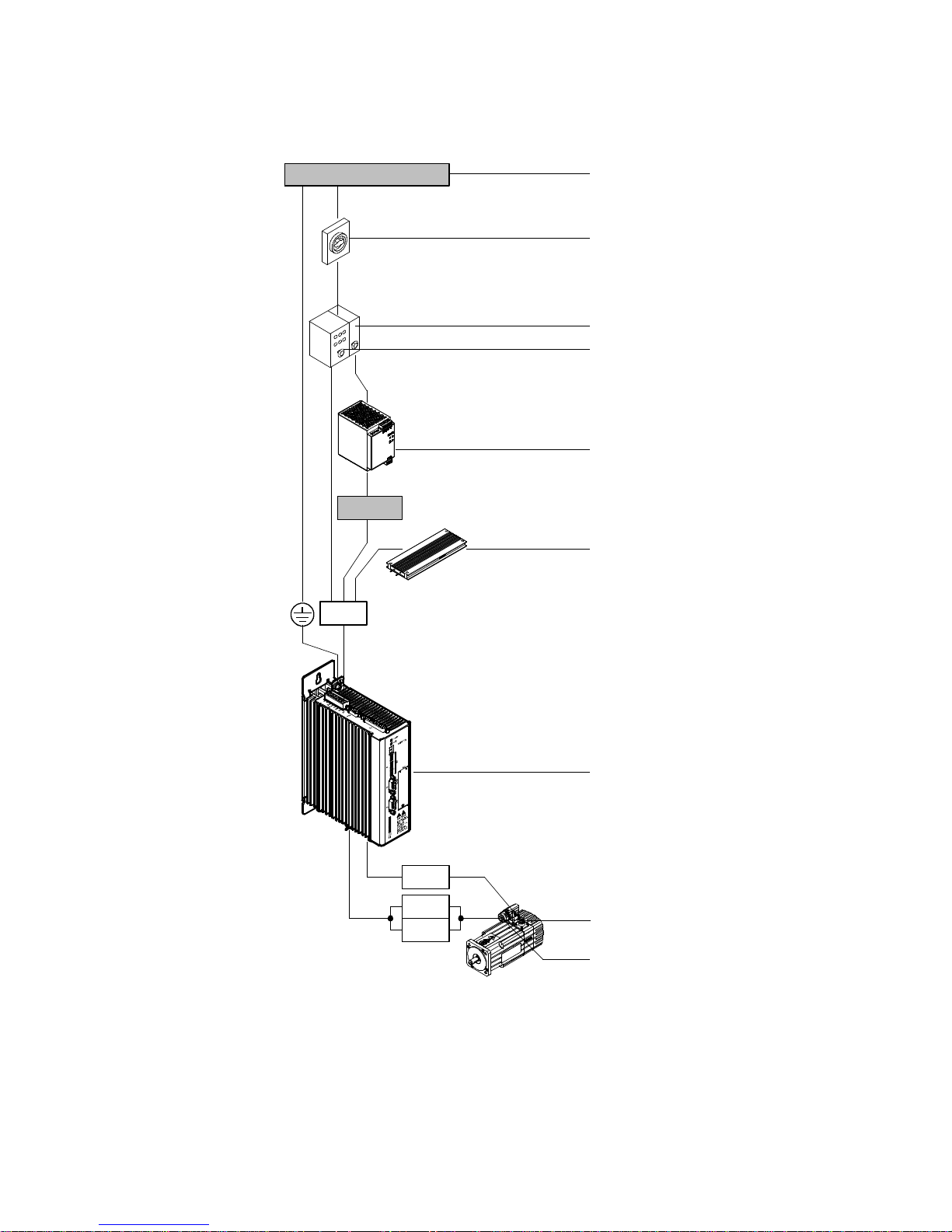
2.1.2 Power supply, motor and motor encoder interfaces
1 x 110 … 230 V AC
Power ON/OFF
24 V DC
X9
1
2
3
4
5
6
Fig. 2.2 Overview: Power supply, motor and motor encoder interfaces
18 Festo – GDCP-CMMS/D-FW-EN – 1404NH – English
X2
X6
GND
7
8
9
Page 19
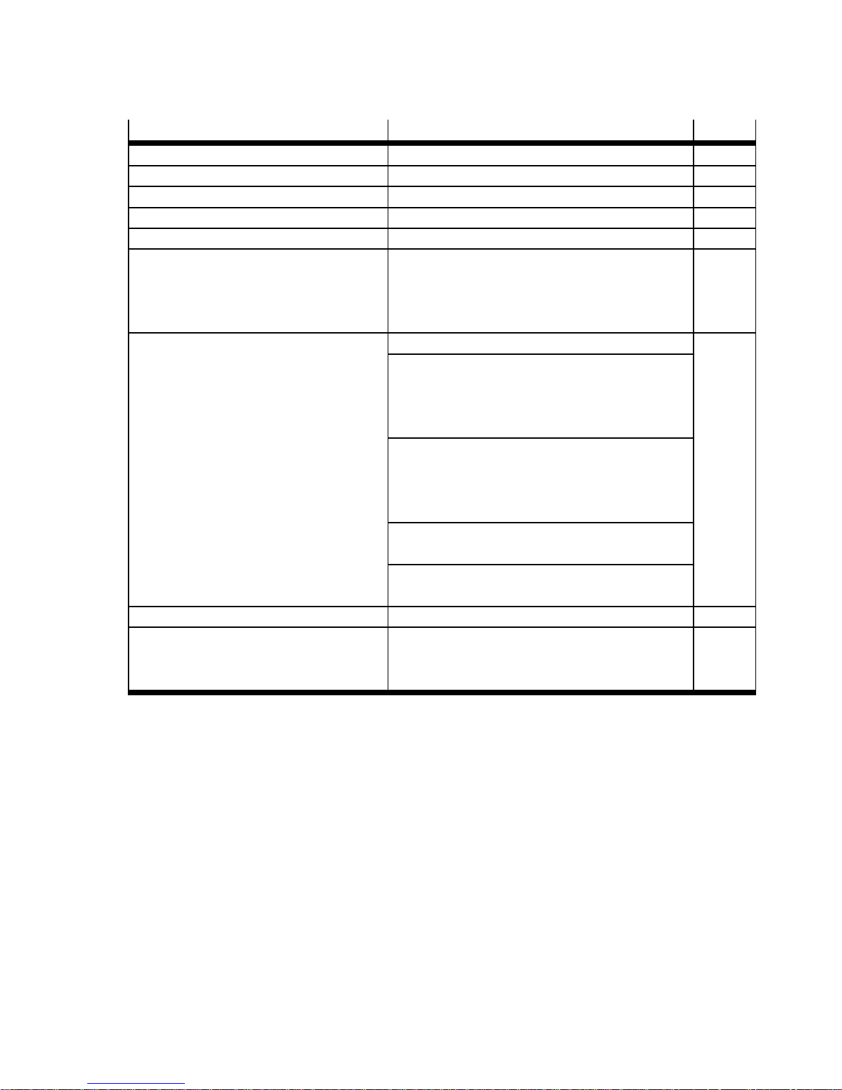
2Interfaces
Interface Function Page
1 Mains supply
2 Power switch
3 Fuse “control section” Application-dependent
4 Fuse “power section” Application-dependent
5 Power supply unit “control section” Output voltage: 24 V DC
6 External braking resistor
(optional)
–Resistance≥ 100 Ω
– Rated output ≤ 100 W
– Pulse power ≤ 1600 W
– Nominal voltage 400 V AC
7 Motor controller
CMMS-AS-C4-3A-G2
Protective earthing “ (housing) 12
Power supply [X9]
– Power section: 230 V AC (L1/N/PE)
– Control section: 24 V DC (24 V/0 V)
– External braking resistor (ZK+/BR-CH)
Motor interfaces [X6]
– Motor (U/V/W/PE)
– Holding brake (BR+/BR–)
– Motor temperature sensor (MT+/MT–)
Motor encoder [X2]
–EnDatinterface
Terminal “motor cable screening GN D”
(connected with protective earthing “)
8 Motor encoder (closed loop) EnDat interface 12
9 Servo motor EMMS-AS – Motor (U/V/W/PE)
12
– Holding brake (BR+/BR–)
– Motor temperature sensor (MT+/MT–)
Tab. 2.2 Overview: Power supply, motor and motor encoder interfaces
Festo – GDCP-CMM S/D-FW-EN – 1404NH – English 19
Page 20
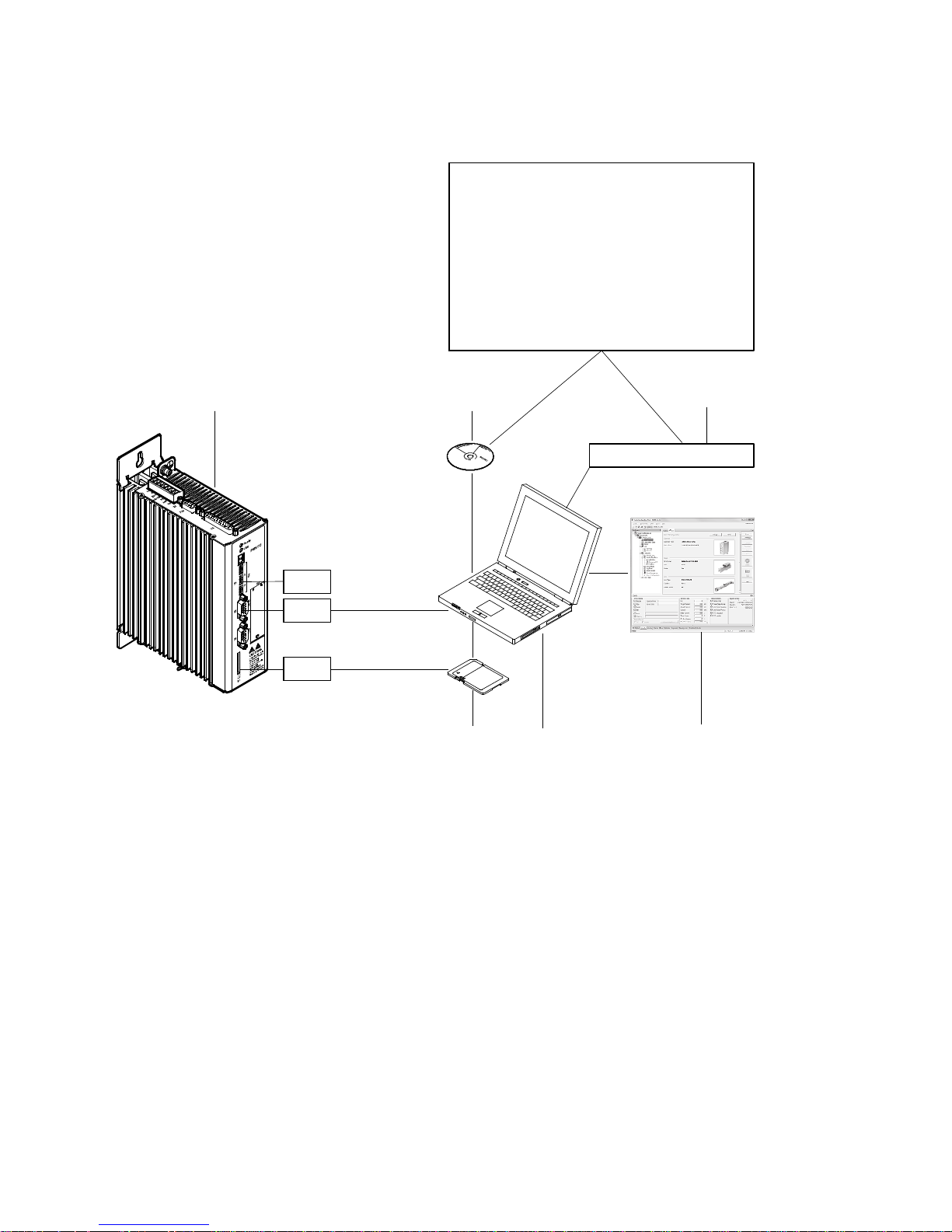
2Interfaces
2.1.3 Parameter/firmware interfaces
123
Festo Configuration Tool (FCT)
Framework/plug-in
Firmware files
Device-descriptive files
EDS/GSD
Function block files
CodeSys/Step7/RSLogix 5000
Documentation
www.festo.com/sp
S1.8
Fig. 2.3 Overview: Parameter/firmware interfaces
X5
M1
Download
Upload
Read
Write
56
4
20 Festo – GDCP-CMMS/D-FW-EN – 1404NH – English
Page 21
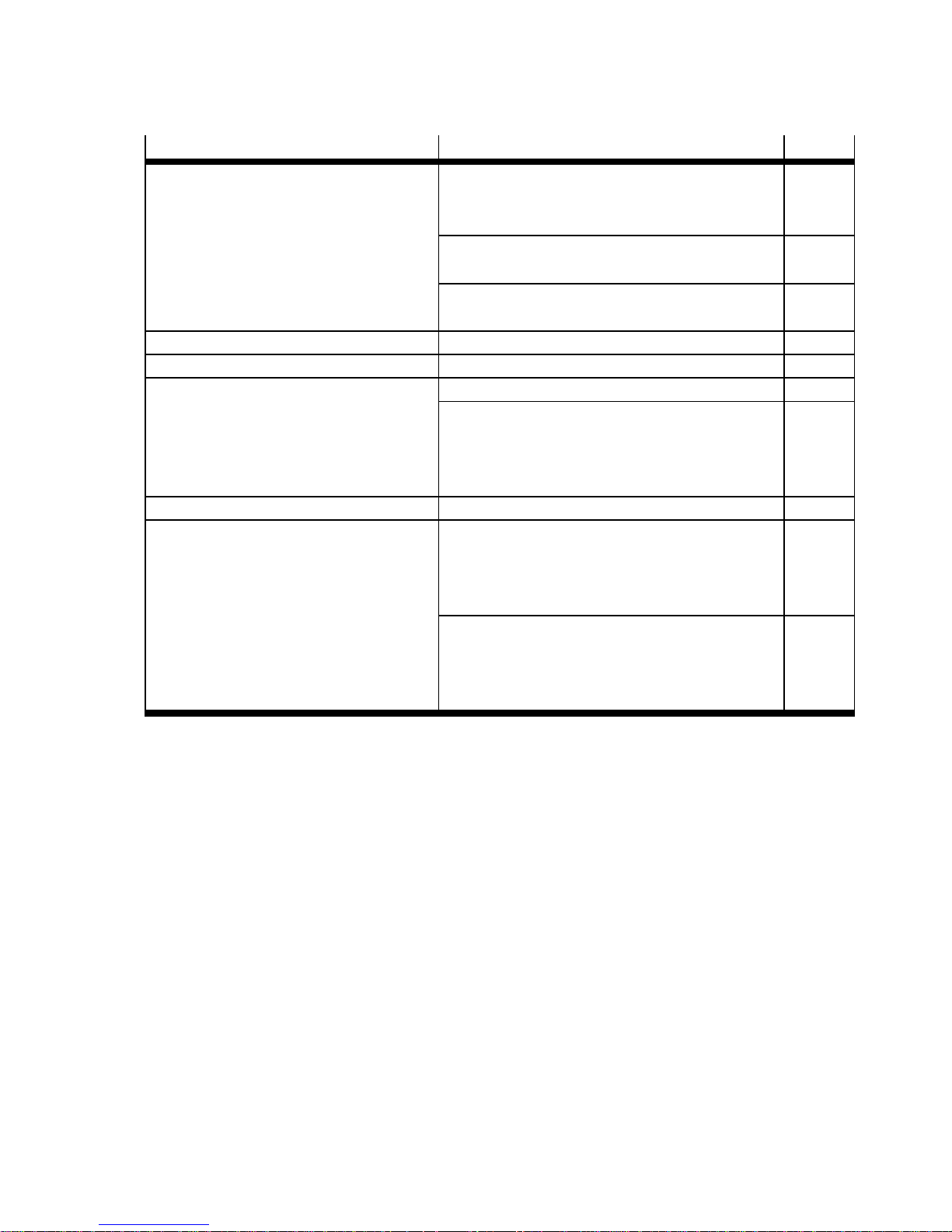
2Interfaces
Interface Function Page
1 Motor controller
CMMS-AS-C4-3A-G2
DIL switch [S1.8]
– Firmware download activation from the
83
memory card
RS232 interface [X5]
– Onlinedatainterface
235
Card slot [M1]
– Slot for memory card
2 CD-ROM Included in the scope of delivery
3 Internet Support Portal: www.festo.com/sp
4 Festo Configuration Tool (FCT) Parameterisation/configuration 79
Data transfer control
– Firmware file 86
– Device data (FCT) 89
– Parameter set data (motor controller) 92
5 PC Operating system “Windows ...”
6 Memory card – Supportedcardtype:
SD ( version 1 and 2)
– Supported file system:
FAT16 (max. 2 GB)
Data transfer control
Download firmware file (.S) 87
Read parameter file (.DCO) 93
Write parameter file (. DCO) 93
Tab. 2.3 Overview: Parameter/firmware interfaces
Festo – GDCP-CMM S/D-FW-EN – 1404NH – English 21
Page 22
2Interfaces
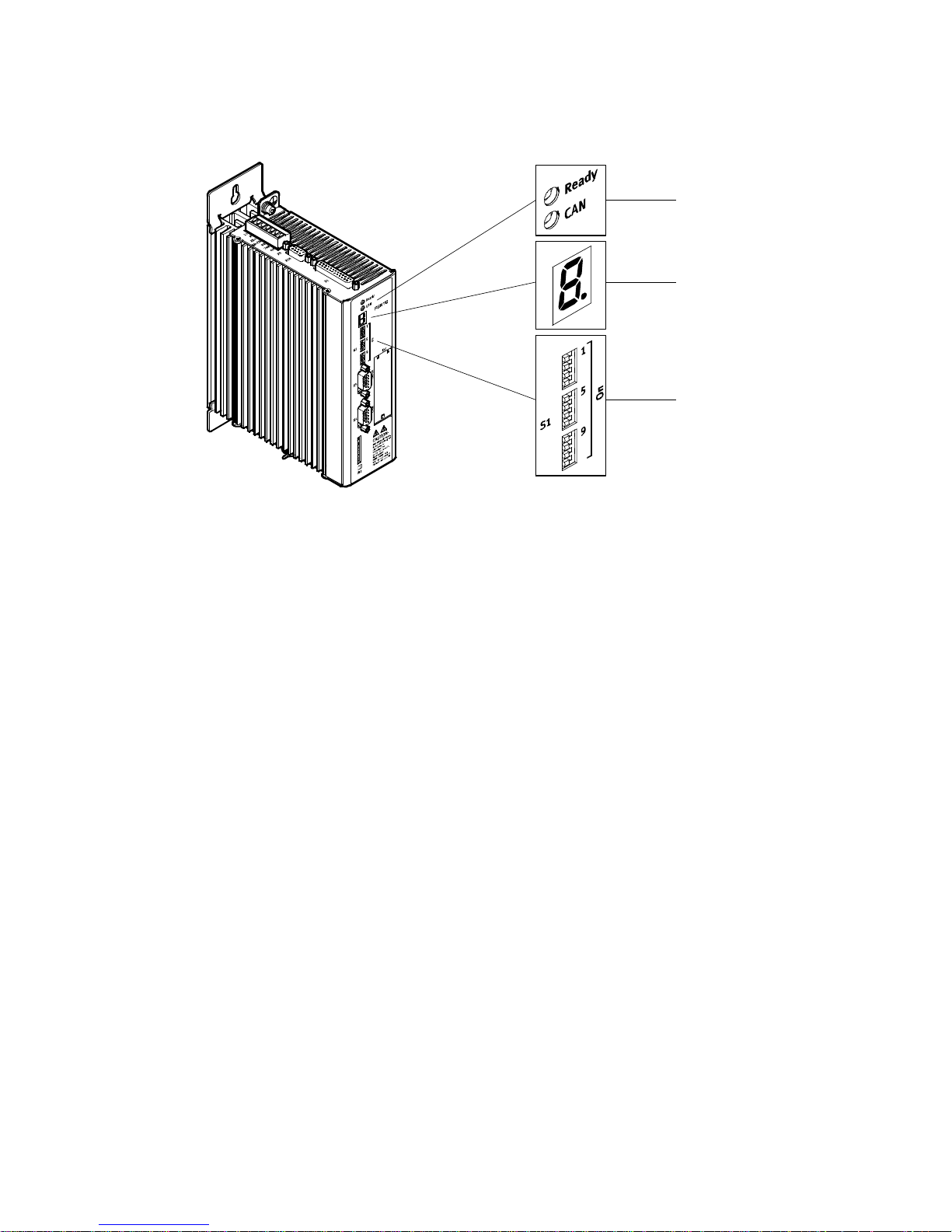
2.1.4 LED indicators, seven-segment displays and DIL switches
Fig. 2.4 Overview: LED indicators, seven-segment displays and DIL switches
1
2
3
22 Festo – GDCP-CMMS/D-FW-EN – 1404NH – English
Page 23
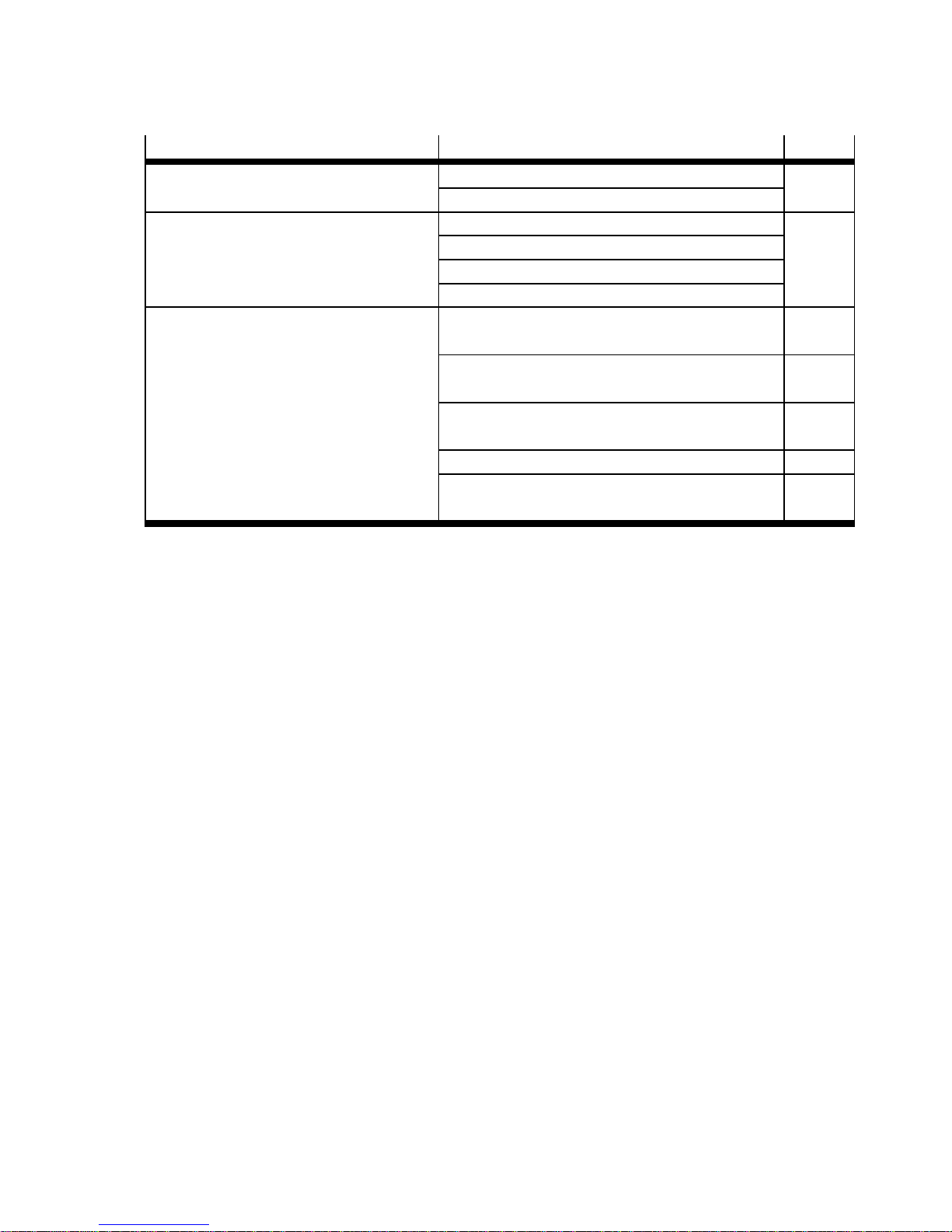
2Interfaces
Interface Function Page
1 LED indicators Ready (green) 212
CAN communication (yellow)
2 Seven-segment displays Error/warning messages 212
Operating modes
Bootloader
Safety function
3 DIL switch [S1] Fieldbus address/MAC-ID configuration
82
[S1.1…7]
Firmware download activation from the memory
83
card [S1.8]
Data rate configuration [ S 1.9…10]
83
(CAN bus/DeviceNet)
CAN bus activation [S1.11] 83
Terminating resistor activation [S1.12]
84
(CAN bus)
Tab. 2.4 Overview: LED indicators, seven-segment displays and DIL switches
Festo – GDCP-CMM S/D-FW-EN – 1404NH – English 23
Page 24
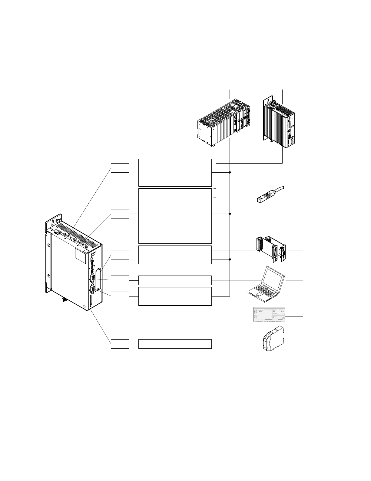
2Interfaces
2
3
2.2 Motor controller CMMS-ST-C8-7-G2
2.2.1 Control, sensor and safety function interfaces
1
X10
X1
EXT
X5
X4
A/#A/B/#B/N/#N
CLK/#CLK/DIR/#DIR
CW/#CW/CCW/#CCW
DIN0…13
DOUT0…3
AIN0/#AIN0
AMON0
CLK/#CLK/DIR/#DIR
CW/#CW/CCW/#CCW
DeviceNet
PROFIBUS DP
RS485
CANOpen
DriveBus
4
5
6
7
X3
Fig. 2.5 Overview: Control, sensor and safety function interfaces
24 Festo – GDCP-CMMS/D-FW-EN – 1404NH – English
STO
8
Page 25
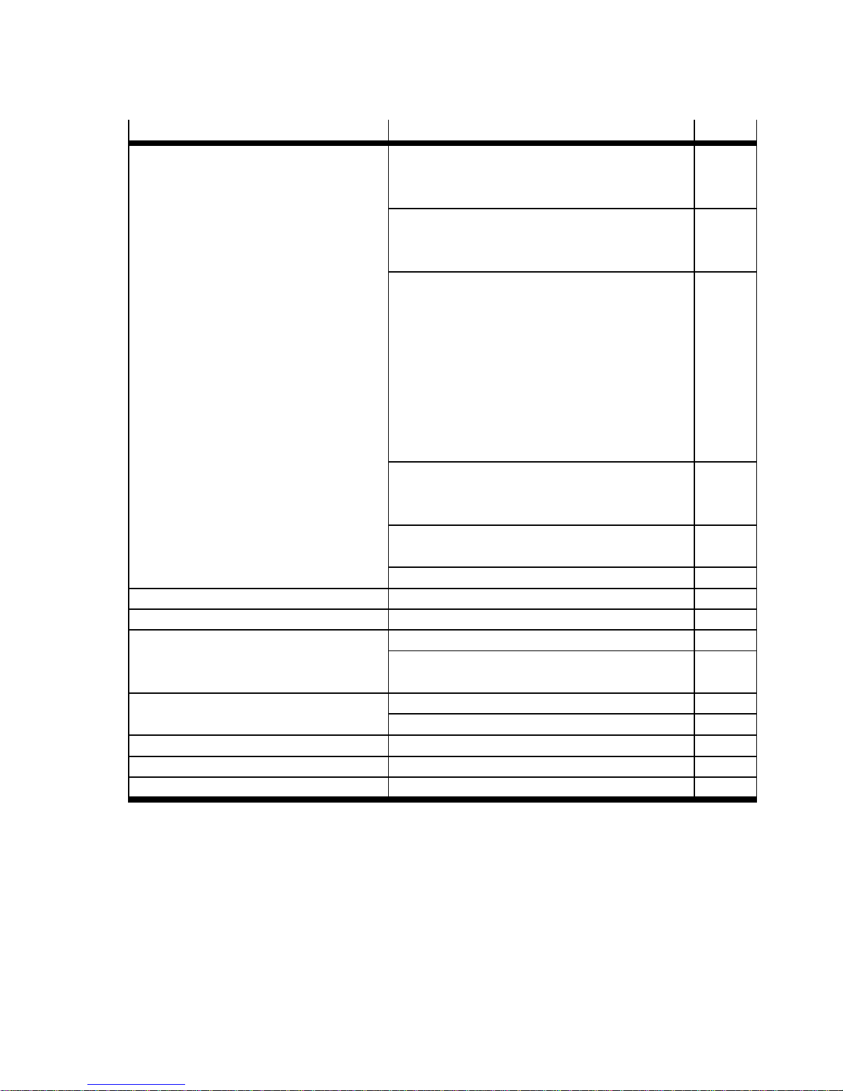
2Interfaces
Interface Function Page
1 Motor controller CMMS-ST-C8-7-G2 Digital interface [X1]
– Digital inputs (DIN0…13) 50
– Digital outputs (DOUT0…3) 50
Analogue interface [X1]
– Analogue inputs (AIN0/#AIN0) 65
– Analogue output (AMON0) 66
Synchronisation interfaces [X1][X10]
– Encoder inputs 67
– Encoder outputs 68
– Incremental signals
69
(A/#A/B/#B/N/#N)
– Pulse/direction signals [X10]
70
(CLK/#CLK/DIR/#DIR)
– Forward/reverse signals [X10]
71
(CW/#CW/CCW/#CCW)
CAN interface [X4]
–CANopen 72
–DriveBus 72
Slot [EXT]
– Interface module CAMC-... 5 72
RS485 interface [ X5] 240
2 Control Master device
3 Motor controller CMM... Master or slave device
4 Sensors Limit switches 77
Sequence control (N EXT1/2) 148/
149
5 Interface module CAMC-... DeviceNet (CAMC-DN) 72
PROFIBUS DP ( CAMC-PB) 72
6 PC Master device, RS485 interface
7 Festo Configuration Tool (FCT) Jog/individual step 172
8 Safety switching device Safety function STO (Safe Torque Off) 12
Tab. 2.5 Overview: Control, sensor and safety function interfaces
Festo – GDCP-CMM S/D-FW-EN – 1404NH – English 25
Page 26
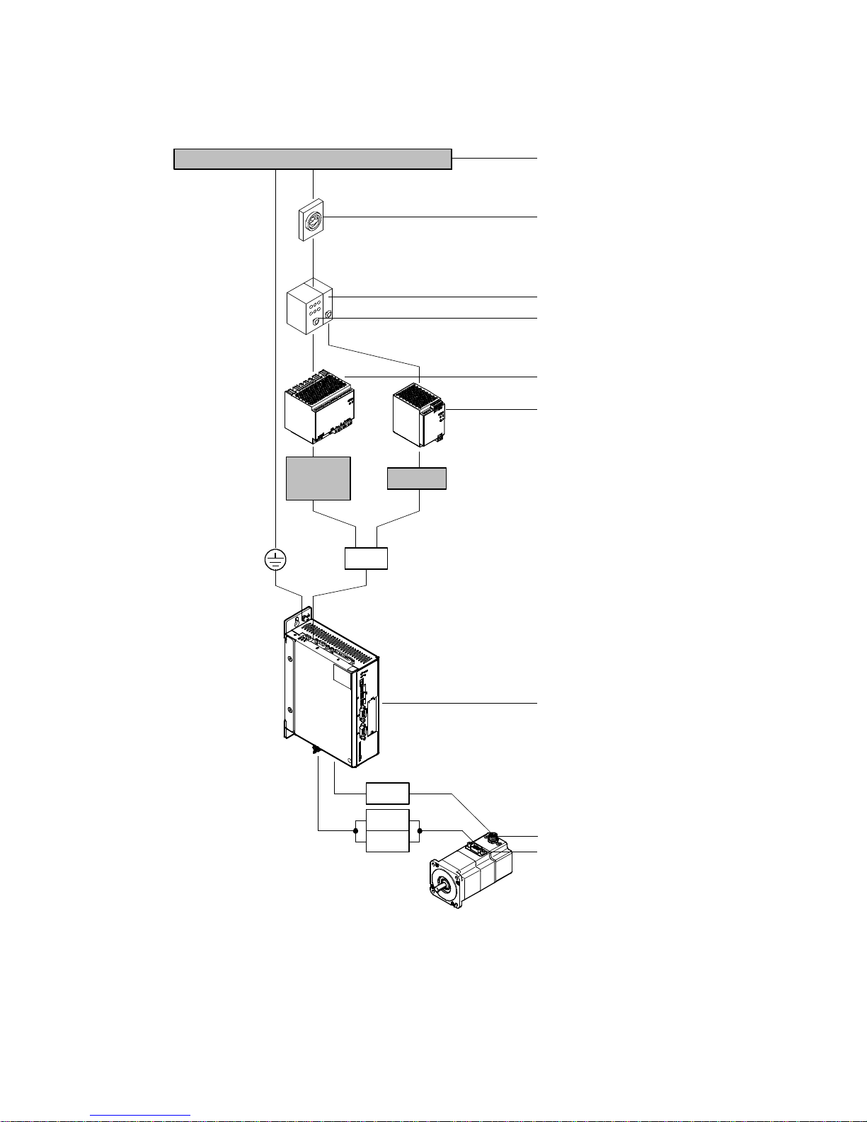
2Interfaces
2.2.2 Power supply, motor and motor encoder interfaces
1 x 110 … 230 V AC/3x400 … 500 V AC
Power ON/OFF
24 V DC/
48 V DC
24 V DC
X9
1)
1
2
3
4
5
6
1) Dependent on the power supply “power supply unit power section”
Fig. 2.6 Overview: Power supply, motor and motor encoder interfaces
26 Festo – GDCP-CMMS/D-FW-EN – 1404NH – English
X2
X6
GND
7
8
9
Page 27
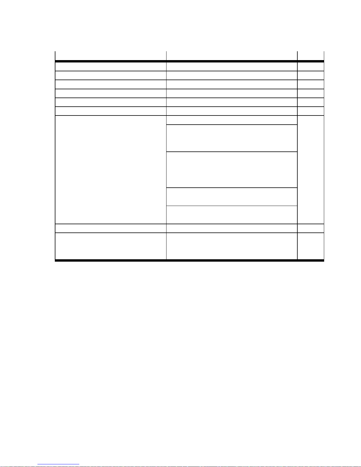
2Interfaces
Interface Function Page
1 Mains supply
2 Power switch
3 Fuse “control section” Application-dependent
4 Fuse “power section” Application-dependent
5 Power supply unit “power section” Output voltage: 24/48 V DC
6 Power supply unit “control section” Output voltage: 24 V DC
7 Motor controller CMMS-ST-C8-7-G2 Protective earthing “ (housing) 12
Power supply [X9]
– Power section: 24/48 V DC (ZK+/0 V)
– Control section: 24 V DC (24 V/0 V)
Motor interfaces [X6]
– Motor string (A/#A/B/#B)
– Holding brake (BR+/BR–)
– Motor temperature sensor (MT+/MT–)
Motor encoder [X2]
– Incremental signals (A/#A/B/#B/N/#N)
Terminal “motor cable screening GN D”
(connected with protective earthing “)
8 Motor encoder1)(closed loop) Incremental signals (A/#A/B/#B/N/#N) 12
9 Stepper motor EMMS-ST/MTR-ST – Motor string (A/#A/B/#B)
12
– Holding brake (BR+/BR–)
– Motor temperature sensor (MT+/MT–)
1) I f the stepper motor is configured without a motor encoder in the Festo Configuration Tool (FCT), the motor controller is automatic-
ally operated in an open control circuit (open loop).
Tab. 2.6 Overview: Power supply, motor and motor encoder interfaces
Festo – GDCP-CMM S/D-FW-EN – 1404NH – English 27
Page 28
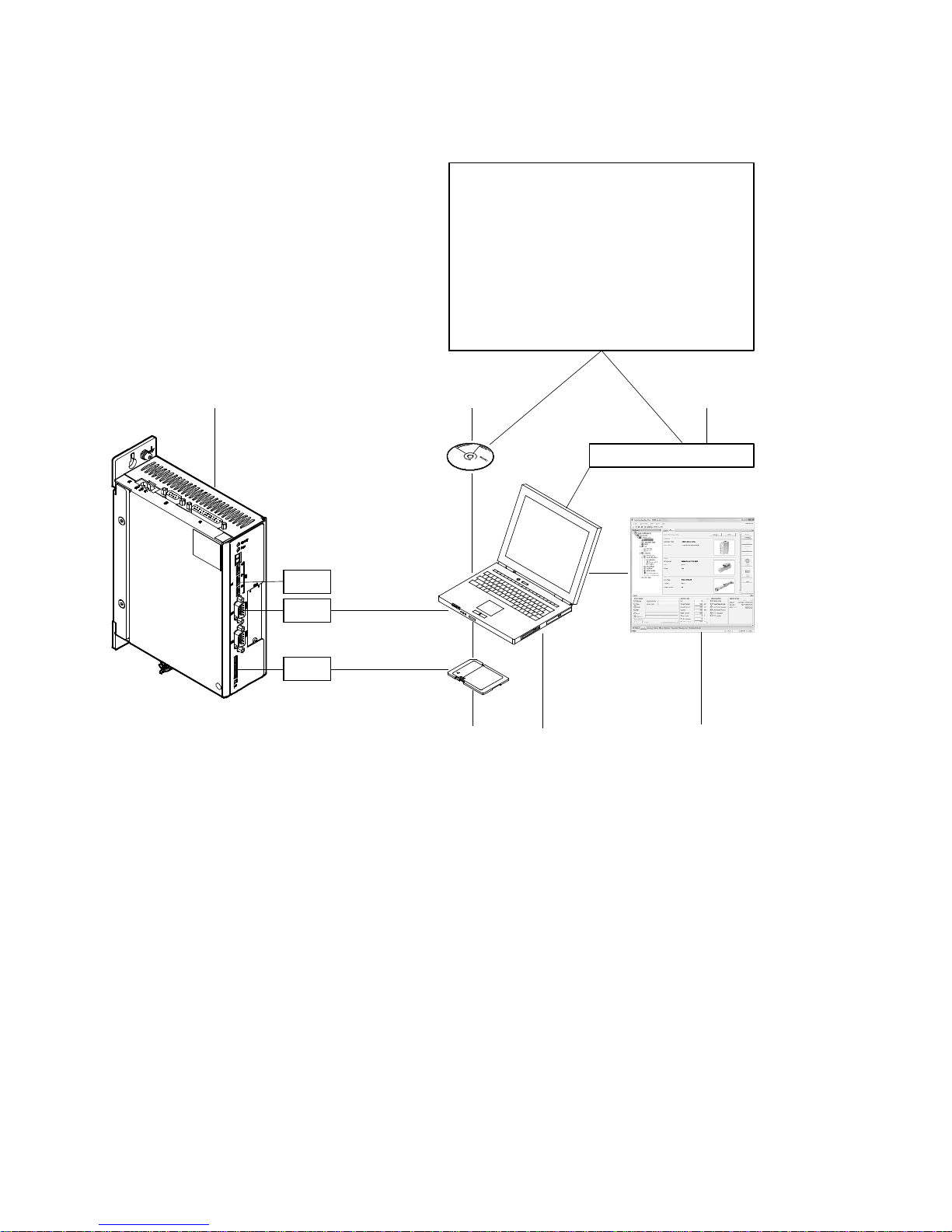
2Interfaces
2.2.3 Parameter/firmware interfaces
123
Festo Configuration Tool (FCT)
Framework/plug-in
Firmware files
Device-descriptive files
EDS/GSD
Function block files
CodeSys/Step7/RSLogix 5000
Documentation
www.festo.com/sp
S1.8
Download
X5
Upload
Read
M1
Write
Fig. 2.7 Overview: Parameter/firmware interfaces
56
4
28 Festo – GDCP-CMMS/D-FW-EN – 1404NH – English
Page 29
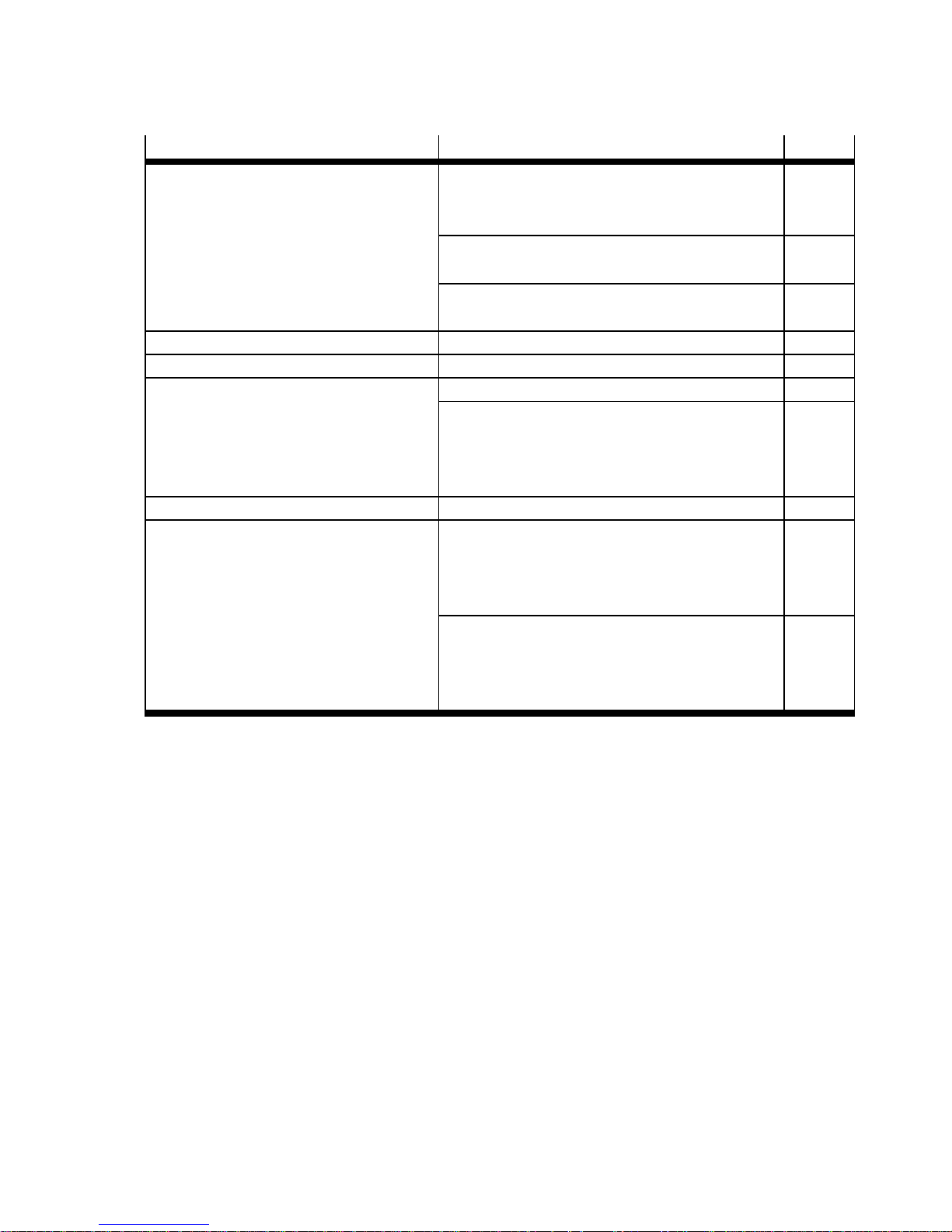
2Interfaces
Interface Function Page
1 Motor controller CMMS-ST-C8-7-G2 DIL switch [S1.8]
83
– Firmware download activation from the
memory card
RS232 interface [X5]
– Onlinedatainterface
235
Card slot [M1]
– Slot for memory card
2 CD-ROM Included in the scope of delivery
3 Internet Support Portal: www.festo.com/sp
4 Festo Configuration Tool (FCT) Parameterisation/configuration 79
Data transfer control
– Firmware file 86
– Device data (FCT) 89
– Parameter set data (motor controller) 92
5 PC Operating system “Windows ...”
6 Memory card – Supportedcardtype:
SD ( version 1 and 2)
– Supported file system:
FAT16 (max. 2 GB)
Data transfer control
Download firmware file (.S) 87
Read parameter file (.DCO) 93
Write parameter file (. DCO) 93
Tab. 2.7 Overview: Parameter/firmware interfaces
Festo – GDCP-CMM S/D-FW-EN – 1404NH – English 29
Page 30
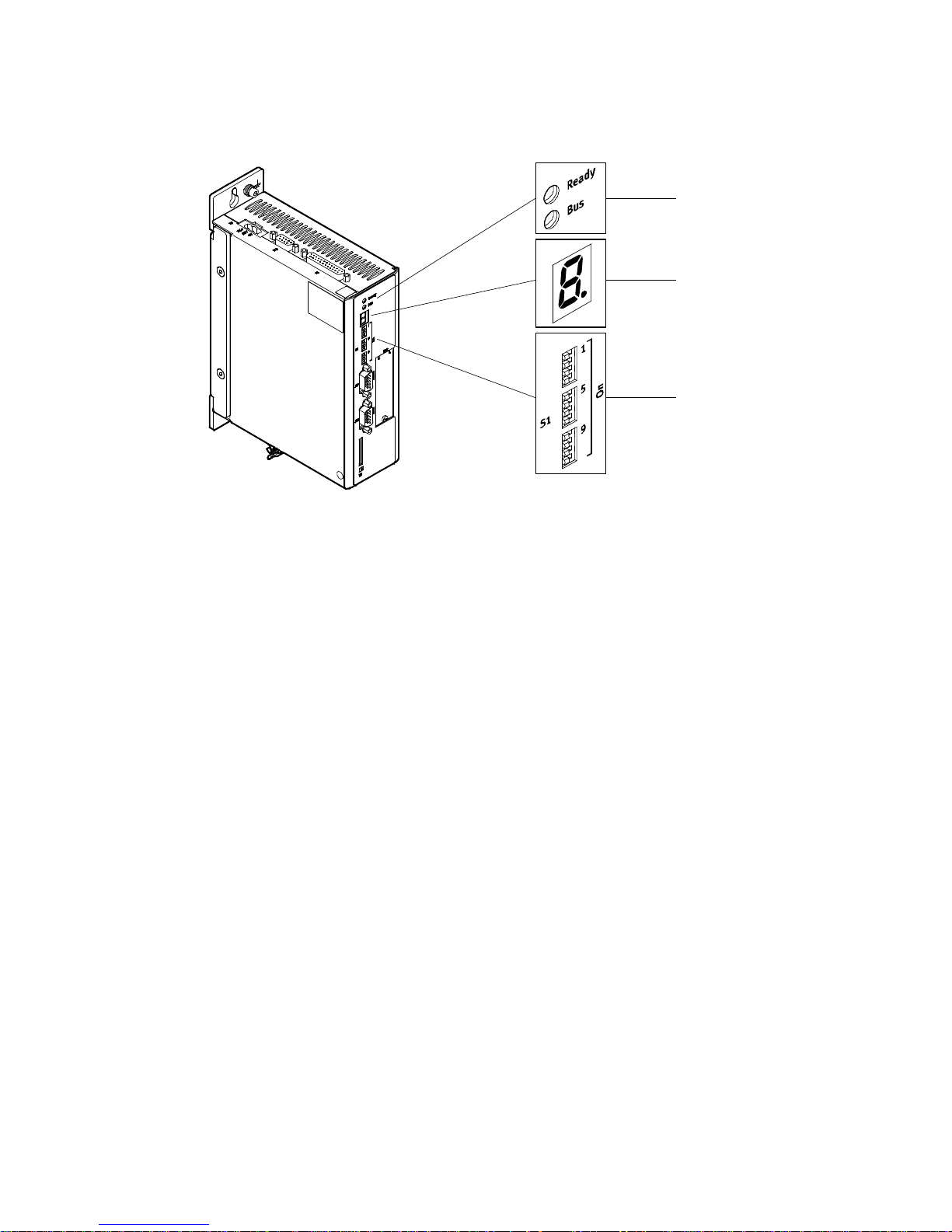
2Interfaces
2.2.4 LED indicators, seven-segment displays and DIL switches
Fig. 2.8 Overview: LED indicators, seven-segment displays and DIL switches
1
2
3
30 Festo – GDCP-CMMS/D-FW-EN – 1404NH – English
Page 31
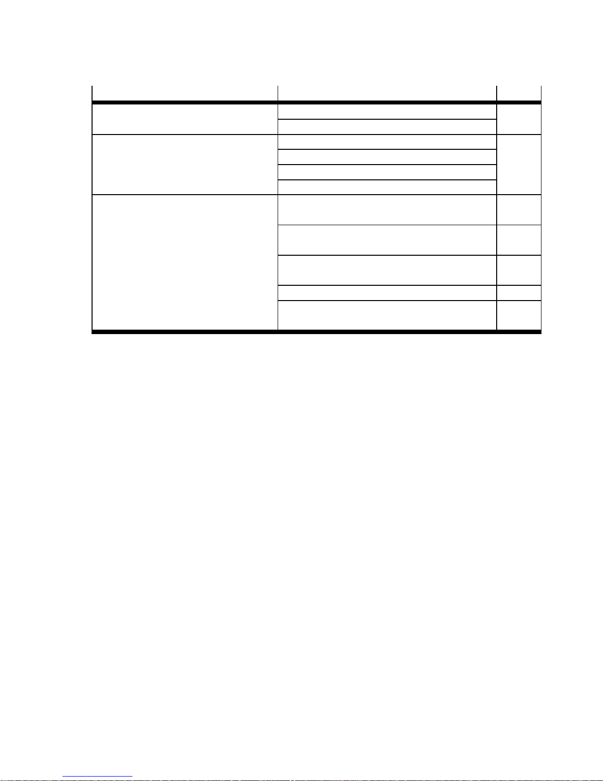
2Interfaces
Interface Function Page
1 LED indicators Ready (green) 212
BUS communication (yellow)
2 Seven-segment displays Error/warning messages 212
Operating modes
Bootloader
Safety function
3 DIL switch [S1] Fieldbus address/MAC-ID configuration
82
[S1.1…7]
Firmware download activation from the memory
83
card [S1.8]
Data rate configuration [ S 1.9…10]
83
(CAN bus/DeviceNet)
CAN bus activation [S1.11] 83
Terminating resistor activation [S1.12]
84
(CAN bus)
Tab. 2.8 Overview: LED indicators, seven-segment displays and DIL switches
Festo – GDCP-CMM S/D-FW-EN – 1404NH – English 31
Page 32
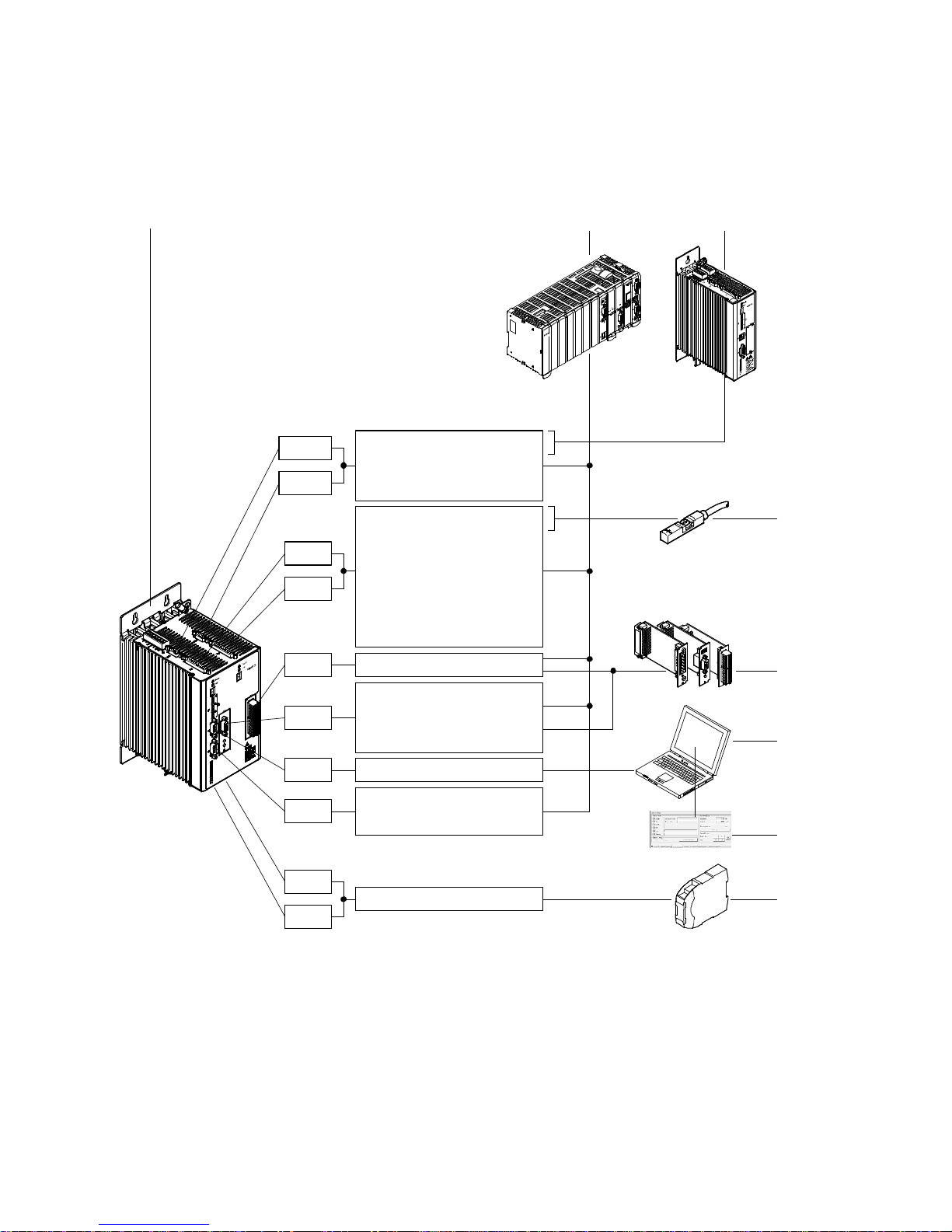
2Interfaces
2.3 Motor controller CMMD-AS-C8-3A
2.3.1 Control, sensor and safety function interfaces
1
X10.1
X10.2
X1.1
X1.2
EXT2
EXT1
A/#A/B/#B/N/#N
CLK/#CLK/DIR/#DIR
CW/#CW/CCW/#CCW
DIN0…13
DOUT0…3
AIN0/#AIN0
AMON0
CLK/#CLK/DIR/#DIR
CW/#CW/CCW/#CCW
DOUT_EXT2.0…7
DOUT_EXT1.0…7
DeviceNet
PROFIBUS DP
2
3
4
5
6
X5
X4
X3.2
X3.1
Fig. 2.9 Overview: Control, sensor and safety function interfaces
32 Festo – GDCP-CMMS/D-FW-EN – 1404NH – English
RS485
CANOpen
DriveBus
STO
7
8
Page 33
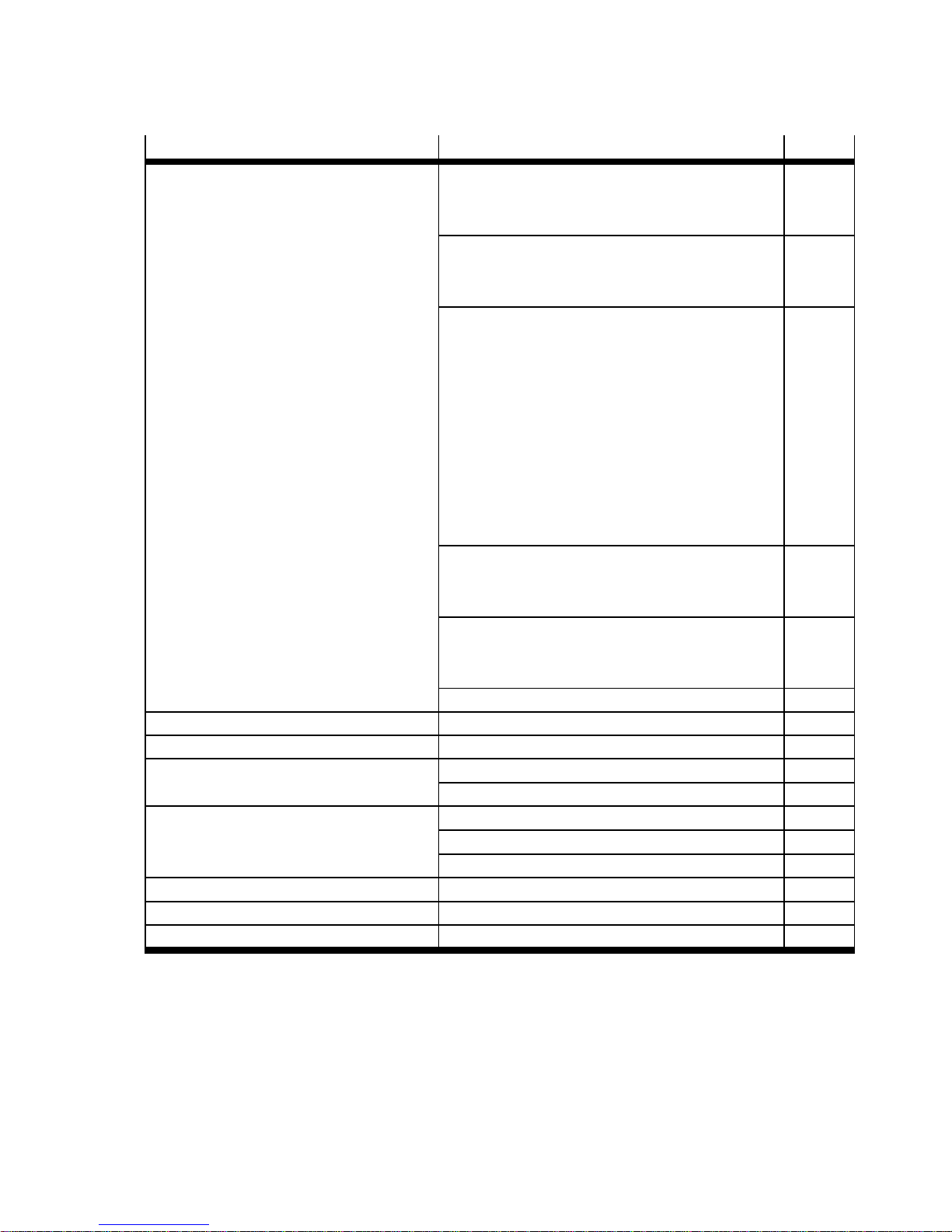
2Interfaces
Interface Function Page
1 Motor controller CMMD-AS-C8-3A Digital interface [X1.1/X1.2]
– Digital inputs (DIN0…13) 50
– Digital outputs (DOUT0…3) 50
Analogue interface [X1.1/X1.2]
– Analogue inputs (AIN0/#AIN0) 65
– Analogue output (AMON0) 66
Synchronisation interfaces
[X1.1/X1.2][X10.1/X10.2]
– Encoder inputs 67
– Encoder outputs 68
– Incremental signals
69
(A/#A/B/#B/N/#N)
– Pulse/direction signals [X10.1/X10.2]
70
(CLK/#CLK/DIR/#DIR)
– Forward/reverse signals [X10.1/X10.2]
71
(CW/#CW/CCW/#CCW)
CAN interface [X4]
–CANopen 72
–DriveBus 72
Slots [EXT1/2]
– Interface module CAMC-... 5 72
– Input/output module CAMC-D-... 5
RS485 interface [ X5] 240
2 Control Master device
3 Motor controller CMM... Master or slave device
4 Sensors Limit switches 77
Sequence control (N EXT1/2) 148/
5 Interface module CAMC-...
Input/output module CAMC-D-...
DeviceNet (CAMC-DN) 72
PROFIBUS DP ( CAMC-PB) 72
Digital inputs/outputs (CAMC-D-8E8A)
1)
49
6 PC Master device
7 Festo Configuration Tool (FCT) Jog/individual step 172
8 Safety switching device Safety function STO (Safe Torque Off) 12
1) Digital inputs cannot be used.
Tab. 2.9 Control, sensor and safety function interfaces
Festo – GDCP-CMM S/D-FW-EN – 1404NH – English 33
Page 34
2Interfaces
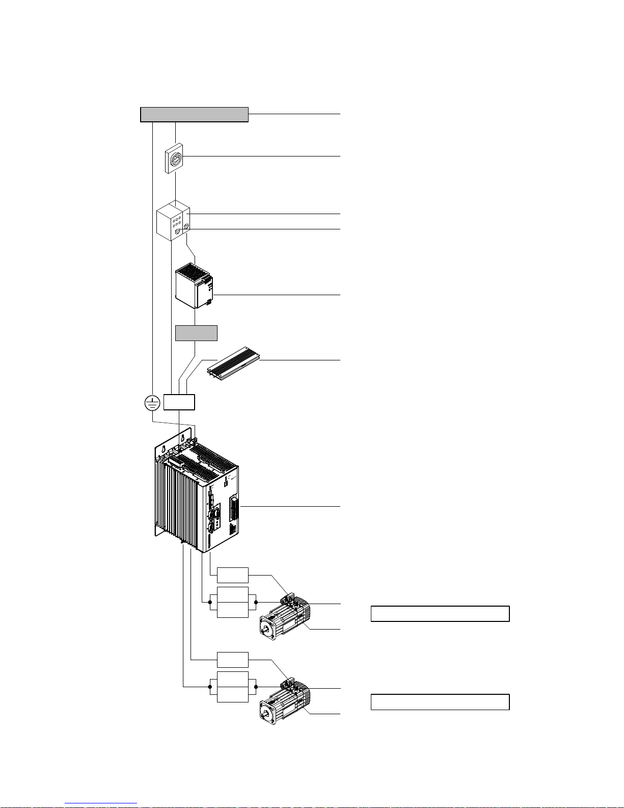
2.3.2 Power supply, motor and motor encoder interfaces
1 x 110 … 230 V AC
Power ON/OFF
24 V DC
X9
1
2
3
4
5
6
Fig. 2.10 Overview: Power supply, motor and motor encoder interfaces
34 Festo – GDCP-CMMS/D-FW-EN – 1404NH – English
X2.2
X6.2
GND
X2.1
X6.1
GND
7
8
Axis string 2
9
8
Axis string 1
9
Page 35
2Interfaces
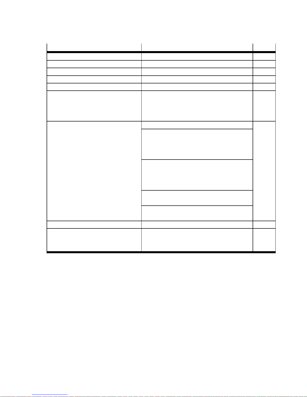
Interface Function Page
1 Mains supply
2 Power switch
3 Fuse “control section” Application-dependent
4 Fuse “power section” Application-dependent
5 Power supply unit “control section” Output voltage: 24 V DC
6 External braking resistor
(optional)
–Resistance≥ 100 Ω
– Rated output ≤ 100 W
– Pulse power ≤ 1600 W
– Nominal voltage 400 V AC
7 Motor controller CMMD-AS-C8-3A Protective earthing “ (housing) 12
Power supply [X9]
– Power section: 230 V AC (L1/N/PE)
– Control section: 24 V DC (24 V/0 V)
– External braking resistor (ZK+/BR-CH)
Motor interfaces [X6.1/X6.2]
– Motor (U/V/W/PE)
– Holding brake (BR+/BR–)
– Motor temperature sensor (MT+/MT–)
Motor encoder [X2.1/X2.2]
–EnDatinterface
Terminal “motor cable screening GN D”
(connected with protective earthing “)
8 Motor encoder (closed loop) EnDat interface 12
9 Servo motor EMMS-AS – Motor (U/V/W/PE)
12
– Holding brake (BR+/BR–)
– Motor temperature sensor (MT+/MT–)
Tab. 2.10 Overview: Power supply, motor and motor encoder interfaces
Festo – GDCP-CMM S/D-FW-EN – 1404NH – English 35
Page 36
2Interfaces
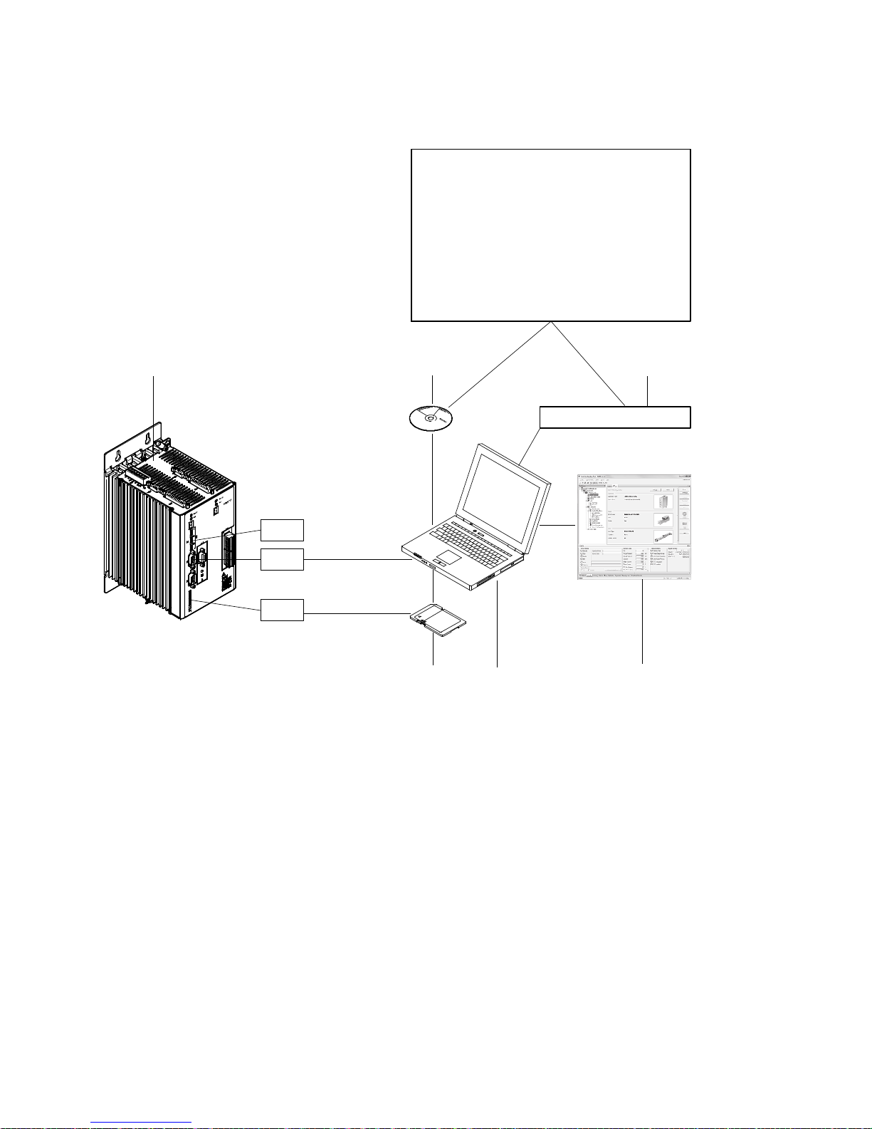
2.3.3 Parameter/firmware interfaces
Festo Configuration Tool (FCT)
Framework/plug-in
Firmware files
Device-descriptive files
EDS/GSD
Function block files
CodeSys/Step7/RSLogix 5000
Documentation
1
S1.8
Download
X5
Upload
Read
M1
Write
Fig. 2.11 Overview: Parameter/firmware interfaces
23
www.festo.com/sp
56
4
36 Festo – GDCP-CMMS/D-FW-EN – 1404NH – English
Page 37
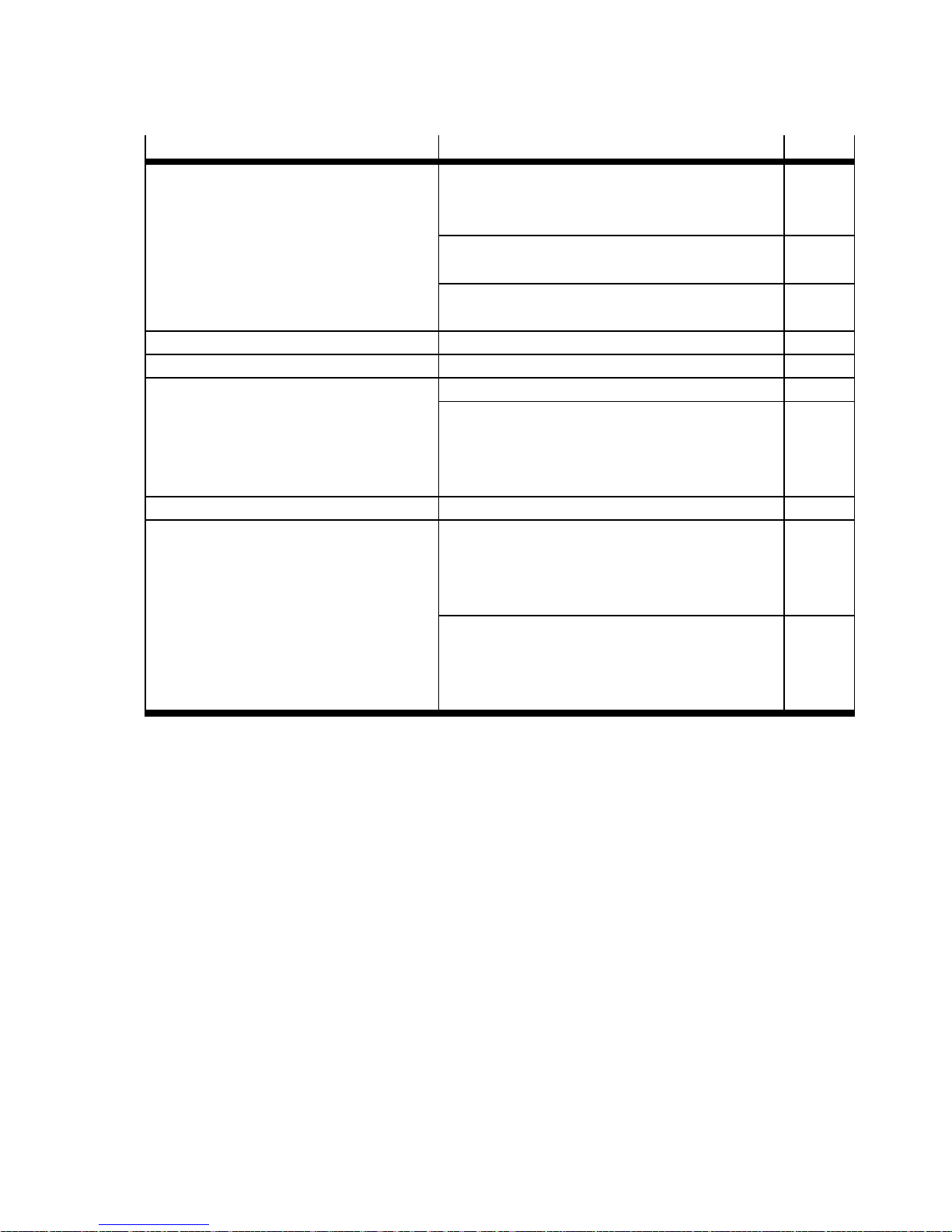
2Interfaces
Interface Function Page
1 Motor controller CMMD-AS-C8-3A DIL switch [S1.8]
83
– Firmware download activation from the
memory card
RS232 interface [X5]
– Onlinedatainterface
235
Card slot [M1]
– Slot for memory card
2 CD-ROM Included in the scope of delivery
3 Internet Support Portal: www.festo.com/sp
4 Festo Configuration Tool (FCT) Parameterisation/configuration 79
Data transfer control
– Firmware file 86
– Device data (FCT) 89
– Parameter set data (motor controller) 92
5 PC Operating system “Windows ...”
6 Memory card – Supportedcardtype:
SD ( version 1 and 2)
– Supported file system:
FAT16 (max. 2 GB)
Data transfer control
Download firmware file (.S) 87
Read parameter file (.DCO) 93
Write parameter file (. DCO) 93
Tab. 2.11 Overview: Parameter/firmware interfaces
Festo – GDCP-CMM S/D-FW-EN – 1404NH – English 37
Page 38
2Interfaces
2.3.4 LED indicators, seven-segment displays and DIL switches
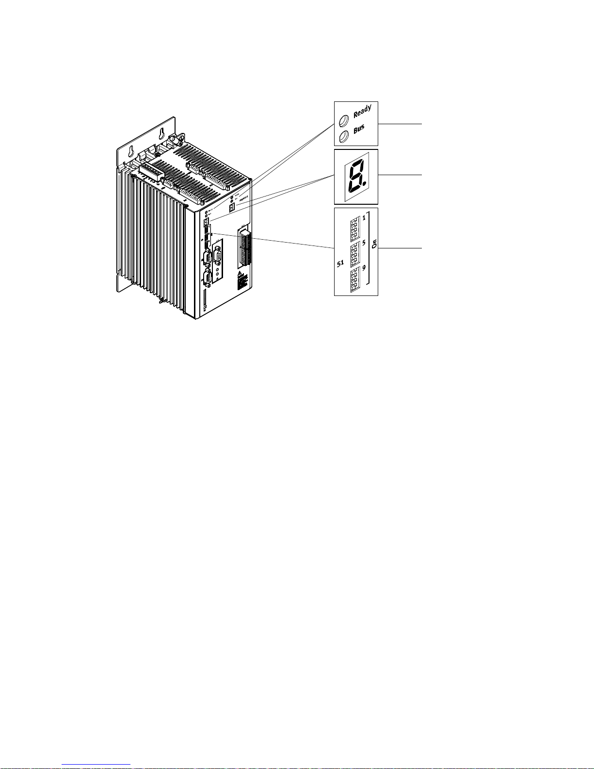
Fig. 2.12 Overview: LED indicators, seven-segment displays and DIL switches
1
2
3
38 Festo – GDCP-CMMS/D-FW-EN – 1404NH – English
Page 39
2Interfaces
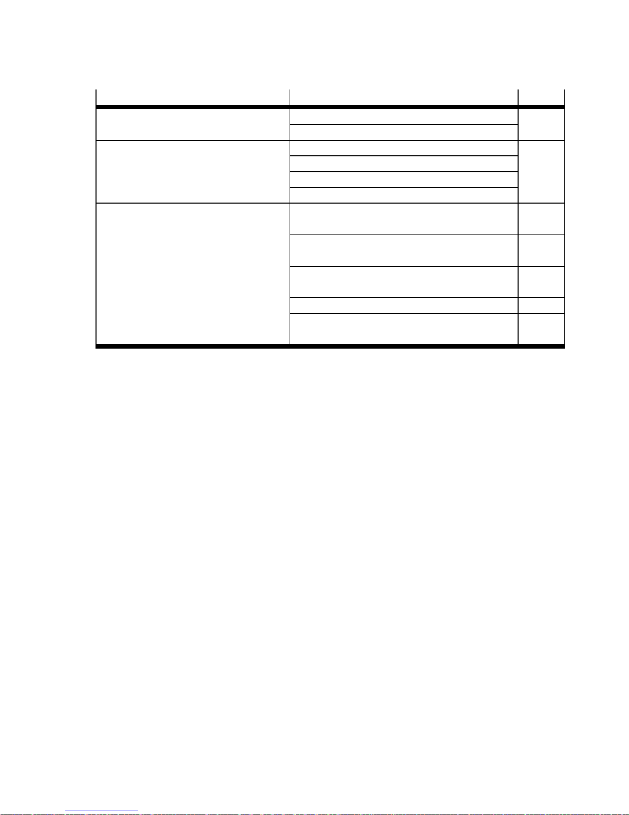
Interface Function Page
1 LED indicators Ready (green) 212
BUS communication (yellow)
2 Seven-segment displays Error/warning messages 212
Operating modes
Bootloader
Safety function
3 DIL switch [S1] Fieldbus address/MAC-ID configuration
82
[S1.1…7]
Firmware download activation from the memory
83
card [S1.8]
Data rate configuration [ S 1.9…10]
83
(CAN bus/DeviceNet)
CAN bus activation [S1.11] 83
Terminating resistor activation [S1.12]
84
(CAN bus)
Tab. 2.12 Overview: LED indicators, seven-segment displays and DIL switches
Festo – GDCP-CMM S/D-FW-EN – 1404NH – English 39
Page 40
2Interfaces
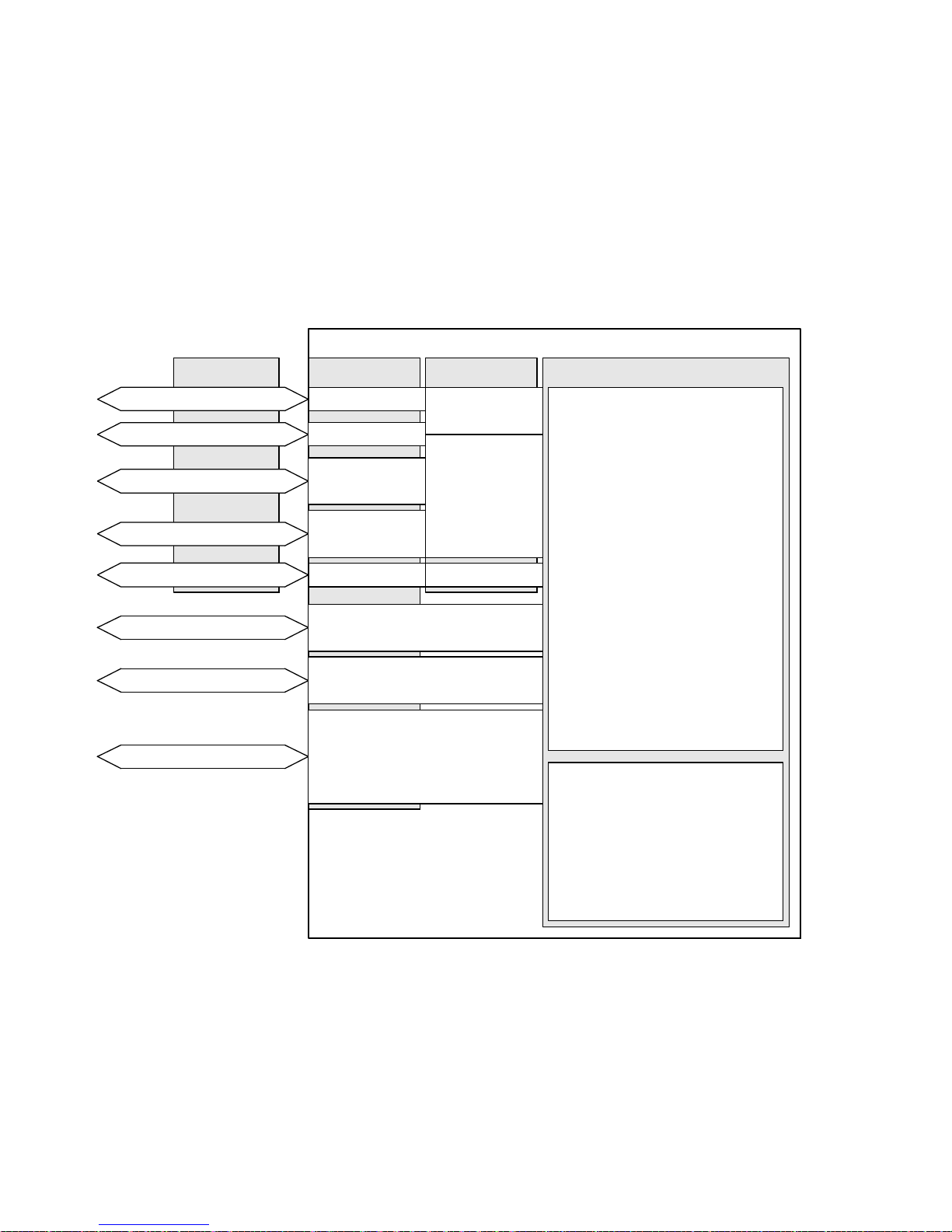
2.4 Control interfaces – operating modes – operational functions
The motor controller can be operated through a number of interfaces. Various operating modes and
operational functions are available, dependent on the selected control interface and the device profile
(only for fieldbus). The control interfaces are permanently assigned to the connections. You can take
the possible combinations from the following overviews.
2.4.1 Overview: Control interfaces/c onnections/device profiles/
operating modes/operational functions
Control interfaces
Fieldbus
DriveBus
CANOpen
PROFIBUS DP
DeviceNet
RS485
Digital I/O modules
Analogue input/output
Synchronisation
1)
CMMS/CMMD
Connections
X4
X4
EXT (CMMS)
EXT1 (CMMD)
EXT (CMMS)
EXT1 (CMMD)
X5
X12)(CMMS)
X1.1/X1.2
2)
(CMMD)
X13)(CMMS)
X1.1/X1.2
3)
(CMMD)
X12)(CMMS)
4)
X10
(CMMS)
X1.1/X1.2
X10.1/X10.2
2)
(CMMD)
4)
Device profiles
CiA402
FHPP
CI
5)
6)
7)
(CMMD)
Operating modes/functions
Operating modes:
– Positioning mode
•Directmode
• Individual record mode
• Record linking mode
• Interpolated positioning
mode
• Homing mode
•Jogmode
• Teach mode
– Speed mode
– Force/torque mode
– Synchronisation
Operational functions:
– Encoder emulation
– Flying measurement
– Analogue monitor
– Endless po sit io ning
1) Encoder input for the “synchronisation” operating mode
2) HTL signal (high transistor logic): High signal = 24 V
3) Analogue input signal: ± 10 V,
analogue output signal: + 10 V
Fig. 2.13 Overview: Control interfaces/connections/device profiles/operating modes/operational
functions
40 Festo – GDCP-CMMS/D-FW-EN – 1404N H – English
4) TTL signal (transistor-transistor logic): High signal = 5 V
5) CANopen device profile CiA 402
6) Festo handling and positioning profile (FHPP)
7) CAN-Interpreter
Page 41
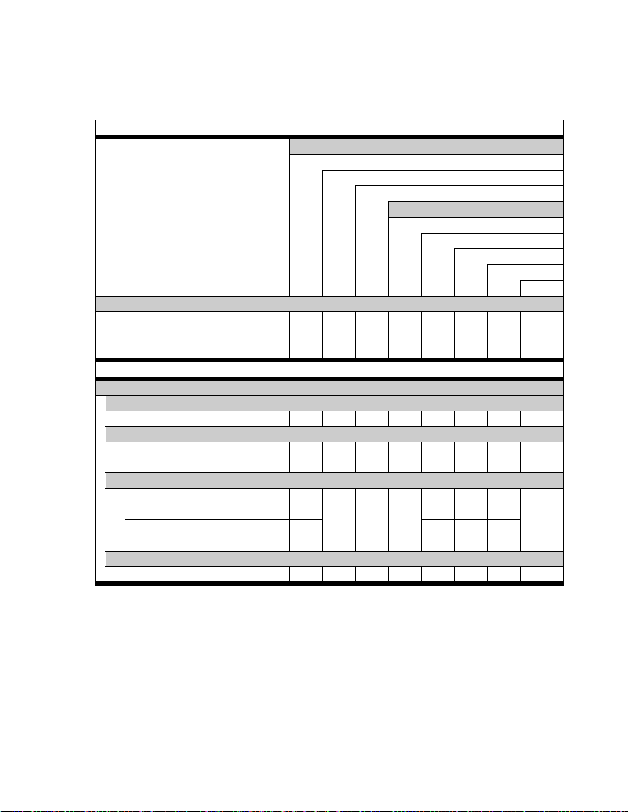
2Interfaces
2.4.2 Positioning mode: Direct mode, individual record mode,
record linking mode and interpolated positioning mode
Control interfaces page 46
Inputs/outputs
Digital inputs/outputs DIN/DOUT, 24 V
Analogue input AIN, ± 10 V
Synchronisation (encoder input), 5 V
Fieldbus
DriveBus (Motion Control)
Device profile
– C = CiA 402 (CANopen)
C F/C F F CI
– CI = CA N-Interpreter (CiA 402, SDO)
– F = F HPP (Festo)
CANOpen
PROFIBUS DP
DeviceNet
RS485
Operating modes
Positioning mode (position control) page 112
Direct mode page 115
Direct application F/C F F CI
Individual record mode page 119
Record selection
DIN F F F
(Positioning record 1…63)
Record linking mode page 136
Record selection
DIN
(Positioning record 1…7)
Record selection
F F F
(Positioning record 1…63)
Interpolated positioning mode page 152
Direct application C C
Tab. 2.13 Overview: Positioning mode “direct mode, individual record mode, record linking mode and
interpolated positioning mode”
Festo – GDCP-CMM S/D-FW-EN – 1404NH – English 41
Page 42
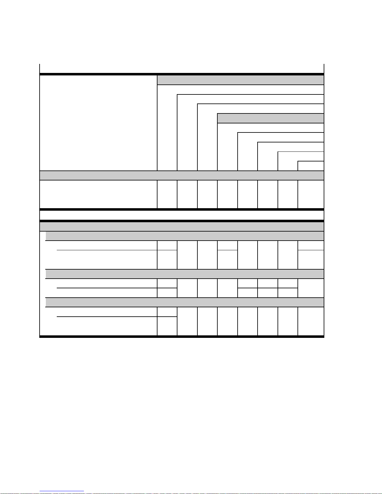
2Interfaces
2.4.3 Positioning mode: Homing mode/jog mode/teach mode
Control interfaces page 46
Inputs/outputs
Digital inputs/outputs DIN/DOUT, 24 V
Analogue input AIN, ± 10 V
Synchronisation (encoder input), 5 V
Fieldbus
DriveBus (Motion Control)
Device profile
– C = CiA 402 (CANopen)
C F/C F F CI
– CI = CA N-Interpreter (CiA 402, SDO)
– F = F HPP (Festo)
CANOpen
PROFIBUS DP
DeviceNet
RS485
Operating modes
Positioning mode (position control) page 112
Homing mode/homing page 154
Direct application C F/C F F CI
Record selection
DIN
(Positioning record 0)
Jog mode page 171
Direct application F F F
Digital inputs DIN
Teach mode page 177
Direct application F F F
Record selection
DIN
(Positioning record 1…63)
Tab. 2.14 Overview: Positioning mode “homing mode/jog mode/teach mode”
42 Festo – GDCP-CMMS/D-FW-EN – 1404N H – English
Page 43
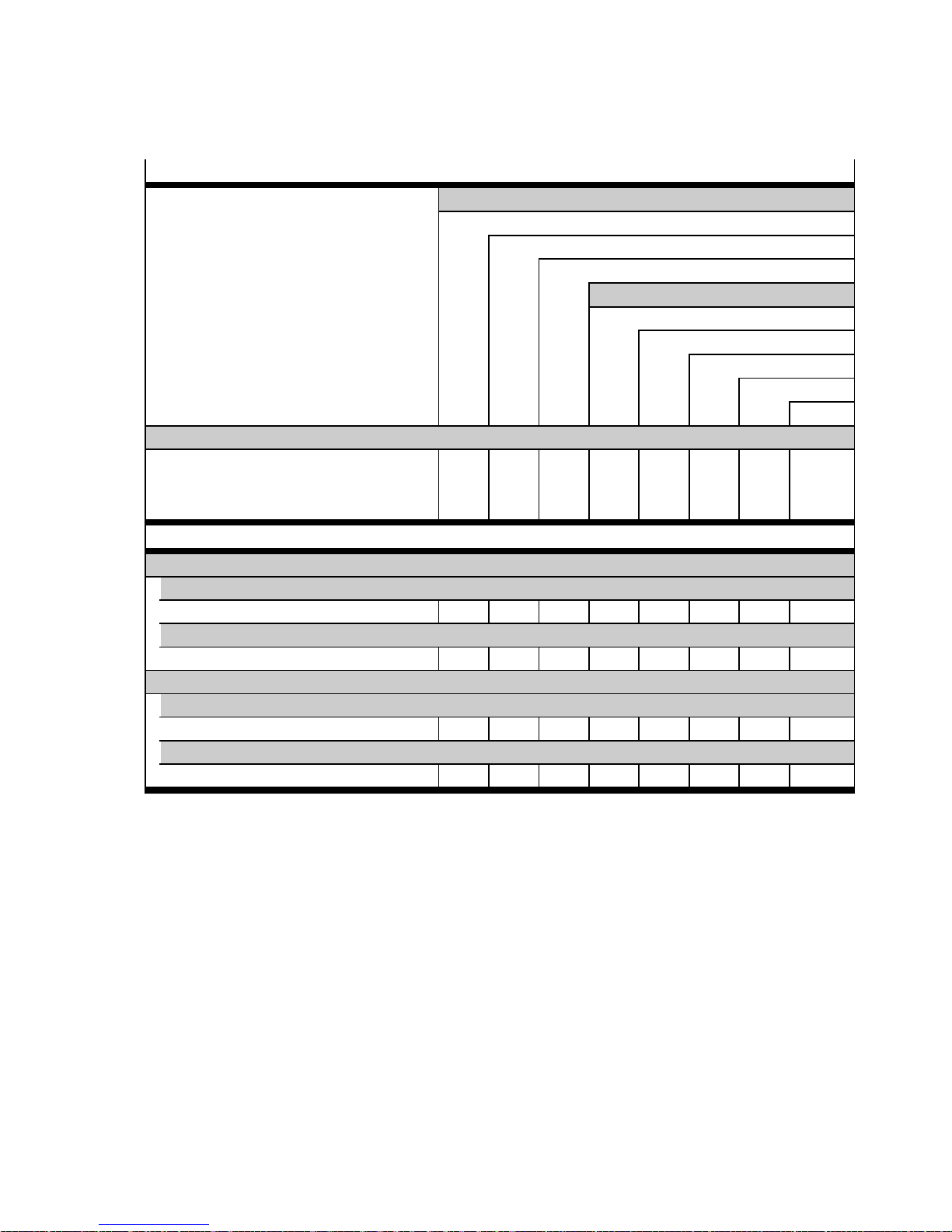
2Interfaces
2.4.4 Speed mode, force mode and torque mode
Control interfaces page 46
Inputs/outputs
Digital inputs/outputs DIN/DOUT, 24 V
Analogue input AIN, ± 10 V
Device profile
– C = CiA 402 (CANopen)
– CI = CA N-Interpreter (CiA 402, SDO)
– F = F HPP (Festo)
Synchronisation (encoder input), 5 V
Fieldbus
DriveBus (Motion Control)
CANOpen
PROFIBUS DP
DeviceNet
RS485
C F/C F F CI
Operating modes
Speed mode (speed adjustment) page 182
Direct mode
Direct application F/C F F CI
Analogue setpoint value
Analogue input AIN
Force mode1)/torque mode2)(current control) page 187
Direct mode
Direct application F/C F F CI
Analogue setpoint value
Analogue input AIN
1) Only for configuration “linear axis” active.
2) Only for configuration “rotative axis” active.
Tab. 2.15 Overview: Speed mode, force mode and torque mode
Festo – GDCP-CMM S/D-FW-EN – 1404NH – English 43
Page 44
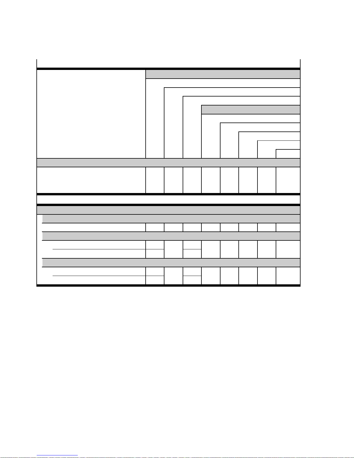
2Interfaces
2.4.5 Synchronisation
Control interfaces page 46
Device profile
– C = CiA 402 (CANopen)
– CI = CA N-Interpreter (CiA 402, SDO)
– F = F HPP (Festo)
Inputs/outputs
Digital inputs/outputs DIN/DOUT, 24 V
Analogue input AIN, ± 10 V
Synchronisation (encoder input), 5 V
Fieldbus
DriveBus (Motion Control)
CANOpen
PROFIBUS DP
DeviceNet
RS485
C F/C F F CI
Operating mode
Synchronisation (position control) page 192
Incremental signals (A/#A/B/#B/N/#N)
Incremental inputs IN
Pulse/direction signals (CLK/#CLK/DIR/#DIR)
Incremental inputs IN
Digital inputs DIN
Forward/reverse signals (CW/#CW/CCW/#CCW)
Incremental inputs IN
Digital inputs DIN
Tab. 2.16 Overview: Synchronisation
44 Festo – GDCP-CMMS/D-FW-EN – 1404NH – English
Page 45
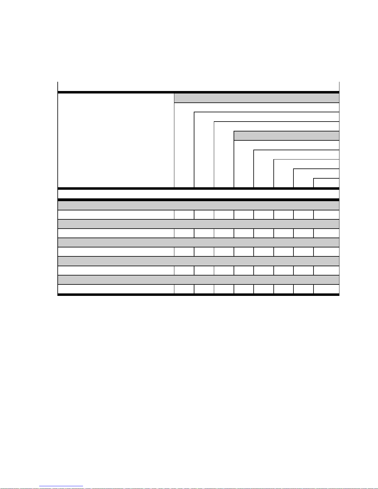
2Interfaces
2.4.6 Operational functions: Encoder emulation, flying measurement,
analogue monitor and endless positioning
Control interfaces page 46
Inputs/outputs
Digital inputs/outputs DIN/DOUT, 24 V
Analogue input AIN, ± 10 V
Synchronisation (encoder input), 5 V
Fieldbus
DriveBus (Motion Control)
CANOpen
Operational functions
Encoder emulation page 198
Incremental outputs yes yes no yes yes yes yes yes
Flying measurement page 200
Digital input no no no yes yes yes yes yes
Analogue monitor (AMON0) [0…10 V] page 202
Analogue output yes yes yes yes yes yes yes yes
Endless positioning page 205
yes yes yes yes yes yes yes yes
Resonance filter (only for motor controller CMMS-ST-C8-7-G2) page 207
yes yes yes yes yes yes yes yes
PROFIBUS DP
DeviceNet
RS485
Tab. 2.17 Operational functions: Encoder emulation, flying measurement, analogue monitor
and endless positioning
Festo – GDCP-CMM S/D-FW-EN – 1404NH – English 45
Page 46
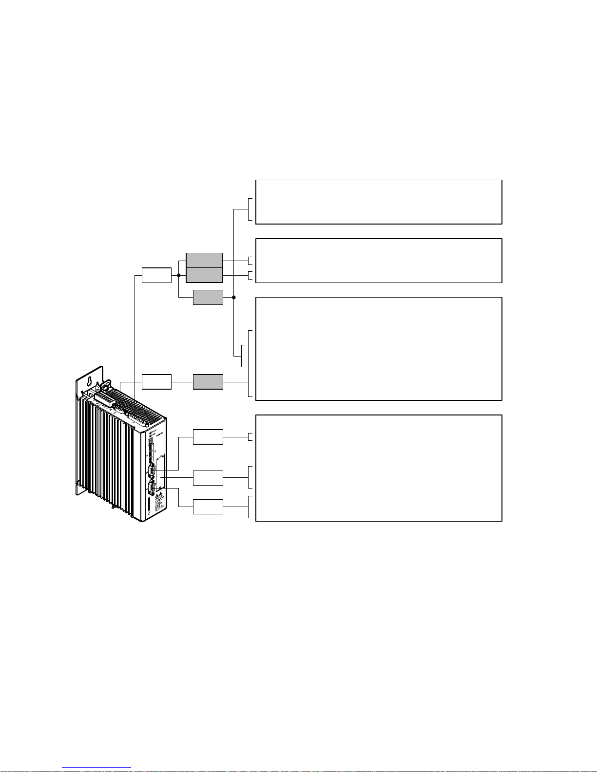
3 Control interfaces
3 Control interfaces
3.1 Digital, analogue, synchronisation and fieldbus interfaces
3.1.1 Motor controller CMMS-AS-C4-3A-G2
Digital interfaces:
– Digital inputs DIN0…13
– Digital outputs DOUT0…3
Analogue interfaces:
– Analogue inputs AIN0/#AIN0
– Analogue output AMON0
Synchronisation interfaces:
Encoder input:
– Incremental signals A/#A/B/#B/N/#N
– Pulse/direction signals CLK/#CLK/DIR/#DIR
– Forward/reverse signals CW/#CW/CCW/#CCW
Encoder output:
– Incremental signals A/#A/B/#B/N/#N
X1
X10
±10V
0…10 V
24 V
2)
5V
1)
Fieldbus interfaces:
X5
EXT
X4
1) HTL signal (high transistor logic): High signal = 24 V
2) TTL signal (transistor-transistor logic): High signal = 5 V
3) Interface module CAMC-... (optional)
–RS485
– DeviceNet
–PROFIBUSDP
3)
3)
–CANopen
–DriveBus
Fig. 3.1 Overview: Digital, analogue, synchronisation and fieldbus interfaces
46 Festo – GDCP-CMMS/D-FW-EN – 1404N H – English
Page 47
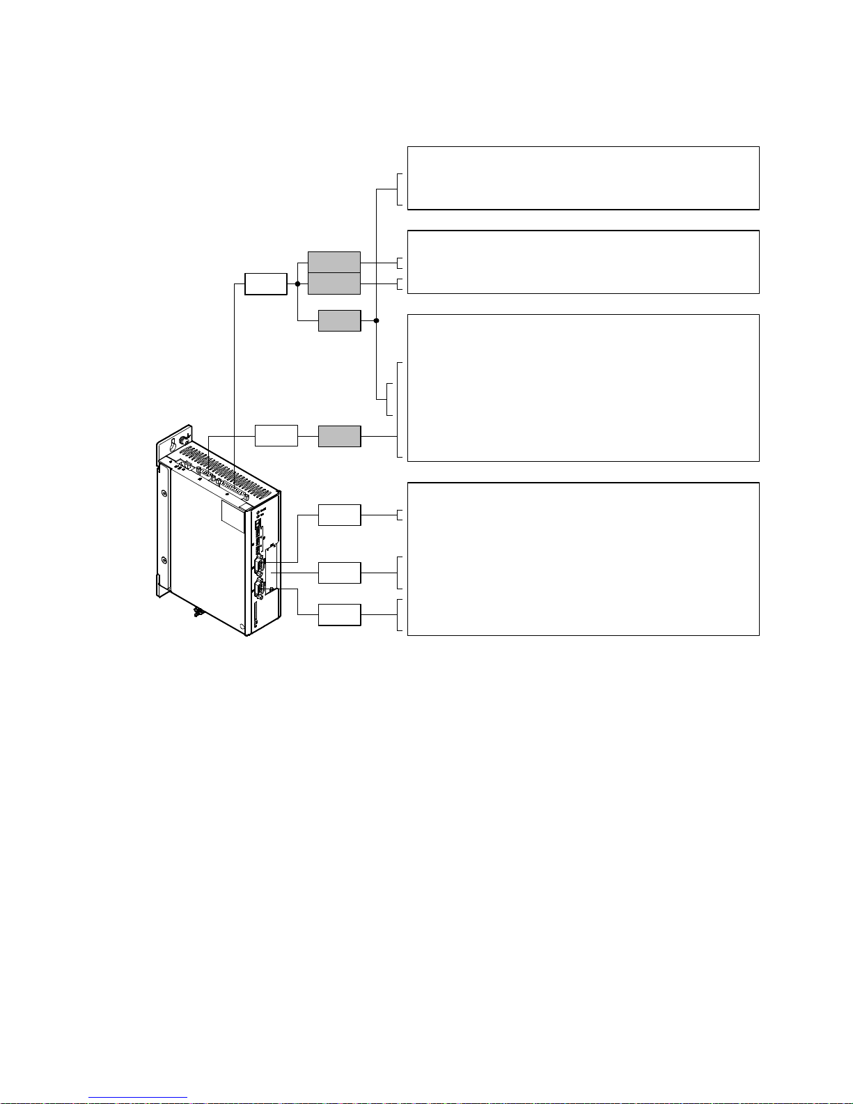
3 Control interfaces
3.1.2 Motor controller CMMS-ST-C8-7-G2
Digital interfaces:
– Digital inputs DIN0…13
– Digital outputs DOUT0…3
Analogue interfaces:
– Analogue inputs AIN0/#AIN0
– Analogue output AMON0
Synchronisation interfaces:
X1
±10V
0…10 V
24 V
1)
Encoder input:
– Incremental signals A/#A/B/#B/N/#N
– Pulse/direction signals CLK/#CLK/DIR/#DIR
– Forward/reverse signals CW/#CW/CCW/#CCW
X10
5V
2)
Encoder output:
– Incremental signals A/#A/B/#B/N/#N
Fieldbus interfaces:
X5
EXT
–RS485
– DeviceNet
–PROFIBUSDP
3)
3)
–CANopen
X4
1) HTL signal (high transistor logic): High signal = 24 V
2) TTL signal (transistor-transistor logic): High signal = 5 V
3) Interface module CAMC-... (optional)
–DriveBus
Fig. 3.2 Overview: Digital, analogue, synchronisation and fieldbus interfaces
Festo – GDCP-CMM S/D-FW-EN – 1404NH – English 47
Page 48
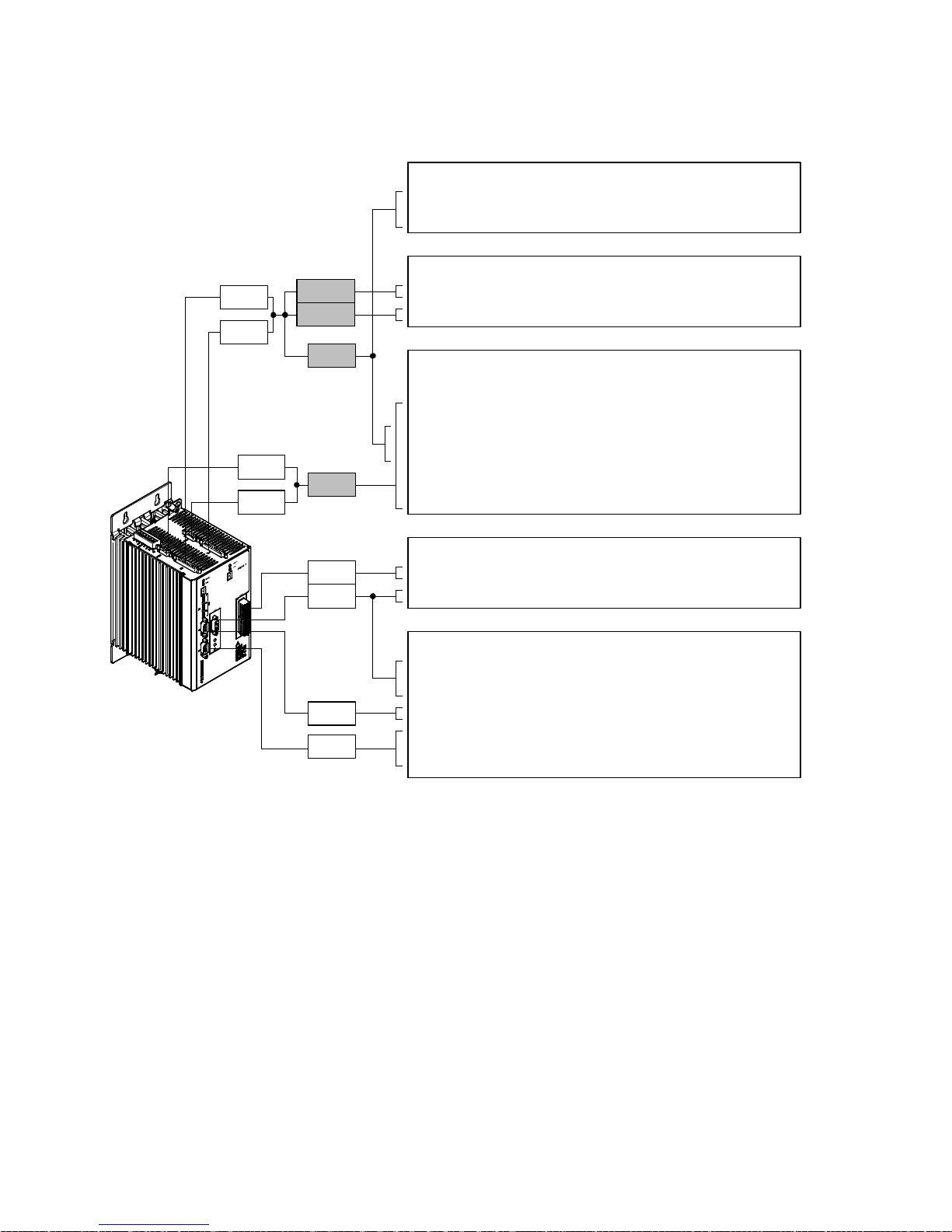
3 Control interfaces
3.1.3 Motor controller CMMD-AS-C8-3A
X1.1
±10V
0…10 V
X1.2
1)
24 V
X10.1
5V
2)
X10.2
Digital interfaces:
– Digital inputs DIN0…13
– Digital outputs DOUT0…3
Analogue interfaces:
– Analogue inputs AIN0/#AIN0
– Analogue output AMON0
Synchronisation interfaces:
Encoder input:
– Incremental signals A/#A/B/#B/N/#N
– Pulse/direction signals CLK/#CLK/DIR/#DIR
– Forward/reverse signals CW/#CW/CCW/#CCW
Encoder output:
– Incremental signals A/#A/B/#B/N/#N
Digital interfaces:
EXT2
EXT1
– Digital outputs EXT2-DOUT0…7
– Digital outputs EXT1-DOUT0…7
Fieldbus interfaces:
4)
4)
X5
X4
1) HTL signal (high transistor logic): High signal = 24 V
2) TTL signal (transistor-transistor logic): High signal = 5 V
3) I nput/output module CAMC-D-8E8A (optional)
4) Interface module CAMC-... (optional)
– DeviceNet
–PROFIBUSDP
–RS485
–CANopen
–DriveBus
Fig. 3.3 Overview: Digital, analogue, synchronisation and fieldbus interfaces
3)
3)
48 Festo – GDCP-CMMS/D-FW-EN – 1404N H – English
Page 49
3 Control interfaces
3.2 Digital interfaces [X1] [X1.1/X1.2/EXT1/EXT2]
3.2.1 Digital I/O modules (DIN…/DOUT…)
Motor controller CMMS:
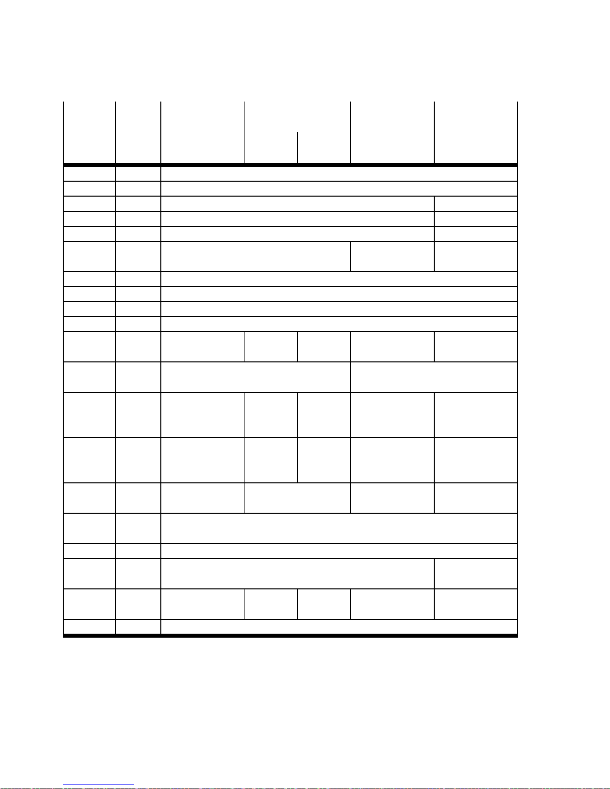
The motor controller has 14 digital inputs (DIN0…DIN13) and 4 digital outputs (DOUT0…3) at connection [X1]. The digital input/output signals are dependent on the operating mode selected page 50.
Motor controller CMMD:
The motor controller has 14 digital inputs (DIN0…DIN13) and 4 digital outputs (DOUT0…3) at each of
the connections [X1.1/X1.2]. The digital input/output signals are dependent on the operating mode
selected page 50.
The motor controller can be optionally expanded by an input/output module CAMC-D-8E8A at
slots EXT1/EXT2. The digital outputs ( EXT1-DOUT0…7) and (EXT2-DOUT0…7) can be freely configured
and assigned to one of the two strings. The 8 digital inputs cannot be used by the motor controller for
operation.
3.2.2 Selecting the operating mode/mode via digital input signals
The following operating modes/modes can be selected via the digital input signals “Mode bit 0” and
“Mode bit 1”.
Operating mode
Mode Mode bit 1
1)
(DIN9)
Mode bit 0
(DIN12)
2)
Individual record/homing mode Mode 0 0 0
Jog/teach-in mode Mode 1 0 1
Record linking operation Mode 2 1 0
Synchronisation mode Mode 3 1 1
1) The digital input (DIN9) is used as a sample input with flying measurement.
2) The digital input (DIN12) is used as an analogue input “AIN0” in speed, force or torque mode.
Tab. 3.1 Overview: Selecting the operating mode/mode via digital input signals “Mode bit 0/1”
Festo – GDCP-CMM S/D-FW-EN – 1404NH – English 49
Page 50
3 Control interfaces
3.2.3 Digital input/output signals as a function of the operating mode/mode
Designation
Pin
[X1.x]
[X1.1.x]
Mode 0
Individual record
Mode 1 Mode 2
Record linking
Jogging Teac hi ng
Mode 3
Synchronisation
[X1.2.x]
24 V DC [18] Supply voltage 24 V DC (output)
1)
GND 24 V [6] Load “DIN/DOUT”
DIN 0 [19] Record selection bit 0 –
DIN 1 [7] Record selection bit 1 –
DIN 2 [20] Record selection bit 2 CLK/CW_24
DIN 3 [8] Record selection bit 3 Halt record
DIR/CCW_24
sequence
DIN 4 [21] Output stage enable
DIN 5 [9] Controller enable
DIN 6 [22] Limit switch 0
DIN 7 [10] Limit switch 1
DIN 8 [23] Start positioning – Teach Start record
sequence
2)
DIN 9
[11] Mode bit 1 = 0 Mode bit 1 = 1
Start
synchronisation
(Sample)
DIN 10 [3] Record selection
bit 4
Jog+ Record
selection
NEXT1 –
bit 4
DIN 11 [16] Record selection
bit 5
Jog– Record
selection
NEXT2 –
bit 5
DIN 12
3)
[2] Mode bit 0 = 0 Mode bit 0 = 1 Mode bit 0 = 0 Mode bit 0 = 1
(AIN0)
DIN 13
3)
[15] Stop
(#AIN0)
DOUT0 [24] Controller ready for operation
DOUT1 [12] Motion complete (MC)
4)
Standstill
reached
DOUT2 [25] Start confirmed4)– Teach
confirmed
DOUT3 [13] Common error
4)
Start confirmed4)Position
synchronous
1) Internally connected with power supply “24 V DC” (input) at the connection [X9.6].
2) The digital input (DIN9) is used as a sample input with flying measurement.
3) The digital inputs (DIN12/DIN13) are used as analogue inputs (AIN0/#AIN0) in speed, force or torque mode.
4) The digital output can be freely configured (default setting in the Festo Configuration Tool (FCT)).
Tab. 3.2 Overview: Digital I/O modules dependent on the operating mode/mode
50 Festo – GDCP-CMMS/D-FW-EN – 1404NH – English
Page 51
3 Control interfaces
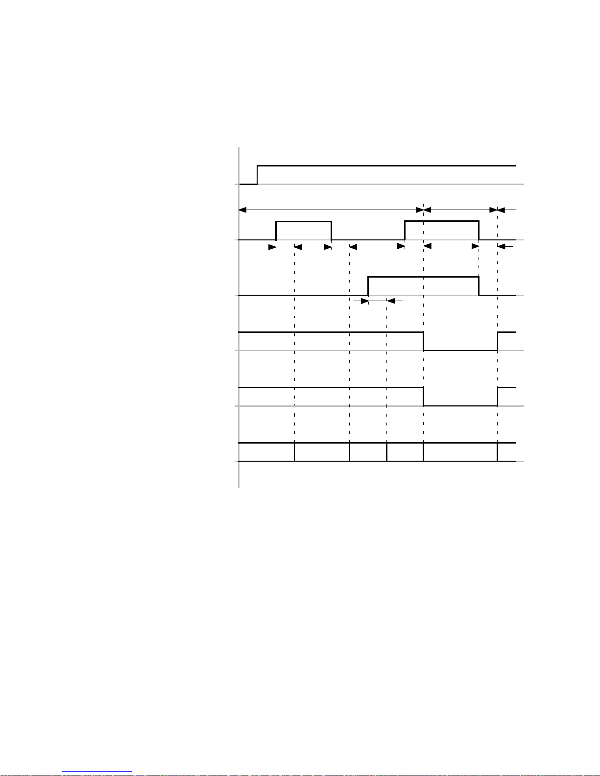
Timing diagram: Selecting the operating mode/mode via digital input signals
The timing diagram shows the dependency of the four operating mo des “Individual record (Mode 0)/
Jogging and teaching (Mode 1)/Rec ord linking (Mode 2)/Synchronisation (Mode 3)” on the digital input
signals “Mode bit 0/Mode bit 1”.
Controller ready for operation
(DOUT0)[X1.24]
Mode 0…2 Mode 3
Mode bit 0
(DIN12)[X1.2]
t1
t1
t1t1
Mode bit 1
(DIN9)[X1.11]
Motion Complete
Standstill reached
1)
2)
t1
(DOUT1)[X1.12]
Start confirmed
Position synchronous
1)
2)
(DOUT2)[X1.25]
Individual record, mode 0
Jog/teach, mode 1
Record linking, mode 2
0012
30
Synchronisation, mode 3
1) Only active for mode 0…2
2) Only active for mode 3
t1 ≤ 5ms
Fig. 3.4 Timing diagram: S electing the operating mode/mode via digital input signals “Mode bit 0/1”
Festo – GDCP-CMM S/D-FW-EN – 1404NH – English 51
Page 52
3 Control interfaces
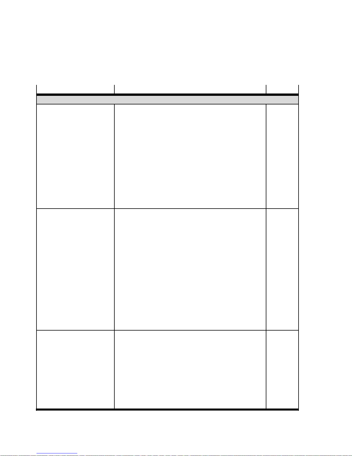
3.2.4 Digital input signals
The digital input signals are permanently assigned to t he digital inputs (DIN0…13). The function is dependent on the selected operating mode/mode of the control interface “digital inputs/outputs”
page 50.
Signal Description Signal
General operating signals
Enable Power
(DIN4)
[X1.21]/[X1.1.21/X1.2.21]
– High signal for release of the output stage (motor
energised) page 101.
– Low signal for immediate blocking of the output stage
high
active
• The category 0 STOP function, EN 60204-1 can be
realised in combination with an external safety
switching device desc ript ion “Safet y
function STO”,
– GDCP-CMMS-AS-G2-S1-...
– GDCP-CMMS-ST-G2-S1-...
– GDCP-CMMD-AS-S1-....
• Functional timing diagram of the input
page 107.
Enable Control
(DIN5)
[X1.9]/[X1.1.9/X1.2.9]
– High signal for release of the controller page 101.
– Low signal for blocking the controller enable function;
results in controlled braking of the motor
high
active
• The category 1 STOP function, EN 60204-1 can be
realised in combination with an external safety
switching device desc ript ion “Safet y
function STO”,
– GDCP-CMMS-AS-G2-S1-...
– GDCP-CMMS-ST-G2-S1-...
– GDCP-CMMD-AS-S1-....
• Functional timing diagram of the input
page 108.
– Low signal for acknowledgement of error messages
page 214.
Stop
(DIN13)
[X1.15]/[X1.1.15/X1.2.15]
Low signal for controlled stopping of the current
movement
• The category 2 STOP function, EN 60204-1 can be
low active
realised in combination with an external safety
switching device for standstill monitoring.
• Functional timing diagram for
– Individual record operation page 123
– Record linking operation page 141
– Homing mode page 159
52 Festo – GDCP-CMMS/D-FW-EN – 1404NH – English
Page 53
3 Control interfaces
Signal SignalDescription
Limit switches
Limit Switch 0
(DIN6)
[X1.22]/[X1.1.22/X1.2.22]
Limit Switch 1
(DIN7)
[X1.10]/[X1.1.10/X1.2.10]
Signal when the reference/end position is reached.
– With the configured edge of the limit switch 0,
reaching of the reference/end position is signaled.
Signal when the reference/end position is reached.
– With the configured edge of the limit switch 1,
reaching of the reference/end position is signaled.
Operating mode selection
Mode Select Bit 0
(DIN12)
Signals for selection of the operating mode/mode
page 49.
[X1.2]/[X1.1.2/X1.2.2]
Mode Select Bit 1
(DIN9)
[X1.11]/[X1.1.11/X1.2.11]
Record selection
Record Select Bit 0…5
Bit 0…2: (DIN0/…/DIN2)
Bit 3…5: (DIN3/DI N10/DIN11)
[X1.x]/[X1.1.x/X1.2.x]
Signals for selecting (binary co de) the positioning record.
– Individual record operation: Bit 0…5 active
page 121
– Record linking operation: Bit 0…2 active page 138
– Homing mode: Bit 0…5 active page 156
– Teach mode: Bit 0…5 active page 179
Individual record operation (mode 0)
Start Positioning
(DIN8)
[X1.23]/[X1.1.23/X1.2.23]
Signal for starting the individual record page 122.
– With the rising edge, the record selection is evaluated
and the paramet ers of the active positioning record
are executed by the controller-internal positioning
controller.
Record linking operation (mode 2)
Start Record Sequence
(DIN8)
[X1.23]/[X1.1.23/X1.2.23]
Signal for starting the record sequence page 139.
– With the rising edge, the record selection is evaluated
and the parameters of the active record sequence are
executed by the controller-internal positioning
controller/drive.
Halt Record Sequence
(DIN3)
[X1.8]/[X1.1.8/X1.2.8]
Signal for interrupting the record sequence page 140.
– With the low signal, the record sequence is stopped.
– With the high signal, the record sequence is
continued at the stopped position.
configurable
configurable
high
active
high
active
high
active
high
active
high
active
low active
Festo – GDCP-CMM S/D-FW-EN – 1404NH – English 53
Page 54
3 Control interfaces
Signal SignalDescription
Sequence control
NEXT1
(DIN10)
[X1.3]/[X1.1.3/X1.2.3]
Signals for control of the sequence controller.
Through the configured input (NEXT1/2), continuation
can be controlled to the next positioning record. With the
configured edge (rising/falling) the record sequence is
continued.
– Positioning record parameter (FCT) “Command:
NEXT2
(DIN11)
[X1.16]/[X1.1.16/X1.2.16]
NRI/NFI”:
Continuation is executed immediately with the edge.
– Positioning record parameter (FCT) “Command:
NRS/NFS”:
Continuation is executed with the edge and the
output signal “Motion complete = high”.
Homing mode (mode 0, positioning record 0)
Start Positioning
(DIN8)
[X1.23]/[X1.1.23/X1.2.23]
Starting for starting homing page 157.
– With the rising edge, homing is performed in
accordance with the parametrised homing method.
Jog operation (mode 1)
Jogging+
(DIN10)
[X1.3]/[X1.1.3/X1.2.3]
Signal for control of the positive jog travel page 174.
– With the rising edge, jog travel (creep/jog speed) is
started.
– With the falling edge, jog travel is ended.
Jogging–
(DIN11)
[X1.16]/[X1.1.16/X1.2.16]
Signal for control of the negative jog travel page 174.
– With the rising edge, jog travel (creep/jog speed) is
started.
– With the falling edge, jog travel is ended.
Teach operation (mode 1)
Teach
(DIN8)
[X1.23]/[X1.1.23/X1.2.23]
Signal for storing the teach/actual position page 180.
– With the rising edge, teaching is prepared. The cur-
rent actual position of the drive and the record selection (bit 0…5) are evaluated.
– With the falling edge, the current actual position is
temporarily stored in the selected positioning record.
The taught positions are not permanently stored until
there is a falling edge of the controller enable signal
(DIN5)[X1.9].
configurable
configurable
high
active
high
active
high
active
high
active
54 Festo – GDCP-CMMS/D-FW-EN – 1404NH – English
Page 55
3 Control interfaces
Signal SignalDescription
Synchronisation (mode 3)
Start Synchronisation
(DIN8)
[X1.23]/[X1.1.23/X1.2.23]
CLK/CW_24
(DIN2)
[X1.20]/[X1.1.20/X1.2.20]
DIR/CCW_24
(DIN3)
[X1.8]/[X1.1.8/X1.2.8]
Signal for starting synchronisation page 196.
– With the high signal, synchronisation is started.
– With the low signal, synchronisation is stopped.
Encoder signals for synchronising the motor controller.
– CLK: Pulse signal
– CW: Forward signal
Encoder signals for synchronising the motor controller.
–DIR:Directionsignal
– CCW: Reverse signal
Flying measurement
Sampling
(DIN9)
[X1.11]/[X1.1.11/X1.2.11]
Signal for storing the actual position page 200.
– With the configured edge of the sample signal, the
current actual position of the drive is taken over into
the sample memory. The higher-order controller can
interrogate the last stored actual position via the active fieldbus.
high
active
configurable
configurable
configurable edge
trigger
Tab. 3.3 Overview: Digital input signals
Festo – GDCP-CMM S/D-FW-EN – 1404NH – English 55
Page 56
3 Control interfaces
3.2.5 Digital output signals
The configurable digital output signals can be freely assigned to the digital out puts
(DOUT1/2/3)[X1.12/25/13]. The digital outputs (EXT1-DOUT0…7) or (EXT2-DOUT0…7) can be optionally configured by the motor controller CMMD with mounted input/output module CAMC-D-8E8A.
Signal
Operating status
Output stage active
(configurable)
Controller ready for
operation
(DOUT0)
[X1.24]/[X1.1.24/X1.2.24]
Quality
Enable power granted
(configurable)
Start
Acknowledge start
(configurable)
Description Signal
The signal is high as long as the following conditions are
met:
high
active
– The output stage enable signal (DIN4) is high
– The controller enable (DIN5) is high
– No error message is present
– The intermediate circuit is loaded
– Master control is issued
The signal is high as long as all of the following
conditions are met:
high
active
– The output stage enable signal (DIN4) is high
– The controller enable (DIN5) is high
– The stop signal (DIN13) is high
Exception (DIN13):
When using the “Analogue input” control interface,
theanalogueinput#AIN0isactive
– No error message is present
– The intermediate circuit is loaded
– Master control is issued
The signal returns the status of the digital input signal
“Output stage enable ( DIN4)”. This signal does not
high
active
contain the status of the output stage (see digital output
signal “Output stage active”)
The signal becomes low with the start of a positioning
low active
record.
– During individual record operation the signal remains
low until the digital input signal “Start positioning” is
withdrawn again.
– During record linking operation the signal is
automatically withdrawn ( approx. 16 ms) after setting
the digital input signal “Start record sequence”.
56 Festo – GDCP-CMMS/D-FW-EN – 1404NH – English
Page 57
3 Control interfaces
Signal SignalDescription
Speed
Target velocity reached
(configurable)
The signal is high as long as the actual speed is within the
parametrised message window (message “Speed
reached”) of the parametrised speed (positioning mode)
page 61.
Declared velocity achieved
(configurable)
The signal is high as long as the actual speed is within the
parametrised message window and the parametrised
declared speed (message “Speed reached”) page 62.
Standstill reached
(configurable)
The signal is high as long as the actual position is within
the parametrised message window (message “Speed
reached”) of the standstill status (0 mm/s) page 63.
Item
Motion Complete “MC”
(configurable)
The signal becomes high if the actual position is within
the parametrised message window and the parametrised
damping time (message “Target reached”) has expired
page 59.
Target position reached
(configurable)
The signal is high as long as the actual position is within
the parametrised message window (message “Target
reached”) related to the current setpoint position of the
positioning curve controller-internal positioning
controller page 59.
Remaining distance
message
(configurable)
The signal is high as long as the actual position is within
the parametrised message window (message “Remaining
distance”) page 64.
Homing
Homing mode complete
(configurable)
CMMS-AS/CMMD-AS:
– Single-turn absolute encoder (servo
motor EMMS-AS -...-TS...):
The signal becomes high as soon as homing has been
completed without error.
– Multi-turn absolute encoder (servo
motor EMMS-AS -...-TM...):
The signal is high. If homing is aborted due to an er-
ror, the signal becomes low.
CMMS-ST
– The signal becomes high as soon as homing has been
completed without error.
high
active
high
active
high
active
high
active
high
active
high
active
high
active
Festo – GDCP-CMM S/D-FW-EN – 1404NH – English 57
Page 58
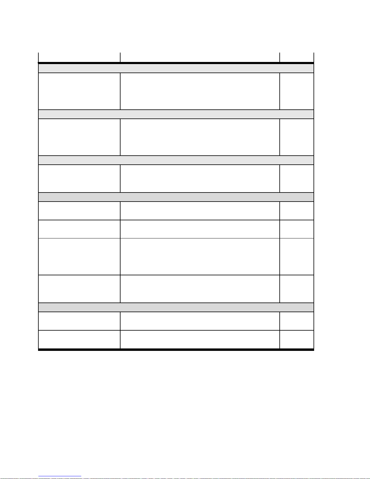
3 Control interfaces
Signal SignalDescription
Teaching
Teach Acknowledge
(DOUT2)
[X1.25]/[X1.1.25/X1.2.25]
The signal is low as long as the teach signal is high.
The signal becomes high after the parametrised
debounce time (for jog operatio n parameters) expires
page 180.
Synchronisation
Position synchronous
(DOUT2)
[X1.25]/[X1.1.25/X1.2.25]
The signal is high as long as the actual position is within
the parametrised message window (message “Following
error”) of the “Synchronisation” setpoint value
specification page 60.
Safety function
Safety halt active
(configurable)
The signal is h igh as long as the output stage enable
signal (DIN4)[X1.21] and the “Driver supply, impulse
block” (REL)[X3.2] = 0 V DC.
Error/warning
Error
(configurable)
Warning
(configurable)
Following error
(configurable)
The signal becomes low if at least one error message is
active.
The signal becomes high if at least one warning message
is active.
The signal becomes high as soon as the actual position is
outside the parametrised message window and the
parametrised response delay has expired (message:
Following error) page 60.
I2t Motor/output stage
(configurable)
The signal becomes high as soon as the motor or output
stage workload has exceeded the critical range
page 210.
Permanent signal
Off
The signal is permanently low (O V). low
(configurable)
On
The signal is permanently high (24 V). high
(configurable)
low active
high
active
high
active
low active
high
active
high
active
high
active
Tab. 3.4 Overview: Digital output signals
58 Festo – GDCP-CMMS/D-FW-EN – 1404NH – English
Page 59
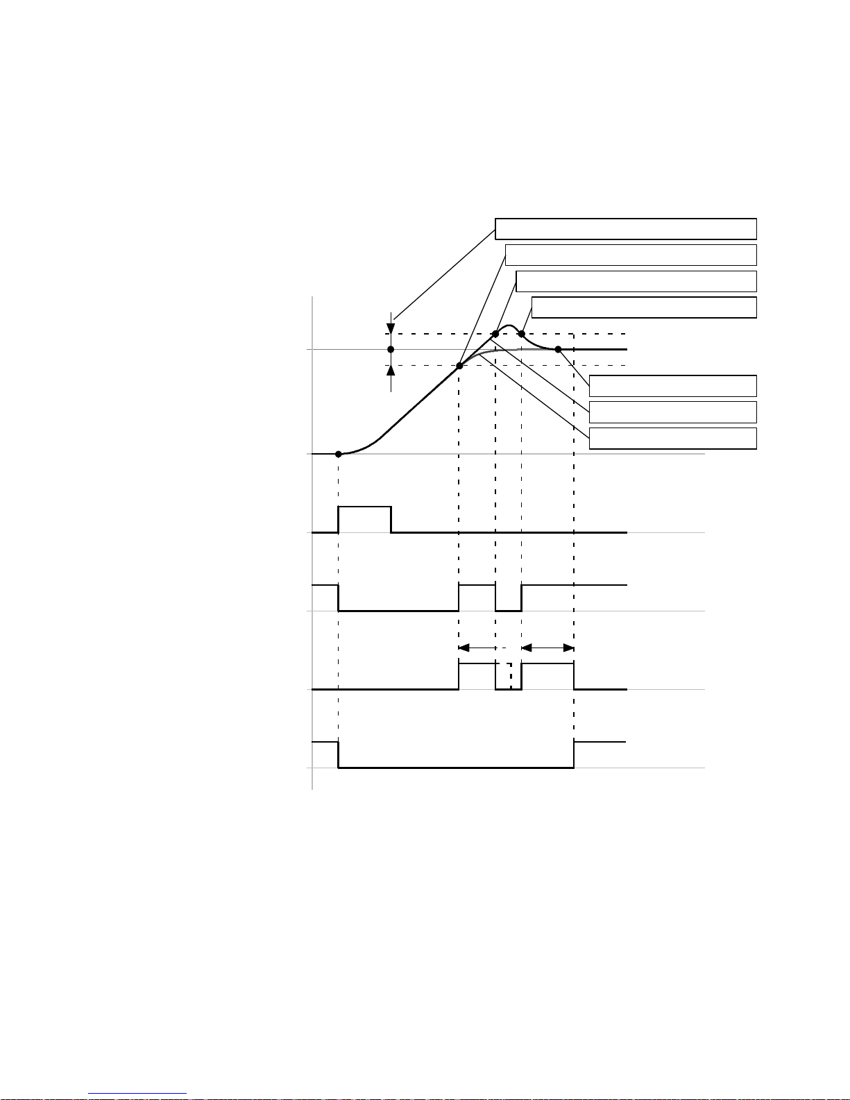
3 Control interfaces
3.2.6 Message “Target reached”
The course of the digital output signals “Target position reached” and “Motion Complete (MC)” is determined via the message “Target reached”.
Timing diagram: Message “Target reached”
Message window “Target reached”
“Damping time” start
“Damping time” termination
Parameter “position”
Start
(DIN8)[X1.23]
Setpoint position reached
(DOUT1/2/3)[X1.12/25/13]
Damping time
Δs
+
–
“Damping time” start
Target position
Actual position
Setpoint position
t1
t1
Motion complete
(DOUT1/2/3)[X1.12/25/13]
Δs = +/– … mm (linear axis)
= +/– … R (rotative axis)
(FCT: D ependent on the parameter “Message
window” in the message “Target reached”)
Fig. 3.5 Timing diagram: Message “Target reached”
Festo – GDCP-CMM S/D-FW-EN – 1404NH – English 59
t1 = … ms (FCT: Dependent on the parameter
“Damping time” in the message “Target
reached”)
Page 60
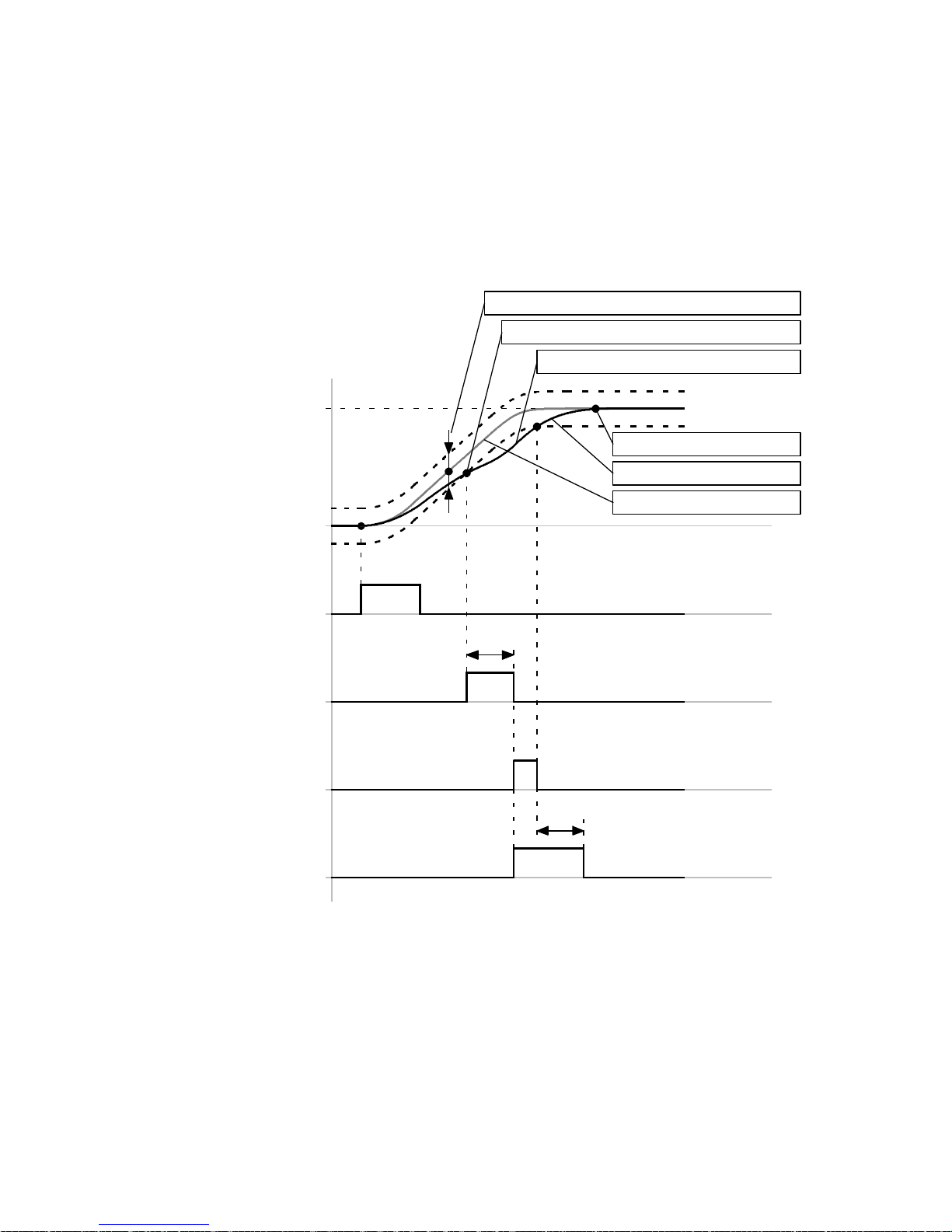
3 Control interfaces
3.2.7 Message “Following error”
The course of the digital output signals “Following error” and “Position synchronous” is determined via
the message “Following error”.
Timing diagram: Message “Following error”
Example: Message “Following error” with the reaction “Warn”. For additional information regarding the
reactions page 208.
Message window “Following error”
Start “Response delay”
Reaction “Warn”
Parameter “position”
Start
(DIN8)[X1.23]
Response delay
Following error
(DOUT1/2/3)[X1.12/25/13]
Following error
Message 170
Δs
+
Target position
Actual position
–
t1
t2
Setpoint position
Δs = +/– … mm (linear axis)
= +/– … R (rotative axis)
(FCT: D ependent on the parameter “Message
window” in the message “Following error”)
Fig. 3.6 Timing diagram: Message “Following error”
60 Festo – GDCP-CMMS/D-FW-EN – 1404NH – English
t1 = … ms (FCT: Dependent on the parameter
“Response delay” in the message “Following
error”)
t2 L 5 s (time after which the warning message
is automatically removed)
Page 61
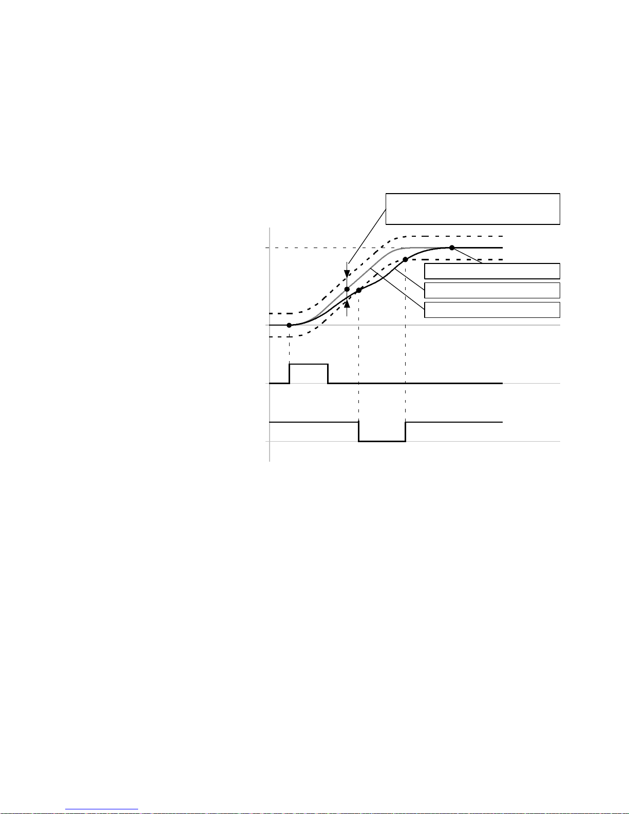
3 Control interfaces
3.2.8 Message “Speed reached”
The course of the digital output signals “Setpoint speed”, “Declared speed achieved” and “Standstill
reached” is determined via the message “Speed reached”.
Timing diagram: Digital output signal “Setpoint spe ed reached”
The timing diagram shows the dependency of the digital output signal “Setpoint speed” on the message window “Speed reached”.
Message window “Speed reached”
Parameter “speed”
+
Δv
Target speed
Actual speed
–
Target speed
Start
(DIN8)[X1.23]
Setpoint speed reached
(DOUT1/2/3)[X1.12/25/13]
Δv = +/– … mm/s (linear axis)
= +/– … rpm (rotative axis)
(FCT: D ependent on the parameter “Message window” in the message “Speed reached”)
Fig. 3.7 Timing diagram: Digital output signal “Setpoint speed reached”
Festo – GDCP-CMM S/D-FW-EN – 1404NH – English 61
Page 62
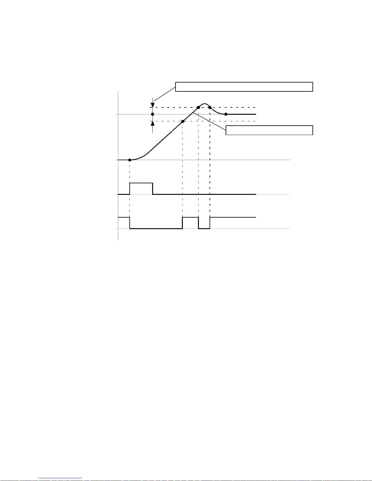
3 Control interfaces
Timing diagram: Digital output signal “Declared speed achieved”
The timing diagram shows the dependency of the digital output signal “Declared speed achieved” on
the message window “Speed reached”.
Message window “Speed reached”
+
Parameter “Declared
Δv
speed”
–
Actual speed
Start
(DIN8)[X1.23]
Declared speed reached
(DOUT1/2/3)[X1.12/25/13]
Δv = +/– … mm/s (linear axis) or
= +/– … rpm (rotative axis)
(FCT: D ependent on the parameter “Message window” in the message “Speed reached”)
Fig. 3.8 Timing diagram: Digital output signal “Declared speed achieved”
62 Festo – GDCP-CMMS/D-FW-EN – 1404NH – English
Page 63
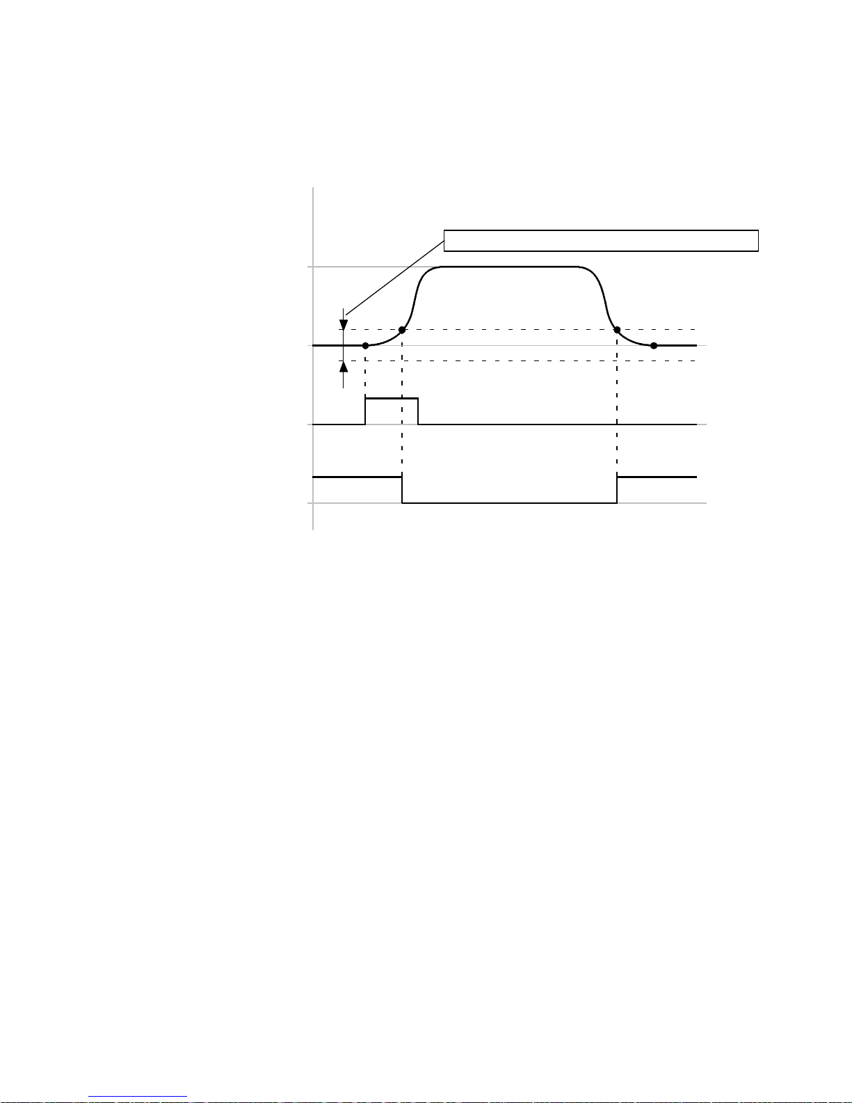
3 Control interfaces
Timing diagram: Digital output signal “Standstill reached”
The timing diagram shows the dependency of the digital output signal “Standstill reached” on the message window “Speed reached”.
Parameter
Message window “Speed reached”
“speed”
+
Standstill
Δv
–
Start
(DIN8)[X1.23]
Standstill reached
(DOUT1/2/3)[X1.12/25/13]
Δv = +/– … mm/s (linear axis) or
= +/– … rpm (rotative axis)
(FCT: D ependent on the parameter “Message window” in the message “Speed reached”)
Fig. 3.9 Timing diagram: Digital output signal “Standstill reached”
Festo – GDCP-CMM S/D-FW-EN – 1404NH – English 63
Page 64
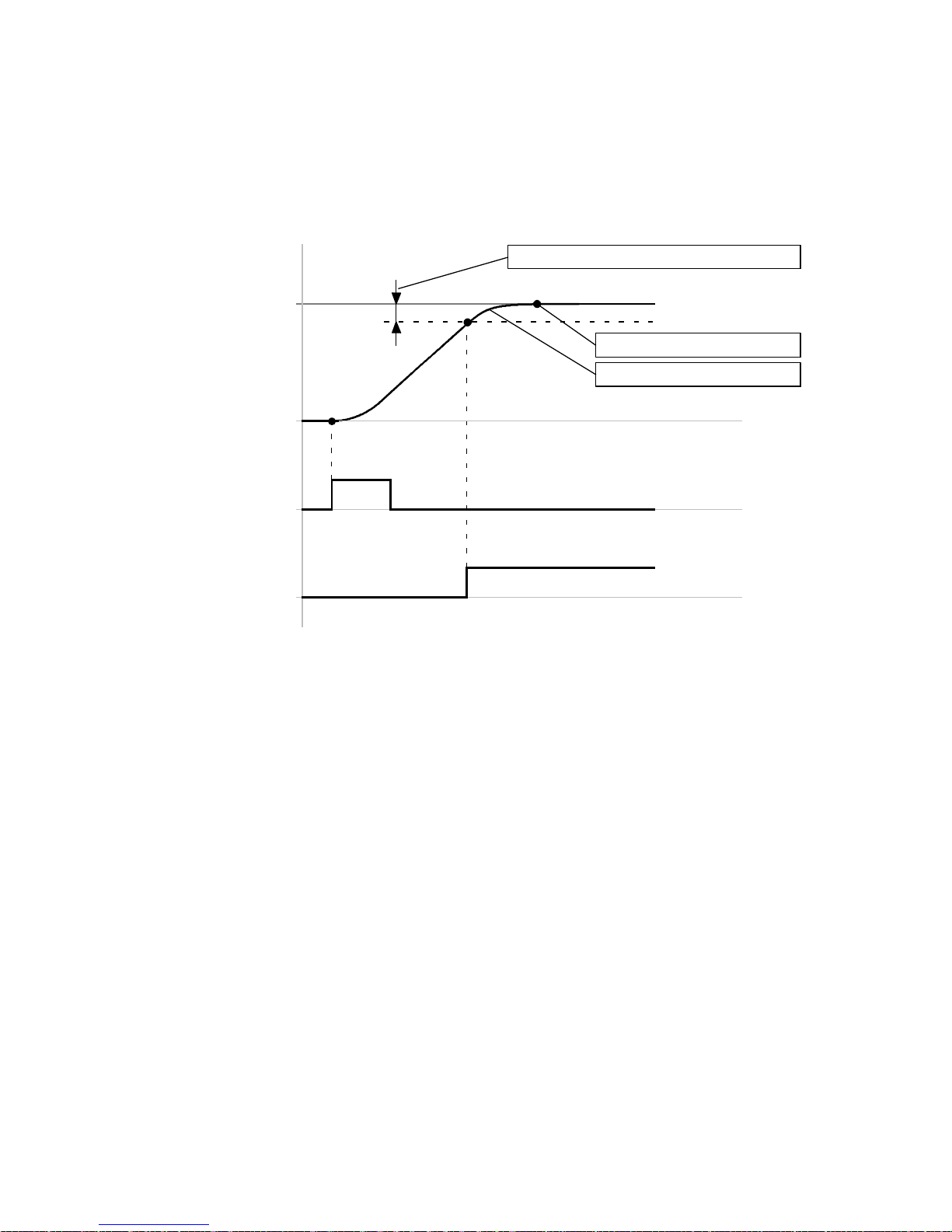
3 Control interfaces
3.2.9 Message “Remaining distance”
The course of the digital output signal “Remaining distance message” is determined via the message
“Remaining distance”.
Timing diagram: Message “Remaining distance”
Message window “Remaining dista nce”
Parameter “position”
Δs
Target position
Actual position
Start
(DIN8)[X1.23]
Remaining distance mes-
sage
(DOUT1/2/3)[X1.12/25/13]
Δs = +/– … mm (linear axis) or
= +/– … R (rotative axis)
(FCT: D ependent on the parameter “Message window” in the message “Remaining distance“)
Fig. 3.10 Timing diagram: Message “Remaining distance”
64 Festo – GDCP-CMMS/D-FW-EN – 1404NH – English
Page 65
3 Control interfaces
3.3 Analogue interface [X1] [X1.1/X1.2]
3.3.1 Analogue input/output (AIN0/AMON0)
Motor controller CMMS:
The motor controller has a differential analogue input (AIN0/#AIN0) and an analogue output (AMON0)
at connection [X1].
Motor controller CMMD:
The motor controller has a differential analogue input (AIN0/#AIN0) and an analogue output (AMON0)
at each of the connections [X1.1/X1.2].
Overview: Analogue input/output
Designation
AIn0
(DIN12)
1)
Description
Analogue input, differential
[X1.2]/[X1.1.2/X1.2.2]
#AIN0
(DIN13)
1)
[X1.15]/[X1.1.15/X1.2.15]
+VREF
Reference voltage, 10 V DC
[X1.4]/[X1.1.4/X1.2.4]
AGND
[X1.14]/[X1.1.14/X1.2.14]
Analogue load, reference potential for
– Reference voltage +VREF
– Analogue monitor
– Analogue input
SGND
“Analogue signal” screening
[X1.1]/[X1.1.1/X1.2.1]
AMONO
Analogue monitor (output)
[X1.17]/[X1.1.17/X1.2.17]
1) The analogue inputs (AI N0/#AI N0) are used in the positioning mode or during synchronisation (master operation) as digital inputs
(DIN12, mode bit 1) and (DIN13, stop signal).
Tab. 3.5 Overview: Analogue input/output
3.3.2 Analogue input signal (analogue setpoint value specification)
Function
Positive analogue signal
(AIN0)
[X1.2]/[X1.1.2/X1.1.2]
Negative analogue signal
(#AIN0)
[X1.15]/[X1.1.15/X1.2.15]
Tab. 3.6 Function overview: Analogue input signals (setpoint value signal)
Festo – GDCP-CMM S/D-FW-EN – 1404NH – English 65
Description
Differential analogue signals (± 10 V, 12 bit resolution) for controlling
the motor controller in the operating modes:
– Speed mode (speed setpoint value)
– Force/torque mode (torque setpoint value)
Page 66

3 Control interfaces
3.3.3 Analogue output signal (analogue monitor)
Function
Analogue monitor signal
(AMON0)
Description
Configurable monitor signal 0…10 V (Reference potential: Analogue
load “AGND”) page 203.
[X1.17]/[X1.1.17/X1.2.17]
Tab. 3.7 Function overview: Analogue output signal (analogue monitor)
66 Festo – GDCP-CMMS/D-FW-EN – 1404NH – English
Page 67
3 Control interfaces
3.4 Synchronisation interfaces [X1/X10] [X1.1/X1.2/X10.1/X10.2]
3.4.1 Encoder input for synchronisation (slave interface)
Motor controller CMMS:
The motor controller has different encoder inputs at the c onnections [X1/X10]. The encoder signals are
used for the “synchronisation” mode of the motor controller.
Motor controller CMMD:
The motor controller has different encoder inputs at the c onnections [X1.1/X1.2/X10.1/X10.2]. The
encoder signals are used for the “synchronisation” mode of the motor controller.
The following encoder signals are available:
Encoder input signals [5 V, TTL]
Encoder input [X10] [X10.1/X10.2]
CMMS CMMD
Incremental signals A/#A
Pulse/direction signals CLK/#CLK
Forward/reverse signals CW/#CW
1) Differential signals in accordance with RS422
2) The encoder input is used as an encoder output during encoder emulation (master operation).
1)
1)
B/#B
1)
N/#N
DIR/#DIR
1)
CCW/#CCW
[X10.1/6]
[X10.2/7]
[X10.3/8]
1)
1)
1)
[X10.1/6]
[X10.2/7]
2)
2)
2)
[X10.1.1/6]2)/[X10.2.1/6]
[X10.1.2/7]2)/[X10.2.2/7]
[X10.1.3/8]2)/[X10.2.3/8]
[X10.1.1/6]/[X10.2.1/6]
[X10.1.2/7]/[X10.2.2/7]
Tab. 3.8 Overview: Encode r input signals at the encoder input
The following encoder signals are optionally available at connection [X1] [X1.1/X1.2]:
Encoder input signals [24 V, HTL]
Digital input [X1] [X1.1/X1.2]
CMMS CMMD
Pulse/direction signals CLK
DIR
[X1.20]
[X1.8]
[X1.1.20]/[X1.2.20]
[X1.1.8]/[X1.2.8]
Forward/reverse signals CW
CCW
2)
2)
2)
Tab. 3.9 Overview: Encoder input signals at the digital input
Max. cycle rate
The encoder signals can be operated with the following cycle rates:
Digital input [X1]: Max. 20 kHz
Encoder input [X10]: Max. 150 kHz
Festo – GDCP-CMM S/D-FW-EN – 1404NH – English 67
Page 68

3 Control interfaces
3.4.2 Encoder output for encoder emulation (master interface)
Motor controller CMMS:
The motor controller has an encoder output at connection [X10]. Incremental signals
(A/#A/B/#B/N/#N) are generated by the encoder emulation ( operational function) and made available
via the encoder output.
Motor controller CMMD:
The motor controller has an encoder output at each of the connections [X10.1/X10.2]. Incremental
signals (A/#A/B/#B/N/#N) are generated by the encoder emulation ( operational function) and made
available via the encoder outputs.
Encoder output signals [5 V, TTL]
Encoder output [X10] [X10.1/X10.2]
CMMS CMMD
Incremental signals (A/#A)
(B/#B)
(N/#N)
1) Differential signals in accordance with RS422
2) The encoder output is used as an encoder input during synchronisation (slave operation).
1)
1)
1)
[X10.1/6]
[X10.2/7]
[X10.3/8]
2)
2)
2)
Tab. 3.10 Overview: Encoder output signals and control interface
[X10.1.1/6]2)/[X10.2.1/6]
[X10.1.2/7]2)/[X10.2.2/7]
[X10.1.3/8]2)/[X10.2.3/8]
2)
2)
2)
68 Festo – GDCP-CMMS/D-FW-EN – 1404NH – English
Page 69
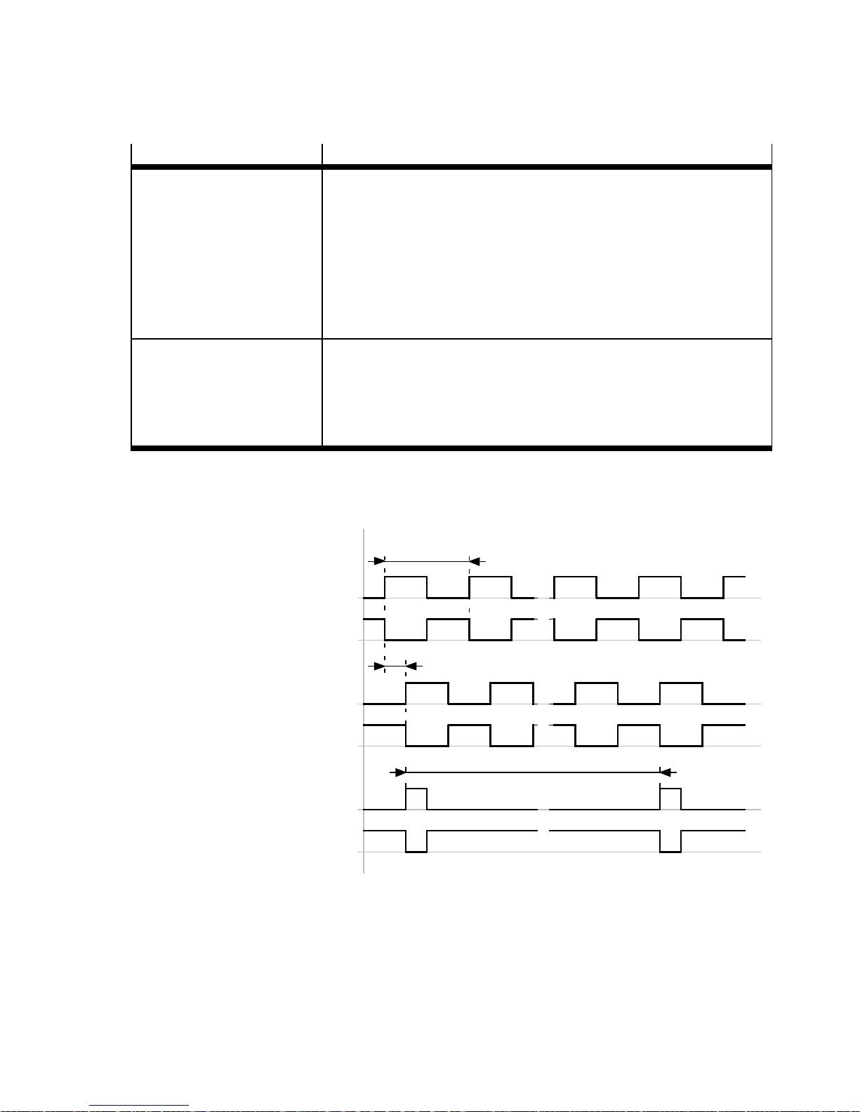
3 Control interfaces
3.4.3 Incremental signals (A/#A/B/#B/N/#N)
Signal
A/B (positive)
#A/#B (negative)
Description
Incremental signals for controlling the rotational speed/direction.
– The signals “A/#A” and “B/#B” are out of phase. In the basic set-
ting, without reversing the direction of rotation, the A signals are
90° ahead of the B signals if the direction of rotation is positive. If
the direction of rotation is negative, the B signals are 90° ahead of
the A signals. Through the phase shift and edge sequence (rising/
falling) of the signals “A/#A/B/#B”, the motor controller can de-
termine the rotational speed/direction.
N (positive)
#N (negative)
Zero pulse signals for identification of a revolution.
– The signals “N/#N” serve as a reference mark for a revolution. In
the “Synchronisation” operating mode, these signals are used for
counting the revolutions. With each zero-pulse passage, counting
of the signals “A/#A/B/#B” is restarted.
Tab. 3.11 Overview: Incremental signal (A/#A/B/#B/N/#N)
Timing diagram: Incremental signal for direction of rotation t o the right (basic setting)
Signal period
Incremental signal: A
Incremental signal: #A
90°
Incremental signal: B
Incremental signal: #B
One revolution
Zero pulse signal: N
Zero pulse signal: #N
Fig. 3.11 Timing diagram: Incremental signal for direction of rotation to the right (basic setting)
Festo – GDCP-CMM S/D-FW-EN – 1404NH – English 69
Page 70
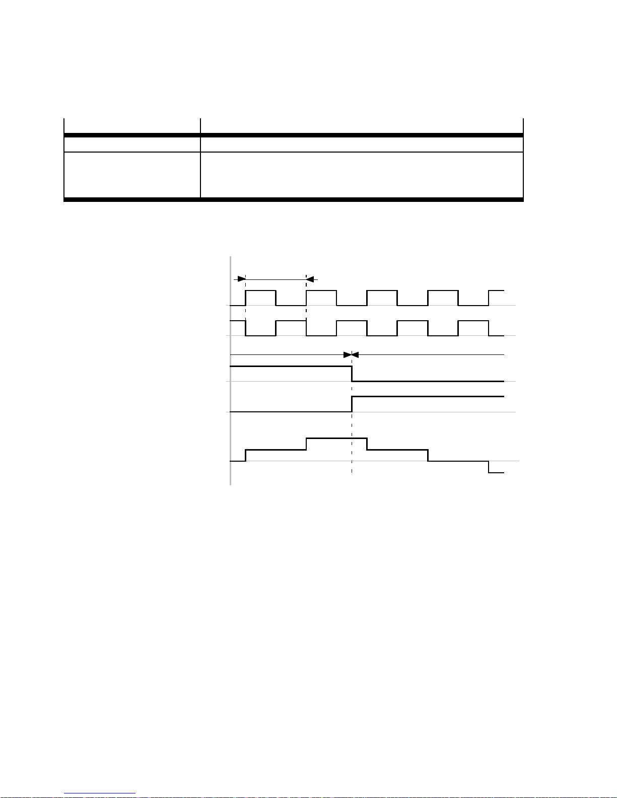
3 Control interfaces
3.4.4 Pulse/direction signals (CLK/#CLK/DIR/#DIR)
Through these signals, the motor controller can be controlled by a stepper motor control card.
Signal
Description
CLK/#CLK Pulse signals for control of the rotations/speed.
DIR/#DIR Direction signals for control of the direction of rotation.
– DIR = high: Positive direction of rotation
– DIR = low: Negative direction of rotation
Tab. 3.12 Pulse/direction signals (CLK/#CLK/DIR/#DIR)
Timing diagram: Pulse/direction signals
Pulse period
Pulse signal: CLK
Pulse signal:
#CLK
Direction of rotation “positive”
Direction of rotation “negative”
Direction signal: DIR
Direction signal: #DIR
Rotor position
Fig. 3.12 Timing diagram: Pulse/direction signals
70 Festo – GDCP-CMMS/D-FW-EN – 1404NH – English
Page 71
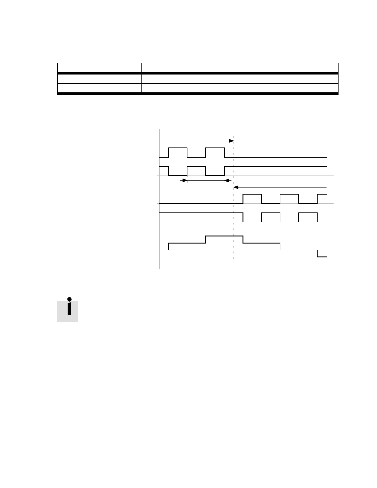
3 Control interfaces
3.4.5 Forward/reverse s ignals (CW/#CW/CCW/#CCW)
Signal
Description
CW/#CW Forward signals for control in a positive direction of rotation.
CCW/#CCW Reverse signals for control in a negative direction of rotation.
Tab. 3.13 Overview: Forward/reverse signals (CW/#CW/CCW/#CCW)
Timing diagram: Forward/reverse signals
Direction of rotation “positive”
Forward signal: CW
Forward signal: #CW
Pulse period
Direction of rotation “negative”
Reverse signal: CCW
Reverse signal: #CCW
Rotor position
Fig. 3.13 Timing diagram: Forward/reverse signals
Only one signal pair may be active for activation of the motor controller.
– Forward signals CW/#CW
– Reverse signals CCW/#CCW
Festo – GDCP-CMM S/D-FW-EN – 1404NH – English 71
Page 72
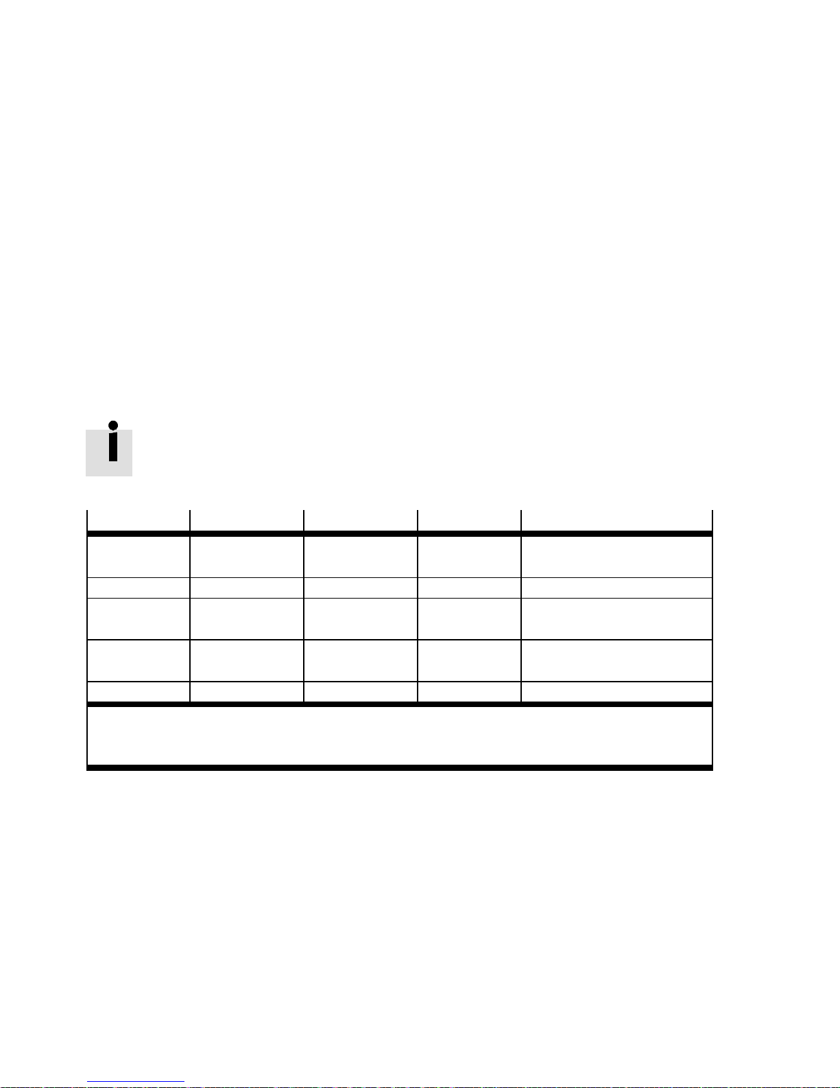
3 Control interfaces
3.5 Fieldbusinterfaces[X4][X5][EXT/EXT1]
3.5.1 Supported fieldbuses
The motor controller CMMS-AS/CMMS-ST/CMMD-AS can be controlled through various fieldbuses. As
standard, the fieldbuses “CANopen” or “DriveBus” can be controlled via the integrated CAN bus connection [X4] or the fieldbus “RS485” via the integrated RS232/RS485 connection [X5]. Optionally, the
fieldbuses “PROFIBUS DP” or “DeviceNet” can be controlled via the corresponding interface module at
the connection [E XT] (CMMS)/[EXT1] (CMMD).
Only one fieldbus may be used for activation of the motor controller.
The Festo Profile for Handling and Positioning (FHPP) and the CANopen device profile CiA 402 have
been implemented as the device profile (communication protocol) in the motor controller.
For every fieldbus, a factor group can be used so that application data can be transferred in user-specific units.
Overview: Fieldbus and device profile
The fieldbus documentation is included in the following media:
– CD-ROM of the motor controller CMMS-AS/CMMS-ST/CMMD-AS (scope of delivery)
– Support Portal www.festo.com/sp.
Fieldbus
Connection Interface module Device profile Documentation
CANopen [X4] — FHPP
CiA 402
DriveBus [X4] — CiA 402
PROFIBUS DP [Ext] (CMMS)
CAMC-PB FHPP
[Ext1] ( CMMD)
DeviceNet [Ext] (CMMS)
CAMC-DN FHPP
[Ext1] ( CMMD)
RS485 [X5] — CI
1) FHPP: Festo Handling and Positioning Profile page 74
2) CiA 402: Device profile CiA 402 page 74
3) CI : CAN Interpreter, device profile CiA 402
3)
Tab. 3.14 Overview: Fieldbus and device profile
1)
2)
2)
1)
1)
GDCP-CMMS/D-C-HP-…
GDCP-CMMS/D-C-CO-…
GDCP-CMMS/D-C-CO-…
GDCP-CMMS/D-C-HP-…
GDCP-CMMS/D-C-HP-…
page 240
72 Festo – GDCP-CMMS/D-FW-EN – 1404NH – English
Page 73
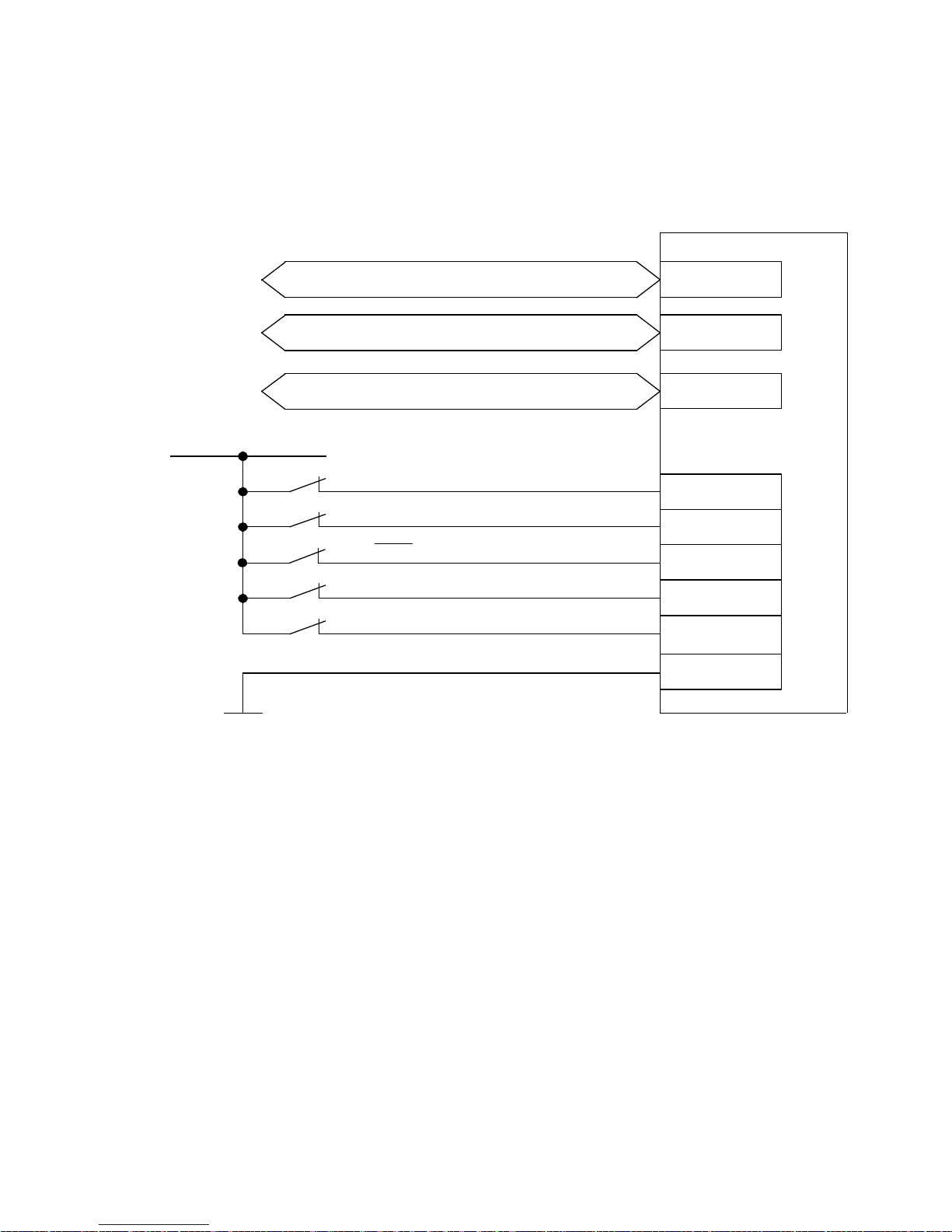
3 Control interfaces
3.5.2 Required digital inputs/outputs with a fieldbus activation
The connection diagram shows the required digital inputs for drive enable and movement via the fieldbus.
CMMS/CMMD
24 V DC
CANopen/DriveBus
RS485
PROFIBUS DP/DeviceNet
Output stage enable (D IN4)
Controller enable (DIN5)
Stop (DIN13)
Limitswitch0(DIN6)
Limitswitch1(DIN7)
Load “DIN/DOUT” / GN D 24 V
X4
X5
1)
EXT/EXT1
X1/X1.1/X1.2
21
9
15
2)3)
22
2)3)
10
6
1) Interface module CAMC-... (optional)
2) The limit switches are set by default to N/C contact (configuration over FCT)
3) Only required for applications with limited positioning range or homing methods with limit switch.
Fig. 3.14 Connection: Required digital inputs/outputs with fieldbus control
Festo – GDCP-CMM S/D-FW-EN – 1404NH – English 73
Page 74

3 Control interfaces
3.6 Device profiles for fieldbuses
3.6.1 Device profile: Festo handling and positioning profile (FHPP)
Independent of the fieldbus used, a uniform control concept can be implemented through the device
profile “FHPP”. The user does not have to know the specific functions of the respective fieldbuses or
controllers, but can commission and control the drive in the shortest possible time through a uniform
profile.
FHPP distinguishes between the triggering methods “record selection” and “direct operation”.
With record selection, the positioning records parametrised in the motor controller are used.
In the direct mode, the following operating modes can be used:
– Positioning mode (position control)
– Speed mode (speed adjustment)
– Force/torque mode (current control)
The operating modes c an be switched over in direct operation as needed.
For additional information “Device profile FHPP” description, GDCP-CMMS/D-C-HP-…
3.6.2 Device profile: CANopen, CiA 402 (for electric drives)
Through the device profile “CiA 402”, the following operating modes can be used:
– Positioning mode (CiA 402: Profile position mode)
– Homing mode (CiA 402: Homing mode)
– Interpolating position mode (CiA 402: Interpolated position mode)
– Speed mode (CiA 402: Profile velocity mode)
– Force/torque mode (CiA 402 : Profile torque mode)
Communication can take place either over SDOs ( service data objects) and/or PDOs ( process data
objects). Up to 2 PDOs are available for each sending direction ( transmit/receive).
For additional information “Device profile CiA 402” description, GDCP-CMMS/D-C-CO-…
74 Festo – GDCP-CMMS/D-FW-EN – 1404NH – English
Page 75
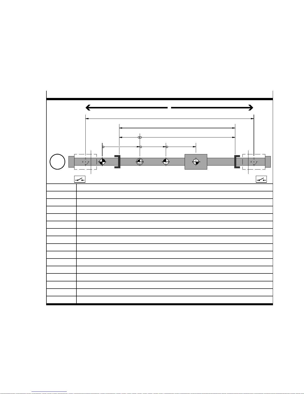
4 Dimension reference system
4 Measuring system
4.1 Measuring system for electrical drives
4.1.1 Measuring system for linear drives
Example: Homing method “limit switch”, negative direction
Run negative (–)
Run positive (+)
2
1
de
abc
M
REF AZ
SLN
PZ
TP/AP
LSN LSP
REF Homing point (reference point)
AZ Axis zero point
1)
1)
PZ Project zero point
SLN Negative software end position (SW limit negative)
SLP Positive software end position (SW limit positive)
LSN Limit switch (hardware) negative (Limit switch negative)
LSP Limit switch (hardware) positive (Limit switch positive)
SP Target position
AP Actual position1)
a Offset “axis zero point (AZ)”
b Offset “project zero point (PZ)”
c Offset “target/actual position (TP/AP)”
d Offset “Software end position negative (SLN)”
e Offset “Software end position positive (SLP)”
1 Effective stroke
2 Working stroke (no hardware limit switches)
SLP
1)
1)
1) Additional information page 161.
Tab. 4.1 Measuring system for linear drives
Additional information CD-ROM: Documentation “CMMS-AS_de.pdf/CMMS-ST_de.pdf/CMMDAS_de.pdf ” or the Festo Configuration Tool (FCT): Dynamic/static plug-in help.
Festo – GDCP-CMM S/D-FW-EN – 1404NH – English 75
Page 76
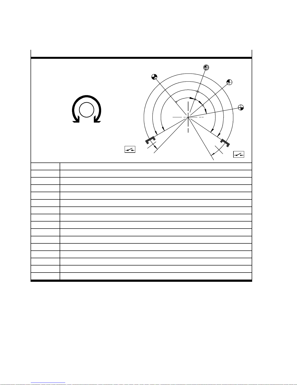
4 Dimension reference system
4.1.2 Measuring system for rotative drives
Example: Homing method “current position”
REF
2
1
AZ
PZ
Tur n ne ga t ive ( –)
M
Turn positive (+)
d
SLN
LSN
REF Homing point (reference point)
AZ Axis zero point
1)
1)
PZ Project zero point
SLN Negative software end position (SW limit negative)
SLP Positive software end position (SW limit positive)
LSN Limit switch (hardware) negative (Limit switch negative)
LSP Limit switch (hardware) positive (Limit switch positive)
SP Target position
AP Actual position
1)
a Offset “axis zero point (AZ)”
b Offset “project zero point (PZ)”
c Offset “target/actual position (TP/AP)”
d Optional: Offset “Software end position negative (SLN)”
e Optional: Offset “Software end position positive (SLP)”
1 Effective positioning range
2 Working positioning range (no hardware limit switches)
a
b
TP/AP
c
e
SLP
LSP
1)
1)
2)
2)
1) Additional information page 161.
2) In the “Endless positioning” operational function, no limit switch can be parameterised.
Tab. 4.2 Measuring system for rotative drives
Additional information CD-ROM: Documentation “CMMS-AS_de.pdf/CMMS-ST_de.pdf/
CMMD-AS_de.pdf ” or the Festo Configuration Tool (FCT): Dynamic/static plug-in help.
76 Festo – GDCP-CMMS/D-FW-EN – 1404NH – English
Page 77
4 Dimension reference system
4.2 Calculation rules for the measuring system
Point of reference Calculation rule
Axis zero point AZ =REF+ a
Project zero point PZ =AZ+ b =REF+ a+b
Negative software end position SLN =AZ+ d =REF+ a + d
Positive software end position SLP =AZ+ e =REF+ a + e
Target position/actual position TP/AP =PZ+ c =AZ+ b + c =REF+ a + b+c
Tab. 4.3 Calculation rules for the measuring system
4.3 Limit switch (hardware) and software end position
4.3.1 Limit switch LSN/LSP (hardware)
If the axis (linear/rotative) is restricted, the negative limit switch (LSN) and the positive limit switch
(LSP) is supported. These limit the absolute effective stroke/effective positioning range of the drive.
The switching function “NC contact” or “N/O contact” can be parameterised dependent on the limit
switch type.
One limit switch active:
If one of the limit switch positions is reached, the drive is braked with the reaction parametrised in the
FCT error management “PS off/Qstop/Warn” of message “430/431” page 208.
After that, the positioning direction of the respective active limit switch is blocked. That is, the drive can
only be run in the positioning direction of the inactive limit switch.
Both limit switches a ctive:
If both limit switches are active simultaneously, the drive is braked with the reaction parametrised in
the FCT error management “PS off/Qstop/Warn” of message “439” (the message “439” is configured
via message “430”) page 208.
4.3.2 Software end position SLN/SLP
If the axis is restricted, the negative software end position (SLN) and the positive software end position
(SLP) for limitation of the working stroke/working positioning range can also be parameterised relative
to the axis zero point between the limit switches (hardware). As with the LSN/LSP limit switches ( hardware), here, too, the positioning range is blocked when the software end position is blocked. In addition, before the software end position is reached, braking with the stop deceleration “limit switch” is
started so that the position of the software end position is not overtravelled.
Before starting, a check is made whether the target positions of the positioning records lie between the
software end positions SLN/SLP. If a target position lies outside this range, the positioning record is not
executed and the reaction parameterised in the FCT error management of messages “400…403” is
carried out.
Festo – GDCP-CMM S/D-FW-EN – 1404NH – English 77
Page 78

5 Commissioning
5 Commissioning
5.1 Configuration/parameterisation of the drive system and motor
controller
5.1.1 Festo Configuration Tool (FCT)
The Festo Configuration Tool (FCT) is the Windows-based software platform for configuration, parameterisation and commissioning of different components and devices from Festo.
– Management of data/files via the RS232 data interface (online) or memory card
• Device data: FCT parameterisation
• Firmware file: Firmware data
• Parameter file: DCO file on memory card
– Manual operation (e.g. jog, etc.)
–Diagnostics
– Recording of measurement data
– Automatic calculation of the controller data for the selected motor-gear unit-axis combination
– Manual precision adjustment of the controller data
The FCT c onsists of the following c omponents:
– a framework with uniform project and data management for all supported types of equipment
– one plug-in for every type of equipment (e. g. CMMS-AS/CMMS-ST/CMMD-AS)
The plug-ins are managed and starte d from the framework. They support the execution of all necessary
steps for configuration/parameterisation of the drive system and commissioning of the motor controller. Parameterisation of the motor controller is executed offline (without RS232 connection) on a PC.
This enables preparation for the actual commissioning, for example in the planning office when a system is being planned.
78 Festo – GDCP-CMMS/D-FW-EN – 1404NH – English
Page 79
5 Commissioning
5.1.2 Installing the FCT framework/plug-in
The FCT is installed on your PC with an installation programme:
1. Close all other programmes before starting installation.
2. Insert the “Festo Configuration Tool” CD in your CD-ROM drive.
• If Auto-Run is enabled: The installation process starts automatically.
• If Auto-Run is disabled: Manually launch the Setup.exe file on the CD-ROM.
Note
The operating system “Windows 2000/2003/XP/7/8” and Windows administrator
rights are required for installing the FCT framework.
3. Follow the instructions of the FCT wizard.
Note
The current FCT plug-in “CMMS-AS/CMMS-ST/CMMD-AS”, version 2.0.x, supports all
previous firmware versions ( up to 1.4.0.x.8).
For newer versions of t he motor controller, check whether there is an updated FCT plugin “CMMS-AS/CMMS-ST/CMMD-AS” available. If necessary, consult Festo.
5.1.3 Configuring/parameterising the Festo Configuration T ool (FCT)
1. Start the FCT:
– Double click on the FCT icon on the desktop
– Select the following Windows path:
[Start] [Open Program Path] [Festo Software] [Festo Configuration Tool].
2. Create a new project or open an existing project.
– [Menu bar] [Project] [New].
– Double click the existing project in the workspace.
Help for the FCT framewo rk: [Menu bar] [Help] [Contents FCT general].
3. Add a new component to the project as follows:
Menu bar [Component] [Add] [CMMS-AS/CMMS-ST/CMMD-AS].
Help for the FCT framewo rk: [Menu bar] [Help] [Contents FCT general].
4. Configure and parameterise the components of the drive system (motor controller, motor, gear unit,
axis, etc.) and the operating parameters (control interface, operating mode, error management,
etc.). Complete all further steps in accordance with the plug-in help instructions, chapter “Working
with the plug-in”:
– Menu bar [Help] [Contents of installed plug-ins] [Festo ( manufacturer name)]
[CMMS-AS/CMMS-ST/CMMD-AS (plug-in name or component name)].
– CD-ROM: Documentation “CMMS-AS_de.pdf/CMMS-ST_de.pdf/CMMD-AS_de.pdf ”.
– Dynamic/static help for the FCT plug-in page 80.
Festo – GDCP-CMM S/D-FW-EN – 1404NH – English 79
Page 80
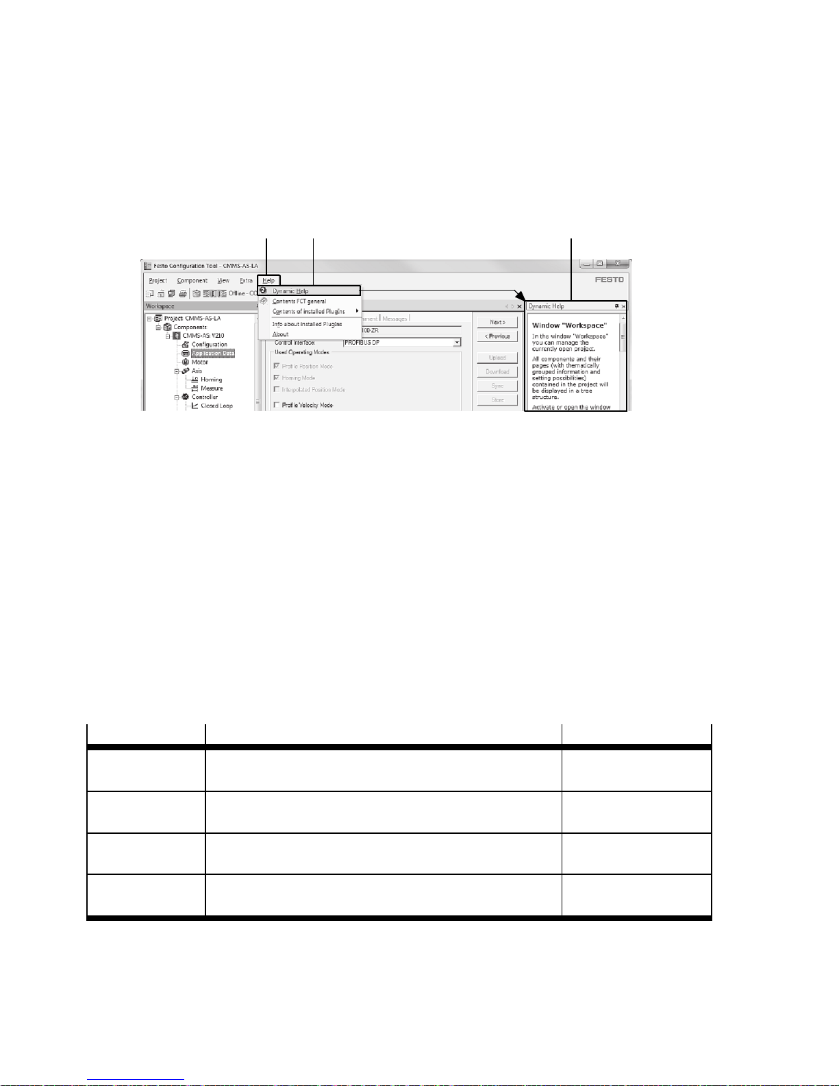
5 Commissioning
5.1.4 FCT Help
The following Help functions are available in the FCT:
Dynamic Help:
• Activate dynamic Help in the FCT user interface: [Menu bar] [Help] [Dynamic help]. When you click on
a field, Help is always displayed dynamically.
1 2 3
1 Menu bar: Help
3 Window: Dynamic Help
2 Button. Dynamic Help
Fig. 5.1 Overview: Dynamic Help in the Festo Configuration Tool (FCT)
Static Help:
– Click in the FCT user interface in a parameter/configuration field. When the F1 key is pressed, the
Static Help is displayed for the parameter/configuration field.
– Activate static Help in the FCT user interface:
[Menu bar] [Help] [Contents of installed plug-ins] [Festo] [CMMS-AS/CMMS-ST/CMMD-AS].
Clicking the button “CMMS-AS/CMMS-ST/CMMD -AS” displays the static Help.
Offline Help (PDF document):
– Print individual pages or all of the pages in a book directly from the Help contents by using the
“Print” button in the Help window.
– Print a prepared version of the help in Adobe PDF format:
Printed version
FCT help
Directory File
...(FCT installation directory)\Help\ – FCT_de.pdf
(framework)
Plug-in Help
CMMS-AS
Plug-in Help
CMMS-ST
Plug-in Help
CMMD-AS
...(FCT installation directory)\HardwareFamilies\
Festo\CMMS-AS \V...\Help\
…(FCT installation directory)\HardwareFamilies\
Festo\CMMS-ST\V…\Help\
…(FCT installation directory)\HardwareFamilies\
Festo\CMMD-AS\V…\Help\
– CMMS-AS_de.pdf
– CMMS-ST_de.pdf
– CMMD-AS_de.pdf
Tab. 5.1 Overview: Offline Help
80 Festo – GDCP-CMMS/D-FW-EN – 1404NH – English
Page 81
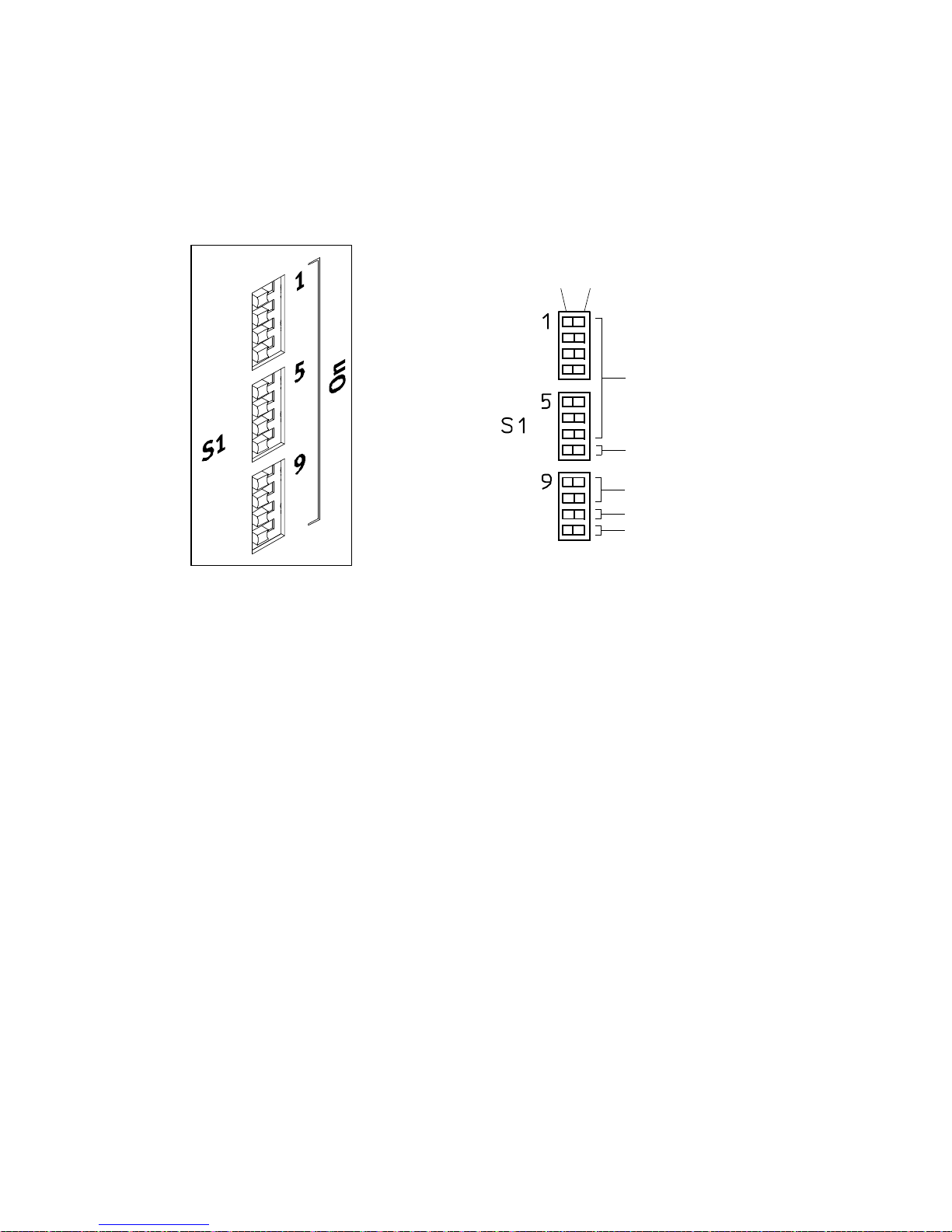
5 Commissioning
5.1.5 Configuring fieldbus/firmware functions via DIL switch
The following fieldbus/firmware functions can be configured via the DIL switches.
Overview: DIL switches [S1.1…12]
Switch position
Off
On
1 S1.1…7
2 S1.8
3 S1.9…10
4 S1.11
5 S1.12
1 Fieldbus address/MAC-ID co nfiguration
2 Firmware download activation from the
memory card
Fig. 5.2 Overview: DIL switches [S1.1…12]
3 Data rate configuration (CAN bus/DeviceNet)
4 CAN bus activation
5 Terminating resistor activation (CAN bus)
Festo – GDCP-CMM S/D-FW-EN – 1404NH – English 81
Page 82
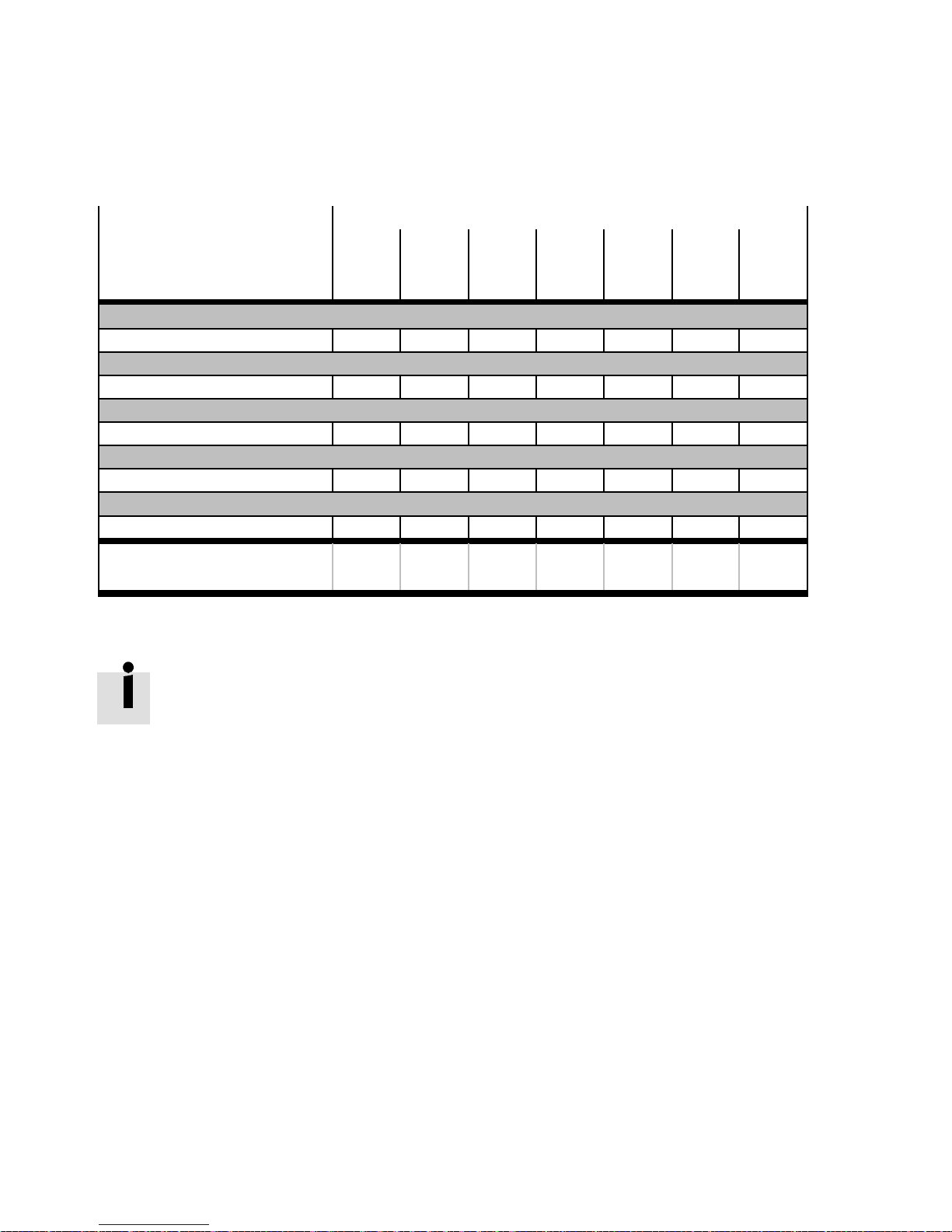
5 Commissioning
5.1.6 Fieldbus address/MAC-ID configuration
The address/ID configuration is evaluated for each power ON procedure or controller reboot (FCT). The
address/MAC-ID can be configured via the DIL switches [S1.1…7].
Fieldbus
DIL switch
[S1.7] [S1.6] [S1.5] [S1.4] [S1.3] [S1.2] [S1.1]
Bit 6 Bit 5 Bit 4 Bit 3 Bit 2 Bit 1 Bit 0
26=64 25=32 24=16 23=8 22=4 21=2 20=1
CANOpen
CAN address: 1…127 X X X X X X X
DriveBus
CAN address: 2…13 – – – X X X X
PROFIBUS DP
Bus address: 3…126
1)
X X X X X X X
DeviceNet
MAC-ID: 0…63 – X X X X X X
RS485
Address: 0…127 X X X X X X X
Example: 57 =
(Switch position)
1) The addresses “0…2” in Profibus DP are assigned to defined interfaces (e.g.: Higher-order controller, etc.).
+0
(OFF)
+32
(ON)
+16
(ON)
+8
(ON)
+0
(OFF)+0(OFF)+1(ON)
Tab. 5.2 Fieldbus address/MAC-ID configuration
Note the instructions for address/MAC-ID parameterisation of fieldbuses
Description “device profile FHPP”, GDCP-CMMS/D-C-HP-...
Description “device profile CiA 402”, GDCP-CMMS/D-C-CO-...
82 Festo – GDCP-CMMS/D-FW-EN – 1404NH – English
Page 83
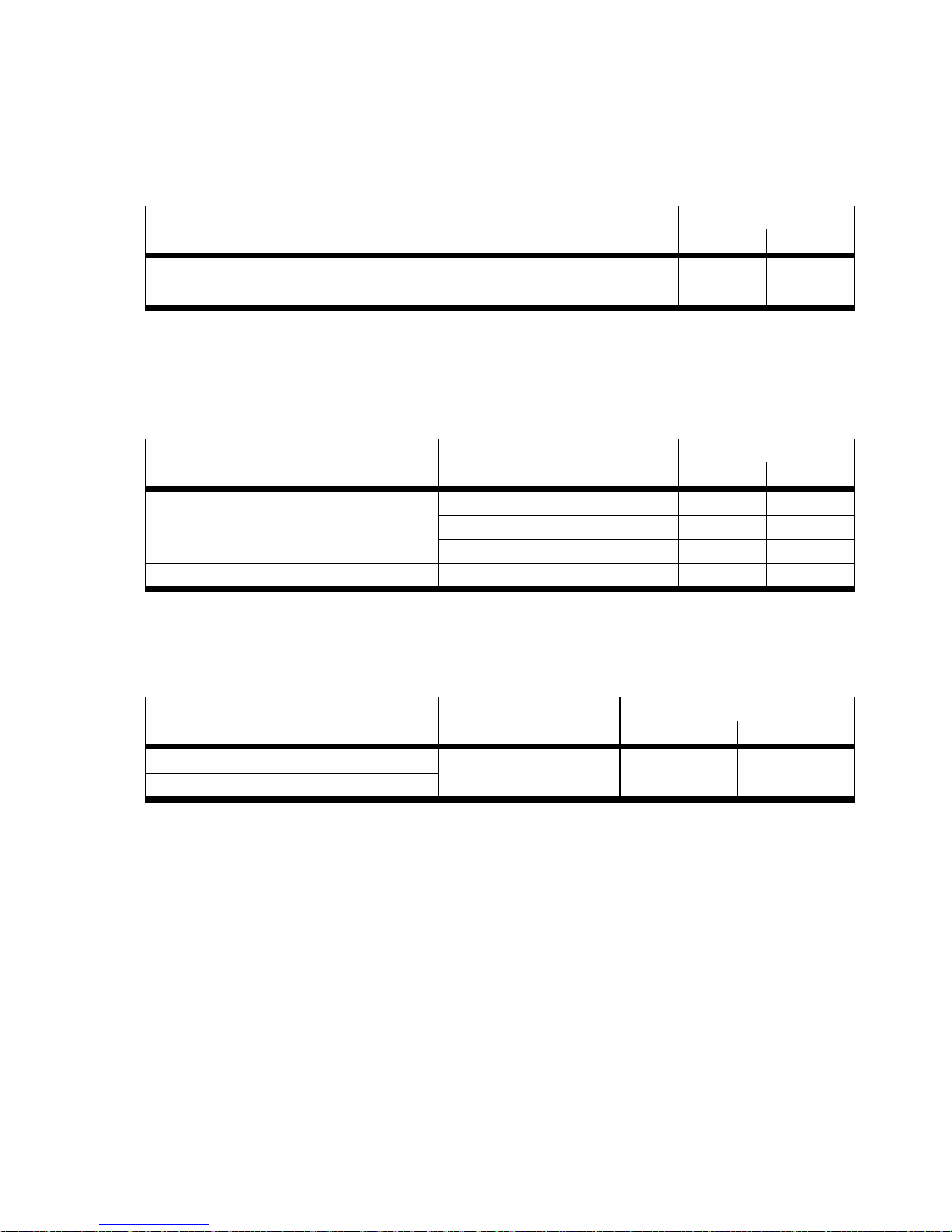
5 Commissioning
5.1.7 Firmware download activation from the memory card
The process for downloading firmware from the memory card c an be configured via DIL switch [S1.8]
page 87.
Bootloader
DIL switch [S1.8]
ON OFF
Download firmware file (.S) from the memory card after Power ON/FCT:
active inactive
Reboot controller
Tab. 5.3 Firmware download activation from the memory card
5.1.8 Data rate c onfiguration (CAN bus/DeviceNet)
The data rate configuration is evaluated for each power ON procedure or controller reboot (FCT). The
bit/transmission rate c an be configured via the DIL switches [S1.9/S1.10] .
Fieldbus
Bit/transmission rate DIL switch
[S1.10] [S 1.9]
CANopen (CAN bus)/DeviceNet 125 KBit/s ( 125 kBaud) OFF OFF
250 KBit/s ( 250 kBaud) OFF ON
500 KBit/s ( 500 kBaud) ON OFF
CANopen (CAN bus) 1 MBit/s (1000 kBaud) ON ON
Tab. 5.4 Data rate configuration ( CAN bus/DeviceNet)
5.1.9 CAN bus activation
Activation of the CAN bus can be configured via DI L switch [S1.11] .
Fieldbus
Port DIL switch [S1.11]
ON OFF
CANOpen CAN bus active
1)
inactive
DriveBus
1) The CAN bus interface is disabled with installation of the interface module “CAMC-PB/PROFI BUS DP” or “CAMC-DN/DeviceNet”.
Tab. 5.5 CAN bus activation
Festo – GDCP-CMM S/D-FW-EN – 1404NH – English 83
Page 84
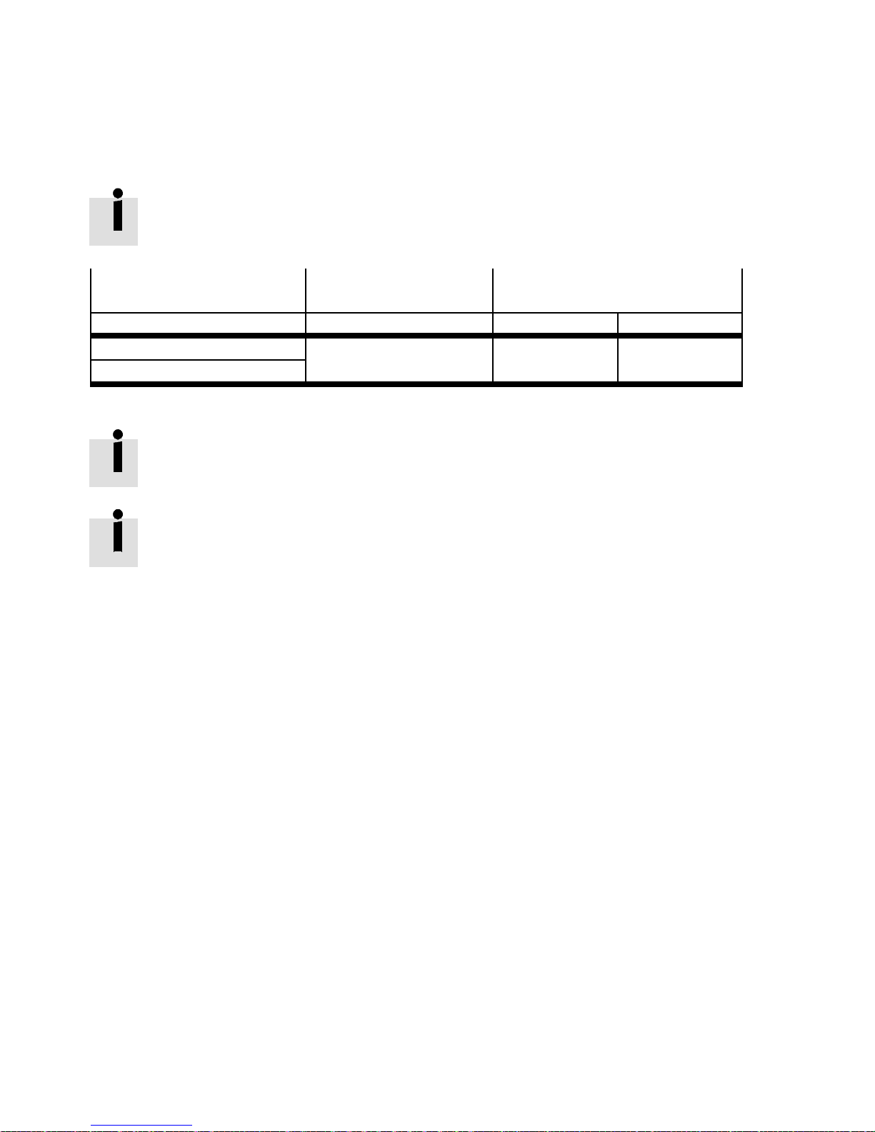
5 Commissioning
5.1.10 Terminating resistor activation (CAN bus)
The CAN bus is terminated at the ends via the terminating resistor. Final termination is to be ac tivated
at the end participants of the CAN bus.
DIL switch [S1.12] can be used exclusively for activation of the “CAN BUS” terminating
resistor.
Fieldbus
Note DIL switch
CANopen (CAN bus) Integrated terminating resDriveBus (CA N bus)
istor (120 Ω)
Tab. 5.6 Terminating resistor activation (CAN bus)
In the PROFIBUS DP, the terminating resistor is integrated into the “CAMC-PB” interface
module.
The terminating resistor (120 Ω ) can be connected externally to the end par ticipant, if
required, for DeviceNet and RS485.
S1.12
ON OFF
active inactive
84 Festo – GDCP-CMMS/D-FW-EN – 1404NH – English
Page 85
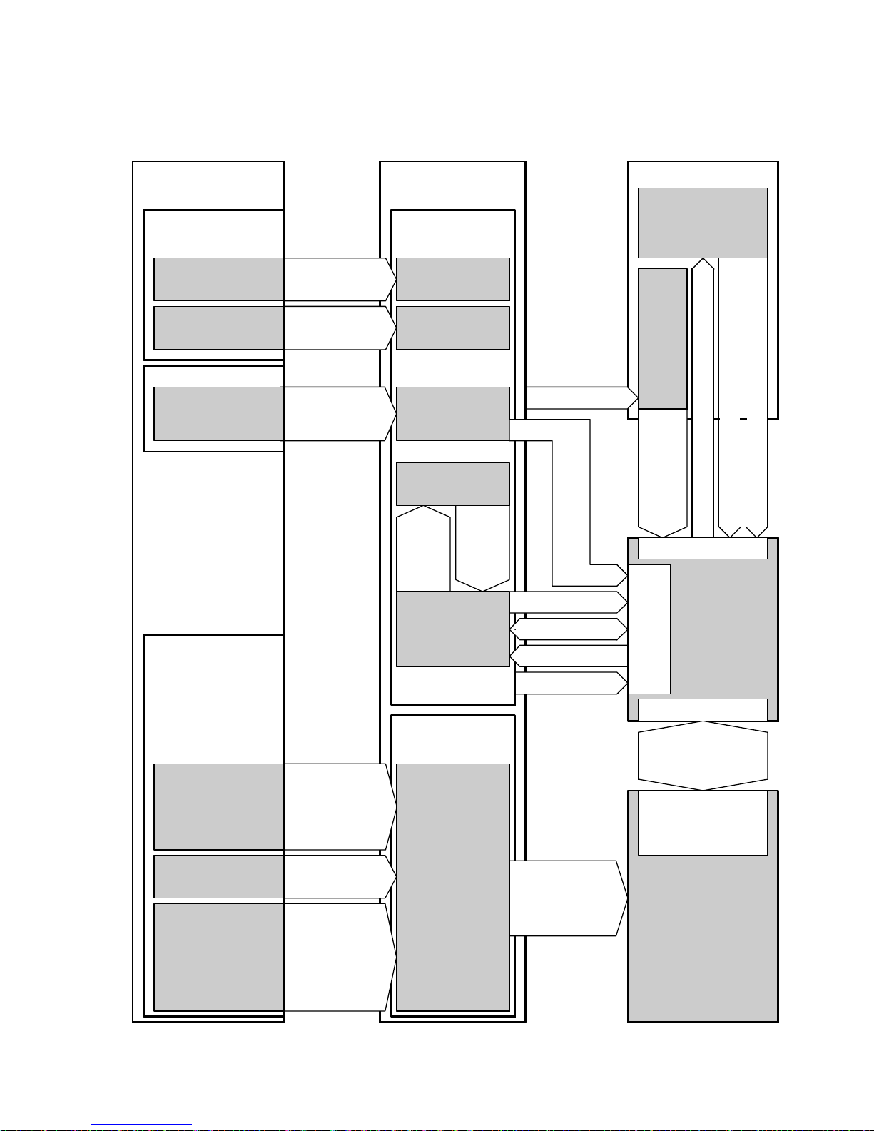
5 Commissioning
5.2 Data interfaces (parameter/firmware)
CD-ROM/
www.festo.com/sp
Festo Configuration
T ool (FCT)
Framework
Plug-in file
Firmware
Firmware file
Save/
execute
Save/
execute
Save/
Execute/
FCT: Import
PC Me mory card
Parameter file
FCT software
Installation
(.DCO)
Firm-
FCT: Controller >> SD
ware
Installation/
update
Firmware file
Copy
FCT:
Firmware download
file
(.S)
DIL switch S1.8:
Switch position = ON
Archive file
(.ZIP)
FCT:
Archive
FCT:
Extract
M1
FCT: SD >> Controller
FCT: Read from SD after restart
Device descriptions (EDS/GSD)
and function elements
EDS file:
–CANopen
– DeviceNet
–DriveBus
GSD file:
–PROFIBUSDP
Function element
file:
–CODESYS
–Step7
– RSLogix 5000
Save/
execute
Save/
execute
Save/
execute
Device data
Controller software
Controller
data management
FCT: Download
FCT: Synchronisation
FCT: Upload
FCT: Save
Download
Motor
X5
controller
X1/X4/EXT
Control/parameter
interface
Device profile:
–FHPP
–CiA402
Controller
Fig. 5.3 Overview: Data interfaces (parameter/firmware)
Festo – GDCP-CMM S/D-FW-EN – 1404NH – English 85
Page 86
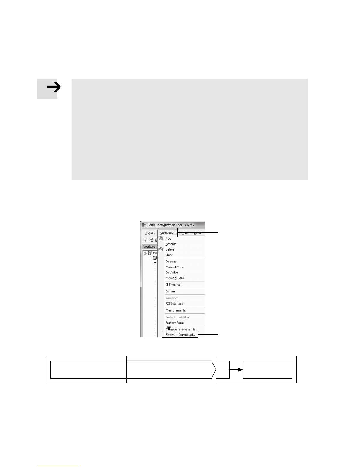
5 Commissioning
5.2.1 Firmware file
The firmware for the motor controller is included in the firmware file. The firmware file can be updated
online from a PC or via the memory card.
Note
Loss of the parameter set in the motor controller
In the event of a firmware download, the parameter set of the motor controller is deleted (“factory setting” status).
– Before downloading the firmware, back up the device data to the Festo Configura-
tion Tool (FCT) (Upload/Synchronisation) or save the current parameter set of the
motor controller to the memory c ard (FCT: Controller >> SD) as a parameter file
(.DCO).
– After downloading the firmware load the device data from the Festo Configuration
Tool (FCT) to the motor controller (Download) or load the parameter file (.DCO) from
the memory c ard to the motor controller (FCT: SD >> Controller).
5.2.2 Downloadingthefirmwarefile(FCT>>motorcontroller)
Theprocessfordownloadingthefirmwarefilecanbestartedviathefollowingbuttons.
FCT
Firmware file
Festo Configuration Tool (FCT)
RS232
2 Firmware download
1
2
CMMS/CMMD
X5
Permanent
memory
1 “Component” menu bar 2 Firmware Download
Fig. 5.4 Overview: Downloading the firmware file (FCT >> motor controller)
86 Festo – GDCP-CMMS/D-FW-EN – 1404NH – English
Page 87
5 Commissioning
5.2.3 Downloading the firmware file (.S) (memory card >> motor controller)
The process for downloading the firmware file (.S) from the memory card can be configured via DIL
switch [S1.8]. If the DIL switch position = ON, the process for downloading the firmware is restarted
with every Power ON procedure/controller reboot (FCT).
Memory card
Firmware file (.S)
DIL switch [S1.8]
Switch position = ON
CMMS/CMMD
M1
Permanent
memory
Fig. 5.5 Downloading the firmware file (.S ) (memory card >> motor controller)
To download the firmware from the memory card, proceed as follows:
1. Copy the firmware file (.S) from the PC to the memory card.
Note:
– Only one firmware file should be stored on the memory c ard.
– No subdirectories should be created o n the memory card.
File names
Example
Letters Format Extension
large/small 32.1 .S CMMS-AS: FW_CMMS-AS_V1p4p0p2p6.S
CMMS-ST: FW_CMMS-ST_V1p4p0p1p6.S
CMMD-AS: FW_CMMD-AS_V1p4p0p3p6.S
Tab. 5.7 Requirement for firmware file names
2. Insert the memory card into the card slot [M1].
3. Set the DIL switch [S 1.8] to the “ON” position.
4. Switch the “control section” power supply off and on.
5. During the boot procedure the motor controller performs a check (illuminated decimal point “.” on
the seven-segment display) to verify whether a memory card is inserted in the card slot [M1] and
whether the card contains a valid firmware version.
Possible causes of an error:
– Memory card is damaged
– Memory card is not inserted.
– Firmware file is damaged.
– The firmware version in the motor controller and on the memory card are identical.
If the errors listed above occur, the firmware is not downloaded and the firmware last
saved in the permanent memory is loaded.
6. The process for downloading the firmware file is executed ( flashing decimal point “.” on the sevensegment display) if a valid firmware file is present on the memory card and if this file is of a different
version to the firmware currently in use.
Festo – GDCP-CMM S/D-FW-EN – 1404NH – English 87
Page 88

5 Commissioning
If multiple firmware files are present on the memory card, the firmware file with the latest
date is loaded into the motor controller!
Whentheprocessfordownloadingthefirmwarestarts,thefirmwareinthepermanent
memory is initially deleted. If the download fa ils or if the power supply was interrupted
during the download process, no firmware will have been transferred to the permanent
memory. The firmware download process must be restarted again.
7. The newly loaded firmware star ts automatically.
8. Set the DIL switch [S 1.8] to the “OF F” position.
88 Festo – GDCP-CMMS/D-FW-EN – 1404NH – English
Page 89
5 Commissioning
5.2.4 Device data (FCT)
The device data contains all of the data that has been parameterised, configured and saved via the
Festo Configuration Tool (FCT).
5.2.5 Downloading/synchronising/uploading/saving device data
(FCT <</<=>/>> motor controller)
The device data can be transferred between the FCT and the motor controller as follows:
– Download (>>): From FCT to the motor controller
– Upload (<<): From the motor controller to the FCT
– Synchronisation (<=>): Between FCT and motor controller
Note
Loss of device data
If the “control section” power supply is interrupted, any modifications made to the
device data that have not been saved to the permanent memory will be lost.
– Save all modifications made to the device data in the permanent memory of the
motor controller (FCT: Save).
Festo – GDCP-CMM S/D-FW-EN – 1404NH – English 89
Page 90
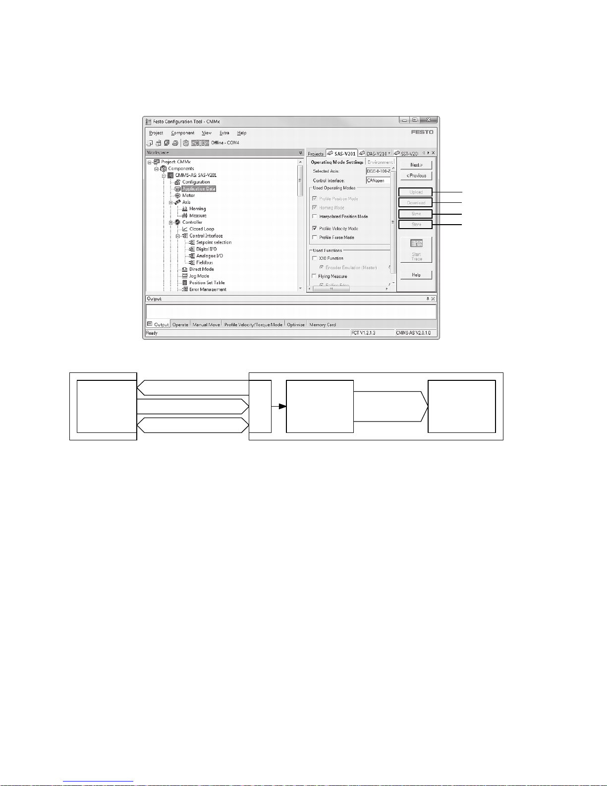
5 Commissioning
The process for transferring device data can be started via the following buttons.
Festo Configuration Tool (FCT)
1
2
3
4
FCT
Device
data
RS232
1 Upload
2 Download
CMMS/CMMD
Main
X5
memory
4 Save
3 Synchronisation
1 Upload
The current device data on the motor
controller is loaded into the Festo
Configuration Tool (FCT).
2 Download
The current device data on the Festo
Configuration Tool (FCT) is loaded into the
motor controller.
3 Syncronisation
The device data on the Festo Configuration
Tool (FCT) and the motor controller is
synchronised.
4 Store
The device data is saved from the main
memory to the permanent memory of the
motor controller.
Fig. 5.6 Overview: Downloading/synchronising/uploading/saving device data
(FCT <</=/>> motor controller)
Permanent
memory
90 Festo – GDCP-CMMS/D-FW-EN – 1404NH – English
Page 91
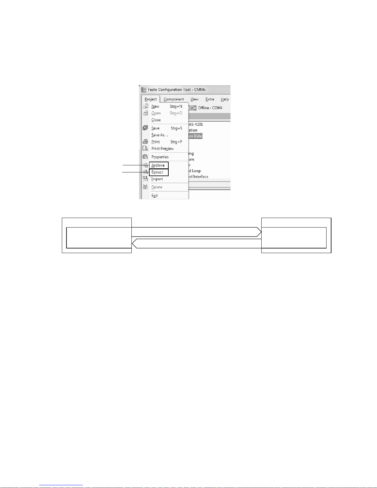
5 Commissioning
5.2.6 Archiving/extracting device data (FCT >>/<< PC)
The process for transferring device data can be controlled via the following buttons.
Festo Configuration Tool (FCT)
1
2
FCT
Device data
1 Archive
2 Extract
1 Archive:
The device data from the Festo Configuration
Tool (FCT) is saved to the PC's hard disk as an
archive file (.ZIP).
2 Extract:
The archive file (.ZIP) containing the device
data is loaded from the PC's hard disk into
the Festo Configuration Tool (FCT).
Fig. 5.7 Overview: Archiving/extracting device data (FCT >>/<< PC)
PC
Hard disk
Archive file (.ZIP)
Festo – GDCP-CMM S/D-FW-EN – 1404NH – English 91
Page 92
5 Commissioning
5.2.7 Parameter file (.DCO)
The parameter file (.DCO) contains the complete parameter set for the motor controller.
The parameter file (.DCO) can be transferred between the memory card and motor controller as follows:
– SD>>Controller/after restart ... (read): From the memory card to the motor controller
– Controller>>SD (write): From the motor controller to the memory card
Requirement for parameter file names
File names
Example
Letters Format File name Extension
large 8.3 8-digit
1)
.DCO CMMS-AS: CMMSAS01.DCO
CMMS-ST: CMMSST01.DCO
CMMD-AS: CMMDAS01.DCO
1) xxxxxxnn.DCO:
x = digits 1–6 are used for the file name. Any ASCI I characters can be used here.
n = digits 7+8 are used for the consecutive number of the file. This increases automatically from “00”.
Tab. 5.8 Requirement for parameter file names
92 Festo – GDCP-CMMS/D-FW-EN – 1404NH – English
Page 93
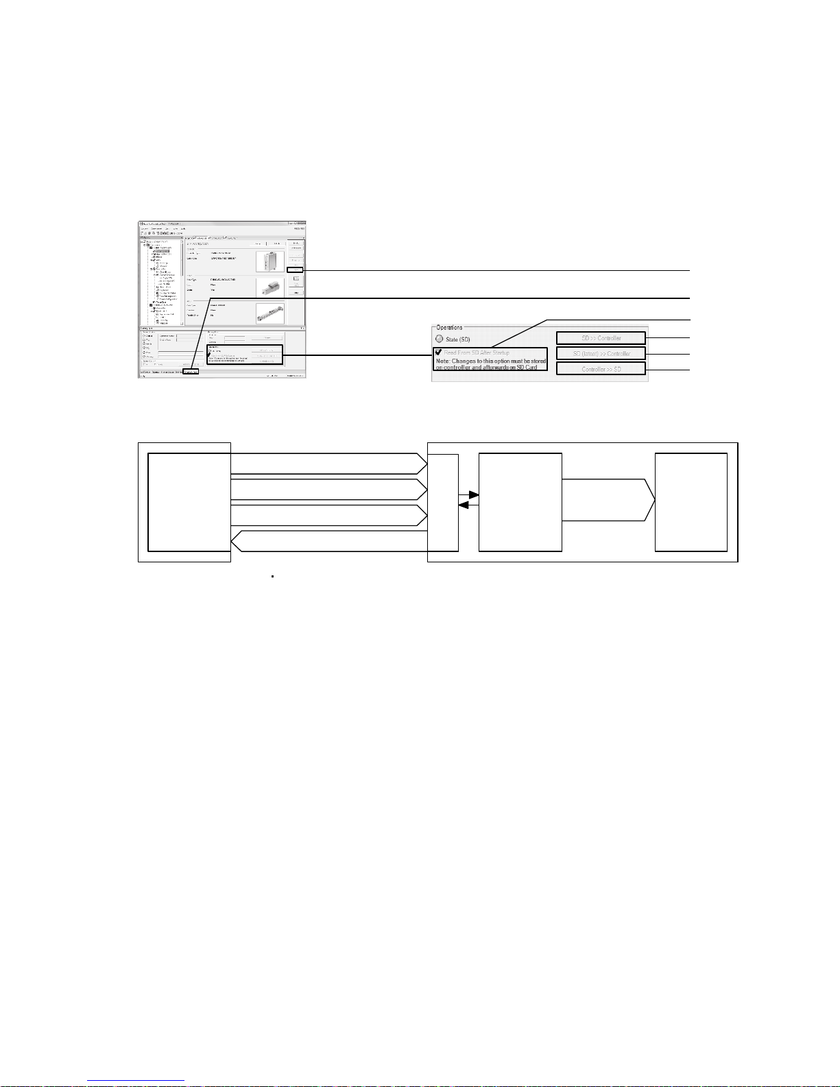
5 Commissioning
5.2.8 Reading/writing/saving the parameter file (.DCO)
(memory card >>/<< motor controller)
The process for transferring a parameter file (.DCO) can be started via the following buttons or check
boxes.
Festo Configuration Tool (FCT)
1
2
3
4
6
6
2 Memory
card
CMMS/CMMD
Parameter
file (.DCO)
3 After restart ...
4 SD>>Controller
X5
Main
memory
1 Save
Permanent
memory
5 SD( ...)>>Controller
6 Controller>>SD
1 Store
In the motor controller, the current
parameter set is written from the main
memory and saved to the permanent
memory.
2 Memory Card
3 Read from SD after Startup:
If the check box is active (check mark set), a
search is conducted on the memory card for
the parameter file (.DCO) designated
“Latest” after every restart (Power ON/FCT:
Restart controller); when located, it is loaded
automatically into the main memory of the
motor controller.
4 SD>>Controller (SD>>Controller):
A search is conducted on the memory card
for the parameter file (.DCO) designated
“Latest”; when located, it is loaded
automatically into the main memory of the
motor controller.
5 SD(latest)>>Controller:
A search is conducted on the memory card
for the parameter file ( .DCO) with the latest
date; when located, it is loaded
automatically into the main memory of the
motor controller.
6 Controller>>SD:
The latest parameter set of the motor
controller is written to the memory card as a
parameter file (.DCO).
Fig. 5.8 Overview: Downloading/uploading the parameter file (.DCO) (memory card >>/<< motor
controller)
Festo – GDCP-CMM S/D-FW-EN – 1404NH – English 93
Page 94
5 Commissioning
5.3 Commissioning the motor controller
5.3.1 Preparing for initial start-up
CAMC module and cover plate:
• Check the installation of the module or cover plate on slot [EXT] [EXT1/EXT2].
• Motor controller CMMD:
The interface module CAMC (PROFIBUS DP/DeciveNet) should only be installed in slot [EXT1].
Electrical interfaces:
• Check the wiring of the system (controller/motor/motor encoder/limit switch/mains supply/safety
switching device/etc.).
• Check the pin allocation of the connector [X...] and the connection of the screening.
• Check the connection of the protective conductor (PE).
• Check all electrical connections for short circuit and disconnection.
For additional information “Mounting and installation” description,
GDCP-CMMS-AS-G2-HW-…/GDCP-CMMD-AS-HW-…/GDCP-CMMS-ST-G2-HW-…
Fieldbus interfaces:
• Check the fieldbus address/MAC-I D page 82.
• Check the data rate (CAN bus/DeviceNet) page 83.
• Check CAN bus activation (CANopen/DriveBus) page 83.
• Check the terminating resistor:
– The activation of the CA N bus terminating resistor (CANopen/DriveBus) page 84.
– The activation of the PROFI BUS terminating resistor
“Device profile FHPP” description, GDCP-CMMS/D-C-HP-….
– The connection of the external terminating resistor (DeviceNet/RS485)
“Mounting and installation” description,
GDCP-CMMS-AS-G2-HW-…/GDCP-CMMD-AS-HW-…/GDCP-CMMS-ST-G2-HW-…
Firmware update:
• Check the status of the firmware version Support portal: www.festo.com/sp.
Note
Before using a newer firmware version, check whether a newer version of the FCT plugin or documentation is available Support portal: http://www.festo.com/sp.
94 Festo – GDCP-CMMS/D-FW-EN – 1404NH – English
Page 95
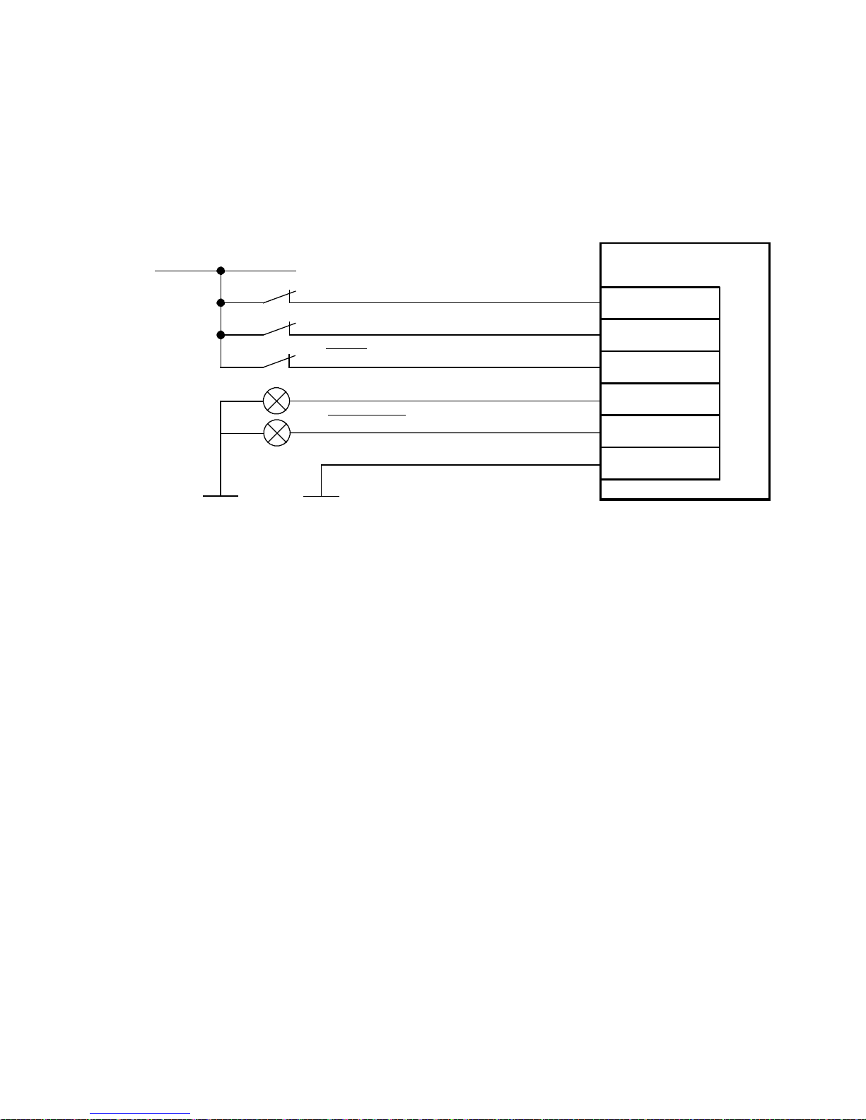
5 Commissioning
5.3.2 Required digital inputs/outputs for operation
In order to operate the motor controller safely in all operating modes, the following digital inputs/outputs are required.
Connection: Digital inputs/outputs for operation
24 V DC
Output stage enable ( DIN4)
Controller enable (DIN5)
Stop (DIN13)
1)
Controller ready for operation (DOUT 0)
Common error (DOUT3)
2)
Load “DIN/DOUT” (GND 24 V)
The connection diagram shows the switch positions in operation.
1) The digital input (DIN13) is used as an analogue input (#AIN0) in speed, force or torque mode.
2) Default setting, freely configurable in the Festo Configuration Tool (FCT).
Fig. 5.9 Connection: Digital inputs/outputs for operation
CMMS/CMMD
X1/X1.1/X1.2
21
9
15
24
13
6
Festo – GDCP-CMM S/D-FW-EN – 1404NH – English 95
Page 96
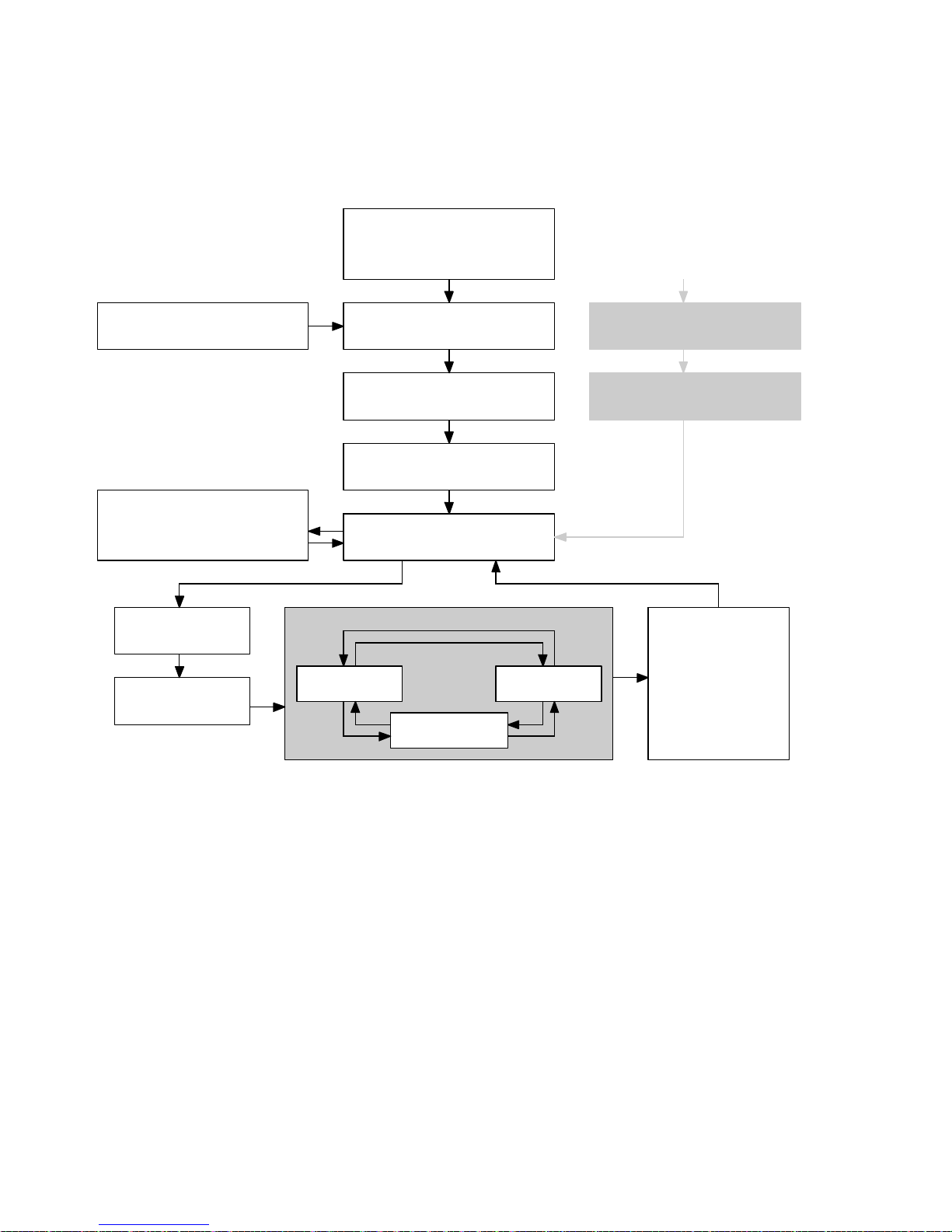
5 Commissioning
5.3.3 Status diagram of the motor controller
The status diagram shows the basic functions of the motor c ontroller. Detailed information regarding
the controller functions can be found in the respective operating modes.
–PowerON/
– FCT: Restart controller
All statuses
Firmware file
Device data (FCT)
Parameter file (.DCO)
Enable output
stage
Enable controller
Bootloader
Initialization
Intermediate circuit precharge
(CMMS-AS/CMMD-AS)
Ready for operation
Controller operating mode
Position
Rotational
speed
Error status
Acknowledge error
Block output stage
and controller
Current
Fig. 5.10 Status diagram of the motor c ontroller
96 Festo – GDCP-CMMS/D-FW-EN – 1404NH – English
Page 97
5 Commissioning
5.3.4 Switching on the power supply (Power ON)
The motor controller is supplied with the following voltage when the power switch is activated (Power
ON). The boot process of the motor controller is started automatically with the Power ON procedure.
Motor controller Control section Power section
CMMS-AS 24 V DC 230 V AC
CMMS-ST 24 V DC 24…48 V DC
CMMD-AS 24 V DC 230 V AC
Tab. 5.9 Overview: Power supply
Warning
Dangerous electrical voltage
Touching live parts will c ause an electric shock, which c an result in death or severe
injuries:
– atanopenslot:
– CMMS: [EXT]
– CMMD: [E XT1/E XT2]
– at the connection or connector:
– Motor [X6] (CMMS)/[X6.1/X6.2] (CMMD)
– Power supply [X9]
1. Equip the open slot [EXT] (CMMS)/[EXT1/EXT2] (CMMD) with the missing module or
cover plate.
2. Install the product in a control cabinet.
Caution
Unexpected movement of the drive
If the following conditions are fulfilled during the Power ON process:
– Output stage enable is enabled (DIN4 = 24 V)[X1.21][X1.1.21/X1.2.21]
– Controller enable is enabled (DI N5 = 24 V)[X1.9][X1.1.9/X1.2.9]
– Setpoint value specified via control interface “Fieldbus/analogue input”
the drive (motor/axis) will start moving; it is then capable of causing crush ing injuries in
the operating area of the drive.
• Make sure the controller enable (DIN5)[X1.9][X1.1.9/X1.2.9] is disabled during the
Power ON process (= 0 V).
Caution
Hot housing surfaces
The housing can reach a temperature of > 80° C during operation, which can cause
burns.
1. Install the product in a control cabinet.
2. Check the temperature of the housing before touching it (e.g. by slowing moving the
back of your hand towards the housing).
Festo – GDCP-CMM S/D-FW-EN – 1404NH – English 97
Page 98

5 Commissioning
Note
Impermissible voltage or overvoltage
The motor controller will be damaged if
1. the voltage exceeds the permissible range.
– Observe the maximum voltage level.
2. the mains phase (L1) is connected to connection [ X9] on the motor controller
“CMMS-AS/CMMD-AS” prior to the neutral conductor (N).
– Use a mains switch with leading neutral conductor (N).
3. the pins of the power supply have incorrect polarity at the connection “Power supply
[X9]”.
– Before switching on, c heck to ensure the power supply is connected to the cor-
4. the connections “Power supply [X9]” and “Motor [X6] [X6.1/X6.2]” are interchanged.
– Before switching on, c heck to ensure the power supply is connected to connec-
5. at the connection “Motor [X6] [X6.1/X6.2]” a motor phase has been short-circuited
with the PE conductor.
– Before switching on, check the motor phases at the connection “Motor
6. the grounding or screening element is insufficient or has not been connected.
– Before switching on, check to ensure the grounding and screening elements are
7. The plug connector is disconnected during operat io n.
– Do not disconnect any plug connectors during operation.
rect pins at connection [X9].
tion [X9] and the motor is c onnected to connection [X6] [X6.1/X6.2].
[X6] [X6.1/X6.2]” for PE short circuit.
connected.
98 Festo – GDCP-CMMS/D-FW-EN – 1404NH – English
Page 99
5 Commissioning
1. Block the controller enable function (DIN5)[X1.9][X1.1.9/X1.2.9] = 0 V.
2. Switch on the power supplies (Power ON).
• CMMS-AS/CMMD-AS: Control section 24 V DC/power section: 230 V AC
• CMMS-ST: Control section 24 V DC/power section: 24…48 V DC
If required, the process for do wnloading the firmware from the memory card c an be
activated via DIL switch [S1.8], switch position = ON.
The Ready LED on the front of the motor controller should now light up.
The following malfunctions can occur:
– The seven-segment display shows an error message (4-digit character sequence
“Exxx”)orawarningmessage(5-digitcharactersequence“–xxx–”) appendix A,
page 216.
– The LED (Ready/Bus (CMMS-ST/CMMD-AS) or CAN (CMMS-AS)) or seven segment
display do not light up.
Perform the following steps:
1. Measure the voltage levels at the input/output of the power supply unit and th e
power switch.
2. Switch off the power supplies (Power OFF).
3. Wait five minutes until the intermediate circuit voltage has discharged.
4. Check the cabling and the connection of the wires at the connection “Power supply”.
5. Switch on the power supplies (Power ON).
5.3.5 Downloading device data (FCT) to the motor controller
1. Connect the PC to the motor c ontroller.
Observe the pin allocation of the RS232 interfaces page 235.
2. Start the Festo Configuration Tool (FCT).
3. Establish an online connection to the motor controller in the FCT.
Theonlinefirmwaredownloadprocesscanbeexecutedifrequired.
4. S tart downloading the device data ( FCT) page 89
Festo – GDCP-CMM S/D-FW-EN – 1404NH – English 99
Page 100
5 Commissioning
5.3.6 Enabling the motor controller via digital inputs
When the output stage enable (DIN4) and controller enable (DIN 5) are activated, the specifications
issued by the controller are carried out by the drive.
Caution
Unexpected movement of the drive
If the following conditions are fulfilled:
– Activate output stage enable (DIN4 = 24 V)[ X1.21][X1.1.21/X1.2.21]
– Activate controller enable (DIN5 = 24 V)[ X1.9][X1.1.9/X1.2.9]
– Setpoint value specified via control interface “Fieldbus/analogue input”
the drive (motor/axis) will start moving; it is then capable of causing crush ing injuries in
the operating area of the drive.
• Make sure that no personnel are in the operating area of the drive.
• Make sure that the motor controller is only controlled by one control interface (master control).
Caution
Defective safety function STO (Safe Torque Off)
If the safety function at connection [X3][X3.1/X3.2] is bypassed, it means the motor
controller cannot be deactivated in the event of an emergency via safety components
(e.g. emergency off switch with safety switching device), which can result in crushing
injuries within the operating area of the drive.
• Parameterise the motor controller with the Festo Configuration Tool (FCT) before the
controller enable is enabled (DI N5)[X1.9][ X1.1.9/X1.2.9] (= 24 V).
• Bypassing of safety equipment is impermissible.
Recommendation for initial start-up without safety equipment:
– Minimum circuitry with emergency stop switching device at connection
[X3][X3.1/X3.2]
– Two-channel switch-off via control ports R EL [ X3.2][ X3.1.2/X3.2.2] and the out-
put stage enable (DIN4)[X1.21][X1.1.21/X1.2.21].
100 Festo – GDCP-CMMS/D-FW-EN – 1404NH – English
 Loading...