

Page 1
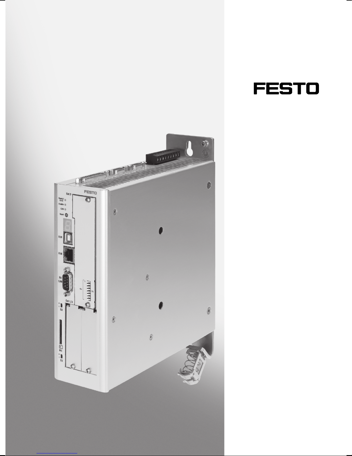
Motor controller
CMMP-AS-...-M3
Description
Functional
description
(firmware).
for motor controller
CMMP-AS-...-M3
FW: 4.0.1501.1.0
760330
1203NH
Page 2
CMMP-AS-...-M3
Translation of the original instructions
GDCP-CMMP-M3-FW-EN
Windows
PROFIBUS
®
,PHOENIX®,CiA®,CANopen®, Bec khoff®,Rockwell®, D eviceNET®,EtherCAT®,
®
, Heidenhain®,EnDat®,HIPERFACE®,Stegmann®,Yaskawa®,CANopen®are registered
trademarks of the respective trademark owners in certain countries.
Identification of hazards and instructions on how to prevent them:
Warning
Hazards that can cause death or serious injuries.
Caution
Hazards that can cause minor injuries or serious material damage.
Other symbols:
Note
Material damage or loss of function.
Recommendations, tips, references to other documentation.
Essential o r useful accessories.
Information on environmentally sound usage.
Text designations:
• Activities that may be carried out in any order.
1. Activities that should be carried out in the order stated.
– General lists.
2 Festo – GDCP-CMMP-M3-FW-EN – 1203NH
Page 3

CMMP-AS-...-M3
Table of contents – CMMP-AS-...-M3
1 Safety and requirements for product use 8......................................
1.1 Safety 8..................................................................
1.1.1 Safety instructions for commissioning, repair and de-commissioning 8...........
1.1.2 Protection against electric shock through protective extra-low voltage (PELV). 9...
1.1.3 Designated use 9.....................................................
1.2 Prerequisites for use 10.......................................................
1.2.1 Technical requirements 10...............................................
1.2.2 Qualification of the specialists (requirements for the personnel) 10..............
1.2.3 Range of application and certifications 10...................................
2 Operating modes and functions 11..............................................
2.1 Overview 11................................................................
3 Control interfaces 12.........................................................
3.1 Control interfaces 12.........................................................
3.1.1 Overview of interfaces 12................................................
4 Fieldbus options 13..........................................................
4.1 Supported fieldbuses 13......................................................
4.2 Required I/O c onnection for fieldbus control 14....................................
5Service 15.................................................................
5.1 Supported functions 15.......................................................
5.2 Memory card 15.............................................................
5.2.1 Load firmware via memory card 16.........................................
5.2.2 Load parameter set from memory card 16...................................
5.3 Ethernet (TFTP) 17...........................................................
5.3.1 Load firmware via Ethernet 17............................................
5.3.2 Load parameter set via Ethernet 17........................................
5.3.3 Save parameter set via Ethernet 18........................................
Festo – GDCP-CMMP-M3-FW-EN – 1203NH 3
Page 4

CMMP-AS-...-M3
6Functions 19...............................................................
6.1 Position controller 19.........................................................
6.1.1 Basic principles of the position controller 19.................................
6.1.2 Record selection through I/O 24..........................................
6.1.3 Start of the record selection 24...........................................
6.1.4 Stop of the record selection through “digital halt” 24..........................
6.1.5 Record selection with record continuation 24................................
6.1.6 Modulo positioning 26..................................................
6.2 Homing 28.................................................................
6.2.1 Homing methods 29....................................................
6.2.2 Homing - options 35....................................................
6.2.3 Homing parameters 36..................................................
6.2.4 Secure zero point shift 36................................................
6.2.5 Homing via I/O 37......................................................
6.2.6 Timing diagrams 38.....................................................
6.3 Jog mode 40................................................................
6.3.1 Function 40...........................................................
6.3.2 Process 41............................................................
6.3.3 Jog mode parameters 42................................................
6.4 Teach-in function 44..........................................................
6.5 Setpoint specification 45......................................................
6.5.1 Analogue setpoint 45...................................................
6.5.2 Digital nominal value 47.................................................
6.5.3 Master-slave 51.......................................................
6.5.4 Flying saw 51..........................................................
6.5.5 Scope of functions for cam discs ( C AM) 53..................................
6.6 Second measuring system 53..................................................
6.6.1 Technology 53.........................................................
6.6.2 Example, toothed belt axis 54............................................
6.6.3 Example, spindle axis 54................................................
6.6.4 Function in the controller 54..............................................
6.6.5 Inclusion of a second displacement encoder 55..............................
6.6.6 2nd measuring system at the incremental encoder input [X10] 55................
6.6.7 EGC-...-M at [X10] 56....................................................
6.6.8 2nd measuring system at input [X2A] 57....................................
6.6.9 Commissioning 57......................................................
4 Festo – GDCP-CMMP-M3-FW-EN – 1203NH
Page 5

CMMP-AS-...-M3
6.7 Additional functions 58.......................................................
6.7.1 Encoder emulation 58...................................................
6.7.2 Brake control and automatic brake 59......................................
6.7.3 Position trigger 61.....................................................
6.7.4 Inputs for option “flying measurement” 62..................................
6.7.5 Software limit switch 62.................................................
6.7.6 Input for digital halt 63..................................................
6.7.7 I/O [X1] 63............................................................
6.7.8 Supported encoder systems 71...........................................
7 Dynamic response 73........................................................
7.1 PFC for increased intermediate circuit voltage 73...................................
7.1.1 Switch-on behaviour: 73.................................................
7.1.2 Behaviour under normal operation and control properties 74...................
7.2 Extended sine modulation for increased output voltage 74...........................
7.3 Variable cycle times, current, speed and position controller 75........................
8 Service functions and diagnostic messages 76....................................
8.1 Protective and service functions 76..............................................
8.1.1 Overview 76..........................................................
8.1.2 Phases and mains failure detection with 3-phase motor controllers 76............
8.1.3 Overload current and short-circuit monitoring 76.............................
8.1.4 Overvoltage monitoring for the intermediate circuit 77.........................
8.1.5 Temperature monitoring for the heat sink 77.................................
8.1.6 Monitoring of the motor 77...............................................
8.1.7 I2t monitoring 77......................................................
8.1.8 Power monitoring for the brake chopper 77.................................
8.1.9 Commissioning status 78................................................
8.1.10 Rapid discharge of the intermediate circuit 78...............................
8.2 Operating mode and error messa ges 78..........................................
8.2.1 Operating mode a nd error display 78.......................................
8.2.2 Seven-segment display 79...............................................
8.2.3 Acknowledgement of error messages 80....................................
8.2.4 Diagnostic messages 80.................................................
A Diagnostic messages 81......................................................
Festo – GDCP-CMMP-M3-FW-EN – 1203NH 5
Page 6

CMMP-AS-...-M3
Instructions on this description
This documentation is intended to help you safely work with the motor controllers of the series
CMMP-AS-…-M3. It includes safety instructions that must be observed.
Refer to the documentation for the CMMP-AS product family for further information Ta b. 1 .
• Unconditionally observe the general safety regulations for the CMMP-AS-...-M3.
The general safety regulations for the CMMP-AS-...-M3 can be found in the description
Hardware, GDCP-CMMP-AS-M3-HW-..., see Tab. 1.
Tar g et g rou p
This description is intended exclusively for tec hnicians trained in control and automation technology,
who have experience in installation, commissioning, programming and diagnosing of positioning systems.
Service
Please consult your regional Festo contact if you have any technical problems.
Product identification, versions
This description refers to the following v ersions:
– Motor controller CMMP-AS-...-M3 from Rev. 01
– Firmware from Version 4.0.1501.1.0
– FCT plug-in CMMP-AS from Version 2.0.x.
This description does not apply to the older variants CMMP-AS-...
Note
With newer firmware versions, check whether there is a newer version of this description available: www.festo.com
6 Festo – GDCP-CMMP-M3-FW-EN – 1203NH
Page 7

CMMP-AS-...-M3
Documentation
You will find additional information on the motor controller in the following documentation:
User documentation on the motor controller CMMP-AS-...-M3
Name, type Contents
Hardware description,
GDCP-CMMP-M3-HW-...
Mounting and installation for all variants/power classes
(1-phase, 3-phase), pin assignments, error messages,
maintenance.
Function descriptions,
GDCP-CMMP-M3-FW-...
Description FHPP,
GDCP-CMMP-M3-C-HP-...
Instructions on commissioning + functional description
(firmware). Overview of fieldbus, safety engineering.
Control and parameterisation of the motor controller through
the Festo pro file FHPP with the following fieldbuses: CANopen,
PROFIBUS, DeviceNet, EtherCAT, PROFINET, Ethernet/IP.
Description CiA 402 (DS 402),
GDCP-CMMP-M3-C-CO-...
Control and parametrisation of the motor controller through the
device profile CiA 402 (DS402) with the following fieldbuses:
CANopenand EtherCAT.
Description CAM-Editor,
Cam disc function (CAM) of the motor controller.
P.BE-CMMP-CAM-SW-...
Description safety module,
GDCP-CAMC-G-S1-...
Functional safety engineering for the motor controller with the
safety function STO.
Help for the FCT plug-in CMMP-AS User interface and functions of the CMMP-AS plug-in for the
Festo Configuration Tool.
www.festo.com
Tab. 1 Documentation on the motor controller CMMP-AS-...-M3
Festo – GDCP-CMMP-M3-FW-EN – 1203NH 7
Page 8

1 Safety and requirements for product use
1 Safety and requirements for product use
1.1 Safety
1.1.1 Safety instructions for commissioning, repair and de-commissioning
Warning
Danger of electric shock.
– When modules or cover plates are not mounted on the slots Ext1 … Ext3.
– When cables are not mounted to the plugs [X6] and [ X9] .
– When connecting cables are disconnected when powered.
Touching live parts causes severe injuries and can lead to death.
The product may only be operated in a built-in status and when all protective measures
have been initiated.
Before touching live parts during maintenance, repair and cleaning work and when there
have been long service interruptions:
1. Switch off power to the electrical equipment via the mains switch and secure it
against being switched on again.
2. After switch-off, wait at least 5 minutes discharge time and chec k that power is
turned off before accessing the controller.
The safety functions do not protect against electric shock but only against dangerous
movements!
Note
Danger from unexpected movement of the motor or axis.
– Make sure that the movement does not endanger any people.
– Perform a risk assessment in accordance with the EC machinery directive.
– Based on this risk evaluation, design the safety system for the entire machine, tak-
ing into account all integrated components. This also includes the electric drives.
– Bypassing safety equipment is impe r missible.
8 Festo – GDCP-CMMP-M3-FW-EN – 1203NH
Page 9

1 Safety and requirements for product use
1.1.2 Protection a gainst electric shock through protective extra-low voltage (PELV).
Warning
• Use for the electrical power supply only PELV circuits in accordance with
IEC DIN EN 60204-1 (Protective Extra-Low Voltage, PELV).
Also take into account the general requirements for PELV circuits in accordance with
IEC/DIN EN 60204-1.
• Use only power sources which guarantee reliable electrical disconnection of the
operating voltage as per IEC/DIN EN 60204-1.
Through the use of PELV circuits, protection from electric shock (protection from direct and indirect
contact) in accordance with IEC DIN EN 60204-1 is ensured (Electrical equipment of machines. General
requirements).
1.1.3 Designated use
The motor controller CMMP-AS-...-M3 is intended for installation in machines or automated systems
andistobeusedasfollows:
– in a faultless technical condition,
– in original status without unauthorised modifications,
– within the limits of the product defined by the technical data ( appendix A of the documentation
GDCP-CMMP-AS-M3-HW-...),
– in an industrial environment.
Note
In the event of damage caused by unauthorised manipulation or other than intended
use, the guarantee is invalidated and the manufacturer is not liable for damages.
Festo – GDCP-CMMP-M3-FW-EN – 1203NH 9
Page 10

1 Safety and requirements for product use
1.2 Prerequisites for use
• Make this documentation available to the design engineer, installer and personnel responsible for
commissioning the machine or system in which this product is used.
• Make sure that the specifications of the documentation are always complied with. Also consider the
documentation for the other components and modules.
• Take into consideration the regulations applicable for the destination, as well as:
– regulations and standards,
– regulations of the testing organizations and insurers,
– national specifications.
• For emergency stop applications, restart may take place only as intended under the control of a
safety switching device.
1.2.1 Technical requirements
General conditions for the correct and safe use of the product, which must be observed at all times:
• Comply with the connection and environmental conditions specified in the technical data of the
motor controller ( appendix A of the documentation GDCP-CMMP-AS-M3-HW-...) and of all connected components.
Only compliance with the limit values or load limits permits operation of the product in accordance
with the relevant safety regulations.
• Observe the instructions and warnings in this documentation.
1.2.2 Qualification of the specialists (requirements for the personnel)
The device may only be set into operation by a qualified electrotechnician who is familiar with:
– installation and operation of electrical control systems,
– the applicable regulations for operating safety-engineered systems,
– the applicable regulations for acc ident protection and occupational safety, and
– the documentation for the product.
1.2.3 Range of application and certifications
Standards and test values which the product complies with and fulfils can be found in the “Technical
data” section ( appendix A of the documentation GDCP-CMMP-AS-M3-HW-...). The product-relevant
EU directives can be found in the declaration of conformity.
Certificates and the declaration of conformity for this product can be found at
www.festo.com.
10 Festo – GDCP-CMMP-M3-FW-EN – 1203NH
Page 11

2 Operating modes and functions
2 Operating modes and functions
2.1 Overview
The following operating modes are available to support your application.
Operating mode/functions
Profile Positioning
Mode
(Profile Position Mode)
Speed-controlled
operation
(Profile Velocity Mode)
Force/torque
operation
(Profile Force/Torque
Mode)
Homing
(Homing)
Interpolated
positioning mode
(Interpolated position
mode in accordance
with CiA 402)
Description
Operating mode for executing a positioning record ( record selection) or a
positioning task (direct mode). In addition to operation with speed control,
a higher-level position controller (setpoint value generator) is active; it
processes deviations between setpoint position and actual position and
converts it into corresponding setpoint specifications for the speed controller. For position control, the current settings for speed, acceleration, braking deceleration, etc. are taken into account.
Operating mode for executing a positioning record ( direct mode). Regulation in acc ordance with speed setpoint values and profiles. In speed-controller operation, current limitation can be activated through specification
of a force/torque limit value.
Operating mode for executing a positioning record ( direct mode) with
force/torque control (current control). This operating mode permits specification to the controller of an external force/torque setpoint value (relative to the motor current). All specifications on forces/torques refer to the
motor nominal torque or the motor nominal current. Since force/torque are
proportional to the motor c urrent, only the current regulator is activated in
this operating case. In addition, speed limiting can be activated through
specification of a limit value.
Positioning mode with a sequence established through the homing method
for definition of the mechanical reference system (homing point).
Positioning mode with a sequence established through the homing method
for definition of the mechanical reference system (homing point)
– Travelling along trajectory curves
– Coupling of axes for multiple axis systems
– Axis error compensation.
The movement is parameterised for several axes in advance in the shape of
data points (position, speed, time) and loaded into the controllers.
Between the data points, the various axes interpolate independently and
work off the movement profile synchronously in time.
Tab. 2.1 Overview of operating modes
Festo – GDCP-CMMP-M3-FW-EN – 1203NH 11
Page 12

3 Control interfaces
3 Control interfaces
3.1 Control interfaces
Control interfaces Setpoint s pecification via Signal type
Analogue [X1] (±10 V) Analogue signal
Synchronisation [X10] (5 V) A/B – tracking signals (RS422)
CLK/DIR – pulse/direction
CW/CCW – pulse
I/O [X1] (24 V) Digital I/O – signals for control of
record selection and jog mode
Fieldbus CANopen (FHPP/CiA DSP 402)
PROFIBUS-DP (FHPP)
DeviceNet (FHPP)
EtherCAT (FHPP/CiA 402)
EtherNet/IP ( FHPP)
PROFINET (FHPP)
Tab. 3.1 Control interfaces
3.1.1 Overview of interfaces
Control interface
Analogue Analogue setpoint spe-
Synchronisation – Flying saw
I/O – Record selection
Fieldbus Depending on the field-
Function Operation Mode Reference
cification
– Synchronisation
(slave)
– Cam disc
–Jogmode
– Linked position sets
–Homingrun
– Cam disc
bus profile
– Speed adjustment
– Torque regulation
– Chap. 6.5.2
Position c ontrol Chap. 6.1.2
– Speed adjustment
– Torque regulation
– Position control
Chap. 6.5.1
45 ff
47 ff
24 ff
GDCP-CMMPM3-C-HP-...
GDCP-CMMPM3-C-CO-...
Tab. 3.2 In t er fa ce s
12 Festo – GDCP-CMMP-M3-FW-EN – 1203NH
Page 13
4 Fieldbus options
4 Fieldbus options
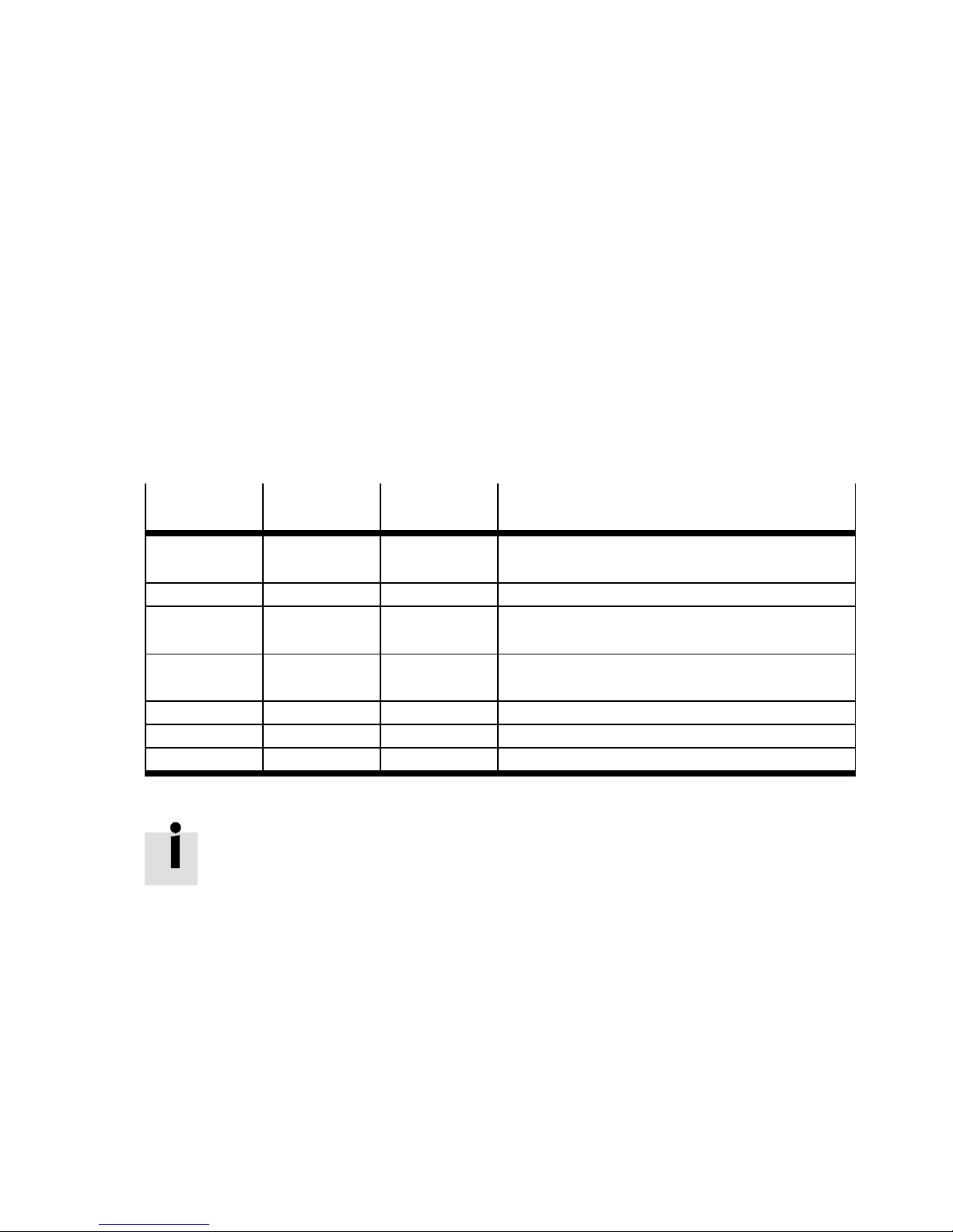
4.1 Supported fieldbuses
Different fieldbuses c an be used with the CMMP-AS-...-M3. Standard with the CMMP-AS -...-M3 is that
the CAN bus is permanently integrated in the motor controller. Optionally, additional fieldbus interfaces
or card modules can be used. But only one fieldbus can be active at any given time.
For all fieldbuses, the Festo Profile for Handling and Positioning (FHPP) has been implemented as the
communication protocol. Additionally, for the CAN bus, the communication protocol based on the
CANopen profile in accordance with the CiA DS-301 and the drive profile in accordance with the CiA 402
have been implemented.
Independent of the field bus, a factor group can be used so that application data can be transferred
into use r-specific units.
Fieldbus
CANopen [X4] — GDCP-CMMP-M3-C-CO-... (CiA 402)
DeviceNet [Ext1] CAMC-DN GDCP-CMMP-M3-C-HP-... (FHPP)
DriveBus [X4] — GDCP-CMMP-M3-C-CO-... (CiA 402)
EtherCAT [Ext2] CAMC-EC GDCP-CMMP-M3-C-CO-... (CiA 402)
PROFIBUS DP [Ext2] CAMC-PB GDCP-CMMP-M3-C-HP-... (FHPP)
PROFINET [Ext2] CAMC-F-PN GDCP-CMMP-M3-C-HP-... (FHPP)
Ethernet/IP [Ext2] CAMC-F-EP GDCP-CMMP-M3-C-HP-... (FHPP)
Tab. 4.1 Fieldbus support
Connection Interface
(type)
Fieldbus support files are included on the CD-ROM in the scope of supply of the motor
controller CMMP-AS-...-M3. Update on www.festo.com/download.
Documentation – type
GDCP-CMMP-M3-C-HP-... (FHPP)
GDCP-CMMP-M3-C-HP-... (FHPP)
Festo – GDCP-CMMP-M3-FW-EN – 1203NH 13
Page 14
4 Fieldbus options
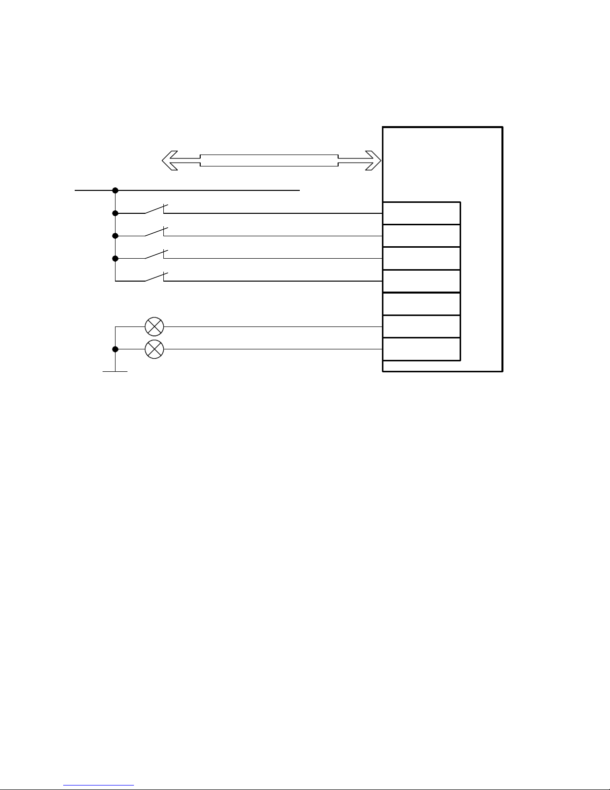
4.2 Required I/O connection for fieldbus control
Fieldbus
CMMP-AS-...-M3
24 V DC
Controller enable / DIN5
Output stage enable / DIN4
Limit switch0 / DIN61)
Limit switch1 / DIN71)
Operating status / DOUT0
Default - motion complete / DOUT1
The connection plan shows the switch position in the active operating state.
1) The limit switches are set by default to N/C contact (configuration over FCT)
Fig. 4.1 Connection diagram: required I/O interface
X1/Pin
9
21
22
10
24
12
14 Festo – GDCP-CMMP-M3-FW-EN – 1203NH
Page 15
5Service
5Service
5.1 Supported functions
Firmware Parameter file
Medium
Memory card X – X X
Ethernet (TFTP) X – X X
FCT (Ethernet/USB) X – X X
Tab. 5.1 Supported functions
5.2 Memory card
Characteristic Description
load save load save
Functions Copying (loading) a parameter set from the memory card to the
CMMP-AS-...-M3.
Copying (saving) a parameter set from the CMMP-AS-...-M3 to the
memory card.
Copying (loading) a firmware from the memory card to the
CMMP-AS-...-M3.
Supported card types MMC1)(version 3)
SD1)(version 1 and 2)
SDHC1)(from class 2)
Supported file systems FAT16
FAT32
Format filename 8.3
1) Recommended are industry-suitable cards from the Festo accessories programme.
Tab. 5.2 Characteristics of the memory card
Note
The filenames may only consist of upper case letters.
If lower case letters are used when the filename is issued, Windows automatically saves
the file in the file format for long filenames!
Filename extension
.mot Firmware file FW_CMMP-AS-M3_4P0_2P0.MOT
.dco Parameter file CMMP01.DCO
.txt Info file INFO.TXT
Tab. 5.3 Filename extension
Festo – GDCP-CMMP-M3-FW-EN – 1203NH 15
Description Example
Page 16

5Service
5.2.1 Load firmware via memory card
Procedure for loading firmware via the memory card:
1. Make sure that the output stage enable is switched off.
2. Shift the switch [S3] onto ON.
3. Insert the memory card with the firmware into the module [ M1].
4. Actuate the reset button
5. The motor controller checks whether a memory c ard is plugged in and includes loadable firmware.
Memory card plugged in and valid firmware version firmware is loaded.
6. The firmware update is signaled through “F.” on the digit representation with 7 segments.
7. The motor controller automatically starts the firmware by triggering a RESET.
8. The motor controller searches for the newest parameter file on the memory c ard and loads it into
the motor controller.
9. Shift the switch [S3] to ON.
Errors may occur in firmware download. Possible causes for this are:
– Memory card not plugged in
– Invalid firmware version
– Firmware file includes lower case letters
If one of these points is applicable, the firmware update is cancelled and an error reported.
The decimal point in the digit representation with 7 segments is also displayed in case of
errors that were detected or triggered through the bootloader.
If no memory card was found or there is no parameter set on the memory card, the parameter set valid before the firmware download is loaded.
If no memory card was found or there is no firmware on the memory card:
– Error 29-0 is reported
– The boot process is stopped (displayed through a decimal point on the digit repres-
entation with 7 segments).
It is recommended to have only one firmware file at a time on the SD card. In the case of
several files, the newest one is always loaded!
If the newest file is already included on the motor controller, no firmware update is carried out.
5.2.2 Load parameter set from memory card
Parameterisation in the FCT can establish whether a parameter set is loaded from the memory c ard
when the motor controller is reset. Possible options:
– Use the newest parameter file.
– Load parameter file with specific name.
Loading of the parameter set is shown with a “d” on the digit representation with 7 segments.
16 Festo – GDCP-CMMP-M3-FW-EN – 1203NH
Page 17

5Service
5.3 Ethernet (TFTP)
5.3.1 Load firmware via Ethernet
Firmware can be loaded via the Ethernet interface [ X18].
For computers that use Windows Vista or Windows 7 as operating system, the TFTP client and ports
must be specially activated or opened for the firewall.
Procedure with the program TFTP.EXE:
1. Make sure that the output stage enable is switched off.
2. Start the program CMD.EXE
3. Call up the program TFTP.EXE with the following syntax
4. tftp -i <ip-address> PUT <FILENAME.MOT>
<ip-address> = IP address of the motor controller
<FILENAME.MOT> = Filename of the firmware
5. The PC copies the firmware file locally into the motor controller.
6. The motor controller checks whether the firmware is appropriate.
7. If yes, the firmware version is checked.
Firmware version is th e same -> error message “File already exists”
Firmware version is different -> Firmware update is started.
8. The firmware update is signaled through “F.” on the digit representation with 7 segments.
9. The motor controller automatically starts the firmware by triggering a RESET.
A firmware download is also possible if the firmware programming has been cancelled
and the controller does not have valid firmware. But observe that the controller in this
case may have a different IP address (if it procures it through DHCP).
Errors may occur in firmware download. Possible causes for this are:
– The firmware to be loaded is unsuitable for the device! (see FW header)
– Faulty S record received.
– Error when programming the S record in FLASH.
The decimal point in the digit representation with 7 segments is also displayed in case of
errors that were detected/triggered through the bootloa der.
5.3.2 Load parameter set via Ethernet
A parameter set can be loaded via the Ethernet interface [X18].
For computers that use Windows Vista or Windows 7 as operating system, the TFTP client and ports
must be specially activated or opened for the firewall.
Procedure with the program TFTP.EXE:
1. Make sure that the output stage enable is switched off.
2. Start the program CMD.EXE
3. Call up the program TFTP.EXE with the following syntax
Festo – GDCP-CMMP-M3-FW-EN – 1203NH 17
Page 18

5Service
4. tftp -i <ip-address> PUT <FILENAME.DCO>
<ip-address> = IP address of the motor controller
<FILENAME.DCO> = Filename of the parameter set
5. The PC copies the firmware file locally into the motor controller.
6. The motor controller checks the parameter set.
Parameter set is the same -> Parameter set is not loaded
Parameter set is different => Parameter set update is started.
7. The parameter set update is signaled through “d” on the digit representation with 7 segments.
8. The motor controller automatically starts the firmware by triggering a RESET.
During Parameter set download, error 49-0 may occur. Possible causes for this are:
– Formatting error in the DCO file
– Faulty parameters in the DCO file (invalid value).
– Error during parameter access (read or write)
5.3.3 Save parameter set via Ethernet
A parameter set can be stored via the Ethernet interface [ X18].
For computers that use Windows Vista or Windows 7 as operating system, the TFTP client and ports
must be specially activated or opened for the firewall.
Procedure with the program TFTP.EXE:
1. Make sure that the output stage enable is switched off.
2. Start the program CMD.EXE
3. Call up the program TFTP.EXE with the following syntax
4. tftp -i <ip-address> GET <FILENAME.DCO>
<ip-address> = IP address of the motor controller
<FILENAME.DCO> = Filename of the parameter set
5. Through the GET command, creation of the DCO file is started.
Creation of the DCO file takes approx. 1-2 seconds. Therefore, the first GET command is
answered with the error message “File not found”.
6. Enter the command “tftp -i <ip-address> GET <FILENAME.DCO>” again.
7. The motor controller copies the parameter set into the PC.
18 Festo – GDCP-CMMP-M3-FW-EN – 1203NH
Page 19

6Functions
6 Functions
6.1 Position controller
6.1.1 Basic principles of the position controller
In t he positioning mode, a certain position is specified to which the motor must move. The current position is obtained from the information gained from the internal encoder analysis. The position deviation
is processed in the position controller and passed on to the speed regulator.
The integrated position controller allows jerk-limited or time-optimised positioning, either relative to
the c urrent position or absolute with respect to a reference point. It provides setpoint values to the
position controller and, to improve the dynamic response, also to the speed regulator.
With absolute positioning, travel occurs directly to a defined target position. With relative positioning,
travel occurs around a parameterised path. The positioning range of 2
relative positioning can occur as often as desired in a given direction. After the positioning range is
reached, the actual position runs over it without triggering an error. This overrunning must be taken into
account by the controller.
The positioning controller is parameterised via a target table. This contains entries for parameterising a
target via a communication interface and also target positions that can be access via the digital inputs.
The positioning method, travel profile, acceleration and braking times, and maximum speed can be
specified for every entry. All targets can be pre-parameterised. Positioning then only requires an entry
to be selected and a start command to be issued.
In the motor controller CMMP-AS-...-M3, 255 position records can be stored.
All position records have the following possible settings:
– Mode (relative or absolute positioning)
– T arget position
– Speed
– Acceleration
– Braking deceleration
– Smoothing
– Start Condition
– Direction of rotation with modulo positioning
– Step criterion
– Record at digital input NEXT1
– Record at digital input NEXT2
– Ignore stop input
– End speed
– Synchronisation
– Remaining path message
– Torque feed forward
– T orque limitation
–StartDelay
32
full rotations ensures that
Festo – GDCP-CMMP-M3-FW-EN – 1203NH 19
Page 20

6Functions
The positioning records can be addressed via digital inputs, fieldbus or the parameterisation software
FCT.
Absolute positioning linear/rotative axis
Here, the positioning target is moved to regardless of the current position. With absolute positioning
the target position is a fixed (absolute) position relative to the zero point or reference point.
Absolute positioning, modulo axis
The target position of the positioning record is travelled to with modulo correction. Example: 490°
for modulo 360, the axis is positioned to 130°.
Relative positioning, linear/rotative axis
With relative positioning, the target position is obtained by adding a value to the current position. Referencing is necessary to bring the drive into a defined position.
Concatenation of relative positioning can be used to continuously position in the same direction, such
as for a trimming unit or conveyor (incremental dimensions). The following options are available:
– Relative reference to the last target position
– Relative reference to the current position (actual position)
Relative positioning, modulo axis
The target position of the positioning record is not travelled to with modulo correction. Example: 490°
, the axis travels positively around 490°.
Positioning with analogue setpoint
The target position is determined through the analogue setpoint specification at AIN0 [X1]. The following options are available:
– Absolute reference to the project zero point
– Relative reference to the last target position
– Relative reference to the current position
– Continuous positioning c orresponding to the analogue setpoint specification (joystick function)
Speed
The maximum speed at which movement to the position is to take place.
Acceleration
Setpoint value of acceleration for the positioning record.
Deceleration
Setpoint value of the positioning record deceleration.
Smoothing
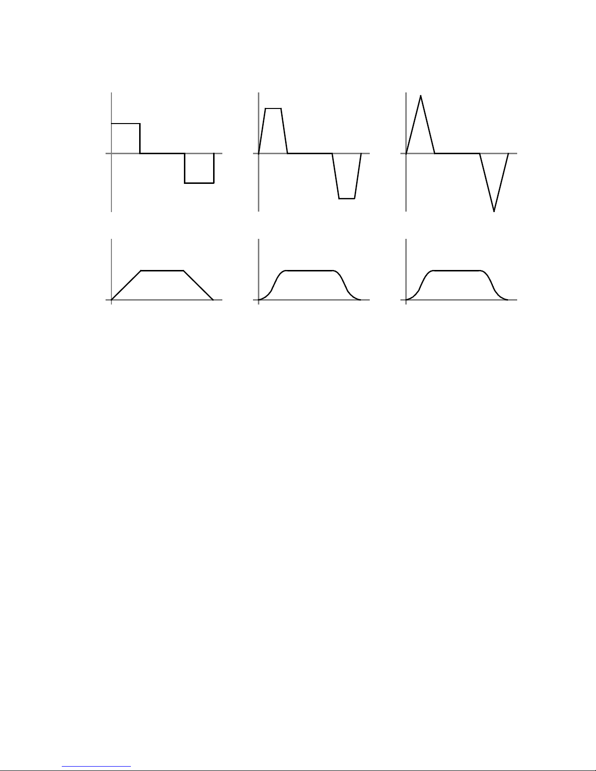
With travel profiles, a distinction is made between time-optimised and jerk-limited positioning. With
time-optimised positioning, motion occurs with the maximum specified acceleration and braking. The
drive moves to the target in the shortest possible time, the speed sequence is trapezoidal and the acceleration sequence square. With jerk-limited positioning, the acceleration is trapezoidal and the speed
curve is third-order. Since the acceleration constantly changes, the drive moves in a manner that is
especially gentle to the mechanics.
20 Festo – GDCP-CMMP-M3-FW-EN – 1203NH
Page 21
6Functions
a(t) a(t) a(t)
123
ttt
v(t) v(t) v(t)
t1 t2 t3
1 Time-optimised = 0 %
3 Jerk-free = 100 %
2 Jerk-limited
Fig. 6.1 Positioning profiles
Start Condition
Start of a new positioning record with ongoing movement
– Ignore: Start command is not carried out
– Wait: Terminate current record and then start selected record
– Interrupt: Cancel current record and immediately start new record.
Direction
Establishment of the direction of rotation when modulo positioning is active in the mode “Direction of
rotation from position record” is defined here. The following settings are possible:
– Positive: The direction of movement of the axis is always positive
– Negative: The direction of movement of the axis is always negative
– Auto: The direction of travel is determined automatically from the current position, target position
and additional options (absolute, relative, relative related to last target, etc .).
Command (record continuation)
Record continuation consists of a defined sequence of positioning records. Each positioning re cord can
be used as a reco rd sequence through parameterisation of its subsequent position and continuation
condition. The number of positions in a record sequence is limited only by the total number of positions
available.
The continuation condition for the next positioning record is determined through the “Command”
column of the positioning record table. The following commands are available:
Festo – GDCP-CMMP-M3-FW-EN – 1203NH 21
Page 22

6Functions
Command Function
END No continuation takes place; the record sequence ends with this positioning
record.
GoFP1 Continuation takes place after the current positioning record is completed and is
always to the subsequent positioning record specified in Next1 (without evaluation of the digital input NEXT1).
IgnUTP Continuation only takes place after completion of the current positioning record
and a subsequent rising edge at the digital input NEXT1 or NEXT2 to the associated specified subsequent positioning record Next1 or Next2. Signal edges at
NEXT1 and NEXT2 are ignored during the current positioning motion.
GoImm Continuation takes place immediately in the event of a rising edge at the digital
input NEXT1 or NEXT2 to the associated specified subsequent positioning record
NEXT1 or NEXT2.
Movement is not continued to the target position of the current positioning record.
GoAtp Continuation only takes place after the current positioning record is completed.
During the current positioning movement, the most recently detected rising edge
at the digital input NEXT1 or NEXT2 decides the associated subsequent positioning record NEXT1 or NEXT2 to which continuation is made.
This decision is made by the first detected edge after th e current positioning
motion is completed.
Additional pa rameters:
Ign. Stop Ignore STOP input.
The signal of the digital input is ignored for this positioning record.
End speed Specifies the end speed of the positioning record. Default = 0 (rest when the
setpoint position is reached). The current positioning record is ended at the
target position with the defined end speed. This enables the drive to execute a
subsequent record with the same positioning speed without reducing the speed.
Tab. 6.1 Commands for record continuation
NEXT1/NEXT2
Subsequent positions of a positioning record for record continuation through positioning record
number a nd digital inputs. Execution (travel to the subsequent position) corresponds to the logic
operation of the digital inputs NEXT1 and NEX T2 through step enabling condition of the positioning
record. The digital inputs N EXT1 and NEXT2 are evaluated only through the step enabling conditions
GoImm, IgnUTP, GoATP.
Synchronisation
The “Sync.” (synchronisation) column is only shown when using the “Flying Saw” function.
If the “Flying Saw” function is active, synchronisation can be activated or deactivated by starting
positioning records. When synchronisation is active, the position of the encoder (master) selected for
the synchronisation is locked onto the setpoint position value. The drive thus follows the changes in
position of the master drive.
22 Festo – GDCP-CMMP-M3-FW-EN – 1203NH
Page 23

6Functions
The following settings are possible:
Command
Function
Sync Synchronisation is activated when positioning is started, if it was not already. If
the master is not stationary when positioning starts, the offset that occurs will
be made up in a controlled manner. The positioning speed used for this corresponds t o the speed of the master plus the positioning speed entered in the positioning record as an excessive increase in speed. The entries of the star ted positioning record are likewise used for the accelerations.
Sync Out Synchronisation is deactivated when positioning is started, if it was not already.
Positioning starts with the current synchronous positioning speed ( rotational
speed of the master). This results in controlled desynchronisation.
No Sync Synchronisation is deactivated when positioning is started, if it was not already.
Positioning starts with the values for speed and acceleration entered in the positioning record.
Tab. 6.2 Commands for synchronisation
Remaining Distance
Enter the amount for the remaining distance message.
TFF (torque feed forward)
This value is used to permit the motor greater dynamic response during acceleration when large loads
are moved. The current required for approaching is increased by the set percentage (related to the
nominal current of the motor) after the positioning record is started. The result is a higher starting
torque that facilitates greater dynamic response. The value is determined experimentally .
Torque limitation
During standard positioning, the torque is limited only by the set nominal or peak currents. Torque limitation provides another way of further limiting the torque during active positioning. The value should be
less than the set nominal current.
Start Delay
Waiting time until positioning starts.
Festo – GDCP-CMMP-M3-FW-EN – 1203NH 23
Page 24
6Functions
6.1.2 Record s election through I/O
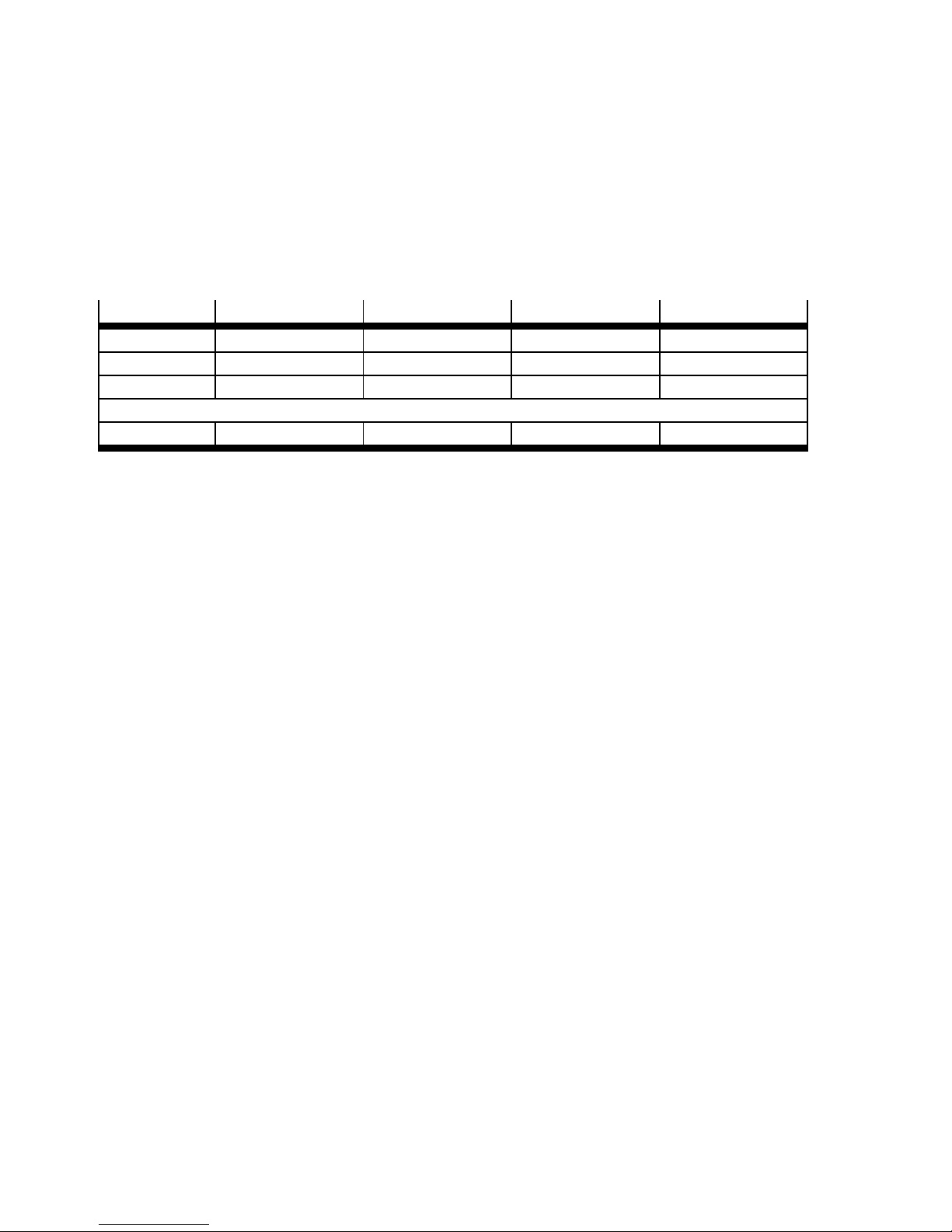
To address a command record, a record number with up to 8 bits can be agreed and thus the reference
travel (record 0) and 255 command records addressed (via F HPP 250).
In the default setting without I/O extension and without reconfiguration, the motor controller
CMMP-AS-...-M3 allocates 4 digital inputs DIN0 … DIN3 for a maximum of 15 command records. The
respective positioning record is selected via the binary code of the record numbers 1 … 15.
Record
Record 0
1)
Bit 3 Bit 2 Bit 1 Bit 0
0 0 0 0
Record 1 0 0 0 1
Record 2 0 0 1 0
…
Record 15 1 1 1 1
1) Homing
Tab. 6.3 Bit pattern of the record number
The following I/O expansions are possible:
– 4 additional inputs (DIN10 … 13) through corresponding reconfiguration of digital outputs or ana-
logue inputs possible with FCT
– Two extension modules, each with 8 additional digital inputs and out puts (accessories type
CAMC-D-8E8A).
6.1.3 Star t of the rec ord selection
After setting the START signal, the number of the selected positioning record is taken over and the drive
carries out the record.
6.1.4 Stop of the record selection through “digital halt”
The digital halt stops in positioning mode with the parameterised ramp of the positioning record.
After that, the drive is controlled ( brake is opened).
6.1.5 Record s election with record continuation
Function
Record continuation consists of a defined sequence of positioning records. Each positioning re cord can
be used as a reco rd sequence through parameterisation of its subsequent position and continuation
condition. The number of positions in a record sequence is limited only by the total number of positions
available.
Process
The continuation condition for the next positioning record is determined through the “Command”
column of the positioning record table. Through the continuation condition of the positioning records,
the following record continuation sequences can be set:
– Linear sequence with established subsequent position NEXT1 of the positioning record
– Conditional branching to the subsequent position NEXT1 or NEXT2 of the current positioning record
– cyclical process ( repetition of the sequence, infinite loop...).
24 Festo – GDCP-CMMP-M3-FW-EN – 1203NH
Page 25

6Functions
Continuation takes place dependent on:
– the continuation c ondition set for the current positioning record,
– the logical status of the digital inputs with the assignment NEXT1 or NEXT2.
Starting the process
The start is made through:
– a rising edge at the digital input “travel to the STAR T position”
Stopping the process
Record continuation is terminated when
– a positioning record is executed with the option END or
– a stop signal is present at the STOP input.
The Stop signal at the STOP input is not executed if the continuation condition “StopIgn”
has been set for the current positioning record.
Sequence control
DIN
Function
START Set positioning records for the Home or Start position.
HOME
When the START signal is set (0
(1
}
0). The MC signal (Motion Complete) is reset (1}0),; the drive carries out the
homing run. When the START signal is reset (1
signal (0
(0
}
}
1). After completion of the positioning job, the MC signal is set again
1).
}
1), confirmation follows via the ACK signal
}
0), c onfirmation follows via the ACK
NEXT1/2 Subsequent positions of a positioning record for record continuation through posi-
tioning record number and digital inputs.
Execution (travel to the subsequent position) corresponds to the logic operation of
the digital inputs NEXT1 and NEXT2 through the step enabling condition of the positioning record.
The digital inputs NEXT1 and NEXT2 are evaluated only through the step enabling
conditions GoImm, IgnUTP, GoATP.
STOP Stop record continuation
0
}
1: Record c ontinuation is stopped. The ongoing positioning is still ended in any
case.
Note: If the positioning record has the setting “StopIgn”, despite the set STOP input
the positioning record of the subsequent position is started.
Combined
START/STOP
The MC signal (Motion Complete) is set (0
0}1: START position of the record continuation is approached.
1
}
0: activates Stop function of record continuation
}
1), the READY signal is reset (1}0).
Tab. 6.4 Sequence control via I/O
Festo – GDCP-CMMP-M3-FW-EN – 1203NH 25
Page 26

6Functions
Example
For positioning record “4”, the following are established as subsequent positions:
– NEXT1 := “19” (Z DIN0
– NEXT2 := “20” (Z DIN1
}
}
1)
1)
Through the I/O configuration, the subsequent positions are logically linked to the digital inputs DIN0
and DIN1. Corresponding to the established continuation condition, the following positioning behaviour results:
Command
Continuation c ondition (example)
END After position 4 is reached, record continuation is ended.
GoFP1 Signal edges 0}1 at input DIN0 or DIN1 are not evaluated. After position 4 is reached,
position 19 is travelled to immediately.
IgnUTP As long as position 4 has not been reached yet, edge changes at DIN0 and DIN1 are
ignored. If position 4 is reached, a rising edge at input
–NEXT1(DIN00
–NEXT2(DIN10
}
1) c auses approach of the target position 19
}
1) an approach of the target position 20.
GoImm Signal edges 0}1 at input DIN0 or DIN1 are evaluated during the positioning pro cess.
With an active positioning edge at input NEXT1 or NEXT2, the ongoing positioning is
cancelled and
–NEXT1(DIN00
–NEXT2(DIN10
}
1) c auses approach of the target position 19
}
1) causes the target position 20 to be approached.
GoATP – As long as position 4 has not been reached yet, edge changes at DIN0 and DIN1 are
recorded; positioning is not interrupted. During the ongoing positioning, first a signal edge appears at DIN0 0
}
1, after that an edge at DIN1 0}1. After target posi-
tion 4 is reached, positioning is started to Pos. 20.
– If position 4 is reached before an edge oc c urs, a rising edge at input:
–NEXT1(DIN00
–NEXT2(DIN10
}
1) c auses approach of the target position 19
}
1) an approach of the target position 20.
Tab. 6.5 Continuation condition (example)
6.1.6 Modulo positioning
“Modulo” positioning can be performed for timed endless movements (e.g. conveyor belts, rotary indexing tables). This enables endless movements to be implemented without losing the position reference to the zero point of the measuring reference system.
Selection for the modulo positioning is possible for the following axis configurations:
– Rotative axis with unlimited positioning range
– User-defined linear axis - type “conveyor belt”
Direction of movement
For modulo positioning, the direction of movement of the positioning motion is specified through the
following selection: In the case of the “Direction of rotation always positive/negative” mode, the setting also applies to setpoints outside the interval (i.e. position specification prefixes are ignored in the
position record table). The “Shortest Patch” se tting only applies for absolute positioning within the
26 Festo – GDCP-CMMP-M3-FW-EN – 1203NH
Page 27

6Functions
specified interval. Outside the interval and for relative positioning, the direction of movement is taken
from the positioning record table.
Observe that with an unlimited drive that always mov es in the same direction, it is possible for the actual position to be overrun. There is no limitation of the range of values.
The actual position is incremented up to overflow.
Option
Shortest path
(for absolute positioning within
the interval)
Direction of rotation from
positioning record
Direction of rotation always
positive
(Absolute and relative
positioning)
Direction of rotation always
negative
(Absolute and relative
positioning)
Range limit positive/negative
(interval)
Function
Both directions of movement are permitted. Positioning takes
place by the shortest path, optimised for direction. Example: The
positioning interval is defined from 0 R … 5 R. The current actual
position is 4.5 R. The new setpoint position is 0.5 R. => The motor
controller does not travel four revolutions in the negative direction
but instead one revolution in the positive direction as this is the
shortest path to reach its destination.
The direction of rotation is not universally defined, but can be individually defined for each positioning record. The following settings
are possible in the positioning record:
positive The direction of movement of the axis is always posit-
ive. (Absolute and relative positioning)
negative The direction of movement of the axis is always negat-
ive. (Absolute and relative positioning)
auto The direction of travel is determined automatically
from the current position, target position and additional options (absolute, relative, relative related to
last target, etc.).
The direction of movement of the axis is always positive.
The direction of movement of the axis is always negative.
By specifying an interval, the actual value only runs through values
within the specified limits. The position range is not influenced by
specifying the interval (unlimited, software limit switch not active).
Tab. 6.6 Options modulo positioning
Festo – GDCP-CMMP-M3-FW-EN – 1203NH 27
Page 28

6Functions
If the actual value exceeds the lower limit of the interval, it assumes the upper limit value.
If the actual value reaches the upper limit of the interval, it displays the lower limit value.
The lower limit of the interval is contained in the range of values; the upper limit does not
belong to this, i.e. the highest value is never shown, as it is physically at the same position as the lowest value. Example: An interval of precisely one revolution is to be defined:
Incorrect: 0 R … 0.99999 R
Correct: 0 R … 1 R.
Note
setpoints outside the interval (incl. the upper interval limit) are always approached
again, even if the drive is already at the position.
Note
When the cam disc function is activated, modulo positioning can only be used for the
master.
6.2 Homing
No homing is required for speed-controlled operation or force/torque operation.
For absolute positioning, homing must be executed and the dimensional reference system defined at initial commissioning. If the drive does not use a multi-turn absolute encoder, homing must be repeated at each switch-on or reset.
To be able to travel to an absolute, unique position in the positioning range, the drive must be referenced to a measuring reference system.
Homing of the drive comprises:
–Homing
– Establishment of the axis zero point
– Definition of the dimensional reference system.
With homing, t he correct zero position is determined by means of a reference signal. The reference
signal trigger defines the reference point of the dimensional reference system. The reference point is
the absolute point of reference for the axis zero point. In the factory setting, the axis zero point = project zero point.
The reference signal supplies, for example, a switch that is triggered at a known, unique position on the
travel path. Also, dependent on the motor encoder, additional signals (e.g. encoder zero track) can be
evaluated to increase accuracy. You establish the used signals via the homing method.
28 Festo – GDCP-CMMP-M3-FW-EN – 1203NH
Page 29

6Functions
6.2.1 Homing methods
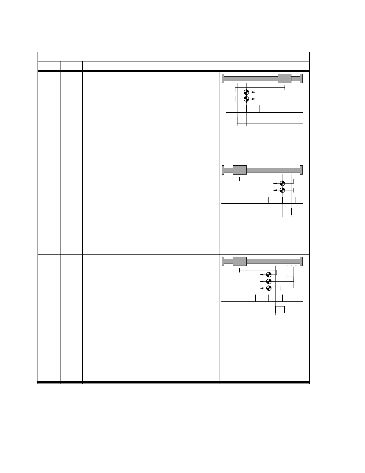
The homing methods are oriented on CiA 402.
With some motors (those with absolute encoders, single- or multi-turn), the drive may be
permanently referenced. In such cases, methods involving homing to an index pulse
(= zero pulse) might not cause homing to be carried out; rather the drive will move directly to the axis zero point (if it has been entered in the parameters).
The drive homes against a stop, a limit switch or a reference switch. The motor current increases when
the drive reaches a stop. Since the drive must not continuously home against the stop, it must move at
least one millimetre back in to the stroke range.
Procedure:
1. Search for the homing point corresponding to the configured method.
2. Run relative to the reference point around the “Offset axis zero point”.
3. Set at the axis zero point: Current position = 0 – offset project zero point.
Festo – GDCP-CMMP-M3-FW-EN – 1203NH 29
Page 30
6Functions
Homing methods
hex dec Desc riptio n
01h 1 Negative limit switch with index pulse
1)
1. If negative limit switch inactive:
Run at search speed in negative direction to
the negative limit switch.
2. Travel at creep speed in a positive direction
until the limit switch becomes inactive, then
continue to the first index pulse. This position
is taken as the homing point.
3. If this is parameterised: travel at positioning
speed to the axis zero point.
02h 2 Positive limit switch with index pulse
1)
1. If positive limit switch inactive:
Run a t search speed in positive direction to
the positive limit switch.
2. Travel at creep speed in negative direction until the limit switch becomes inactive, then continue to the first index pulse. This position is
taken as the homing point.
3. If this is parameterised: travel at positioning
speed to the axis zero point
07h 7 Reference switch in positive direction with index
1)
pulse
1. If reference switch inactive:
Travel at search speed in positive direction to
the reference switch.
If the stop or limit switch is approached:
Travel at search speed in positive direction to
the reference switch.
2. Travel at creep speed in negative direction until the homing switch becomes inactive, then
continue to the first index pulse. This position
is taken as the homing point.
3. If this is parameterised: travel at positioning
speed to the axis zero point.
Index pulse
Negative limit switch
Index pulse
Positive limit switch
Index pulse
Homing Switch
1) Only possible for motors with encoder/resolver with index pulse.
2) Limit switches are ignored during travel to the stop.
3) Since the axis is not to remain at the stop, the travel to the axis zero point must be parameterised and the axis zero point offset
mustbe≠0.
30 Festo – GDCP-CMMP-M3-FW-EN – 1203NH
Page 31
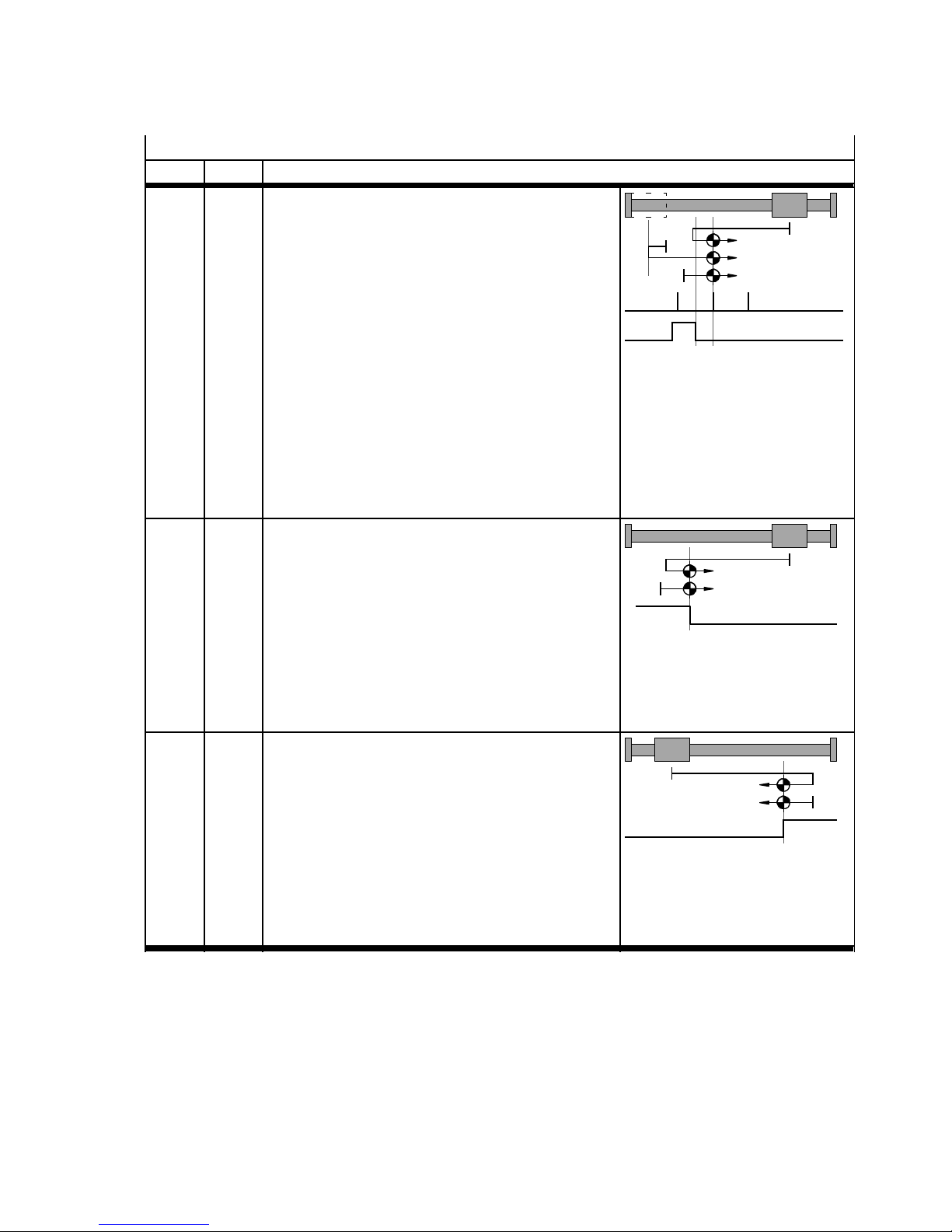
6Functions
Homing methods
hex Descriptiondec
0B 11 Reference switch in negative direction with index
1)
pulse
1. If reference switch inactive:
Travel at search speed in negative direction to
the reference switch.
If the stop or limit switch is approached:
Travel at search speed in positive direction to
the reference switch.
2. Travel at creep speed in positive direction until
the homing switch becomes inactive, then
continue to the first index pulse. This position
is taken as the homing point.
3. If this is parameterised: travel at positioning
speed to the axis zero point.
11h 17 Negative limit switch
1. If negative limit switch inactive:
Run at search speed in negative direction to
the negative limit switch.
2. Travel at creep speed in positive direction until
the limit switch becomes inactive. This position is taken as the homing point.
3. If this is parameterised: travel at positioning
speed to the axis zero point.
12h 18 Positive limit switch
1. If positive limit switch inactive:
Run a t search speed in positive direction to
the positive limit switch.
2. Travel at creep speed in negative direction until the limit switch becomes inactive. This position is taken as the homing point.
3. If this is parameterised: travel at positioning
speed to the axis zero point.
Index pulse
Homing Switch
Negative limit switch
Positive limit switch
1) Only possible for motors with encoder/resolver with index pulse.
2) Limit switches are ignored during travel to the stop.
3) Since the axis is not to remain at the stop, the travel to the axis zero point must be parameterised and the axis zero point offset
mustbe≠0.
Festo – GDCP-CMMP-M3-FW-EN – 1203NH 31
Page 32
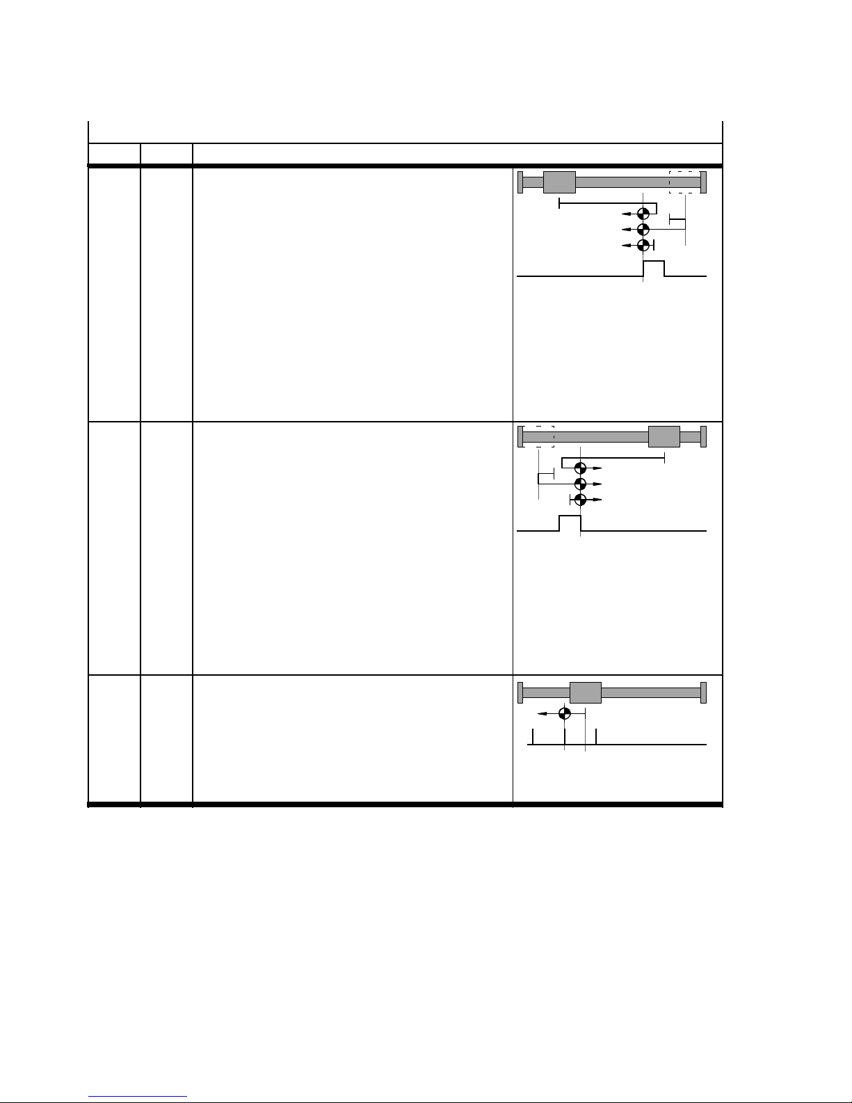
6Functions
Homing methods
hex Descriptiondec
17h 23 Reference switch in positive direction
1. If reference switch inactive:
Travel at search speed in positive direction to
the reference switch.
If the stop or limit switch is approached:
Travel at search speed in positive direction to
the reference switch.
2. Travel at creep speed in negative direction until the homing switch becomes inactive. This
position is taken as the homing point.
3. If this is parameterised: travel at positioning
speed to the axis zero point.
1Bh 27 Referenceswitchinnegativedirection
1. If reference switch inactive:
Travel at search speed in negative direction to
the reference switch.
If the stop or limit switch is approached:
Travel at search speed in positive direction to
the reference switch.
2. Travel at creep speed in positive direction until
the homing switch becomes inactive. This position is taken as the homing point.
3. If this is parameterised: travel at positioning
speed to the axis zero point.
21h 33 Index pulse in negative direction
1)
1. Travel at creep speed in negative direction until the index pulse. This position is taken as
the homing point.
2. If this is parameterised: travel at positioning
speed to the axis zero point.
Homing Switch
Homing Switch
Index pulse
1) Only possible for motors with encoder/resolver with index pulse.
2) Limit switches are ignored during travel to the stop.
3) Since the axis is not to remain at the stop, the travel to the axis zero point must be parameterised and the axis zero point offset
mustbe≠0.
32 Festo – GDCP-CMMP-M3-FW-EN – 1203NH
Page 33
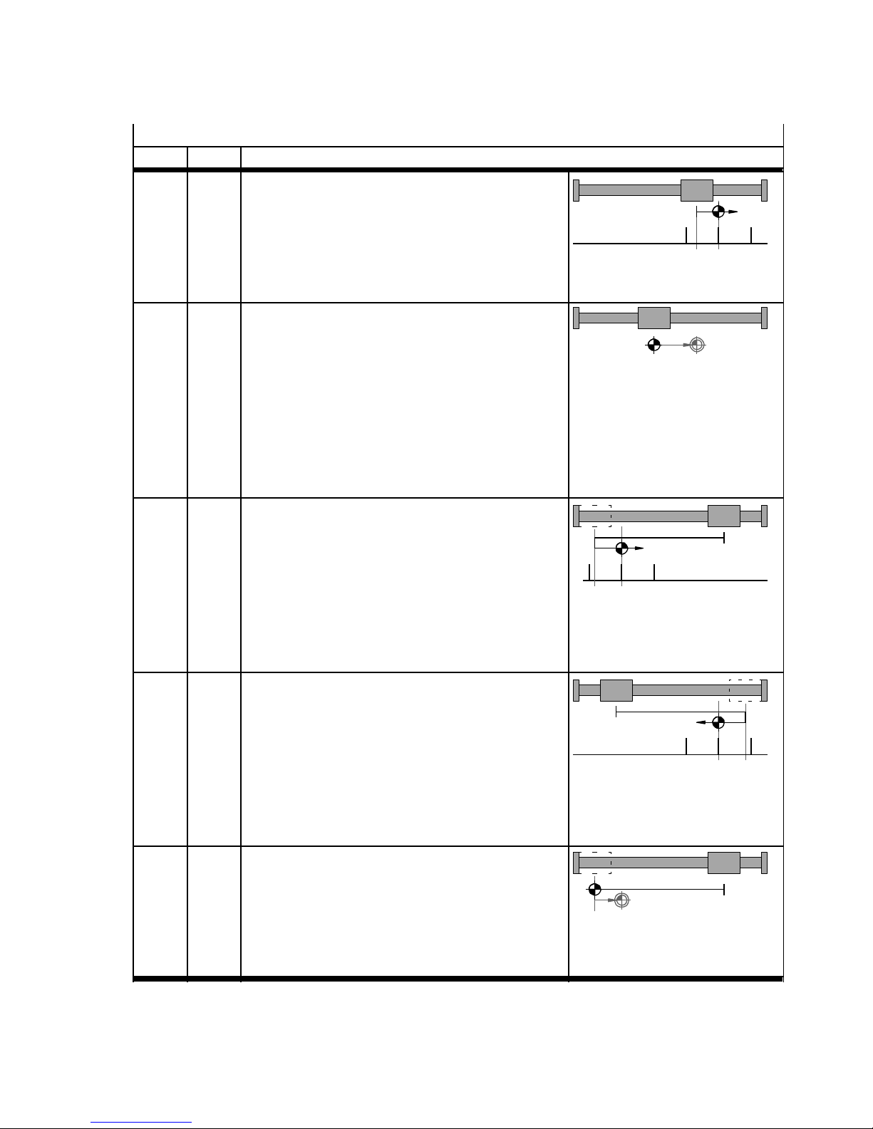
6Functions
Homing methods
hex Descriptiondec
22h 34 Index pulse in positive direction
1. Travel at creep speed in positive direction until
the index pulse. This position is taken as the
homing point.
2. If this is parameterised: travel at positioning
speed to the axis zero point.
23h 35 Cur rent position
1. The current position is taken as the reference
position.
2. If this is parameterised: travel at positioning
speed to the axis zero point.
Note: Through shifting of the reference system,
travel to the limit switch or fixed stop is possible.
For that reason this method is mostly used for
axes of rotation.
FFh -1 Negative stop with index pulse
1. Travel at search speed in negative direction to
the stop.
2. Travel at creep speed in positive direction until
the next index pulse. This position is taken as
the homing point.
3. If this is parameterised: travel at positioning
speed to the axis zero point.
FEh -2 Positive stop with index pulse
1. Travel at search speed in positive direction to
the stop.
2. Travel at creep speed in negative direction until the next index pulse. This position is taken
as the homing point.
3. If this is parameterised: travel at positioning
speed to the axis zero point.
EFh -17 Negative stop
1)2)3)
1. Travel at search speed in negative direction to
the stop. This position is taken as the homing
point.
2. If this is parameterised: travel at positioning
speed to the axis zero point.
1)
Index pulse
1)2)
Index pulse
1)2)
Index pulse
1) Only possible for motors with encoder/resolver with index pulse.
2) Limit switches are ignored during travel to the stop.
3) Since the axis is not to remain at the stop, the travel to the axis zero point must be parameterised and the axis zero point offset
mustbe≠0.
Festo – GDCP-CMMP-M3-FW-EN – 1203NH 33
Page 34
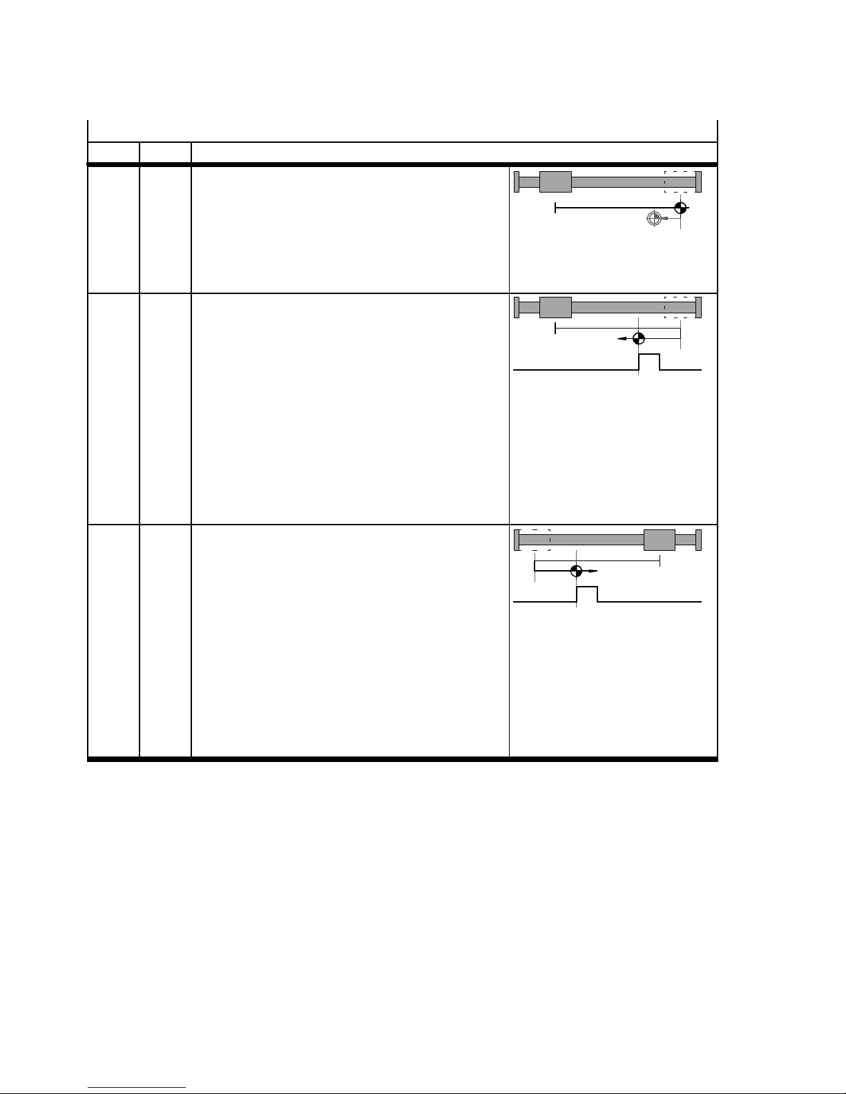
6Functions
Homing methods
hex Descriptiondec
EEh -18 Positive stop
1)2)3)
1. Travel at search speed in positive direction to
the stop. This position is taken as the homing
point.
2. If this is parameterised: travel at positioning
speed to the axis zero point.
E9h -23 Reference switch in positive direction with travel
to stop or limit switch.
1. Run at search speed in positive direction to
stop or limit switch.
2. Travel at search speed in negative direction to
the reference switch.
3. Travel at creep speed in negative direction until the homing switch becomes inactive. This
position is taken as the homing point.
4. If the axis zero point ≠ 0: Travel at positioning
speed to the axis zero point.
E5h -27 Reference switch in negative direction with
travel to stop or limit switch
1. Run at search speed in negative direction to
stop or limit switch.
2. Travel at search speed in positive direction to
the reference switch.
3. Run at crawl speed in positive direction until
reference switch becomes active. This position is taken as the homing point.
4. If this is parameterised: travel at positioning
speed to the axis zero point.
Homing Switch
Homing Switch
1) Only possible for motors with encoder/resolver with index pulse.
2) Limit switches are ignored during travel to the stop.
3) Since the axis is not to remain at the stop, the travel to the axis zero point must be parameterised and the axis zero point offset
mustbe≠0.
Tab. 6.7 Overview of homing methods
34 Festo – GDCP-CMMP-M3-FW-EN – 1203NH
Page 35

6Functions
6.2.2 Homing - options
Option
Travel to axis zero point after
homing
Homing with output stage and
controller enable
Function
After finding the reference point, the drive runs automatically to
the axis zero point.
Automatic execution of homing with a positive edge at the digital
input c ontroller enable if output stage and controller enable were
previously off.
For permanently referenced absolute value encoders, homing is
not restarted in I/O operation if it has taken place once and the
output stage enable has not been removed.
No homing after commutation Suppresses automatic homing after determination of the commut-
ation position.
This option is only effective for a drive without commutation signals (e.g. motor type ELGL). In the basis setting, homing is automatically started after successful definition of the c ommutation
position. This option must be marked to suppress this.
No synchronisation during
homing
No encoder emulation during
Suppresses switching off of the synchronised position during hom-
ing [X10].
During homing, no encoder signals are output at [X11].
Homing
Reference switch at index pulse
of [ X2B]
Evaluation of a reference pulse of the shaft encoder at [X2B] for
determination of the reference point. If this option is activated, an
index pulse from [X2B] is evaluated as a reference signal.
Timeout monitoring If the parameterised maximum time for homing is reached without
the homing point being found, homing is terminated with an error
message: “Time-out in homing”.
Limit se arch distance Path monitoring of homing: If the specified search distance
(e.g. effective stroke) is run without the homing point being found,
homing is terminated with an error message:
“Homing: End of search path reached”
Torque threshold Requirement: Homing method “Stop”
Optional specification of a torque for identification of the stop in
the homing method.
Tab. 6.8 Homing – options
Festo – GDCP-CMMP-M3-FW-EN – 1203NH 35
Page 36
6Functions
6.2.3 Homing parameters
The following parameters must be set for homing:
Parameter
Description
Speed The parameter setting applies for:
Acceleration/
deceleration
– Searching travel to the primary destination
– Crawl travel for identification of the switching point in the homing method
“Limit switch” or “reference switch”
Smoothing
– Travel to the axis zero point.
Axis zero point Definition of the axis zero point
Default values as a function of the set search direction
Linear axes ±3.00 mm (±0.100 in)
Axis of rotation ±10° (±0.030 R)
Tab. 6.9 Homing parameters
– Select the speed so that the reference mark can be detected by the controller. This
sometimes requires very low travel speeds.
– Set braking sufficiently high so that the motor c ontroller does not overrun the targets
too much during search travel.
6.2.4 Secur e zero point shift
Single-turn encoders that are set to permanently homed are already permanently homed on delivery.
The absolute zero point is stored by the manufacturer in the EEPROM of the encoder.
Note
Incorrect positioning of the axis.
Drives with absolute value encoders are always homed at switch-on to the absolute
encoder zero point stored in the encoder. For comparison between the homing point of
the c urrent measuring reference system and the mounting-related absolute zero point
of the motor encoder, the resulting offset in the EEPROM of the encoder must be stored.
The value is used for conversion of the actual position measured by the encoder.
• Carry out homing first
• Observe the subsequent special features for saving the zero offset.
Multi-turn
Absolute value e nc oders supply directly after switch-on an absolute position that is unique throughout
the entire travel distance of an axis. Such an encoder is calibrated on the measuring reference system
one time through homing and through a position offset stored in the EE PROM of the encoder (saving
the zero point offset).
36 Festo – GDCP-CMMP-M3-FW-EN – 1203NH
Page 37

6Functions
Single-turn
Single-turn encoders supply a unique position only within one motor revolution (partial-absolute encoder). At commissioning, the encoder is calibrated on the measuring reference system through homing and through zero point offset. Despite this, the absolute position is undefined after a RESET in most
cases (> 1 revolution), that is, homing is fundamentally required after each switch-on.
You can permanently home the drive for specific applications (e.g. for modulo positioning 0 … 1 R), so
that the status “referenced” is automatically set at switch-on. Homing at switch-on can then be optionally eliminated, as with the multi-turn encoder.
6.2.5 Homing via I/O
Homing via I/O can be started through the following methods.
A requirement in both cases is an act ive output stage and controller enable.
– Activation t hrough the assigned digital input “reference start”
– Selection of the positioning record 0 and activation of the assigned digital input “position selector -
start”.
Festo – GDCP-CMMP-M3-FW-EN – 1203NH 37
Page 38
6Functions
6.2.6 Timing diagrams
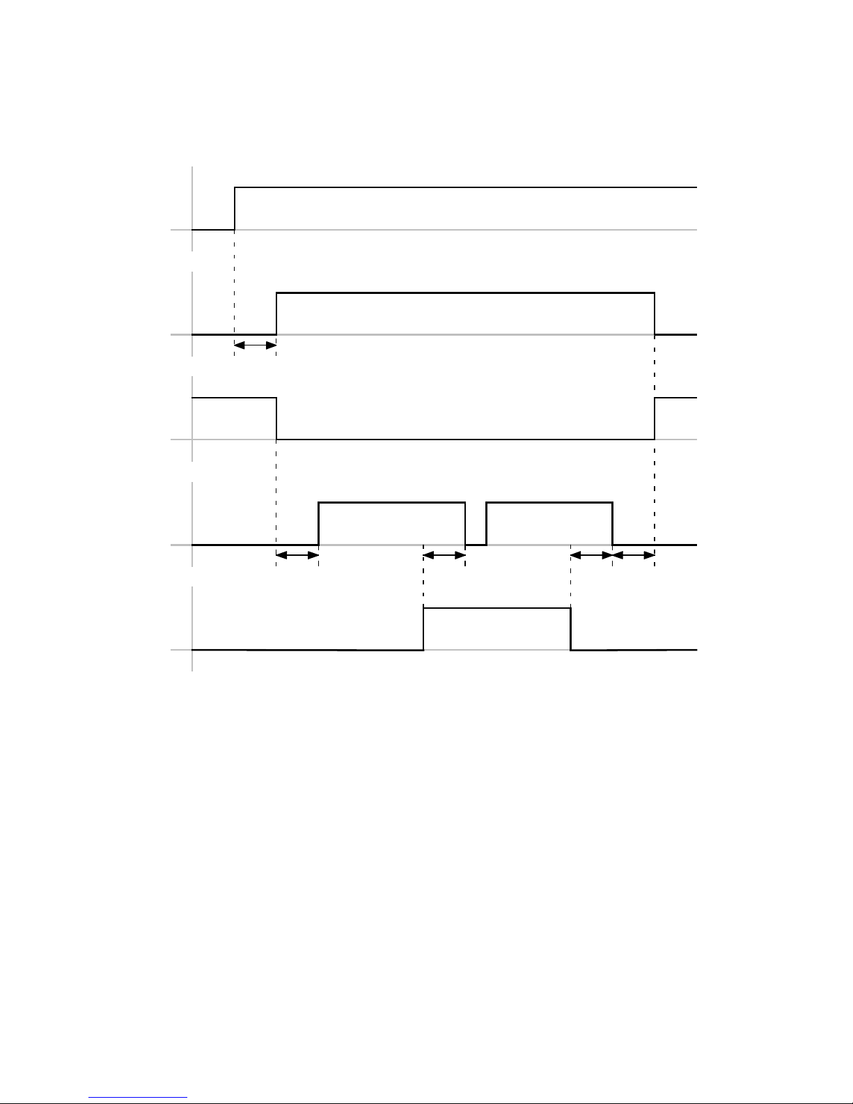
Start(DIN)
HA
1
MC
Speed <> 0
2
E0/E1
HA: HOMING_ACTIVE
MC: MOTION COMPLETE
E0: Limit switch 0
E1: Limit switch 1
Fig. 6.2 Timing diagram: homing without error
3 4 5
1 0…10ms
2 20 ms
3 Dependent on braking ramp
4 Dependent on braking ramp
5 20 ms
38 Festo – GDCP-CMMP-M3-FW-EN – 1203NH
Page 39
6Functions
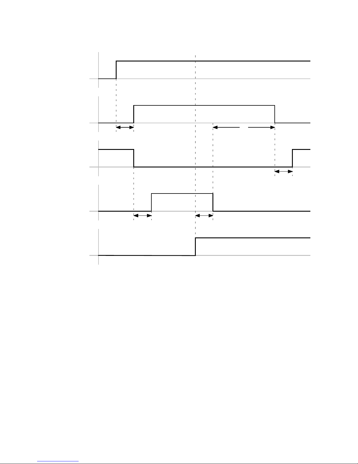
Start(DIN)
HA
MC
Error
4
1
5
Speed <> 0
2
ERR
HA: HOMING_ACTIVE
MC: MOTION COMPLETE
ERR: Error
Fig. 6.3 Timing diagram: homing with error
3
1 0…10ms
2 20 ms
3 Dependent on braking ramp
4 50 ms + x (x=delay until brake locked)
5 0…10ms
Festo – GDCP-CMMP-M3-FW-EN – 1203NH 39
Page 40
6Functions
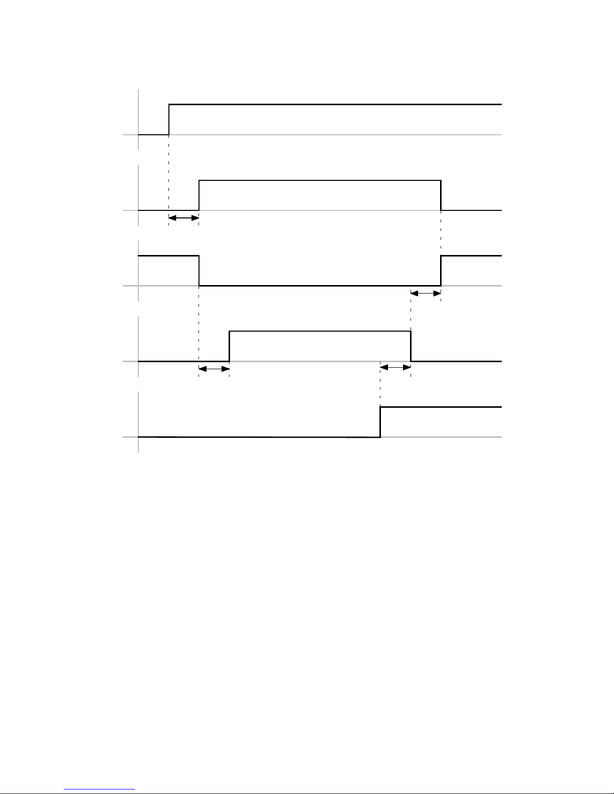
DIN8 (Start)
HA
MC
1
4
Speed <> 0
2
3
DIG. HOLD
HA: HOMING_ACTIVE
MC: MOTION COMPLETE
1 0…10ms
2 20 ms
3 Dependent on braking ramp
4 0…10ms
Fig. 6.4 Timing diagram: homing with digital halt
6.3 Jog mode
6.3.1 Function
In the “Operation enabled” status, the drive can be travelled through jogging in a positive or negative
direction.
This f unc tion is usually used for:
– Moving to teach positions
– Drive free running (e.g. after a system malfunction)
– Manual travel as a normal operating mode (manually operated feed).
The jog mode can be controlled as follows:
– Fieldbus/FHPP (jog mode)
– I/O interface through the parameterised digital inputs
40 Festo – GDCP-CMMP-M3-FW-EN – 1203NH
Page 41
6Functions
6.3.2 Process
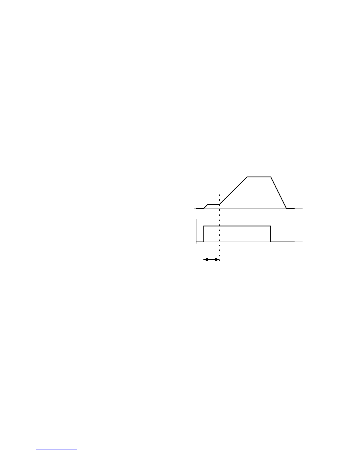
When one of the signals Jog positive/Jog negative is set, the drive star ts to move slowly. Due to the
slow speed (creep speed), a position can be defined very accurately.
If the signal remains set for longer than the configured “creeping period” the speed is increased until
the c onfigured maximum speed is reached. In this way large strokes can be traversed quickly.
If the signal changes to 0, the drive is braked with the pre-set maximum deceleration.
To protect the mechanics, smoothing can also be parameterised. All parameters can be set separately
for positive and negative travel direction.
If the drive is referenced:
The drive stops automatically if it reaches a software end position. The software end position is not
over-travelled; the path for stopping is taken into account according to the ramp set. The jog mode can
also only be exited here again after Jogging = 0.
1 Low speed phase 1
3
2
4
t(s)
(slow travel).
2 Maximum speed for
phase 2
3 Acceleration
4 Dec eleration
Speed
v(t)
1
5 Time period phase 1
(creeping duration)
Jog
positive/negative
1
0
5
Tab. 6.10 Sequence chart for jog mode
Festo – GDCP-CMMP-M3-FW-EN – 1203NH 41
Page 42

6Functions
6.3.3 Jog mode parameters
The following parameters must be set for jog mode:
Parameter
Function
Crawling speed Speed during the crawl period. Acceleration takes place with the ramp defined
under “Acceleration” and “Smoothing”.
Tab. 6.10 1
Slow moving time Durat ion of crawling - until th e shift to maximum speed.
Tab. 6.10 5
Max. speed Maximum speed during jog mode. Acceleration takes place with the ramp
defined under “Acceleration” and “Smoothing”.
Tab. 6.10 2
Acceleration Setpoint for acceleration of the drive during jog movements.
Tab. 6.10 3
Deceleration Setpoint for deceleration of the drive during jog movements.
Tab. 6.10 4
Smoothing Smoothing in acceleration value in % (default = 0 %).
– 0 % no smoothing
– 100 % jerk-free approach or jerk-free braking
Tab. 6.11 Parameters for jog mode
42 Festo – GDCP-CMMP-M3-FW-EN – 1203NH
Page 43
6Functions
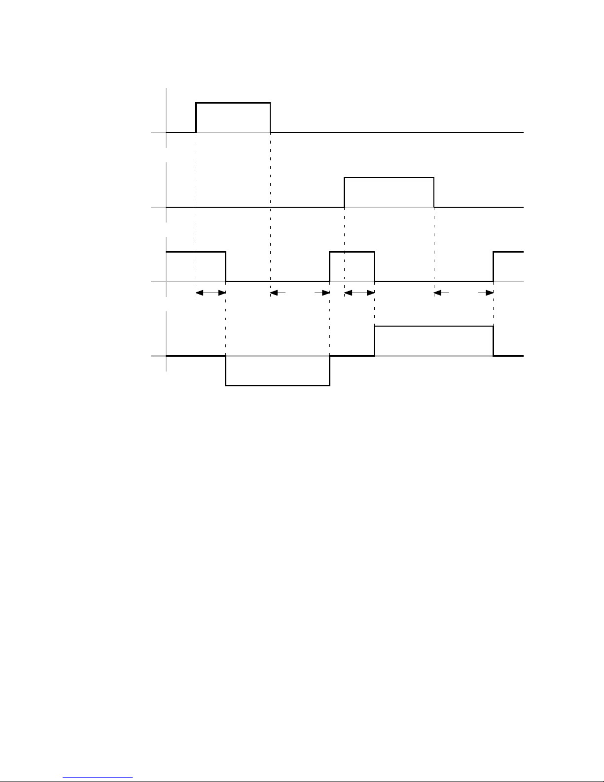
Negative
Positive
MC
2
1
1
Speed > 0
Speed < 0
MC: MOTION COMPLETE 1 0…10ms
2 Dependent on braking ramp
Fig. 6.5 Timing diagram. Jog positive/negative
2
Festo – GDCP-CMMP-M3-FW-EN – 1203NH 43
Page 44
6Functions
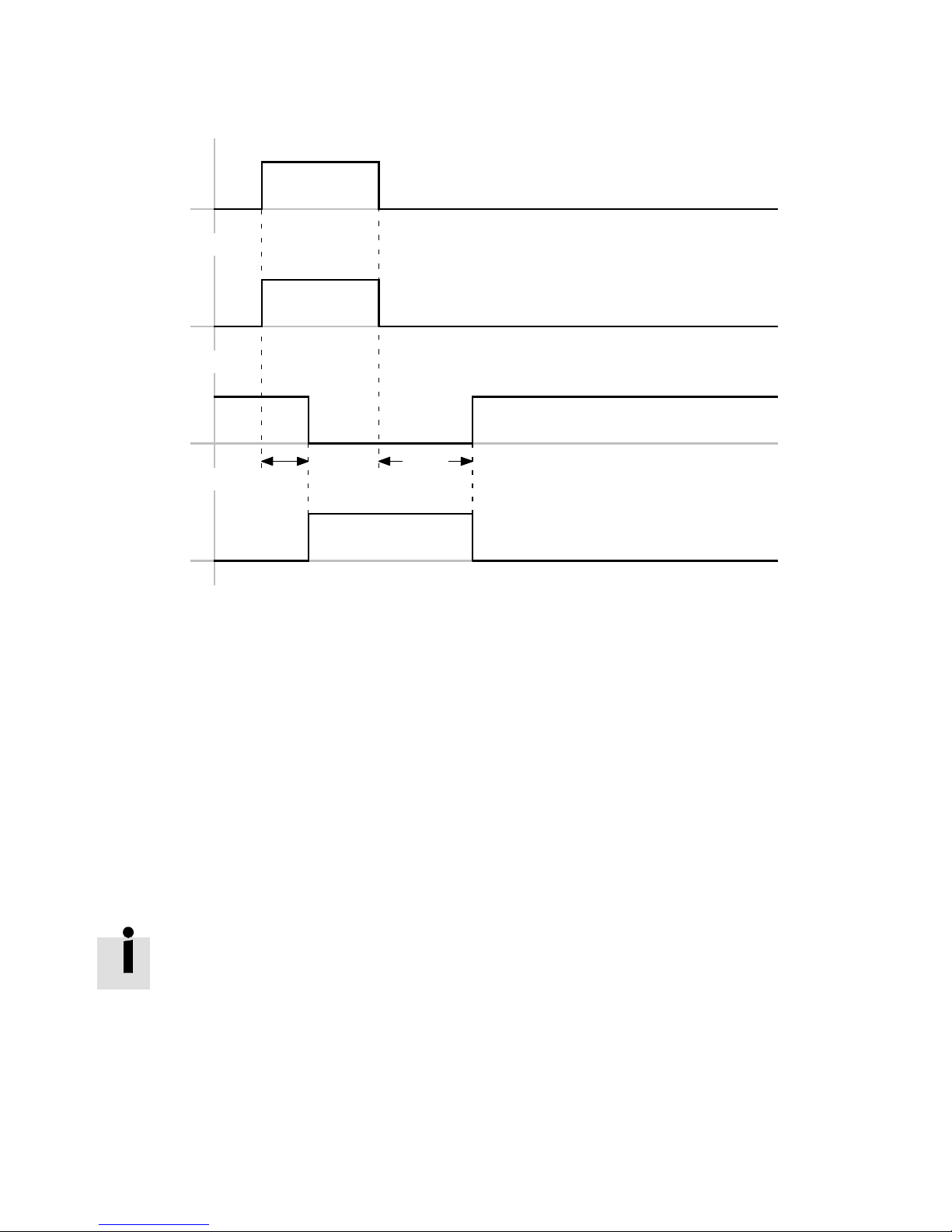
Negative
Positive
MC
1
2
Speed > 0
Speed < 0
MC: MOTION COMPLETE 1 0…10ms
2 Dependent on braking ramp
Fig. 6.6 Timing diagram: Jog positive/negative (simultaneously)
6.4 Teach-in function
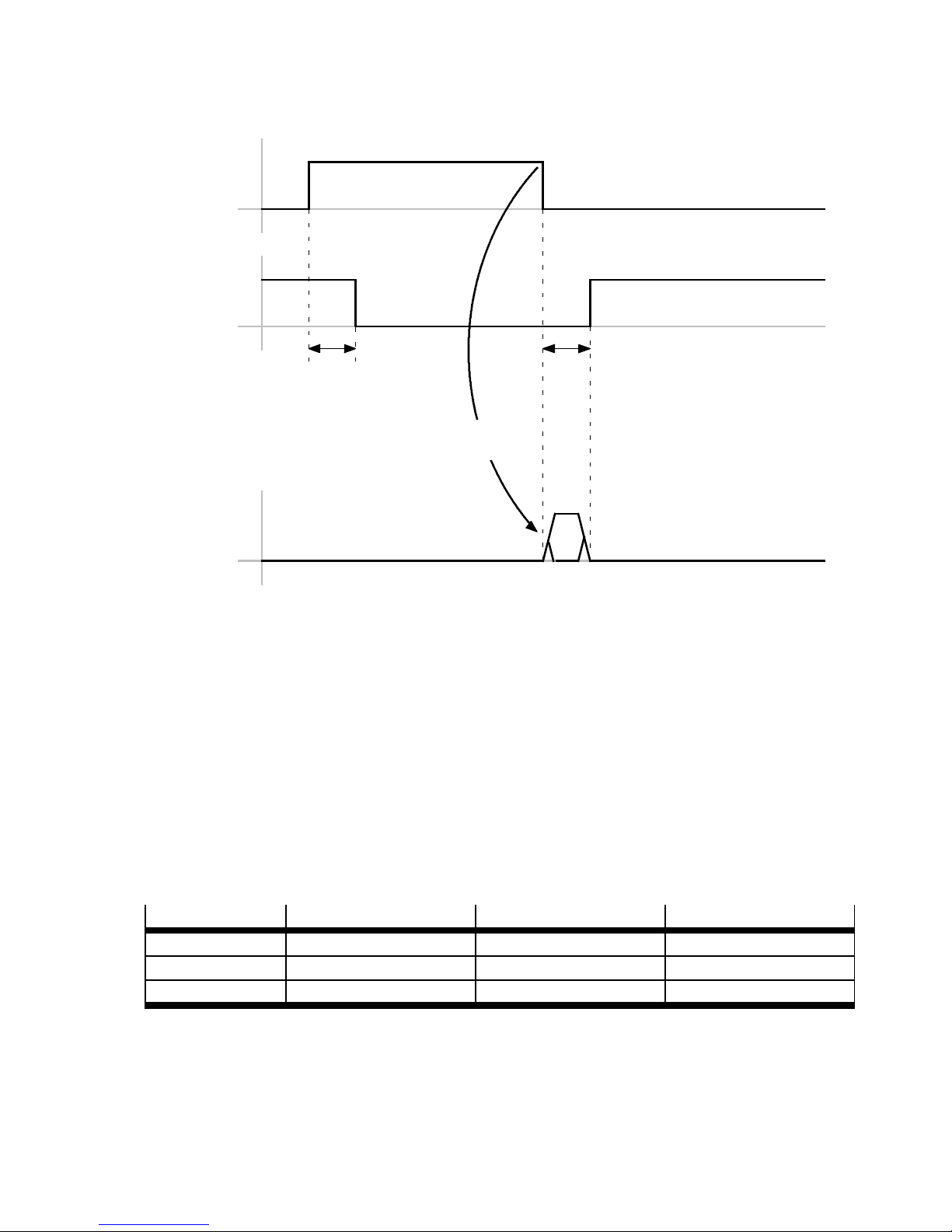
The teach procedure is started with the rising edge at the parameterised teach input. With the falling
edge, the actual position is temporarily stored in the position record selected via digital inputs.
To accept all temporarily saved position data, a positive edge at the parameterised “Save position”
input is required. The parameterised output “Saving process is running” goes to High at the start of the
saving process. Completion of the saving process is signaled through a Low signal at the “Saving process is running” output.
Data are temporarily stored in the volatile main memory of the controller and are immediately effective in the controller. These data are lost when the power supply is switched off
or in the event of a power failure. Data are stored permanently in the permanent memory
of the controller and remain available even after a power failure or switch-off.
44 Festo – GDCP-CMMP-M3-FW-EN – 1203NH
Page 45
6Functions
Teach (DIN)
TA
1
2
Digital position selector (bit
0…3,4…7optional)
Position saved
TA: TEACH_ACKNOWLEDGE 1 0…10ms
2 0…10ms
Fig. 6.7 Timing diagram: Teach
6.5 Setpoint specification
6.5.1 Analogue s etpoint
Through the analogue inputs, setpoint values can be specified as controller input data via a correspondingly scaled input signal.
The setting of the function is dependent on the number of inputs used, the selected control interface
and the selected operating mode/function.
Setpoint value
Torque/force x x x
Speed x x x
Position x – –
Tab. 6.12 Setpoint value via analogue inputs
Scaling
Specify in the FCT which value of the respective input variables corresponds to an input voltage of 10 V.
The scaled range c orresponds to a linear c haracteristic curve symmetric to the zero point
(e.g. –1000 R/min … +1000 R/min).
Festo – GDCP-CMMP-M3-FW-EN – 1203NH 45
AIN0 AIN1 AIN2
Page 46

6Functions
Zero balancing
With an externally specified voltage 0 volt, an undesired setpoint value can still be generated due to
voltage differences. For zero balancing, you can manually enter an offset in the FCT or execute synchronisation automatically (recommendation).
Through zero balancing, the scaled range is divided asymmetrically ( example Fig. 6.8: –750 …
+1250 R/min).
Safe Z ero
Threshold value of the input voltage, up to which the setpoint value = 0 is set to achieve a defined rest
of the drive, for example in the speed control mode, independently of offset fluctuations, noise, etc.
• Enter the threshold value U0 > 0 V an. If the input v oltage UIN is in the range +U0 … –U0, the setpoint v alue = 0 is output. The offset set for zero balancing is taken into consideration.
Note that specifying the threshold value means that an appropriate setpoint range is no
longer available for the application.
Filter time constant
AIN0 is a 16-bit input. Due to the high resolution, a digital filter is activated.
• Specify the time constant to be used to filter the input voltage.
46 Festo – GDCP-CMMP-M3-FW-EN – 1203NH
Page 47
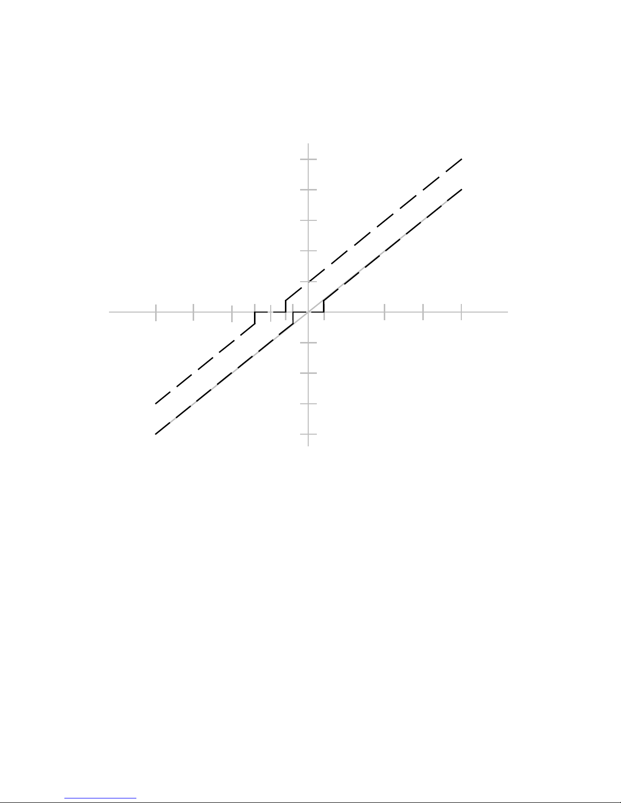
6Functions
1250
1000
2
500
1
-1
17.5510-10 -7.5 -5 -2.5
-500
-750
-1000
1 Safe Zero = 1 V 2 S afe zero = 1 V and Offset = 2.5 V
Fig. 6.8 Analogue setpoint value processing
6.5.2 Digital nominal value
Through the input [X10], the motor controller receives the signals of a transmitter, e.g. a second controller of type CMMx as synchronous setpoint value.
The interpretation of the setpoint value corresponds to the setting of the operating mode of the
CMMP-AS-...-M3. The switch takes place automatically in positioning mode, and through setpoint value
selector in the speed-controlled mode and force/torque mode.
Deactivate
Through a configured input (DIN) or FHPP, synchronisation can be switched on and off.
Festo – GDCP-CMMP-M3-FW-EN – 1203NH 47
Page 48

6Functions
Function Description
Position-synchronous operation with
speed pilot control
Signal at [X10] (= synchronous position) is taken over
directly as setpoint value (special case: control interface =
synchronisation) or added to the setpoint value
Applications:
– Flying saw
– CAM (cam disc)
Speed-synchronous operation with
torque limitation
Signal at [X10] = synchronous speed. Switch-on takes
place via setpoint selector:
Selector A <synchronous speed>
Selector B <torque limiting>
Force-/torque-controlled operation with
synchronous speed limiting
Signal at [X10] = speed limiting.
Switch-on takes place via setpoint selector:
Selector B <speed limiting>
Tab. 6.13 Synchronisation CMMP-slave (function)
Fundamentally, speed pilot control of the speed controller takes place in position-synchronous operation. The motor controller CMMP-AS-...-M3 can calculate the speed pilot control itself.
Position-synchronous with setpoint value addition
In the position-synchronous mode, the signal of the encoder interface [X10] is automatically added to
the setpoint value.
Position-synchronous without setpoint value addition
The synchronous value is taken over directly from the input [X10] as setpoint value. Setpoint value input
through record selection, direct mode or analogue input is blocked. No setpoint value addition takes
place.
Instructions on further position-synchronous applicatio ns with special settings can be
found in the subsequent chapters under:
– Flying saw ( chapter 6.5.4)
– CAM (cam disc) ( chapter 6.5.5)
In applications, it may occur that the sensor that gives the trigger signal (that is, registers the master
position which should be travelled to position-synchronously) lies outside the possible travel range of
the slave. The slave should then wait until the synchronous position of the master is in the travel range
of the slave. For this, the section between the sensor and the start of the travel path of the slave should
be known.
This is entered as position lead. The S tart can already exist before the travel range of the master position is reached. In this case, the drive does not start until positioning when the position lead has been
covered.
48 Festo – GDCP-CMMP-M3-FW-EN – 1203NH
Page 49

6Functions
Accidental positioning may occur here. If a start command is generated without a prior
trigger signal, the diagnostic event 41-0 is triggered:
(Record c ontinuation: Start of synchronisation without prior sampling pulse: Check
parameterisation of the pre-stop section)
Through the input SAMPLE, the current actual position of t he master system can be recorded (trigger
event). At each trigger event, the current master position of the input [X10] is saved.
After that, synchronisation can be started through the digital input START. A new synchronisation is not
initiated until a new start command, whereby the destination is calculated using the stored syn chronous position.
The advantage of this procedure is a more exact determination of the synchronisation destination,
since jitters at the start of synchronisation are reduced.
Speed-synchronous torque limitation
The setpoint speed is transferred to the slave by the master via the encoder interface [ X10] and added
as synchronous speed via setpoint selector A. You can optionally activate a torque limitation via selector B.
Synchronous speed limiting in torque-controlled operation
Torque-controlled operation with speed limitation via the encoder interface [X10]. The speed is transferred to the slave by the master via the encoder interface [X10] and activated as speed limitation via
setpoint selector B.
Required parameters
Parameter
Description
Electronic gear unit Through parameterisation of the gear ratios, exact translation
ratios between a master and slave drive are achievable. The default setting is 1 (number of lines of the slave : number of lines of
the master).
A transmission ra tio > 1 is a “reduction” r atio. The drive speed
(master) would therefore be bigger than the output speed (slave).
Speed filter Filter time c onstant of the synchronous speed
This describes the scanning rate (time slot pattern) used to refresh
the incoming signals at the synchronous input [X10].
Input tracks Depending on the encoder design, there are various signal inputs
available at [X10]. Alternatively, the following signals can be c onnected in accordance with RS422 specification:
– Differential inputs with TTL level A-B-(N),
– Differential inputs for SSI pulse/direction encoder (CLK/DIR) or
upward/downward counter (CW/CWW).
Festo – GDCP-CMMP-M3-FW-EN – 1203NH 49
Page 50

6Functions
Parameter Description
Number of lines The line c ount corresponds to the number of full periods in a track
per revolution. (Value must be between 1 and 2
28
). The incremental input always uses four-fold evaluation. Accordingly the resolution is higher than the line count itself by a factor of 4.
Tab. 6.14 Increment generator input parameter
The line count can normally be found in a data sheet or the name plate for the shaft encoder. Observe that specification of the line count is dependent on the track signals.
A/B-(N):
– A/B (quadrature evaluation): The line count of the master is entered with reference to
one revolution.
– Index track: If the index track is used, the specified line count must correspond to the
number of lines between index pulses.
CLK/DIR (pulse/direction):
– The number of increments for the master referred to 90° must be entered here due to
the c ontroller's four-fold evaluation method.
CW/CCW (upwa rd/downward counter):
– The number of increments for the master referred to 90° must be entered here due to
the c ontroller's four-fold evaluation method.
After a change of the encoder data, you must save the data following download and perform a restart with interruption of the power supply.
50 Festo – GDCP-CMMP-M3-FW-EN – 1203NH
Page 51

6Functions
Tracking sig-
1)
nals
A/B-(N)
Quadrature evaluation
Description Option
Standard incremental signals.
Two rectangular track signals whose
phases are offset by 90° are evaluated.
A defined pulse is output once per revolution (=zero index).
The zero index can be used for definition of a switching point, for counting
revolutions or for synchronisation of a
following counter.
CLK/DIR Pulse-direction interface.
The controller can also be controlled
from stepper motor controller cards
through these signal inputs.
CW/CCW Clockwise/counterclockwise counters
Two signals each separately supply the
change in position for a direction of rotation.
This means that when there is a pulse
train on one signal line, the other signal
line should be quiet.
– A/B track switch-off:
The incremental signals A/B are ignored (“encoders standing still”).
– Zero track switch-off (ignore zero
pulse):
The zero pulse generates a position
jump if necessary if individual incrementsoftheA/Btrackarenotcorrectly detected during operation.
If the index pulse results in malfunctions, the signal can be suppressed.
– Counting signals switch-off:
The signals CLK/DIR are ignored
(“encoders standing still”).
– Counting signals switch-off:
The signals CLK/CCW are ignored
(“encoders standing still”).
1) In accordance with RS 422 specification, specifications must be taken from the data sheet of the encoder.
Tab. 6.15 Track signals ( slave, input [X10])
6.5.3 Master-slave
The motor controller CMMP-AS-...-M3 permits a master-slave mode, which hereafter is designated
synchronisation. The motor controller can function both as master and as slave.
If the motor controller CMMP-AS-...-M3 operates as master, it can provide a slave with the current rotor
position at the incremental encoder output [ X11] .
If the motor controller CMMP-AS-...-M3 is to operate as a slave, the [X10] input is available for synchronisation. The motor controller CMMP-AS-...-M3 c an calculate the speed pre-control values itself. All
inputs c an be activated/deactivated. The internal encoder can be switched off if desired if another input
is used as the actual value encoder. This also applies in the speed adjustment operating mode.
The external inputs can be weighted with gear ratios. The various inputs can be used individually and
also simultaneously.
6.5.4 Flying s aw
“Flying saw” designates position-synchronous applications in which synchronisation is activated or
deactivated, dependent on the positioning record. The setpoint value at the synchronisation input is
added to the setpoint position value in the selected record only.
Festo – GDCP-CMMP-M3-FW-EN – 1203NH 51
Page 52

6Functions
Prerequisites
The following settings must be parameterised:
1. Control interface I/O or fieldbus
2. Selection of the following operating modes/functions
– Positioning mode
– Synchronisation ([X10]/slave)
– Flying saw
3. Set the parameters of the encoder interface [X10].
Function
– Synchronous positioning records for synchronisation with the rotation of the master
– Non-synchronous positioning records for travel to the rest position/wait position
– Upward and downward synchronisation so that not jerking movements are generated.
Activate
If the “Flying Saw” function is set, synchronisation can be activated or deactivated by starting c ommand records.
• Set synchronisation for the respective positioning record via the “Positioning record” dialog:
Synchronisation activated (Sync):
With synchronisation active, the current position of the master drive is switched onto the position setpoint value of the motor controller via the encoder at connection [ X10] . The drive thus follows the
changes in position of the master drive.
Synchronisation is activated when positioning is started, if it was not already. If the master is not stationary when positioning star ts, the offset that occurs will be made up in a controlled manner. The positioning speed used for this corresponds to t he speed of the master plus the positioning speed entered
in the positioning record as an excessive increase in speed. The entries of the started positioning record are likewise used for the accelerations.
Synchronisation deactivated (No Sync):
Synchronisation is deactivated when positioning is started, if it was not already. Positioning starts with
the current setpoint speed, that is, with the speed of the master. This results in controlled desynchronisation.
Synchronisation deactivated (Sync Out):
Synchronisation is deactivated when positioning is started, if it was not already. Positioning starts with
the c urrent synchronous positioning speed (rotational speed of the master). This results in controlled
desynchronisation.
Note
Observe the following:
When positioning with synchronisation is activated, the digital halt only stops the positioning record, but not necessarily the movement of the drive, since synchronisation
remains active!
Synchronisation must be explicitly terminated by starting a new positioning record
without synchronisation or by using the digital input “Disconnect sync.”.
52 Festo – GDCP-CMMP-M3-FW-EN – 1203NH
Page 53

6Functions
6.5.5 Scope of functions for cam discs (CAM)
The term “electro nic cam disc” designates applications in which an input angle or an input position is
depicted through a function as an angle setpoint value or a setpoint position. These applications are
typically master-slave applications.
The CMMP-AS-...-M3 has the option of processing 16 cam discs each with 4 assigned cam tracks. The
CMMP-AS-...-M3 provides the following functionality for this purpose via F HPP:
– Slave with synchronisation operation onto external input with cam disc
– Virtual master (internal) with cam disc.
A requirement is the positioning mode operating mode (record selection or direct mode). Additional
information on parameterisation can be found in the Help for the CMMP-AS plug-in. For complete in-
formation on the cam disc function, see the special cam disc manual P.BE-CMMP-CAM-SW-....
6.6 Second measuring system
6.6.1 Technology
Purpose
A second measuring system is used if the displacement measurement integrated into the motor is not
sufficient. There are 2 main reasons for this:
– double safety (for instance, at safely reduced speed)
Inclusion of a displacement encoder for secure applications is not described further here.
– The accuracy is not sufficient
For instance, if the resolution of the motor encoder is not sufficiently large. But more frequently, it is
the mechanics between the motor and positioned unit (for instance, slide of a toothed belt axis)
that is not precise enough.
Absolute positioning accuracy
Most frequently, a second displacement encoder is used to improve the absolute positioning accuracy.
Here, an absolute reference is used directly for the moving mass. The second measuring system corrects inaccuracies between the motor encoder and the moving mass.
The relative positioning accuracy results from the system of all components (motor, gear unit, coupling,
axis,…) and is used, for example, when teaching positions. For most applications, a high relative positioning accuracy, also called repetition accuracy, is sufficient.
Since a second displacement encoder means expense, both mechanically and in parameterisation, the
accuracies of common systems are compared in the following:
Festo – GDCP-CMMP-M3-FW-EN – 1203NH 53
Page 54

6Functions
6.6.2 Example, toothed belt axis
Component
Type
Motor EMMS-AS-70-M-Rx
Gear unit EMGA-60-P-G3-SAS-70
Axis EGC-80-2000-TB-KF-0H-GK (real feed constant 90.2 mm/R)
Tab. 6.16 Toothed belt axis components
Parameterisation
Repetition accuracy Approx. absolute accuracy
Standard parameterisation [mm] 0.08 4.44
Parameters with real feed
[mm] 0.08 0.44
constant
External displacement encoder [mm] < 0.08
1) Depending on the system used (possible loose gears or gear backlash are compensated with the 2nd measuring system and thus
improve the absolute accuracy.)
1)
< 0.10
1)
Tab. 6.17 Repetition accuracy of toothed belt axis
6.6.3 Example, spindle axis
Component
Type
Motor EMMS-AS-70-M-Rx
Axis EGC-80-2000-BS10-KF-0H-Mx-GK-S (Feed constant = 10 mm/R)
Tab. 6.18 Spindle axis components
Parameterisation
Repetition accuracy Approx. absolute accuracy
Standard parameterisation [mm] 0.02 0.05
External displacement encoder [mm] < 0.02 < 0.05
Tab. 6.19 Repetition accuracy of spindle axis
6.6.4 Function in the controller
In the controller, the position actual value of the external displacement encoder is evaluated instead of
that of the motor encoder. Both commutation and speed adjustment continue to be made through the
encoder in the motor.
Through encoder difference monitoring, an adjustable offset between the motor encoder and external
measuring system is detected and reported. Errors, for instance mechanical offset, failure of external
encoders or torn toothed belt, result in stopping with a corresponding error message.
54 Festo – GDCP-CMMP-M3-FW-EN – 1203NH
Page 55
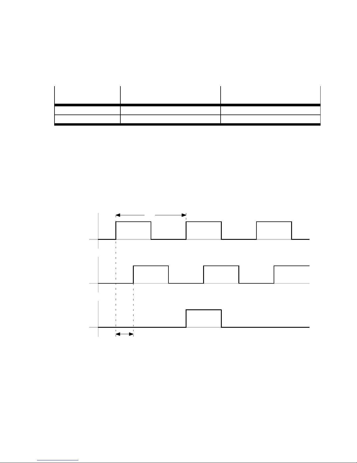
6Functions
6.6.5 Inclusion of a second displacement encoder
At the CMMP-AS-...-M3, position actual values can be read in through 3 interfaces. Observe here that
the motor encoder already occupies one interface:
Motor with encoder
Used interface Free interfaces
type
Encoder [X2B] [X2A], [X10]
Resolver [X2A] [X2B], [X10]
Tab. 6.20 Interface assignments
The second displacement encoder must first be parameterised in the FCT software, independently of
the motor and encoder type.
6.6.6 2nd measuring system at the incremental encoder input [X10]
The incremental encoder input [X10] can be used both for motors with encoder and for motors with
resolver. After switch-on (24V voltage off or reset), homing must be executed first.
The interface [X10] supports all commonly available incremental encoders with 5 volt level.
The A/B tracks are thereby evaluated fourfold through edge detection.
4
1
2
3
5
1 Tr a ck A
2 Tr a ck B
4 Increment distance/signal period
5 Resolution through fourfold evaluation
3 Zero track
Fig. 6.9 Timing diagram: evaluation of incremental encoder
Alternatively, pulse-direction signals or upward-downward counters can be evaluated at [X10], likewise
with 5 volt level.
Festo – GDCP-CMMP-M3-FW-EN – 1203NH 55
Page 56

6Functions
For the cable, a screened line that twists together the data pairs A and A#, B and B#, N
and N# (twisted pairs) must be used. The outer screening must always be connected on
both sides, at the controller to the plug housing. Only with the recommended line can
reliable transmission with higher frequencies be ensured.
The 2nd displacement encoder must be activated in the FCT. In parameterisation, differentiation is
made between linear and rotative incremental encoders.
With linear measuring systems, the signal period, that is, the increme nt distance, is entered.
The real line count for rotative encoders or the real resolution ( signal period) for linear encoders
must be parameterised; this corresponds to the value before the quadrature evaluation.
For linear systems, in addition to the signal period, the reference signal (distance between two adjacent
zero-pulse signals) must be parameterised.
Through the selection of reversal of direction, the counting direction of the 2nd displacement encoder
can be turned. With activated encoder difference monitoring, the permissible encoder difference is
specified in °.
The error E 171 (deviation between position actual value and commutation encoder too large) is output
if the actual position of the motor deviates by x° from the actual position of the external displacement
encoder. In particular for toothed belt axes, the value must not be selected too small, since an offset
always occurs due to expansion of the toothed belt under load.
In the case of rotative incremental encoders, it is not the signal period, but the line count per revolution
of the external encoder that is specified. In addition, a transmission ratio (standard 1:1) can be configured. The line count always refers to one revolution of the motor.
With the values to be entered here for an “electronic gear unit”, the transmission ratio between the
commutation encoder (in the motor) and the 2nd encoder as position encoder is compensated for.
Enter here the inverse of the multiplicative product of the gear unit present between the two encoders.
All o ther parameters must be set as with the linear system.
6.6.7 EGC-...-M at [X10]
For EGC axes with type code –M, an incremental displacement encoder is already attached.
The sensor of the 2nd displacement encoder of an EGC-…-M axis has the following technical data:
Axis
Signal period Reference signal
EGC-...-M1 [mm] 0.01 5
EGC-...-M2 [mm] 0.04 5
Tab. 6.21 Signal period EGC
As par t of the normal parameterisation, the 2nd displacement encoder must be activated.
Through the selection of reversal of direction, the counting direction of the 2nd displacement encoder
can be turned.
Parameters to be set:
– Signal period ( Tab. 6.21)
– Encoder difference
– Reference signal
56 Festo – GDCP-CMMP-M3-FW-EN – 1203NH
Page 57

6Functions
The encoder difference of 60° represents a start value that is operational in most cases. But it must be
adjusted, depending on the application.
6.6.8 2nd measuring system at input [X2 A]
The input [ X2A] can only be used for motors with encoder. After switch-on (24 V voltage off or reset),
homing must be executed first.
The interface [X2A] supports all commonly available incremental resolvers, single-pole or multipolar.
6.6.9 Commissioning
After parameterisation, the system is commissioned.
Before the first enable, the counting direction of the motor and of the external encoder must be
checked.
To do this, shift the moving mass by hand and observe the change in the FCT (online area – operate).
The actual position is recorded by the external encoder, and the speed is calculated from the encoder in
the motor. Both values change as a result of shifting by hand. The direction of the system c an be selected freely and is usually simply selected corresponding to the application. After selection of a suitable
zero point, shift the axis by hand in a positive direction. If the actual position becomes smaller rather
than larger, the direction of the 2nd measuring system must be changed. If the speed is negative, the
direction of rotation of the motor must be reversed.
After each change, download, save and restar t must be done.
For motors with integrated brake, the brake can be manually opened with the button R elease brake.
Note
For vertical axes, the moving masses must be secured against falling.
After that, the c ustomary commissioning is c ontinued.
Usually, the controller data must be adjusted manually to achieve a good positioning. For longer
toothed belt axes, reinforcement of the position controller must not be too large, since the system
would otherwise swing up.
Festo – GDCP-CMMP-M3-FW-EN – 1203NH 57
Page 58
6Functions
6.7 Additional functions
6.7.1 Encoder emulation
The output [X11] of the motor controller can simulate an encoder that can be used by another device as
an input signal.
The output [X11] is active even if the function has not been activated in the FCT.
In the FCT, the following configurations can be made.
Option
Description
Encoder Data
Number of lines Number or lines (increments) per revolution.
Track A and track B are offset by 90°. As a result, the connected incremental input can increase the resolution with a fourfold evaluation. The
result is, the number of increments per revolution is increased by the
factor 4.
Offset Angle Additive c orrection value in the range from -180° to +180° for
electronic adjustment of the zero position.
Options
Disable track A,B The incremental signals are n ot output (“encoders standing still”).
Suppress zero pulse The emulated incremental encoder does not output a zero pulse.
Inverse rotation polarity The phase position of tracks A and B is rotated by 180° (right rotation
field -> left rotation field)
Encoder output
Position virtual master Only for activated cam disc function with virtual master.
Actual position – With cam disc function: actual value of slave position.
– Without cam disc function: actual position of the motor controller.
Setpoint value position – With cam disc function: setpoint position of the slave.
– Without cam disc function: setpoint position of the motor
controller.
Tab. 6.22 Configuration of the encoder emulation
58 Festo – GDCP-CMMP-M3-FW-EN – 1203NH
Page 59

6Functions
6.7.2 Brake control and automatic brake
Function
The motor controller CMMP-AS-...-M3 can directly control a 24V holding brake integrated into the motor
Caution
If the maximum permissible connected loads are not complied with:
– The controller can be destroyed
– The functioning of the holding brake is not reliable.
• For correct connection and reliable control of the brake (safe stop, emergency stop),
observe the instructions in the hardware description
• In th e case of h igher current needs, the brake must be switched via a coupling relay,
if necessary with interference suppression.
Note
The holding brake must not be used to brake moving masses. Braking masses in movement leads to increased wear and the functional failure of the holding brake:
– The brake must be opened before a new positioning motion begins.
– The drive must stand still before the brake is closed.
• Pay attention to the required time delays (brake delay time), in particular for holding
brakes with high mechanical inertia.
With lo nger time delays between command records, the automatic function of the holding brake closes
the brake and switches off the controller output stage (less temperature rise).
Note
In cer tain applications (e.g in synchronous mode), the automatic function can damage
the brake and/or the system.
In the case of parameterisation via the FCT software, the automatic brake can therefore
not be activated for synchronous operation.
• Check the operating conditions in your application before you activate the automatic
brake.
If no command record is executed in the specified time, for axes under load:
– The current setpoint value is set to zero
– The brake is engaged
– The controller end stage is switched off.
Example
In this example, the activation time of the automatic brake starts to run after the completion of a positioning record (MC). After the activation time has expired, the brake is closed and the switch-off delay
runs simultaneously. After the switch-off delay has expired, the controller end stage is switched off
(less warming).
Festo – GDCP-CMMP-M3-FW-EN – 1203NH 59
Page 60
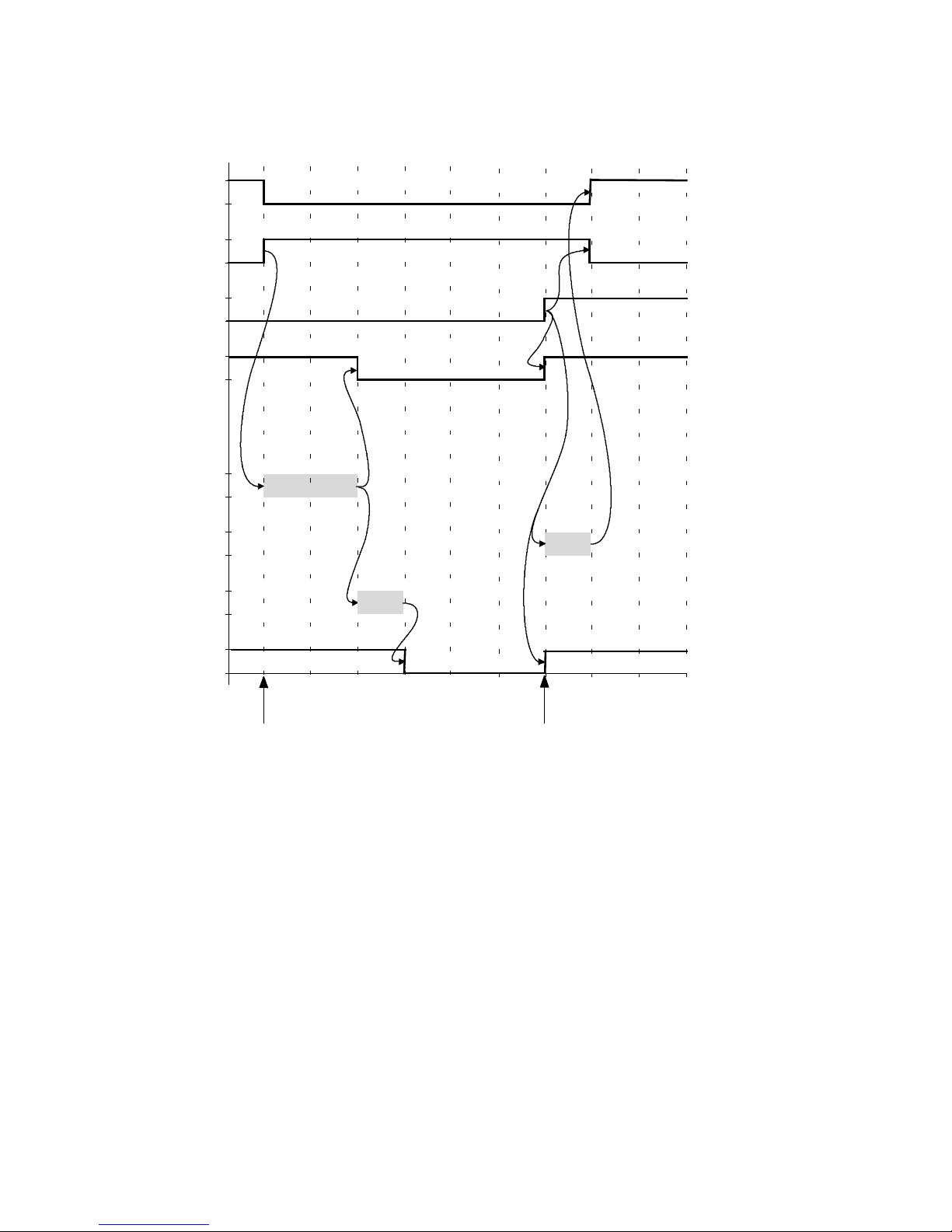
6Functions
After the start of a new positioning record, the drive moves only after the switch-on delay has expired.
Drive
is mov ing
MC
START
Open
brake
Automatic
Switch-on
delay
Switch-off
delay
1
0
1
0
1
0
1
0
1
0
1
0
1
0
Controller
energised
1
0
Record
completed
Start of new
positioning record
Fig. 6.10 Pulse-time diagram - holding brake with automatic function
60 Festo – GDCP-CMMP-M3-FW-EN – 1203NH
Page 61

6Functions
Parameters
Parameter
Function
Switch-on delay Requiredtimetocompleteopeningofthebrakewith:
– Setting of the controller enable (DIN5 0
}
1)
– START signal (if the automatic brake is activated) and the start
of a positioning motion.
The configured brake output is set immediat ely; the brake opens.
Correct setting ensures that the drive does not run against the
closed brake. With a STA RT signal before the switch-on delay
expires, the motor controller starts the positioning motion only
after the switch-on delay has expired completely.
Switch-off delay Required time until complete closing of the brake with:
– Removal of controller enable (DIN5 1
}
0)
– Expiration of the activation time of the automatic brake.
Correct setting ensures that the drive is maintained in the current
position until the holding brake has achieved its full holding
torque. The controller is only switched off after the switch-off delay
has expired.
Activation time of the automatic
brake
Time in [ms] between the completion of a positioning motion
(“Motion complete”) and the resetting of the brake output
(providing in this period of time there is no new START signal). The
switch-off delay follows after the activation time.
Value = 0 deactivates the automatic brake.
Tab. 6.23 Parameter safe brake control
6.7.3 Position trigger
The position triggers can be used to pass on information about the logical statuses of position
switches, rotor position switches and cam controller units (only when the cam disc function is activated) to digital outputs. Four position triggers can be configured to this end.
With specified trigger levels, the position triggers can:
– implement the actual position of the commutation encoder corresponding to the value pair (switch)
in binary signals (1/0)
– output the binary signals logically linked with OR to the assigned digital outputs.
A maximum of four value pairs for positions or four value pairs for rotor locations must be assigned to
each position trigger. To depict the information on a digital output, the function of a digital output must
be set to “position trigger 1” … “4”.
Festo – GDCP-CMMP-M3-FW-EN – 1203NH 61
Page 62
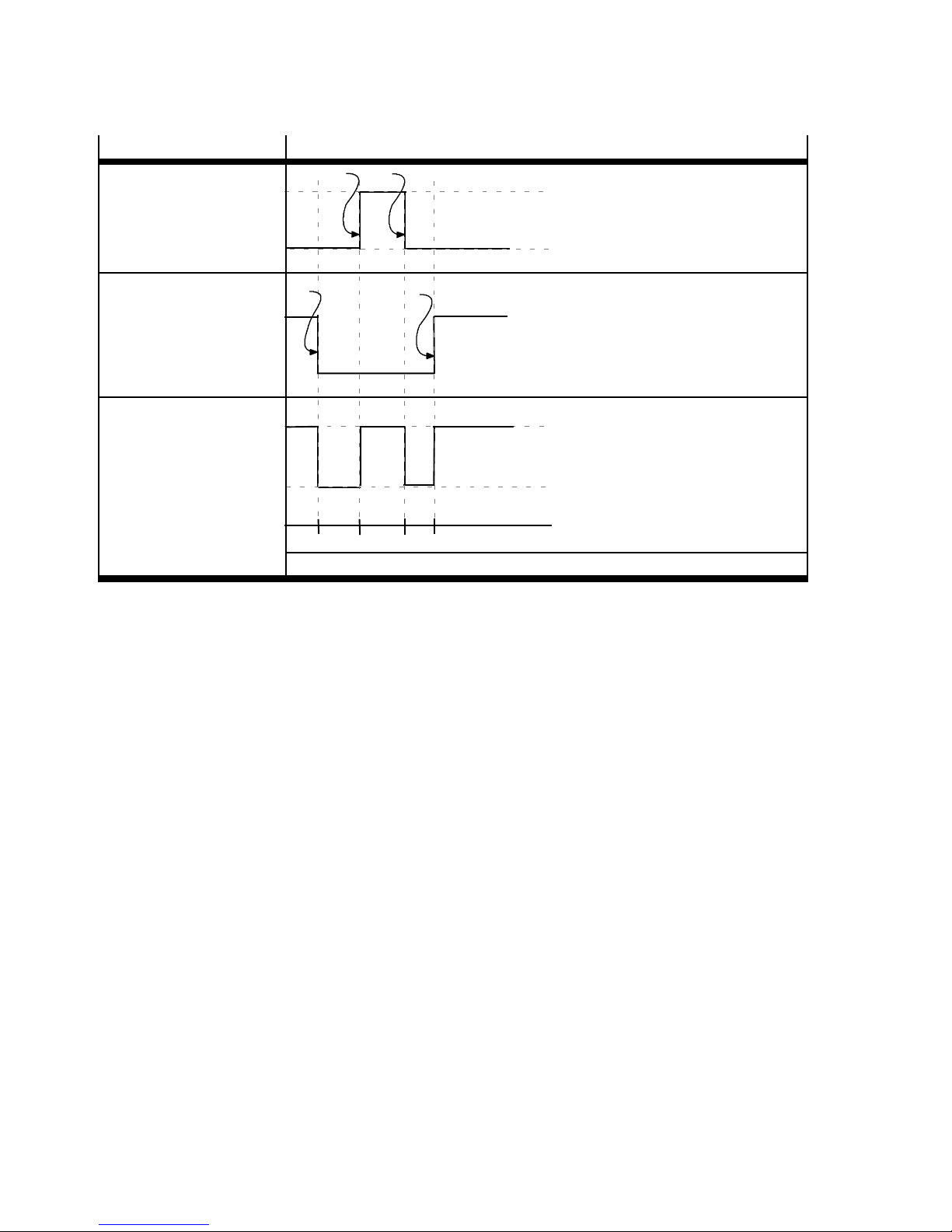
6Functions
2
Example Position trigger
Trigger signal switch 1:
– Position 1 = 400 mm
– Position 2 = 700 mm
Trigger signal switch 2:
– Position 1 = 100 mm
– Position 2 = 900 mm
– Signal inverted
Position trigger 1/DOUT:
– Logical OR operation
of the trigger signals
Tab. 6.24 Position trigger
3
1
2
1
100 400 700 900
3
4
4
1
0
1
0
1
0
6.7.4 Inputs for option “flying measurement”
The local digital inputs can be used as quick sampling inputs. Setting of the digital input takes place in
the FCT. The inputs DIN8 or DIN9 can be selected.
With every rising and falling edge at the configured sample input, the current position value is written
into a register of the controller and can afterwards be read out through the higher-order controller
(PLC/IPC). Additional information on the available parameters can be found in the documentation for
FHPP (GDCP-CMMP-M3-C-HP-...) or CANopen (GDCP-CMMP-M3-C-CO-...).
6.7.5 Software limit switch
The permissible positioning range (effective stroke) is limited by setting the software end positions.
The software end positions refer to the axis zero point. If the target position of a positioning command
lies outside of the software limits, the positioning command will not be processed and an error status
will be set.
62 Festo – GDCP-CMMP-M3-FW-EN – 1203NH
Page 63
6Functions
6.7.6 Input for digital halt
The control port “Digital halt” is high active (default). It immediately stops all movements. Other star t
signals do not work as long as this input is active.
The following delay ramp is run, dependent on the active operating mode:
Operating mode
Deceleration ramp
Positioning mode Ramp of the positioning record
Speed regulation Set speed ramp
Torque regulation Set torque ramp
Tab. 6.25 Delay ramp dependent on the operating mode
All available digital inputs can be assigned. After a “Halt”, there must always be a “Start”.
The polarity of the input can be switched via FCT.
Note
Note the following when using the “Flying Saw” function in combination with “Digital
I/O” as the control interface:
– When positioning with synchronisation is activated, the digital halt only stops the
positioning record, but not necessarily the movement of the drive, since synchronisation remains active!
– Synchronisation must be explicitly terminated by starting a new positioning record
without synchronisation or by using the digital input “Disable sync”.
6.7.7 I/O [X1]
Standard assignment and extension of the digital I/Os
The motor controller CMMP-AS-...-M3 has standard 10 digital inputs (DI N0 … DIN9) and 4 digital outputs (DOUT0 … 3). The existing digital inputs DIN0 … 9 are already assigned for typical applications
through basic logic functions:
– The inputs DIN0 … DIN3 are pre-assigned for selection of the positioning records (position selector)
and the inputs DIN8 and DIN9 for start and sample functions.
The factory setting can be changed, if needed, to correspond to the application.
– Fixed functions are assigned to the inputs DIN4 … D IN7 and the output DOUT0. This assignment is
not configurable.
The following I/O expansions are possible:
– Four additional inputs (DIN10 … 13) are possible through corresponding reconfiguration of digital
outputs or analogue inputs with FCT
– Two extension modules, each with 8 additional digital inputs and out puts (accessories type
CAMC-D-8E8A).
Festo – GDCP-CMMP-M3-FW-EN – 1203NH 63
Page 64
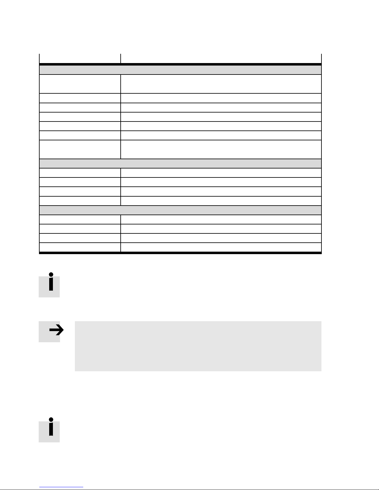
6Functions
Digital I/O Function
Standard DIN
DIN0 … DIN3 Position selector, selection of the positioning records (0 … 15)
configurable
DIN 4 Fix: Output stage enable (POWER ENABLE)
DIN 5 Fix: Controller enable (CONTROLLER E NABLE)
DIN 6 Fix: Limit switch negative (LIMIT 0)
DIN 7 Fix: Limit switch positive (LIMIT 1)
DIN 8 Configurable
DIN 9 Configurable high-speed input
(Sample input/reference switch)
Standard DOUT
DOUT0 Fix: Controller operational (READY)
DOUT1 Configurable
DOUT2 Configurable (optional: DIN10)
DOUT3 Configurable (optional: DIN11)
Additional DIN
DIN10 (DOUT2) Configurable
DIN11 (DOUT3) Configurable
DIN12 (AIN1) Configurable – trigger level at 8 V
DIN13 (AIN2) Configurable – trigger level at 8 V
Tab. 6.26 Assignment DIN/DOUT
Activated signal inputs require calculation time of the motor controller.
Therefore, do not deactivate required signal inputs.
Functions of the digital inputs
Note
Multiple assignments of digital in puts are tolerated by the firmware.
Execution of the function with multiple assignment depends on the respectively set
operating mode.
• Check carefully whether your combination of input signals makes sense.
Function assignment is dependent on:
– the control interface used
– the selected operating mode
– the number of freely usable inputs.
To control additional functions via digital inputs, you can change the factory-set
assignment of the digital inputs present at the basic unit.
64 Festo – GDCP-CMMP-M3-FW-EN – 1203NH
Page 65

6Functions
Function Description Polarity
General
Detecting the actual
position
(sampling)
Setup mode By setting the input, the maximum speed is limited dir-
The current actual position is saved in the internal
memory with rising or falling flank of the input in order to
transfer it to an external controller over fieldbus (see also
“Flying measurement”).
Positive
and
negative
edge
Low active
ectly to the setup speed set.
Release brake Input for releasing the holding brake with deactivated
High active
controller enable.
Switch off synchronisation With this, a previously activated synchronisation (e.g.:
Low active
Flying saw) must be switched off.
Synchronisation is switched off with a falling edge at the
parameterised input.
Record selection/positioning
Record selection
(position selector)
Selection of the positioning records 1 … 255
Selection of the reference travel (positioning record 0)
High active
The signals must be securely applied if the START edge is
set.
Start record After setting the START signal, the number of the active
High active
positioning record is taken over and the drive carries out
the record.
Digital halt In positioning mode, the drive brakes with the ramp of
the active positioning record.
After that, the drive is controlled (brake is opened).
Can be
paramet-
erised
Homing
Homing Switch Input that supplies the reference signal. Can be
paramet-
erised
Start homing After setting the START signal (0}1), the drive carries
High active
out homing. After completion of homing, positioning procedures can be carried out.
Jog mode
Negative travel direction Jog mode enables manual travel of the drive. In the “Op-
Positive t ravel direction High active
eration enabled” status, the drive can be travelled over
the positive/negative inputs.
High active
Festo – GDCP-CMMP-M3-FW-EN – 1203NH 65
Page 66

6Functions
Function PolarityDescription
Teach/save position
Teach position Theteachprocedureisstartedwiththerisingedgeatthe
parameterised teach input. With the falling edge, the
Start teach
high active
actual position is temporarily stored in the position record selected via digital in puts.
Tar ge t
transfer
low active
Save position To permanently accept all temporarily saved position
High active
data, a positive edge at the parameterised “Save position” input is required.
Start/stop record sequence
Run to HOME position The input starts the positioning record “HOME-Position”. High active
Run to the Star t position The input starts the positioning record “START position”. High active
Stop If the digital input is activated, the path program is
Low active
stopped. The ongoing positioning is still ended in any
case. In the position records, it can still be specified
whether the path program may or may not be stopped at
the end of this record. In this case, despite setting of the
Stop input, the subsequent chained positioning is started.
Combined star t/stop Through this function, starting and stopping of a path
program can be controlled through a unique digital input.
Start
high active
The general S TART position of the path program is
thereby approached on the rising edge of the digital input. On the falling edge, the already described Stop func-
Stop
low active
tion of the path program is activated.
Sequence control
Digital input NEXT1 Subsequent positions of a positioning record for record
High active
continuation through positioning record number and digital inputs. Execution (travel to the subsequent position)
corresponds to the logic operation of the digital inputs
Digital input NEXT2 High active
NEXT1 and NEXT2 through step enabling condition of the
positioning record. The digital inputs NEX T1 and NEXT2
are evaluated only through the step enabling conditions
GoImm, IgnUTP, GoATP.
Tab. 6.27 Function overview of the digital inputs
66 Festo – GDCP-CMMP-M3-FW-EN – 1203NH
Page 67

6Functions
Function of the digital outputs
The function can be determined for the available outputs DOUT1, DOUT2 and DOUT3 as follows:
Function
Description Polarity
Off The output is always low. –
On The output is always high. –
Group “Enabled”
Brake vented The output is active as soon as the brake is released. High active
Output stage active The output is active if the output stage enable has been
High active
granted (power enable present, motor energised).
Setpoint lock active The output is active as soon as one or both setpoint locks
High active
is triggered by a limit switch.
Linear motor identified This output is active if the commutation position has
High active
been found. For angle encoders without c ommutation
signals, the commutation position is determined by
means of an automatic function. Starting a positioning
movement, for example, only makes sense once this process is complete.
Reference position v alid The output is active if the drive is homed. High active
Collective status
Ready for controller enable
Output stage release level Returns the level of the output stage enable digital input
Signals the status that no error is present and the controller is ready for controller enable.
High active
High active
DIN4. The condition is fulfilled if the level at DIN4 =
HIGH.
Group “Movement”
Position Xsetpoint = Xdest The setpoint position is within the tolerance window of
High active
the target position.
Position Xact = Xdest The actual position is within the tolerance window of the
High active
target position.
Remaining Distance The output is ac tive if the deviation between the target
High active
and actual position has fallen below the set value for the
remaining distance message.
Reference run active The output is active as long as homing is active. High active
Reference speed reached The actual speed corresponds to the parameterised com-
High active
parison spe ed in the “Speed reached” message, taking
into consideration the specified tolerance window .
Following error The deviation between the nominal and actual position
High active
exceeds the set value.
Festo – GDCP-CMMP-M3-FW-EN – 1203NH 67
Page 68

6Functions
Function PolarityDescription
Alternative target reached This output is active if a positioning movement has been
High active
terminated, for example by reaching a comparison
torque. The co ndition Xact = Xdest is then not satisfied.
Comparison torque
reached
The actual torque corresponds to the comparison torque
parameterised in the “Torque reached” message, taking
High active
into consideration the specified tolerance window .
Acknowledge for start posi-
Start-Ack (low active) High active
tioning
Destination reached with
handshake
Speed 0 The output is active if the actual speed is equal to 0. The
Destination reached with handshake for the dig. start.
The output is not set as long as START is on HIGH level.
High active
High active
tolerance window is the message window for the message “Speed 0”.
1)
MC
=0: Positioning job active
High active
=1: Positioning job completed, possibly with error
Active when positioning record running
Signals that a positioning record is currently being executed.
High active
Cam disc (CAM)
Cam disc active The output is active as soon as a cam disc has been activ-
High active
ated.
CAM-IN movement in operation
The output is active as soon as a CAM-IN movement is
executed.
High active
CAM-CHANGE Like CAM-IN, but fo r a change between 2 cam discs. High active
CAM-OUT movement in operation
Cam disc start point
reached
The output is active from deactivation of a cam disc until
the final standstill of the drive.
The output is active if the start position of the selected
cam disc is reached. The tolerance window is the mes-
High active
High active
sage window for the message “Target reached”.
Error
I2t motor monitoring
active
Undervoltage
intermediate circuit
The output is active as soon as the motor or output stage
workload is in the critical range.
The output is active if an undervoltage occurs in the intermediate circuit.
High active
High active
Common error active Signals that one or more errors are active. High active
1) When a cam disc is active, the MC signal always relates to the movement of the master (physical or virtual), i.e. to the setpoint
for the active cam disc.
68 Festo – GDCP-CMMP-M3-FW-EN – 1203NH
Page 69
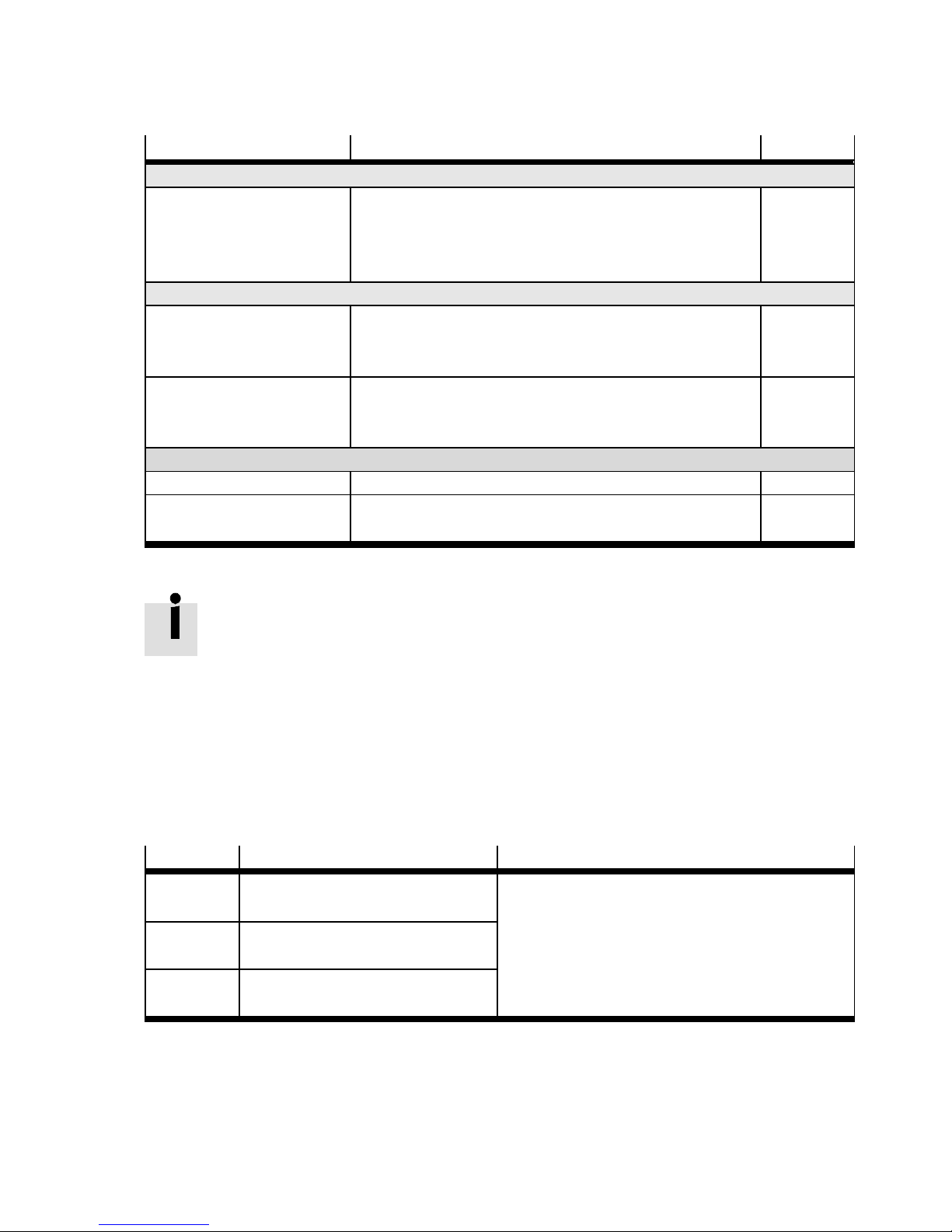
6Functions
Function PolarityDescription
Position t rigger
Position t rigger 1 … 4 The position triggers can be used to pass on information
High active
about the logical status of position triggers, rotor position triggers and cam controller units to the digital outputs.
Teach
Acknowledge teac h The signal goes to Low with the rising edge at the Teach
Low active
input and back to High with the falling edge at the Teach
input.
Saving process in operation The signal goes to High as soon as a saving procedure is
High active
started and is extinguished automatically after the saving
process has been completed.
Functional safety module
STO active Signals that safe status STO ( S afe torque off ) is active. High active
STO requested Signals that safe status STO (Safe torque off ) has been
High active
requested.
Tab. 6.28 Function overview of the digital outputs
The digital outputs “STO active” and “STO requested” must not be used in a
safety-directed manner.
Analogue inputs
Through the analogue inputs, setpoint values can be specified as controller input data via a correspondingly scaled input signal.
The setting of the function is dependent on the number of inputs used, the selected control interface
and the selected operating mode/function.
Analogue inputs — configuration
Input
AIN0 16 bit, high resolution, differential
Resolution Level
+10 VDC … –10 VDC
(Digital filter)
AIN1 10 bit, single-ended
(optional: DIN12)
AIN2 10 bit, single-ended
(optional: DIN13)
Tab. 6.29 Analogue inputs
Festo – GDCP-CMMP-M3-FW-EN – 1203NH 69
Page 70

6Functions
The specified value defines how the relevant input signal is converted into a torque, a speed or a
positioning setpoint value. Input voltages in the value range from –10 V … +10 V are processed.
• Specify in the respective registers in the FCT which value of the respective input variables corresponds to an input voltage of 10 V. The scaled range corresponds to a linear characteristic curve
symmetric to the zero point (e.g. –1000 R/min … +1000 R/min).
Correction
With an externally specified voltage 0 volt, an undesired setpoint value can still be generated due to
voltage differences. For zero balancing, you can manually enter an offset in the FCT or execute synchronisation automatically (recommendation).
Through zero balancing, the scaled range is divided asymmetrically ( example Fig. 6.8:
–750 … +1250 R/min).
Procedure for “A utomatic offset calibration”:
1. Connect the input with the potential corresponding to the setpoint value = 0.
2. Now carry out the “Automatic offset calibration” via FCT.
Analogue outputs
To configure the analogue outputs (AOUT):
• Select the respective desired output signal, e.g. setpoint or actual value of the controlled variable in
the FCT.
• Adjust the required settings and values (scaling, numerical overflow limitation) of the outputs used.
Analogue monitor
The motor controller has two analogue outputs AOUT 0 and AOUT 1 for output, e.g. of controlled variables, which can be represented with an external oscilloscope. The output voltage lies in the range of
-10 V to +10 V.
• Select the output variable that should be output through the analogue monitor.
• For output variable “Fixed clamping value”: In the “spanning value” field, set the voltage that
should remain constant at the output.
• For other output variables: In the “Scaling” field, set which value of the selected size corresponds to
an output voltage of 10 V.
Output variables (AOUT0, AOUT1)
Axis variables – Speed setpoint value
– Speed ac tual value
– Position setpoint
– Position actual value
Values for current – Effective current setpoint
– Effective current ac tual value
– Reactive current setpoint value
– Reactive current actual value
– Phase Current
70 Festo – GDCP-CMMP-M3-FW-EN – 1203NH
Page 71

6Functions
Output variables (AOUT0, AOUT1)
Additional signals – Rotor Position
– Intermediate circuit voltage
– Fixed voltage level
Tab. 6.30 Output variables
Overflow limitation activated
The numerical overflow limitation limits the voltage values U calculated corresponding to the scaling to
the range +10 V … -10 V.
Overflow limitation not activated
In case of overflow of the range limit + 10 V, the output voltage jumps to (–10 V +ΔU).
In case of overflow of the range limit -10 V, the output voltage jumps ( + 10 V -Δ U).
6.7.8 Supported encoder systems
The following encoder systems are supported by the motor controller CMMP-AS-...-M3:
Type
Remark Protocol Interface
Heidenhain Endat encoder
ROC 400
ECI 1100/1300
Single-turn absolute encoder
with/without analogue signal
ECN
100/400/1100/1300
ROQ 400
EQI 1100/1300
Multi-turn absolute encoder
with/without analogue signal
EQN
100/400/1100/1300
LC 100/400 Absolute length measurement
equipment
Stegmann HIPERFACE Encoder
SCS60/70 S CM60/70 Single- / multi-turn encoder with
analogue incremental signal.
Line count 512 (fixed). Number
of multi-turn revolutions: +/-
2048 R.
SRS50/60/64 SCKxx
SRM50/60/64 SCLxx
Single- / multi-turn encoder with
analogue incremental signal.
Line count 1024 (fixed). Number
of multi-turn revolutions: +/-
2048Uxx=25/35/40/45/
50 / 53
EnDat 2.1 (01/21)
[X2B]
EnDat 2.2 (22)
EnDat 2.1 (01/21)
[X2B]
EnDat 2.2 (22)
EnDat 2.1 (01)
[X2B]
EnDat 2.2 (22)
HIPERFACE [X2B]
HIPERFACE [X2B]
Festo – GDCP-CMMP-M3-FW-EN – 1203NH 71
Page 72

6Functions
Type InterfaceProtocolRemark
SKS36 SKM36 Single- / multi-turn encoder with
analogue incremental signal.
Line count 128 (fixed). Number
of multi-turn revolutions:
+/- 2048 R
SEK37/52 SEL37/52 Single- / multi-turn encoder with
analogue incremental signal. Li n e
count 16 (fixed). Number of multiturn revolutions: +/- 2048 R
L230 Absolute length measuring sys-
tem with analogue incremental
signal. Resolution: 156.25 μm.
Measuring length max. approx.
40 m
Yaskawa ∑-ENCODER
∑(sigma1) Digital incremental encoder with
zero-pulse
Analogue incremental encoders
ROD 400
ERO 1200/1300/1400
Heidenhain, encoder with zero
and reference pulse
ERN
100/400/1100/1300
Digital incremental encoders
CDD50 Stegmann encoder with Hall
sensors
Resolver
Standard Transmission ratio type 0.5 +-
10 %, Input supply type 7 Vrms
HIPERFACE [X2B]
HIPERFACE [X2B]
HIPERFACE [X2B]
Yaskawa OEM protocol [X2B]
– [X2B]
– [X2B]
– [X2A]
Tab. 6.31 Supported encoder systems
72 Festo – GDCP-CMMP-M3-FW-EN – 1203NH
Page 73

7 Dynamic response
7 Dynamic response
7.1 PFC for increased i ntermediate circuit voltage
The motor controllers CMMP-AS-C2-3A-M3 and CMMP-AS-C5-3A-M3 with single-phase supply are intended for connection to the 230 VAC mains grid and are equipped with an active PFC step (Power
Factor Control). The PFC stage is an active mains power converter that is required for conformance to
the relevant standards for limiting mains grid harmonics. The PFC stage also performs ac tive regulation
of the intermediate c ircuit voltage. The PFC step operates using the boost chopper principle and
provides a regulated nominal intermediate voltage of 380 VDC. This voltage is independent of the quality of the mains voltage, also when the mains voltage fluctuates or with mains grid undervoltage. This is
a significant advantage when selecting the servo motor because, compared to a device with passive
mains feed, higher speeds are achievable or a higher torque c onstant can be selected. Further, due to
the ac tive PFC step, the device is also appropriate for wide-range operation down to 100 VAC mains
voltage; but the limitation of the effective power consumption due to the permissible maximum c urrent
of the PFC step must be observed.
Note
The PFC step of all motor controllers connected to the intermediate circuit must be
disabled if motor controllers are coupled via the intermediate circuit.
Note
It must be ensured that the reference potential (N) is switched before or simultaneously
with the phase (L1). This c an be achieved through:
– unswitched reference potential (N)
– use of fuses with leading N when switching of the reference potential is not spe-
cified.
7.1.1 Switch-on behaviour:
As soon as the motor controller is provided with mains voltage, the intermediate circuit is charged
(< 1 s) via the braking resistors, with the intermediate circuit relay deactivated. The PFC stage is not
switched on at this point.
After the intermediate circuit has been successfully pre-charged, the relay engages and the intermediate circuit is "hard" connected to the mains supply. The PFC stage is then activated and the intermediate stage is loaded with the full voltage.
If the intermediate c ircuit voltage is too low after successful charging, because the mains input voltage
lies below the permitted level for PFC operation, the PFC stage remains blocked and a warning is displayed on the sever-segment display.
If the motor controller is supplied with less than the nominal voltage of 230 VAC, after pre-loading is
completed, a power reduction for the PFC step is calculated based on the achieved intermediate circuit
voltage.
Festo – GDCP-CMMP-M3-FW-EN – 1203NH 73
Page 74
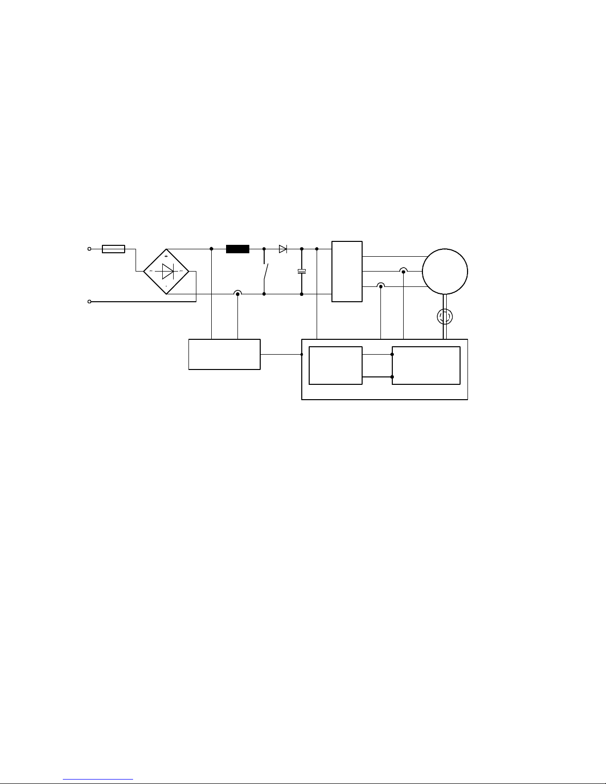
7 Dynamic response
7.1.2 Behaviour under normal operation and control properties
In operation, the power consumption of the motor controller from the mains network is monitored via
the PFC step. The mains current is regulated by an analogue control circuit so that the shape of the
curve reflects that of the mains voltage sinewave and the phase shift is 0°. The amplitude is adjusted
according to the specified effective power.
A higher-level digital controller regulates the in termediate circuit voltage to an average v alue of approx.
360 VDC. To relieve the relatively sluggish voltage regulation under load changes (acc eleration/braking
of the drive), the effective power delivered to the motor from the motor controller is measured and
used to pre-control the PFC step.
F
100 V … 230 V AC
±10
U_in I_in U_ZK i_u i_v Angle encoder
IC for Power
Factor Control
L
T8
PWM
D
3~
C
PWM
Voltage
regulator
u_q
i_q
Microcontroller
Drive
regulator
M
3~
Fig. 7.1 Schematic structure of the PFC stage
Control e ncompasses the following variables:
– Digital control of the intermediate circuit voltage to an average of approx. 380 VDC
– Analogue control of the mains input current
– Maintenance of a sinewave mains current under stationary load c onditions
– Operation with cosü > 0.97 at rated operation (at the rated power of the PFC step)
The parameterisation program can be used to switch the PFC control on or off. When the PFC is deactivated, the intermediate circuit behaves like a normal intermediate circuit with an upstream bridge rectifier.
The intermediate circuit voltage is usua lly regulated t o a constant average value that, under stationary
load conditions, is independent of the specified effective power of the motor.
7.2 Extended sine modulation for increased output voltage
With the CMMP-AS-...-M3 motor c ontroller, the cycle rate in the current regulator circuit is set to a cycle
time of 125 μs or 62.5 μs. To minimise switching losses, the pulse width modulation clock frequency
can be set to half that of the current regulator clock frequency.
74 Festo – GDCP-CMMP-M3-FW-EN – 1203NH
Page 75
7 Dynamic response
The motor controller CMMP-AS-...-M3 also has a sine-wave modulation or, alternatively, an extended
sine-wave modulation (with third harmonic wave). This increases the effective converter output
voltage. The modulation type can be selected using the parameterising software. The standard setting
is extended sine-wave modulation.
7.3 Variable cycle times, current, speed and position controller
The motor controllers of the CMMP-AS-...-M3 series permit a switchable current control c ycle time.
From these settings are derived the cycle times for the speed and position controller as well as the
interpolation time.
Faster cycle times permit lower reaction times and an improved control dynamic (depending on the
application, higher possible closed-loop gain or lower “overshooting” of the position actual values).
The following table includes the pulse-width modulation frequencies supported by the CMMP-AS-...-M3
and their related cycle times:
PWM
frequency
Scanning
frequency of
current control
Cycletimeof
current control
Cycle time of
speed
adjustment
Cycletimeof
position
control
Interpolation
time
4kHz 8kHz 125 μs 250 μs 500 μs 1000 μs
8kHz 8kHz 125 μs 250 μs 500 μs 1000 μs
8kHz 16 kHz 62.5 μs 125 μs 250 μs 500 μs
16 kHz 16 kHz 62.5 μs 125 μs 250 μs 500 μs
Tab. 7.1 PWM frequencies and cycle times
The PWM frequency can be set in the parameterisation software FCT with the option “Half output stage
frequency”.
With higher PWM frequencies, the result is reduced nominal/peak currents of the power
sections. Derating tables Technical data GDCP-CMMP-M3-HW-....
Festo – GDCP-CMMP-M3-FW-EN – 1203NH 75
Page 76

8 Service functions and diagnostic messages
8 Service functions and diagnostic messages
8.1 Protective and service functions
8.1.1 Over view
The motor controller CMMP-AS-...-M3 has a complex array of sensors that monitor the controller section, power output stage, motor and external communication to ensure that they function excellently.
All diagnostic events which occur are saved in th e internal diagnostic memory. The diagnostic memory
in the motor controller has a two-tier architecture:
– All messages since the motor controller was last switched on are saved in the temporary memory
(these are lost in the event of a power failure).
– The messages are permanently saved in the permanent memory of the family CMMP-AS-...-M3 (se-
cure in the event of a power failure). This memory consists of 2 segments that are filled one after
the other. When both segments are full, the older segment is automatically cleared. This means that
a sort o f ring memory is available for the permanently saved messages.
Most errors cause the controller section to switch off the motor c ontroller and the power end stage.
The motor controller can only be switched on again when the error has been eliminated and then acknowledged.
For some of the diagnostic messages, t he behaviour of the motor controller can be parameterised.
Possible reactions:
– PS off Switch off power section immediately
– MCStop Stop with maximum peak current
– QStop Quick stop with the deceleration specified on the “Axis” ( FCT) page
– Warn Output of a warning
– Ignore Ignore diagnostic message
A complex system of sensors and numerous monitoring functions ensure operational reliability:
– Measurement of the motor temperature
– Measurement of th e power output stage temperature
– Earth fault detection (PE)
– Detection of short-circuits between two motor phases
– Detection of overvoltages in the intermediate circuit
– Detection of faults in the internal voltage supply
– Collapse of supply voltage
8.1.2 Phases and mains failure detection with 3-phase motor controllers
The motor controller CMMP-AS-...-M3 detects a phase failure in three-phase operation (phase failure
detection) or fa ilure of several phases (network failure detection) of the mains supply at the device.
8.1.3 Overload current and short-circuit monitoring
Overload current and short-circuit monitoring detects shor t circuits between two motor phases and
short circuits at the motor output terminals against the positive and negative reference potential of the
intermediate circuit and against PE. If the error control detects overload current, the power output
stage shuts down immediately, guaranteeing protection against short circuits.
76 Festo – GDCP-CMMP-M3-FW-EN – 1203NH
Page 77

8 Service functions and diagnostic messages
8.1.4 Overvoltage monitoring for the intermediate circuit
The overvoltage monitoring for the intermediate circuit takes effect as soon as the intermediate circuit
voltage exceeds the operating voltage range. The power output stage is then deactivated.
8.1.5 Temperature monitoring for the heat sink
The heat sink temperature of the output end stage is measured with a linear temperature sensor. The
temperature limit varies from device to device. A temperature warning is triggered at about 5°C below
the limit value.
8.1.6 Monitoring of the motor
The motor controller CMMP-AS-...-M3 has the following protective functions for monitoring the motor
and the connected shaft encoder:
Protective func-
Description
tion
Monitoring the
shaft encoder
An error of the shaft encoder causes the power output stage to be switched off.
For the resolver, for example, the tracking signal is monitored. For increment
generators, the commutator signals are checked. Generally true for intelligent
encoders is that their various error messages are evaluated and reported to the
CMMP-AS-...-M3 as common error E 08-8.
Measurement and
monitoring of the
motor temperature
The motor controller CMMP-AS-...-M3 has a digital and an analogue input for
recording and monitoring the motor temperature. The following temperature
sensors can be selected:
– [X6]: Digital input for PTCs, N/C contacts and N/O contacts.
– [X2A] and [X2B]: N/C contact and KTY series analogue sensors. ( Only for
parameterisation of user-defined motors)
Tab. 8.1 Protective functions of the motor
8.1.7 I
The motor controller CMMP-AS-...-M3 has I
2
t monitoring
2
t monitoring to limit the average power loss in the power
end stage and in the motor. Since the power loss that occurs in the power electronics and the motor
can, in the worst case , grow at a rate equal to the square of the flowing current, the squared current
value is taken as a measure for the power loss.
8.1.8 Power monitoring for the brake chopper
The braking resistors are monitored on the firmware side through the function I
the output monitoring reaches “I²t brake chopper” of 100 %, the output of the internal braking resistor
is switched back to rated output.
As a result of this switch back, the error “E 07-0” “Overvoltage in the intermediate c ircuit” is generated
if the braking process is not yet finished and (too much) energy is fed back to the controller.
In a ddition, the brake choppe r is protected by means of overcurrent detection. If a shor t circuit is detected via the braking resistor, the brake chopper controller is switched off.
Festo – GDCP-CMMP-M3-FW-EN – 1203NH 77
2
t brake chopper. When
Page 78
8 Service functions and diagnostic messages
8.1.9 Commissioning status
Motor controllers sent to Festo for servicing are loaded with other firmware and parameters for testing
purposes.
Before it is commissioned again at the location of the final customer, the motor controller
CMMP-AS-...-M3 must be parametrised. The parametrisation software queries the commissioning
status and prompts the user to parameterise the motor controller. At the same time, the device signals
that it is ready for operation but has not yet been parametrised by displaying “A” on the seven-segment
display.
8.1.10 Rapid discharge of the intermediate circuit
When a mains supply failure is detected, the intermediate circuit is quickly discharged within the safety
time specified in EN 60204-1.
Delayed connection of the brake chopper by power class in parallel operation and when a mains failure
occurs ensures that the main energy during rapid discharge of the intermediate circuit is taken over
through the braking resistors of the higher power classes.
But the rapid discharge can be ineffective in certain device constellations, especially
when several motor controllers are connected in parallel in the intermediate circuit or a
brake resistance is not connected. The motor controllers may carry dangerous voltage for
up to 5 minutes after being switched off (capacitor residual charge).
8.2 Operating mode and error messages
8.2.1 Operating mode and error display
The motor controller CMMP-AS-...-M3 has three LEDs and one seven-segment display on the front for
showing the operating statuses.
Element
Seven-segment display – Displays the operating mode and a coded error number in
LED1 Green Operating status
LED2 Green Controller enable
LED3 Yellow CAN bus status display
RESET button – Hardware reset for the processor
Tab. 8.2 Display components and RESET pushbutton
LED col-
Function
our
case of error.
Red Error
78 Festo – GDCP-CMMP-M3-FW-EN – 1203NH
Page 79
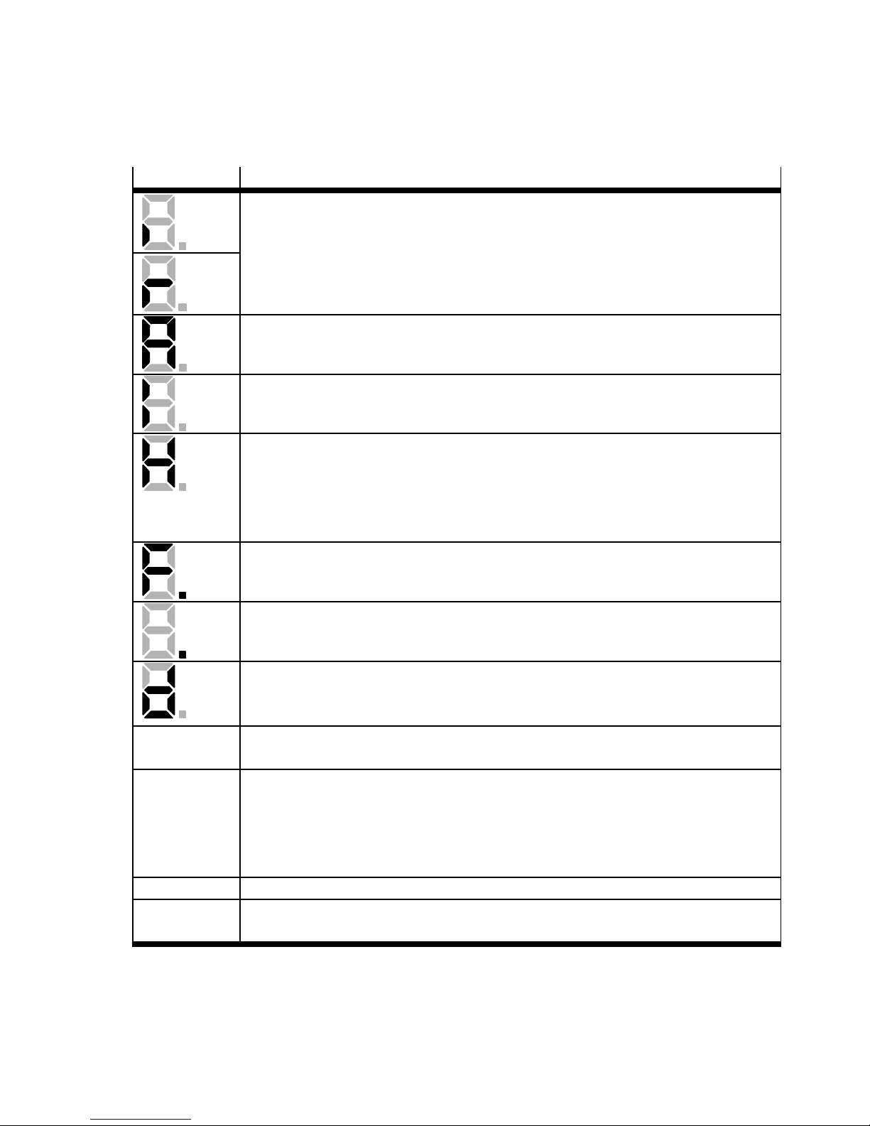
8 Service functions and diagnostic messages
8.2.2 Seven-segment display
The display and the meaning of the symbols shown are illustrated in the following table:
Display
Significance
The outer segments “rotate” on the display in the speed control operating mode.
The display depends on the current actual position or speed.
With active controller enable, the centre bar is also active.
The motor controller CMMP-AS-...-M3 must still be parameterised.
(Seven-segment display = “A”)
Controlled t orque mode.
(Seven-segment display = “I”)
“H”: The motor controller is in the “safe status”.
This does not mean the same as the information about the status of the safety function STO (Safe Torque Off ). This can only be read at the LED of the safety module.
For the “unsafe status”, no special display is intended; the standard status displays
of the motor controller are depicted.
“F.”:
Signals that firmware is currently being loaded into the flash.
“.”:
Bootloader active
“d”:
Signals that a parameter record is currently being loaded from the SD card to the
controller.
P xxx Positioning (“xxx” is the position number)
The numerals are shown in succession
PH x Homing. “x” stands for the respective phase of the homing:
x = 0: search phase
x = 1: crawl phase
x=2:runtozeroposition
The numerals are shown in succession
E xxy Error message with main index “xx” and sub-index “y”
-xxy- Warning message with main index “xx” and sub-index “y”. Warnings are shown at
least twice on the seven-segment display.
Tab. 8.3 Operating mode and error display
Festo – GDCP-CMMP-M3-FW-EN – 1203NH 79
Page 80
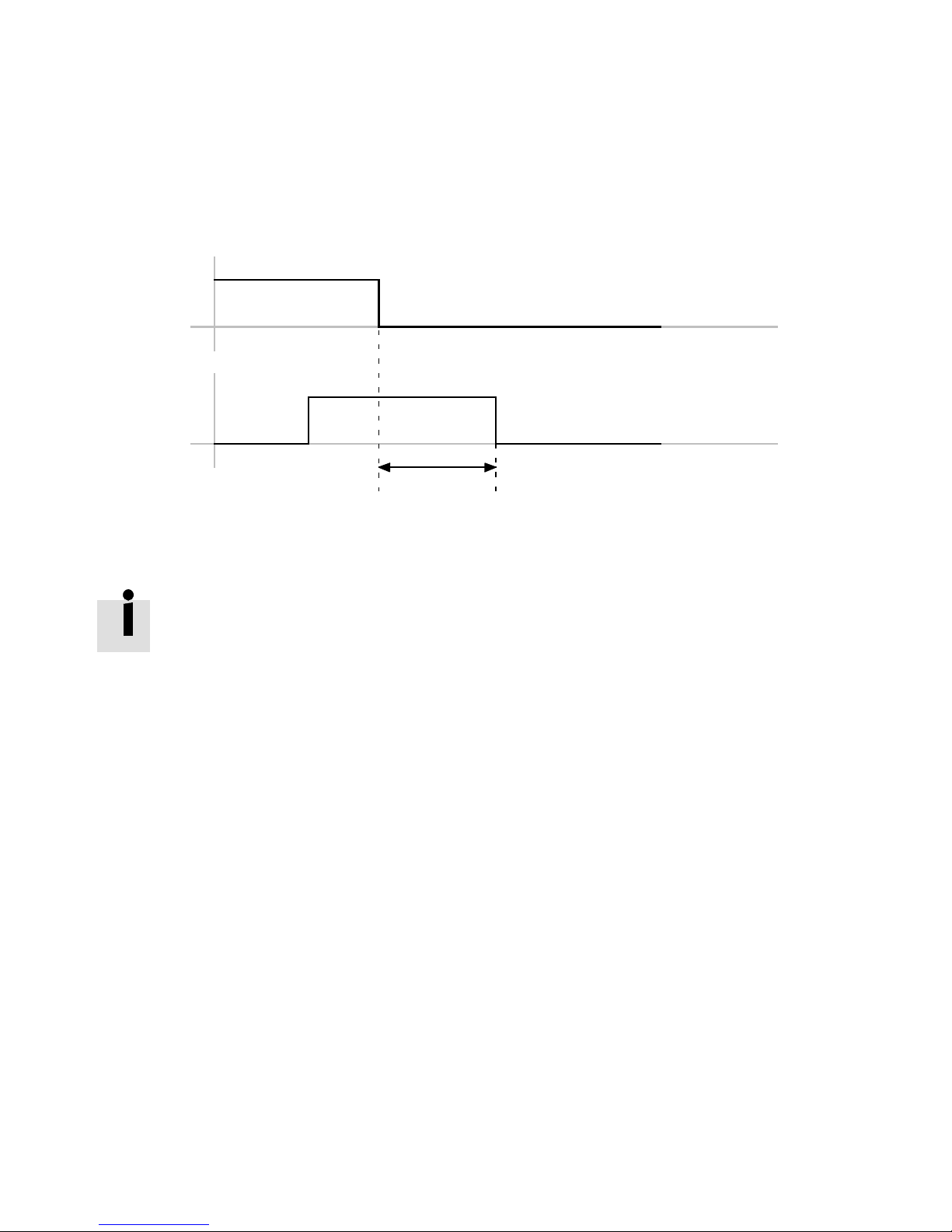
8 Service functions and diagnostic messages
8.2.3 Acknowledgement of error messages
Error messages can be acknowledged through:
– the parametrisation interface
– the fieldbus (control word)
– a decreasing edge at DIN5 [X1]
Controller
enable
DIN5 [X1]
“Error active”
1
1L80 ms
Fig. 8.1 Timing diagram: acknowledge error
Diagnostic events which are parametrised as warnings are automatically acknowledged
when the cause is no longer on hand.
8.2.4 Diagnostic messages
The significance and their measures for diagnostic messages are summarised in the following chapter:
( chapter A Diagnostic messages).
80 Festo – GDCP-CMMP-M3-FW-EN – 1203NH
Page 81

A Diagnostic messages
A Diagnostic messages
If an error occurs, the motor c ontroller CMMP-AS -...-M3 shows a diagnostic message cyclically in the
seven-segment display of the motor c ontroller CMMP-AS-...-M3. An error message consists of an E (for
Error), a main index and sub-index, e.g.: E 0 1 0.
Warnings have the same number as an error message. In contrast to error messages, however, warnings are preceded and followed by hyphens, e.g. -170-.
The following table summarises the significance of the diagnostic messages and the actions to be
takeninresponsetothem:
Column
Code The Code column includes the error code (Hex) via CiA 301
No. Main index and sub-index of the diagnostic message.
Message Message that is displayed in the F CT.
Cause Possible causes for the message.
Action Action by the user.
Reaction The Reaction column includes the error response (default setting, partially
Tab. A.1 Explanations on the table “Diagnostic messages of the CMMP-AS-...-M3”
The following table includes the error messages corresponding to the firmware versions at the time this
document was printed.
Significance
Display in the indicator, in FCT or diagnostic memory via FHPP.
configurable):
– PS off (switch off output stage),
– MCStop (fast stop with maximum current),
– QStop ( fast stop with parametrised ramp),
–Warn(Warning),
– Entry (Entry in diagnostic memory),
–Ignore(Ignore).
Festo – GDCP-CMMP-M3-FW-EN – 1203NH 81
Page 82

A Diagnostic messages
Diagnostic messages of the CMMP-AS-...-M3
No. Code Message Causes Actions Reac tion
00-0 – Inv alid error Information: An in valid er-
ror entry (corrupted) was
found in the diagnostic
memory marked with this
error number.
Thesystemtimeentryis
set to “0”.
00-1 – Inv alid error de-
tected and corrected
Information: An invalid error entry (corrupted) was
found in the diagnostic
memory and corrected.
The additional information contains the original
error number.
Thesystemtimeentry
contains the address of
the corrupted error number.
00-2 – Error cleared Information: Active errors
were acknowledged.
01-0 6180hStack overflow Incorrect firmware?
Sporadic high processor
load due to cycle time being too short and special
compute-bound processes (save parameter
set, etc.).
– Entry
– Entry
– Entry
• Load an approved
PS off
firmware.
• Reduce the processor
load.
• Contact Technical
Support.
82 Festo – GDCP-CMMP-M3-FW-EN – 1203NH
Page 83

A Diagnostic messages
Diagnostic messages of the CMMP-AS-...-M3
No. ReactionActionsCausesMessageCode
02-0 3220hUndervoltage in
intermediate circuit
03-0 4310hAnalogue motor
overtemperature
03-1 4310hDigital motor
overtemperature
03-2 4310hAnalogue motor
overtemperature:
broken wire
Intermediate circuit
voltage falls below the
parametrised threshold.
Error priority set too
high?
Motor overloaded, temperature too high.
– Suitable sensor or
sensor characteristics
parametrised?
– Sensor defective?
Motor overloaded, temperature too high.
– Suitable sensor or
sensor characteristics
parametrised?
– Sensor defective?
The measured resistance
value is above the
threshold for wire break
detection.
• Quick discharge due
to switched-off mains
1)
supply.
• Check power supply.
• Couple intermediate
circuits if technically
permissible.
• Check intermediate
circuit voltage (measure).
If there is overloading:
• Check parameters
(current regulator,
current limits).
• Check the parametrisation of the sensor
or the sensor characteristics.
If the error persists when
the sensor is bypassed:
device defective.
If there is overloading:
• Check parameters
(current regulator,
current limits).
• Check the parametrisation of the sensor
or the sensor characteristics.
If the error persists when
the sensor is bypassed:
device defective.
• Check the connecting
cables of the temperature sensor for wire
breaks.
• Check the parametrisation (threshold
value) for wire break
detection.
Configurable
QStop
Configurable
Configurable
1) Supplemental information in PNU 203/213:
To p 16 bits: Status number o f internal state machine
Bottom 16 bits: Intermediate circuit voltage (internal scaling approx. 17.1 digit/V).
Festo – GDCP-CMMP-M3-FW-EN – 1203NH 83
Page 84

A Diagnostic messages
Diagnostic messages of the CMMP-AS-...-M3
No. ReactionActionsCausesMessageCode
03-3 4310hAnalogue motor
overtemperature:
short circuit
04-0 4210hPower end stage
overtemperature
04-1 4280hIntermediate cir-
cuit overtemperature
05-5 – Voltage failure in-
terface Ext1/Ext2
05-6 – Voltage failure
[X10], [X11]
05-7 – Safety module in-
ternal voltage
failure
05-8 – Failure of internal
voltage 3
The measured resistance
value is below the
threshold for short circuit
detection.
Device is overheated
– Temperature display
plausible?
– Device fan defective?
– Device overloaded?
Device is overheated
– Temperature display
plausible?
– Device fan defective?
– Device overloaded?
Defect on the plugged-in
interface
Overloading through connected peripherals
Defect on the safety module
Defect in the motor controller
• Check the connecting
cables of the temperature sensor for wire
breaks.
• Check the parametrisation (threshold
value) for short circuit
detection.
• Check installation
conditions; are the
control cabinet fan filters dirty?
• Check the drive layout
(due to possible overloading in continuous
duty).
• Check installation
conditions; are the
control cabinet fan filters dirty?
• Check the drive layout
(due to possible overloading in continuous
duty).
Interface replacement
R epair by the manufacturer.
• Check pin allocation
of the connected peripherals.
• Short circuit?
Interface replacement
R epair by the manufacturer.
Internal defect Repair
by the manufacturer.
Configurable
Configurable
Configurable
PS off
PS off
PS off
PS off
84 Festo – GDCP-CMMP-M3-FW-EN – 1203NH
Page 85

A Diagnostic messages
Diagnostic messages of the CMMP-AS-...-M3
No. ReactionActionsCausesMessageCode
05-9 – Encoder supply
defective
05-0 5114hFailure of internal
voltage 1
05-1 5115hFailure of internal
voltage 2
05-2 5116hFailure of driver
supply
05-3 5410hUndervoltage dig.
I/O
Back measurement of the
encoder voltage not OK.
Monitoring of the internal
power supply has recognised undervoltage. This
is either due to an internal defect or an overload/
short circuit caused by
connected peripherals.
Monitoring of the internal
power supply has recognised undervoltage. This
is either due to an internal defect or an overload/
short circuit caused by
connected peripherals.
Monitoring of the internal
power supply has recognised undervoltage. This
is either due to an internal defect or an overload/
short circuit caused by
connected peripherals.
Defective peripheral
device?
Internal defect Repair
by the manufacturer.
• Separate device from
theentireperipheral
equipment and check
whether the error is
still present after reset. If yes, then there
is an internal defect
R epair by the manufacturer.
• Separate device from
theentireperipheral
equipment and check
whether the error is
still present after reset. If yes, then there
is an internal defect
R epair by the manufacturer.
• Separate device from
theentireperipheral
equipment and check
whether the error is
still present after reset. If yes, then there
is an internal defect
R epair by the manufacturer.
• Check connected peripherals for short circuit / rated loads.
• Check connection of
the brake (connected
incorrectly?).
PS off
PS off
PS off
PS off
PS off
Festo – GDCP-CMMP-M3-FW-EN – 1203NH 85
Page 86

A Diagnostic messages
Diagnostic messages of the CMMP-AS-...-M3
No. ReactionActionsCausesMessageCode
05-4 5410hOverload current
dig. I/O
06-0 2320hShort circuit in
output stage
Defective peripheral
device?
– Faulty motor, e.g.
winding short circuit
due to motor overheating or short to PE
inside motor.
– Short circuit in the
cable or the connecting plugs, i.e. short
circuit between motor
phases or to the
screening/PE.
– Output stage defect-
ive (short circuit).
– Incorrect paramet-
erisation of the current regulator.
• Check connected peripherals for short circuit / rated loads.
• Check connection of
the brake (connected
incorrectly?).
Dependent on the status
of the system
footnote
2)
,
cases a) … f)
PS off
PS off
2) Actions:
Case a) Error only with active brake chopper: Check external braking resistor for short circuit or insufficient resistance value.
Check circuitry of the brake chopper output at the motor controller (bridge, etc.).
Case b) Error message immediately when the power supply is connected: internal short circuit in the output stage (short circuit
of a complete half-bridge). The motor controller can no longer be connected to the power supply; the internal (and possibly
external) fuses are tripped. Repair by the manufacturer is necessary.
Case c) Short circuit error message only when the output stage or controller enable is issued.
Case d) Disconnection of motor plug [X6] directly on the motor controller. If the error still occurs, there is a fault in the motor
controller. Repair by the manufacturer is necessary.
Case e) If the error only occurs when the motor cable is connected: check the motor and cable for short circuits, e.g. with a
multimeter.
Case f) Check parametrisation of the current regulator. Oscillations in an incorrectly parametrised current regulator can generate
currents up to the short circuit threshold, usually clearly audible as a high-frequency whistling. Verification, if necessary, with the
trace in the FCT (actual active current value).
86 Festo – GDCP-CMMP-M3-FW-EN – 1203NH
Page 87

A Diagnostic messages
Diagnostic messages of the CMMP-AS-...-M3
No. ReactionActionsCausesMessageCode
06-1 2320hOverload current
brake chopper
Overload current at the
brake chopper out put.
07-0 3210hOvervoltage Braking resistor is over-
loaded; too much braking
energy which cannot be
dissipated quickly
enough.
– Resistor capacity is in-
correct?
– Resistor not connec-
ted correctly?
08-1 – Sense of rotation
of the serial and
incremental position evaluation is
not identical
Only encoder with serial
position transmission
combined with an analogue SIN/COS signal
track: The direction of rotation of encoder-internal
position determination
and incremental evaluation of the analogue
track system in the motor
controller are the wrong
way around.
Footnote
3)
• Check external braking resistor for short
circuit or insufficient
resistance value.
• Check circuitry of the
brake chopper output
at the motor controller (bridge, etc.).
•Checkthedesignof
the braking resistor;
resistance value may
be too great.
• Check the connection
to the braking resistor
(internal/external).
• Swap the following
signals on the [X2B]
angle encoder interface (the wires in the
connecting plug must
be changed around),
observing the technical data for the angle
encoder where applicable:
–SwapSIN/COStrack.
– Swap the SI N+/SIN-
or COS+/COS- signals,
as applicable.
PS off
PS off
Configurable
3) The encoder counts internally, for example positively in clockwise rotation wh ile the incremental evaluation counts in negative
direction with the same mechanical rotation. The interchange of the direction of rotation is detected mechanically at the first
movement of over 30° and the error is triggered.
Festo – GDCP-CMMP-M3-FW-EN – 1203NH 87
Page 88

A Diagnostic messages
Diagnostic messages of the CMMP-AS-...-M3
No. ReactionActionsCausesMessageCode
08-0 7380hResolver angular
encoder error
08-2 7380hError in increment
generator tracking signal Z0
08-3 7383hError in increment
generator tracking signal Z1
Resolver signal amplitude
is faulty
Signal amplitude of the
Z0 track at [X2B] is faulty.
–Angleencodercon-
nected?
– Angle encoder c able
defective?
– Angle encoder defect-
ive?
Signal amplitude of the
Z1 track on X2B is faulty.
–Angleencodercon-
nected?
– Angle encoder c able
defective?
– Angle encoder defect-
ive?
Step-by-step approach
footnote
4)
,a)…c):
Check configuration of
angle encoder interface:
a) Z0 evaluation activ-
ated, but no track signals connected or on
5)
hand.
b) Encoder signals
faulty?
c) Test with another en-
coder.
Tab. A.3, Page 128.
Check configuration of
angle encoder interface:
a) Z1 evaluation activ-
ated but not connected.
b) Encoder signals
faulty?
c) Test with another en-
coder.
Tab. A.3, Page 128.
Configurable
Configurable
Configurable
4) a) If possible, test with a different (error-free) resolver (replace the connecting cable too). If the error still occurs, there is a fault
in the motor controller. Repair by manufacturer required.
b) If the error occurs only with a special resolver and its connecting cable: Check resolver signals (carrier and SIN/COS signal),
see specification. If the signal specification is not maintained, the resolver must be replaced.
c) If the error recurs sporadically, check the screening connection or check wh ether the resolver simply h as an insufficient
transmission ratio (standard resolver: A = 0.5).
5) e.g. EnDat 2.2 or EnDat 2.1 without analogue track.
Heidenhain encoder: order codes EnDat 22 and EnDat 21. With these encoders there are no incremental signals, even when the
cables are connected.
88 Festo – GDCP-CMMP-M3-FW-EN – 1203NH
Page 89

A Diagnostic messages
Diagnostic messages of the CMMP-AS-...-M3
No. ReactionActionsCausesMessageCode
08-4 7384hDigital increment-
al encoder track
signals error
[X2B]
08-5 7385hError in increment
generator of Halleffect encoder
signals
08-6 7386hAngle encoder
communication
fault
08-7 7387hSignal amplitude
of incremental
tracks faulty
[X10]
Faulty A, B, or N track signals at [X2B].
–Angleencodercon-
nected?
– Angle encoder cable
defective?
–Angleencoder
defective?
Hall encoder signals of a
dig. inc. at [X2B] faulty.
–Angleencodercon-
nected?
– Angle encoder cable
defective?
– Angle encoder defect-
ive?
Communication to serial
angle encoders is disrupted (EnDat encoders,
HIPERFACE encoders,
BiSS encoders).
–Angleencodercon-
nected?
– Angle encoder cable
defective?
– Angle encoder defect-
ive?
Faulty A, B, or N track signals at [X10].
–Angleencodercon-
nected?
– Angle encoder cable
defective?
– Angle encoder defect-
ive?
Check the configuration
of the angle encoder interface. Proceed according to a) and b):
a) Encoder signals
faulty?
b) Test with another en-
coder.
Tab. A.3, Page 128.
Check the configuration
of the angle encoder interface. Proceed according to a) and b):
a) Encoder signals
faulty?
b) Test with another en-
coder.
Tab. A.3, Page 128.
Check configuration of
the angle generator interface: procedure corresponding to a) … c):
a) Serial encoder para-
metrised but not connected?
Incorrect serial protocol selected?
b) Encoder signals
faulty?
c) Test with another en-
coder.
Tab. A.3, Page 128.
Check the configuration
of the angle encoder interface. Proceed according to a) and b):
a) Encoder signals
faulty?
b) Test with another en-
coder.
Tab. A.3, Page 128.
Configurable
Configurable
Configurable
Configurable
Festo – GDCP-CMMP-M3-FW-EN – 1203NH 89
Page 90

A Diagnostic messages
Diagnostic messages of the CMMP-AS-...-M3
No. ReactionActionsCausesMessageCode
08-8 7388hInternal angle en-
coder error
Internal monitoring of the
angle encoder [X2B] has
detected an error and forwarded it via serial communication to the c ontroller.
– Declining illumination
intensity with visual
encoders
– Excess rotational
speed
–Angleencoder
defective?
If the error occurs
repeatedly, the encoder is
defective. Replace
encoder.
Configurable
90 Festo – GDCP-CMMP-M3-FW-EN – 1203NH
Page 91

A Diagnostic messages
Diagnostic messages of the CMMP-AS-...-M3
No. ReactionActionsCausesMessageCode
08-9 7389hAngle encoder at
[X2B] is not supported
Angle encoder type read
at [X2B], which is not supported or cannot be used
in the desired operating
mode.
– Incorrect or inappro-
priate protocol type
selected?
– Firmware does not
support the connected encoder model?
Depending on the
additional information of
the error message
footnote
6)
:
• Load appropriate firmware.
• Check/correct the
configuration for encoder evaluation.
• Connect an appropriate encoder type.
Configurable
6) Additional information (PNU 203/213):
0001: H I PE RFACE: encoder type is not supported by the firmware -> connect another encoder type or load more recent firmware,
if applicable.
0002: EnDat: The address space in which the encoder parameters would have to lie does not exist with the connected EnDat
encoder -> check the encoder type.
0003: EnDat: encoder type is not supported by the firmware -> connect another encoder type or load more recent firmware, if
applicable.
0004: EnDat: Encoder rating plate cannot be read from the connected encoder. -> Change encoder or load more recent firmware,
if applicable.
0005: EnDat: EnDat 2.2 interface parametrised, connected encoder supported but only EnDat2.1. -> Replace encoder type or
reparameterise to EnDat 2.1.
0006: EnDat: EnDat2.1 interface with analogue track evaluation parametrised, but according to rating plate the connected
encoder does not support track signals. -> Replace encoder or switch off Z0 track signal evaluation.
0007: Code length measuring system with EnDat2.1 connected, but parametrised as a purely serial encoder. Purely serial evalu-
ation is not possible due to the long response times of this encoder system. Encoder must be operated with analogue track
signal evaluation -> connect to analogue Z0 track signal evaluation.
Festo – GDCP-CMMP-M3-FW-EN – 1203NH 91
Page 92

A Diagnostic messages
Diagnostic messages of the CMMP-AS-...-M3
No. ReactionActionsCausesMessageCode
09-4 – EEPROM data: Er-
roneous custom
specific configuration
09-0 73A1hOld angle en-
coder parameter
set
09-1 73A2hAngle encoder
parameter record
cannot be decoded
Only for special motors:
The plausibility check returns an error, e.g. because the motor was repaired or exchanged.
Warning:
An encoder parameter set
in an old format was
found in the EEPROMof
the c onnected encoder.
This has been converted
and saved in the new
format.
Data in the EEPROM of
the angle encoder could
not be read completely, or
access to it was partly refused.
• If motor repaired:
Carry out homing
again and save in the
angle encoder, after
that ( !) save in the motor controller.
• If motor exchanged:
Parameterise the controller again, then
carry out homing
again and save in the
angle encoder, after
that ( !) save in the motor controller.
No action necessary at
this point. The warning
should not re-appear
when the 24 V supply is
switched back on.
The EEPROM of the encoder contains data
(communication objects)
which is not supported by
the loaded firmware. The
data in question is then
discarded.
• The parameter record
can be adapted to the
current firmware by
writing the encoder
data to the encoder.
• Alternatively, load appropriate (more recent) firmware.
Configurable
Configurable
Configurable
92 Festo – GDCP-CMMP-M3-FW-EN – 1203NH
Page 93

A Diagnostic messages
Diagnostic messages of the CMMP-AS-...-M3
No. ReactionActionsCausesMessageCode
09-2 73A3hUnknown version
of angle encoder
parameter record
09-3 73A4hDefective data
structure in angle
encoder parameter record
09-7 73A5hWrite-protected
angle encoder
EEPROM
Thedatasavedin
EEPROM are not
compatible with the
current version. A data
structure was found
whichisunabletodecode
the loaded firmware.
Data in EEPROM do not
match the stored data
structure. The data structure was identified as valid but may be corrupted.
Data cannot be saved in
the EEPROM of the angle
encoder.
Occurs with Hiperface encoders.
• Save the encoder
parameters again in
order to delete the
parameter record in
the encoder and replace it with a readable record (this will,
however, delete the
data in the encoder irreversibly).
• Alternatively, load appropriate (more recent) firmware.
• Save the encoder
parameters again in
order to delete the
parameter record in
the encoder and replace it with a readable record. If the error still occurs after
that, the encoder may
be faulty.
• Replace the encoder
as a test.
A data field in the encoder EEPROM is readonly (e.g. after operation
on a motor controller of
another manufacturer).
No solution possible, encoder memory must be
unlocked with an appropriate parametrisation
tool (from manufacturer).
Configurable
Configurable
Configurable
Festo – GDCP-CMMP-M3-FW-EN – 1203NH 93
Page 94

A Diagnostic messages
Diagnostic messages of the CMMP-AS-...-M3
No. ReactionActionsCausesMessageCode
09-9 73A6hAngle encoder's
EEPROM too
small
10-0 – Overspeed (spin
protection)
11-7 – Homing: error in
encoder difference monitoring
11-0 8A80hError when hom-
ing is started
11-1 8A81hError during hom-
ing
It is not possible to save
all the data in the
EEPROM of the angle
encoder.
• Reduce the number of
data records to be
saved. Please read
the documentation or
contact Technical Support.
– Motor racing (“spin-
ning”) because the
commutation angle
offset is incorrect.
– Motor is parametrised
• Check the commutation angle offset.
• Check the limit value
setting in the parameters.
correctly but the limit
for spinning protection is set too low.
Deviation between the
actual position value and
commutation position is
too great. External angle
encoder not connected or
faulty?
• Deviation fluctuates,
e.g. due to gear backlash; cut-off threshold
may need to be increased.
• Check connection of
the actual value encoder.
Controller enable missing. Homing can only be star-
ted when closed-loop
controller enable is active.
• Check the condition or
sequence.
Homing was interrupted,
e.g. by:
– Withdrawal of control-
ler enable.
– Reference switch is
beyond the limit
switch.
– External stop signal (a
• Check homing sequence.
• Check arrangement of
the switches.
• If applicable, lock the
stop input during
homing if it is not desired.
phase was aborted
during homing).
Configurable
Configurable
Configurable
Configurable
Configurable
94 Festo – GDCP-CMMP-M3-FW-EN – 1203NH
Page 95

A Diagnostic messages
Diagnostic messages of the CMMP-AS-...-M3
No. ReactionActionsCausesMessageCode
11-3 8A83hHoming: timeout The parametrised maxim-
um time for the homing
run was exceeded before
the homing run was completed.
11-4 8A84hHoming: wrong /
invalid limit
switch
– Relevant limit switch
not connected.
– Limit switches
swapped?
– No reference switch
found between the
two limit switches.
– Reference switch is at
the limit switch.
– Method “current posi-
tion with zero impulse”: limit switch
active in the area of
the zero pulse (not
permissible).
– Both limit switches
active at the same
time.
11-5 8A85hHoming: I@t/fol-
lowing error
– Acceleration ramps
not suitably parametrised.
– Reversing due to pre-
mature triggering of
following error; check
parametrisation of following error.
– No reference switch
reached between the
end stops.
– Zero pulse method:
end stop reached
(here not permissible).
• Check the time setting
in the parameters.
• Check whether the
limit switches are connected in the correct
direction of travel or
whether the limit
switches have an effect on the intended
inputs.
• Reference switch connected?
• Check configuration of
the reference
switches.
• Move limit switch so
that it is not in the
zero pulse area.
• Check limit switch
parametrisation (N/C
contact/N/O contact).
• Parameterise the acceleration ramps so
they are flatter.
• Check connection of a
reference switch.
• Method appropriate
for the application?
Configurable
Configurable
Configurable
Festo – GDCP-CMMP-M3-FW-EN – 1203NH 95
Page 96

A Diagnostic messages
Diagnostic messages of the CMMP-AS-...-M3
No. ReactionActionsCausesMessageCode
11-6 8A86hHoming: End of
search path
12-4 – CAN: node guard-
ing
12-5 – CAN: RPDO too
short
12-9 – CAN: Protocol er-
ror
12-1 8120hCAN: Communic-
ation error, bus
OFF
The maximum permissible path for the homing
run has been travelled
Fault in switch detection.
• Switch for homing is
defective?
without reaching the reference point or the homing run target.
Node Guarding telegram
not received within the
parametrised time.
Signals corrupted?
•Comparethecycle
time of the remote
frames with that of
the c ontroller
• Check: failure of the
controller?
A rec eived RPDO does not
contain the parametrised
number of bytes.
The number of parametrised bytes does not
match the number of
bytes received.
• Check the parametrisation and correct.
Faulty bus protocol. • Check the paramet-
risation of the selected C AN bus protocol.
The CAN chip has
switched off communication due to communication errors (BUS OFF).
• Check cabling:
cable specification adhered to, cable break,
maximum cable
length exceeded, correct terminating resistors, cable screening
earthed, all signals
connected?
• Replace device on a
test basis. If a different device works
without errors with
thesamecabling,
sendthedevicetothe
manufacturer for
checking.
Configurable
Configurable
Configurable
Configurable
Configurable
96 Festo – GDCP-CMMP-M3-FW-EN – 1203NH
Page 97

A Diagnostic messages
Diagnostic messages of the CMMP-AS-...-M3
No. ReactionActionsCausesMessageCode
12-0 8180hCAN: double
node number
12-2 8181hCAN: communica-
tion error during
transmission
12-3 8182hCAN: communica-
tion error during
reception
Node number assigned
twice.
The signals are corrupted
when transmitting messages.
Device is run up so fast
that no other nodes on
the bus have yet been detected when the boot-up
message is sent.
The signals are corrupted
when receiving messages.
• Check the configuration of the CAN bus
stations
• Check cabling:
cable specification adhered to, cable break,
maximum cable
length exceeded, correct terminating resistors, cable screening
earthed, all signals
connected?
• Replace device on a
test basis. If a different device works
without errors with
thesamecabling,
sendthedevicetothe
manufacturer for
checking.
• Check the start sequence of the application.
• Check cabling:
cable specification adhered to, cable break,
maximum cable
length exceeded, correct terminating resistors, cable screening
earthed, all signals
connected?
• Replace device on a
test basis. If a different device works
without errors with
thesamecabling,
sendthedevicetothe
manufacturer for
checking.
Configurable
Configurable
Configurable
Festo – GDCP-CMMP-M3-FW-EN – 1203NH 97
Page 98

A Diagnostic messages
Diagnostic messages of the CMMP-AS-...-M3
No. ReactionActionsCausesMessageCode
13-0 – CAN bus timeout Error message from man-
ufacturer-specific protocol.
14-0 – Insufficient
power supply for
identification
Current regulator parameters cannot be determined (because of insufficient supply).
14-1 – Identification of
current regulator:
measurement
cycle insufficient
14-2 – Automatic para-
meter identifica-
Toofewortoomany
measurement cycles required for the connected
motor.
The output stage has not
been enabled.
tion: Timeout
during waiting
14-3 – Automatic para-
meter identification: Cancel
14-5 – Automatic angle
encoder parameter identification:
Missing index
pulse
Power stage enable was
switched off while identi-
fication was in progress.
The index pulse could not
be found following execu-
tion of the maximum per-
missible number of elec-
trical revolutions.
•ChecktheCANparametrisation
Theavailableintermediate circuit voltage is too
low to carry out the measurement.
Automatic determination
of parameters has supplied a time constant outside the parameterisable
value range.
• The parameters must
be manually optimised.
• Check the connection
of DIN4.
• Check the sequence
control.
• Check the index pulse
signal.
• Angle encoder parametrised correctly?
Configurable
PS off
PS off
PS off
PS off
PS off
14-6 – Automatic angle
encoder parameter identification:
Faulty Hall signals
98 Festo – GDCP-CMMP-M3-FW-EN – 1203NH
Hall signals faulty or invalid.
The pulse train or segmenting of the Hall signals is inappropriate.
• Check connection.
Refer to the technical
data to check whether
the encoder shows
three Hall signals with
120° or 60° segments;
if necessary, contact
Technical Support.
PS off
Page 99

A Diagnostic messages
Diagnostic messages of the CMMP-AS-...-M3
No. ReactionActionsCausesMessageCode
14-7 – Identification not
possible
14-8 – Invalid number of
pairs of poles
Angle encoder at a standstill.
The calculated number of
pole pairs lies outside the
parameterisable range.
15-2 – Counter underrun Internal firmware error.
Internal correction factors
could not be calculated.
15-0 6185hDivision by 0 Internal firmware error.
Division by 0 when using
the Math Library.
15-1 6186hMathematical
overflow during
division
16-0 6181hError in program
execution
Internal firmware error.
Overflow when using the
Math Library.
Internal firmware error.
Error during program execution. Illegal CPU command found in the program sequence.
• Ensure sufficient intermediate circuit
voltage.
• Encoder cable connected to the right motor?
• Motor blocked, e.g.
holding brake does
not release?
• Compare result with
the tec hnical data
specifications for the
motor.
• Check the parametrised number of lines.
• Check the setting of
the fac tor group for
extreme values and
change if necessary.
• Load factory settings.
• Checkthefirmwareto
make sure that released firmware has
been loaded.
• Load factory settings.
• Checkthefirmwareto
make sure that released firmware has
been loaded.
• In case of repetition,
load firmware again. If
the error occurs repeatedly, the hardware is defective.
PS off
PS off
PS off
PS off
PS off
PS off
16-1 6182hIllegal interrupt Error during program exe-
Festo – GDCP-CMMP-M3-FW-EN – 1203NH 99
cution. An unused I RQ
vector was used by the
CPU.
• In case of repetition,
load firmware again. If
the error occurs repeatedly, the hardware is defective.
PS off
Page 100

A Diagnostic messages
Diagnostic messages of the CMMP-AS-...-M3
No. ReactionActionsCausesMessageCode
16-3 6183hUnexpected state Error during periphery ac-
cess within the CPU or error in the program sequence (illegal branching
in case structures).
• In case of repetition,
load firmware again. If
the error occurs repeatedly, the hardware is defective.
16-2 6187hInitialisation error Internal firmware error. • In case of repetition,
load firmware again. If
the error occurs repeatedly, the hardware is defective.
17-0 8611hContouring error
limit value exceeded
Comparison threshold for
the limit value of the contouring error exceeded.
• Enlarge error window.
• Acceleration parameter too large.
• Motor overloaded
(current limitation
from i@t monitoring is
active?).
17-1 8611hDifference
between actual
position and commutation encoder
exceeds limit
Deviation between the
actual position value and
commutation position is
too great.
External angle encoder
not connected or defective?
• Deviation fluctuates,
e.g. due to gear backlash; cut-off threshold
may need to be increased.
• Check connection of
the actual value encoder.
18-0 – Analogue motor
temperature
Motor temperature (analogue) greater than 5° below T_max.
•Checkparametrisation of current regulator and/or speed regulator.
• Motor permanently
overloaded?
21-0 5280hError 1 current
measurement U
Offset for current measurement 1 phase U is too
great. The closed-loop
If the error occurs repeatedly, the hardware is
defective.
controller carries out offset compensation of the
current measurement
every time its controller
enable is issued. Tolerances that are too large
result in an error.
PS off
PS off
Configurable
Configurable
Configurable
PS off
100 Festo – GDCP-CMMP-M3-FW-EN – 1203NH
 Loading...